AIR CONDITIONING
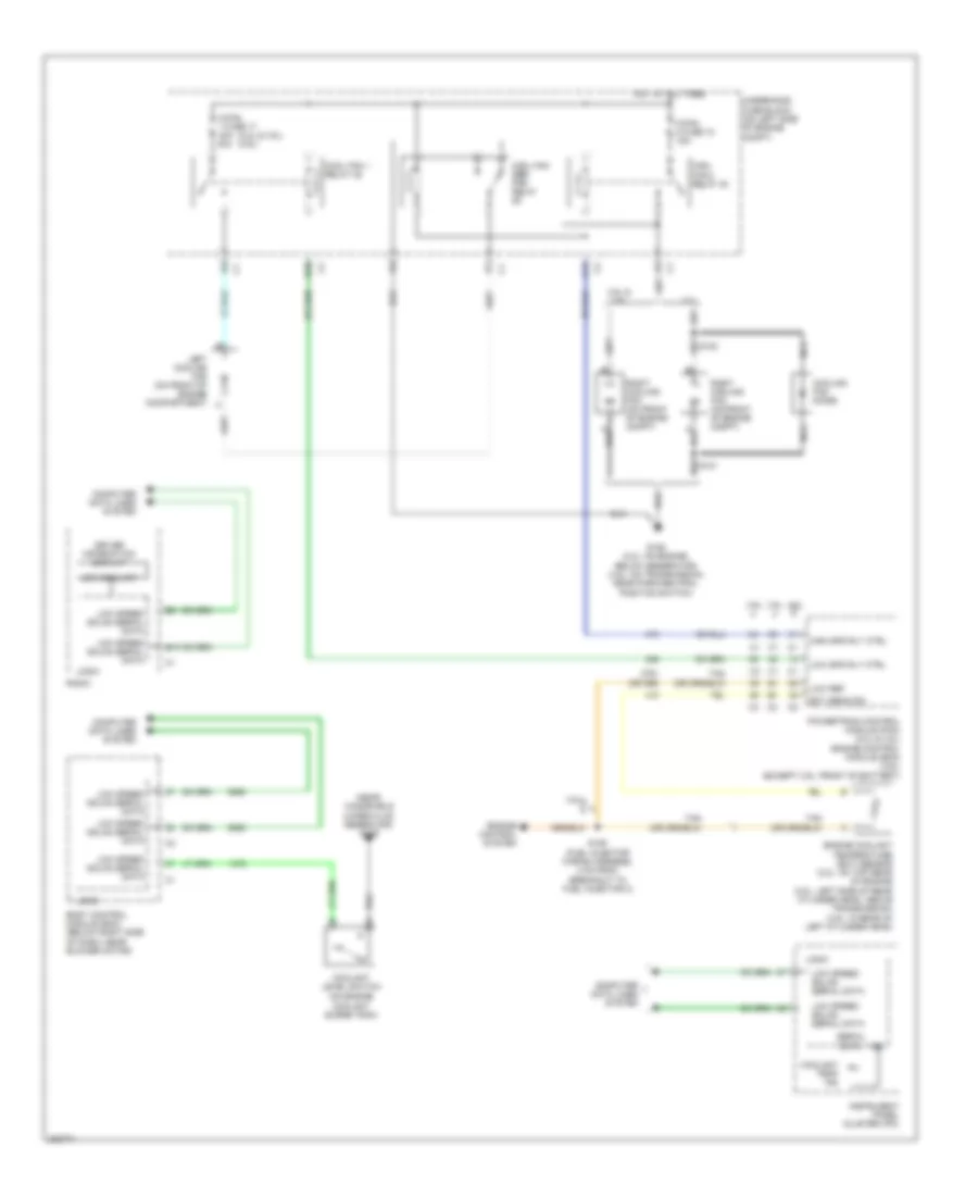
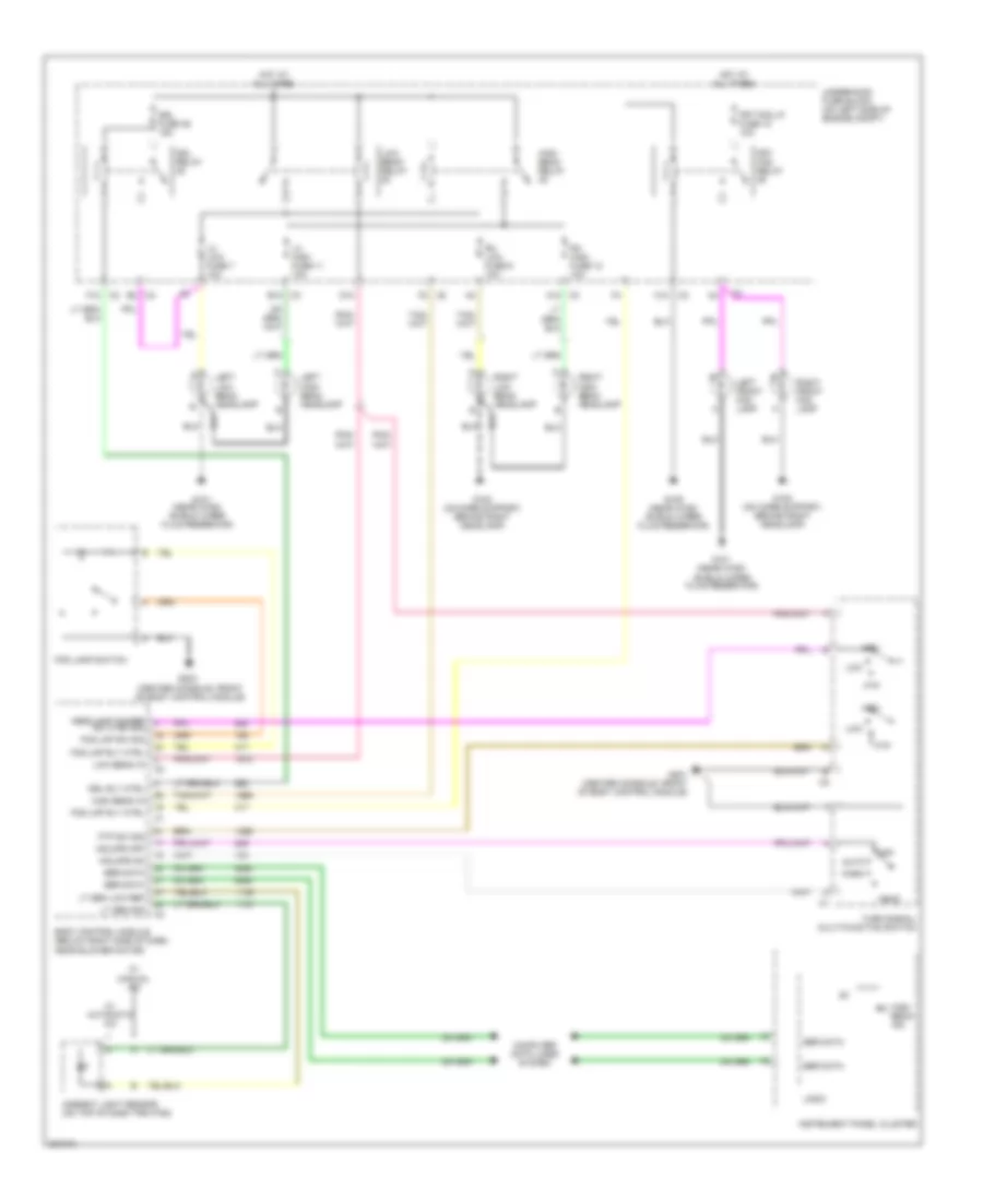
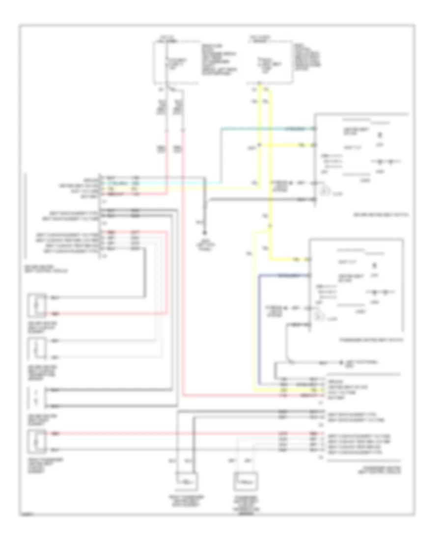
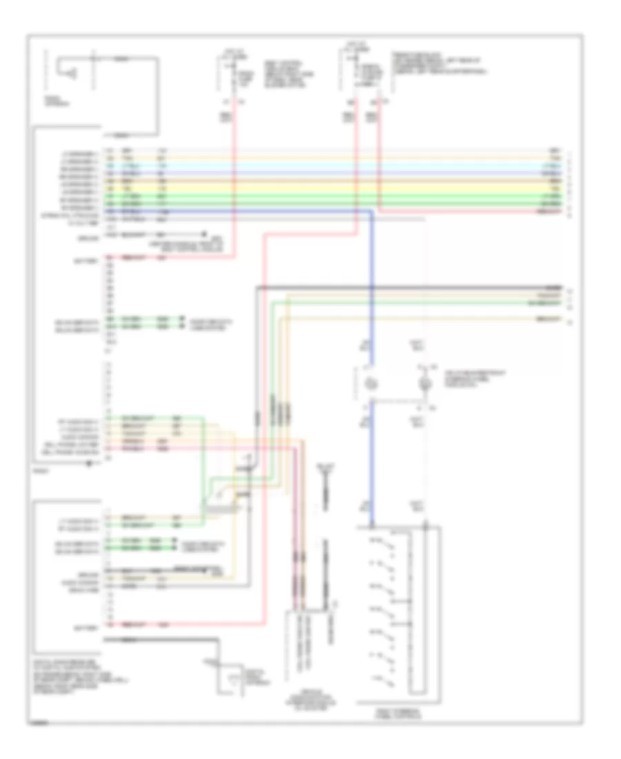
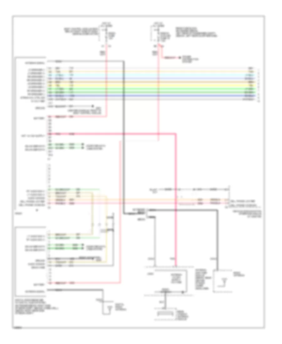
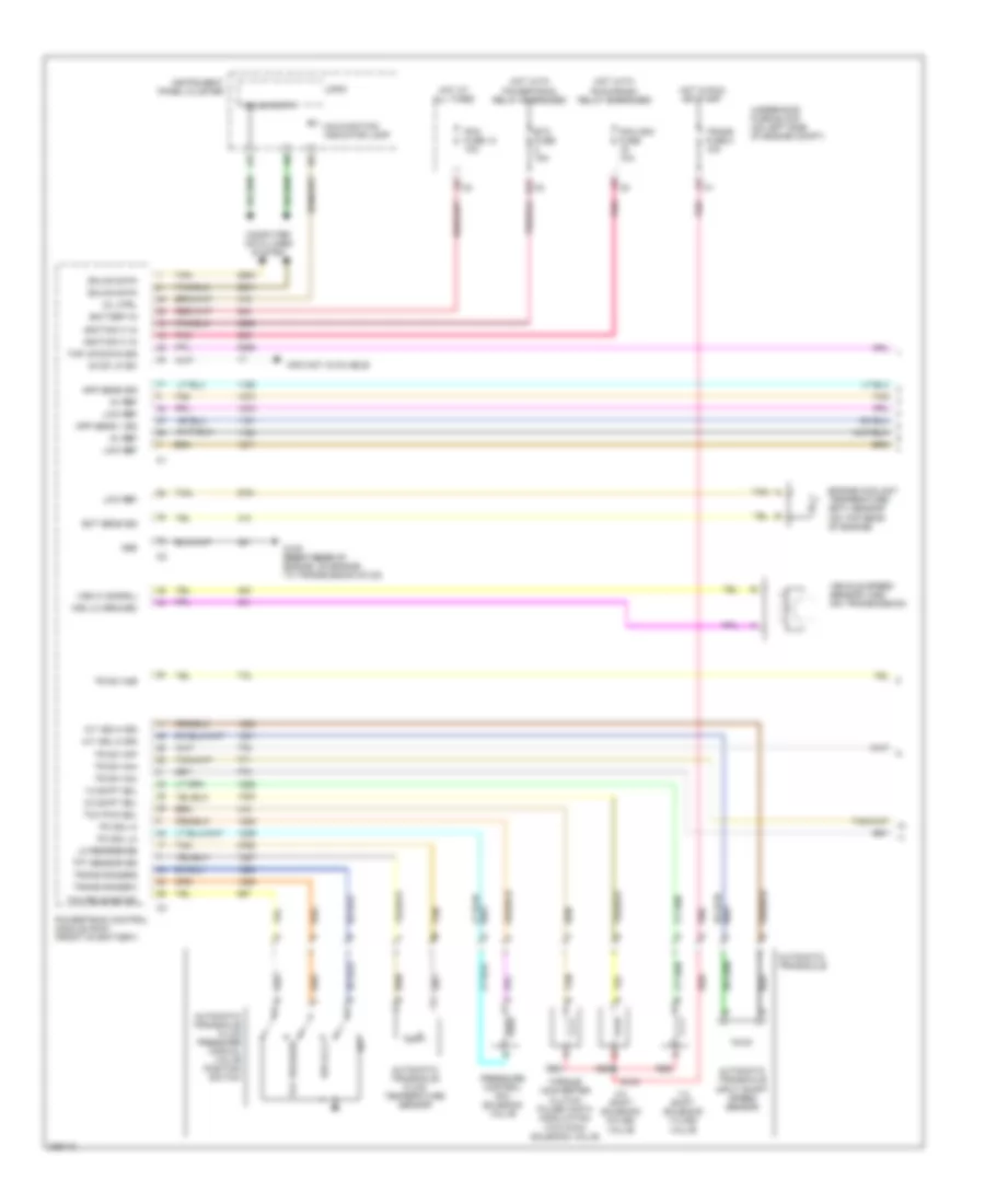
Automatic A/C Wiring Diagram (1 of 2) for Chevrolet Malibu LT 2006
 https://portal-diagnostov.com/license.html
Automotive Electricians Portal FZCO
Automotive Electricians Portal FZCO
https://portal-diagnostov.com/license.html
https://portal-diagnostov.com/license.html
Automotive Electricians Portal FZCO
Automotive Electricians Portal FZCO
List of elements for Automatic A/C Wiring Diagram (1 of 2) for Chevrolet Malibu LT 2006:
- (2.2l & 3.5l) (3.9l)
- (behind grille, on left side of front impact bar) ambient air temperature sensor
- (center console, front of body control module)
- (center console, front of body control module) g203
- 2.2l
- 3.5l & 3.9l
- 40a
- A/c clu fuse 1 10a
- A/c clutch relay
- A/c compressor clutch (lower right front of engine)
- A/c request ind
- A/c request switch
- A10
- A11
- A11 c2
- A12
- A3 c1
- B1 c1
- B10
- B10 c2
- B11
- B12
- B9 c3
- Bat
- Batt
- Blower motor (below right side of dash)
- Blower motor control module (right side of dash, on rear of hvac case)
- Blower motor switch
- Blr mtr spd ctrl
- Blr spd req sig
- C/fan 1 fuse 17 30a
- C/fan 2 fuse 18 30a
- C1 e3
- C2 a5
- C2 c4
- C3 b8
- Computer data lines system
- Cool fan 1 relay
- Cool fan 2 relay
- Cool ser/par relay
- Cooling fan diode
- Dr ctrl a
- Dr ctrl b
- Driver information display
- E1 c2
- E8 c1
- Fresh air ind
- G106 (2.2l: below generator) (3.5l: near park/neutral position switch)
- G106 (2.2l: on engine, below generator) (3.5l: on transmission, near park/neutral position switch)
- G201
- Gnd
- Grd
- Hot at all times
- Hot in run or start
- Hvac control module (center of dash)
- Ign 3
- Inside air temperature sensor
- Interior lights system
- Left cooling fan (on front of engine compartment)
- Lmp sply voltage
- Logic
- Low coolant
- Low ref
- Low spd gmlan
- Low speed gmlan serial data
- Mode switch
- Nca
- Radio
- Recirculation ind
- Recirculation switch
- Right cooling fan (on front of engine compt)
- S101
- S102
- Sply voltage
- Tan
- Temp sens sig
- Temperature control
- Underhood fuse block (on left side of engine compt)
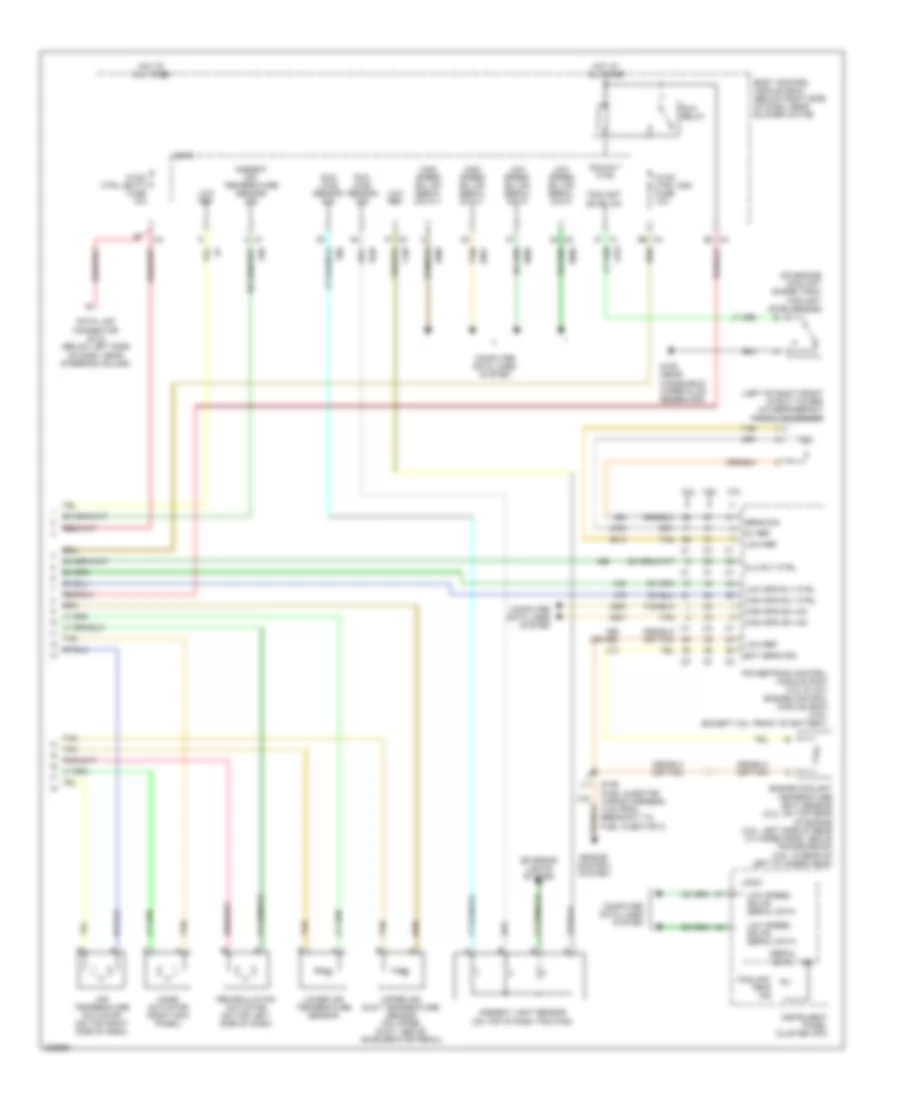
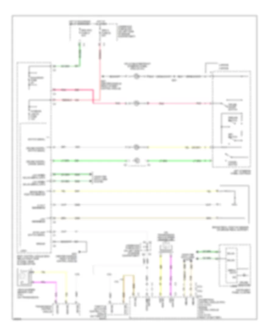
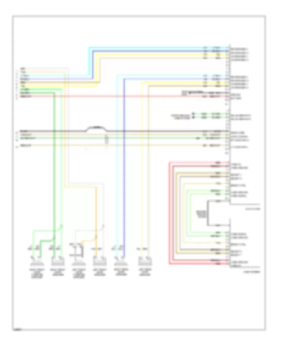
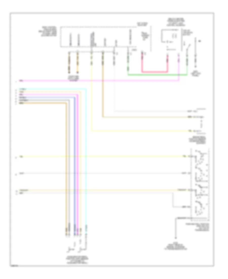
Automatic A/C Wiring Diagram (2 of 2) for Chevrolet Malibu LT 2006
List of elements for Automatic A/C Wiring Diagram (2 of 2) for Chevrolet Malibu LT 2006:
- (left of right front strut tower) a/c refrigerant pressure sensor
- (on engine coolant surge tank) coolant level switch
- (or 469)
- 2.2l
- 3.5l
- 3.9l
- 5v ref
- Air temperature actuator (on top right side of dash)
- Ambient air temperature sensor sig
- Ambient light sensor (on top of dash trim pad)
- Body control module (bcm) (below right side of dash, near blower motor)
- C4 b6
- C4 e2
- Clu rly ctrl
- Computer data lines system
- Coolant level sw
- Coolant temp ind
- Data link connector (dlc) (below left side of dash, near steering column)
- Ect sens sig
- Engine control system
- Engine coolant temperature (ect) sensor (2.2l: on top rear of engine (3.5l: left side of rear cylinder head, above transmission) (3.9l: in rear of left cylinder head)
- Exterior lights system
- G109 (near windshield wiper fluid reservoir)
- High spd gm lan
- High spd rly ctrl
- High speed gm lan serial data +
- High speed gm lan serial data -
- Hot at all times
- Hvac ctrl (batt) fuse 10a
- Hvac ctrl (ign) fuse 10a
- Ign
- Instrument panel cluster (ipc)
- Logic
- Low ref
- Low spd rly ctrl
- Low speed gm lan serial data
- Low speed gmlan serial data
- Lower air temperature sensor
- Mode actuator (right kick panel)
- Powertrain control module (pcm) (2.2l & 3.5l) engine control module (ecm) (3.9l) (except 3.9l: front of battery)
- Recirculation actuator (on top left side of dash)
- Run relay
- Run rly ctrl
- S106 (fuel injector wiring harness, 3 cm from breakout to fuel injector 3)
- Sens sig
- Serial data
- Sun load sensor sig
- Tan
- Upper air duct temperature sensor (on upper duct, above accelerator pedal)
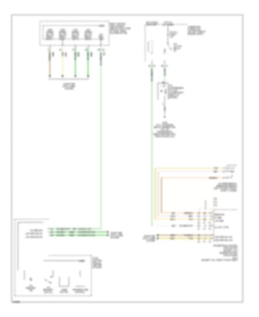
Compressor Wiring Diagram for Chevrolet Malibu LT 2006
List of elements for Compressor Wiring Diagram for Chevrolet Malibu LT 2006:
- (automatic a/c)
- (manual a/c)
- 2.2l
- 3.5l
- 3.9l
- 5v ref
- A/c clu fuse 1 10a
- A/c clutch relay
- A/c compressor clutch (lower right front of engine)
- A/c refrigerant pressure sensor (left of right front strut tower)
- A/c req sig
- A/c request ind
- A/c request switch
- Body control module (bcm) (below right side of dash, near blower motor)
- Clu rly ctrl
- Computer data lines system
- E1 c2
- E8 c1
- G106 (2.2l: on engine, below generator) (3.5l: on transmission, near park/neutral position switch)
- High spd gm lan
- High speed gm lan serial data +
- High speed gm lan serial data -
- Hot at all times
- Hot in run or start
- Hvac control module (center of dash)
- Logic
- Low ref
- Low spd gmlan
- Low speed gm lan serial data
- Mode switch
- Powertrain control module (pcm) (except 3.9l) engine control module (ecm) (3.9l) (except 3.9l: front of battery)
- Sens sig
- Tan
- Temperature control
- Underhood fuse block (on left side of engine compt)
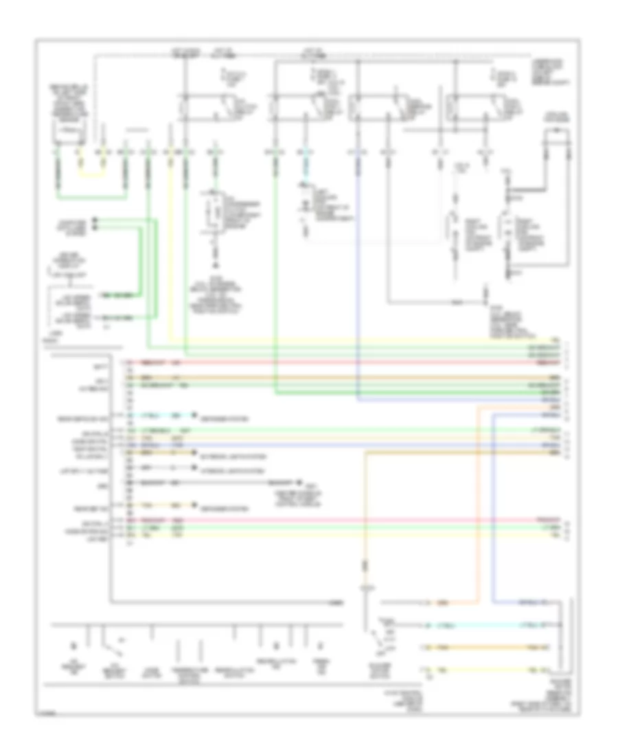
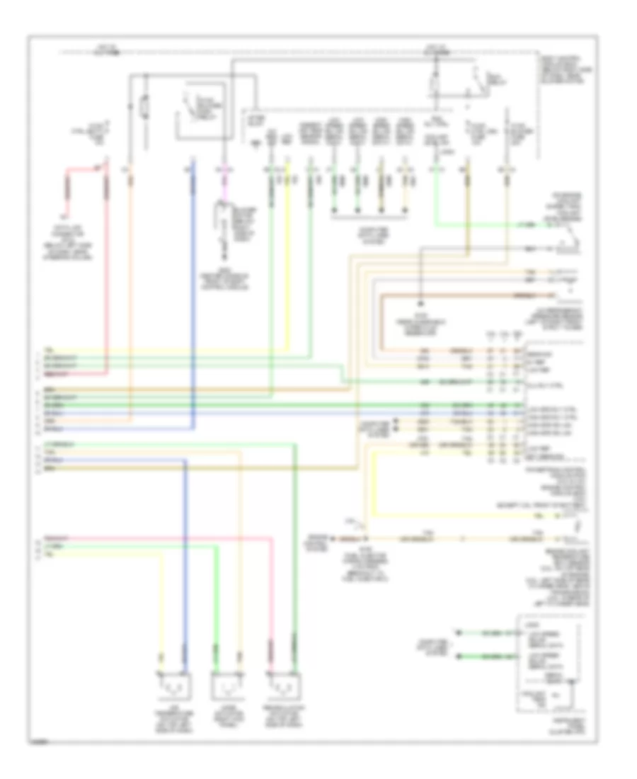
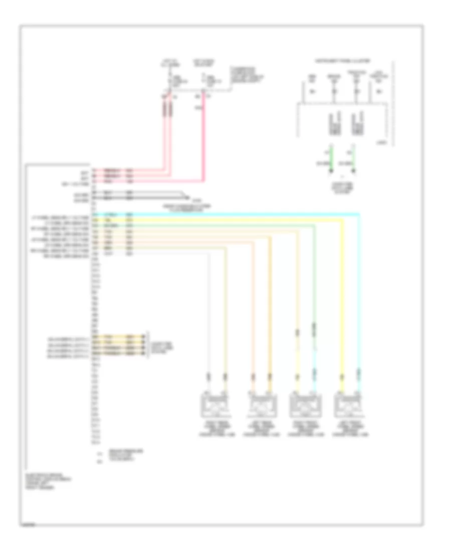
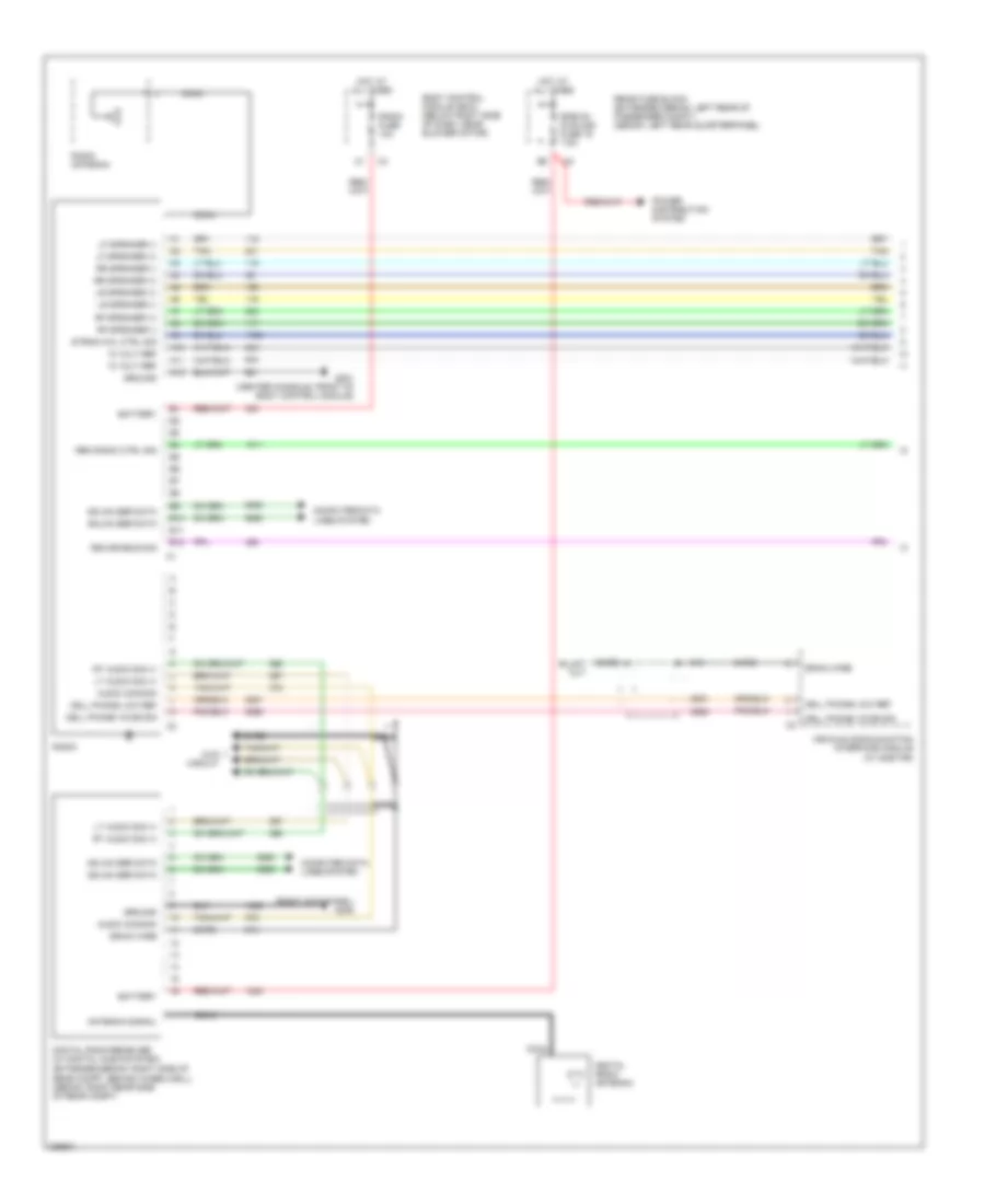
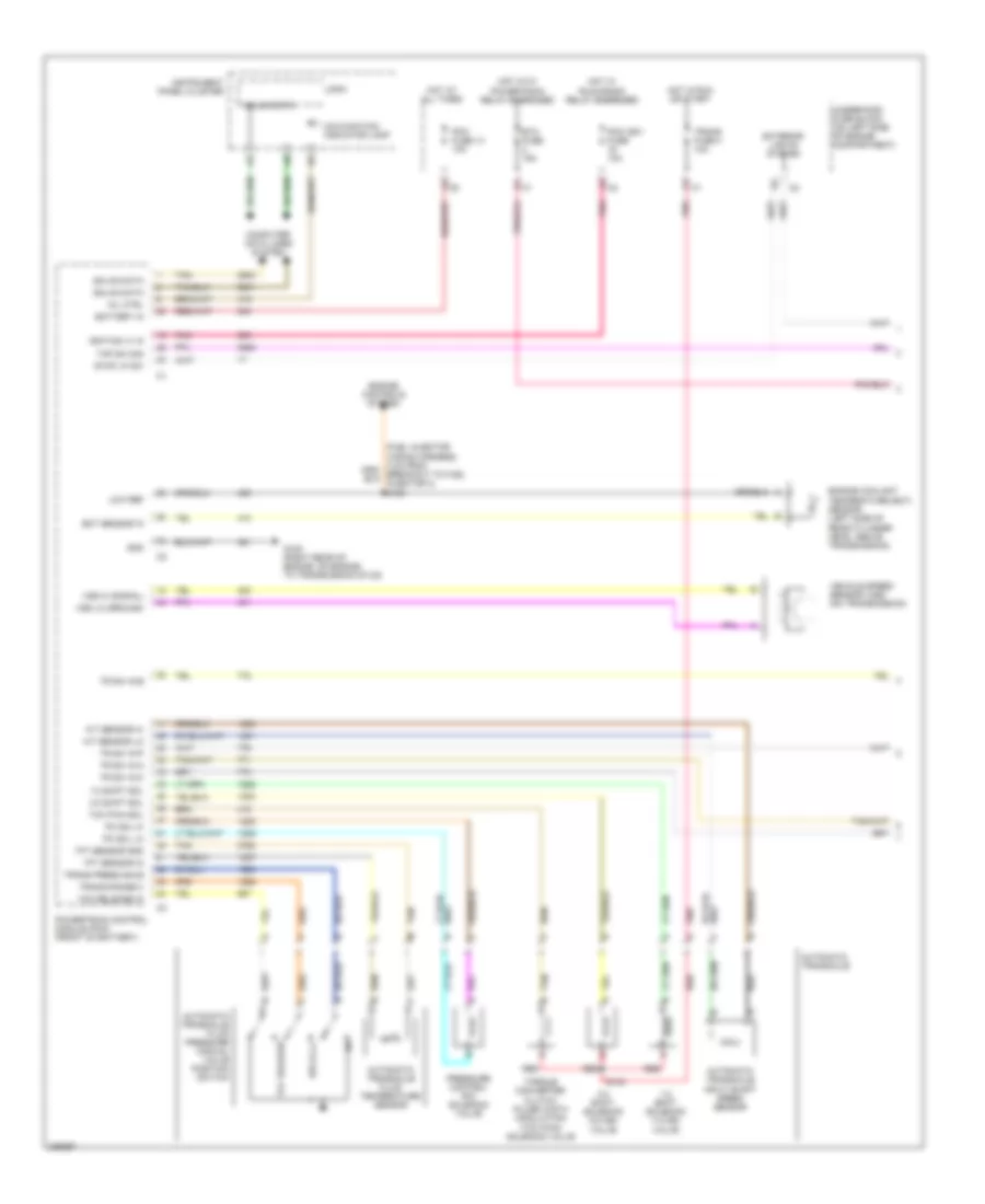
Manual A/C Wiring Diagram (1 of 2) for Chevrolet Malibu LT 2006
List of elements for Manual A/C Wiring Diagram (1 of 2) for Chevrolet Malibu LT 2006:
- (2.2l & 3.5l) (3.9l)
- (behind grille, on left side of front impact bar) ambient air temperature sensor
- (center console, front of body control module)
- 2.2l
- 3.5l & 3.9l
- 40a
- A/c clu fuse 1 10a
- A/c clutch relay
- A/c compressor clutch (lower right front of engine)
- A/c req sig
- A/c request ind
- A/c request switch
- A10
- A11
- A11 c2
- A12
- A3 c1
- A5 c2
- B1 c1
- B10
- B10 c2
- B11
- B12
- B8 c3
- B9 c3
- Batt
- Blower motor resistor assembly (right side of dash, on rear of hvac case)
- Blower motor switch
- C/fan 1 fuse 17 30a
- C/fan 2 fuse 18 30a
- C1 e3
- C2 g
- C4 c2
- Computer data lines system
- Cool fan 1 relay
- Cool fan 2 relay
- Cool ser/par relay
- Cooling fan diode
- Defogger system
- Dr ctrl a
- Dr ctrl b
- Driver information display
- E1 c2
- E8 c1
- Exterior lights system
- Fresh air ind
- G106 (2.2l: below generator) (3.5l: near park/neutral position switch)
- G106 (2.2l: on engine, below generator) (3.5l: on transmission, near park/neutral position switch)
- G201
- Grd
- High
- Hot at all times
- Hot in run or start
- Hvac control module (center of dash)
- Ign 3
- Interior lights system
- Left cooling fan (on front of engine compartment)
- Lmp sply voltage
- Logic
- Low
- Low coolant
- Low ref
- Low speed gmlan serial data
- Mode dr ctrl
- Mode dr pos sig
- Mode switch
- Nca
- Off
- Pk lmp sply
- Radio
- Rear def ind
- Rear defog sw sig
- Recirculation ind
- Recirculation switch
- Right cooling fan (on front of engine compt)
- S101
- S102
- Tan
- Temp dr ctrl
- Temperature control switch
- Underhood fuse block (on left side of engine compt)
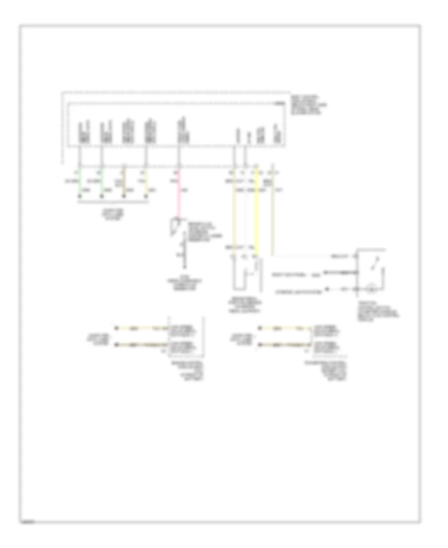
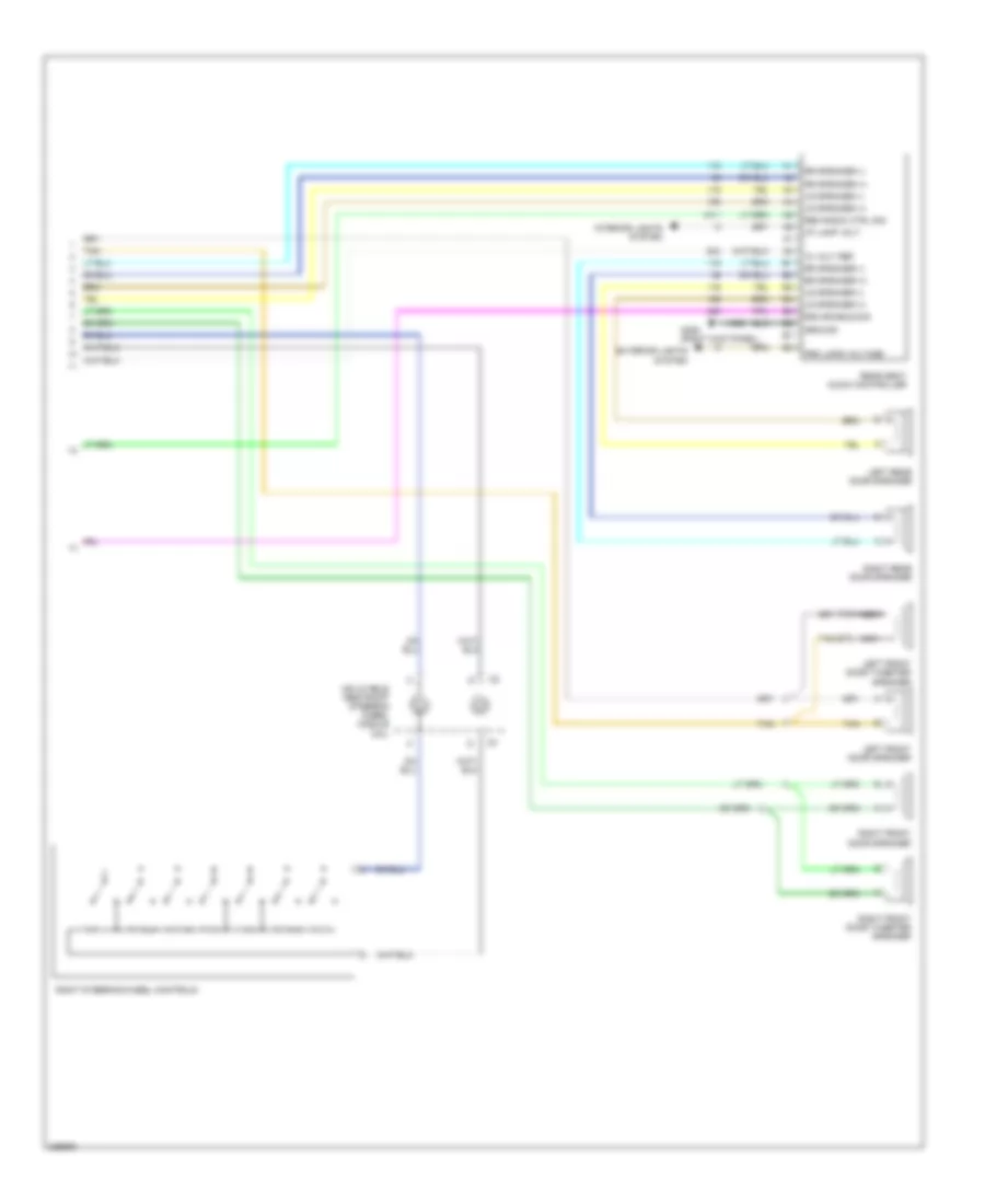
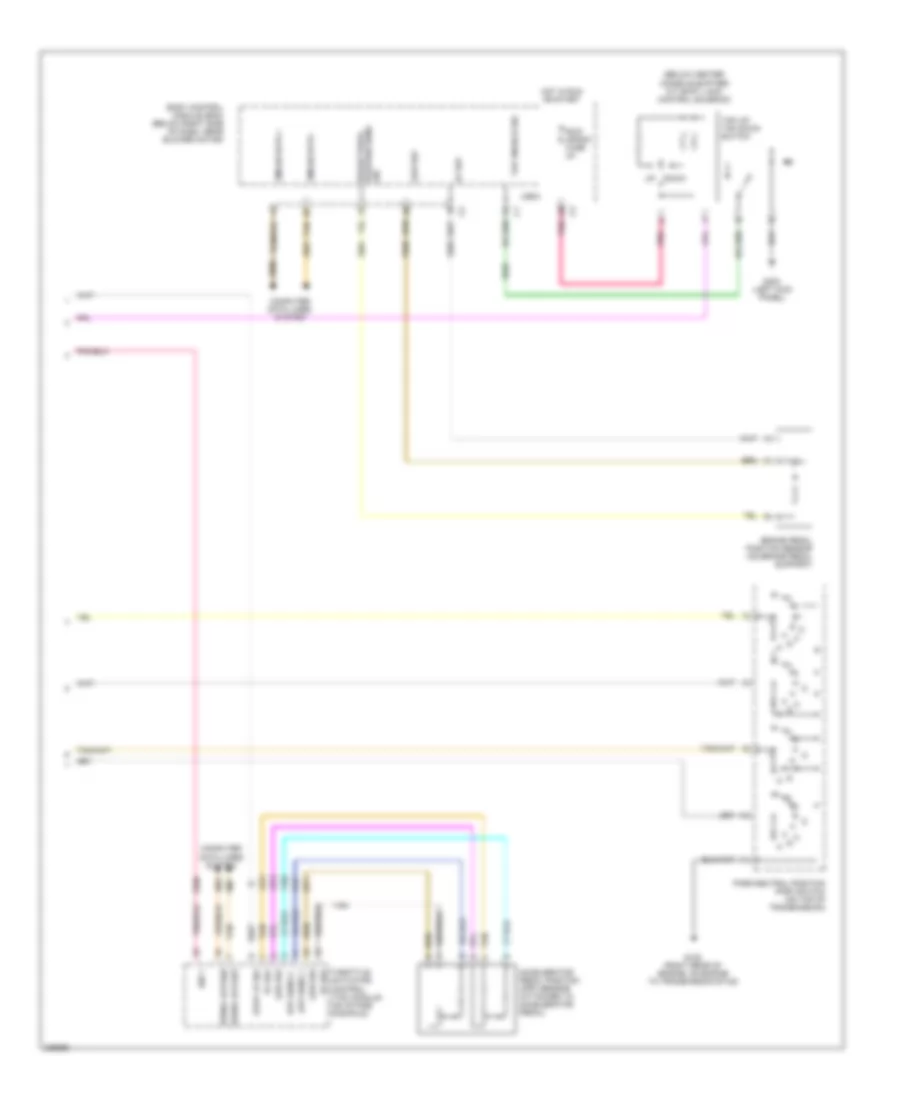
Manual A/C Wiring Diagram (2 of 2) for Chevrolet Malibu LT 2006
List of elements for Manual A/C Wiring Diagram (2 of 2) for Chevrolet Malibu LT 2006:
- (on engine coolant surge tank) coolant level switch
- (or 469)
- 2.2l
- 3.5l
- 3.9l
- 5v ref
- A/c refrigerant pressure sensor (left of right front strut tower)
- A/c req sig
- After blow
- Air temperature actuator (on top left side of dash)
- Ambient air temp sensor signal
- Blower motor (below right side of dash)
- Body control module (bcm) (below right side of dash, near blower motor)
- C4 b3
- Clu rly ctrl
- Computer data lines system
- Coolant level sw
- Coolant temp ind
- D4 c4
- Data link connector (dlc) (below left side of dash, near steering column)
- Ect sens sig
- Engine control system
- Engine coolant temperature (ect) sensor (2.2l: on top rear of engine) (3.5l: left side of rear cylinder head, above transmission) (3.9l: in rear of left cylinder head)
- G109 (near windshield wiper fluid reservoir)
- G203 (center console, front of body control module)
- Grd
- High spd gm lan
- High spd rly ctrl
- High speed gm lan serial data +
- High speed gm lan serial data -
- Hot at all times
- Hvac blower fuse 20a
- Hvac blower high relay
- Hvac ctrl (batt) fuse 10a
- Hvac ctrl (ign) fuse 10a
- Ign
- Instrument panel cluster (ipc)
- Logic
- Low ref
- Low spd rly ctrl
- Low speed gm lan serial data
- Low speed gmlan serial data
- Mode actuator (right kick panel)
- Powertrain control module (pcm) (2.2l & 3.5l) engine control module (ecm) (3.9l) (except 3.9l: front of battery)
- Recirculation actuator (on top left side of dash)
- Run relay
- Run rly ctrl
- S106 (fuel injector wiring harness, 3 cm from breakout to fuel injector 3)
- Sens sig
- Serial data
- Tan
ANTI-LOCK BRAKES
Anti-lock Brakes Wiring Diagram (1 of 2) for Chevrolet Malibu LT 2006
List of elements for Anti-lock Brakes Wiring Diagram (1 of 2) for Chevrolet Malibu LT 2006:
- (near windshield wiper fluid reservoir)
- A10
- A11
- A12
- A13
- A14
- Abs fuse 15 10a
- Abs fuse 24 60a
- Abs ind
- B10
- B11
- B12
- B13
- B14
- Bat
- Brake ind
- Brake pressure modulator valve (bpmv)
- C10
- C11
- C12
- C13
- C14
- Computer data lines system
- Electronic brake control module (ebcm) (inside left front fender)
- G109
- Gmlan serial data (+)
- Gmlan serial data (-)
- Hot at all times
- Hot in run or start
- Ign 1 voltage
- Instrument panel cluster
- Left front wheel speed sensor (inside wheel hub)
- Left rear wheel speed sensor (inside wheel hub)
- Lf wheel sens sply voltage
- Lf wheel spd sens sig
- Logic
- Low speed
- Low speed gmlan serial data
- Low traction ind
- Lr wheel sens sply voltage
- Lr wheel spd sens sig
- Pnk
- Rf wheel sens sply voltage
- Rf wheel spd sens sig
- Right front wheel speed sensor (inside wheel hub)
- Right rear wheel speed sensor (inside wheel hub)
- Rr wheel sens sply voltage
- Rr wheel spd sens sig
- Serial data gmlan
- Sig grd
- Tan
- Traction off ind
- Underhood fuse block (on left side of engine compt)
Anti-lock Brakes Wiring Diagram (2 of 2) for Chevrolet Malibu LT 2006
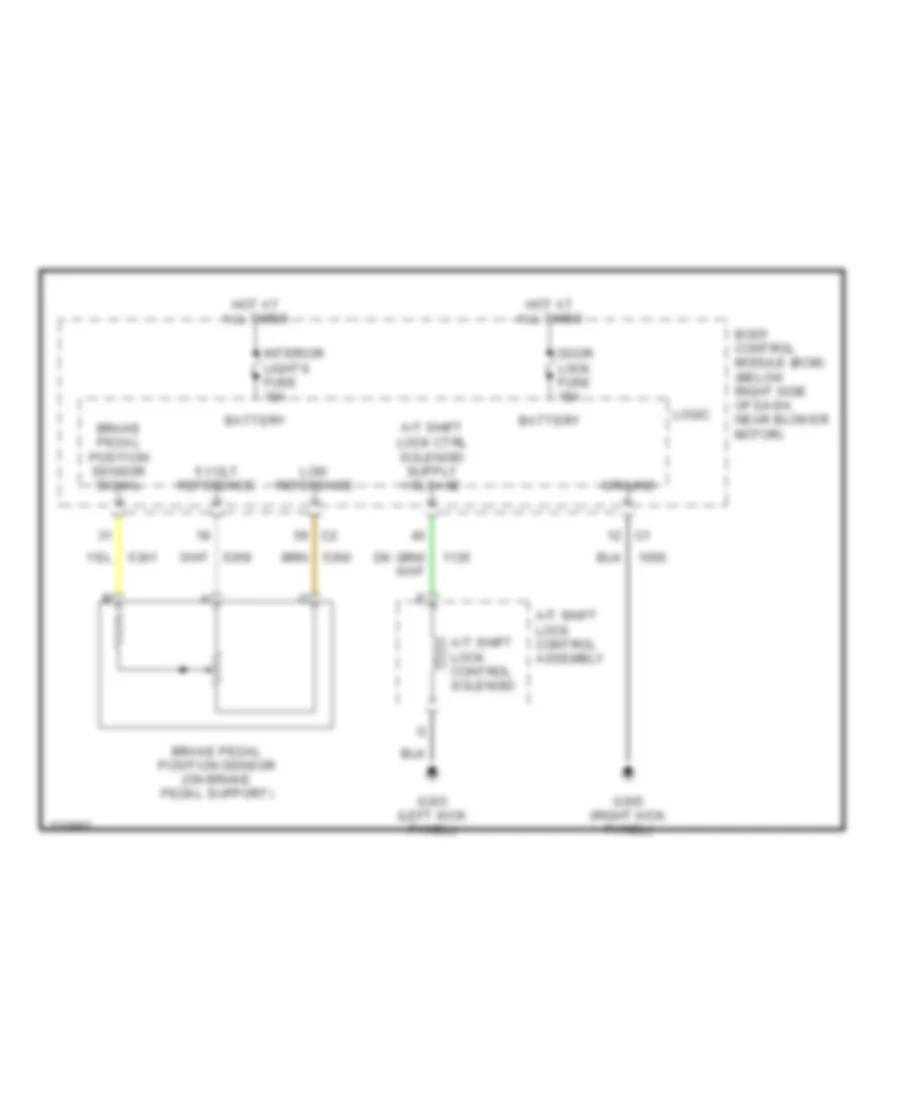
List of elements for Anti-lock Brakes Wiring Diagram (2 of 2) for Chevrolet Malibu LT 2006:
- (right kick panel)
- 5v ref
- Body control module (bcm) (below right side of dash, near blower motor)
- Brake fluid level sensor
- Brake fluid level switch (on brake master cylinder reservoir)
- Brake pedal position sensor (on brake pedal support)
- Brk pos sens sig
- Computer data lines system
- Data bus (-) gmlan serial high speed
- Engine control module (ecm) (3.9l) (in front of battery)
- G109 (near windshield wiper fluid reservoir)
- G305
- Gmlan serial data
- Gmlan serial data bus (+)
- High speed
- High speed gmlan serial data bus (+)
- High speed gmlan serial data bus (-)
- Interior lights system
- Logic
- Low ref
- Low speed
- Pnk
- Powertrain control module (pcm) (except 3.9l) (in front of battery)
- Serial data gmlan low speed
- Signal
- Tan
- Trac ctrl sw sig
- Traction control switch (in center console below hvac control module)
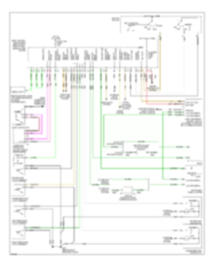
ANTI-THEFT
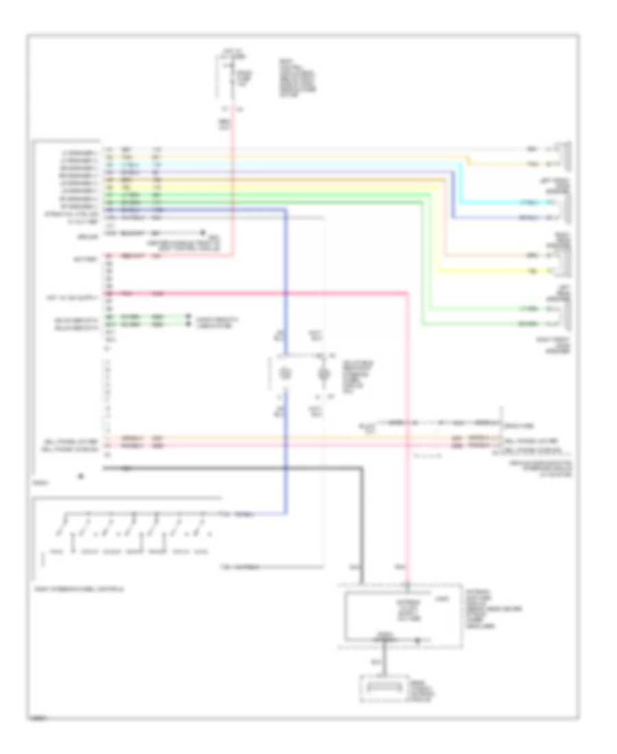
Anti-theft Wiring Diagram for Chevrolet Malibu LT 2006
List of elements for Anti-theft Wiring Diagram for Chevrolet Malibu LT 2006:
- (center console, front of body control module)
- (center of dash) hvac control module
- (near windshield wiper fluid reservoir) g101
- 5 volt ref
- Acc
- Acc volt
- Acc volt sig
- Ajar
- Ajar switch signal
- B10
- Battery
- Body control module (bcm) (below right side of dash, near blower motor)
- C4 c3
- Closed
- Cluster/ theft fuse 10a
- Cntrl
- Computer data lines system
- Door lock
- Door lock fuse 15a
- Driver door latch assembly
- Driver door lock switch
- Exterior lights system
- G201
- G301 (behind right rear seat back)
- Ground
- Headlights system
- Headlp high beam rel
- High spd gmlan serial data
- Hood ajar switch
- Horn relay control
- Horns system
- Hot at all times
- Ignition switch
- Instrument panel cluster
- Interior lights system
- Key in ignition switch
- Left rear door latch assembly
- Lock
- Logic
- Low spd gmlan
- Low spd serial
- Off
- Off/run/ crank sig
- Park lp relay cntrl
- Passenger door latch assembly
- Passenger door lock switch
- Power distribution system
- Radio
- Remote control door lock receiver (rcdlr) (on rear package shelf)
- Right rear door latch assembly
- Run
- Security ind
- Serial data
- Signal key switch driver dr
- Signal lck/unlck
- Start
- Sw sig hood ajar
- Sw sig lid ajar rr compt
- Tan
- Theft deterrent control module (attached to ignition key cylinder housing)
- Trunk, tailgate, fuel doors system
- Underhood fuse block (on left side of engine compt)
- Unlock
- Vehicle communications interface module
- W/ auto air conditioning
- W/ vehicle communi- cations
- W/o auto air conditioning
- W/o vehicle communi- cations
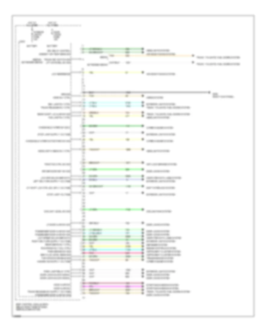
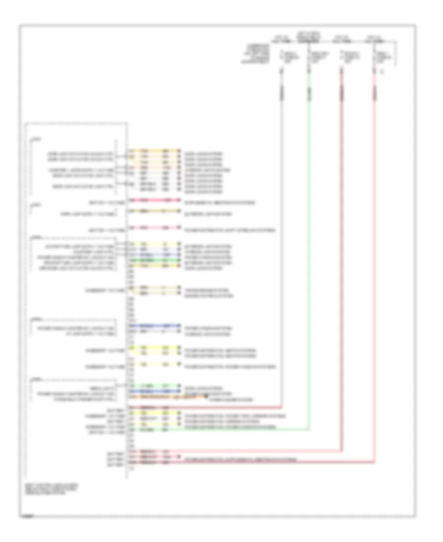
BODY CONTROL MODULES
Body Control Modules Wiring Diagram (1 of 4) for Chevrolet Malibu LT 2006
List of elements for Body Control Modules Wiring Diagram (1 of 4) for Chevrolet Malibu LT 2006:
- (extended sedan)
- (sedan)
- A/t shift lck ctrl sol sply voltage
- Air conditioning system
- Ambient air temp sens sig
- Anti-lock brakes system
- Battery
- Body control module (bcm) (below right side of dash, near blower motor)
- Brk fluid level sens sig
- Computer data lines system
- Coolant level sw sig
- Cooling fans system
- Defogger system
- Door lock/unlock signal
- Door locks fuse 15a
- Door locks system
- Driver door key sw sig
- Drl relay control
- Engine controls system
- Extended sedan
- Exterior lights system
- Fog lamp rly ctrl
- G305 (right kick panel)
- Ground
- Headlamp hi beam rly ctrl
- Headlights system
- Hood ajar sw
- Horn rly ctrl
- Horns system
- Hot at all times
- Instrument cluster system
- Interior lights fuse 10a
- Lf door ajar sw sig
- Lift gate rel sw sig
- Logic
- Low reference
- Low spd gmlan ser data
- Low speed gmlan ser data
- Park brake sw sig
- Park lamp relay ctrl
- Passenger door ajar sw sig
- Pnk
- Rear compt lid ajar sw sig
- Rear defog rly ctrl
- Rev lamp rly ctrl
- Run/crank rly coil ctrl
- Sedan
- Shift interlock system
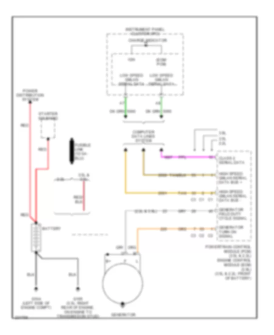
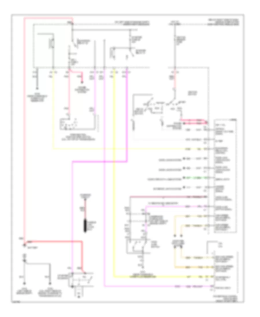
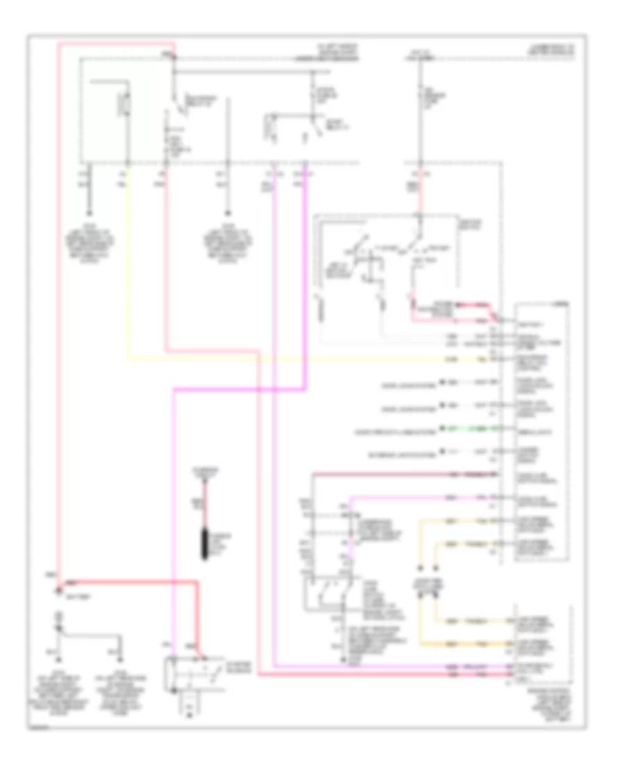
- Starting/charging system
- Stop lamp voltage
- Tan
- Tap/up/down enable sig
- Traction ctrl sw sig
- Transmissions system
- Trunk key switch sig
- Trunk release rly ctrl
- Trunk, tailgate, fuel doors system
- Trunk. tailgate, fuel doors system
- Windshield wiper motor park sw sig
- Windshield wiper sw sig 2
- Wiper/washer system
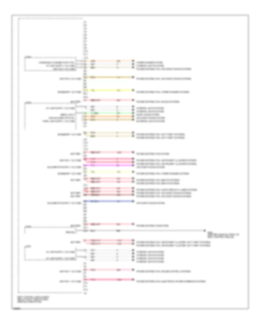
Body Control Modules Wiring Diagram (2 of 4) for Chevrolet Malibu LT 2006
List of elements for Body Control Modules Wiring Diagram (2 of 4) for Chevrolet Malibu LT 2006:
- A10
- A11
- A12
- Accessory voltage
- B10
- B11
- B12
- Battery
- Body control module (bcm) (below right side of dash, near blower motor)
- C11
- C12
- Courtesy lamp ctrl
- D10
- D11
- D12
- Door lock actuator lock ctrl
- Door lock actuator unlock ctrl
- Door locks system
- Drr door lock actuator unlock ctrl
- Engine controls system
- Exterior lights system
- Hot at all times
- Hot w/ run/ crank relay energized
- Ibcm (r/c) fuse 21 30a
- Ibcm 1 fuse 20 30a
- Ibcm 2 fuse 25 50a
- Ignition 1 voltage
- Interior lights system
- Logic
- Pnk
- Power distribution, mirrors systems
- Power distribution, power tops, mirrors systems
- Power distribution, power windows systems
- Power distribution, seats systems
- Power distribution, shift interlock systems
- Power window master sw lockout sig
- Power windows system
- Power windows system (or 477)
- Run rly fuse 19 30a
- Serial data
- Tan
- Transmissions system
- Underhood fuse block (on left side of engine compartment)
- Windshield washer pump ctrl
- Wiper/washer system
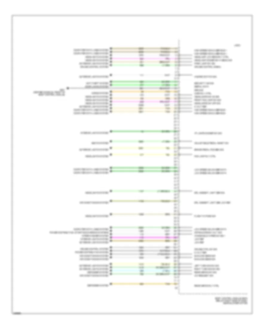
Body Control Modules Wiring Diagram (3 of 4) for Chevrolet Malibu LT 2006
List of elements for Body Control Modules Wiring Diagram (3 of 4) for Chevrolet Malibu LT 2006:
- A10
- A11
- A12
- Accessory voltage
- Air conditioning system
- B10
- B11
- B12
- Battery
- Body control module (bcm) (below right side of dash, near blower motor)
- C10
- C11
- C12
- D10
- D11
- D12
- Door locks system
- E10
- E11
- E12
- Exterior lights system
- F10
- F11
- F12
- G203 (center console, front of body control module)
- Ground
- High blower mtr ctrl
- Ignition 1 voltage
- Ignition 3 voltage
- Interior lights system
- Logic
- Pnk
- Power distribution system
- Power distribution, air conditioning systems
- Power distribution, anti-theft systems
- Power distribution, computer data lines systems
- Power distribution, cruise control systems
- Power distribution, electronic power steering systems
- Power distribution, instrument cluster systems
- Power distribution, instrument cluster, anti-theft systems
- Power distribution, seats systems
- Power distribution, sound systems
- Power distribution, wiper/washer systems
- Power distributionsystem
- Serial data
- Windshield washer pump ctrl
- Wiper/washer system
Body Control Modules Wiring Diagram (4 of 4) for Chevrolet Malibu LT 2006
List of elements for Body Control Modules Wiring Diagram (4 of 4) for Chevrolet Malibu LT 2006:
- 5 volt ref
- A/c request sig
- Adjustable pedal inhibit sw
- Air conditioning system
- Anti-theft system
- Body control module (bcm) (below right side of dash, near blower motor)
- Brake pedal pos sen sig
- Computer data lines system
- Cruise control signal
- Cruise control system
- Cruise ctrl sw sig
- Defogger system
- Door locks system
- Drl ambient light sen low ref
- Drl ambient light sen sig
- Exterior lights system
- Flash to pass sig
- Fog lamp rly ctrl
- Front fog lamp sw sig
- G201 (center console, front of body control module)
- Ground
- Hazard switch sig
- Headlamp dimmer sw hi beam sig
- Headlamp low beam rly ctrl
- Headlamps sw off sig
- Headlamps sw on sig
- Headlights system
- High speed gmaln ser bus +
- High speed gmaln ser bus -
- Horn rly ctrl
- Horns system
- I/p lamps dimmer sw sig
- Interior lights system
- Left turn sig sw sig
- Logic
- Low ref
- Low speed gmlan ser data
- Off/run/crank volt sig
- Park lamp sw isg
- Power distribution system
- Power distribution, starting/charging systems
- Rear defog rly ctrl
- Rear defog sw sig
- Right turn sig sw sig
- Seats system
- Security ind sig
- Serial data
- Sunload sens sig
- Tan
- Windshield wiper sw sig 1
- Wiper/washer system
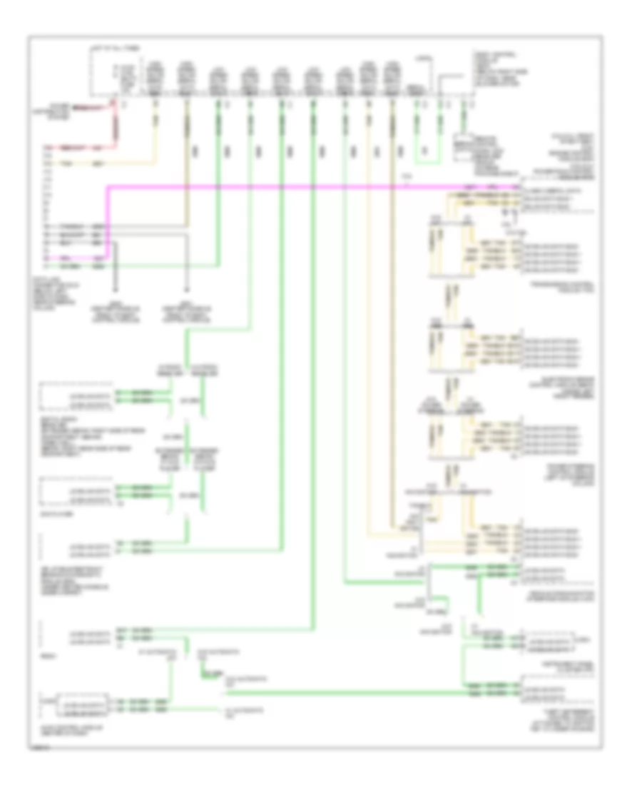
COMPUTER DATA LINES
Computer Data Lines Wiring Diagram for Chevrolet Malibu LT 2006
List of elements for Computer Data Lines Wiring Diagram for Chevrolet Malibu LT 2006:
- (3.5l/2.2l) powertrain control module (pcm)
- (3.5l/2.2l: front of battery) (3.9l) engine control module (ecm)
- 2.2l
- 2.2l/3.5l
- 3.9l
- B10
- B11
- B12
- Body control module (bcm) (below right side of dash, near blower motor)
- Class 2 serial data
- Data link connector (dlc) (below left side of dash, near steering column)
- Digital radio receiver (extended sedan: right side of rear compartment, behind wheelwell) (sedan: right rear side of rear compartment)
- Dvd player
- Electronic brake control module (ebcm) (inside left front fender)
- Extended sedan/ w/ dvd player
- Extended sedan/ w/o dvd player
- G201 (center console, front of body control module)
- G203 (center console, front of body control module)
- Gmlan data bus +
- Gmlan data bus -
- High speed gmlan serial data bus +
- High speed gmlan serial data bus -
- Hot at all times
- Hs gmlan data bus +
- Hs gmlan data bus -
- Hvac control module (center of dash)
- Hvac ctrl (batt) fuse 10a
- Inflatable restraint sensing & diagnostic module (sdm) (under center console, under carpet)
- Instrument panel cluster (ipc)
- Logic
- Low speed gmlan serial data
- Ls gmlan data
- Power distribution system
- Power steering control module (left of steering column)
- Radio
- Remote control door lock receiver (rcdlr) (on rear package shelf)
- Serial data
- Tan
- Theft deterrent control module (attached to ignition key cylinder housing)
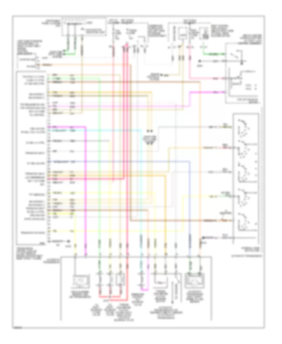
- Transmission control module (tcm)
- Vehicle communication interface module (vcim)
- W/ a/t
- W/ abs
- W/ automatic a/c
- W/ navigation
- W/ power steering
- W/ radio receiver
- W/o a/t
- W/o abs
- W/o automatic a/c
- W/o navi- gation
- W/o navigation
- W/o power steering
- W/o radio receiver
COOLING FAN
Cooling Fan Wiring Diagram for Chevrolet Malibu LT 2006
List of elements for Cooling Fan Wiring Diagram for Chevrolet Malibu LT 2006:
- (2.2l & 3.5l) (3.9l)
- (near windshield wiper fluid reservoir) g109
- (on engine coolant surge tank)
- (or 469)
- 2.2l
- 3.5l
- 3.5l & 3.9l
- 3.9l
- A11
- B10
- Body control module (bcm) (below right side of dash, near blower motor)
- C/fan 1 fuse 17 30a 40a
- C/fan 2 fuse 18 15a
- Computer data lines system
- Cool fan 1 relay 28
- Cool fan 2 relay 30
- Cool fan ser/ par relay
- Coolant level switch
- Coolant temp ind
- Cooling fan diode
- Driver information display
- Ect sens sig
- Engine control system
- Engine coolant temperature (ect) sensor (2.2l: on top rear of engine (3.5l: left side of rear cylinder head, above transmission) (3.9l: in rear of left cylinder head)
- G106 (2.2l: on engine, below generator) (3.5l: on transmission, near park/neutral position switch)
- High spd rly ctrl
- Hot at all times
- Ign
- Instrument panel cluster (ipc)
- Left cooling fan (on front of engine compartment)
- Logic
- Low coolant
- Low ref
- Low spd rly ctrl
- Low speed gmlan serial data
- Nca
- Powertrain control module (pcm) (2.2l & 3.5l) engine control module (ecm) (3.9l) (except 3.9l: front of battery)
- Radio
- Right cooling fan (on front of engine compt)
- S101
- S102
- S106 (fuel injector wiring harness, 3 cm from breakout to fuel injector 3)
- Serial data
- Underhood fuse block (on left side of engine compt)
CRUISE CONTROL
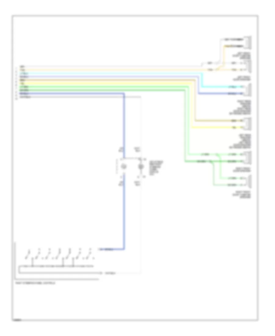
Cruise Control Wiring Diagram for Chevrolet Malibu LT 2006
List of elements for Cruise Control Wiring Diagram for Chevrolet Malibu LT 2006:
- (3.5l) c1
- (3.9l) c3
- (on transmission) vehicle speed sensor (vss)
- 3 spoke
- 3.5l
- 3.9l
- 4 spoke
- 5 volt reference
- Body control module (bcm) (below right side of dash, near blower motor)
- Brake pedal position sens sig
- Brake pedal position sensor (on brake pedal support)
- C1 (2.2l)
- C2 d3
- Cancel switch
- Computer data lines system
- Cruise control cancel signal
- Cruise control switch signal
- Cruise indicator
- Cruise on/off switch
- G201 (center console, front of body control module)
- Gmlan
- Ground
- High sig
- High sig vss
- Hot at all times
- Hot w/ run/crank relay energized
- Ibcm (r/c) fuse 21 30a
- Ibcm 2 fuse 25 50a
- Ign
- Inflatable restraint steering wheel module coil
- Instrument panel cluster
- Interior lights fuse 10a
- Left steering wheel controls
- Logic
- Low reference
- Low sig
- Low sig vss
- Low speed gmlan serial data
- Pnk
- Powertrain control module (pcm) (2.2l & 3.5l) engine control module (3.9l) (2.2l & 3.5l: front of battery)
- Resume switch
- Run/crank fuse 2a
- S201
- Serial data
- Set switch
- Stop lamp switch signal
- Stp sig
- Sw sig
- Sw sig stop lamp
- Switch signal
- Tan
- Throttle actuator control (tac) module (on throttle body)
- Transmission control module
- Underhood fuse block (on left side of engine compartment)
- Vehicle speed sensor (vss) (3.9l) (on transmission)
DEFOGGERS
Defoggers Wiring Diagram for Chevrolet Malibu LT 2006
List of elements for Defoggers Wiring Diagram for Chevrolet Malibu LT 2006:
- B12
- Body control module (bcm) (below right side of dash, near blower motor)
- C12
- Computer data lines system
- Defog ind
- Defog switch
- Driver outside rearview mirror
- G201 (center console, front of body control module)
- G301 (sedan) (behind right rear seat back)
- G302 (extended sedan) (behind rear seat, on left quarterpanel)
- G302 (extended sedan: behind rear seat, on left quarterpanel) (sedan: behind left rear seat)
- G303 (left kick panel)
- Hot at all times
- Htd mir fuse 24 10a
- Hvac control module (automatic a/c) (center of dash)
- Hvac control module (manual a/c) (center of dash)
- Logic
- Low spd gmlan ser data
- Low speed gmlan ser data
- Nca
- Passenger outside rearview mirror
- R/wdo defog relay
- Rear fuse block (extended sedan: left rear of passenger compt) (sedan: left rear quarterpanel)
- Rear window defogger grid
- Rr defog fuse 23 30a
- Rr defog rly ctrl
- Rr defog sw sig
- Tan
ELECTRONIC POWER STEERING
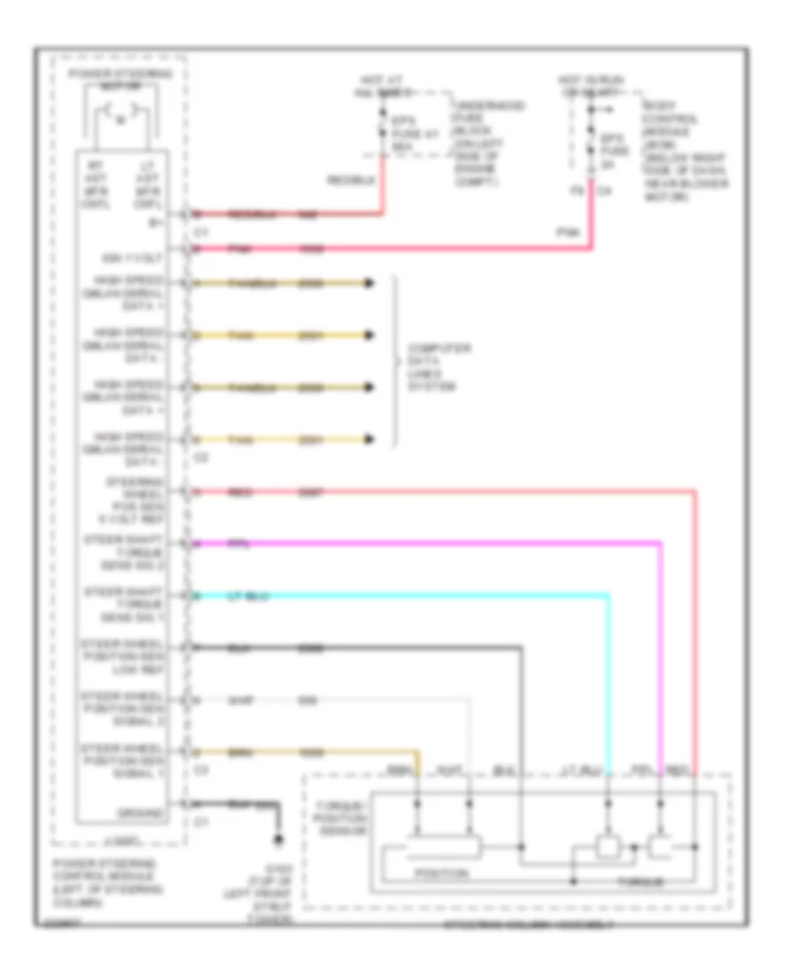
Electronic Power Steering Wiring Diagram for Chevrolet Malibu LT 2006
List of elements for Electronic Power Steering Wiring Diagram for Chevrolet Malibu LT 2006:
- Body control module (bcm) (below right side of dash, near blower motor)
- Computer data lines system
- Eps fuse 2a
- Eps fuse 41 80a
- F9 c4
- G103 (top of left front strut tower)
- Ground
- High speed gmlan serial data +
- High speed gmlan serial data -
- Hot at all times
- Hot in run or start
- Ign 1 volt
- Logic
- Lt ast mtr cntl
- Pnk
- Position
- Power steering control module (left of steering column)
- Power steering motor
- Red
- Rt ast mtr cntl
- Steer shaft torque sens sig 1
- Steer shaft torque sens sig 2
- Steer wheel position sen low ref
- Steer wheel position sen signal 1
- Steer wheel position sen signal 2
- Steering column assembly
- Steering wheel pos sen 5 volt ref
- Tan
- Torque
- Torque/ position sensor
- Underhood fuse block (on left side of engine compt)
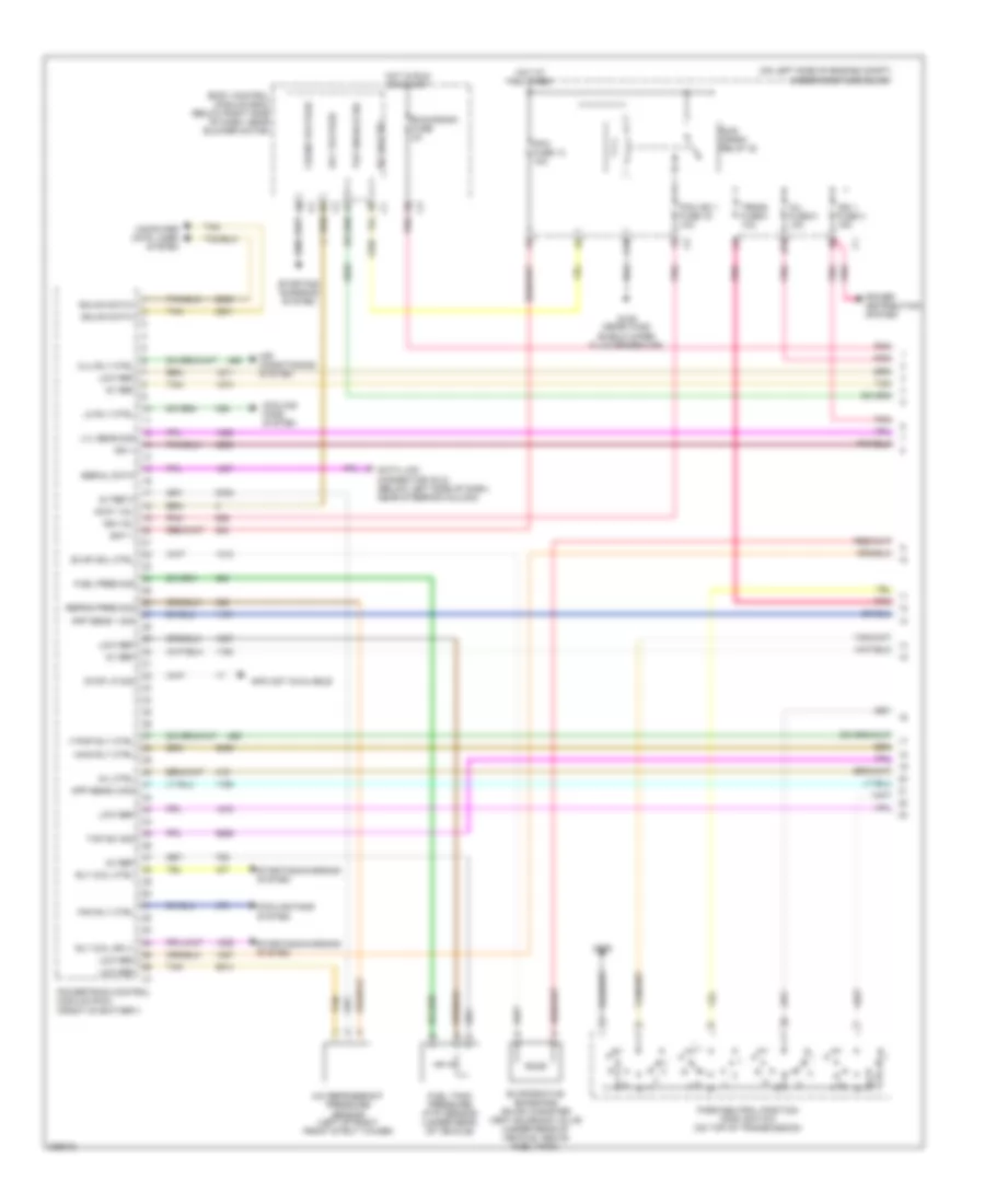
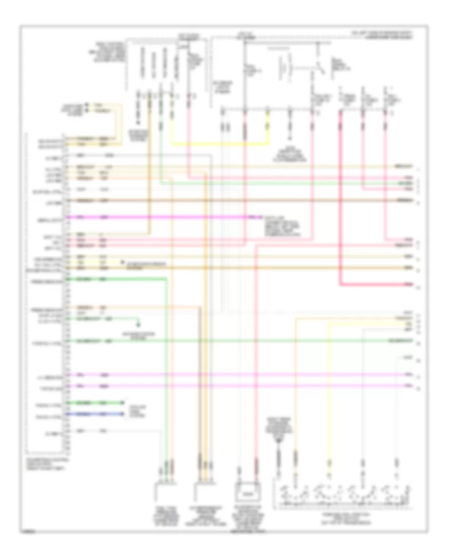
ENGINE PERFORMANCE
2.2L VIN F
2.2L VIN F, Engine Performance Wiring Diagram (1 of 4) for Chevrolet Malibu LT 2006
List of elements for 2.2L VIN F, Engine Performance Wiring Diagram (1 of 4) for Chevrolet Malibu LT 2006:
- (on left side of engine compt) underhood fuse block
- 5v ref
- 5v ref 2
- A/c refrigerant pressure sensor (left of right front strut tower)
- Acc voltage
- Accy vol
- Air conditioning system
- App sens 1 sig
- App sens 2 sig
- B10
- Bat +
- Body control module (bcm) (below right side of dash, near blower motor)
- C10
- Clu rly ctrl
- Computer data lines system
- Cooling fans system
- Crank voltage
- Data link connector (dlc) (below left side of dash, near steering column)
- Evap sol ctrl
- Evaporative emissions (evap) canister vent solenoid valve (under rear of vehicle, above fuel tank)
- F pmp rly ctrl
- Fan rly ctrl
- Fuel pres sig
- Fuel tank pressure (ftp) sensor (under rear of vehicle)
- G105
- G109 (near wind- shield wiper fluid reservoir)
- Gmlan data+
- Gmlan data-
- Hot at all times
- Hot in run or start
- Ign 1
- Ign 1 fuse 3 15a
- Ign vol
- Info not available
- Inj fuse 5 10a
- Lo rly ctrl
- Low ref
- Lvl sens sig
- Main rly ctrl
- Mil ctrl
- Park/neutral position (pnp) switch (on top of transmission)
- Pcm fuse 13 10a
- Pcm ign 1 fuse 16 10a
- Pnk
- Power distribution system
- Powertrain control module (pcm) (front of battery)
- Refrig pres sig
- Rly coil ctrl
- Rly coil sply
- Rly hi ctrl
- Run/ crank relay 32
- Run/crank fuse 2a
- Serial data
- Starting/ charging system
- Starting/charging system
- Stop lp sig
- Tan
- Tap enable sig
- Tap sw sig
- Trans fuse 4 10a
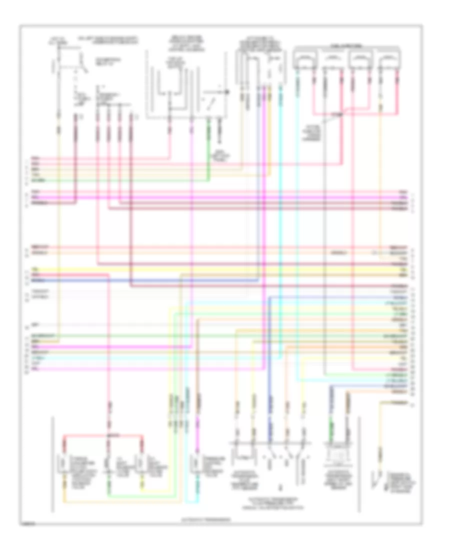
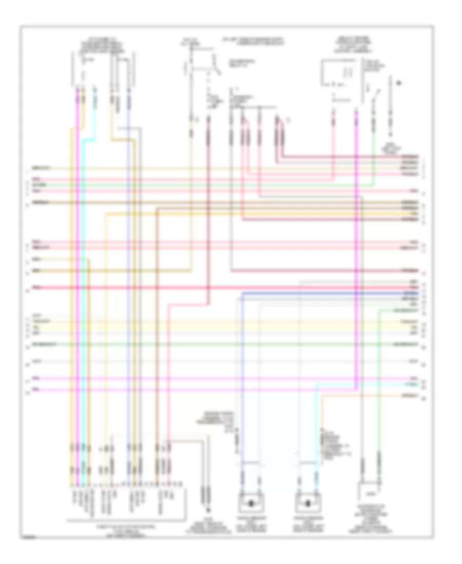
2.2L VIN F, Engine Performance Wiring Diagram (2 of 4) for Chevrolet Malibu LT 2006
List of elements for 2.2L VIN F, Engine Performance Wiring Diagram (2 of 4) for Chevrolet Malibu LT 2006:
- (attached to accelerator pedal) accelerator pedal position (app) sensor
- (below center console shifter) a/t shift lock control solenoid
- (in fuel injector wiring harness)
- (on left side of engine compt) underhood fuse block
- 1-2 shift solenoid (1-2 ss) valve
- 2-3 shift solenoid (2-3 ss) valve
- Automatic transmission
- Automatic transmission fluid pressure (tfp) manual valve position switch
- Automatic transmission fluid temperature (tft) sensor
- Automatic transmission input shaft speed (at iss) sensor
- B11
- C11
- D11
- D12
- Drive
- E11
- Emission 1 fuse 6 10a
- Engine oil pressure (eop) switch (right side of engine)
- Etc fuse 2 15a
- Fuel injectors
- G303 (left kick panel)
- Hot at all times
- Pnk
- Pnk e
- Powertrain relay 33
- Pressure control (pc) solenoid valve
- Red
- Red a
- Rev
- S103
- S130
- Tan
- Tan m
- Tap up/ tap down switch
- Tcc release
- Torque converter clutch pulse width modulation (tcc pwm) solenoid valve
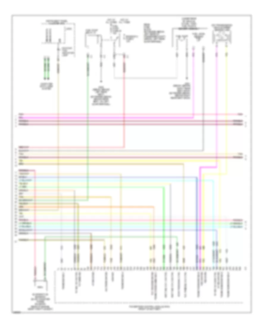
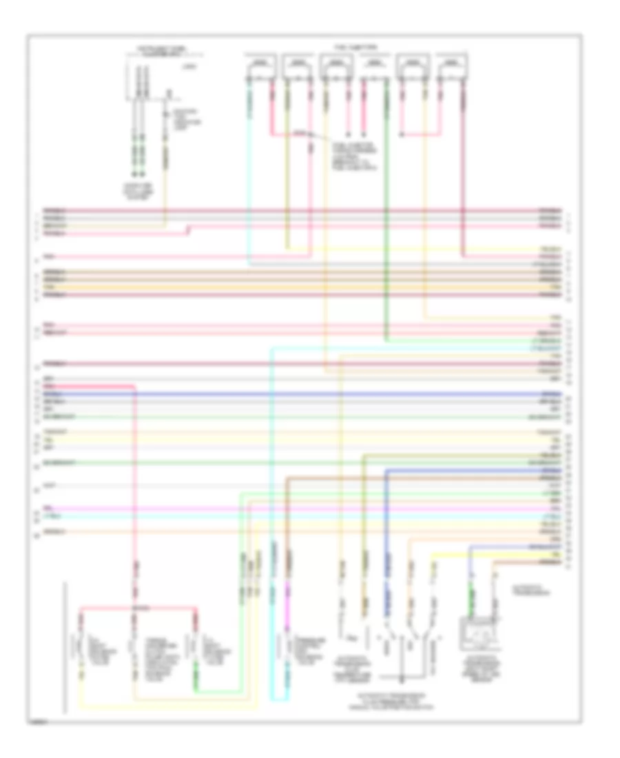
2.2L VIN F, Engine Performance Wiring Diagram (3 of 4) for Chevrolet Malibu LT 2006
List of elements for 2.2L VIN F, Engine Performance Wiring Diagram (3 of 4) for Chevrolet Malibu LT 2006:
- (on transmission) vehicle speed sensor (vss)
- (rear of engine, near throttle body)
- (under rear of vehicle, in fuel tank) fuel pump & sender assembly
- A10
- At iss hi sig
- At iss low sig
- Computer data lines system
- Emission 2 fuse 5 10a
- Evap purge sol ctrl
- Evaporative emission (evap) canister purge solenoid
- Fuel level sensor
- Fuel pump
- Fuel pump fuse 25 15a
- Fuel pump relay 37
- G301 (sedan: behind right rear seat back) (extended sedan: behind right rear seat back)
- G302 (sedan: behind left rear seat) (extended sedan: behind rear seat, on left quarterpanel)
- Gmlan data
- Hot at all times
- Ign
- Instrument panel cluster (ipc)
- Logic
- Low ref
- Malfunc- tion indicator lamp
- Oil press sw sig
- Pc sol vlv hi ctrl
- Pc sol vlv low ctrl
- Pnk
- Powertrain control module (pcm) (front of battery)
- Rear fuse block (extended sedan: left rear of passenger compt) (sedan: left rear quarterpanel)
- Shft sol vlv 1 hi ctrl
- Shft sol vlv 2 hi ctrl
- Tan
- Tcc pwm sol vlv ctrl
- Tcc release sw sig
- Tft sens sig
- Trans press sens sig c
- Trans press sw sig b
- Trans range sw sig b
- Trans range sw sig p
- Trans sw sig a
- Trans sw sig c
- Vss hi sig
- Vss low sig
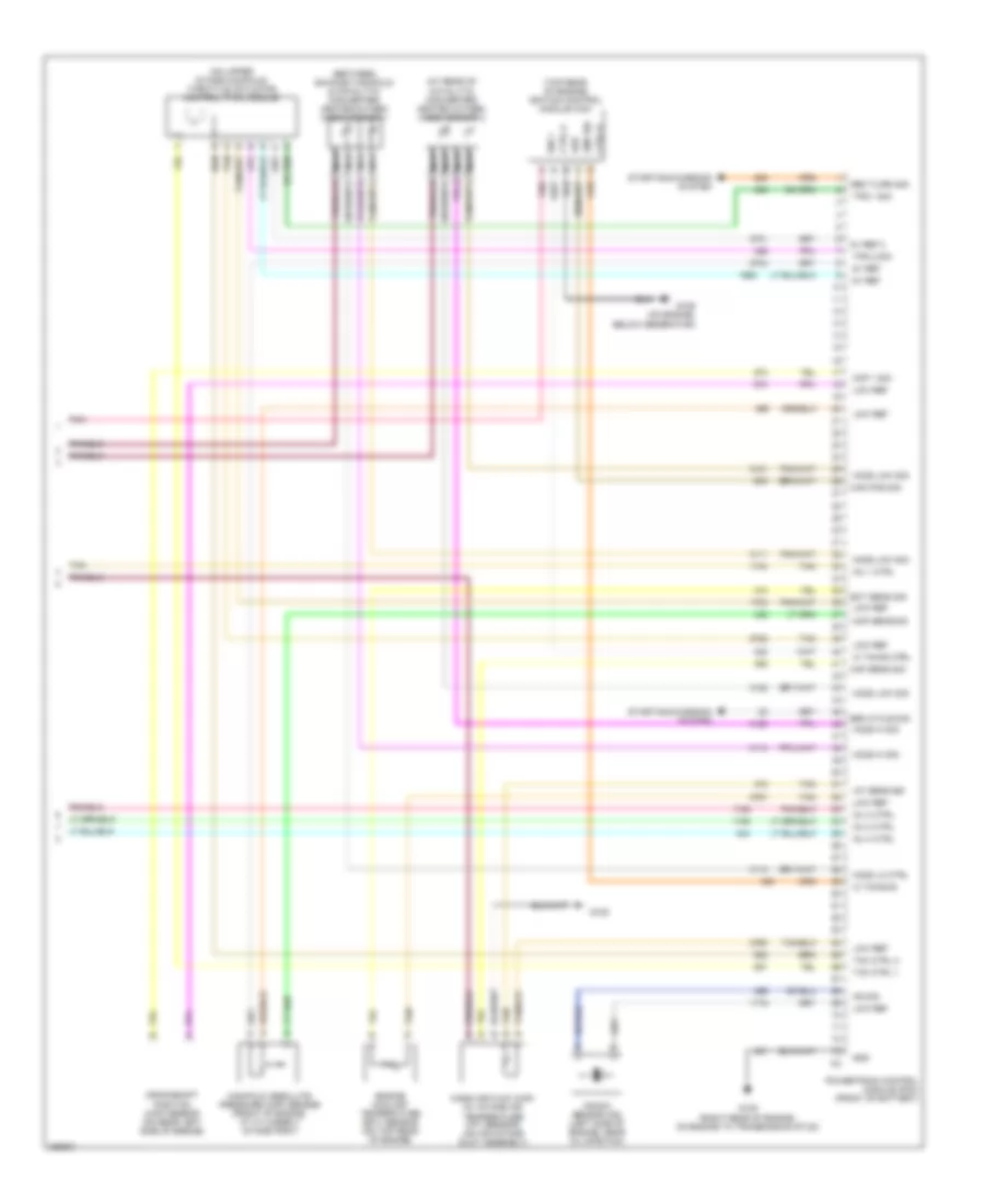
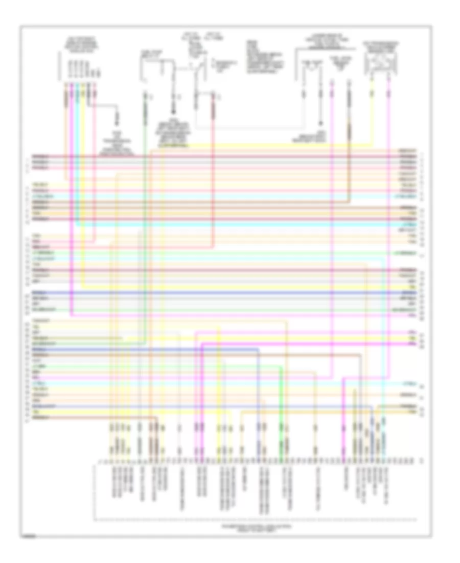
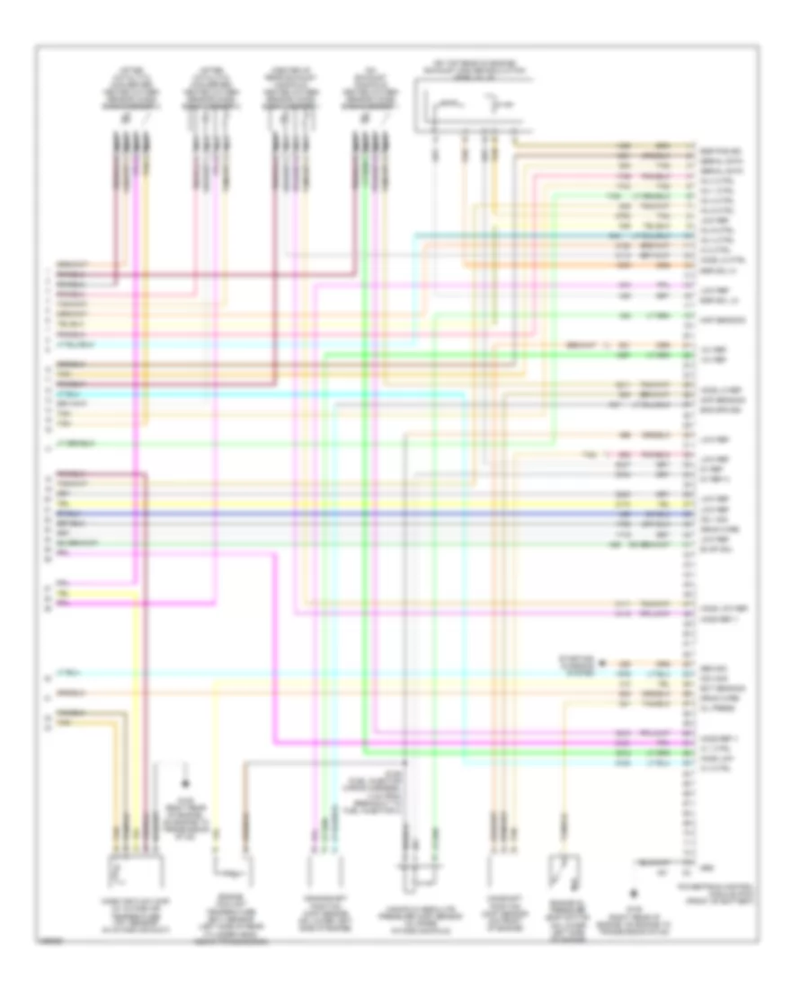
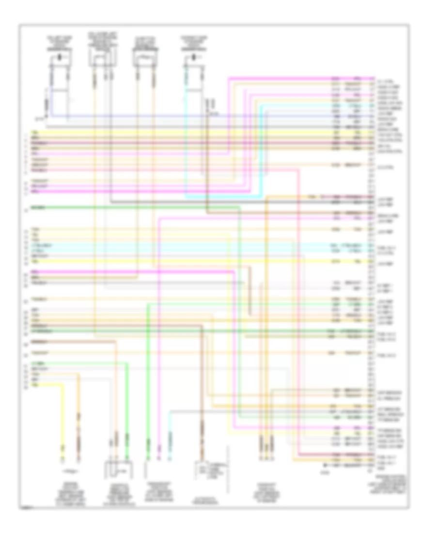
2.2L VIN F, Engine Performance Wiring Diagram (4 of 4) for Chevrolet Malibu LT 2006
List of elements for 2.2L VIN F, Engine Performance Wiring Diagram (4 of 4) for Chevrolet Malibu LT 2006:
- (at rear of catalytic converter) heated oxygen (ho2s) sensor 2
- (between exhaust manifold & catalytic converter) heated oxygen (ho2s) sensor 1
- (on upper intake manifold) throttle actuator control (tac) module
- (top rear of engine) ignition control module (icm)
- 5v ref
- 5v ref 2
- Cam pos sig
- Ckp 1 sig
- Cmp sig
- Crankshaft position (ckp) sensor (on rear left side of engine)
- Ctrl a
- Ctrl b
- Ect sens sig
- Engine coolant temperature (ect) sensor (on top rear of engine)
- G105
- G105 (right rear of engine, on engine to transmission stud)
- G106 (on engine, below generator)
- Gen cycle sig
- Gen tuirn sig
- Gnd
- Grd
- Ho2s hi sig
- Ho2s lo ctrl
- Ho2s low sig
- Iat sens sig
- Ic timing b
- Ic timing ctrl
- Ign 1
- Inj 1 ctrl
- Inj 2 ctrl
- Inj 3 ctrl
- Inj 4 ctrl
- Knock sensor (ks) (left side of engine, near oil dipstick)
- Ks sig
- Low ref
- Maf sens sig
- Manifold absolute pressure (map) sensor (front of engine, at cylinder 3 intake port)
- Map sens sig
- Mass air flow (maf) (w/ intake air temperature (iat) sensor) (on air intake duct assembly)
- Nca
- Pnk
- Powertrain control module (pcm) (front of battery)
- Starting/charging system
- Tac ctrl 1
- Tac ctrl 2
- Tan
- Tps 1 sig
- Tps 2 sig
3.5L VIN 8
3.5L VIN 8, Engine Performance Wiring Diagram (1 of 5) for Chevrolet Malibu LT 2006
List of elements for 3.5L VIN 8, Engine Performance Wiring Diagram (1 of 5) for Chevrolet Malibu LT 2006:
- (on left side of engine compt) underhood fuse block
- (right rear of engine, on engine to transmission stud) g105
- 5v ref 2
- 5v ref a
- A/c refrigerant pressure sensor (left of right front strut tower)
- Acc voltage
- Accy vol
- Air conditioning system
- B10
- Bati vol
- Body control module (bcm) (below right side of dash, near blower motor)
- C10
- Cl rly ctrl
- Computer data lines system
- Cooling fans system
- Crank voltage
- Data link connector (dlc) (below left side of dash, near steering column)
- Evap sol ctrl
- Evaporative emissions (evap) canister vent solenoid (under rear of vehicle, above fuel tank)
- Exterior lights system
- F pmp rly ctrl
- Fan rly ctrl
- Fuel tank pressure (ftp) sensor (under rear of vehicle)
- G109 (near wind- shield wiper fluid reservoir)
- Gmlan data
- Hot at all times
- Hot in run or start
- Ign 1
- Ign 1 fuse 3 15a
- Inj fuse 5 10a
- Logic
- Low ref
- Lvl sens sig
- Mil ctrl
- Park/neutral position (pnp) switch (on top of transmission)
- Pcm fuse 13 10a
- Pcm ign 1 fuse 16 10a
- Pnk
- Powertrain control module (pcm) (front of battery)
- Powertrain ctrl
- Press sens sig
- Rly coil ctrl
- Rly hi ctrl
- Run/ crank fuse 2a
- Run/ crank relay 32
- Serial data
- Starting/ charging system
- Starting/charging system
- Stop lp sig
- Tan
- Tap enable sig
- Tap sw sig
- Trans fuse 4 10a
- Vss speed sig
3.5L VIN 8, Engine Performance Wiring Diagram (2 of 5) for Chevrolet Malibu LT 2006
List of elements for 3.5L VIN 8, Engine Performance Wiring Diagram (2 of 5) for Chevrolet Malibu LT 2006:
- (attached to accelerator pedal) accelerator pedal position (app) sensor
- (below center console shifter) a/t shift lock control assembly
- (engine wiring harness, 7.5 cm from breakout to pcm) s118
- (on left side of engine compt) underhood fuse block
- (rear of engine, near throttle body)
- 5v ref
- App sens 1
- App sens 2
- B11
- Bare
- C11
- Cm from breakout to pcm)
- D11
- E11
- Emission 1 fuse 6 10a
- Etc fuse 2 15a
- Evaporative emissions (evap) canister purge solenoid
- G105 (right rear of engine, on engine to transmission stud)
- G303 (left kick panel)
- Grd
- Hot at all times
- Ign 1
- Knock sensor (ks) 1 (on lower left side of engine)
- Knock sensor (ks) 2 (on lower left side of engine)
- Low ref
- Pnk
- Powertrain relay 33
- S119 (engine wiring harness, 15 bare
- Serial data
- Stop lp sw
- Tan
- Tap up/ tap down switch
- Throttle actuator control (tac) module (on throttle body)
- Vss speed sig
3.5L VIN 8, Engine Performance Wiring Diagram (3 of 5) for Chevrolet Malibu LT 2006
List of elements for 3.5L VIN 8, Engine Performance Wiring Diagram (3 of 5) for Chevrolet Malibu LT 2006:
- (fuel injector wiring harness, 4 cm from breakout to fuel injector 2)
- 1-2 shift solenoid (1-2 ss) valve
- 2-3 shift solenoid (2-3 ss) valve
- Automatic transmission
- Automatic transmission fluid pressure (tfp) manual valve position switch
- Automatic transmission fluid temperature (tft) sensor
- Automatic transmission input shaft speed (at iss) sensor
- Computer data lines system
- Drive
- Fuel injectors
- Gmlan data
- Ign
- Instrument panel cluster (ipc)
- Logic
- Malfunc- tion indicator lamp
- Pnk
- Pnk e
- Pressure control (pc) solenoid valve
- Red
- Red a
- Rev
- S103
- S130
- Tan
- Tan m
- Tcc release
- Torque converter clutch pulse width modulation (tcc pwm) solenoid valve
3.5L VIN 8, Engine Performance Wiring Diagram (4 of 5) for Chevrolet Malibu LT 2006
List of elements for 3.5L VIN 8, Engine Performance Wiring Diagram (4 of 5) for Chevrolet Malibu LT 2006:
- (on top right side of engine) ignition control module (icm)
- (on transmission) vehicle speed sensor (vss)
- (under rear of vehicle, in fuel tank) fuel pump & sender assembly
- 1-2 sol vlv ctrl
- 2-3 sol vlv ctrl
- A10
- At iss hi sig
- At iss low sig
- Emission 2 fuse 5 10a
- Fuel level sensor
- Fuel pump
- Fuel pump fuse 25 15a
- Fuel pump relay 37
- G106 (on transmission, near park/neutral position switch)
- G301 (behind right rear seat back)
- G302 (sedan: behind left rear seat) (extended sedan: behind rear seat, on left quarterpanel)
- Grd
- Ho2s hi sig (1/2)
- Ho2s hi sig (2/2)
- Ho2s lo ctrl (1/2)
- Ho2s lo ctrl (2/2)
- Ho2s lo sig (1/2)
- Ho2s lo sig (2/2)
- Hot at all times
- Iat sens sig
- Ic 1 ctrl
- Ic 2 ctrl
- Ic 3 ctrl
- Ign 1
- Low ref
- Maf sens sig
- Pc sol vlv hi ctrl
- Pc sol vlv lo ctrl
- Pnk
- Powertrain control module (pcm) (front of battery)
- Rear fuse block (extended sedan: left rear of passenger compt) (sedan: left rear quarterpanel)
- Tan
- Tcc pwm sol vlv ctrl
- Tcc release sw sig
- Tft sens sig
- Trans press sens sig b
- Trans press sens sig c
- Trans range sw sig a
- Trans range sw sig b
- Trans range sw sig c
- Trans range sw sig p
- Vss high sig
- Vss low sig
3.5L VIN 8, Engine Performance Wiring Diagram (5 of 5) for Chevrolet Malibu LT 2006
List of elements for 3.5L VIN 8, Engine Performance Wiring Diagram (5 of 5) for Chevrolet Malibu LT 2006:
- (after catalytic converter) heated oxygen sensor (ho2s) bank 1 sensor 2
- (after catalytic converter) heated oxygen sensor (ho2s) bank 2 sensor 2
- (center of rear exhaust manifold) heated oxygen sensor (ho2s) bank 1 sensor 1
- (on exhaust manifold) heated oxygen sensor (ho2s) bank 2 sensor 1
- (on top rear of engine) exhaust gas recirculation (egr) valve
- 12v ref
- 5v ref
- 5v ref a
- A tan
- Camshaft position (cmp) sensor (on front of engine)
- Cmp sens sig
- Crankshaft position (ckp) sensor (on lower left side of engine)
- Drain wire
- Ect sens sig
- Egr pos sig
- Egr sol hi
- Egr sol lo
- Eng spd sig
- Engine coolant temperature (ect) sensor (left side of rear cylinder head, above transmission)
- Engine oil pressure (eop) switch (on lower left side of engine)
- Evap sol
- G105 (right rear of engine, on engine to transmission stud)
- Gen sig
- Grd
- Ho2s lo ctrl
- Ho2s lo ref
- Ho2s low
- Ho2s low ref
- Ho2s ref v
- Ic 1 ctrl
- Ic 2 ctrl
- Ic 3 ctrl
- Inj 1 ctrl
- Inj 2 ctrl
- Inj 3 ctrl
- Inj 4 ctrl
- Inj 5 ctrl
- Inj 6 ctrl
- Ks 1 sig
- Ks 2 sig
- Low ref
- Manifold absolute pressure (map) sensor (in upper intake manifold)
- Map sens sig
- Mass air flow (maf) (w/ intake air temperature (iat) sensor) (in intake air duct)
- Nca
- Oil press
- Powertrain control module (pcm) (front of battery)
- S106 (fuel injector wiring harness, 3 cm from breakout to fuel injector 3)
- Serial data
- Starting/ charging system
- Tan
3.9L VIN 1
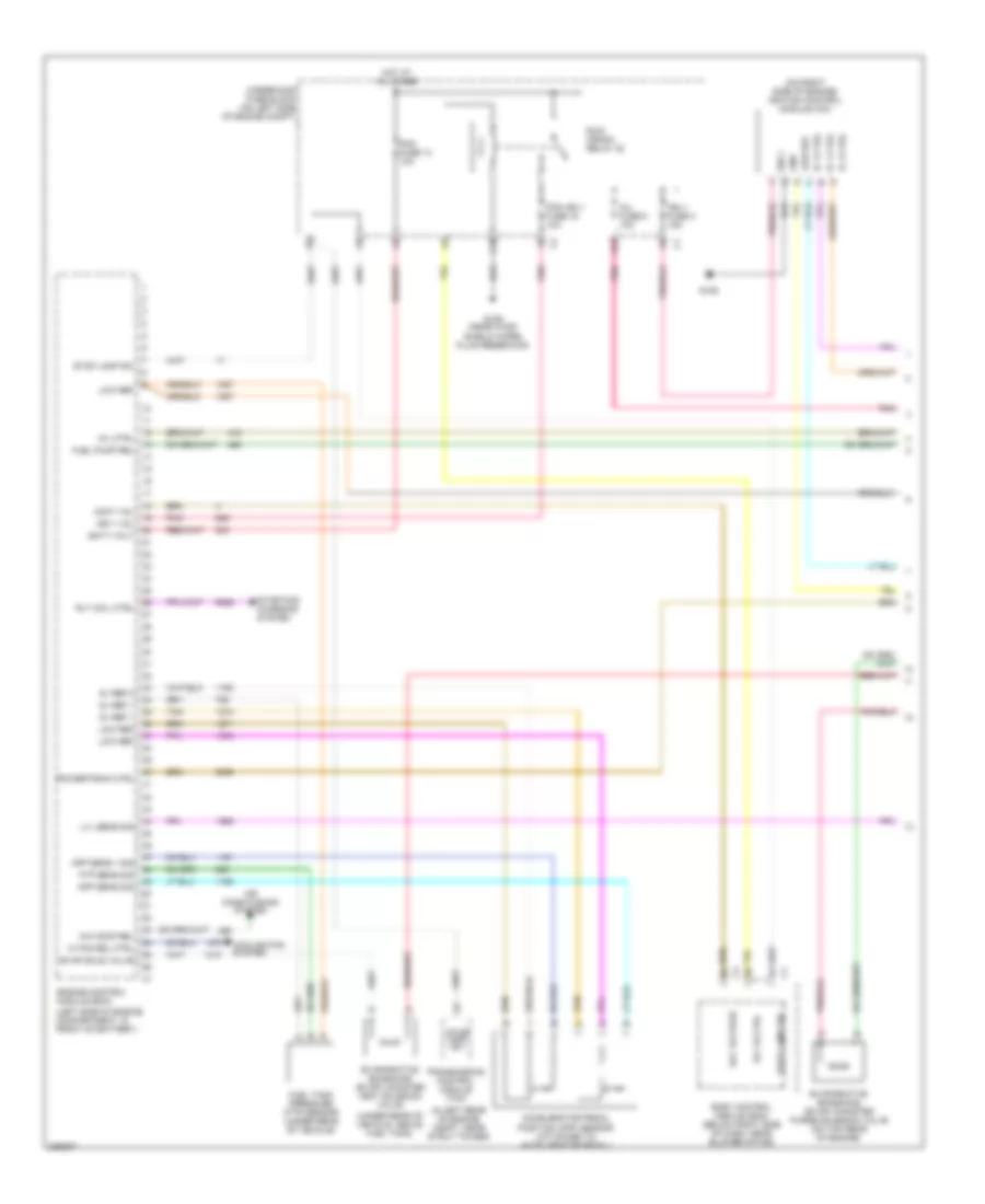
3.9L VIN 1, Engine Performance Wiring Diagram (1 of 4) for Chevrolet Malibu LT 2006
List of elements for 3.9L VIN 1, Engine Performance Wiring Diagram (1 of 4) for Chevrolet Malibu LT 2006:
- (in left rear of engine compt, near strut tower)
- (left side of engine compartment, in front of battery)
- (on right side of engine) ignition control module (icm)
- (under rear of vehicle, above fuel tank)
- 5v ref 1
- 5v ref 2
- A/c comp rel
- Acc voltage
- Accelerator pedal position (app) sensor (attached to accelerator pedal)
- Accy vol
- Air conditioning system
- App sens 1 sig
- App sens sig
- B10
- Batt volt
- Body control module (bcm) (below right side of dash, near blower motor)
- C10
- Cooling fan system
- Engine control module (ecm)
- Evap sole valve
- Evaporative emissions (evap) canister purge solenoid valve (on top rear of engine)
- Evaporative emissions (evap) canister vent solenoid valve
- Ftp sens sig
- Fuel pump rel
- Fuel tank pressure (ftp) sensor (under rear of vehicle)
- G106
- G109 (near wind- shield wiper fluid reservoir)
- Gnd e
- Hi fan rel ctrl
- Hot at all times
- Ic 1 ctrl b
- Ic 2 ctrl a
- Ic 3 ctrl c
- Ign 1 f
- Ign 1 fuse 3 15a
- Ign 1 vol
- Inj fuse 5 10a
- Low ref
- Low ref d
- Lvl sens sig
- Mil ctrl
- Pcm fuse 13 10a
- Pcm ign 1 fuse 16 10a
- Pnk
- Powertrain ctrl
- Rly coil ctrl
- Rly hi ctrl
- Run/ crank relay 32
- Starting/ charging system
- Stop lamp sw
- Tan
- Tan c
- Transmission control module (tcm)
- Underhood fuse block (on left side of engine compt)
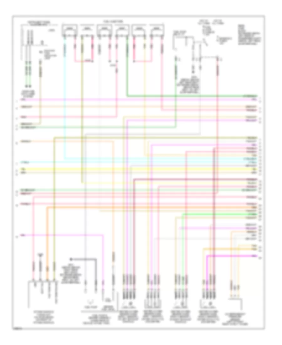
3.9L VIN 1, Engine Performance Wiring Diagram (2 of 4) for Chevrolet Malibu LT 2006
List of elements for 3.9L VIN 1, Engine Performance Wiring Diagram (2 of 4) for Chevrolet Malibu LT 2006:
- (after catalytic) converter)
- (sedan: behind left rear seat) (extended sedan: behind rear seat, on left quarterpanel)
- A/c refrigerant pressure sensor (left of right front strut tower)
- A10
- Batt vol
- Computer data lines system
- Emission 2 fuse 5 10a
- Fuel injectors
- Fuel pump
- Fuel pump & sender assembly (under rear of
- Fuel pump fuse 25 15a
- Fuel pump relay 37
- G105
- G301 (sedan: behind right rear seat back) (extended sedan: behind rear seat, on left quarterpanel)
- G302
- Gmlan data
- Gnd
- Heated oxygen sensor (ho2s) bank 1 sensor 1 (in left exhaust manifold)
- Heated oxygen sensor (ho2s) bank 1 sensor 2 (after catalytic) converter)
- Heated oxygen sensor (ho2s) bank 2 sensor 1 (in right exhaust manifold)
- Heated oxygen sensor (ho2s) bank 2 sensor 2
- Hot at all times
- Ign
- Instrument panel cluster (ipc)
- Intake manifold tuning (imt) valve solenoid (on front of intake manifold)
- Logic
- Malfunc- tion indicator lamp
- Nca
- Nca nca
- Pnk
- Rear fuse block (extended sedan: left rear of passenger compt) (sedan: left rear quarterpanel)
- S130
- Sensor fuel level
- Tan
- Var turn pos sig
- Var turn sig
- Vehicle, in fuel tank)
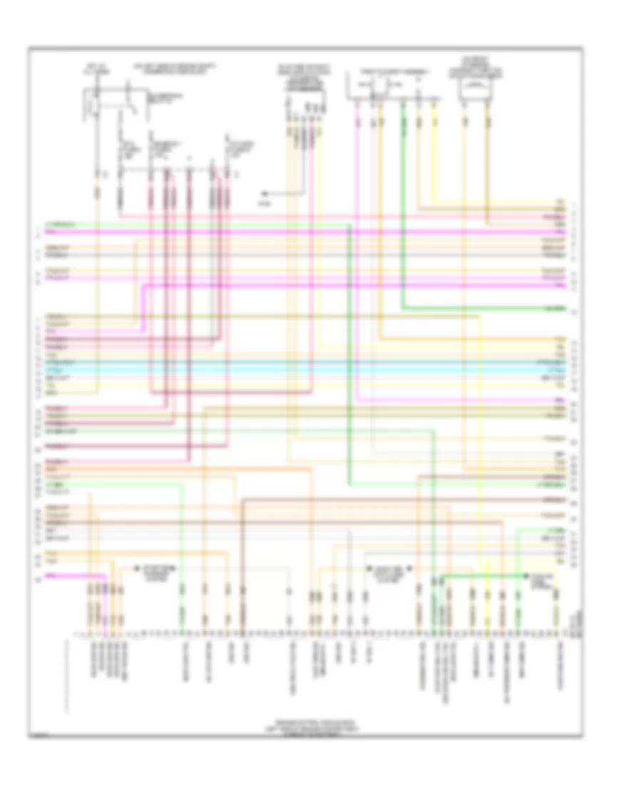
3.9L VIN 1, Engine Performance Wiring Diagram (3 of 4) for Chevrolet Malibu LT 2006
List of elements for 3.9L VIN 1, Engine Performance Wiring Diagram (3 of 4) for Chevrolet Malibu LT 2006:
- (65 to 73
- (in intake air duct) mass air flow (maf)/ intake air temperature (iat) sensor
- (left side of engine compartment, in front of battery)
- (on front of engine) camshaft position actuator solenoid
- (on left side of engine compt) underhood fuse block
- 5v ref 1
- 5v ref 2
- A/c pressure sens sig
- B11
- C11
- Computer data lines system
- Cooling fans system
- D11
- E11
- Ect sens sig
- Emission 1 fuse 6 10a
- Engine control module (ecm)
- Etc fuse 2 15a
- Evap pur sol ctrl
- G105
- Gen field cycle sig
- Gen tur on sig
- Gmlan data +
- Gmlan data -
- Gnd
- Ho2s hi sig
- Ho2s low ctrl
- Ho2s low sig
- Hot at all times
- Ign
- Imtv/dod fuse 45 10a
- Low ref
- Low sped fan rel ctrl
- Map sens sig
- Not used)
- Oil levl sw sig
- Park/neutral sig
- Powertrain relay 33
- Sig
- Starting/ charging system
- Tan
- Throttle body assembly
- Vari turn pos sig
- Vari turn sig
3.9L VIN 1, Engine Performance Wiring Diagram (4 of 4) for Chevrolet Malibu LT 2006
List of elements for 3.9L VIN 1, Engine Performance Wiring Diagram (4 of 4) for Chevrolet Malibu LT 2006:
- (in bottom of oil pan) engine oil level sensor
- (on left side of engine) knock sensor (ks 1)
- (on lower left side of engine) engine oil pressure (eop) sensor
- (on right side of engine) knock sensor (ks 2)
- 5v ref 1
- 5v ref 2
- Automatic transmission
- Bare
- Bare s119
- Cam pos ctrl
- Camshaft position (cmp) sensor (on top front of engine)
- Cmp sens sig
- Crankshaft position (ckp) sensor (in lower left side of engine)
- Drain wire
- Engine control module (ecm) (left side of engine compartment, in front of battery)
- Engine coolant temperature (ect) sensor (on rear of left cylinder head)
- Fuel inj 1
- Fuel inj 2
- Fuel inj 3
- Fuel inj 4
- Fuel inj 5
- Fuel inj 6
- G105
- Gnd
- Ho2s hi sig
- Ho2s lo ref
- Ho2s low ctr
- Ho2s low ref
- Ho2s low sig
- Iat sens sig
- Ic 1 ctrl
- Ic 2 ctrl
- Ic 3 ctrl
- Ign vol
- Internal mode switch (ims)
- Knock sens2
- Knock sig
- Low ref
- Maf sens sig
- Manifold absolute pressure (map) sensor (on top of intake manifold)
- Oil pres sig
- P/n sig
- Rsol sped sig
- S118
- Tac mot ctrl
- Tac mtr ctrl
- Tan
- Tp sens sig
- Tp sens2 sig
EXTERIOR LIGHTS
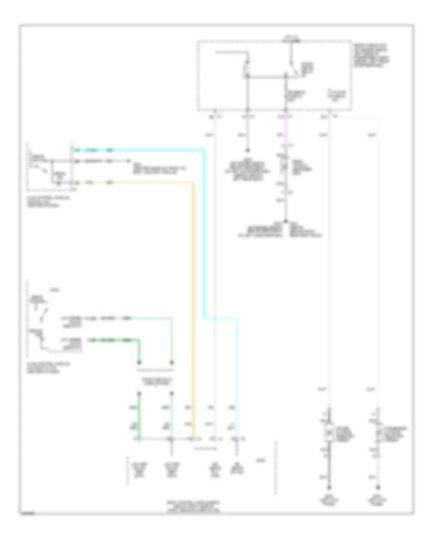
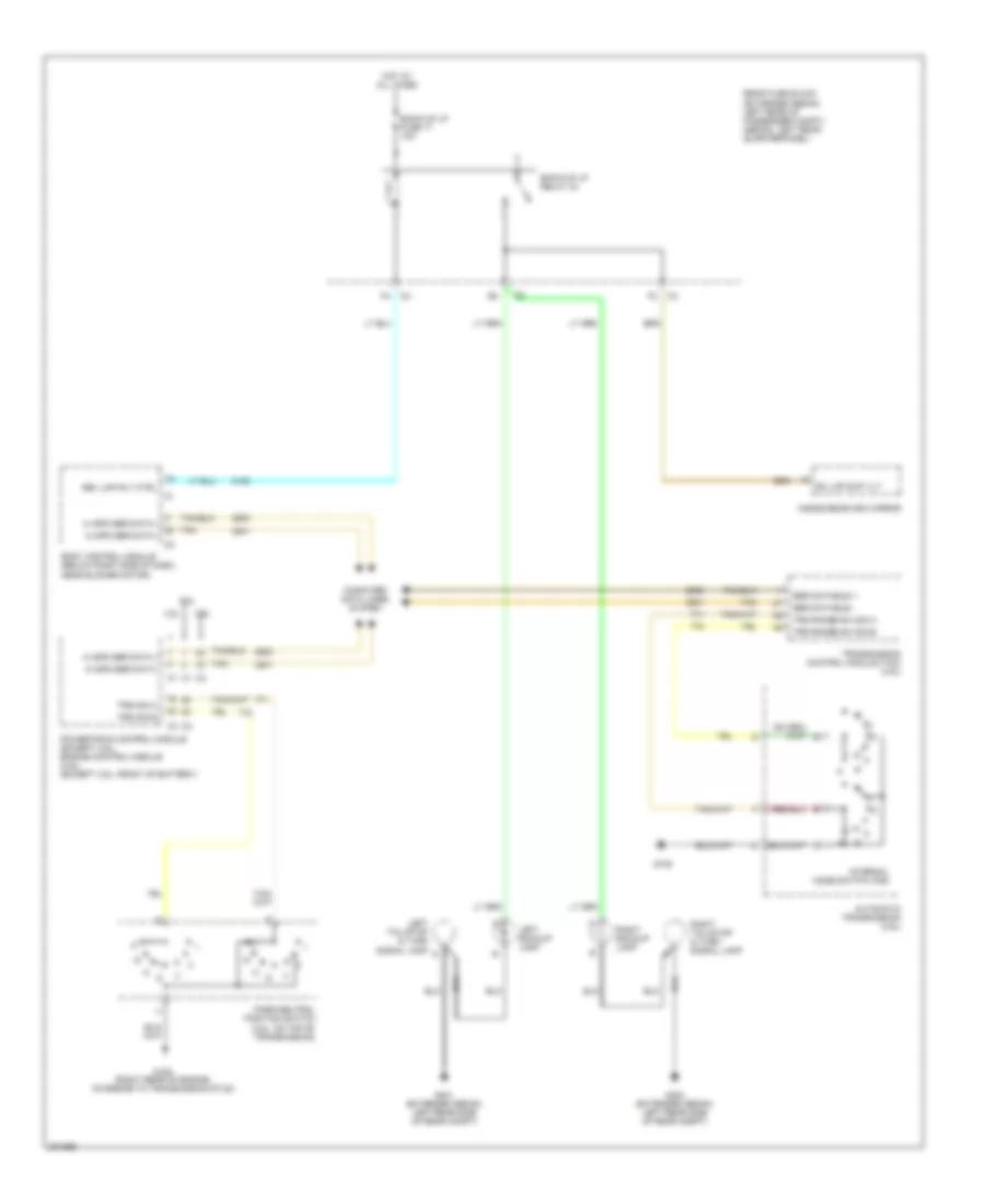
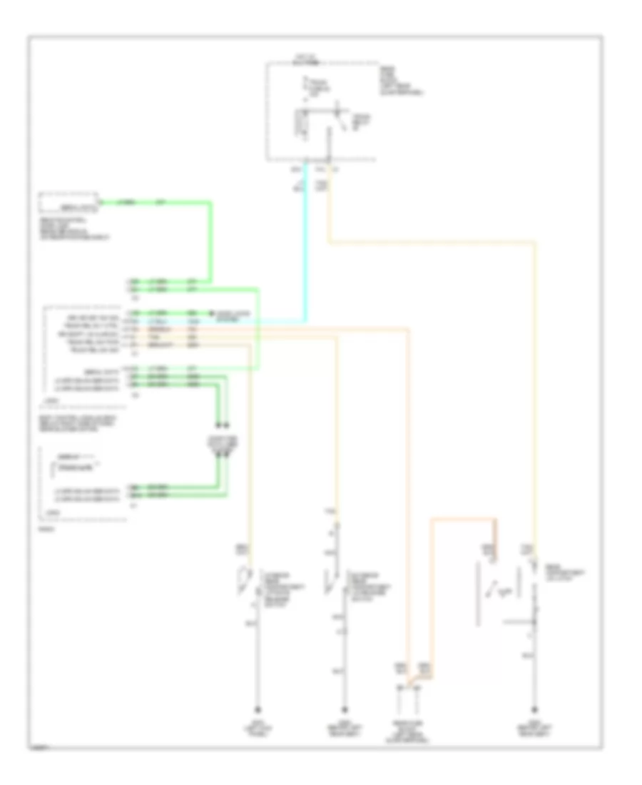
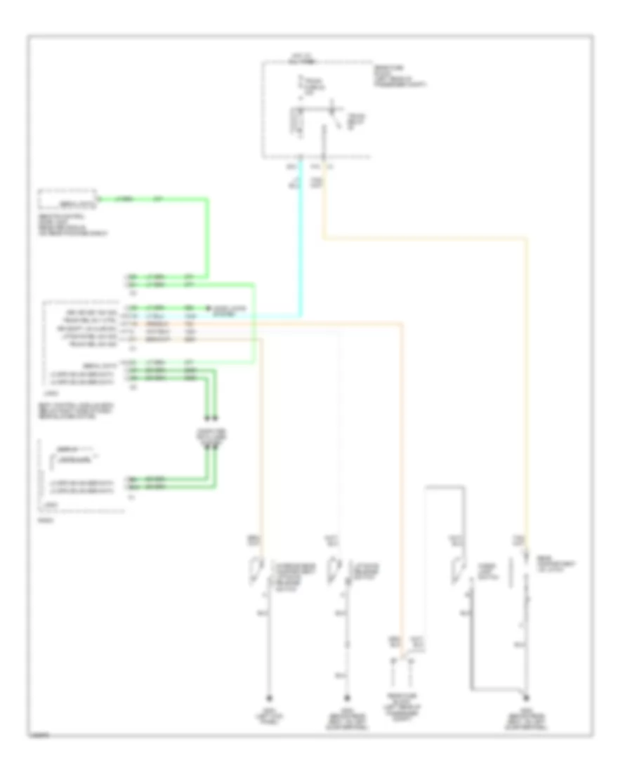
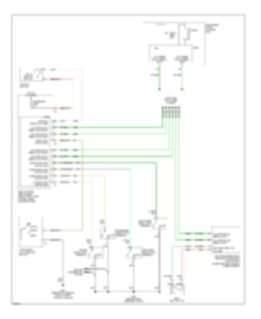
Back-up Lamps Wiring Diagram for Chevrolet Malibu LT 2006
List of elements for Back-up Lamps Wiring Diagram for Chevrolet Malibu LT 2006:
- 2.2l
- 3.5l
- 3.9l
- Automatic transmission (3.9l)
- Back-up lp fuse 17 10a
- Back-up lp relay 33
- Body control module (below right side of dash, near blower motor)
- Bu lmp sup vlt
- Computer data lines system
- G105
- G105 (right rear of engine, on engine to transmission stud)
- G401 (extended sedan: left rear side of rear compt)
- G403 (extended sedan: left rear side of rear compt)
- Hi spd ser data +
- Hi spd ser data -
- Hot at all times
- Inside rearview mirror
- Internal mode switch (ims)
- Left backup lamp
- Left tail/stop & turn signal lamp
- Park/neutral position switch (3.5l: on top of transmission)
- Powertrain control module (except 3.9l) engine control module (3.9l) (except 3.9l: front of battery)
- Rear fuse block (extended sedan: left rear of passenger compt) (sedan: left rear quarterpanel)
- Rev lmp rly ctrl
- Right backup lamp
- Right tail/stop & turn signal lamp
- Ser data bus +
- Ser data bus -
- Tan
- Transmission control module (tcm) (3.9l)
- Trs range sw sig a
- Trs range sw sig b
- Trs sig a
- Trs sig b
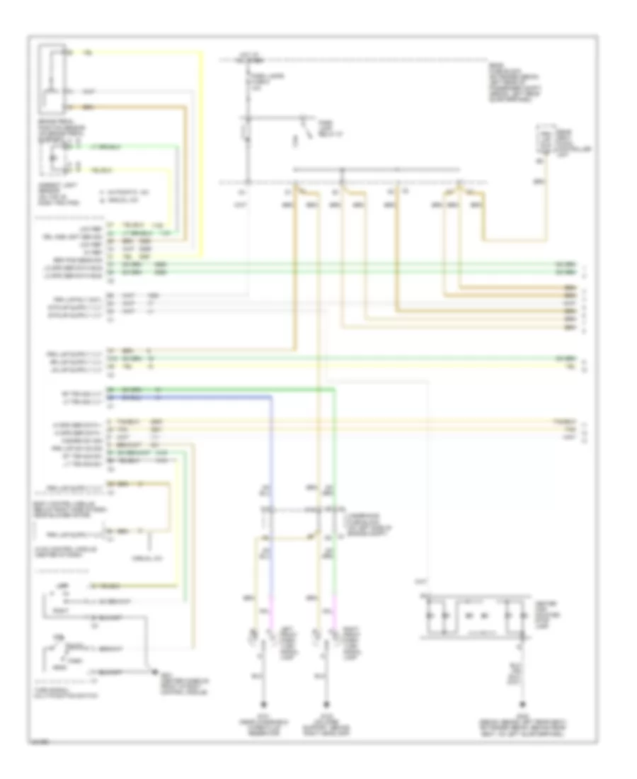
Exterior Lamps Wiring Diagram (1 of 2) for Chevrolet Malibu LT 2006
List of elements for Exterior Lamps Wiring Diagram (1 of 2) for Chevrolet Malibu LT 2006:
- 5v ref
- A d
- A12
- Ambient light sensor (on top of dash trim pad)
- Auto
- Automatic a/c a
- B a
- B b
- Body control module (below right side of dash, near blower motor)
- Brake pedal position sensor (on brake pedal support)
- Brk pos sens sig
- C12
- Center high mounted stop lamp
- Drl amb lght sen sig
- F11
- G101 (near windshield wiper fluid reservoir)
- G102 (on core support, behind right headlamp)
- G201 (center console, front of body control module)
- G302 (sedan: behind left rear seat) (extended sedan: behind rear seat, on left quarterpanel)
- Hazard sw sig
- Head
- Hi spd ser data +
- Hi spd ser data -
- Hot at all times
- Hvac control module (center of dash)
- Left
- Left front park/ turn signal lamp
- Lf trn sig vlt
- Lo spd ser data bus
- Low ref
- Lt trn sig sw
- Manual a/c
- Manual a/c b
- Off
- Park
- Park lamp relay 27
- Park lamps fuse 6 10a
- Prk lmp rly cntl
- Prk lmp sup vlt
- Prk lmp sw on sig
- Rear fuse block (extended sedan: left rear of passenger compt) (sedan: left rear quarterpanel)
- Rear seat audio controller unit
- Rf trn sig vlt
- Right
- Right front park/ turn signal lamp
- Rt trn sig sw
- Tan
- Turn signal/ multi-function switch
- Underhood fuse block (on left side of engine compt)
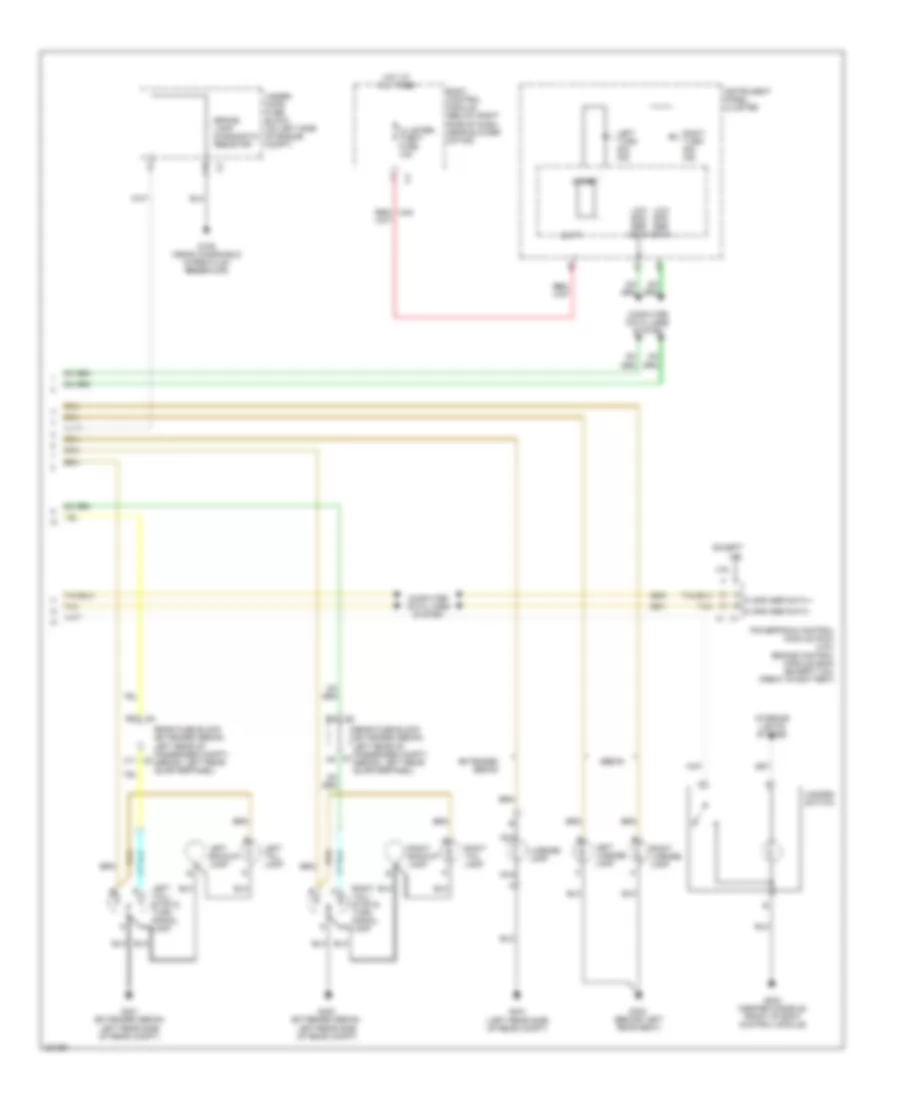
Exterior Lamps Wiring Diagram (2 of 2) for Chevrolet Malibu LT 2006
List of elements for Exterior Lamps Wiring Diagram (2 of 2) for Chevrolet Malibu LT 2006:
- 3.9l
- Batt
- Body control module (below right side of dash, near blower motor)
- Brake lamp diagnostic resistor
- C10
- C11
- Chime
- Cluster/ theft fuse 10a
- Computer data lines system
- Except 3.9l
- Extended sedan
- G109 (near windshield wiper fluid reservoir)
- G203 (center console, front of body control module)
- G302 (behind left rear seat)
- G401 (extended sedan: left rear side of rear compt)
- G401 (left rear side of rear compt)
- G403 (extended sedan: left rear side of rear compt)
- Hazard switch
- Hi spd ser data +
- Hi spd ser data -
- Hot at all times
- Instrument panel cluster
- Interior lights system
- Left backup lamp
- Left license lamp
- Left tail lamp
- Left tail/ stop & turn signal lamp
- Left turn sig ind
- License lamp
- Low spd ser data
- Nca
- Powertrain control module (pcm) (3.9l) engine control module (ecm) (except 3.9l) (front of battery)
- Rear fuse block (extended sedan: left rear of passenger compt) (sedan: left rear quarterpanel)
- Red/
- Right backup lamp
- Right license lamp
- Right tail lamp
- Right tail/ stop & turn signal lamp
- Right turn sig ind
- Sedan
- Tan
- Under- hood fuse block (on left side of engine compt)
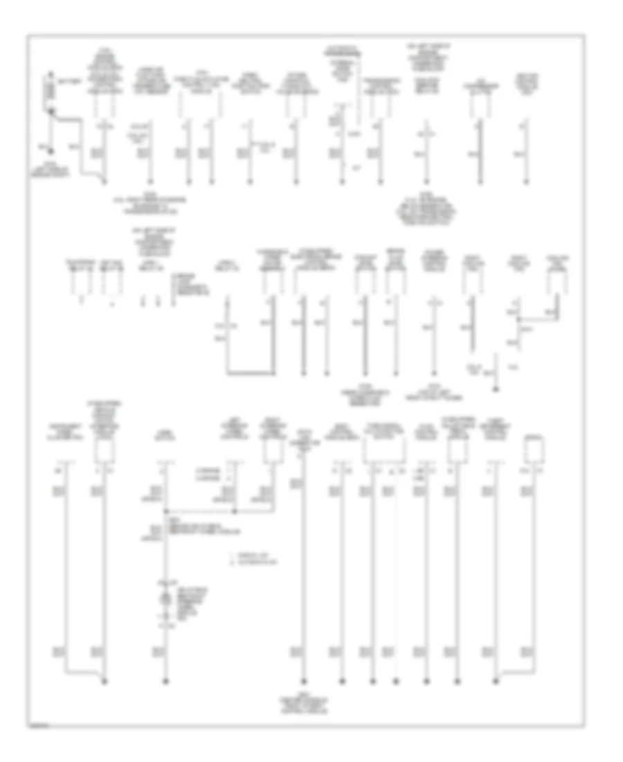
GROUND DISTRIBUTION
Ground Distribution Wiring Diagram (1 of 4) for Chevrolet Malibu LT 2006
List of elements for Ground Distribution Wiring Diagram (1 of 4) for Chevrolet Malibu LT 2006:
- (3 spoke)
- (3.5l & c
- (3.5l)
- (3.9l) engine control module (ecm) (2.2l & 3.5l) powertrain control module (pcm)
- (4 spoke)
- (if equipped) adjustable pedal module
- (if equipped) electronic brake control module (ebcm)
- (if equipped) vehicle communi- cation interface module (vcim)
- (on left side of engine compartment) underhood fuse block
- (on left side of engine compartment) underhood fuse block
- 2.2l
- 3.5l & 2.2l
- 3.5l & 3.9l
- 3.9l)
- A c1
- A/c compressor clutch
- A/t
- A12
- Automatic a/c
- Automatic transmission
- B (2.2l)
- Battery
- Body control module (bcm)
- Brake fluid level switch
- Brake lamp diagnostic resistor 46
- C10
- C100
- Cool/fan ser/par relay 29
- Coolant level switch
- Cooling fan diode
- Data link connector (dlc)
- Frt fog relay 36
- G103 (top of left front strut tower)
- G104 (left side of engine compt)
- G105 (3.5l: right rear of engine, on engine to transmission stud)
- G106 (2.2l: on engine, below generator) (3.5l: on transmission, near park/neutral position switch)
- G109 (near windshield wiper fluid reservoir)
- G201 (center console, front of body control module)
- Horn switch
- Hvac control module
- Ignition control module (icm)
- Inflatable restraint steering wheel module coil
- Instrument panel cluster (ipc)
- Intake manifold tuning (imt) valve solenoid
- Internal mode switch (ims)
- Left steering wheel controls
- Manual a/c
- Mass air flow (maf)/ intake air temperature (iat) sensor
- Park/ neutral position (pnp) switch
- Power steering control module
- Radio
- Right cooling fan
- Right steering wheel controls
- Run/crank relay 32
- S101
- S201 (behind inflatable restraint wheel module)
- Theft deterrent control module
- Throttle actuator control (tac) module
- Transmission control module (tcm)
- Turn signal/ multifunction switch
- Windshield wiper motor assembly
- Wpr 1 relay 39
- Wpr 2 relay 40
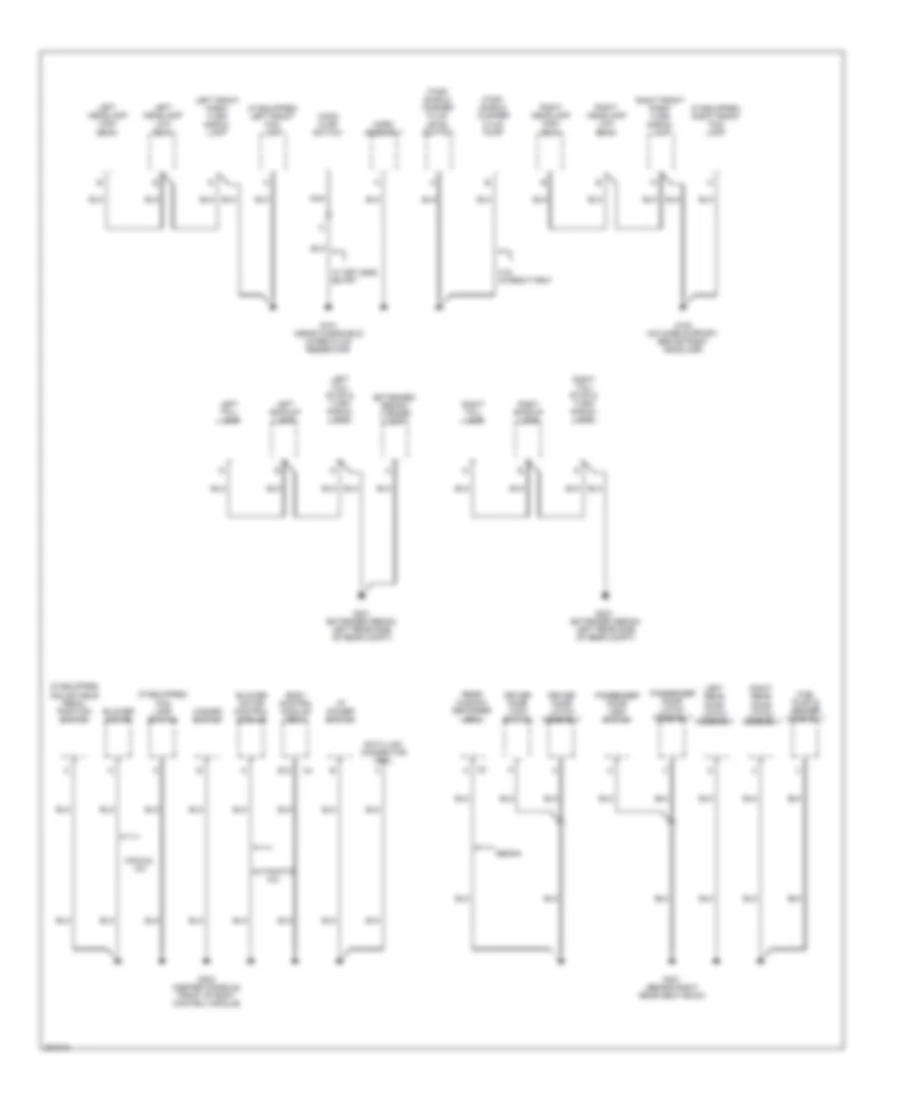
Ground Distribution Wiring Diagram (2 of 4) for Chevrolet Malibu LT 2006
List of elements for Ground Distribution Wiring Diagram (2 of 4) for Chevrolet Malibu LT 2006:
- (extended sedan) license lamp
- (extended sedan: left rear side of rear compt)
- (if equipped) adjustable pedal position switch
- (if equipped) fog lamp switch
- (if equipped) left front fog lamp
- (if equipped) right front fog lamp
- Automatic a/c
- Blower motor
- Blower motor control module
- Body control module (bcm)
- Data link connector (dcl)
- Driver door latch assembly
- Driver door lock switch
- E12
- Fuel pump & sender assembly
- G101 (near windshield wiper fluid reservoir)
- G102 (on core support, behind right headlamp)
- G203 (center console, front of body control module)
- G301 (behind right rear seat back)
- G401 (extended sedan: left rear side of rear compt)
- G403
- Hazard switch
- Hood ajar switch
- Horn assembly
- I/p dimmer switch
- Left backup lamp
- Left front park/ turn signal lamp
- Left headlamp high beam
- Left headlamp low beam
- Left rear door latch assembly
- Left tail- lamp
- Left tail/ stop & turn signal lamp
- Manual a/c
- Nca
- Passenger door latch assembly
- Passenger door lock switch
- Rear window defogger grid
- Right backup lamp
- Right front park/ turn signal lamp
- Right headlamp high beam
- Right headlamp low beam
- Right rear door latch assembly
- Right tail- lamp
- Right tail/ stop & turn signal lamp
- Sedan
- W/ keyless entry
- W/o intermittent
- Wind- shield washer fluid level switch
- Wind- shield washer fluid pump
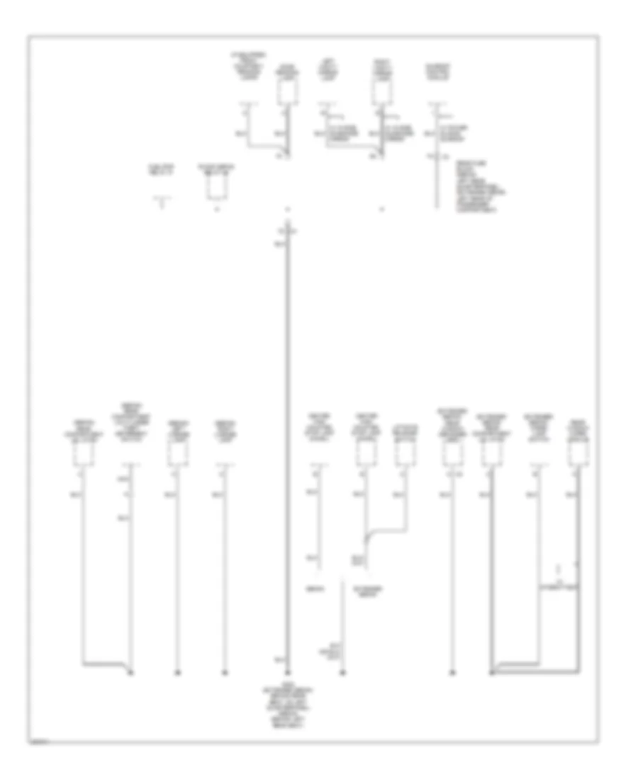
Ground Distribution Wiring Diagram (3 of 4) for Chevrolet Malibu LT 2006
List of elements for Ground Distribution Wiring Diagram (3 of 4) for Chevrolet Malibu LT 2006:
- (extended sedan) cargo lamp switch
- (extended sedan) rear compartment lid latch
- (extended sedan) rear window defogger grid
- (if equipped) front courtesy/ reading lamps
- (sedan) left license lamp
- (sedan) rear compartment lid cylinder theft deterrent switch
- (sedan) rear compartment lid latch
- (sedan) right license lamp
- Center high mounted stop lamp (chmsl)
- Dome reading lamp
- Extended sedan
- Fuel/pmp relay 37
- G302 (extended sedan: behind rear seat, on left quarterpanel) (sedan: behind left rear seat)
- Left vanity mirror lamp
- Liftgate release switch
- Mirror
- Nca
- R/wdo defog relay 26
- Rear fuse block (sedan: left rear quarterpanel) (extended sedan: left rear of passenger compartment)
- Rear window wiper module
- Right vanity mirror lamp
- Sedan
- Sunroof
- Sunroof control module
- W/ intermittent
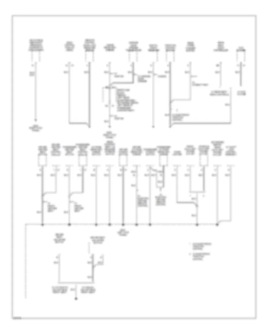
Ground Distribution Wiring Diagram (4 of 4) for Chevrolet Malibu LT 2006
List of elements for Ground Distribution Wiring Diagram (4 of 4) for Chevrolet Malibu LT 2006:
- (extended sedan) rear auxiliary power outlet
- (left kick panel)
- (right kick panel)
- A/t shift lock control assembly
- Body control module (bcm)
- Cigar lighter
- Console auxiliary power outlet
- Digital radio receiver
- Driver heated seat control module
- Driver heated seat switch
- Driver outside rearview mirror
- Driver seat adjuster switch
- Driver window switch
- Dvd player
- Front auxiliary power outlet
- G303
- G304 (right kick panel)
- G305
- Garage door opener transmitter
- Inflatable restraint sensing & diagnostic module (sdm)
- Inside rearview mirror
- Nca
- Outside rearview mirror switch
- Passenger compartment)
- Passenger heated seat control module
- Passenger heated seat switch
- Passenger outside rearview mirror
- Passenger window switch
- Rear compart- ment lid release interior switch
- Rear fuse block (sedan: left rear quarterpanel) (extended sedan: left rear of c1
- Rear seat audio controller
- Rear wiper washer switch
- Remote control door lock receiver (rcdlr)
- S band
- Traction control switch
- W/ electric heated remote control
- W/ front heater seat
- W/ automatic adjustable front seat
- W/ dvd player
- W/ electric heated remote control
- W/ electronic traction control
- W/ garage door opener
- W/ intermittent
- W/ manual adjustable front seat
- W/ onstar
- W/ rear seat radio controls
- W/o electronic traction control
HEADLIGHTS
Headlights Wiring Diagram for Chevrolet Malibu LT 2006
List of elements for Headlights Wiring Diagram for Chevrolet Malibu LT 2006:
- (center console, front of body control module)
- A12
- Ambient light sensor (on top of dash trim pad)
- Auto
- B12
- Body control module (below right side of dash, near blower motor)
- C10
- Computer data lines system
- D10
- Drl fuse 46 15a
- Drl relay
- Drl rly ctrl
- F12
- F2 c2
- Fog lamp switch
- Fog lmp rly ctrl
- Fog lmp sw sig
- Frt fog lp fuse 10 10a
- Frt fog relay
- Ftp
- Ftp sw sig
- G101 (near wind- shield wiper fluid reservoir)
- G102 (on core support, behind right headlamp)
- G109 (near wind- shield wiper fluid reservoir)
- G201 (center console, front of body control module)
- G203
- Hdlmps off
- Hdlmps on
- Head
- Headlamp dimmer sw hi bm sig
- High
- High beam in
- High beam ind
- High beam relay
- Hot at all times
- Instrument panel cluster
- Left front fog lamp
- Left high beam headlamp
- Left low beam headlamp
- Lh high fuse 11 10a
- Lh low fuse 7 10a
- Logic
- Low
- Low beam in
- Low beam relay
- Lt sen low ref
- Lt sen sig
- Off
- Park
- Rh high fuse 12 10a
- Rh low fuse 9 10a
- Right front fog lamp
- Right high beam headlamp
- Right low beam headlamp
- Ser data
- Turn signal/ multi-function switch
- Underhood fuse block (on left side of engine compt)
- W/ automatic a/c
- W/ manual a/c
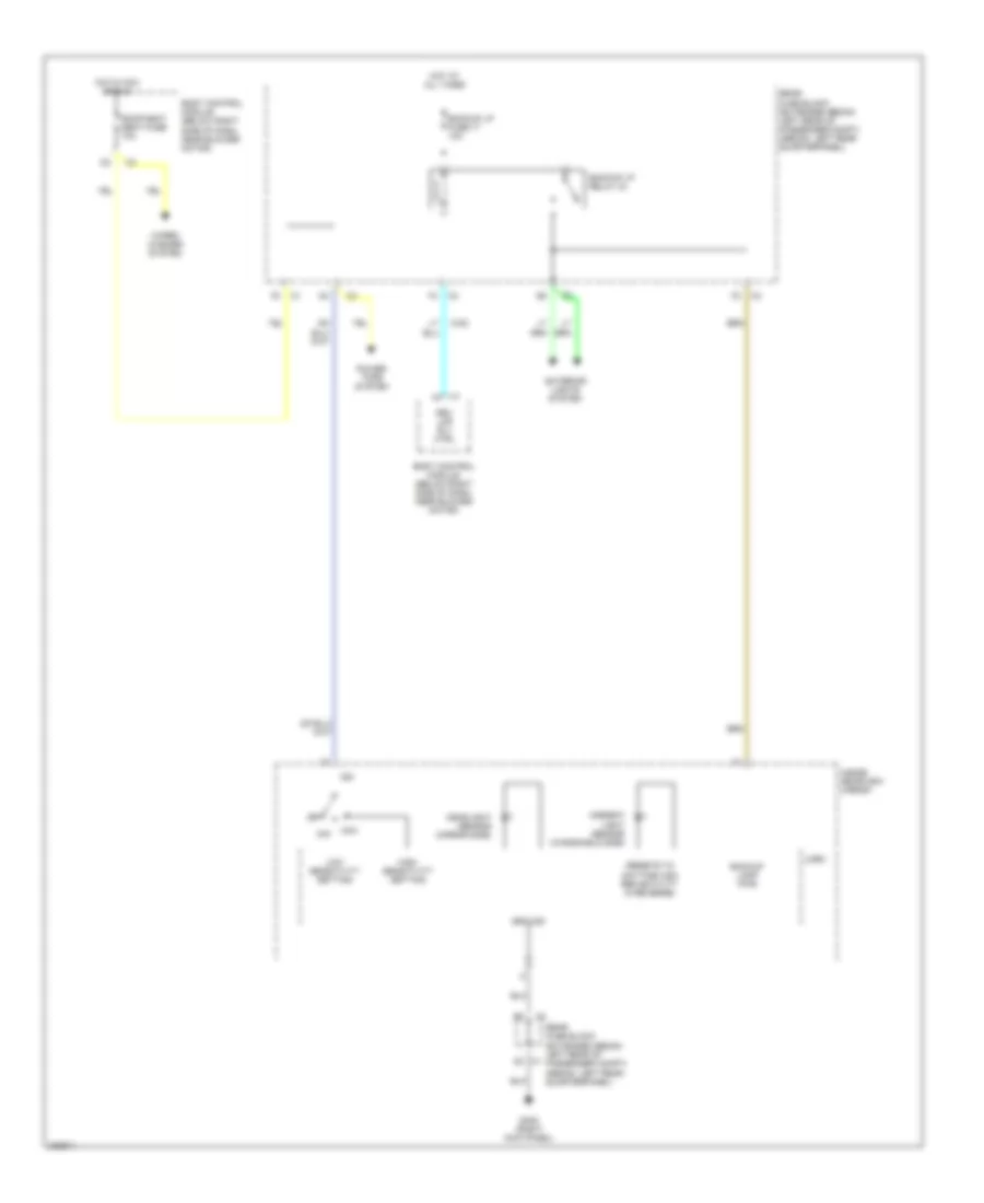
HORN
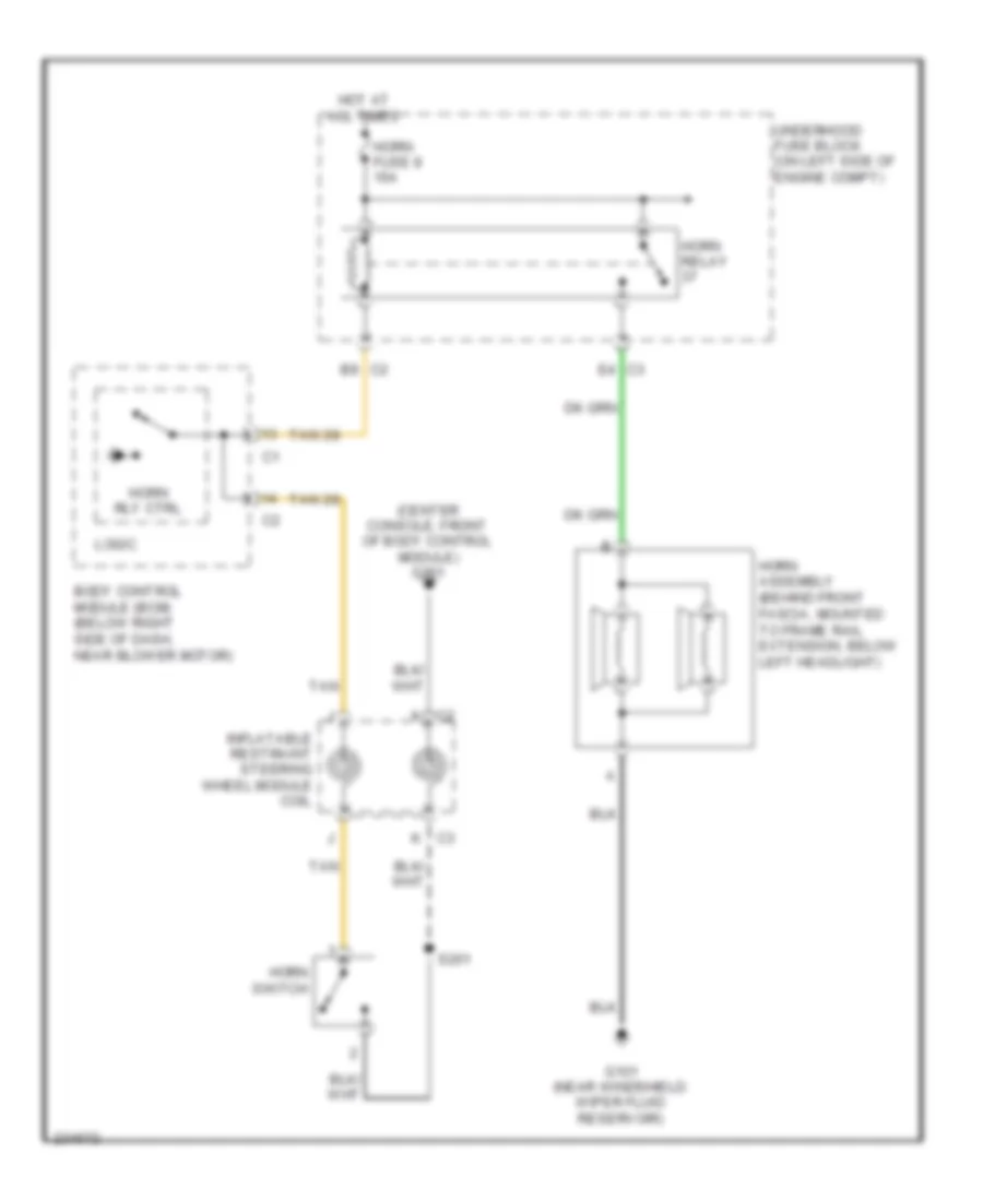
Horn Wiring Diagram for Chevrolet Malibu LT 2006
List of elements for Horn Wiring Diagram for Chevrolet Malibu LT 2006:
- (center console, front of body control module) g201
- B9 c2
- Body control module (bcm) (below right side of dash, near blower motor)
- C2 k
- C3 k
- E4 c3
- G101 (near windshield wiper fluid reservoir)
- Horn assembly (behind front fascia, mounted to frame rail extension, below left headlight)
- Horn fuse 8 15a
- Horn relay
- Horn rly ctrl
- Horn switch
- Hot at all times
- Inflatable restraint steering wheel module coil
- Logic
- S201
- Tan
- Underhood fuse block (on left side of engine compt)
INSTRUMENT CLUSTER
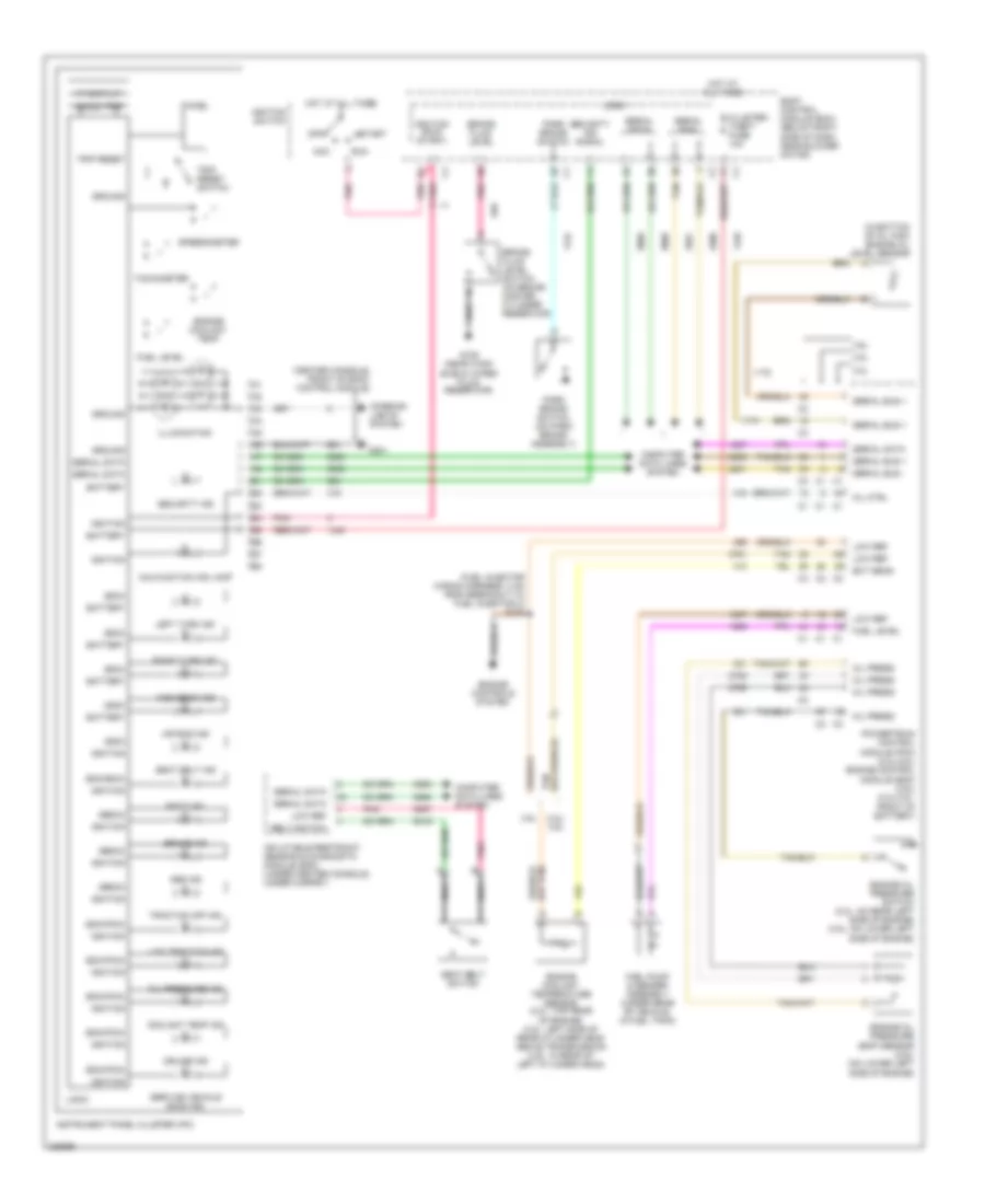
Instrument Cluster Wiring Diagram for Chevrolet Malibu LT 2006
List of elements for Instrument Cluster Wiring Diagram for Chevrolet Malibu LT 2006:
- (bcm)
- (center console, front of body control module)
- (ebcm)
- (ecm/bcm)
- (ecm/pcm)
- (fuel injector wiring harness, 3 cm from breakout to fuel injector 3) s106
- (in bottom of oil pan) engine oil level sensor
- (sdm)
- 000000 trip
- 2.2l
- 2.2l/ 3.9l
- 3.5l
- 3.9l
- Abs ind
- Acc
- Air bag ind
- Batt ind
- Battery
- Belt switch
- Body control module (bcm) (below right side of dash, near blower motor)
- Brake fluid level
- Brake fluid level switch (on brake master cylinder reservoir)
- Brake ind
- Chime
- Cluster/ theft fuse 10a
- Computer data lines system
- Coolant temp ind
- Cruise ind
- Ect sens
- Engine controls system
- Engine coolant temp
- Engine coolant temperature sensor (2.2l: top rear of engine) (3.5l: left side of rear cylinder head above transmission) (3.9l: in rear of left cylinder head)
- Engine oil pressure (eop) sensor (3.9l) (on lower left side of engine)
- Engine oil pressure switch (2.2l: on rear left side of engine) (3.5l: on lower left side of engine)
- Fuel level
- Fuel pump & sender assembly (under rear of vehicle, in fuel tank)
- G109 (near wind- shield wiper fluid reservoir)
- G201
- Ground
- High beam ind
- Hot at all times
- Ignition
- Ignition (run/ start)
- Ignition switch
- Illumination
- Inflatable restraint sensing & diagnostic module (sdm) (under center console, under carpet)
- Instrument panel cluster (ipc)
- Interior lights system
- Left turn ind
- Logic
- Low ref
- Low traction ind
- Malfunction ind lamp
- Mil ctrl
- Nca
- Off
- Oil press
- Oil pressure ind
- Park brake switch
- Park brake switch (on park brake assembly)
- Pnk
- Powertrain control module (pcm) (2.2l/3.5l) engine control module (ecm) (3.9l) (2.2l/3.5l: front of battery)
- Right turn ind
- Run
- Seat belt ind
- Seat belt switch
- Security ind
- Security ind signal
- Serial bus
- Serial bus +
- Serial bus -
- Serial data
- Service vehicle soon ind
- Speedometer
- Start
- Tachometer
- Tan
- Traction off ind
- Trip reset
- Trip reset switch
- Vf display
INTERIOR LIGHTS
Courtesy Lamps Wiring Diagram for Chevrolet Malibu LT 2006
List of elements for Courtesy Lamps Wiring Diagram for Chevrolet Malibu LT 2006:
- (if equipped)
- (not used)
- A10
- A5 c4
- Battery+
- Body control module (bcm) (below right side of dash, near blower motor)
- Cargo lamp
- Cargo lamp switch
- Courtesy v+
- Ctsy lp ctrl
- D8 c1
- D9 c1
- Dome
- Dome/ reading lamp
- Door
- Door ajar
- Driver door latch assembly ajar
- E6 c1
- Extended sedan
- F2 c4
- F5 c3
- Front courtesy/ reading lamps
- G301 (behind right rear seat back)
- G302 (behind left rear seat)
- G302 (behind rear seat, on left quarterpanel)
- G302 (extended sedan) (behind rear seat, on left quarterpanel)
- G302 (sedan) (behind left rear seat)
- Hot at all times
- Interior lights fuse 10a
- Left rear door latch ajar assembly
- Left vanity mirror lamp
- Lf door ajar
- Off
- Passenger door latch assembly ajar
- Reading
- Rear comp- artment courtesy lamp
- Rear comp- artment lid latch
- Rear fuse block (sedan: left rear quarterpanel) (extended sedan: left rear of passenger compartment)
- Rear lid ajar
- Right rear door latch ajar assembly
- Right vanity mirror lamp
- Sedan
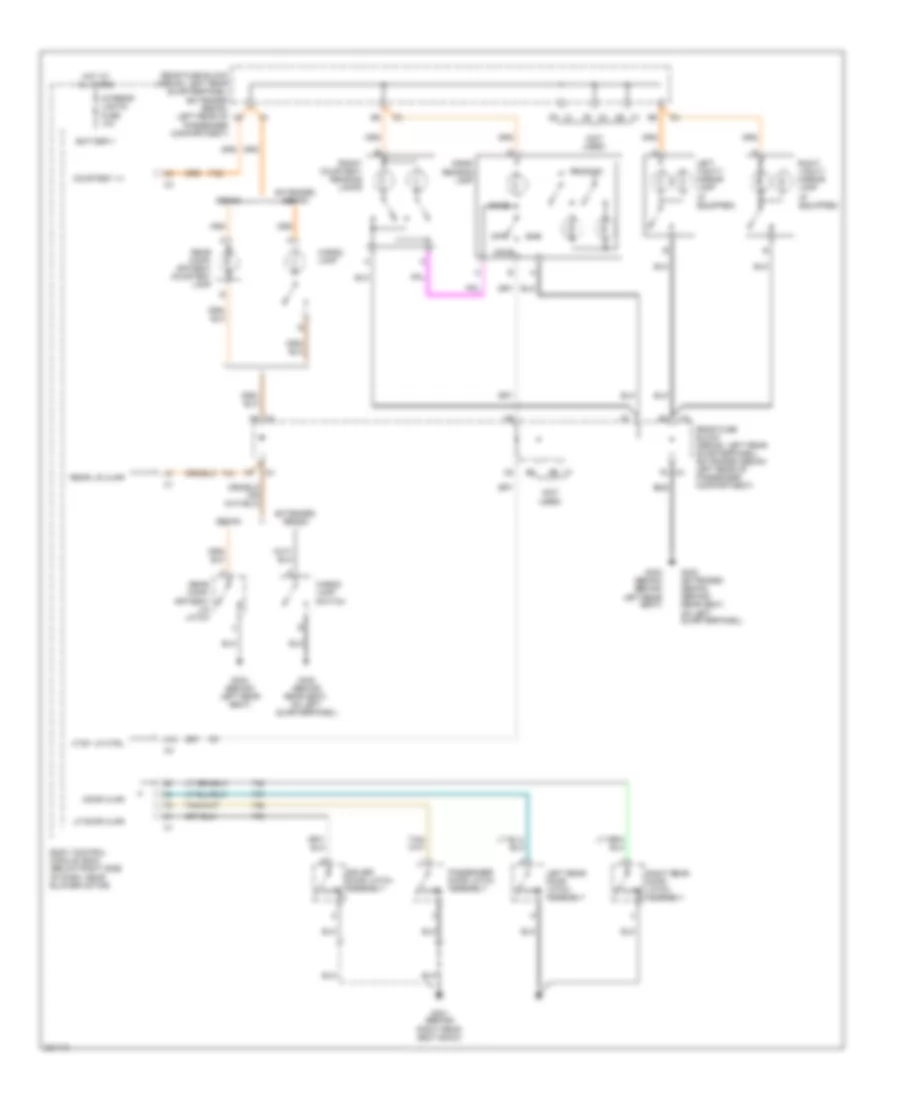
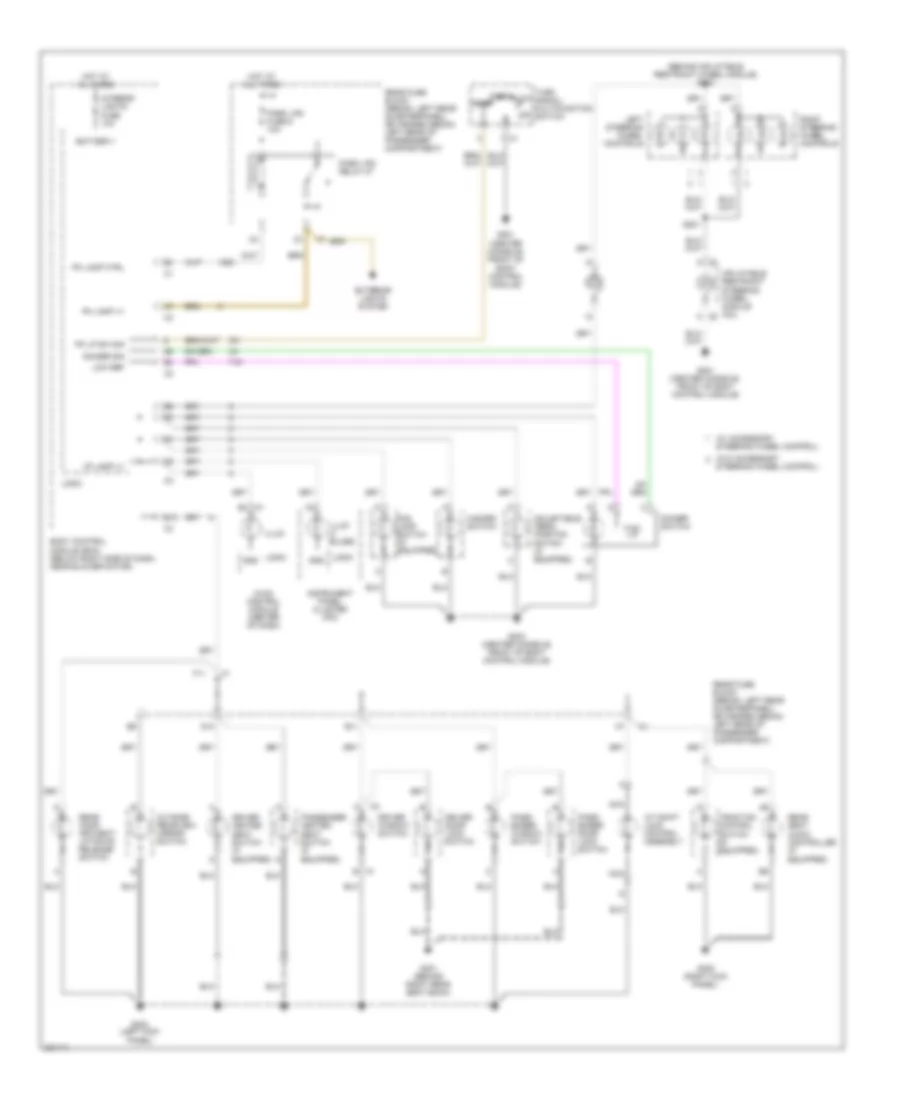
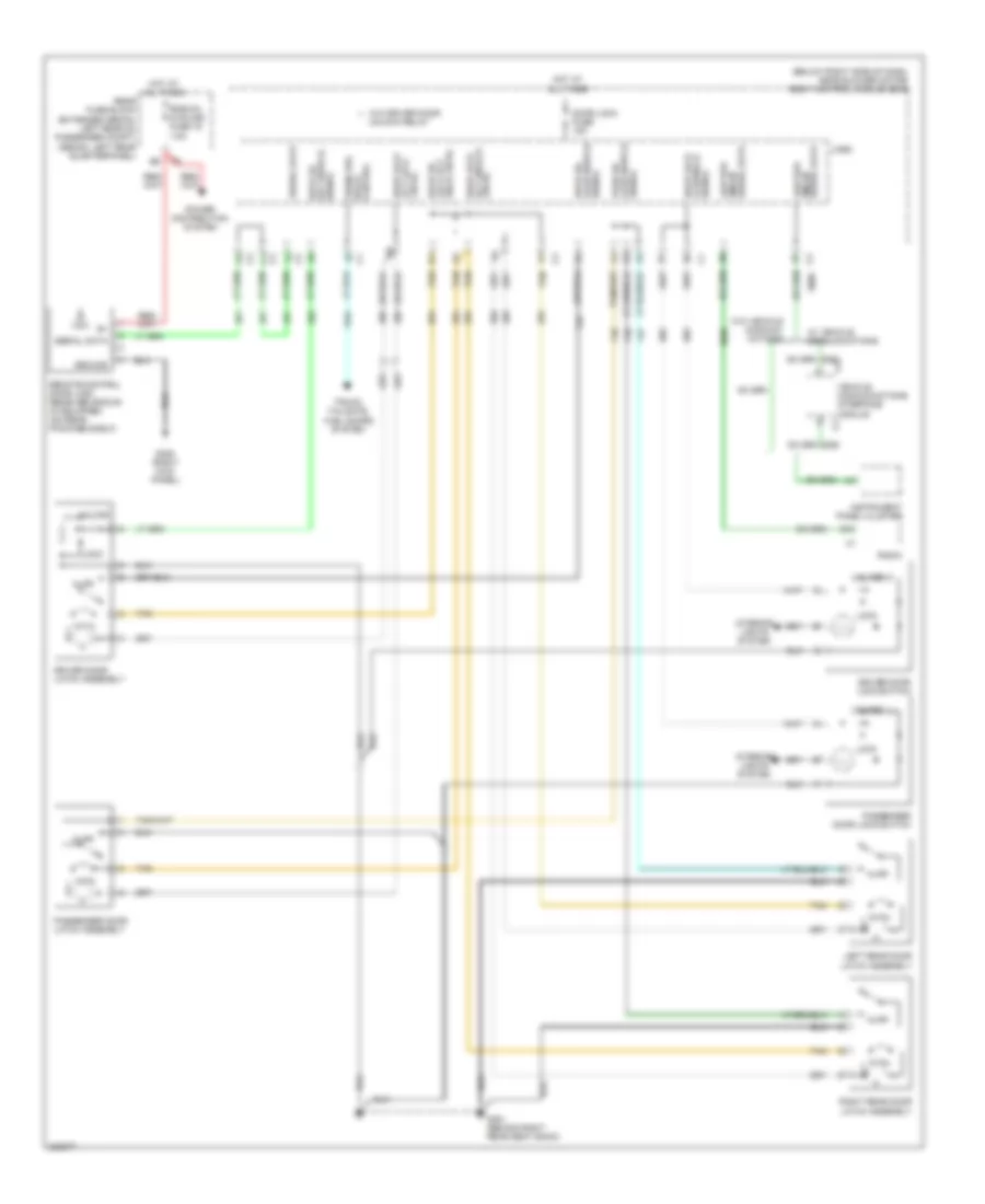
Instrument Illumination Wiring Diagram for Chevrolet Malibu LT 2006
List of elements for Instrument Illumination Wiring Diagram for Chevrolet Malibu LT 2006:
- (behind inflatable restraint wheel module) s202
- (w/ accessory
- (w/o accessory
- A/t shift lock control assembly
- Adjustable pedal position switch (if equipped)
- B12
- Battery+
- Body control module (bcm) (below right side of dash, near blower motor)
- C1 b
- C1 b3
- C3 k
- D10
- Dimmer sig
- Dimmer switch
- Driver door lock switch
- Driver heated seat switch (if equipped)
- Driver window switch
- E11
- Exterior lights system
- F11
- Fog lamp switch (if equipped)
- G201 (center console, front of body control module)
- G203 (center console, front of body control module)
- G301 (behind right rear seat back)
- G303 (left kick panel)
- G305 (right kick panel)
- Gnd
- Hazard switch
- Head
- Hot at all times
- Hvac control module (center of dash)
- I/p lamp v+
- Illum
- Illum (4 bulbs)
- Inflatable restraint steering wheel module coil
- Instrument panel cluster (ipc)
- Interior lights fuse 10a
- K c2
- Left steering wheel controls
- Logic
- Low ref
- Nca
- Off
- Outside rearview mirror switch
- Park
- Park lps fuse 6 10a
- Park lps relay 27
- Pass- enger door lock switch
- Pass- enger window switch
- Passenger heated seat switch (if equipped)
- Pk lamp ctrl
- Pk lamp v+
- Pk lp sw sig
- Rear comp- artment/ liftgate release switch
- Rear fuse block (sedan: left rear quarterpanel) (extended sedan: left rear of passenger compartment)
- Rear seat audio controller (if equipped)
- Right steering wheel controls
- S201
- Steering wheel control)
- Traction control switch (if equipped)
- Turn auto signal/ multifunction switch
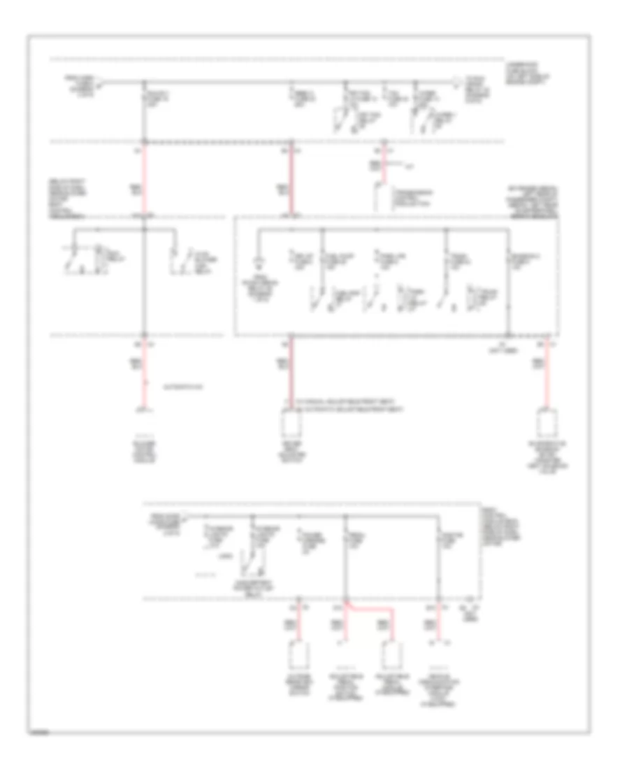
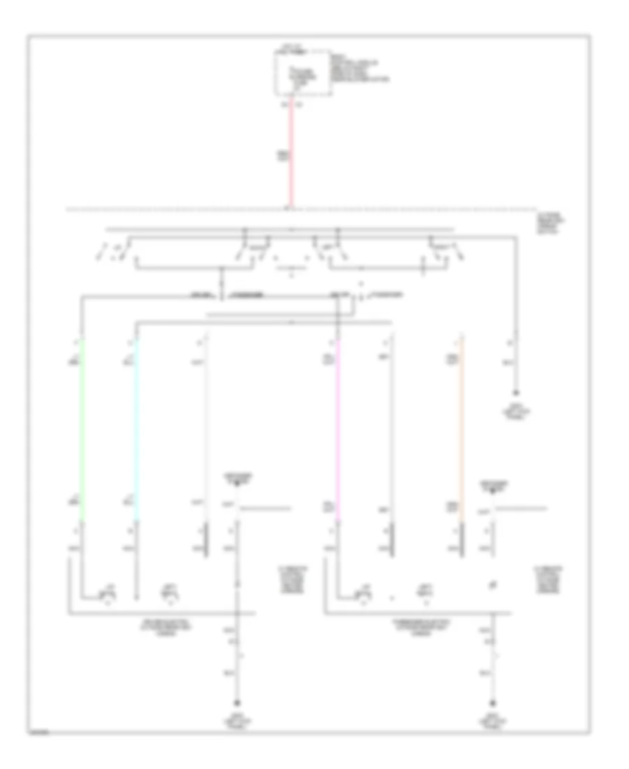
POWER DISTRIBUTION
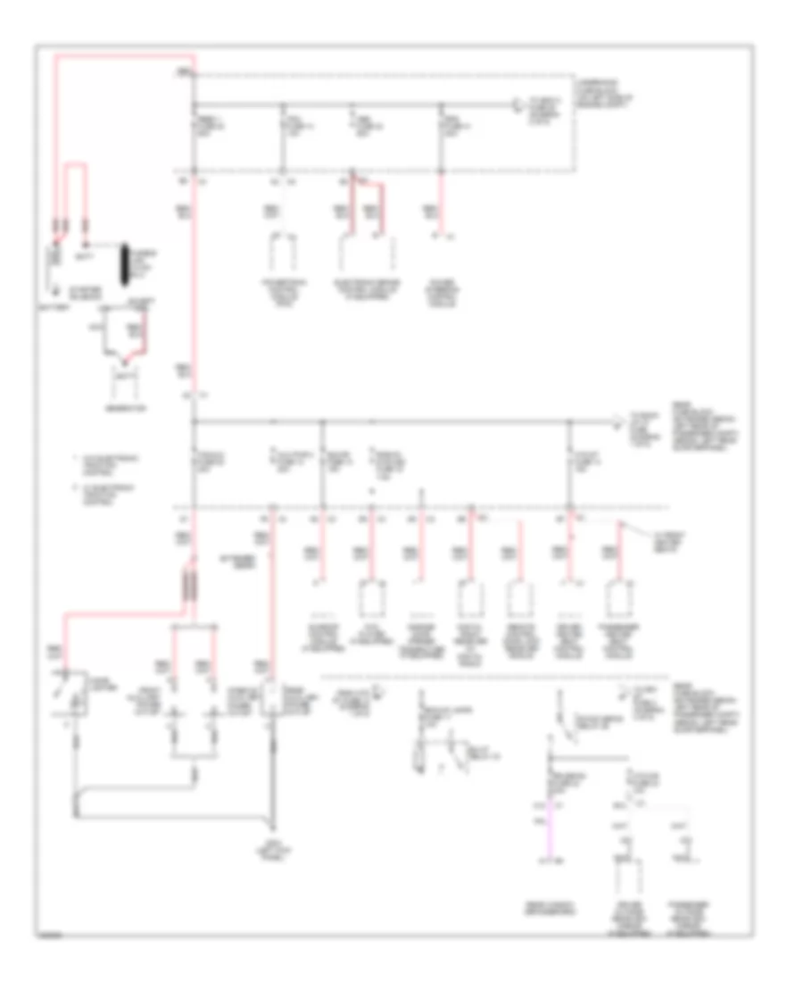
Power Distribution Wiring Diagram (1 of 5) for Chevrolet Malibu LT 2006
List of elements for Power Distribution Wiring Diagram (1 of 5) for Chevrolet Malibu LT 2006:
- 2.2l
- Abs fuse 24 60a
- Aux pwr 2 fuse 12 20a
- B12
- Batt
- Battery
- Bck/up lamps fuse 17 10a
- Bu/lp relay 33
- C12
- Cig/aux fuse 20 20a
- Cigar lighter
- Console auxiliary power outlet
- Digital radio receiver (w/ digital radio)
- Driver heated seat control module
- Driver outside rearview mirror (if equipped)
- Dvd player (if equipped)
- Electronic brake control module (if equipped)
- Eps fuse 41 80a
- Except 2.2l
- Extended sedan
- From htd b st fuse 14 (diagram 1 of 5)
- Front auxiliary power outlet
- G303 (left kick panel)
- Garage door opener transmitter (if equipped)
- Generator
- Htd mir fuse 24 10a
- Htd st fuse 14 15a
- Nca
- Passenger heated seat control module
- Passenger outside rearview mirror (if equipped)
- Pcm fuse 13 10a
- Power steering control module
- Powertrain control module (pcm)
- R/wdo defog relay 26
- Rbec 1 fuse 22 60a
- Rear auxiliary power outlet
- Rear fuse block (extended sedan: left rear of passenger compt) (sedan: left rear quarterpanel)
- Rear window defogger grid
- Red
- Remote control door lock receiver (rcdlr)
- Rke/xm dvd/ugd fuse 16 7.5a
- Rr defog fuse 23 30a
- Starter solenoid
- Sun rf fuse 10 15a
- Sunroof control module (if equipped)
- To back up lp fuse (diagram 1 of 5)
- To drv st fuse 2 (diagram 4 of 5)
- To ibcm 2 fuse 25 (diagram 2 of 5)
- Underhood fuse block (on left side of engine compt)
- W/ electronic traction control
- W/ front heated seats
- W/o electronic traction control
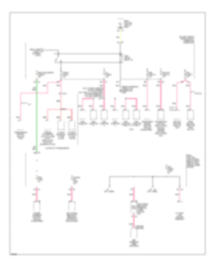
Power Distribution Wiring Diagram (2 of 5) for Chevrolet Malibu LT 2006
List of elements for Power Distribution Wiring Diagram (2 of 5) for Chevrolet Malibu LT 2006:
- (3.9l)
- (except 3.9l)
- (under left front seat) s301
- 40a
- A/c clu fuse 1 10a
- A/c clutch relay 34
- Accessory relay
- B10
- Body control module (bcm)
- Body control module (bcm) (below right side of dash, near blower motor)
- Cool fan 1 fuse 17 30a
- Cool fan 2 fuse 18 30a
- Cool/fan 1 relay 28
- Cool/fan 2 relay 30
- Cool/fan ser/par relay 29
- Door lock fuse 15a
- Driver heated seat control module
- Driver heated seat switch
- Driver window switch
- Drl fuse 46 15a
- Drl relay
- F12
- From eps a fuse 41 (diagram 1 of 5)
- Ibcm 2 fuse 25 50a
- Inside rearview mirror (w/ light sensitive mirror)
- Logic
- Passenger heated seat control module
- Passenger heated seat switch
- Passenger window switch
- Power windows fuse 30a
- Pwr/trn relay 33
- Rear fuse block (extended sedan: left rear of passenger compt) (sedan: left rear quarterpanel)
- Rear window wiper module (if equipped)
- Rear wiper fuse 20a
- Rear/ wiper washer switch (if equipped)
- Rly ctrl
- Roof/heat seat fuse 10a
- Starter fuse 26 30a
- Starter relay 31
- Sunroof control module (if equipped)
- To ibcm 1 fuse 20 (diagram 3 of 5)
- To interior lights fuse (diagram 4 of 5)
- Under- hood fuse block (on left side of engine compt)
- W/ front heated seats
- Windshield wiper/ washer switch
- Wiper sw fuse 10a
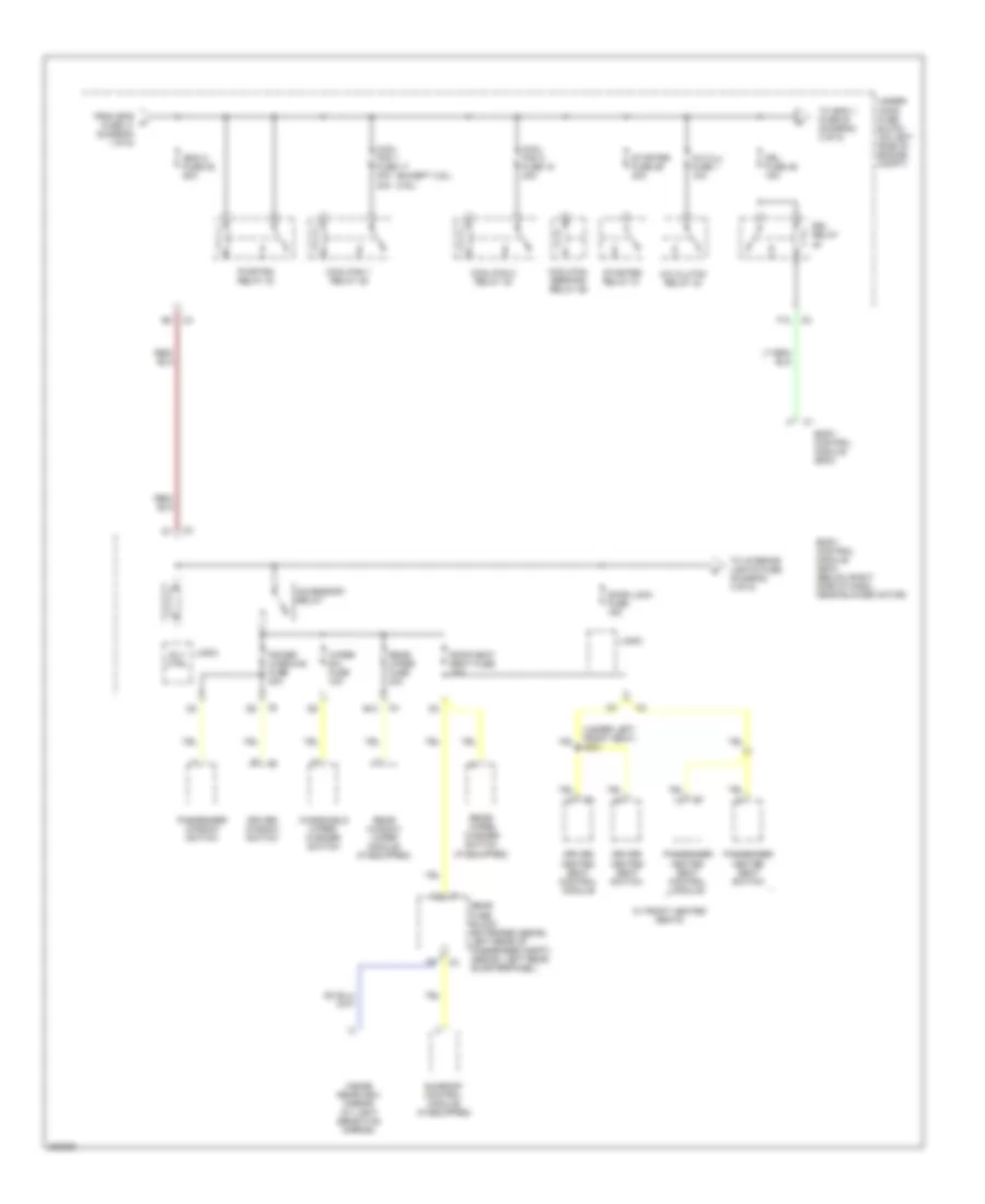
Power Distribution Wiring Diagram (3 of 5) for Chevrolet Malibu LT 2006
List of elements for Power Distribution Wiring Diagram (3 of 5) for Chevrolet Malibu LT 2006:
- (not used)
- Acc
- Acc vlt sig
- Air bag (batt) fuse 10a
- Body control module (bcm)
- Body control module (bcm) (below right side of dash, near blower motor)
- Cluster/ theft fuse 10a
- D11
- D12
- Data link connector (dlc)
- From a/c clu fuse 1 c (diagram 2 of 5)
- High beam relay 35
- Horn fuse 8 15a
- Horn relay
- Hvac control module
- Hvac ctrl (batt) fuse 10a
- Ibcm 1 fuse 20 30a
- Ign 1 vlt sig
- Ign sensor fuse 2a
- Ignition switch
- Inflatable restraint sensing & diagnostic module (sdm)
- Instrument panel cluster (ipc)
- Key in ignition switch
- Logic
- Low beam relay 38
- Off
- Off/run/crank
- Pnk
- Radio
- Radio fuse 10a
- Run
- Start
- Theft deterrent control module
- To run rly fuse 19 (diagram 4 of 5)
- Underhood fuse block (on left side of engine compt)
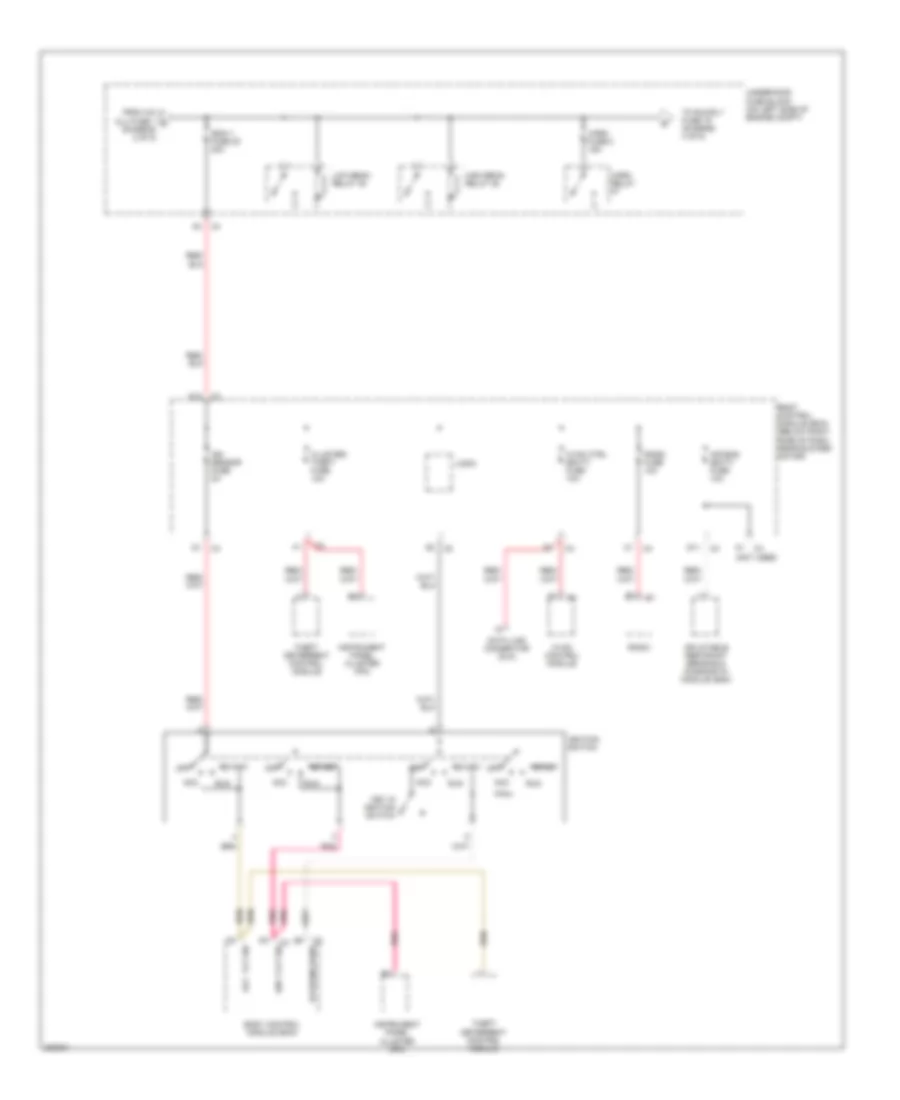
Power Distribution Wiring Diagram (4 of 5) for Chevrolet Malibu LT 2006
List of elements for Power Distribution Wiring Diagram (4 of 5) for Chevrolet Malibu LT 2006:
- (below right side of dash, near blower motor) body control module (bcm)
- (extended sedan: left rear of passenger compt) (sedan: left rear quarterpanel) rear fuse block
- (not used)
- (w/ automatic adjustable front seat)
- (w/ manual adjustable front seat)
- A/t
- Adjustable pedal module (if equipped)
- Adjustable pedal position switch (if equipped)
- Automatic a/c
- Blower motor control module
- Body control module (bcm) (below right side of dash, near blower motor)
- D10
- Driver seat adjuster switch
- Drv st fuse 2 30a
- E10
- Emission 2 fuse 5 10a
- Evaporative emission (evap) canister vent solenoid valve
- From door d locks fuse (diagram 2 of 5)
- From horn fuse 8 e (diagram 3 of 5)
- From r/wdo defog relay 26 (diagram 1 of 5)
- Frt fog lp fuse 10 10a
- Frt fog relay
- Fuel pump fuse 25 15a
- Fuel/pmp relay
- Hvac blower high relay
- Inadvertent power outlet relay
- Interior lights fuse 10a
- Logic
- Onstar fuse 10a
- Outside rearview mirror switch
- Park lp relay
- Park lps fuse 6 10a
- Pedal fuse 10a
- Power mirrors fuse 2a
- Rbec 2 fuse 23 60a
- Run relay
- Run rly fuse 19 30a
- Tcm fuse 42 10a
- To run crank relay 32 (diagram 5 of 5)
- Transmission control module (tcm)
- Trunk fuse 22 10a
- Trunk relay
- Underhood fuse block (on left side of engine compt)
- Vehicle communication interface module (vcim) (if equipped)
- Wiper 1 relay
- Wiper fuse 14 25a
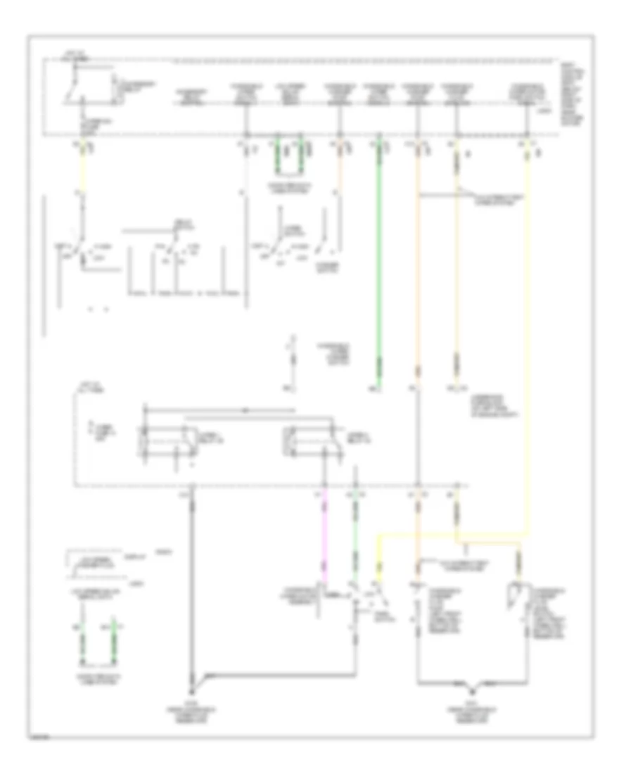
Power Distribution Wiring Diagram (5 of 5) for Chevrolet Malibu LT 2006
List of elements for Power Distribution Wiring Diagram (5 of 5) for Chevrolet Malibu LT 2006:
- (2.2l)
- (2.2l: in fuel injector wiring harness) (3.5l: fuel inj wiring harn, 4 cm from breakout to fuel injector 2)
- (3-spoke) (4-spoke)
- (3.5l)
- (if equipped)
- (near windshield wiper fluid reservoir) g109
- (not used)
- (on left side of engine compt) underhood fuse block
- 1-2 shift solenoid (1-2 ss) valve
- 2-3 shift solenoid (2-3 ss) valve
- 3.5l/2.2l
- A/t
- A/t shift lock control assembly
- A2 c4
- Abs fuse 15 10a
- Air bag ign fuse 10a
- Automatic transmission
- B10
- Body control module (bcm)
- Body control module (bcm) (below right side of dash, near blower motor)
- C10
- C2 f6
- E c100
- E c2
- Electronic brake control module
- Eps fuse 2a
- From wiper fuse 14 (diagram 4 of 5)
- Fuel injector
- Ibcm (run/crank) fuse 21 30a
- Ign 1 fuse 3 15a
- Ignition control module (icm)
- Inflatable restraint sensing & diagnostic module (sdm)
- Inflatable restraint steering wheel module coil
- Inj fuse 5 10a
- Left steering wheel controls
- Park/ neutral position (pnp) switch
- Pcm ign 1 fuse 16 10a
- Pnk
- Power steering control module (if equipped)
- Powertrain control module (pcm) (3.5l/2.2l) engine control module (ecm) (3.9l)
- Red
- Rly hi ctrl
- Run crank fuse 2a
- Run/ crank relay 32
- S103
- S130
- Torque converter clutch pulse width modulation (tcc pwm) solenoid valve
- Trans fuse 4 10a
- Transmission control module (tcm)
POWER DOOR LOCKS
Power Door Locks Wiring Diagram for Chevrolet Malibu LT 2006
List of elements for Power Door Locks Wiring Diagram for Chevrolet Malibu LT 2006:
- (below right side of dash, near blower motor) body control module (bcm)
- Ajar
- Ajar switch pass dr
- B10
- C4 c3
- Cntrl act unlock door lock
- Door lock
- Door lock act lock cntrl
- Door lock fuse 15a
- Driver door latch assembly
- Driver door lock switch
- Drvr dr ajar switch signal
- G301 (behind right rear seat back)
- G305 (right kick panel)
- Ground
- Hot at all times
- Instrument panel cluster
- Interior lights system
- Left rear door latch assembly
- Lock
- Logic
- Low spd gmlan
- Passenger door latch assembly
- Passenger door lock switch
- Power distribution system
- Radio
- Rear fuse block (extended sedan: left rear of passenger compt) (sedan: left rear quarterpanel)
- Remote control door lock receiver (rcdlr) (if equipped) (on rear package shelf)
- Right rear door latch assembly
- Rke/xm/ dvd/ugd fuse 16 7.5a
- Serial data
- Serial data gmlan low spd
- Signal
- Signal key switch drvr dr
- Signal lck/unlck
- Tan
- Trunk rel relay control
- Trunk, tailgate, fuel doors system
- Unlk cntrl lock act drvr dr
- Unlock
- Unlock relay
- Vehicle communications interface module
- W/ vehicle communications
- W/o driver door
- W/o vehicle communi- cations
POWER MIRRORS
Automatic Day/Night Mirror Wiring Diagram for Chevrolet Malibu LT 2006
List of elements for Automatic Day/Night Mirror Wiring Diagram for Chevrolet Malibu LT 2006:
- (resets to daytime high reflectivity in reverse)
- Ambient light sensor (windshield side)
- Backup lamp pwr
- Backup lp fuse 17 10a
- Backup lp relay 33
- Body control module (below right side of dash, near blower motor)
- Exterior lights system
- G305 (right kick panel)
- Ground
- Headlight sensor (mirror side)
- High sensitivity setting
- Hot at all times
- Hot in acc or run
- Ign
- Inside rearview mirror
- Logic
- Low sensitivity setting
- Max
- Min
- Off
- Power tops system
- Rear fuse block (extended sedan: left rear of passenger compt) (sedan: left rear quarterpanel)
- Rev lmp rly ctrl
- Roof/heat seat fuse 10a
- Wiper/ washer system
Power Mirrors Wiring Diagram for Chevrolet Malibu LT 2006
List of elements for Power Mirrors Wiring Diagram for Chevrolet Malibu LT 2006:
- Body control module (below right side of dash, near blower motor)
- Defogger system
- Down
- Driver
- Driver electric outside rearview mirror
- G303 (left kick panel)
- Hot at all times
- Left
- Left/ right
- Nca
- Outside rearview mirror switch
- Passenger
- Passenger electric outside rearview mirror
- Power mirrors fuse 2a
- Right
- Up/ down
- W/ remote control outside heated mirrors
POWER SEATS
2-Way Adjustable Power Seat Wiring Diagram for Chevrolet Malibu LT 2006
List of elements for 2-Way Adjustable Power Seat Wiring Diagram for Chevrolet Malibu LT 2006:
- (left kick panel)
- Down
- Driver seat adjuster switch (2-way)
- Drv st fuse 2 30a
- G303
- Hot at all times
- Rear fuse block (extended sedan: left rear of passenger compt) (sedan: left rear quarterpanel)
- Seat vertical motor (under driver's seat, on frame)
6-Way Power Seat Wiring Diagram for Chevrolet Malibu LT 2006
List of elements for 6-Way Power Seat Wiring Diagram for Chevrolet Malibu LT 2006:
- Driver seat adjuster switch (6-way)
- Drv st fuse 2 30a
- Front down
- Front up
- Fwd
- G303 (left kick panel)
- Hot at all times
- Rear down
- Rear fuse block (extended sedan: left rear of passenger compt) (sedan: left rear quarterpanel)
- Rear up
- Rwd
- Seat front vertical motor (under driver's seat, on frame)
- Seat horizontal motor (under driver's seat, on frame)
- Seat rear vertical motor (under driver's seat, on frame)
- Tan
Adjustable Pedal Wiring Diagram for Chevrolet Malibu LT 2006
List of elements for Adjustable Pedal Wiring Diagram for Chevrolet Malibu LT 2006:
- Adj pedal inhibit sw
- Adjustable pedals actuator
- Adjustable pedals module
- Adjustable pedals position sensor (left of steering wheel)
- Adjustable pedals position switch
- Battery
- Body control module (below right side of dash, near blower motor)
- D10
- Enable sig
- Fwd
- G201 (center console, front of body control module)
- Gnd
- Hot at all times
- Inhibit sig
- Logic
- Low ref
- Pedal fuse 10a
- Pnk
- Rwd
- Sens sig
Heated Seats Wiring Diagram for Chevrolet Malibu LT 2006
List of elements for Heated Seats Wiring Diagram for Chevrolet Malibu LT 2006:
- (left kick panel) g303
- Accy vlt
- Accy voltage
- Battery
- Body control module (bcm) (below right side of dash, near blower motor)
- Driver heated seat back element
- Driver heated seat control module
- Driver heated seat cushion element
- Driver heated seat cushion temperature sensor
- Driver heated seat switch
- Front passenger heated seat back element
- Front passenger heated seat cushion element
- G303 (left kick panel)
- Ground
- Heated seat sw sig
- High
- Hot at all times
- Hot in run or acc
- Htd seat fuse 14 15a
- Illum
- Interior lights system
- Logic
- Low
- Off
- Passenger heated seat control module
- Passenger heated seat cushion temperature sensor
- Passenger heated seat switch
- Rear fuse block (extended sedan: left rear of passenger compt) (sedan: left rear quarterpanel)
- Red
- Roof/ heat seat fuse 10a
- S301
- Seat back element ctrl
- Seat back element voltage
- Seat cushion element ctrl
- Seat cushion element voltage
- Seat cushion temp sen low ref
- Seat cushion temp sen sig
POWER TOP/SUNROOF
Power Top/Sunroof Wiring Diagram for Chevrolet Malibu LT 2006
List of elements for Power Top/Sunroof Wiring Diagram for Chevrolet Malibu LT 2006:
- Accessory voltage
- Battery positive voltage
- Body control module (bcm) (below right side of dash, near blower motor)
- C4 f2
- Close
- G302 (sedan: behind left rear seat) (extended sedan: behind rear seat, on left quarterpanel)
- Ground
- Hot at all times
- Hot in acc or run
- Open
- Power distribution system
- Rear fuse block (sedan: left rear quarterpanel) (extended sedan: left rear of passenger compt)
- Roof/heat seat fuse 10a
- S/roof fuse 10 15a
- Sunroof control module (rear of sunroof)
- Sunroof switch
- Sunroof switch close signal
- Sunroof switch low reference
- Sunroof switch open signal
- Wiper/ washer system
POWER WINDOWS
Power Windows Wiring Diagram for Chevrolet Malibu LT 2006
List of elements for Power Windows Wiring Diagram for Chevrolet Malibu LT 2006:
- (left kick panel)
- A11
- B11
- Body control module (bcm) (below right side of dash, near blower motor)
- C11
- C3 d5
- Down
- Driver
- Driver window motor
- Driver window switch
- Ecb
- Express down
- Express logic
- G303
- Ground distribution system
- Hot w/ accessory relay energized
- Illumination lamp
- Interior lights system
- Left rear
- Left rear window motor (left rear door)
- Left rear window switch
- Lock out switch
- Passenger
- Passenger window motor
- Passenger window switch
- Power windows fuse 30a
- Right rear
- Right rear window motor
- Right rear window switch
- Tan
RADIO
4-Speaker System Wiring Diagram for Chevrolet Malibu LT 2006
List of elements for 4-Speaker System Wiring Diagram for Chevrolet Malibu LT 2006:
- 10 volt ref
- A10
- A11
- A12
- Antenna amplifier module (sedan: rear center of roof, under headliner)
- B10
- B11
- B12
- Bare
- Battery
- Body control module (bcm) (below right side of dash, near blower motor)
- Cell phone low ref
- Cell phone voice sig
- Computer data lines system
- Drain wire
- G201 (center console, front of body control module)
- Gmlan ser data
- Ground
- Hot at all times
- Inflatable restraint steering wheel module coil
- Left front door speaker
- Left rear speaker
- Lf speaker (+)
- Lf speaker (-)
- Logic
- Lr speaker (+)
- Lr speaker (-)
- Nca
- Pnk
- Radio
- Radio antenna
- Radio fuse 10a
- Rear window antenna module
- Rf speaker (+)
- Rf speaker (-)
- Right front door speaker
- Right rear speaker
- Right steering wheel controls
- Rr speaker (+)
- Rr speaker (-)
- Strng whl ctrl sig
- Tan
- Vehicle communication interface module (w/ on star)
6-Speaker System Wiring Diagram, with DVD (1 of 2) for Chevrolet Malibu LT 2006
List of elements for 6-Speaker System Wiring Diagram, with DVD (1 of 2) for Chevrolet Malibu LT 2006:
- (extended sedan: right side of rear compt, behind wheelwell) (sedan: right rear side of rear compt)
- (right kick panel) g305
- 10 volt ref
- A10
- A11
- A12
- Audio common
- B10
- B11
- B12
- Bare
- Battery
- Body control module (bcm) (below right side of dash, near blower motor)
- Cell phone low ref
- Cell phone voice sig
- Coax
- Computer data lines system
- Digital radio antenna
- Digital radio receiver (w/ digital audio system)
- Drain wire
- G201 (center console, front of body control module)
- Gmlan ser data
- Ground
- Hot at all times
- Inflatable restraint steering wheel module coil
- Lf speaker (+)
- Lf speaker (-)
- Lr speaker (+)
- Lr speaker (-)
- Lt audio sig (+)
- Radio
- Radio antenna
- Radio fuse 10a
- Rear fuse block (extended sedan: left rear of passenger compt) (sedan: left rear quarterpanel)
- Rf speaker (+)
- Rf speaker (-)
- Right steering wheel controls
- Rke/xm dvd/ugd fuse 16 7.5a
- Rr speaker (+)
- Rr speaker (-)
- Rt audio sig (+)
- Strng whl ctrls sig
- Tan
- Vehicle communication interface module (w/ on star)
6-Speaker System Wiring Diagram, with DVD (2 of 2) for Chevrolet Malibu LT 2006
List of elements for 6-Speaker System Wiring Diagram, with DVD (2 of 2) for Chevrolet Malibu LT 2006:
- (right kick panel) g305
- Audio common
- Bare
- Battery
- Braided ground strap
- Bright ctrl
- Computer data lines system
- Drain wire
- Dvd player
- Gmlan ser data
- Ground
- Left front door speaker
- Left front door tweeter speaker
- Left rear door speaker
- Lr speaker (+)
- Lr speaker (-)
- Lt audio sig (-)
- Nca
- Red
- Right front door speaker
- Right front door tweeter speaker
- Right rear door speaker
- Rr speaker (+)
- Rr speaker (-)
- Rt audio sig (+)
- Select 1
- Select 2
- Tan
- Tan b
- Video 8v
- Video ground
- Video screen
- Video signal
6-Speaker System Wiring Diagram, with Rear Controls (1 of 2) for Chevrolet Malibu LT 2006
List of elements for 6-Speaker System Wiring Diagram, with Rear Controls (1 of 2) for Chevrolet Malibu LT 2006:
- (extended sedan: right side of rear compt, behind wheelwell) (sedan: right rear side of rear compt)
- (right kick panel) g305
- 10 volt ref
- A10
- A11
- A12
- Antenna signal
- Audio common
- B10
- B11
- B12
- Bare
- Battery
- Body control module (bcm) (below right side of dash, near blower motor)
- Cell phone low ref
- Cell phone voice sig
- Coax
- Computer data lines system
- Digital radio antenna
- Digital radio receiver (w/ digital audio system)
- Drain wire
- Dvd circuit
- G201 (center console, front of body control module)
- Gmlan ser data
- Ground
- Hot at all times
- Lf speaker (+)
- Lf speaker (-)
- Lr speaker (+)
- Lr speaker (-)
- Lt audio sig (+)
- Power distribution system
- Radio
- Radio antenna
- Radio fuse 10a
- Rear fuse block (extended sedan: left rear of passenger compt) (sedan: left rear quarterpanel)
- Rem radio ctrl sig
- Rf speaker (+)
- Rf speaker (-)
- Rke/xm dvd/ugd fuse 16 7.5a
- Rr speaker (+)
- Rr speaker (-)
- Rsa enable sig
- Rt audio sig (+)
- Strng whl ctrl sig
- Tan
- Vehicle communication interface module (w/ onstar)
6-Speaker System Wiring Diagram, with Rear Controls (2 of 2) for Chevrolet Malibu LT 2006
List of elements for 6-Speaker System Wiring Diagram, with Rear Controls (2 of 2) for Chevrolet Malibu LT 2006:
- 10 volt ref
- B tan
- Exterior lights system
- G305 (right kick panel)
- Ground
- I/p lamp volt
- Inflatable restraint steering wheel module coil
- Interior lights system
- Left front door speaker
- Left front door tweeter speaker
- Left rear door speaker
- Lr speaker (+)
- Lr speaker (-)
- Nca
- Prk lmps voltage
- Rear seat audio controller
- Rem radio ctrl sig
- Right front door speaker
- Right front door tweeter speaker
- Right rear door speaker
- Right steering wheel controls
- Rr speaker (+)
- Rr speaker (-)
- Rsa enable sig
- Tan
6-Speaker System Wiring Diagram, without DVD or Rear Controls (1 of 2) for Chevrolet Malibu LT 2006
List of elements for 6-Speaker System Wiring Diagram, without DVD or Rear Controls (1 of 2) for Chevrolet Malibu LT 2006:
- (extended sedan: right side of rear compt, behind wheelwell) (sedan: right rear side of rear compt)
- (right kick panel) g305
- 10 volt ref
- A10
- A11
- A12
- Antenna amplifier module (sedan: rear center of roof, under headliner)
- Antenna signal
- Audio common
- B10
- B11
- B12
- Bare
- Battery
- Body control module (bcm) (below right side of dash, near blower motor)
- Cell phone low ref
- Cell phone voice sig
- Coax
- Computer data lines system
- Digital radio antenna
- Digital radio receiver (w/ digital audio system)
- Drain wire
- Extended sedan
- G201 (center console, front of body control module)
- Gmlan ser data
- Ground
- Hot at all times
- Lf speaker (+)
- Lf speaker (-)
- Logic
- Lr speaker (+)
- Lr speaker (-)
- Lt audio sig (+)
- Pnk
- Power distribution system
- Radio
- Radio antenna
- Radio fuse 10a
- Rear fuse block (extended sedan: left rear of passenger compt) (sedan: left rear quarterpanel)
- Rear window antenna module
- Rf speaker (+)
- Rf speaker (-)
- Rke/xm dvd/ugd fuse 16 7.5a
- Rr speaker (+)
- Rr speaker (-)
- Rt audio sig (+)
- Sedan
- Strng whl ctrl sig
- Tan
- Vehicle communication interface module (w/ onstar)
6-Speaker System Wiring Diagram, without DVD or Rear Controls (2 of 2) for Chevrolet Malibu LT 2006
List of elements for 6-Speaker System Wiring Diagram, without DVD or Rear Controls (2 of 2) for Chevrolet Malibu LT 2006:
- B tan
- Inflatable restraint steering wheel module coil
- Left front door speaker
- Left front door tweeter speaker
- Left rear speaker (sedan) left rear door speaker (extended sedan)
- Nca
- Right front door speaker
- Right front door tweeter speaker
- Right rear speaker (sedan) right rear door speaker (extended sedan)
- Right steering wheel controls
- Tan
SHIFT INTERLOCK
Shift Interlock Wiring Diagram for Chevrolet Malibu LT 2006
List of elements for Shift Interlock Wiring Diagram for Chevrolet Malibu LT 2006:
- 5 volt reference
- A/t shift lock control assembly
- A/t shift lock control solenoid
- Battery
- Body control module (bcm) (below right side of dash, near blower motor)
- Brake pedal position sensor (on brake pedal support)
- Brake pedal position sensor signal
- Door lock fuse 15a
- G303 (left kick panel)
- G305 (right kick panel)
- Ground
- Hot at all times
- Interior lights fuse 10a
- Logic
- Low reference
STARTING/CHARGING
Charging Wiring Diagram for Chevrolet Malibu LT 2006
List of elements for Charging Wiring Diagram for Chevrolet Malibu LT 2006:
- (2.2l & 3.9l)
- (ecm/ pcm)
- 2.2l
- 3.5l & 3.9l
- 3.5l 2.2l
- 3.9l
- Battery
- Charge indicator
- Class 2 serial data
- Computer data lines system
- G104 (left side of engine compt)
- G105 (3.5l: right rear of engine, on engine to transmission stud)
- Generator
- Generator field duty cycle signal
- Generator turn on signal
- High speed gmlan serial data bus +
- High speed gmlan serial data bus -
- Ign
- Instrument panel cluster (ipc)
- Low speed gmlan serial data
- Power distribution system
- Powertrain control module (pcm) (3.5l & 2.2l) engine control module (ecm) (3.9l) (3.5l & 2.2l: front of battery)
- Red
- Starter solenoid
- Tan
2.2L VIN F
2.2L VIN F, Starting Wiring Diagram for Chevrolet Malibu LT 2006
List of elements for 2.2L VIN F, Starting Wiring Diagram for Chevrolet Malibu LT 2006:
- (2.2l)
- (below right side of dash, near blower motor) body control module (bcm)
- (on left side of engine compt) underhood fuse block
- 2.2l
- 3.5l
- 5v ref
- A3 c2
- Acc
- B10
- Battery
- C1 c2
- C10
- C4 d1
- Charging circuit
- Computer data lines system
- D10 c1
- D12 c1
- Door lock lock/unlock signal
- Door locks system
- E11
- Ecm high speed gmlan serial data bus +
- Ecm high speed gmlan serial data bus -
- Exterior lights system
- G101 (near windshield wiper fluid reservoir)
- G104 (left side of engine compt)
- G105 (3.5l: right rear of engine, on engine to transmission stud)
- G109 (near windshield wiper fluid reservoir)
- Hazard switch signal
- High speed gmlan serial data bus +
- High speed gmlan serial data bus -
- Hood ajar switch
- Hood ajar switch signal
- Hot at all times
- Ign 1 fuse 3 15a
- Ign 1 vol
- Ignition sensor fuse 2a
- Ignition switch
- Key-in ignition switch
- Logic
- Nca
- Off
- Off/run crank voltage signal
- Park/neutral position (pnp) switch (3.5l: on top of transmission)
- Pnk
- Pnp sw input
- Power distribution system
- Powertrain control module (pcm) (front of battery)
- Red
- Run
- Run/crank relay 32
- Run/crank relay coil control
- Serial data
- Start
- Starter fuse 26 30a
- Starter relay 31
- Starter rly coil ctrl
- Starter solenoid
- Tan
- Underhood fuse block (on left side of engine compt)
- W/ remote keyless entry
3.5L VIN 8
3.5L VIN 8, Starting Wiring Diagram for Chevrolet Malibu LT 2006
List of elements for 3.5L VIN 8, Starting Wiring Diagram for Chevrolet Malibu LT 2006:
- (2.2l)
- (below right side of dash, near blower motor) body control module (bcm)
- (on left side of engine compt) underhood fuse block
- 2.2l
- 3.5l
- 5v ref
- A3 c2
- Acc
- B10
- Battery
- C1 c2
- C10
- C4 d1
- Charging circuit
- Computer data lines system
- D10 c1
- D12 c1
- Door lock lock/unlock signal
- Door locks system
- E11
- Ecm high speed gmlan serial data bus +
- Ecm high speed gmlan serial data bus -
- Exterior lights system
- G101 (near windshield wiper fluid reservoir)
- G104 (left side of engine compt)
- G105 (3.5l: right rear of engine, on engine to transmission stud)
- G109 (near windshield wiper fluid reservoir)
- Hazard switch signal
- High speed gmlan serial data bus +
- High speed gmlan serial data bus -
- Hood ajar switch
- Hood ajar switch signal
- Hot at all times
- Ign 1 fuse 3 15a
- Ign 1 vol
- Ignition sensor fuse 2a
- Ignition switch
- Key-in ignition switch
- Logic
- Nca
- Off
- Off/run crank voltage signal
- Park/neutral position (pnp) switch (3.5l: on top of transmission)
- Pnk
- Pnp sw input
- Power distribution system
- Powertrain control module (pcm) (front of battery)
- Red
- Run
- Run/crank relay 32
- Run/crank relay coil control
- Serial data
- Start
- Starter fuse 26 30a
- Starter relay 31
- Starter rly coil ctrl
- Starter solenoid
- Tan
- Underhood fuse block (on left side of engine compt)
- W/ remote keyless entry
3.9L VIN 1
3.9L VIN 1, Starting Wiring Diagram for Chevrolet Malibu LT 2006
List of elements for 3.9L VIN 1, Starting Wiring Diagram for Chevrolet Malibu LT 2006:
- (in left side of engine compt)
- (on left rear side of core support, between windshield washer fluid reservoir & g109) g101
- (under front of center console)
- Acc
- B10
- Battery
- C1 c2
- C10
- Charging circuit
- Computer data lines system
- D1 c4
- D12 c1
- Door lock lock/unlock signal
- Door locks system
- E11
- Engine control module (ecm) (left side of engine compt, in front of battery)
- Exterior lights system
- G104 (on left side of engine compt, on core support, between left inflatable restraint front end sensor & g109)
- G105 (on left rear side of engine compt, on engine transmission stud, below upper coolant hose)
- G109 (left front of engine compt, on left rear side of core support, between g101 & g104)
- Hazard switch signal
- High speed gmlan serial data bus +
- High speed gmlan serial data bus -
- Hood ajar switch (w/ rke) (in front of engine compt, on hood latch)
- Hood ajar switch signal
- Hot at all times
- Ign 1
- Ign sensor fuse 2a
- Ignition 1
- Ignition switch
- Key in ignition switch
- Logic
- Nca
- Off
- Off/run crank voltage 5v ref
- Pcm ign 1 fuse 16 10a
- Pnk
- Power distribution system
- Red
- Run
- Run/crank relay 32
- Run/crank relay coil control
- Serial data
- Start
- Start relay 31
- Starter rly coil ctrl
- Starter solenoid
- Strtr fuse 26 30a
- Tan
- Underhood fuse block
- Underhood fuse block (in left side of engine compt)
SUPPLEMENTAL RESTRAINTS
Supplemental Restraints Wiring Diagram (1 of 2) for Chevrolet Malibu LT 2006
List of elements for Supplemental Restraints Wiring Diagram (1 of 2) for Chevrolet Malibu LT 2006:
- A pnk
- Air bag (batt) fuse 10a
- Air bag (ign) fuse 10a
- Body control module (bcm) (below right side of dash, near blower motor)
- Case ground
- Computer data lines system
- D11
- G304 (right kick panel)
- Ground
- High control
- Hot at all times
- Hot in run or start
- Ignition 1
- Inflatable restraint sensing & diagnostic module (sdm) (under center console, under carpet)
- Left front inflatable restraint seat belt pretensioner (bottom of left "b" pillar)
- Left inflatable restraint front end sensor (left front of engine compt)
- Left inflatable restraint roof rail module (on upper left "c" pillar)
- Left inflatable restraint side impact sensor (sis) (behind door panel)
- Low control
- Low ref
- Nca
- Pnk
- Right front inflatable restraint seat belt pretensioner (bottom of right "b" pillar)
- Right inflatable restraint front end sensor (right front of engine compt)
- Right inflatable restraint roof rail module (on upper right "c" pillar)
- Right inflatable restraint side impact sensor (sis) (behind door panel)
- Seat belt switch
- Serial data
- Shorting bar
- Signal
- Tan
- Voltage
Supplemental Restraints Wiring Diagram (2 of 2) for Chevrolet Malibu LT 2006
List of elements for Supplemental Restraints Wiring Diagram (2 of 2) for Chevrolet Malibu LT 2006:
- A c1
- Air bag indicator
- B c2
- Batt
- Body control module (bcm) (below right side of dash, near blower motor)
- Computer data lines system
- Inflatable restraint i/p module (above glove box)
- Inflatable restraint steering wheel module (under horn pad)
- Inflatable restraint steering wheel module coil
- Instrument panel cluster
- Left front inflatable restraint side impact module (at left "c" pillar)
- Logic
- Nca
- Pnk
- Right front inflatable restraint side impact module (at right "c" pillar)
- Serial data
- Shorting bar
- Stage 1
- Stage 2
- Tan
- Vehicle communications interface module
- W/ vehicle communications
- W/o vehicle communications
TRANSMISSION
2.2L VIN F
2.2L VIN F, A/T Wiring Diagram (1 of 2) for Chevrolet Malibu LT 2006
List of elements for 2.2L VIN F, A/T Wiring Diagram (1 of 2) for Chevrolet Malibu LT 2006:
- 1-2 shift sol
- 1-2 shift solenoid (1-2 ss) valve
- 2-3 shift sol
- 2-3 shift solenoid (2-3 ss) valve
- 5v ref
- A/t iss hi sig
- A/t iss lo sig
- App sens 1 sig
- App sens sig
- Automatic transaxle
- Automatic transaxle fluid pressure manual valve position switch
- Automatic transaxle fluid temperature sensor
- Automatic transaxle input shaft speed sensor
- Battery in
- Computer data lines system
- D12
- Ect sens sig
- Engine coolant temperature (ect) sensor (on top rear of engine)
- Etc fuse 15a
- G105 (right rear (right rear of engine, on engine to transmission stud)
- Gmlan data
- Gnd
- Hot at all times
- Hot in run or start
- Hot with powertrain relay energized
- Hot with run/crank relay energized
- Ignition (1) in
- Info not available
- Instrument panel cluster
- Lo reference
- Logic
- Low ref
- Malfunction indicator lamp
- Mil ctrl
- Pc sol hi
- Pc sol lo
- Pcm fuse 13 10a
- Pcm ign1 fuse 10a
- Pnk
- Powertrain control module (pcm) (front of battery)
- Pressure control (pc) solenoid valve
- Red
- Rev,d,2,1
- S103
- Stop lp sw
- Tan
- Tap up/down sig
- Tcc pwm sol
- Tcc release
- Tcc release sig
- Tft sensor sig
- Torque converter clutch pulse width modulation (tcc pwm) solenoid valve
- Tr sw in-a
- Tr sw in-b
- Tr sw in-c
- Tr sw in-p
- Trans fuse 4 10a
- Trans range b
- Trans range c
- Underhood fuse block (on left side of engine compt)
- Vehicle speed sensor (vss) (on transmission)
- Vss hi (signal)
- Vss lo (ground)
2.2L VIN F, A/T Wiring Diagram (2 of 2) for Chevrolet Malibu LT 2006
List of elements for 2.2L VIN F, A/T Wiring Diagram (2 of 2) for Chevrolet Malibu LT 2006:
- (below center console shifter) a/t shift lock control solenoid
- 5v ref
- Accelerator pedal position (app) sensor (attached to accelerator pedal)
- Body control module (bcm) (below right side of dash, near blower motor)
- Brake pedal position sens sig
- Brake pedal position sensor (on brake pedal support)
- Computer data lines system
- G105 (right rear of engine, on engine to transmission stud)
- G303 (left kick panel)
- Gmlan data +
- Gmlan data -
- Hot in run or start
- Logic
- Low ref
- Park/neutral position (pnp) switch (on top of transmission)
- Pnk
- Run/ crank fuse 2a
- Tan
- Tap enable sig
- Tap up/ tap down switch
3.5L
3.5L, A/T Wiring Diagram (1 of 2) for Chevrolet Malibu LT 2006
List of elements for 3.5L, A/T Wiring Diagram (1 of 2) for Chevrolet Malibu LT 2006:
- 1-2 shift sol
- 1-2 shift solenoid (1-2 ss) valve
- 2-3 shift sol
- 2-3 shift solenoid (2-3 ss) valve
- A/t sensor hi
- A/t sensor lo
- Automatic transaxle
- Automatic transaxle fluid pressure manual valve position switch
- Automatic transaxle fluid temperature sensor
- Automatic transaxle input shaft speed sensor
- Battery in
- Computer data lines system
- Ect sensor in
- Engine controls system
- Engine coolant temperature (ect) sensor (left side of rear cylinder head, above transmission)
- Etc fuse 15a
- Exterior lights system
- G105 (right rear of engine, on engine to transmission stud)
- Gmlan data
- Gnd
- Hot at all times
- Hot in run or start
- Hot w/ run/crank relay energized
- Hot with powertrain relay energized
- Ignition (1) in
- Instrument panel cluster
- Logic
- Low ref
- Malfunction indicator lamp
- Mil ctrl
- Pc sol hi
- Pc sol lo
- Pcm fuse 13 10a
- Pcm ign1 fuse 10a
- Pnk
- Powertrain control module (pcm) (front of battery)
- Pressure control (pc) solenoid valve
- Red
- Rev,d,2,1
- S103
- Stop lp sw
- Tan
- Tap sw sig
- Tcc pwm sol
- Tcc release
- Tcc release in
- Tft sensor gnd
- Tft sensor in
- Torque converter clutch pulse width modulation (tcc pwm) solenoid valve
- Tr sw in-a
- Tr sw in-b
- Tr sw in-c
- Tr sw in-p
- Trans fuse 4 10a
- Trans press sig b
- Trans range c
- Underhood fuse block (on left side of engine compartment)
- Vehicle speed sensor (vss) (on transmission)
- Vss hi (signal)
- Vss lo (ground)
3.5L, A/T Wiring Diagram (2 of 2) for Chevrolet Malibu LT 2006
List of elements for 3.5L, A/T Wiring Diagram (2 of 2) for Chevrolet Malibu LT 2006:
- (below center console shifter) a/t shift lock control solenoid
- 5v ref
- Accelerator pedal position (app) sensor (attached to accelerator pedal)
- App sens 1
- App sens 2
- Body control module (bcm) (below right side of dash, near blower motor)
- Brake pedal position sens sig
- Brake pedal position sensor (on brake pedal support)
- Computer data lines system
- Down
- G105 (right rear of engine, on engine to transmission stud)
- G303 (left kick panel)
- Gmlan data +
- Gmlan data -
- Hot in run or start
- Ign 1
- Logic
- Low ref
- Park/neutral position (pnp) switch (on top of transmission)
- Pnk
- Run/ crank fuse 2a
- Serial data(p)
- Serial data(s)
- Stop lp sw
- Tan
- Tap enable sig
- Tap up/ tap down switch
- Throttle actuator control (tac) module (on intake manifold)
3.9L VIN 1
3.9L VIN 1, A/T Wiring Diagram for Chevrolet Malibu LT 2006
List of elements for 3.9L VIN 1, A/T Wiring Diagram for Chevrolet Malibu LT 2006:
- (below center console shifter)
- (left side of engine compartment, in front of battery) engine control module(ecm)
- 1-2 shift solenoid (1-2 ss) valve
- 1-2 ss vlv ctrl
- 10a
- 2-3 shift solenoid (2-3 ss) valve
- 2-3 ss vlv ctrl
- A/t shift lock control assembly
- A8 c3
- Acc voltage
- At iss high ctrl
- At iss low sig
- Automatic transmission fluid temperature(tft) sensor (in automatic transmission)
- Automatic transmission
- Automatic transmission input shaft speed (at iss) sensor
- B(+)
- Body control module (bcm) (below right side of dash, near blower motor)
- C9 pnk
- Computer data lines system
- Down
- Engine controls system
- G105
- G303
- Gmlan bus (+)
- Gmlan bus (-)
- Gmlan data
- Gnd
- Hot at all times
- Hot in run or start
- If equipped
- Ign 1 voltage
- Instrument panel cluster (ipc)
- Internal mode switch (ims)
- Logic
- Low reference
- Malfunction indicator lamp
- Mil control
- P/n sig
- Pc sol hi ctrl
- Pc sol valv lo ctrl
- Pnk
- Pressure control (pc) solenoid valve
- Red
- Run/ crank fuse 2a
- S103
- Stop lmp sw sig
- Stop sw sig
- Tan
- Tap enable sig
- Tap up/down swi sig
- Tap up/tap down switch
- Tcc pwm vlv ctrl
- Tcc release
- Tcc release sw sig
- Tcm fuse
- Tft sens sig
- Torque converter clutch pulse width modulation (tcc pwm) solenoid valve
- Torque converter clutch release switch
- Trans fuse 10a
- Trans sw sig p
- Trans swi sig a
- Trans swi sig c
- Trans switch sig b
- Transmission control module (in left rear of engine compartment, near strut tower)
- Underhood fuse block (on left side of engine compartment)
- Vehicle speed sensor (vss) (on transmission)
- Vss high sig
- Vss low sig
TRUNK, TAILGATE, FUEL DOOR
Trunk/Tailgate Release Wiring Diagram, 4 Door for Chevrolet Malibu LT 2006
List of elements for Trunk/Tailgate Release Wiring Diagram, 4 Door for Chevrolet Malibu LT 2006:
- Ajar
- B10
- Body control module (bcm) (below right side of dash, near blower motor)
- Computer data lines system
- Display
- Door locks system
- Drv dr key sw sig
- E10
- Exterior rear compartment lid release switch
- F10
- G302 (behind left rear seat)
- G303 (left kick panel)
- Hot at all times
- Interior rear compartment/ liftgate release switch
- Lo spd gmlan ser data
- Logic
- Nca
- Radio
- Rear compartment lid latch
- Rear fuse block (left rear quarterpanel)
- Remote control door lock receiver (rcdlr) (on rear package shelf)
- Rr compt lid ajar sw
- Serial data
- Tan
- Trunk ajar
- Trunk fuse 22 10a
- Trunk rel rly ctrl
- Trunk rel sw pwr
- Trunk rel sw sig
- Trunk relay
Trunk/Tailgate Release Wiring Diagram, 5 Door for Chevrolet Malibu LT 2006
List of elements for Trunk/Tailgate Release Wiring Diagram, 5 Door for Chevrolet Malibu LT 2006:
- B10
- Body control module (bcm) (below right side of dash, near blower motor)
- Cargo lamp switch
- Computer data lines system
- Display
- Door locks system
- Drv dr key sw sig
- E10
- F10
- G302 (behind rear seat, on left quarterpanel)
- G303 (left kick panel)
- Gate ajar
- Hot at all times
- Interior rear compartment/ liftgate release switch
- Liftgate rel sw sig
- Liftgate release switch
- Lo spd gmlan ser data
- Logic
- Radio
- Rear compartment lid latch
- Rear fuse block (left rear of passenger compt)
- Remote control door lock receiver (rcdlr) (on rear package shelf)
- Rr compt lid ajar sw
- Serial data
- Trunk fuse 22 10a
- Trunk rel rly ctrl
- Trunk rel sw sig
- Trunk relay
WARNING SYSTEMS
Warning Systems Wiring Diagram for Chevrolet Malibu LT 2006
List of elements for Warning Systems Wiring Diagram for Chevrolet Malibu LT 2006:
- (under center console, under carpet)
- Ajar
- Auto
- Body control module (bcm) (below right side of dash, near blower motor)
- Chime
- Computer data lines system
- Driver door latch assembly
- G201 (center of console, front of body control module)
- G301 (behind right rear seat back)
- Ground distribution system
- Head
- Hot at all times
- Ign
- Ign sensor fuse 2a
- Ignition switch
- Inflatable restraint sensing & diagnostic module (sdm)
- Instrument panel cluster (ipc)
- Key in ignition switch
- Left rear door latch assembly
- Left seat belt sw
- Lf door ajar switch sig
- Logic
- Low ref
- Low spd gmlan serial data
- Low spd gmlan serial data bus
- Low speed gmlan serial data
- Nca
- Off
- Off/run/ crank voltage
- Park
- Park lamp switch sig
- Pass door ajar switch sig
- Passenger door latch assembly
- Pnk
- Right rear door latch assembly
- Seat belt ind
- Seat belt switch
- Turn signal/ multifunction switch
WIPER/WASHER
Front Wiper/Washer Wiring Diagram for Chevrolet Malibu LT 2006
List of elements for Front Wiper/Washer Wiring Diagram for Chevrolet Malibu LT 2006:
- Accessory relay
- Accessory relay control
- B10
- Body control module (bcm) (below right side of dash, near blower motor)
- C10
- Computer data lines system
- Delay switch
- Display
- G101 (near windshield wiper fluid reservoir)
- G109 (near windshield wiper fluid reservoir)
- High
- Hot at all times
- Int
- Logic
- Low
- Low speed gmlan serial data
- Low speed washer fluid
- Mist
- Off
- Park switch
- Radio
- Underhood fuse block (on left side of engine compt)
- W/o intermittent wiper system
- Washer switch
- Windshield washer fluid level sig
- Windshield washer fluid level switch (left front wheelwell, bottom of reservoir)
- Windshield washer fluid pump (left front wheelwell, bottom of reservoir)
- Windshield washer pump control
- Windshield wiper motor assembly
- Windshield wiper motor park switch signal
- Windshield wiper switch signal 1
- Windshield wiper switch signal 2
- Windshield wiper/ washer switch
- Wiper 1 relay 39
- Wiper 2 relay 40
- Wiper fuse 14 25a
- Wiper sw fuse 10a
- Wiper switch
Rear Wiper/Washer Wiring Diagram for Chevrolet Malibu LT 2006
List of elements for Rear Wiper/Washer Wiring Diagram for Chevrolet Malibu LT 2006:
- (extended sedan: behind rear seat, on left quarterpanel) (sedan: behind left rear seat)
- Acc vol
- B10
- Body control module (bcm) (below right side of dash, near blower motor)
- C11
- C12
- Front/rear window washer fluid pump
- G302
- Ground
- Hot in acc or run
- Logic
- Off
- Pump ctrl
- Rear window wiper module
- Rear wiper fuse 20a
- Rear wiper sw delay/ on sig
- Rear wiper/ washer switch
- Roof/heat seat fuse 10a
- Sw sig 1
- Underhood fuse block (on left side of engine compartment)
- W/ intermittent wiper system
- Wash
- Windshield wiper sw sig 1
- Wipe
- Wiper delay
- Wiper motor

 Čeština
 Dansk
Dansk Deutsch
 Ελληνικά
 English
 English
 Español
 Suomi
Suomi Français
 עברית
עברית Hrvatski
 Magyar
 Italiano
 日本語
日本語 한국어
한국어 Nederlands
 Polski
 Português
 Português
 Română
 Русский
 Slovenčina
 Slovenščina
 Svenska
 Türkçe
 中文 (中国)