AIR CONDITIONING
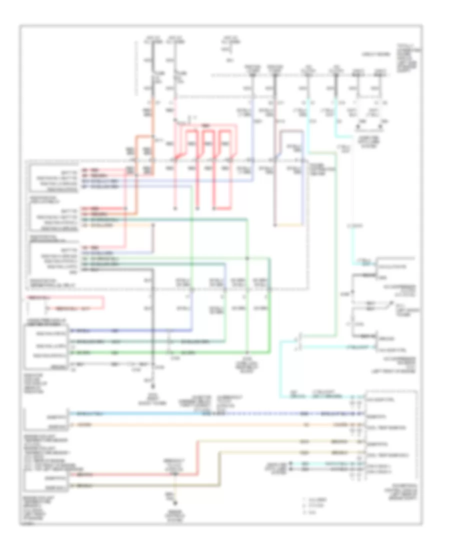
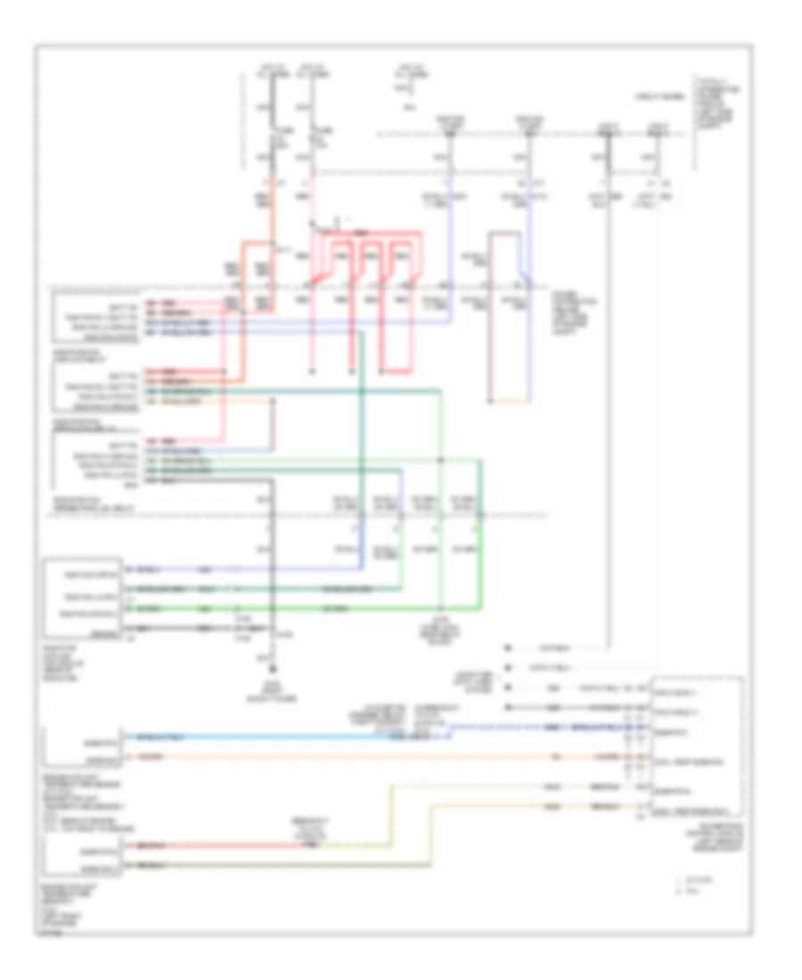
Automatic A/C Wiring Diagram (1 of 2) for Dodge Avenger R/T 2010
 https://portal-diagnostov.com/license.html
Automotive Electricians Portal FZCO
Automotive Electricians Portal FZCO
https://portal-diagnostov.com/license.html
https://portal-diagnostov.com/license.html
Automotive Electricians Portal FZCO
Automotive Electricians Portal FZCO
List of elements for Automatic A/C Wiring Diagram (1 of 2) for Dodge Avenger R/T 2010:
- (above left side of glove box) s202
- (near breakout to instrument cluster) s212
- A/c pressure sens fd
- A/c pressure sens rtn
- A/c pressure sens sig
- A/c pressure transducer (right front of engine compt)
- A/c-heater control
- A417
- Abmt temp fcm ssr rtn1
- Act com
- Act temp
- Ambient air temperature sensor (right side of front bumper beam)
- Auto hd2p sig
- Auto headlamps sig
- B(+)
- Blend door actuator (left side of hvac)
- Blower motor (right side of dash)
- Blower power module
- C108
- C11
- C114
- C121
- C18
- C200
- C21
- C305
- C315
- C32
- C34
- C35
- C56
- C61
- C818
- C83
- C830
- C918
- Can b bus (+)
- Can b bus (-)
- Circuit board
- Computer data lines system
- Convertible
- D54
- D55
- Drv act temp
- End of dash)
- Evap sig
- Evap sns rtn
- Evap snsr rtn
- Evaporator temp sens sig
- Evaporator temperature sensor (left side of hvac)
- F929
- Ft blw fd
- Ft blw pwm ctrl
- Ft mode act drv
- Ft pwm blw pwr
- Fuse 10a
- Fuse 30a
- G200 (left
- G250 (left side of center stack support)
- G31
- G931
- G939
- Gnd
- Gnd ft pwm blw pwr
- Ground
- Hot at all times
- Ignr
- Ignr pre
- Infrared sensor (center of header)
- Iod fd
- Ir sens return
- Ir sens sig
- L24
- Mode door actuator (middle of hvac)
- Nca
- Rcrc act dr
- Recirculation door actuator (right side of hvac)
- Recirculation door drv (a)
- Run/ start ign
- Run/start ign
- S116
- S120b
- S201 (behind left side of glove box)
- S221
- S348 (sedan)
- S355 (convertible)
- Sedan
- Snsr abmt temp sig
- Snsr ir rtn
- Snsr ir sig
- Snsr sunld rtn
- Ssr rtn1
- Sun sens return
- Sun sensor
- Temp sig
- Totally integrated power module (left side of engine compt)
- W/ hands free
- Z134
- Z910
- Z912
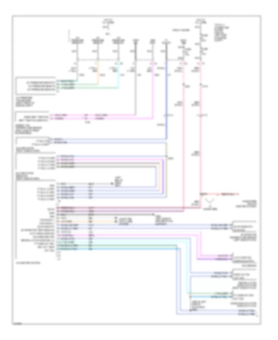
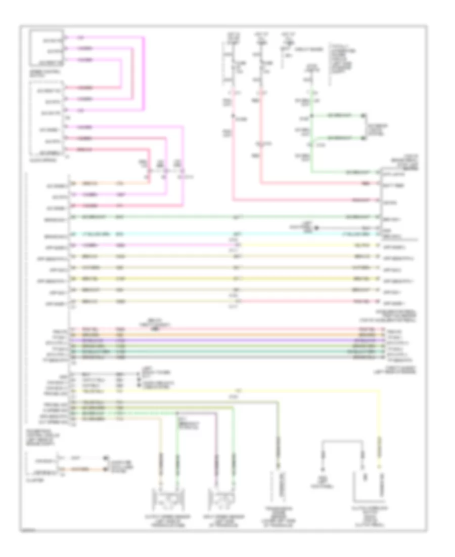
Automatic A/C Wiring Diagram (2 of 2) for Dodge Avenger R/T 2010
List of elements for Automatic A/C Wiring Diagram (2 of 2) for Dodge Avenger R/T 2010:
- (breakout to c101 & pcm c2) s184
- (in breakout to c101 & pcm c2) (2.4l) s181
- (injector harness, below throttle body) (2.7l/3.5l) s182
- 2.4l
- 2.4l dohc
- 2.7l/3.5l
- A/c clutch coil
- A/c clutch fd
- A/c comp ctrl
- A/c compressor clutch (2.7l & 3.5l)
- A/c compressor solenoid (2.4l) (left front of engine)
- A10
- B(+)
- B10
- Batt fd
- C10
- C101
- C103
- C105
- C108
- C11
- C13
- C27 (or c13)
- Can c bus (+)
- Can c bus (-)
- Circuit board
- Computer data lines system
- Cool temp snsr sig
- Cool temp snsr sig 2
- D64
- D65
- Engine controls system
- Engine coolant temperature sensor (2.7l/3.5l) engine coolant temperature sensor 1 (2.4l dohc) (2.4l: rear of engine) (2.7l: top front of engine) (3.5l: top left rear of engine)
- Engine coolant temperature sensor 2 (2.4l dohc) (left front of engine)
- Fuse 10a
- Fuse 40a
- G102 (right shock tower)
- G111 (left shock
- Gnd
- Ground
- Hands free module (center of dash)
- Hot at all times
- K222
- K900
- K915
- N112
- N201
- N210
- N23
- N24
- Nca
- Power distribution center
- Powertrain control module (left rear of engine compt)
- Rad fan hi spd sig
- Rad fan lo rtn
- Rad fan lo spd sig
- Rad fan mtr fd
- Rad fan mtr fd 2
- Rad fan rly batt fd
- Radiator cooling fan module (rear of radiator)
- Radiator fan high/low relay
- Radiator fan medium/high relay
- Radiator fan series/parallel relay
- Red
- S110
- S111
- S125 (wire loom, near relay block)
- S135
- S199
- Snsr rtn
- Snsr rtn3
- Snsr sig
- Snsr sig 2
- Totally integrated power module (left side of engine compt)
- Tower)
- Z901
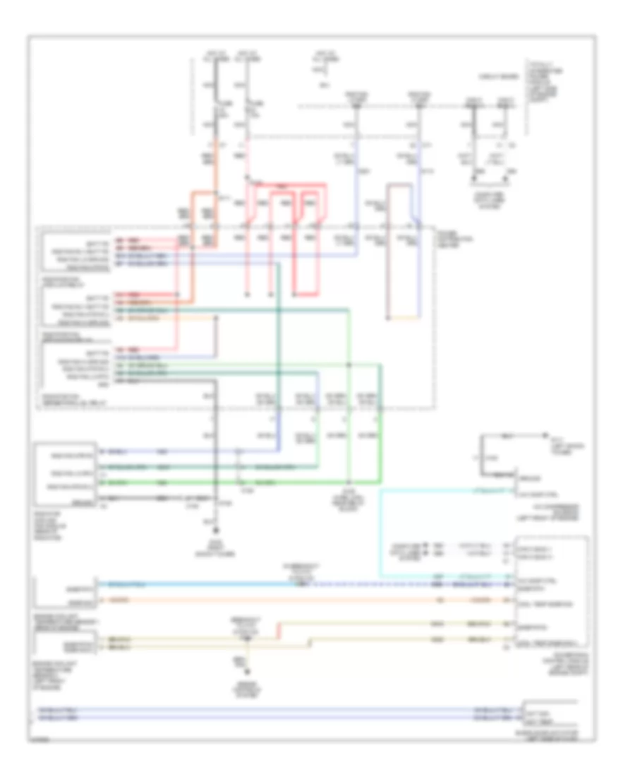
Manual A/C Wiring Diagram (1 of 2) for Dodge Avenger R/T 2010
List of elements for Manual A/C Wiring Diagram (1 of 2) for Dodge Avenger R/T 2010:
- (above left side of glove box) s202
- (left
- A/c pressure sens fd
- A/c pressure sens rtn
- A/c pressure sens sig
- A/c pressure transducer (right front of engine compt)
- A/c-heater control
- A417
- Abmt temp fcm ssr rtn1
- Act com
- Ambient air temperature sensor (right side of front bumper beam)
- Auto hd2p sig
- Auto headlamps sig
- B(+)
- Blower motor (right side of dash)
- Blower motor resistor (right side of dash)
- C108
- C114
- C121
- C18
- C21
- C32
- C34
- C35
- C61
- C70
- C71
- C72
- C73
- C818
- C918
- Can b bus (+)
- Can b bus (-)
- Circuit board
- Computer data lines system
- D54
- D55
- Drv act temp
- End of dash) g200
- Evap sig
- Evap sns rtn
- Evap snsr rtn
- Evaporator temp sens sig
- Evaporator temperature sensor (left side of hvac)
- F929
- Ft blw fd
- Ft blw hi spd
- Ft blw lo spd
- Ft blw m1 spd
- Ft blw m2 spd
- Ft mode act drv
- Fuse 10a
- Fuse 30a
- G250 (left side of center stack support)
- G31
- G931
- G939
- Gnd
- Hands free module (center of dash)
- Hot at all times
- Ign r pre
- Ignr
- Iod fd
- L24
- Mode door actuator (middle of hvac)
- Nca
- Rcrc act dr
- Recirculation door actuator (right side of hvac)
- Recirculation door drv (a)
- S116
- S203
- S212
- S221
- Snsr abmt temp sig
- Snsr sunld rtn
- Ssr rtn1
- Sun sens return
- Sun sensor
- Temp sig
- Totally integrated power module (left side of engine compt)
- W/ hands free
- Z910
- Z912
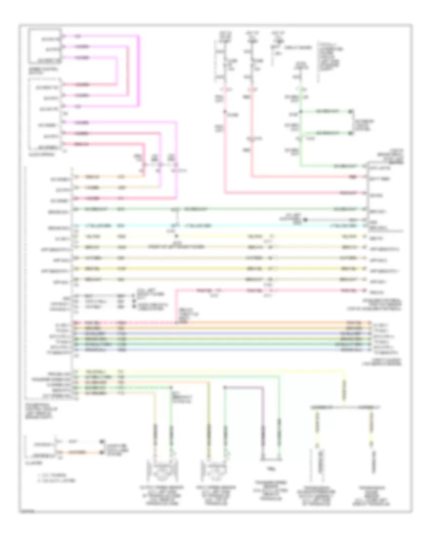
Manual A/C Wiring Diagram (2 of 2) for Dodge Avenger R/T 2010
List of elements for Manual A/C Wiring Diagram (2 of 2) for Dodge Avenger R/T 2010:
- (breakout to c101 & pcm c2) s184
- (in breakout to c101 & pcm c2) s181
- A/c comp ctrl
- A/c compressor solenoid (left front of engine)
- A10
- Act com
- Act temp
- B(+)
- B10
- Batt fd
- Blend door actuator (left side of hvac)
- C103
- C105
- C108
- C11
- C27
- Can c bus (+)
- Can c bus (-)
- Circuit board
- Computer data lines system
- Cool temp snsr sig
- Cool temp snsr sig 2
- D64
- D65
- Engine controls system
- Engine coolant temperature sensor 1 (rear of engine)
- Engine coolant temperature sensor 2 (left front of engine)
- Fuse 10a
- Fuse 40a
- G102 (right shock tower)
- G111 (left shock
- Gnd
- Ground
- Hot at all times
- K222
- K900
- K915
- N112
- N201
- N210
- N23
- N24
- Nca
- Power distribution center
- Powertrain control module (left rear of engine compt)
- Rad fan hi spd sig
- Rad fan lo rtn
- Rad fan lo spd sig
- Rad fan mtr fd
- Rad fan mtr fd 2
- Rad fan rly batt fd
- Radiator cooling fan module (rear of radiator)
- Radiator fan high/low relay
- Radiator fan medium/high relay
- Radiator fan series/parallel relay
- Red
- S110
- S111
- S125 (wire loom, near relay block)
- S135
- Snsr rtn
- Snsr rtn3
- Snsr rtn3 snsr sig 2
- Snsr sig
- Totally integrated power module (left side of engine compt)
- Tower)
- Z901
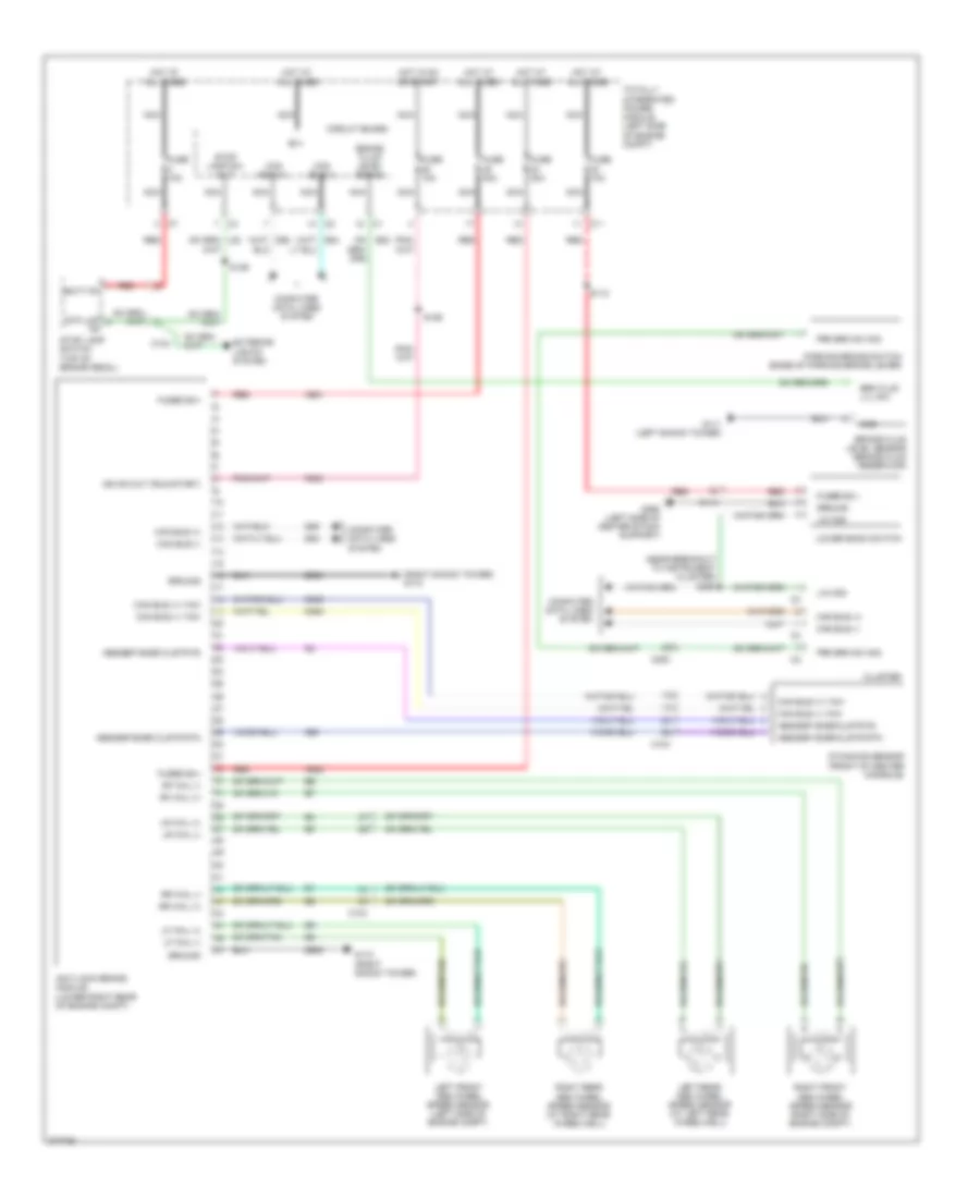
ANTI-LOCK BRAKES
Anti-lock Brakes Wiring Diagram for Dodge Avenger R/T 2010
List of elements for Anti-lock Brakes Wiring Diagram for Dodge Avenger R/T 2010:
- (near breakout to instrument cluster) s260
- (right shock tower) g110
- A921
- A922
- Abs/esp snsr clstr fd
- Abs/esp snsr clstr rtn
- Anti-lock brake module (lower right rear of engine compt)
- B(+)
- B20
- Batt fd
- Brake fluid level sensor (brake fluid reservoir)
- Brake fluid level signal
- Brk flud lvl sw
- C104
- C11
- C114
- C200
- Can bus (+)
- Can bus (+) yaw
- Can bus (-)
- Can bus (-) yaw
- Circuit board
- Cluster
- Computer data lines system
- D464
- D465
- D64
- D65
- Dynamics sensor (front of center console)
- Exterior lights system
- F202
- Fuse 10a
- Fuse 30a
- Fuse 40a
- Fused b(+)
- G110 (right shock tower)
- G111 (left shock tower)
- G250 (left side of center stack support)
- G94
- Gnd
- Ground
- Hot at all times
- Hot in on or start
- Ign sw out (run-start)
- Left front abs wheel speed sensor (left side of engine compt)
- Left rear abs wheel speed sensor (at left rear wheelwell)
- Lf whl (+)
- Lf whl (-)
- Lin ccn
- Lower bank switch
- Lr whl (+)
- Lr whl (-)
- Nca
- Parking brake switch (base of parking brake lever)
- Prk brk sw sig
- Red
- Rf whl (+)
- Rf whl (-)
- Right front abs wheel speed sensor (right side of engine compt)
- Right rear abs wheel speed sensor (at right rear wheelwell)
- Rr whl (+)
- Rr whl (-)
- S110
- S126
- S129
- Stop lamp sw out
- Stop lamp switch (top of brake pedal)
- Stp lmp
- Totally integrated power module (left side of engine compt)
- Z905
ANTI-THEFT
Anti-theft Wiring Diagram (1 of 2) for Dodge Avenger R/T 2010
List of elements for Anti-theft Wiring Diagram (1 of 2) for Dodge Avenger R/T 2010:
- (center instrument panel near ignition switch)
- (left end of dash) g200
- (left kick panel)
- A937
- A952
- B(+)
- Batt feed
- C11
- C114
- C200
- C301
- C302
- C304
- Can bus (+)
- Can bus (-)
- Circuit board
- Cluster
- Computer data lines system
- D508
- D54
- D55
- Dckld/liftgte rel sw sig
- Dr ajar lt rr sig
- Dr ajar rt rr sig
- Dr lck mtr unlck pos driv
- Dr lck mtr unlck pos pass
- Dr lck mtr unlock pos driv
- Dr lk mtr b+ lk
- Dr lk mux driv
- Dr lk mux pass
- Dr lt mtr b+ lk
- Driv ft dr ajar sw in
- Driver door latch (left front door)
- Driver door module
- F20
- F892
- G200 (left end of dash)
- G302
- G302 (left kick panel)
- G306 (right kick panel)
- Gnd
- Headlights system
- Horn drv
- Horn drv 2
- Horns system
- Hot at all times
- Ign run st
- Ign run st sw snse
- Ignition switch
- Iod fd
- L33
- L34
- L43
- L44
- Lgate ajar sig
- Lgate pwr rel
- Lin tire press
- Lt hi beam fd
- Lt lo beam fd
- Nca
- Pass ft dr ajar sw in
- Passenger door latch (right front door)
- Pnk
- Q15
- Red
- Red/tan
- Rt hi beam fd
- Rt lo beam fd
- S211
- S220
- S261
- S353
- S359
- S369
- Securty fd to strg lk mod
- Steering column lock module (steering column)
- Sw pwr wdw lk out fd
- Totally integrated power module (left side of engine compt)
- Unlck pos pass dr lck mtr
- Warning systems
- Wireless ignition node
- X21
- X22
- Z908
- Z910
Anti-theft Wiring Diagram (2 of 2) for Dodge Avenger R/T 2010
List of elements for Anti-theft Wiring Diagram (2 of 2) for Dodge Avenger R/T 2010:
- (center of left door module) s351
- (near right kick panel) s303
- A937
- Ajar sig lgate
- B+ lk dr lt mtr
- Batt feed
- C104
- C108
- C11
- C114
- C200
- C301
- C302
- C303
- C304
- C308
- C309
- Can bus (+)
- Can bus (-)
- Cargo lamp
- Circuit board
- Computer data lines system
- D54
- D55
- Decklid door latch (center rear of deck lid)
- Decklid release switch
- Dr ajar lt rr sig
- Dr ajar rt rr sig
- Dr lck mtr unlck pos pass
- Dr lk mux driv
- Dr lk mux pass
- Dr lt mtr b+ lk
- Driver express window/door lock switch
- Fuse 10a
- Fuse 20a
- Fuse 30a
- G105 (right shock tower)
- G200 (left end of dash)
- G300 (center floor, right of tunnel)
- G301 (base of left "b" pillar)
- G302 (left kick panel)
- G304 (near decklid latch)
- G306 (right kick panel)
- G70
- Gnd
- Hood ajar switch (right front of engine compt)
- Hot at all times
- Left rear door latch (left rear door)
- Left rear power window switch
- Lgate ajar sig
- Lgate pwr rel
- Nca
- Passenger door module
- Passenger window/ door lock switch
- Red
- Red/tan
- Right rear door latch (left rear door)
- Right rear power window switch
- S200
- S210
- S312
- S353
- S369
- S371
- Sw pwr wdw lk out fd
- Sw sig
- Totally integrated power module (left side of engine compt)
- Uhood sw sig
- Unlck pos pass dr lck mtr
- Z908
BODY CONTROL MODULES
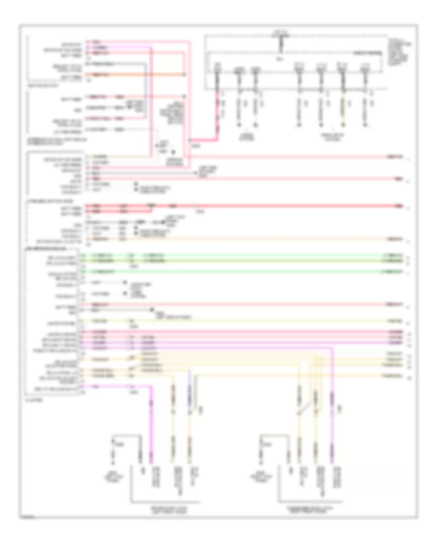
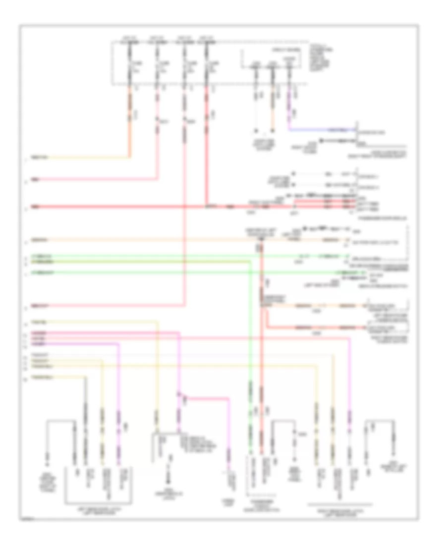
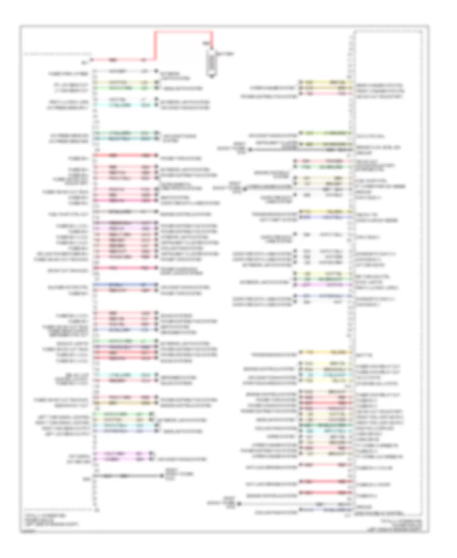
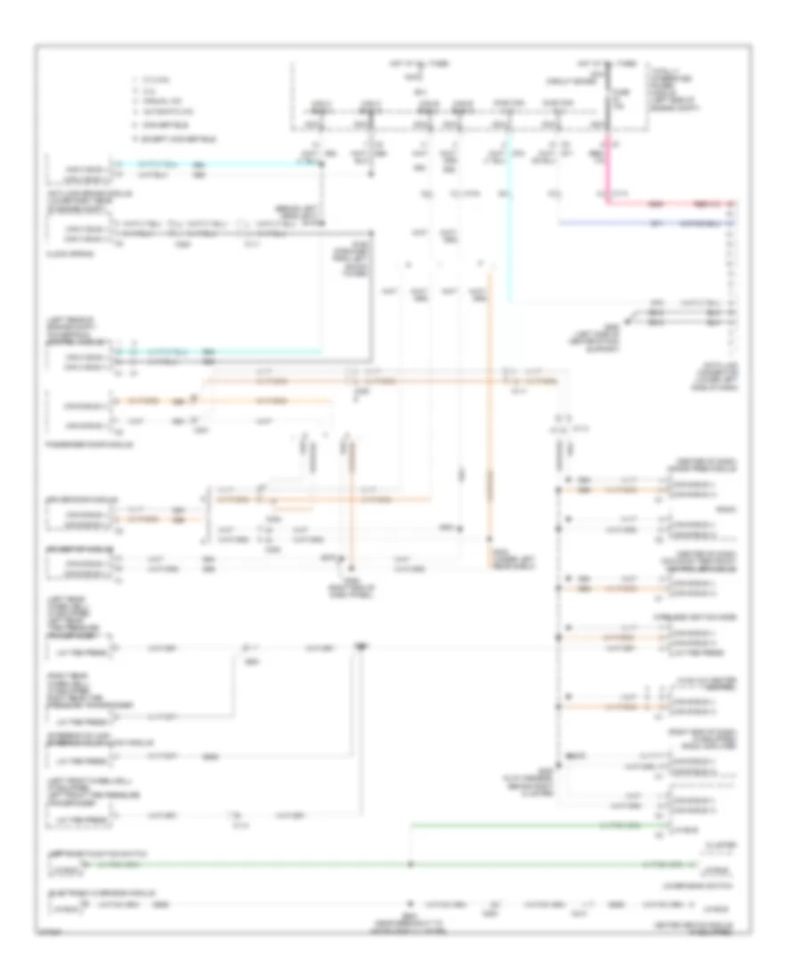
Body Control Modules Wiring Diagram for Dodge Avenger R/T 2010
List of elements for Body Control Modules Wiring Diagram for Dodge Avenger R/T 2010:
- (right shock tower) g102
- A/c cltch coil
- A/c press sens gnd
- A/c press sens sig
- A/c press sens sply
- A14
- A16
- A411
- A412
- A413
- A417
- A418
- A419
- A420
- A921
- A922
- A924
- A925
- A926
- A927
- A929
- A931
- A932
- A933
- A935
- A937
- A950
- A952
- Aat return
- Aat signal
- Ac cltch fd
- Air conditioning system
- Anti-lock brakes system
- Anti-theft system
- Asd rly fd
- Asd/main rly out
- B(+)
- B20
- Backup lamp fd
- Batt fd
- Battery
- Blower motor ctrl
- Brake fluid level sig
- C10
- C11
- C13
- C16
- C18
- C515
- C818
- C918
- Can b bus (+)
- Can b bus (-)
- Can c bus (+)
- Can c bus (-)
- Computer data lines system
- Cooling fans system
- D54
- D55
- D64
- D65
- D71
- D72
- Defogger system
- Diagnostic can c (+)
- Diagnostic can c (-)
- Dr lock power-fused b(+)
- Ebl rly o/p control output fused b(+) (i.o.d.)
- Engine controls system
- Exterior lights system
- F100
- F20
- F200
- F202
- F342
- F343
- F344
- F901
- F929
- F937
- F981
- F986
- F996
- Front fog lamp ind fd 2
- Front washer mtr ctrl
- Ft wiper hi speed fd
- Ft wiper low speed fd
- Ft wiper park sw sense
- Fuel pump ctrl
- Fuel pump ctrl out
- Fused b (+)
- Fused b (+) (pump)
- Fused b (+) (valve)
- Fused b(+)
- Fused b(+) (i.o.d.)
- Fused b(+) fused ign sw out (run-start)
- Fused ign sw out (run)
- Fused ign sw out (run) fused rear window defogger ctrl out
- Fused ign sw out (run-acc)
- Fused main relay out
- Fused park lp feed
- G31
- G70
- G931
- Gnd
- Ground
- Headlights system
- Hood ajar sw sense
- Horn drive
- Horn drive 2
- Horns system
- Ign sw out (run-acc)
- Ign sw out (run-start)
- Ign sw out (unlock-run-start) starter ctrl
- Instrument cluster system
- Interior lights system
- K31
- K542
- L217
- L33
- L34
- L43
- L44
- L53
- L60
- L61
- L62
- L63
- L70
- L89
- L90
- Left low beam output
- Left turn signal control
- Lr turn sig fd
- Lt high beam out
- N112
- N201
- Pnk
- Pnk/red
- Power distribution system
- Power tops system
- Power windows & door locks systems
- Power windows system
- Prk/tl/lk row lmps
- Prk/tl/lk row lmps 2
- Rad fan lo spd sig
- Rad fan relay control
- Rear washer mtr ctrl
- Red
- Red/pnk
- Red/tan
- Right high beam output
- Right turn signal control
- Rr turn sig ctrl
- Rt low beam out
- Seats system
- Sound systems
- Starter coil mtr fd
- Starting/charging system
- Stop lamp fd
- T15
- T16
- T750
- T752
- Totally integrated power module (left side of engine compt)
- Transmissions system
- W10
- W20
- Wiper/washer system
- X21
- X22
- Z901
COMPUTER DATA LINES
Computer Data Lines Wiring Diagram for Dodge Avenger R/T 2010
List of elements for Computer Data Lines Wiring Diagram for Dodge Avenger R/T 2010:
- (behind left headlight) s175
- (center of dash) hands free module
- (center of dash) occupant restraint controller module
- (left front wheelwell) (if equipped) left front tire pressure transponder
- (left rear of engine compt) powertrain control module
- (left rear wheelwell) (if equipped) left rear tire pressure transponder
- (right end of dash) (if equipped) radio amplifier
- (right rear wheelwell) (if equipped) right rear tire pressure transponder
- (steering column) steering column lock module
- 2.4l
- 2.7l/3.5l
- A933
- Anti-lock brake module (lower right rear of engine compt)
- Automatic a/c
- B(+)
- C104
- C111
- C114
- C200
- C214
- C300
- C301
- C302
- C304
- Can b bus (+)
- Can b bus (-)
- Can c bus (+)
- Can c bus (-)
- Circuit board
- Clock spring
- Cluster
- Convertible
- D506
- D508
- D54
- D55
- D64
- D65
- D71
- D72
- Data link connector (lower left side of dash)
- Diag can c (+)
- Diag can c (-)
- Driver door module
- Electronic overhead module
- Except convertible
- Fuse 10a
- G250 (left side of center stack support)
- Heated seats module (if equipped)
- Hot at all times
- Hvac a/c heater control
- Left multi-function switch
- Lin bus
- Lin tire press
- Lower bank switch
- Manual a/c
- Nca
- Passenger door module
- Power top module
- Radio
- S185 (forward from left shock tower)
- S260 (near breakout to instrument cluster)
- S261
- S270
- S280 (in ip harness, behind right cluster)
- S301
- S302 (under left rear shelf)
- S370
- S380 (right end of dash panel)
- Totally integrated power module (left side of engine compt)
- Wireless ignition node
- Z912
COOLING FAN
Cooling Fan Wiring Diagram for Dodge Avenger R/T 2010
List of elements for Cooling Fan Wiring Diagram for Dodge Avenger R/T 2010:
- (breakout to c101 & pcm c2) s184
- (in breakout to c101 & pcm c2) (2.4l) s181
- (in injector harness, below throttle body) (2.7l/3.5l) s182
- 2.4l
- 2.7l/3.5l
- A10
- B(+)
- B10
- Batt fd
- C105
- C108
- C11
- Can c bus (+)
- Can c bus (-)
- Circuit board
- Computer data lines system
- Cool temp snsr sig
- Cool temp snsr sig 2
- D64
- D65
- Engine coolant temperature sensor (2.7l/3.5l) engine coolant temperature sensor 1 (2.4l) (2.4l: rear of engine) (2.7l: top front of engine)
- Engine coolant temperature sensor 2 (2.4l) (left front of engine)
- Fuse 10a
- Fuse 40a
- G102 (right shock tower)
- Gnd
- Ground
- Hot at all times
- K222
- K900
- K915
- N210
- N23
- N24
- Nca
- Power distribution center (left side of engine compt)
- Powertrain control module (left rear of engine compt)
- Rad fan hi spd sig
- Rad fan lo rtn
- Rad fan lo spd sig
- Rad fan mtr fd
- Rad fan mtr fd 2
- Rad fan rly batt fd
- Radiator cooling fan module (rear of radiator)
- Radiator fan high/low relay
- Radiator fan medium/high relay
- Radiator fan series/parallel relay
- Red
- S110
- S111
- S125 (wire loom, near relay block)
- S135
- Snsr rtn
- Snsr rtn3
- Snsr sig
- Snsr sig 2
- Totally integrated power module (left side of engine compt)
- Z901
CRUISE CONTROL
2.4L
2.4L, Cruise Control Wiring Diagram for Dodge Avenger R/T 2010
List of elements for 2.4L, Cruise Control Wiring Diagram for Dodge Avenger R/T 2010:
- (below throttle body) s192
- (left kick panel) g302
- (left shock tower) g111
- (top of brake pedal) stop lamp switch
- Accelerator pedal position sensor (top of accelerator pedal)
- App sens rtn 1
- App sens rtn 2
- App sig 1
- App sig 2
- App snsr 1
- App snsr 2
- B(+)
- B15
- B16
- Batt feed
- Brake sig 1
- Brake sig 2
- Brk sig 1
- Brk sig 2
- C104
- C11
- C111
- C114
- Can bus (+)
- Can bus (-)
- Circuit board
- Clock spring
- Cluster
- Clutch interlock switch (dohc) (top of clutch pedal)
- Computer data lines system
- D64
- D65
- Etc mtr (+)
- Etc mtr (-)
- Exterior lights system
- F855
- Fuse 10a
- G302 (left kick panel)
- Gnd
- Hot at all times
- Hot in on or start
- Ign r/s
- In speed sig
- Input speed sensor (left side of transaxle)
- K122
- K124
- K126
- K167
- K22
- K23
- K29
- K400
- K852
- K854
- K922
- Nca
- Out speed sig
- Output speed sensor (left side of transaxle case)
- Powertrain control module (left rear of engine compt)
- Prim fd
- Prk/neu sig
- Red
- S/c rdnt fd
- S/c rtn
- S/c snse 1
- S/c snse 2
- S/c sw fd
- S120b
- S129
- S171 (breakout to pcm c4)
- Spd sens rtn
- Speed control switch
- Stop lamp fd
- Stp lmp fd
- T13
- T14
- T41
- T52
- Throttle body (left rear of engine)
- Totally integrated power module (left side of engine compt)
- Tp sens rtn
- Tp sig 1
- Tp sig 2
- Transmission range sensor (lower left side of transaxle)
- V71
- V72
- V937
- Z931
3.5L
3.5L, Cruise Control Wiring Diagram for Dodge Avenger R/T 2010
List of elements for 3.5L, Cruise Control Wiring Diagram for Dodge Avenger R/T 2010:
- (3.5l: left shock tower) g111
- (at left kick panel) g302
- (below throttle body) s192
- (top of brake pedal) stop lamp switch
- 2.7l touring
- 3.5l & 2.7l limited
- 4-speed a/t
- 5v sply
- 6-speed a/t
- Accelerator pedal position sensor (top of accelerator pedal)
- App sens rtn 1
- App sens rtn 2
- App sig 1
- App sig 2
- B(+)
- B15
- B16
- Batt feed
- Brake sig 1
- Brake sig 2
- Brk sig 1
- Brk sig 2
- C101
- C104
- C11
- C111
- C114
- Can bus (+)
- Can bus (-)
- Circuit board
- Clock spring
- Cluster
- Computer data lines system
- D64
- D65
- Etc mtr (+)
- Etc mtr (-)
- Exterior lights system
- F855
- F856
- Fuse 10a
- Gnd
- Hot at all times
- Hot in on or start
- Ign r/s
- In speed sig
- Input speed sensor (2.7l: left side of transaxle) (3.5l: top of transaxle)
- K122
- K124
- K126
- K167
- K22
- K23
- K29
- K400
- K922
- Nca
- Out speed sig
- Output speed sensor (2.7l: left side of transaxle case) (3.5l: rear of transaxle case)
- Powertrain control module (left rear of engine compt)
- Prim fd
- Prk/neu sig
- Red
- S/c rdnt fd
- S/c rtn
- S/c snse 1
- S/c snse 2
- S/c sw fd
- S120b
- S123 (front of left shock tower)
- S129
- S171 (breakout to pcm c4)
- Sec fd
- Sens rtn
- Speed control switch
- Stop lamp fd
- Stp lmp fd
- T13
- T14
- T41
- T52
- T85
- Throttle body (top rear of engine)
- Totally integrated power module (left side of engine compt)
- Tp sens rtn
- Tp sig 1
- Tp sig 2
- Transfer speed sensor (3.5l & 2.7l limited) (rear of transaxle)
- Transfer speed sig
- Transmission range sensor (2.7l: lower left side of transaxle)
- Transmission solenoid/pressure switch assembly (2.7l: left side of transaxle)
- V71
- V72
- V937
- Z931
DEFOGGERS
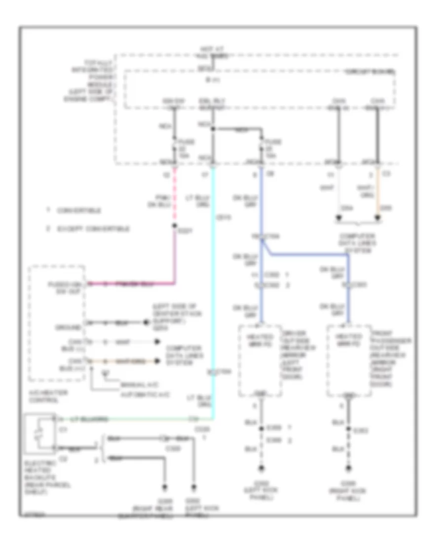
Defoggers Wiring Diagram for Dodge Avenger R/T 2010
List of elements for Defoggers Wiring Diagram for Dodge Avenger R/T 2010:
- (left side of center stack support) g250
- A/c-heater control
- Automatic a/c
- B (+)
- Bus (+)
- Bus (-)
- C104
- C302
- C303
- C320
- C515
- Can
- Can bus (+)
- Can bus (-)
- Circuit board
- Computer data lines system
- Convertible
- D54
- D55
- Driver outside rearview mirror (left front door)
- Ebl rly output
- Electric heated backlite (rear parcel shelf)
- Except convertible
- Front passenger outside rearview mirror (right front door)
- Fuse 10a
- Fused ign sw out
- G302 (left kick panel)
- G305 (right rear quarter panel)
- G306 (right kick panel)
- Gnd
- Ground
- Heated mrr fd
- Hot at all times
- Ign sw out
- Manual a/c
- Nca
- S221
- S353
- S359
- S369
- Totally integrated power module (left side of engine compt)
ENGINE PERFORMANCE
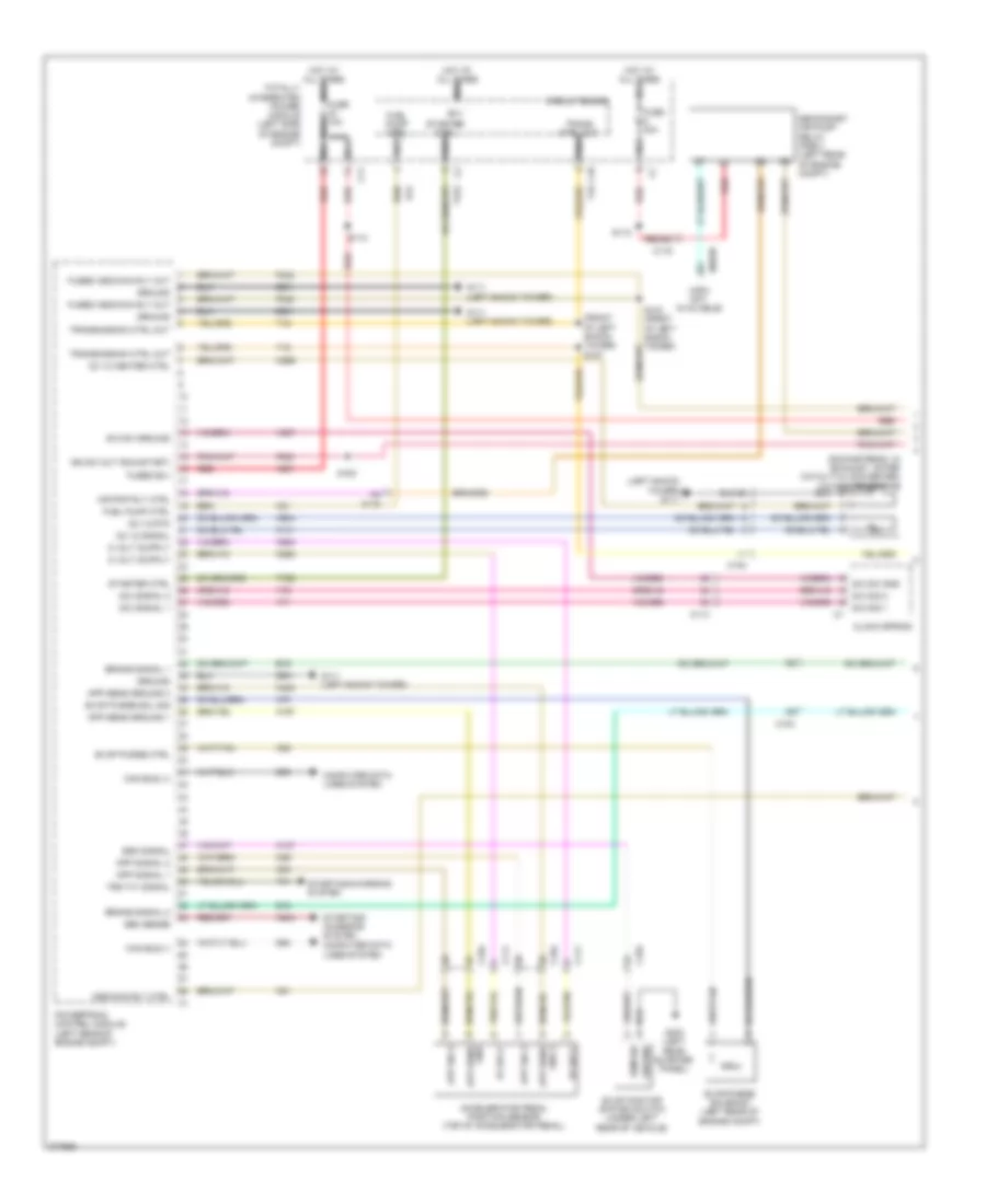
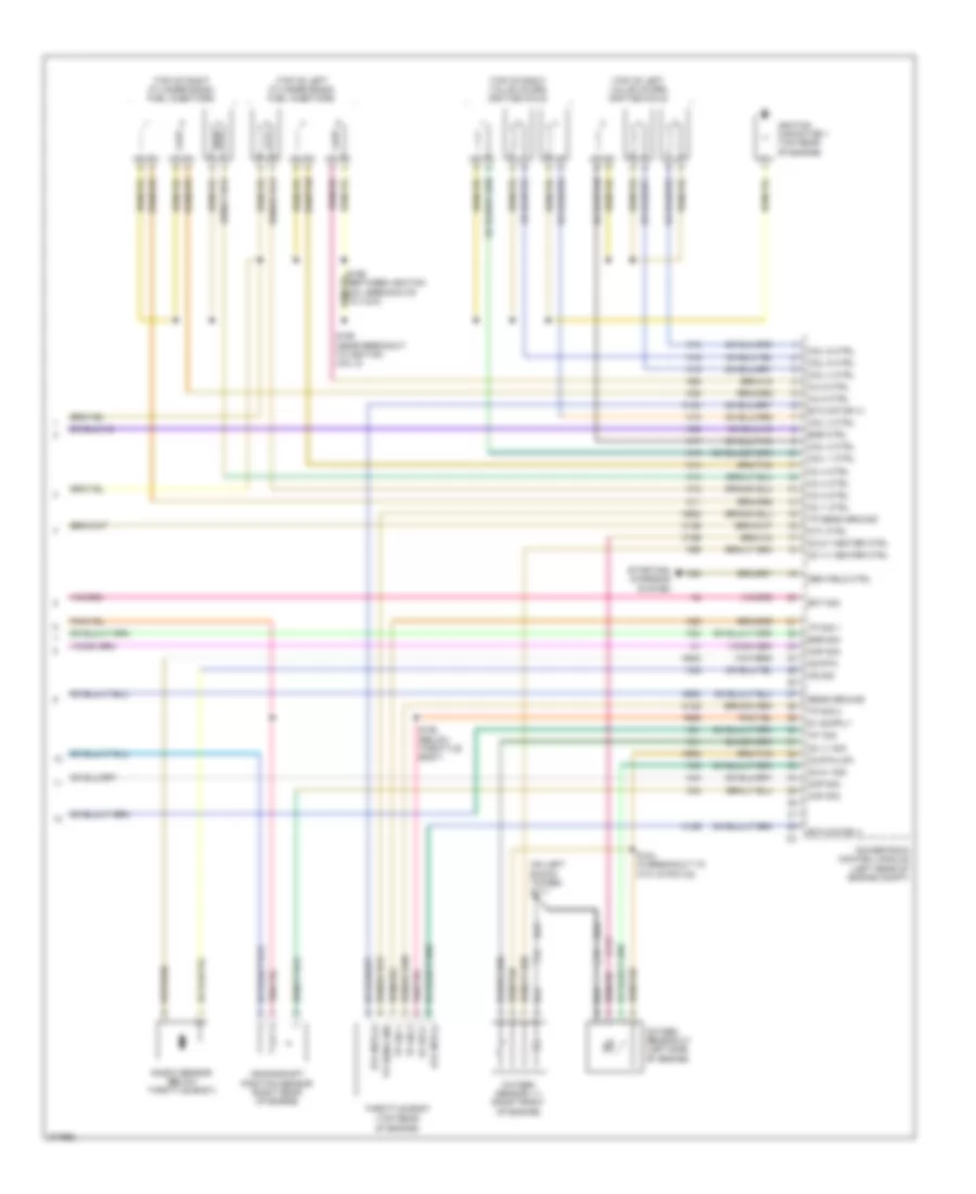
2.4L
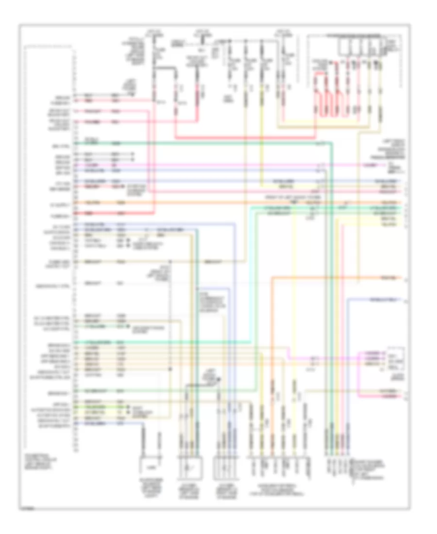
2.4L, Engine Performance Wiring Diagram (1 of 4) for Dodge Avenger R/T 2010
List of elements for 2.4L, Engine Performance Wiring Diagram (1 of 4) for Dodge Avenger R/T 2010:
- (downstream: in exhaust, after catalytic converter) oxygen sensor 1/2
- (front of left shock tower) s127
- (info not available)
- (left shock tower) g111
- 5v sply
- A4 c118
- A804
- A931
- Accelerator pedal position sensor (top of accelerator pedal)
- Air pmp rly ctrl
- App sens ground 1
- App sens ground 2
- App sig 2
- App signal 1
- App signal 2
- Asd/main rly ctrl
- B(+)
- B15
- B16
- Brake signal 1
- Brake signal 2
- C10
- C103
- C104
- C11
- C111
- C114
- C119
- Can bus (+)
- Can bus (-)
- Circuit board
- Clock spring
- Computer data lines system
- D64
- D65
- Esm sig
- Esm signal
- Evap monitor system switch (under left rear of vehicle)
- Evap purge ctrl
- Evap purge sol sig
- Evap/purge solenoid (left rear of engine compt)
- F202
- F342
- Fuel pump ctrl
- Fuse 10a
- Fuse 40a
- Fused asd/main rly out
- Fused b(+)
- G111 (left shock tower)
- G303 (left rear quarter panel)
- Gen sense
- Gnd 2 app sens
- Gnd app sens
- Ground
- Hot at all times nca
- I6693b
- Ign sw out (run-start)
- K107
- K141
- K167
- K23
- K29
- K299
- K31
- K400
- K51
- K52
- K70
- K852
- K854
- K904
- Nca
- O2 1/2 heater ctrl
- O2 1/2 rtn
- O2 1/2 signal
- Powertrain control module (left rear of engine compt)
- Red
- S/c sig 1
- S/c sig 2
- S/c signal 1
- S/c signal 2
- S/c sw gnd
- S/c sw ground
- S110
- S112
- S153
- Secondary air pump relay (pzev) (left rear of engine compt)
- Starter ctrl
- Starting/ charging system
- Starting/charging system
- T16
- T41
- T752
- Totally integrated power module (left side of engine compt)
- Trans ctrl out nca
- Transmission ctrl out
- Trs t41 signal
- V71
- V72
- V937
- Z931
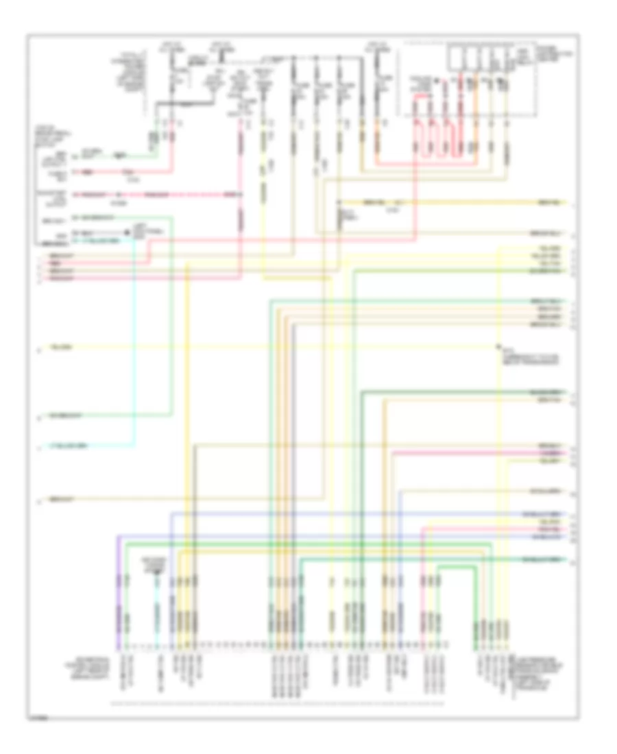
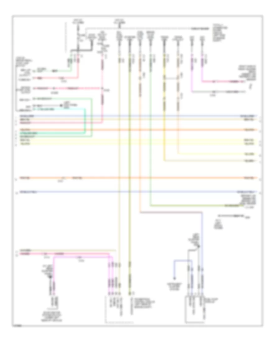
2.4L, Engine Performance Wiring Diagram (2 of 4) for Dodge Avenger R/T 2010
List of elements for 2.4L, Engine Performance Wiring Diagram (2 of 4) for Dodge Avenger R/T 2010:
- (left kick panel) g302
- (top of brake pedal) stop lamp switch
- 2-4 pres sig
- 5v sply
- A/c comp ctrl
- Air condi- tioning system
- Asd rly out
- Asd rly rtn
- Asd/ main relay
- B(+)
- B1 red
- Batt fd
- Brk lmp ctrl output 1
- Brk sig 1
- Brk sig 2
- C10
- C103
- C104
- C11
- C27
- Circuit board
- Cmp sig 2
- Cooling fans system
- Ect 2 sig
- Eot sig
- Etc motor (+)
- Etc motor (-)
- F855
- F856
- Fuse 10a nca
- Fuse 15a nca
- Fuse 30a nca
- Fuse 40a
- Fuse d b(+)
- G24
- Gnd
- Hot at all times
- Hot at all times nca
- Iat sig
- Ign sw out (run- start)
- Injector 1 ctrl
- Injector 2 ctrl
- Injector 3 ctrl
- Injector 4 ctrl
- K11
- K12
- K124
- K126
- K13
- K14
- K21
- K222
- K41
- K441
- K902
- L/r pres sig
- L53
- Line pressure sensor/variable force solenoid assembly (left side of transaxle)
- Lp vfs ctrl
- Lp vfs sig
- Nca
- O2 1/1 return
- O2 1/1 sig
- Od pres sig
- Power distribution center
- Powertrain control module (left rear of engine compt)
- Red
- Run/start ctrl output
- S120b
- S126
- S129
- S172 (in breakout to c106, above transmission)
- Sens gnd
- Stop lamp sw out
- T118
- T15
- T38
- T47
- T50
- T854
- Tans ctrl out
- Totally integrated power module (left side of engine compt)
- Trans ctrl
- Trans ctrl nca
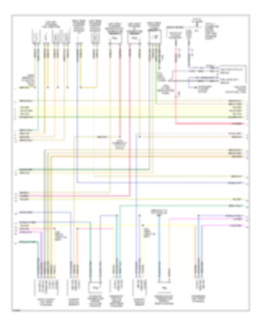
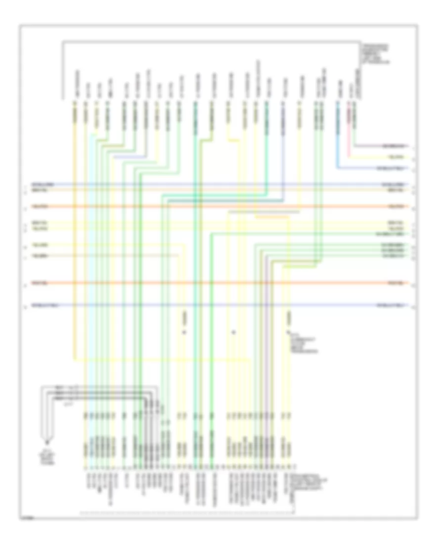
2.4L, Engine Performance Wiring Diagram (3 of 4) for Dodge Avenger R/T 2010
List of elements for 2.4L, Engine Performance Wiring Diagram (3 of 4) for Dodge Avenger R/T 2010:
- (breakout to c101 & pcm c2) s181
- (left front of engine) engine coolant temperature sensor 2
- (left front of engine) oil temperature sensor
- (left rear of engine) camshaft position solenoid 1/1
- (near breakout to ignition coil 5) s190
- (right rear of engine) camshaft position solenoid 1/2
- (right rear of engine) oxygen sensor 1/1
- (top left of engine) fuel injectors
- 5v sply
- B(+)
- C103
- C104
- Camshaft position sensor
- Camshaft position sensor 2
- Circuit board
- Ckp sig
- Cmp 2 sig
- Cmp sig
- Crankshaft position sensor (right rear of engine)
- Engine coolant temperature sensor 1 (rear of engine)
- Etc mtr (+)
- Etc mtr (-)
- F901
- Fuel level sig 1
- Fuel pump ctrl out
- Fuel pump module (top of fuel tank)
- G111 (left shock tower)
- G303 (at left rear quarter panel)
- Ground
- Hot at all times nca
- Ign sw out (unlock- run-start)
- Instrument cluster system
- Intake air temperature sensor (on intake manifold)
- Map sensor (left front of engine)
- Map sig
- Nca
- Pnk/red
- S184 (in breakout to c101 & pcm c2)
- S191 (near throttle body)
- S192 (below throttle body)
- Sens gnd
- Throttle body (left rear of engine)
- Totally integrated power module (left side of engine compt)
- Tp sens gnd
- Tp sig 1
- Tp sig 2
- Z916
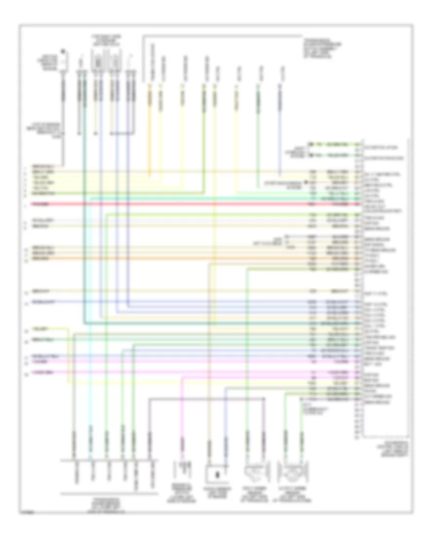
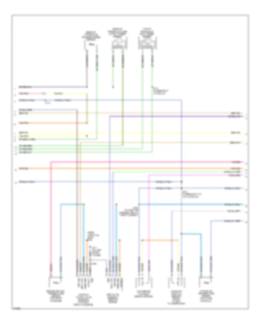
2.4L, Engine Performance Wiring Diagram (4 of 4) for Dodge Avenger R/T 2010
List of elements for 2.4L, Engine Performance Wiring Diagram (4 of 4) for Dodge Avenger R/T 2010:
- (info not available)
- (top of engine, near ignition coil breakout 4) s196
- (top right side of engine) ignition coils
- 2-4 ctrl
- 2-4 press sig
- Autostick down sig
- Autostick up sig
- C103
- Ckp sig
- Cmp 1/1 ctrl
- Cmp 1/2 ctrl
- Cmp sig
- Coil 1 ctrl
- Coil 2 ctrl
- Coil 3 ctrl
- Coil 4 ctrl
- Ect 1 sig
- Engine oil pressure switch (lower left side of engine)
- Eop sig
- F901
- Gen field ctrl
- Ign sw out (unlock-run-start)
- Ignition capacitor (rear of engine)
- In speed sig
- Input speed sensor (on left side of transaxle)
- K122
- K15
- K157
- K17
- K18
- K19
- K20
- K22
- K24
- K276
- K42
- K44
- K76
- K900
- K915
- K922
- K942
- K957
- K99
- Knock sensor (left side of engine)
- Ks return
- Ks sig
- L/r ctrl
- L/r press sig
- Map sig
- O2 1/1 heater ctrl
- Od ctrl
- Od press sig
- Oil press sig
- Out speed sig
- Output speed sensor (on left side of transaxle case)
- Pnk/red
- Powertrain control module (left rear of engine compt)
- Prk/neu sig
- S171 (in breakout to pcm c4)
- Saf signal
- Sens ground
- Shift interlock system
- Spd sens gnd
- Starting/charging system
- T13
- T14
- T19
- T20
- T41
- T42
- T44
- T52
- T54
- T59
- T60
- T853
- Tp sens ground
- Tp sig 1
- Tp sig 2
- Trans ctrl output
- Trans temp sig
- Transmission range sensor (on lower left side of transaxle)
- Transmission solenoid/pressure switch assembly (on left side of transaxle)
- Trs c2 sig
- Trs c3 sig
- Trs c4 sig
- Trs prk/neu sig
- Ud ctrl
3.5L
3.5L, Engine Performance Wiring Diagram (1 of 5) for Dodge Avenger R/T 2010
List of elements for 3.5L, Engine Performance Wiring Diagram (1 of 5) for Dodge Avenger R/T 2010:
- (front of left shock tower) s123
- (left front side of engine block) engine oil pressure switch
- (left shock tower) g111
- (not used)
- (run-start)
- (unlock- run-start)
- 5v sply
- A/c comp ctrl
- A804
- A931
- Accelerator pedal position sensor (top of accelerator pedal)
- Air conditioning system
- App sens gnd 1
- App sens gnd 2
- App sig 1
- App sig 2
- Asd rly out
- Asd rly rtn
- Asd/ main relay
- Asd/main rly ctrl
- Asd/main rly out
- Autostick down sig
- Autostick up sig
- B(+)
- B1 red
- B15
- B16
- Batt fd
- Brake sig 1
- Brake sig 2
- C10
- C101
- C104
- C11
- C111
- C114
- C117
- C13
- Can bus (+)
- Can bus (-)
- Circuit board
- Clock spring
- Computer data lines system
- Cooling fans system
- D64
- D65
- Eop sig
- Evap purge ctrl sig
- Evap purge rtn
- Evap/purge solenoid (left rear of engine compt)
- F202
- F342
- F856
- F901
- Fuse 10a nca
- Fuse 15a
- Fuse 30a
- Fuse 40a
- Fused asd/ main rly out c1
- Fused b(+)
- Gen sense
- Gnd 1 app sens
- Gnd 2 app sens
- Ground
- Hot at all times
- Hot at all times nca
- Ign sw out
- Ign sw out (unlock- run-start)
- K141
- K167
- K23
- K234
- K235
- K236
- K243
- K299
- K399
- K400
- K51
- K52
- K70
- K904
- Mtv sig
- Nca
- O2 1/2 heater ctrl
- O2 1/2 sig
- O2 2/2 heater ctrl
- O2 2/2 sig
- O2 rtn (down)
- Oil press sig
- Oxygen sensor 1/2 (right side of engine)
- Oxygen sensor 2/2 (left side of engine)
- Pnk/red
- Power distribution center
- Powertrain control module (left rear of engine compt)
- Red
- Rly out
- S/c sig 2
- S/c sw gnd
- S103 (front of left shock tower)
- S106 (in breakout to manifold tuning valve solenoid)
- S110
- S114
- Sens gnd
- Shift interlock system
- Short runner valve solenoid (top front of left cylinder bank)
- Sig 1
- Sig 2
- Srv ctrl
- Srv sig
- Starting/ charging system
- Sw gnd
- T44
- Totally integrated power module (left side of engine compt)
- V72
- V937
- Z931
3.5L, Engine Performance Wiring Diagram (2 of 5) for Dodge Avenger R/T 2010
List of elements for 3.5L, Engine Performance Wiring Diagram (2 of 5) for Dodge Avenger R/T 2010:
- (at left rear quarter panel) g303
- (brake fluid reservoir) brake fluid level sensor
- (left kick panel) g302
- (left rear quarter panel) g303
- (right side of front bumper beam) ambient air temperature sensor
- (top of brake pedal) stop lamp switch
- Aat rtn
- Aat sig
- App sig 2
- B(+) fuel pump ctrl nca
- B20
- Brake fluid level sig
- Brk lmp ctrl output 1
- Brk sig 1
- Brk sig 2
- C10
- C101
- C104
- C108
- C11
- C113
- C114
- Circuit board
- Esm sig
- Evap monitor system switch (under left rear of vehicle)
- Fuel level sig
- Fuel pump ctl out fuel pump module
- Fuel pump ctrl
- Fuel pump ctrl out nca
- Fuse 10a
- Fused b(+)
- G111 (left shock tower)
- G31
- G931
- Gnd
- Ground
- Hot at all times
- Hot at all times nca
- Ign run/ start ctrl output
- Ign sw out (run- start)
- Instrument cluster system
- K107
- K29
- K31
- L53
- Lvl sig
- Nca
- Nca fuse 10a nca
- Powertrain control module (left rear of engine compt)
- Red
- S/c sig 1
- S120b
- S126
- S129
- Starter ctrl
- Starter ctrl nca
- Stop lamp sw out nca
- T15
- T16
- T752
- Totally integrated power module (left side of engine compt)
- Trans ctrl nca
- Trans ctrl out nca
- V71
- Z916
3.5L, Engine Performance Wiring Diagram (3 of 5) for Dodge Avenger R/T 2010
List of elements for 3.5L, Engine Performance Wiring Diagram (3 of 5) for Dodge Avenger R/T 2010:
- 2-4 ctrl
- 2-4 lr sol ctrl
- 2-4 press sig
- 2-4 pressure sig
- 5 spd sens gnd
- 5v sply
- C113
- C117
- Dc ctrl
- Dc press sig
- Dc pressure sig
- Emcc ctrl
- G111 (on left shock tower)
- Ground
- Input speed sig
- L/r ctrl
- L/r press sig
- L/r pressure sig
- Lc ctrl
- Lc press sig
- Lc pressure sig
- Line press sig
- Lp vfs ctrl
- Od ctrl
- Od press sig
- Od pressure sig
- Out speed sig
- Powertrain control module (left rear of engine compt)
- Prk/neu sig
- S172 (in breakout to c106, above transmission)
- Sens gnd
- Sens ground
- T118
- T13
- T14
- T15
- T16
- T19
- T20
- T38
- T41
- T42
- T47
- T50
- T52
- T54
- T59
- T60
- T80
- T81
- T82
- T83
- T84
- T85
- Trans ctrl
- Trans ctrl out
- Trans ctrl output
- Trans temp sig
- Transfer spd sig
- Transmission solenoid/trs assembly (left side of transaxle)
- Trs prk/neu sig
- Trs t2 sig
- Trs t22 sig
- Trs t3 sig
- Trs t4 sig
- Ud ctrl
- Z931
3.5L, Engine Performance Wiring Diagram (4 of 5) for Dodge Avenger R/T 2010
List of elements for 3.5L, Engine Performance Wiring Diagram (4 of 5) for Dodge Avenger R/T 2010:
- (near throttle body) s191
- (rear of transaxle case) output speed sensor
- (rear of transaxle) transfer speed sensor
- (top of transaxle) input speed sensor
- 5v sply
- C113
- Camshaft position sensor 1 (front of left cylinder bank)
- Egr sig
- Egr valve assembly (rear of engine)
- Engine coolant temperature sensor (top front of engine)
- G111 (on left shock tower)
- Gnd
- Intake air temperature sensor (on intake manifold)
- Manifold tuning valve solenoid (top right front of engine)
- Map sensor (top right rear of engine)
- Mtv ctrl
- Mtv sig
- S171 (in breakout to pcm c4)
- S181 (in breakout to c101 & pcm c2)
- S182 (in injector harness, below throttle body)
- S199
- Sens gnd
- Sol ctrl
3.5L, Engine Performance Wiring Diagram (5 of 5) for Dodge Avenger R/T 2010
List of elements for 3.5L, Engine Performance Wiring Diagram (5 of 5) for Dodge Avenger R/T 2010:
- (on left shock tower) g111
- (top of left cylinder bank) fuel injectors
- (top of left valve cover) ignition coils
- (top of right cylinder bank) fuel injectors
- (top of right valve cover) ignition coils
- 5v sply
- C117
- Ckp sig
- Cmp sig
- Coil 1 ctrl
- Coil 2 ctrl
- Coil 3 ctrl
- Coil 4 ctrl
- Coil 5 ctrl
- Coil 6 ctrl
- Crankshaft position sensor (right rear of engine)
- Ect sig
- Egr ctrl
- Egr sig
- Etc motor (+)
- Etc motor (-)
- Etc mtr (+)
- Etc mtr (-)
- F855
- Gen field ctrl
- Iat sig
- Ignition capacitor 1 (top rear of engine)
- Inj 1 ctrl
- Inj 2 ctrl
- Inj 3 ctrl
- Inj 4 ctrl
- Inj 5 ctrl
- Inj 6 ctrl
- K10
- K11
- K12
- K122
- K124
- K126
- K13
- K136
- K14
- K15
- K16
- K17
- K18
- K19
- K199
- K20
- K21
- K22
- K24
- K34
- K35
- K38
- K41
- K42
- K43
- K44
- K58
- K900
- K902
- K922
- K942
- K99
- Knock sensor (below throttle body)
- Ks rtn
- Ks sig
- Map sig
- Mtv ctrl
- O2 1/1 heater ctrl
- O2 1/1 sig
- O2 2/1 heater ctrl
- O2 2/1 sig
- O2 rtn (up)
- Oxygen sensor 1/1 (right front of engine)
- Oxygen sensor 2/1 (left side of engine)
- Powertrain control module (left rear of engine compt)
- S184 (in breakout to c101 & pcm c2)
- S190 (near breakout to ignition coil 5)
- S192 (below throttle body)
- Sens ground
- Starting/ charging system
- Throttle body (top rear of engine)
- Tp sens gnd
- Tp sens ground
- Tp sig 1
- Tp sig 2
EXTERIOR LIGHTS
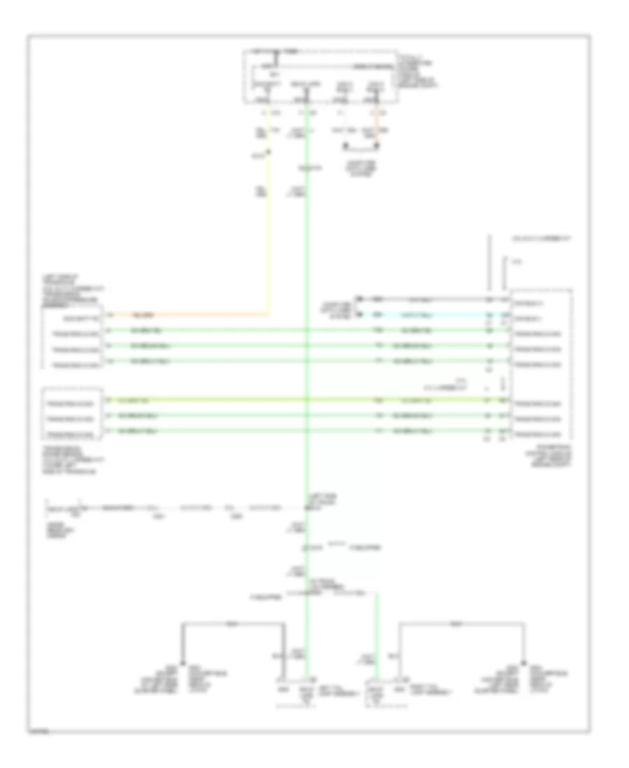
Backup Lamps Wiring Diagram for Dodge Avenger R/T 2010
List of elements for Backup Lamps Wiring Diagram for Dodge Avenger R/T 2010:
- (in trunk lid harness) s382
- (left side of transaxle) (3.5l & 2.7l 6 speed a/t) transmission solenoid/pressure assembly
- (left side of trunk) s315
- 2.4l
- 2.7l 4 speed a/t
- 3.5l & 2.7l 6 speed a/t
- B(+)
- Bkup lmps fd
- C10
- C104
- C200
- C201
- C319
- Can bus (+)
- Can bus (-)
- Can c bus (+)
- Can c bus (-)
- Circuit board
- Computer data lines system
- D64
- D65
- G303 (except convertible) (at left rear quarter panel)
- G303 (except convertible) (left rear quarter panel)
- G304 (convertible) (near decklid latch)
- Gnd
- Hot at all times
- If equipped
- Inside rearview mirror
- Left tail lamp assembly
- Nca
- Powertrain control module (left rear of engine compt)
- Right tail lamp assembly
- S172
- Swd batt fd
- T42
- Totally integrated power module (left side of engine compt)
- Trans rng c2 sig
- Trans rng c3 sig
- Trans rng c4 sig
- Transmission range sensor (2.4l & 2.7l 4 speed a/t) (lower left side of transaxle)
Exterior Lamps Wiring Diagram for Dodge Avenger R/T 2010
List of elements for Exterior Lamps Wiring Diagram for Dodge Avenger R/T 2010:
- (behind left rear fascia) s310
- (chrysler) s326
- (left kick panel)
- (left rear quarter panel)
- (left rear quarter panel) g303
- (near left low beam headlight) (dodge) s151
- (near right low beam headlight) (dodge) s152
- (right rear quarter panel) g305
- 2.4l 2.7l & 3.5l
- B(+)
- B15
- B16
- Backup lamps circuit
- Batt feed
- Bkup lmps fd
- Brk actv snse sig
- Brk actv snse sig2
- Brk actv snse sig2 c1
- C104
- C108
- C11
- C114
- C306
- C319
- Can bus (+)
- Can bus (-)
- Can bus(+)
- Can bus(+) nca
- Can bus(-)
- Can bus(-) nca
- Center high mounted stop lamp
- Center license lamp (dodge)
- Chrysler
- Circuit board
- Cluster
- Computer data lines system
- Convertible
- D54
- D55
- D64
- D65
- Dodge
- Eng ctrl run/strt ign
- Fd cmbd stp lmp
- Fuse 10a
- G102 (right shock tower)
- G105 (right shock tower)
- G250 (left side of center stack support)
- G302
- G303 (except (convertible)
- G303 (left rear quarter panel)
- G304 (convertible) (near decklid latch)
- G305 (right rear quarter panel)
- Gnd
- Hot at all times
- L217
- L53
- L55
- L60
- L61
- L62
- L63
- L70
- Left front lamp assembly
- Left license lamp (chrysler)
- Left tail lamp assembly
- Lin cnn
- Lower bank switch
- Lt ft trn sig fd
- Lt rr trn sig fd
- Nca
- Powertrain control module (left rear of engine compt)
- Prk/tl/lic/ run lmps 2
- Prk/tl/lic/ run lmps lt
- Prk/tl/lic/ run lmps rt
- Red
- Right front lamp assembly
- Right license lamp (chrysler)
- Right tail lamp assembly
- Rt ft trn sig fd
- Rt rr trn sig fd
- Run lmps 2 prk/tl/lic/ nca
- Run lmps lt prk/tl/lic/ nca
- Run strt ign eng ctrl/
- S110
- S120b
- S129
- S150
- S260 (near breakout to instrument cluster)
- S318 (convertble: left side of trunk) (except convertble: left side doorsill)
- S326 (chrysler)
- S390
- Stop lamp switch (top of brake pedal)
- Stp lmp fd cmbd
- Stp lmp fd rt
- Tail stp lmp rr fd
- Totally integrated power module (left side of engine compt)
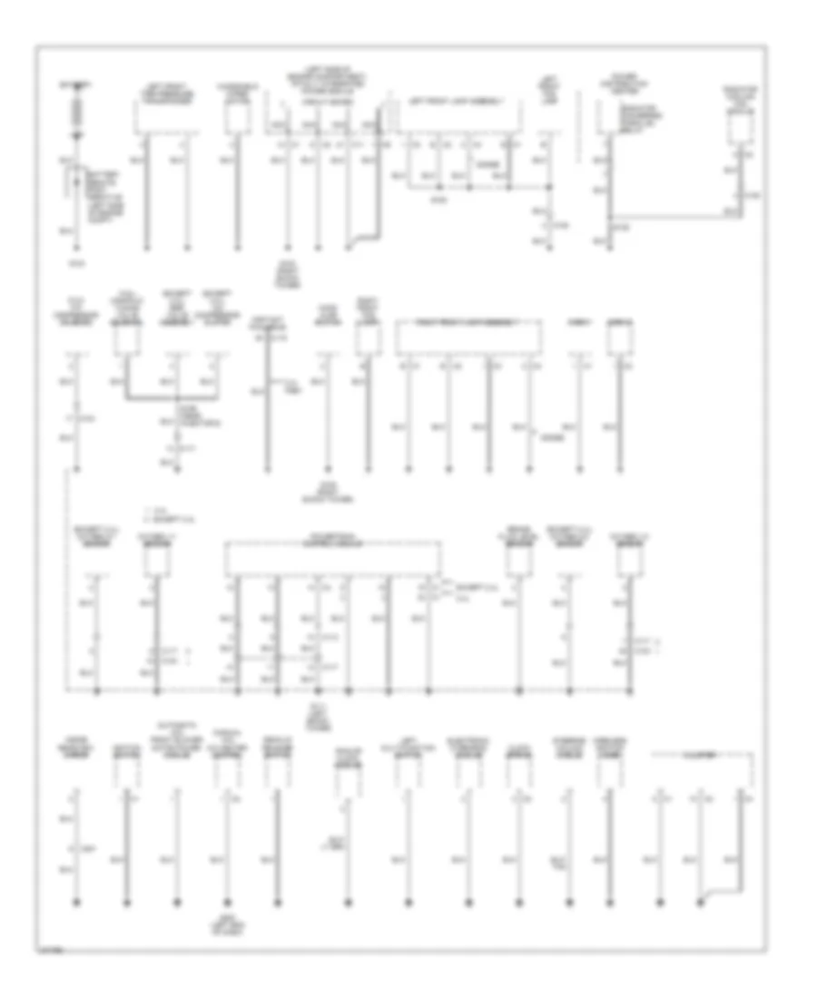
GROUND DISTRIBUTION
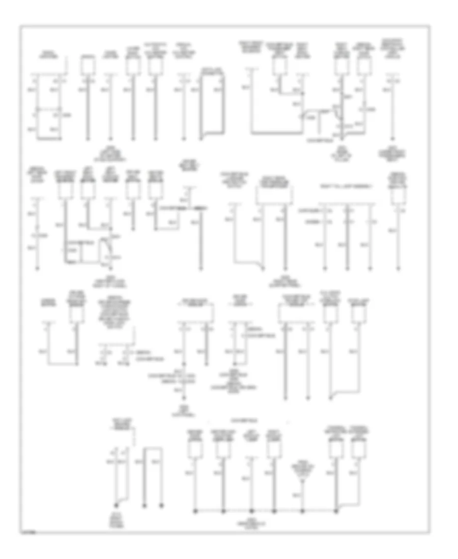
Ground Distribution Wiring Diagram (1 of 3) for Dodge Avenger R/T 2010
List of elements for Ground Distribution Wiring Diagram (1 of 3) for Dodge Avenger R/T 2010:
- (2.4l) a/c compressor solenoid
- (3.5l) manifold tuning valve solenoid
- (automatic a/c) front blower motor power module
- (except 2.4l) a/c compressor clutch
- (except 2.4l) egr valve assembly
- (except 2.4l) oxygen 2/1 sensor
- (except 2.4l) oxygen 2/2 sensor
- (info not available)
- (left side of engine compartment) totally integrated power module
- (manual a/c) a/c heater control
- 2.4l
- 2.4l pzev
- Analog clock module
- B c1
- B c2
- B1 c119
- Battery
- Brake fluid level sensor
- C1 b
- C103
- C105
- C108
- C11
- C113
- C117
- C2 a
- C2 b
- C201
- Circuit board
- Clock spring
- Cluster
- Decklid release switch
- Dodge
- Electronic overhead module
- Except 2.4l
- G102 (right shock tower)
- G103
- G105 (right shock tower)
- G111 (left shock tower)
- G200 (left end of dash)
- Hood ajar switch
- Horn 1
- Horn 2
- Ignition switch
- Inside rearview mirror
- Left front fog lamp
- Left front lamp assembly
- Left front tire pressure transponder
- Left multi-function switch
- Nca
- Oxygen 1/1 sensor
- Oxygen 1/2 sensor
- Power distribution center
- Powertrain control module
- Radiator cooling fan module
- Radiator fan-series/ parallel relay
- Right front fog lamp
- Right front lamp assembly
- S135
- S150
- S199 (near injector 6)
- Steering column module
- Windshield wiper motor
- Wireless ignition node
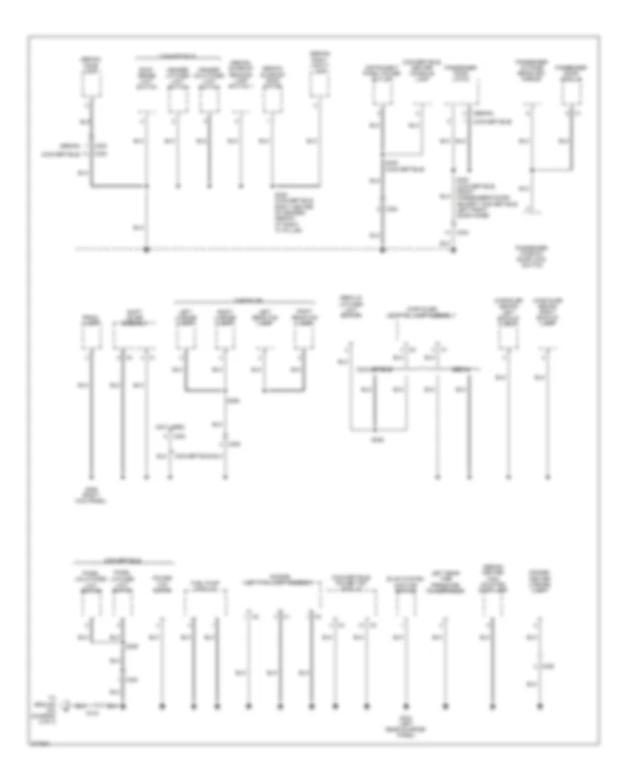
Ground Distribution Wiring Diagram (2 of 3) for Dodge Avenger R/T 2010
List of elements for Ground Distribution Wiring Diagram (2 of 3) for Dodge Avenger R/T 2010:
- (2.4l dohc) clutch interlock switch
- (automatic a/c) a/c heater control
- (chrysler) c2
- (convertible)
- (convertible) luggage protection switch
- (convertible) passenger seat switch
- (convertible) power top module
- (dodge)
- (manual a/c) a/c heater control
- (sedan)
- (sedan) driver express window/door lock switch (convertible) driver window/ door lock switch
- (sedan) electric heated backlite
- (sedan) left rear door latch
- (sedan) right rear door latch
- Anti-lock brakes module
- C206
- C214
- C302
- C308
- C309
- C312
- C325
- C326
- Center high mounted stop lamp
- Cigar lighter
- Convertible
- Data link connector
- Decked door latch
- Driver door latch
- Driver door module
- Driver outside rearview mirror
- Driver seat belt switch
- Driver seat switch
- From ground 304 (diagram 3 of 3)
- G110 (right shock tower)
- G250 (left side of center stack support)
- G300 (center floor, right of tunnel)
- G301 (base of left "b" pillar)
- G302 (left kick panel)
- G304 (near decklid hatch)
- G305 (right rear quarter panel)
- G307 (under front passenger's seat)
- Heated seats module
- Left backup lamp
- Left front headrest solenoid
- Left seat back heater
- Left seat cushion heater
- Lower bank switch
- Mirror switch
- Occupant restraint controller (orc) module
- Radio
- Radio amplifier
- Right backup lamp
- Right front headrest solenoid
- Right rear tire pressure transponder
- Right seat back heater
- Right seat cushion heater
- Right tail lamp assembly
- S001
- S331
- S359 (convertible) s369 (sedan) (convertible: driver's door)
- Sedan
- Stop lamp switch
- Tonneau extended limit switch
- Tonneau retracted limit switch
Ground Distribution Wiring Diagram (3 of 3) for Dodge Avenger R/T 2010
List of elements for Ground Distribution Wiring Diagram (3 of 3) for Dodge Avenger R/T 2010:
- (chrysler sedan) left backup lamp
- (chrysler sedan) right backup lamp
- (chrysler) left tail lamp assembly
- (convertible)
- (convertible) center console lamp
- (convertible) power top module
- (dodge) center license lamp
- (dodge) left tail lamp assembly
- (not used)
- (sedan)
- (sedan) center high mounted stop lamp
- (sedan) dome lamp
- (sedan) right vanity lamp
- (sedan) sunroof reading lamp switch 1
- (sedan) sunroof roof motor
- C300
- C303
- C305
- C306
- C319
- C320
- Chrysler
- Convertible
- Decklid latched limit switch
- Evap system monitor switch
- Fuel pump module
- G303 (left rear quarter panel)
- G306 (right kick panel)
- Header latched limit switch
- Header unlatched limit switch
- Instrument panel power outlet
- Left license lamp
- Left rear fog lamp
- Left rear tire pressure transponder
- Panel latched limit switch
- Panel unlatched limit switch
- Passenger door latch
- Passenger door module
- Passenger outside rearview mirror
- Passenger window/ door lock switch
- Power top motor
- Prndl lamp
- Right license lamp
- Right rear fog lamp
- Roof sense limit switch
- S326
- S339 (convertible)
- S349 (convertible: right center of header) (sedan: at right "a" pillar)
- S353 (convertible: front passenger's door) (except convertible: left front door hinge)
- S389
- S390
- Sedan
- Shift lever assembly
- To ground (diagram 2 of 3)
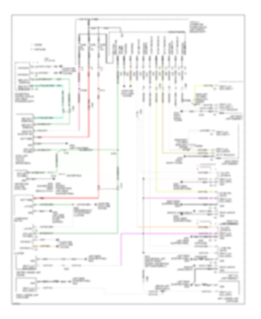
HEADLIGHTS
Headlights Wiring Diagram for Dodge Avenger R/T 2010
List of elements for Headlights Wiring Diagram for Dodge Avenger R/T 2010:
- (near breakout to instrument cluster)
- (near left low beam headlight) (dodge) s151
- (near right low beam headlight) (dodge) s152
- (not used)
- Auto hdlp sig
- Auto hdlp sig snsr sunld rtn can b bus (-) can b bus (+)
- B (+)
- Batt feed
- C108
- C11
- C114
- C200
- C306
- Can b bus (+)
- Can b bus (-)
- Circuit board
- Cluster
- Computer data lines system
- D54
- D55
- Eng ctrl
- Eng ctrl run/strt ign
- Fog lamp rly ctrl rr
- Fog lamp/ind fd 1
- Fog lamp/ind fd 2
- Fuse 10a
- Fuse 10a nca
- G102 (right shock tower)
- G105 (right shock tower)
- G200 (left end of dash)
- G250 (left side of center stack support)
- G303 (left rear quarter panel)
- Gnd
- Hot at all times
- Hot at all times nca
- Hvac a/c heater control
- Iod fd
- L33
- L34
- L43
- L44
- L60
- L61
- L70
- L89
- L90
- Left front assembly lamp
- Left front fog lamp
- Left front turn sig fd
- Left high beam fd
- Left low beam fd
- Left multi-function switch
- Left rear fog lamp
- Lin ccn
- Lower bank switch
- Lt ft trn sig fd
- Lt hi beam fd
- Lt lo beam fd
- Nca
- Park brk sw sig
- Park brk sw sns
- Parking brake switch (base of parking brake lever)
- Prk/tl/lic/run lmps lt
- Prk/tl/lic/run lmps rt
- Red
- Right front assembly lamp
- Right front fog lamp
- Right front turn sig fd
- Right high beam fd
- Right low beam fd
- Right rear fog lamp
- Rt ft trn sig fd
- Rt hi beam fd
- Rt lo beam fd
- Run/start ign
- S110
- S150
- S210
- S222
- S260
- S371
- S390
- Snsr sunld rtn
- Sun sensor
- Totally integrated power module (left side of engine compt)
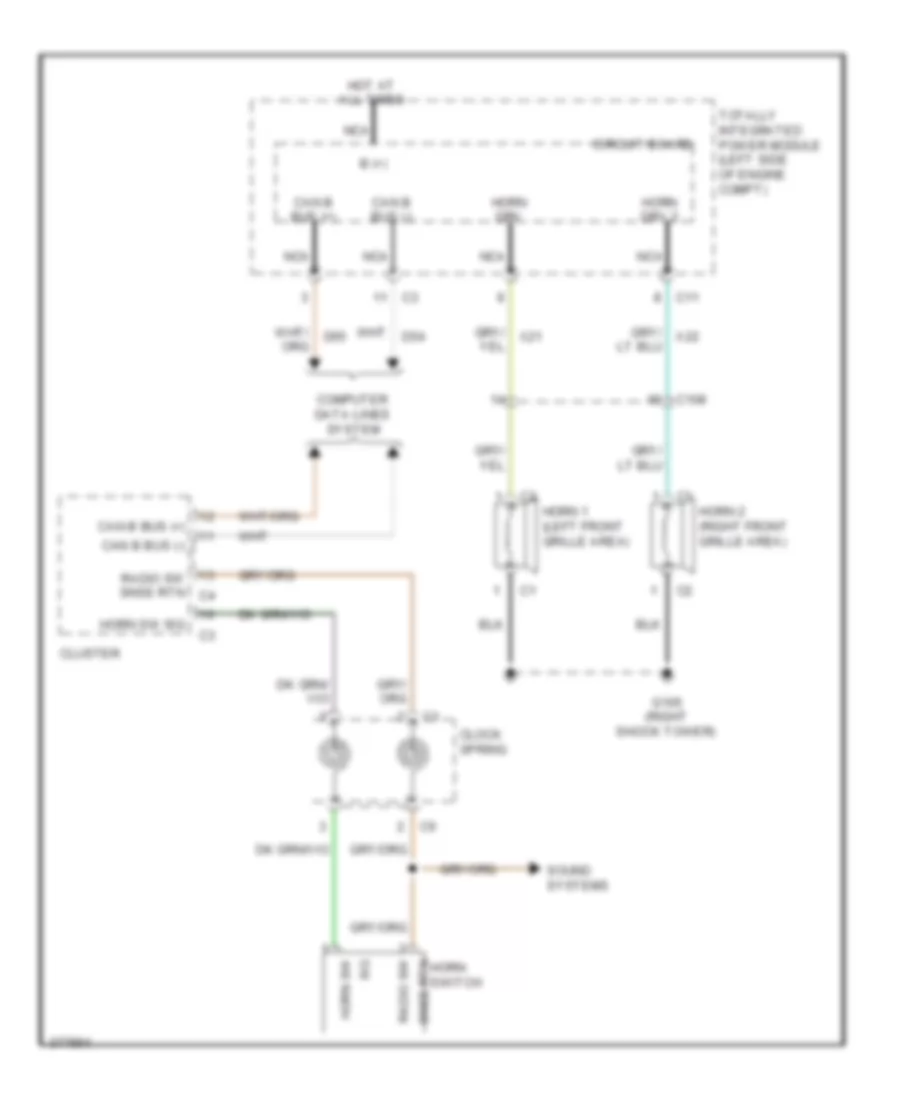
HORN
Horn Wiring Diagram for Dodge Avenger R/T 2010
List of elements for Horn Wiring Diagram for Dodge Avenger R/T 2010:
- B (+)
- C108
- C11
- Can b bus (+)
- Can b bus (-)
- Circuit board
- Clock spring
- Cluster
- Computer data lines system
- G105 (right shock tower)
- Horn 1 (left front grille area)
- Horn 2 (right front grille area)
- Horn drv
- Horn drv 2
- Horn sw
- Horn sw sig
- Hot at all times
- Nca
- Radio sw
- Radio sw snse rtn c4
- Sig
- Snse rtn horn switch
- Sound systems
- Totally integrated power module (left side of engine compt)
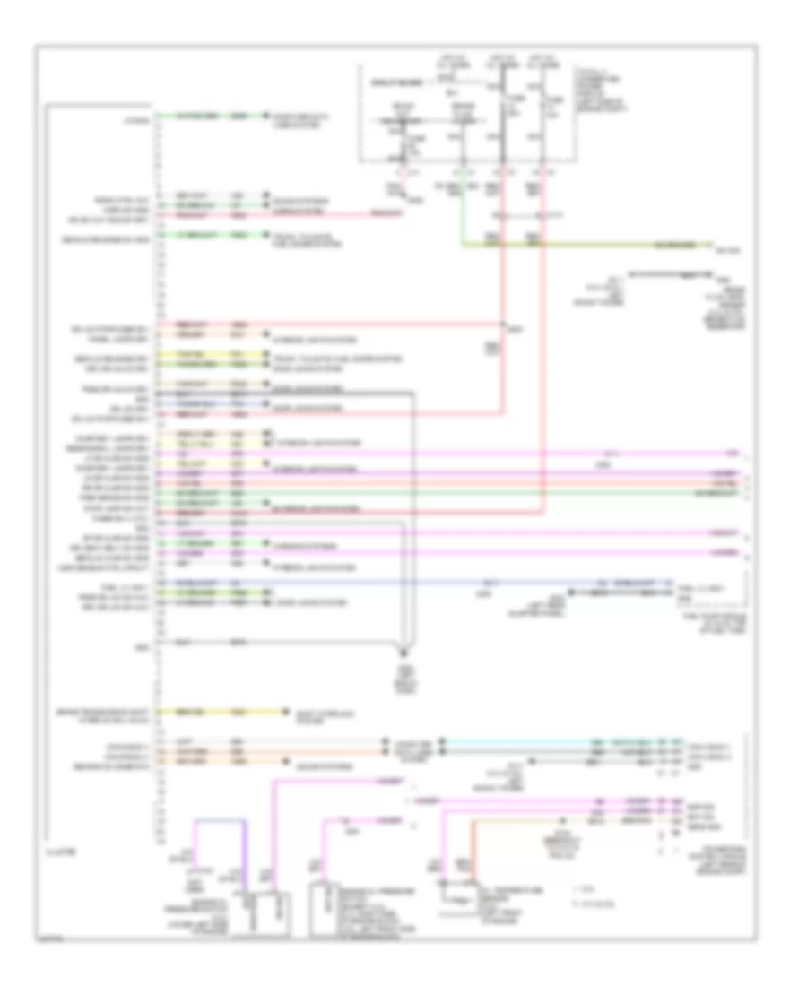
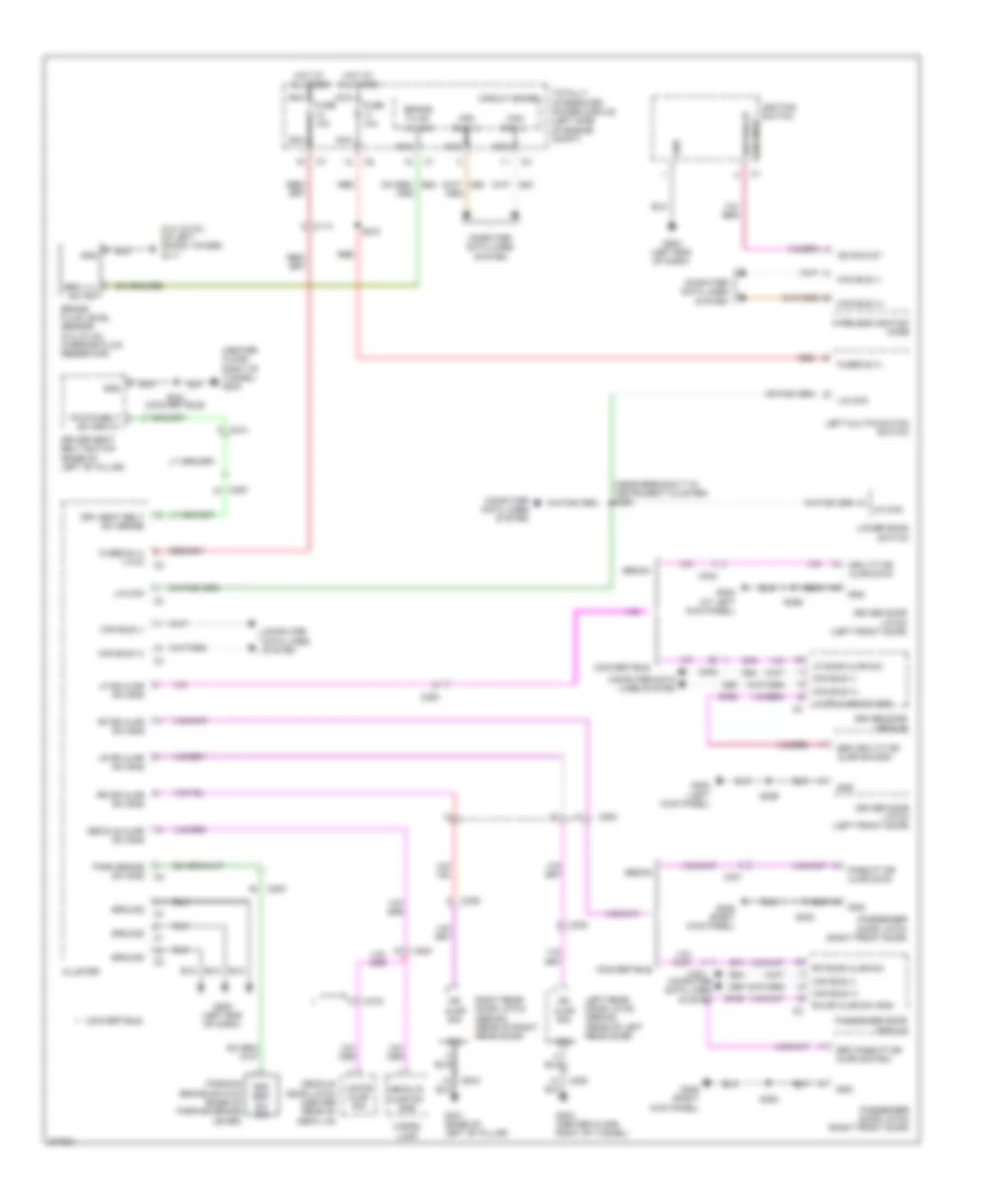
INSTRUMENT CLUSTER
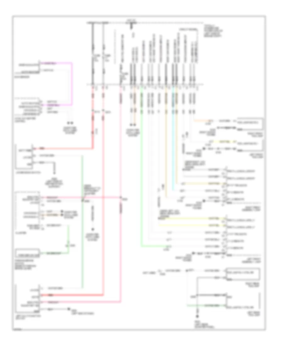
Instrument Cluster Wiring Diagram (1 of 2) for Dodge Avenger R/T 2010
List of elements for Instrument Cluster Wiring Diagram (1 of 2) for Dodge Avenger R/T 2010:
- (not used)
- 2.4l
- 2.7l & 3.5l
- A412
- A932
- B(+)
- B25
- Brake fluid level sensor (2.4l & 3.5l: brake fluid reservoir)
- Brake fluid lvl sig
- Brake transmission shift interlck sol unlck
- Breather
- C103
- C11
- C114
- C200
- C201
- Can b bus (+)
- Can b bus (-)
- Can c bus (+)
- Can c bus (-)
- Circuit board
- Cluster
- Computer data lines system
- Courtesy lamps drv
- D506
- D54
- D55
- D64
- D65
- Decklid ajar sw sns
- Decklid release drv
- Decklid release sw sns
- Door locks system
- Dr lck drv
- Dr lck pwr-fused b(+)
- Drv dr lck sw mux
- Drv dr unlck drv
- Drv seat belt sw sns
- E12
- Engine oil pressure switch (2.4l) (lower left side of engine)
- Engine oil pressure switch (except 2.4l) (2.7l: right side of engine block) (3.5l: left front side of engine block)
- Eop
- Eop sig
- Eot sig
- Exterior lights system
- F202
- Fuel lvl sig 1
- Fuel pump module (c1 & c2: top of fuel tank)
- Fuse 10a
- Fuse 20a
- Fused b(+) (i.o.d.)
- G111 (2.4l & 3.5l: left shock tower)
- G200 (left end of dash)
- G24
- G303 (left rear quarter panel)
- G38
- G74
- G75
- G76
- G77
- G78
- Gnd
- Horn sw sns
- Horns system
- Hot at all times
- Ign sw out (run-start)
- Interior lights system
- K321
- K915
- L53
- Lf dr ajar sw sns
- Lin bus
- Lr dr ajar sw sns
- M24
- M25
- M27
- Nca
- Oil temperature sensor (2.4l) (left front of engine)
- P223
- P238
- P240
- P31
- P33
- P696
- P697
- Panel lamps drv
- Park brake sw sns
- Pass dr lck sw mux
- Pass dr unlck drv
- Powertrain control module (left rear of engine compt)
- R57
- Radio ctrl mux
- Reading/rail lamps drv
- Rem rad sw snse rtn
- Rf dr ajar sw sns
- Rr dr ajar sw sns
- S184 (breakout to c101 & pcm c2)
- S200
- S222
- Sens gnd
- Shift interlock system
- Sound systems
- Stop lamp sw out
- Sw sig
- Totally integrated power module (left side of engine compt)
- Trunk, tailgate, fuel doors system
- Ugdo enable ctrl circuit
- Warning systems
- X20
- X920
- Z910
- Z916
- Z931
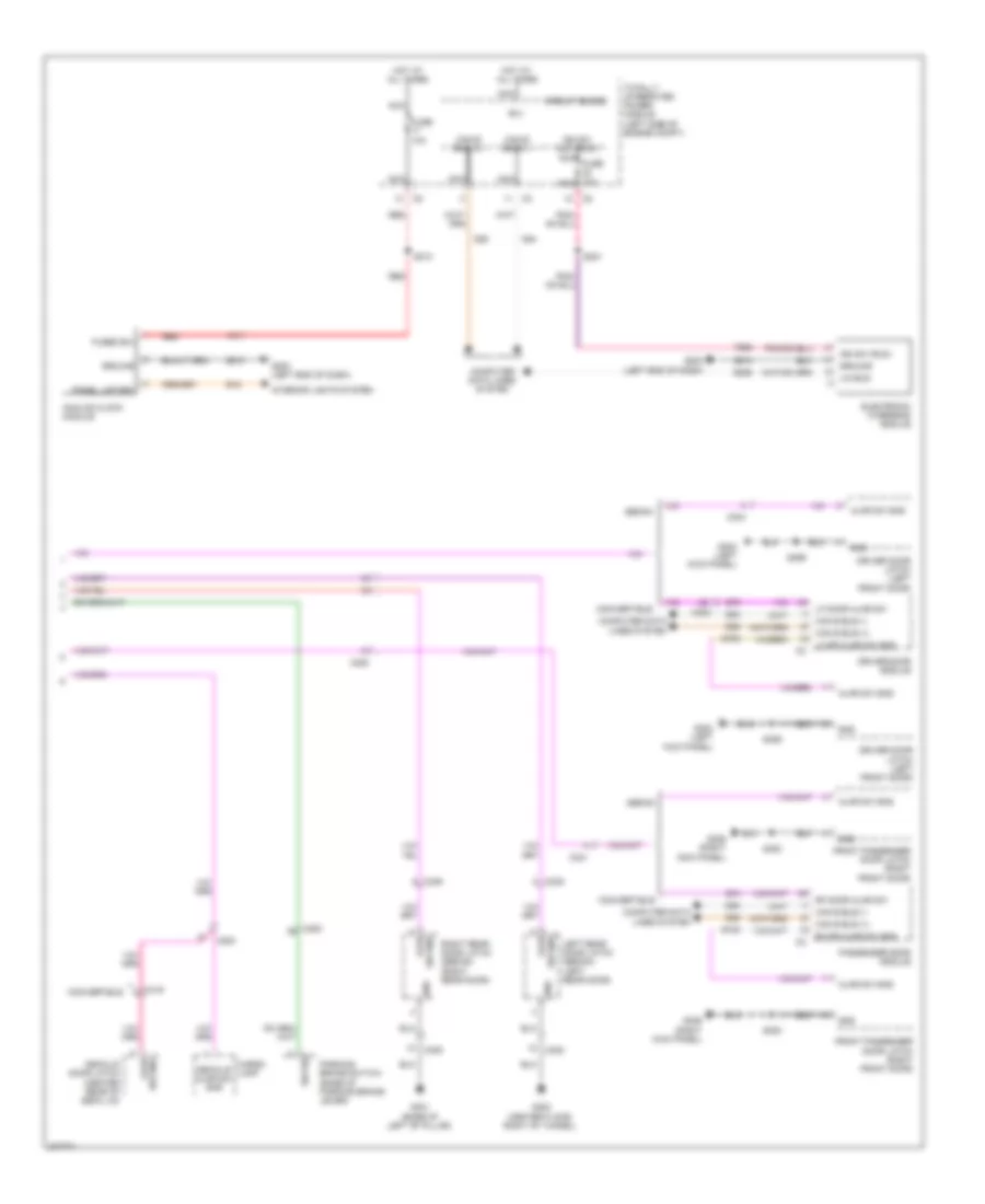
Instrument Cluster Wiring Diagram (2 of 2) for Dodge Avenger R/T 2010
List of elements for Instrument Cluster Wiring Diagram (2 of 2) for Dodge Avenger R/T 2010:
- A411
- Ajar
- Ajar sw sns
- Analog clock module
- B(+)
- C200
- C301
- C302
- C304
- C308
- C309
- C319
- Can b bus (+)
- Can b bus (-)
- Cargo lamp
- Circuit board
- Computer data lines system
- Convertible
- D506
- D54
- D55
- Decklid ajar sw sns
- Decklid door latch (center rear of deck lid)
- Driver door latch (left front door)
- Driver door module
- E12
- Electronic overhead module
- F929
- Front passenger door latch (right front door)
- Fuse 10a
- Fused b(+)
- G200 (left end of dash)
- G300 (center floor, right of tunnel)
- G301 (base of left "b" pillar)
- G302 (left kick panel)
- G306 (right kick panel)
- G74
- G745
- G75
- G755
- Gnd
- Ground
- Hot at all times
- Ign sw (run)
- Ign sw out (run)
- Interior lights system
- Left rear door latch (sedan) (left rear door)
- Lf door ajar sw
- Lh dr ajar sw sns
- Lin bus
- Nca
- Nca fuse 10a nca
- Panel lmp drv
- Parking brake switch (base of parking brake lever)
- Passenger door module
- Red
- Rf door ajar sw
- Rh dr ajar sw sns
- Right rear door latch (sedan) (right rear door)
- S210
- S221
- S353
- S359
- S369
- Sedan
- Sw sig
- Sw sns
- Sw sns ajar
- Totally integrated power module (left side of engine compt)
- Z910
INTERIOR LIGHTS
Interior Lights Wiring Diagram (1 of 2) for Dodge Avenger R/T 2010
List of elements for Interior Lights Wiring Diagram (1 of 2) for Dodge Avenger R/T 2010:
- (behind left end of dash) s204
- (right kick panel) g306
- Analog clock module
- B(+)
- C11
- C111
- C114
- C200
- C300
- C305
- Can bus (+)
- Can bus (-)
- Circuit board
- Cluster
- Computer data lines system
- Dim 3 ip
- Dim 31p
- Driv ft dr ajar sw in
- E12
- Egn ctrl run/start ign
- Eng ctrl run/strt ign
- Except convertible
- Ft hdr crsty fd
- Fuse 10a
- G200 (left end of dash)
- Ground
- Hot at all times
- Iod fd
- Left multi-function switch
- Lgate ajar sig
- Lin ccn
- Lower bank switch
- Lr door ajar sw sig
- Nca
- Pass ft dr ajar sw in
- Power top switch (convertible)
- Prndl lamp
- Reading/rail lamps drv
- Rr door ajar sw sig
- S222
- S260 (left side of dash, in instrument panel harness)
- Totally integrated power module (left side of engine compt)
- Trank lmp fd
- Ugdo disable
- Z910
Interior Lights Wiring Diagram (2 of 2) for Dodge Avenger R/T 2010
List of elements for Interior Lights Wiring Diagram (2 of 2) for Dodge Avenger R/T 2010:
- (base of left "b" pillar) g301
- (center floor, right of tunnel) g300
- (convertible) s359 (except convertible) s369
- (left kick panel) g302
- (not used)
- (right "a" pillar) s342
- (right "a" pillar) s343
- (right kick panel) g306
- C200
- C201
- C300
- C301
- C304
- C305
- C308
- C309
- C319
- Can bus (+)
- Can bus (-)
- Cargo lamp
- Center console lamp
- Computer data lines system
- Convertible
- D54
- D55
- Decklid door latch (center rear of deck lid)
- Dome lamp
- Dr ajar switch
- Driv ft dr ajar sw in
- Driver door latch (left front door)
- Driver door module
- Except
- Except convertible
- Fd hdr crtsy fd
- Ft hdr crtsy fd
- G304 (near decklid latch)
- G306 (right kick panel)
- G745
- G755
- Gnd
- Inside rearview mirror
- Iod fd
- Left rear door latch (except convertible) (left rear door)
- Left vanity lamp
- Lgate ajar sig
- Lt rr dr ajar sig
- Pass ft dr ajar sw in
- Passenger door latch (right front door)
- Passenger door module
- Passenger's air bag)
- Rail lmp fds
- Reading/ sunroof switch lamp
- Right rear door latch (except convertible) (right rear door)
- Right vanity lamp
- Rt rr dr ajar sig
- S206 (behind
- S207 (behind
- S339
- S349
- S353
- Trank lmp fd
- Ugdo disable
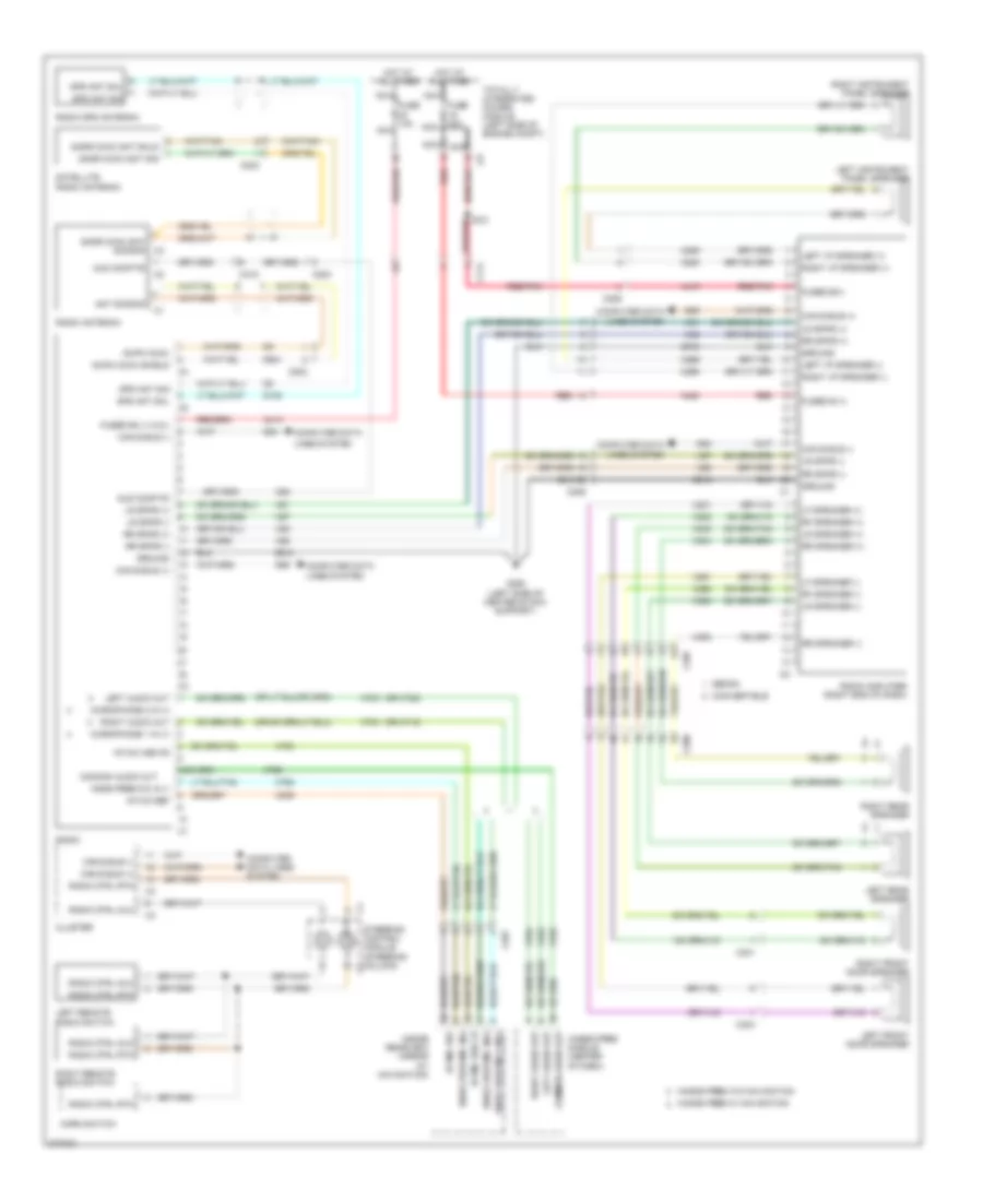
NAVIGATION
Navigation Wiring Diagram for Dodge Avenger R/T 2010
List of elements for Navigation Wiring Diagram for Dodge Avenger R/T 2010:
- (or x712)
- (or x722)
- A413
- A419
- A420
- Am/fm coax
- Am/fm coax shield
- Ant sig/shd
- Aud comp fd
- C114
- C200
- C201
- C202
- C203
- C206
- C207
- C301
- C304
- C319
- Can b bus (+)
- Can b bus (-)
- Cluster
- Common audio out
- Computer data
- Computer data lines system
- Convertible
- D108
- D54
- D55
- D931
- Fuse 10a nca
- Fuse 20a nca
- Fused b (+)
- Fused b(+)
- Fused b(+) (i.o.d.)
- G250 (left side of center stack support)
- Gps ant shl
- Gps ant sig
- Ground
- Hands free module (center of dash)
- Hands free w/ navigation
- Hands free w/o navigation
- Hf mic hsd fd
- Hf mic ref
- Hnds free mic in (-)
- Hnds free mic in(+)
- Hnds free mic in(-)
- Hnds free mic2 in(+)
- Horn switch
- Hot at all times
- Inside rearview mirror (w/ navigation)
- Left audio out
- Left front door speaker
- Left i/p speaker (+)
- Left i/p speaker (-)
- Left instrument panel speaker
- Left rear speaker
- Left remote radio switch
- Lf speaker (+)
- Lf speaker (-)
- Lines system
- Lr speaker (+)
- Lr speaker (-)
- Lr spkr (+)
- Lr spkr (-)
- Microphone 1 in (+)
- Microphone 2 in (+)
- Nca
- Radio
- Radio amplifier (right end of dash)
- Radio antenna
- Radio ctrl mux
- Radio ctrl rtn
- Radio gps antenna
- Red
- Red/pnk
- Rf speaker (+)
- Rf speaker (-)
- Right audio out
- Right front door speaker
- Right i/p speaker (+)
- Right i/p speaker (-)
- Right instrument panel speaker
- Right rear speaker
- Right remote radio switch
- Rr speaker (+)
- Rr speaker (-)
- Rr spkr (+)
- Rr spkr (-)
- S121 red/pnk
- Sadr coax sat shld
- Sadr coax sat sig
- Sadr coax sat sig/shd
- Satellite radio antenna
- Sedan
- Steering control module (steering column) c6
- Totally integrated power module (left side of engine compt)
- X201
- X202
- X208
- X209
- X291
- X292
- X298
- X299
- X303
- X304
- X393
- X394
- X51
- X52
- X57
- X58
- X62
- X703
- X704
- X792
- X793
- X795
- X835
- Z912
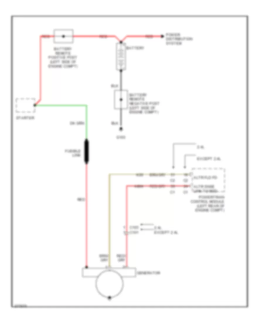
POWER DISTRIBUTION
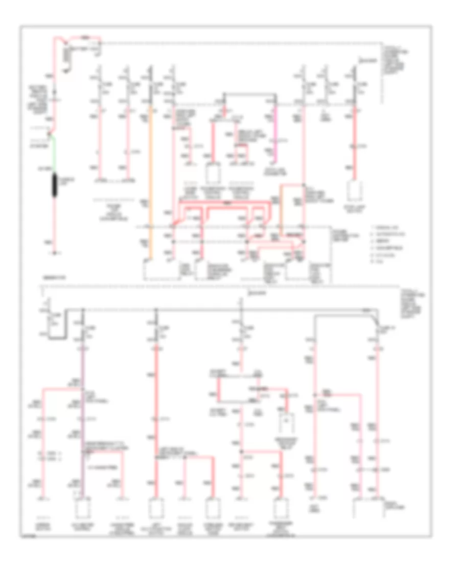
Power Distribution Wiring Diagram (1 of 3) for Dodge Avenger R/T 2010
List of elements for Power Distribution Wiring Diagram (1 of 3) for Dodge Avenger R/T 2010:
- (below left shock tower grounds) s114
- (forward from left shock tower) s110
- (left end of instrument panel) s210
- (near breakout to instrument cluster) s212
- (not used)
- 2.4l
- 2.4l pzev
- 2.7l & 3.5l
- 2.7l & 3.5l
- A/c heater control
- Analog clock module
- Asd/ main relay
- Automatic a/c
- Battery
- Battery remote positive post (left side of engine compt)
- Bus bar
- C104
- C11
- C114
- C119
- C206
- C214
- C300
- C302
- C312
- Convertible
- Data link connector
- Driver seat switch
- Except 2.4l pzev
- Fuse 10a
- Fuse 19 20a
- Fuse 20a
- Fuse 25a
- Fuse 30a
- Fuse 40a
- Fusible link
- Generator
- Hands free module (if equipped)
- Kick panel)
- Left multi-function switch
- Lower bank switch
- Manual a/c
- Mirror switch
- Nca
- Passenger seat switch (convertible)
- Power distribution center
- Power top module (convertible)
- Powertrain control module
- Radiator fan- low/ high relay
- Radiator fan- medium/ high relay
- Radiator fan-series/ parallel relay
- Radio amplifier
- Red
- Red/ pnk
- S112
- S121 (left red/ pnk
- S134
- Secondary air pump relay
- Sedan
- Starter
- Stop lamp switch
- Totally integrated power module (left side of engine compt)
- W/ hands free
- Wireless ignition node
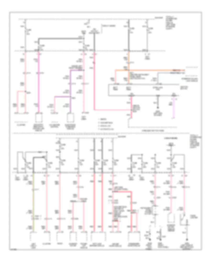
Power Distribution Wiring Diagram (2 of 3) for Dodge Avenger R/T 2010
List of elements for Power Distribution Wiring Diagram (2 of 3) for Dodge Avenger R/T 2010:
- (above ignition switch) s220
- (convertible: center of right door module) red
- (inside left front fender) s124
- (left end of dash panel) s312
- (not used)
- (sedan: driver's door) s359 s352
- A/c heater control
- Anti-lock brakes module
- Automatic a/c
- B(+)
- Batt feed
- Bus bar
- C104
- C11
- C111
- C114
- C300
- C302
- C303
- C305
- Cigar lighter
- Circuit board
- Cluster
- Conver- tible
- Convertible
- Driver door module
- Electronic overhead module
- Fuse 10a
- Fuse 10a nca
- Fuse 15a
- Fuse 20a
- Fuse 30a
- Fuse 40a
- G200 (left end of dash)
- G250 (left side of center stack support)
- G306 (right kick panel)
- Gnd
- Ign r pre
- Ign r pre 3
- Ign run st
- Ign sw out (run-start)
- Ignition switch
- Instrument panel power outlet
- Left vanity lamp
- Manual a/c
- Nca
- Occupant restraint controller module
- Passenger door module
- Pnk
- Power top module
- Radio
- Red
- Red/ tan
- Red/tan
- S200
- S211 (center instrument panel near ignition switch)
- S221
- S339
- S371
- S603 red
- Sedan
- Steering column lock module
- Strg lock mod
- Sunroof motor
- Sunroof motor/ module (sedan)
- Sw sens
- Totally integrated power module (left side of engine compt)
- Wireless ignition node
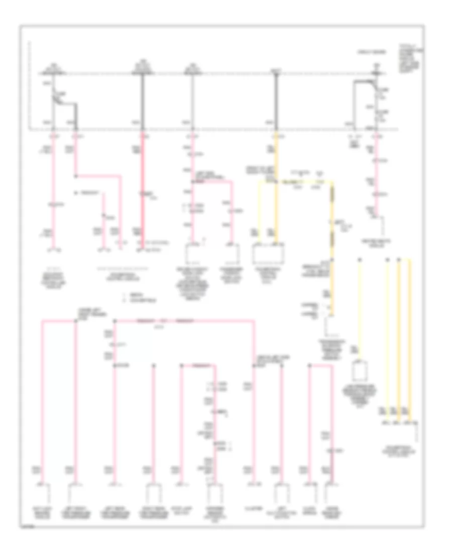
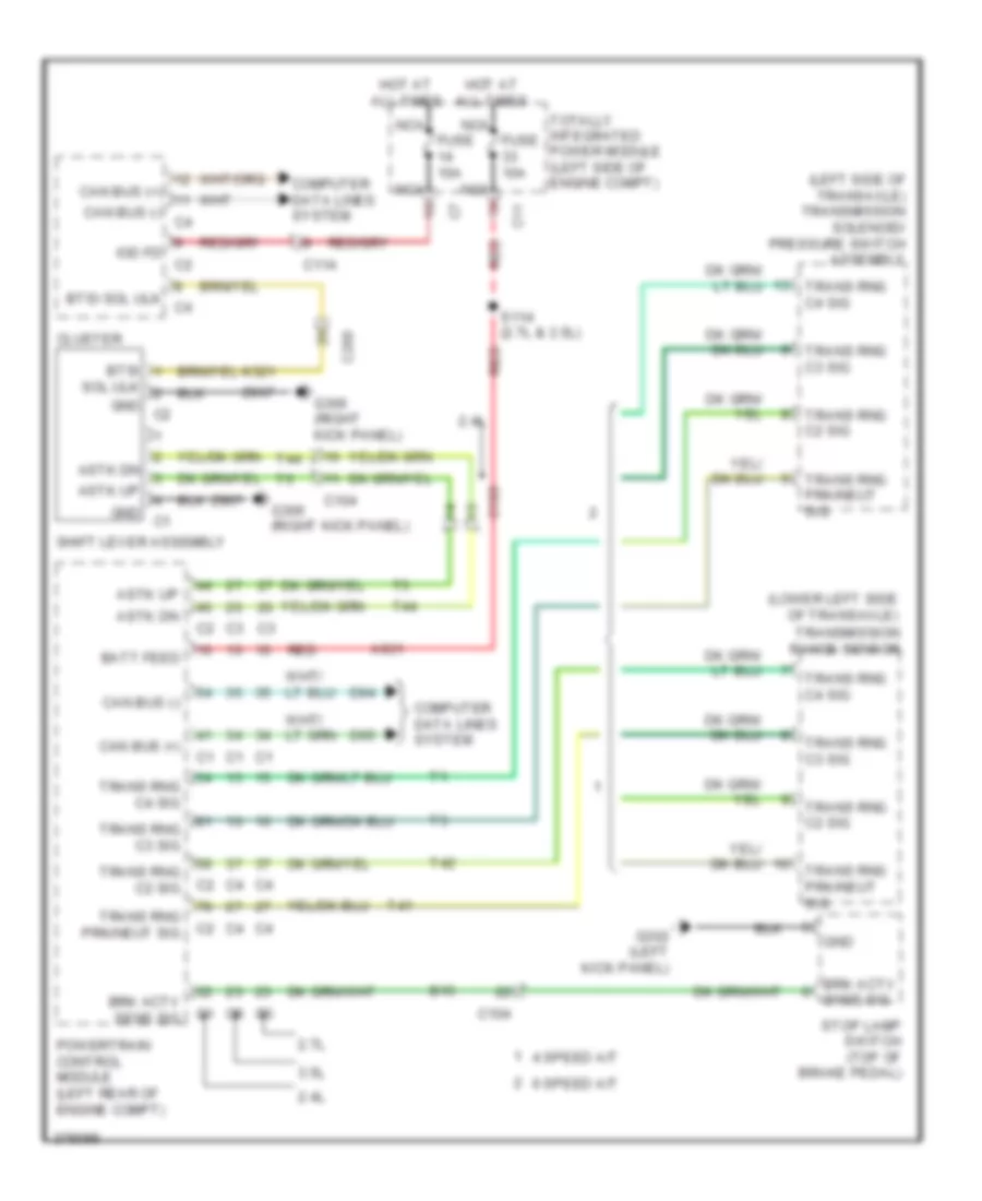
Power Distribution Wiring Diagram (3 of 3) for Dodge Avenger R/T 2010
List of elements for Power Distribution Wiring Diagram (3 of 3) for Dodge Avenger R/T 2010:
- (2.4l)
- (2.7l/3.5l)
- (above left side of glove box) s222
- (front of left shock tower) (2.4l) s127
- (inside left front fender) s126
- (left end of dash panel) s323
- (not used)
- 2.4l
- 2.7l & 3.5l
- 4-speed/ a/t
- 6-speed/ a/t
- Anti-lock brakes module
- Batt fd
- C10
- C101
- C103
- C104
- C11
- C111
- C113
- C114
- C201
- C214
- C302
- C303
- C305
- C315
- Circuit board
- Clock spring
- Cluster
- Convertible
- Driver window/ door lock switch (convertible) driver express window/door lock switch (sedan)
- Fuse 10a
- Heated seats module
- Ign r pre 2
- Ign sw out (run-acc)
- Ign sw out (run-start)
- Ign sw out (unlock- run-start)
- Infrared sensor (automatic a/c)
- Inside rearview mirror
- Left front tire pressure transponder
- Left multi-function switch
- Left rear tire pressure transponder
- Line pressure sensor/variable force solenoid assembly (4-speed a/t)
- Nca
- Occupant restraint controller module
- Passenger window/ door lock switch
- Pnk
- Pnk/ red
- Powertrain control module
- Powertrain control module (2.7l & 3.5l)
- Right rear tire pressure transponder
- S120b
- S153
- S172 (breakout to c106, above transmission)
- S348
- S355
- Sedan
- Stop lamp switch
- Totally integrated power module (left side of engine compt)
- Transmission solenoid/ pressure switch assembly
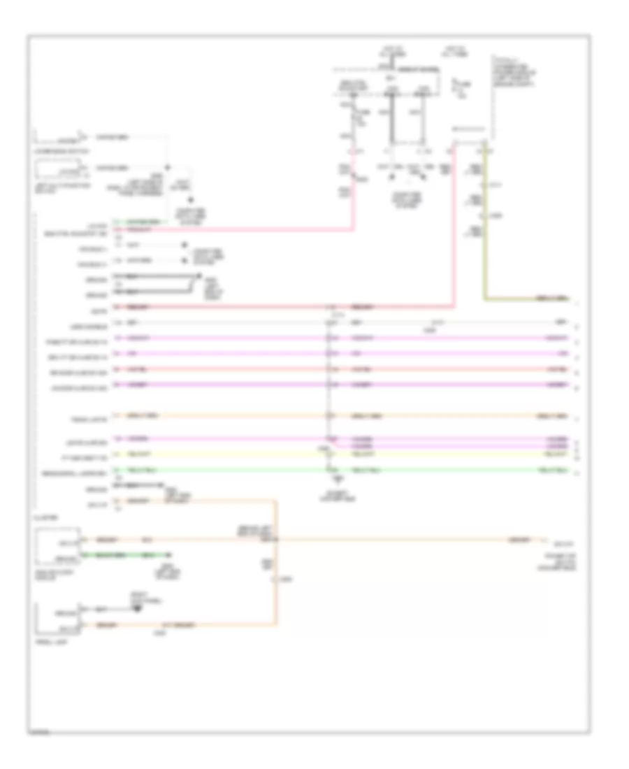
POWER DOOR LOCKS
Power Door Locks Wiring Diagram (1 of 2) for Dodge Avenger R/T 2010
List of elements for Power Door Locks Wiring Diagram (1 of 2) for Dodge Avenger R/T 2010:
- (center instrument panel near ignition switch)
- (left end of dash) g200
- (left kick panel)
- A937
- A952
- B(+)
- Batt feed
- C11
- C114
- C200
- C301
- C302
- C304
- Can bus (+)
- Can bus (-)
- Circuit board
- Cluster
- Computer data lines system
- D508
- D54
- D55
- Dckld/liftgte rel sw sig
- Dr ajar lt rr sig
- Dr ajar rt rr sig
- Dr lck mtr unlck pos driv
- Dr lck mtr unlck pos pass
- Dr lck mtr unlock pos driv
- Dr lk mtr b+ lk
- Dr lk mux driv
- Dr lk mux pass
- Dr lt mtr b+ lk
- Driv ft dr ajar sw in
- Driver door latch (left front door)
- Driver door module
- F20
- F892
- G200 (left end of dash)
- G302
- G302 (left kick panel)
- G306 (right kick panel)
- Gnd
- Headlights system
- Horn drv
- Horn drv 2
- Horns system
- Hot at all times
- Ign run st
- Ign run st sw snse
- Ignition switch
- Iod fd
- L33
- L34
- L43
- L44
- Lgate ajar sig
- Lgate pwr rel
- Lin tire press
- Lt hi beam fd
- Lt lo beam fd
- Nca
- Pass ft dr ajar sw in
- Passenger door latch (right front door)
- Pnk
- Q15
- Red
- Red/tan
- Rt hi beam fd
- Rt lo beam fd
- S211
- S220
- S261
- S353
- S359
- S369
- Securty fd to strg lk mod
- Steering column lock module (steering column)
- Sw pwr wdw lk out fd
- Totally integrated power module (left side of engine compt)
- Unlck pos pass dr lck mtr
- Warning systems
- Wireless ignition node
- X21
- X22
- Z908
- Z910
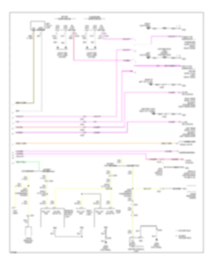
Power Door Locks Wiring Diagram (2 of 2) for Dodge Avenger R/T 2010
List of elements for Power Door Locks Wiring Diagram (2 of 2) for Dodge Avenger R/T 2010:
- (center of left door module) s351
- (near right kick panel) s303
- A937
- Ajar sig lgate
- B+ lk dr lt mtr
- Batt feed
- C104
- C108
- C11
- C114
- C200
- C301
- C302
- C303
- C304
- C308
- C309
- Can bus (+)
- Can bus (-)
- Cargo lamp
- Circuit board
- Computer data lines system
- D54
- D55
- Decklid door latch (center rear of deck lid)
- Decklid release switch
- Dr ajar lt rr sig
- Dr ajar rt rr sig
- Dr lck mtr unlck pos pass
- Dr lk mux driv
- Dr lk mux pass
- Dr lt mtr b+ lk
- Driver express window/door lock switch
- Fuse 10a
- Fuse 20a
- Fuse 30a
- G105 (right shock tower)
- G200 (left end of dash)
- G300 (center floor, right of tunnel)
- G301 (base of left "b" pillar)
- G302 (left kick panel)
- G304 (near decklid latch)
- G306 (right kick panel)
- G70
- Gnd
- Hood ajar switch (right front of engine compt)
- Hot at all times
- Left rear door latch (left rear door)
- Left rear power window switch
- Lgate ajar sig
- Lgate pwr rel
- Nca
- Passenger door module
- Passenger window/ door lock switch
- Red
- Red/tan
- Right rear door latch (left rear door)
- Right rear power window switch
- S200
- S210
- S312
- S353
- S369
- S371
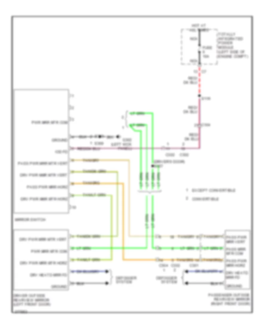
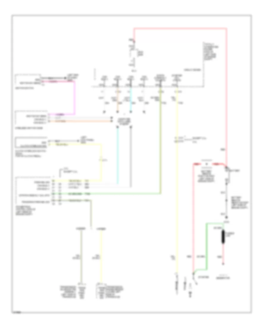
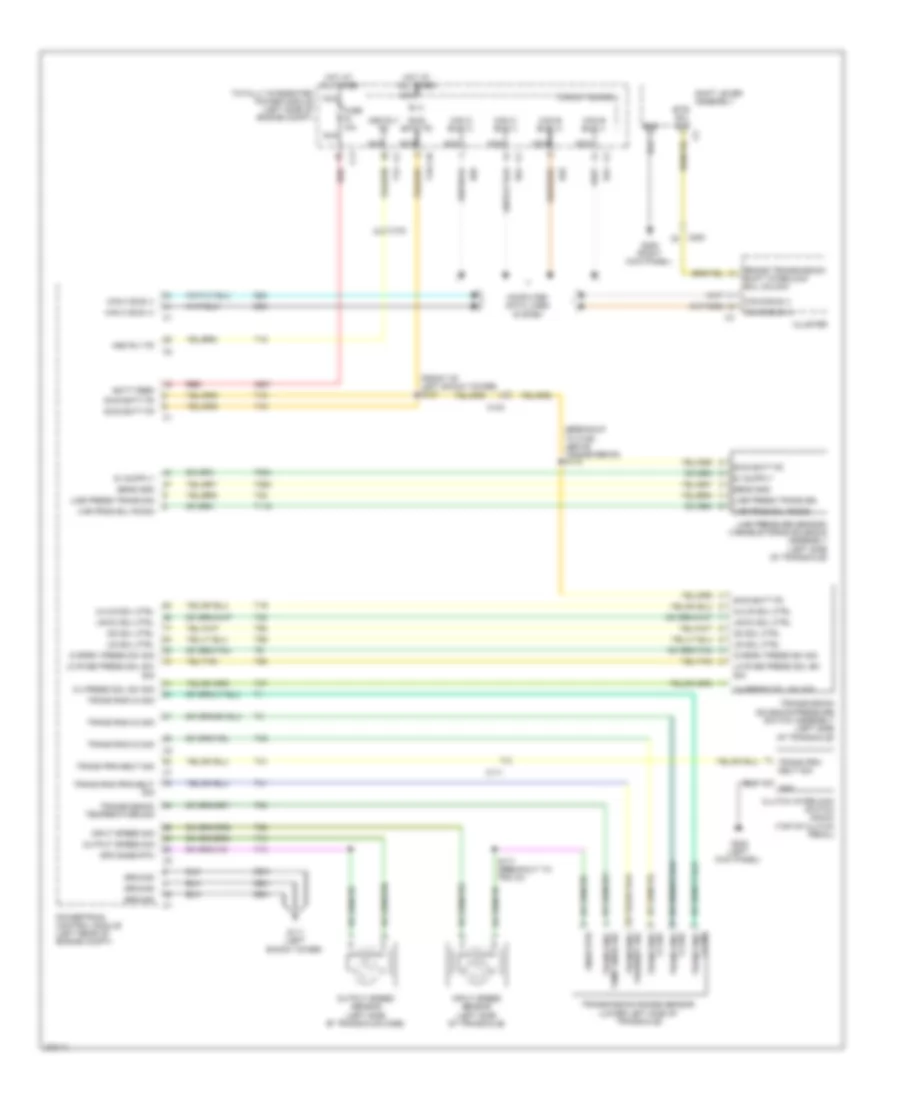
- Sw pwr wdw lk out fd
- Sw sig
- Totally integrated power module (left side of engine compt)
- Uhood sw sig
- Unlck pos pass dr lck mtr
- Z908
POWER MIRRORS
Automatic Day/Night Mirror Wiring Diagram for Dodge Avenger R/T 2010
List of elements for Automatic Day/Night Mirror Wiring Diagram for Dodge Avenger R/T 2010:
- (behind passenger's air bag) s206
- (left end of dash) g200
- Bkup lmps fd
- C11
- C114
- C201
- Cluster
- Convertible
- Exterior lights system
- F202
- Fd hdr crtsy fd eng ctrl
- Ft hdr crtsy fd c2
- Fuse 10a
- G200 (left end of dash)
- Gnd
- Hands free mic in +
- Hands free mic in -
- Hf mic 2 in +
- Hf mic hsd fd
- Hf mic ref
- Hot at all times
- Hot w/ run/start relay energized
- Inside rearview mirror
- Interior lights system
- M24
- M27
- Nca
- Radio
- Rail lamp fds
- Rail lmp fds
- Run/strt ing
- S207
- S222
- Totally integrated power module (left side of engine compt)
- X712
- X722
- X792
- X793
- X835
- Z910
Power Mirrors Wiring Diagram for Dodge Avenger R/T 2010
List of elements for Power Mirrors Wiring Diagram for Dodge Avenger R/T 2010:
- (driver's door) s357
- C104
- C301
- C302
- C304
- Convertible
- Defogger system
- Driver outside rearview mirror (left front door)
- Drv heatd mrr fd
- Drv pwr mmr mtr horz
- Drv pwr mmr mtr vert
- Drv pwr mrr mtr horz
- Drv pwr mrr mtr vert
- Except convertible
- Fuse 10a
- G302 (left kick panel)
- Ground
- Hot at all times
- Iod fd
- Mirror switch
- Nca
- Pass pwr mrr horz
- Pass pwr mrr mtr vert
- Passenger outside rearview mirror (right front door)
- Pwr mrr mtr com
- S116
- S359
- S369
- Totally integrated power module (left side of engine compt)
POWER SEATS
Driver Power Seat Wiring Diagram for Dodge Avenger R/T 2010
List of elements for Driver Power Seat Wiring Diagram for Dodge Avenger R/T 2010:
- Batt feed
- C214
- C320
- Driver front varistor
- Driver horizontal varistor
- Driver rear varistor
- Driver seat front vertical adjuster motor (driver's seat)
- Driver seat horizontal adjuster motor (driver's seat)
- Driver seat rear vertical adjuster motor (driver's seat)
- Driver seat recliner adjuster motor
- Driver seat switch
- Fuse 40a
- G300 (center floor, right of tunnel)
- Gnd
- Hot at all times nca
- Nca
- Pwr rclnr mtr aft
- Pwr rclnr mtr fwd
- Pwr sts ft dwn
- Pwr sts ft up
- Pwr sts horz aft
- Pwr sts horz fwd
- Pwr sts rr vert dn
- Pwr sts rr vert dwn
- Pwr sts rr vert up
- Red
- S134
- S331
- S361
- S362
- S363
- S364
- S365
- S366
- Totally integrated power module (left side of engine compt)
Heated Seats Wiring Diagram for Dodge Avenger R/T 2010
List of elements for Heated Seats Wiring Diagram for Dodge Avenger R/T 2010:
- (near breakout to instrument cluster) s260
- B(+)
- Batt feed
- C104
- C11
- C114
- C200
- C214
- C312
- Circuit board
- Computer data lines system
- D506
- Fuse 10a
- Fuse 10a nca
- G250 (left side of center stack support)
- G300 (center floor, right of tunnel)
- G301 (base of left "b" pillar)
- Gnd
- Heated seats module
- Hot at all times
- Ign r
- Left seat back heater
- Left seat cushion heater
- Lin bus
- Lin ccn
- Lower bank switch
- Lt ft heat
- Lt ft heat out
- Nca
- Out coil
- P187
- P188
- P937
- Red
- Right seat heater back
- Right seat heater cushion
- Rt ft heat out
- S001
- S110
- S331
- S332
- S333
- Totally integrated power module (left side of engine compt)
- Z914
Passenger Power Seat Wiring Diagram for Dodge Avenger R/T 2010
List of elements for Passenger Power Seat Wiring Diagram for Dodge Avenger R/T 2010:
- Batt feed
- C312
- Dn pass
- Down pass
- Fuse 40a
- Fwd pass
- G301 (base of left "b" pillar)
- Gnd
- Hot at all times nca
- Nca
- Passenger seat front vertical adjuster motor
- Passenger seat horizontal adjuster motor
- Passenger seat rear vertical adjuster motor
- Passenger seat switch
- Pwr ft
- Pwr ft down pass
- Pwr ft up pass
- Pwr horz
- Pwr horz fwd pass
- Pwr horz rwd pass
- Pwr vert rr
- Pwr vert rr dn pass
- Pwr vert rr up pass
- Red
- Rwd pass
- S001
- S134
- Totally integrated power module (left side of engine compt)
- Up pass
POWER TOP/SUNROOF
Power Top/Sunroof Wiring Diagram for Dodge Avenger R/T 2010
List of elements for Power Top/Sunroof Wiring Diagram for Dodge Avenger R/T 2010:
- A927
- B(+)
- C104
- C305
- Circuit board
- F996
- Fuse 15a
- Fused b (+)
- G306 (right kick panel)
- Ground
- Hot at all times
- Ign rpre3
- Ign run acc
- Nca
- S349
- Sunrf cls(+)
- Sunrf opn(+)
- Sunrf sw rtn
- Sunrf vent(+)
- Sunroof close (+)
- Sunroof motor/module (center front of roof)
- Sunroof open (+)
- Sunroof sw rtn
- Sunroof vent (+)
- Sunroof/reading lamp switch 2
- Totally integrated power module (left side of engine compt)
- Z907
POWER WINDOWS
Power Windows Wiring Diagram, Except Express Windows for Dodge Avenger R/T 2010
List of elements for Power Windows Wiring Diagram, Except Express Windows for Dodge Avenger R/T 2010:
- (left kick panel, in body harness) s323
- B (+)
- C104
- C200
- C301
- C302
- C303
- C304
- C308
- C309
- Can bus (+)
- Can bus (-)
- Circuit board
- Cluster
- Computer data lines system
- D64
- D65
- Driver window motor
- Driver window/door lock switch
- Drv door lck sw mux
- Drv window drv (down)
- Drv window drv (up)
- F981
- Front passenger window motor
- G302 (left kick panel)
- G306 (right kick panel)
- Ground
- Hot at all times
- Ign sw out (run-acc)
- Left rear power window switch
- Left rear window motor
- Lr mstr window sw (down)
- Lr mstr window sw (up)
- Lr window drv (down)
- Lr window drv (up)
- Mstr window sw pass (down)
- Mstr window sw pass (up)
- Nca
- Pass door lck sw mux
- Pass window drv (down)
- Pass window drv (up)
- Passenger power window switch
- Pnk
- Right rear power window switch
- Right rear window motor
- Rr mstr window sw (down)
- Rr mstr window sw (up)
- Rr window drv (down)
- Rr window drv (up)
- S303 (front of center console, in body harness)
- S353
- S369
- Totally integrated power module (left side of engine compt)
- Window lck out sw out
Power Windows Wiring Diagram, Express Windows (1 of 2) for Dodge Avenger R/T 2010
List of elements for Power Windows Wiring Diagram, Express Windows (1 of 2) for Dodge Avenger R/T 2010:
- A937
- B (+)
- C104
- C11
- C302
- C303
- C304
- C308
- C309
- Can bus (+)
- Can bus (-)
- Circuit board
- Computer data lines system
- D54
- D55
- Driver door module
- Driver express window/door lock switch
- Driver window motor (left front door)
- Drv door lck sw mux
- Drv exp window sw rtn
- Drv window exp down drv
- Drv window exp up drv
- Drv window hall sens a sig
- Drv window hall sens b sig
- Drv window hall sens fd
- Drv window hall sens rtn
- F981
- Fuse 30a
- Fused b (+)
- G302 (left kick panel)
- Ground
- Hot at all times
- Ign sw out (run-acc)
- Left rear window motor (left rear door)
- Lf mstr sw window mux
- Lr mstr window sw (down)
- Lr mstr window sw (up)
- Lr window drv (down)
- Lr window drv (up)
- Nca
- Pnk
- Power window switch
- Q15
- Q221
- Q222
- Q301
- Q303
- Q305
- Q311
- Q321
- Q991
- Q994
- Red
- Rf mstr sw window mux
- Rr mstr window sw (down)
- Rr mstr window sw (up)
- S303 (near right kick panel)
- S312
- S323
- S351 (center of left door module)
- S359 (driver's door)
- S369
- Totally integrated power module (left side of engine compt)
- Window lck out sw out
- Z908
Power Windows Wiring Diagram, Express Windows (2 of 2) for Dodge Avenger R/T 2010
List of elements for Power Windows Wiring Diagram, Express Windows (2 of 2) for Dodge Avenger R/T 2010:
- A937
- C200
- C301
- C303
- C309
- Can bus (+)
- Can bus (-)
- Cluster
- Computer
- D54
- D55
- Data lines
- Drv door lck sw mux
- Front passenger window motor (right front door)
- Fused b (+)
- G306 (right kick panel)
- Ground
- Ign sw out (run-acc)
- Pass door lck sw mux
- Pass window exp down drv
- Pass window exp sw mux
- Pass window exp sw rtn
- Pass window exp up drv
- Pass window hall sens a sig
- Pass window hall sens b sig
- Pass window hall sens fd
- Pass window hall sens rtn
- Passenger door module
- Passenger window/door lock switch
- Pnk
- Q302
- Q304
- Q306
- Q312
- Q322
- Q336
- Q936
- Q990
- Red
- Right rear power window switch
- Right rear window motor (right rear door)
- Rr mstr window sw (down)
- Rr mstr window sw (up)
- Rr window drv (down)
- Rr window drv (up)
- S353
- S371
- System
- Window lck out sw out
- Z907
RADIO
Hands Free Module Wiring Diagram for Dodge Avenger R/T 2010
List of elements for Hands Free Module Wiring Diagram for Dodge Avenger R/T 2010:
- (left end of dash) g200
- A417
- B(+)
- Backup lamp fd
- C104
- C11
- C200
- C201
- Can b bus (+)
- Can b bus (-)
- Circuit board
- Common audio out
- Computer data
- Courtesy lps drv
- D54
- D55
- Exterior lights system
- F202
- Fuse 10a
- Fused b(+) (i.o.d.)
- G250 (left side of center stack support)
- Ground
- Hands free module (center of dash)
- Hf mic ref
- Hi mic ref
- Hot at all times
- Inside rearview mirror
- Interior lights system
- Left audio out
- Lines system
- M24
- Microphone 1 in (+)
- Microphone 2 in (+)
- Microphone feed
- Microphone in (-)
- Nca
- Radio
- Right audio out
- Run/ strt ign
- Run/strt ign
- S212
- S222
- S315 (left side of trunk)
- Totally integrated power module (left side of engine compt)
- X703
- X704
- X712
- X722
- X792
- X793
- X795
- X835
- Z910
- Z912
Radio Wiring Diagram for Dodge Avenger R/T 2010
List of elements for Radio Wiring Diagram for Dodge Avenger R/T 2010:
- (or x712)
- (or x722)
- A413
- A419
- A420
- Am/fm coax
- Am/fm coax shield
- Ant sig/shd
- Aud comp fd
- C114
- C200
- C201
- C202
- C203
- C206
- C207
- C301
- C304
- C319
- Can b bus (+)
- Can b bus (-)
- Cluster
- Common audio out
- Computer data
- Computer data lines system
- Convertible
- D108
- D54
- D55
- D931
- Fuse 10a nca
- Fuse 20a nca
- Fused b (+)
- Fused b(+)
- Fused b(+) (i.o.d.)
- G250 (left side of center stack support)
- Gps ant shl
- Gps ant sig
- Ground
- Hands free module (center of dash)
- Hands free w/ navigation
- Hands free w/o navigation
- Hf mic hsd fd
- Hf mic ref
- Hnds free mic in (-)
- Hnds free mic in(+)
- Hnds free mic in(-)
- Hnds free mic2 in(+)
- Horn switch
- Hot at all times
- Inside rearview mirror (w/ navigation)
- Left audio out
- Left front door speaker
- Left i/p speaker (+)
- Left i/p speaker (-)
- Left instrument panel speaker
- Left rear speaker
- Left remote radio switch
- Lf speaker (+)
- Lf speaker (-)
- Lines system
- Lr speaker (+)
- Lr speaker (-)
- Lr spkr (+)
- Lr spkr (-)
- Microphone 1 in (+)
- Microphone 2 in (+)
- Nca
- Radio
- Radio amplifier (right end of dash)
- Radio antenna
- Radio ctrl mux
- Radio ctrl rtn
- Radio gps antenna
- Red
- Red/pnk
- Rf speaker (+)
- Rf speaker (-)
- Right audio out
- Right front door speaker
- Right i/p speaker (+)
- Right i/p speaker (-)
- Right instrument panel speaker
- Right rear speaker
- Right remote radio switch
- Rr speaker (+)
- Rr speaker (-)
- Rr spkr (+)
- Rr spkr (-)
- S121 red/pnk
- Sadr coax sat shld
- Sadr coax sat sig
- Sadr coax sat sig/shd
- Satellite radio antenna
- Sedan
- Steering control module (steering column) c6
- Totally integrated power module (left side of engine compt)
- X201
- X202
- X208
- X209
- X291
- X292
- X298
- X299
- X303
- X304
- X393
- X394
- X51
- X52
- X57
- X58
- X62
- X703
- X704
- X792
- X793
- X795
- X835
- Z912
SHIFT INTERLOCK
Shift Interlock Wiring Diagram for Dodge Avenger R/T 2010
List of elements for Shift Interlock Wiring Diagram for Dodge Avenger R/T 2010:
- (left side of transaxle) transmission solenoid/ pressure switch assembly
- (lower left side of transaxle)
- 2.4l
- 2.7l
- 3.5l
- 4 speed a/t
- 6 speed a/t
- A931
- Astk dn
- Astk up
- B15
- Batt feed
- Brk actv sens sig
- Brk actv snse sig
- Btsi
- Btsi sol ulk c4
- C103
- C104
- C11
- C114
- C200
- Can bus (+)
- Can bus (-)
- Can bus (-) c4
- Cluster
- Computer data lines system
- D64
- D65
- Fuse 10a
- G302 (left kick panel)
- G306 (right kick panel)
- Gnd
- Gnd c1
- Gnd c2
- Hot at all times
- Iod fd
- K321
- Nca
- Powertrain control module (left rear of engine compt)
- Red
- S114 (2.7l & 3.5l)
- Shift lever assembly
- Sol ulk
- Stop lamp switch (top of brake pedal)
- T41
- T42
- T44
- Totally integrated power module (left side of engine compt)
- Trans rng c2 sig
- Trans rng c3 sig
- Trans rng c4 sig
- Trans rng prk/neut sig
- Transmission range sensor
- Z907
STARTING/CHARGING
Charging Wiring Diagram for Dodge Avenger R/T 2010
List of elements for Charging Wiring Diagram for Dodge Avenger R/T 2010:
- 2.4l
- A804
- Altr fld fd
- Altr snse link to mod
- Battery
- Battery remote positive post (left side of engine compt)
- C101
- C103
- Except 2.4l
- Fusible link
- G103
- Generator
- K20
- Power distribution system
- Powertrain control module (left rear of engine compt)
- Red
- Starter
Starting Wiring Diagram for Dodge Avenger R/T 2010
List of elements for Starting Wiring Diagram for Dodge Avenger R/T 2010:
- (left end of dash) g200
- (left kick panel) g302
- 2.4l
- 4-speed
- 6-speed
- B (+)
- Battery
- Battery remote positive post (left side of engine compt)
- Bus bar
- C10
- C101
- C103
- C111
- Can bus (+)
- Can bus (-)
- Circuit board
- Clutch interlock sig
- Clutch interlock switch (dohc) (top of clutch pedal)
- Computer data lines system
- D54
- D55
- D64
- D65
- Except 2.4l
- Fusible link
- G103
- Generator
- Gnd
- Hold-in
- Ignition sw sens
- Ignition switch
- Nca
- Park/neu sig
- Powertrain control module (left rear of engine compt)
- Pull-in
- Red
- Starter
- Starter coil mtr fd
- Strtr ovrde rly coil rtn
- T41
- T750
- T752
- Totally integrated power module (left side of engine compt)
- Trans rng park/ neu sig
- Trans rng park/neu sig
- Transmission range sensor (lower left side of transaxle)
- Transmission solenoid/trs assembly (left side of transaxle)
- Wireless ignition node
SUPPLEMENTAL RESTRAINTS
Supplemental Restraints Wiring Diagram (1 of 3) for Dodge Avenger R/T 2010
List of elements for Supplemental Restraints Wiring Diagram (1 of 3) for Dodge Avenger R/T 2010:
- (under driver's seat) driver seat track position sensor
- 1r sts belt pret buckle driv (+)
- 1r sts belt pret buckle driv (-)
- 1r sts belt pret buckle pass (+)
- 1r sts belt pret buckle pass (-)
- 1r sts belt sw pass (+)
- 1r sts belt sw pass (-)
- Abg squib 1 driv (+)
- Abg squib 1 driv (-)
- Abg squib 1 pass (+)
- Abg squib 1 pass (-)
- Abg squib 2 driv (+)
- Abg squib 2 driv (-)
- Abg squib 2 pass (+)
- Abg squib 2 pass (-)
- B (+)
- C104
- C200
- C214
- C312
- Can bus (+)
- Can bus (-)
- Circuit board
- Computer data lines system
- Convertible
- Crtl squib1 lt (+)
- Crtl squib1 lt (-)
- Crtl squib1 rt (+)
- Crtl squib1 rt (-)
- D54
- D55
- Eng ctrl run/start ign
- Except convertible
- F100
- F200
- Ft lt impt snsr (+)
- Ft lt impt snsr (-)
- Ft rt impt snsr (+)
- Ft rt impt snsr (-)
- Fuse 27 10a
- Fuse 28 10a
- G307 (under front passenger's seat)
- Gnd
- Hdrst rel 1st row driv sig
- Hdrst rel 1st row pass sig
- Hot at all times
- Ign r pre
- Ign run
- Left side impact sensor 1 (base of left "b" pillar)
- Left side impact sensor 2 (except convertible) (left "c" pillar)
- Lt thorax squib (+)
- Lt thorax squib (-)
- Nca
- Occupant restraint controller module (center of dash)
- Ocm mod ign run st fd
- R13
- R14
- R15
- R16
- R261
- R262
- R263
- R264
- R283
- R284
- R42
- R43
- R44
- R45
- R53
- R54
- R55
- R56
- R58
- R60
- R61
- R62
- R63
- R64
- R676
- R677
- R79
- R80
- R81
- R82
- Rt thorax squib (+)
- Rt thorax squib (-)
- Rtn d
- Seat occp dtctr (+) pass
- Seat occp dtctr (-) pass
- Side impact sens 1 lt (+)
- Side impact sens 1 lt (-)
- Side impact sens 2 lt (+)
- Side impact sens 2 lt (-)
- Side impt snsr1 lt (+)
- Side impt snsr1 lt (-)
- Side impt snsr1 rt (+)
- Side impt snsr1 rt (-)
- Sts trk postn snsr rtn driv
- Sts trk postn snsr rtn pass
- Sts trk postn snsr vltg driv
- Sts trk postn snsr vltg pass
- Totally integrated power module (left side of engine compt)
- Vltg
- Z937
Supplemental Restraints Wiring Diagram (2 of 3) for Dodge Avenger R/T 2010
List of elements for Supplemental Restraints Wiring Diagram (2 of 3) for Dodge Avenger R/T 2010:
- (behind driver air bag) driver air bag squib 1
- (behind driver air bag) driver air bag squib 2
- (left front of engine compt) left front impact sensor
- (right front of engine compt) right front impact sensor
- (right side of dash) passenger air bag squib 1
- (right side of dash) passenger air bag squib 2
- 1r sts belt sw pass (+)
- 1r sts belt sw pass (-)
- Abg squib 1 drv (+)
- Abg squib 1 drv (-)
- Abg squib 2 pass (+)
- Abg squib 2 pass (-)
- C108
- C114
- Convertible
- Drv squib 2 drv (+)
- Drv squib 2 drv (-)
- Except convertible
- Ft lt impact snsr (+)
- Ft lt impact snsr (-)
- Ft rt impact snsr (+)
- Ft rt impact snsr (-)
- Occupant detection sensor
- Pass squib 1 line 1
- Pass squib 1 line 2
- Passenger seat belt buckle switch
- Passenger seat track position sensor (under front passenger's seat)
- Red
- Right side impact sens 1 rt (+)
- Right side impact sens 1 rt (-)
- Right side impact sens 2 rt (+)
- Right side impact sens 2 rt (-)
- Right side impact sensor 1 (base of right "b" pillar)
- Right side impact sensor 2 (except convertible) (right "c" pillar)
- Rtn p
- Seat occp dtctr (+) pass
- Seat occp dtctr (-) pass
- Steering control module (steering column)
- Trk postn snsr rtn pass
- Trk postn snsr vltg pass
- Vltg
Supplemental Restraints Wiring Diagram (3 of 3) for Dodge Avenger R/T 2010
List of elements for Supplemental Restraints Wiring Diagram (3 of 3) for Dodge Avenger R/T 2010:
- (base of left "c" pillar) (except convertible) left side curtain air bag
- (base of right "c" pillar) (except convertible) right side curtain air bag
- 1r sts belt pret buckle drv (+)
- 1r sts belt pret buckle drv (-)
- 1r sts belt pret buckle pass (+)
- 1r sts belt pret buckle pass (-)
- C200
- C214
- C311
- C312
- C313
- C325
- C326
- Can bus (+)
- Can bus (-)
- Cluster
- Computer data lines system
- Convertible
- Crtl squib lt (+)
- Crtl squib lt (-)
- Crtl squib rt (+)
- Crtl squib rt (-)
- Driv sw (+)
- Driver retractor tensioner seat belt
- Driver seat belt switch
- G300 (center floor, right of tunnel)
- G301 (base of left "b" pillar)
- Gnd
- Hdrst rel 1st row pass sig
- Left front headrest solenoid
- Left side thorax air bag
- Lt thorax squib (+)
- Lt thorax squib (-)
- Passenger retractor tensioner seat belt
- Right front headrest solenoid
- Right side thorax air bag
- Rt thorax squib (+)
- Rt thorax squib (-)
- S001
- S331
- S331 (conver- tible)
TRANSMISSION
2.4L
2.4L, Transmission Wiring Diagram for Dodge Avenger R/T 2010
List of elements for 2.4L, Transmission Wiring Diagram for Dodge Avenger R/T 2010:
- (breakout to c106, above transmission) s172
- (front of left shock tower) s127
- (left kick panel)
- 2-4 press sol sw sig
- 2-4/lr sol ctrl
- A931
- Asd rly fd
- B (+)
- Batt feed
- Brake transmission shift interlock sol unlock
- Btsi sol ulk
- C10
- C103
- C11
- C111
- C200
- Can b bus (+)
- Can b bus (-)
- Can c bus (+)
- Can c bus (-)
- Circuit board
- Cluster
- Clutch interlock switch (dohc) (top of clutch pedal)
- Computer data lines system
- D54
- D55
- D64
- D65
- Fuse 10a
- G111 (left shock tower)
- G302
- G306 (right kick panel)
- Gnd
- Ground
- Hot at all times
- Input speed sensor (left side of transaxle)
- Input speed sig
- Line press trans sig
- Line pressure sensor/ variable force solenoid assembly (left side of transaxle)
- Lo rvse press sol sw sig
- Lr/cc sol ctrl
- Nca
- Od sol ctrl
- Output speed sensor (left side of transaxle case)
- Output speed sig
- Ovrdrv press sw sig
- Powertrain control module (left rear of engine compt)
- Prk/neut sig
- Red
- S171 (breakout to pcm c4)
- Sens gnd
- Shift lever assembly
- Snsr rtn
- Spd snse rtn
- Swd batt fd
- T118
- T13
- T14
- T15
- T16
- T19
- T20
- T38
- T41
- T42
- T47
- T50
- T52
- T54
- T59
- T60
- T853
- T854
- Temp snsr sig
- Totally integrated power module (left side of engine compt)
- Trans prk/ neut sig
- Trans prk/neut sig
- Trans rng
- Trans rng c2 sig
- Trans rng c3 sig
- Trans rng c4 sig
- Trans rng prk/neut sig
- Transmission range sensor (lower left side of transaxle)
- Transmission solenoid/pressure switch assembly (left side of transaxle)
- Transmission temperature sig
- Ud sol ctrl
- Var frce sol fd/sig
- Z931
3.5L
3.5L, Transmission Wiring Diagram (1 of 2) for Dodge Avenger R/T 2010
List of elements for 3.5L, Transmission Wiring Diagram (1 of 2) for Dodge Avenger R/T 2010:
- (breakout to c101 & pcm c2) s181
- (breakout to c106, above transmission) s172
- (front of left shock tower) s123
- (near throttle body) s191
- 2-4 press sol sw sig
- 2-4/lr sol ctrl
- 5v eng snsr fd
- A931
- Asd rly fd
- Astk dn
- Astk up
- Autostick downshift sig
- Autostick upshift sig
- B (+)
- Btsi sol ulk
- C10
- C101
- C104
- C11
- C113
- C200
- Can b bus (+)
- Can b bus (-)
- Can c bus (+)
- Can c bus (-)
- Circuit board
- Cluster
- Computer data lines system
- D54
- D55
- D64
- D65
- Dr press sw
- Dr sol ctrl
- Emc sol ctrl
- Eng ctrl com snsr rtn
- Engine controls system
- F856
- Fuse 10a
- Fused b(+)
- G111 (left shock tower)
- G306 (right kick panel)
- Gnd
- Ground
- Hot at all times
- Input speed sensor (top of transaxle)
- Input speed sig
- K900
- Lc press sw
- Lc sol ctrl
- Lne press trans sig
- Lo rvse press sol sw sig
- Lr/cc sol ctrl
- Nca
- Od sol ctrl
- Output speed sensor (rear of transaxle case)
- Output speed sig
- Ovrdrv press sw sig
- Powertrain control module (left rear of engine compt)
- Red
- S114 (below left shock tower grounds)
- S171 (breakout to pcm c4)
- Sensor gnd
- Shift interlock brake trns
- Shift lever assembly
- Swd batt fd
- T118
- T13
- T14
- T15
- T16
- T19
- T20
- T38
- T41
- T42
- T44
- T47
- T50
- T52
- T54
- T59
- T60
- T80
- T81
- T82
- T83
- T84
- T85
- Totally integrated power module (left side of engine compt)
- Trans rng c2 sig
- Trans rng c3 sig
- Trans rng c4 sig
- Trans rng prk/neut sig
- Trans rng temp snsr sig
- Transfer spd sig
- Transfer speed sensor (rear of transaxle)
- Ud sol ctrl
- Var frce sol fd/sig
- Z931
3.5L, Transmission Wiring Diagram (2 of 2) for Dodge Avenger R/T 2010
List of elements for 3.5L, Transmission Wiring Diagram (2 of 2) for Dodge Avenger R/T 2010:
- 2-4 press sol sw sig
- 2-4/lr sol ctrl
- 5v snsr sec fd
- Com snsr rtn
- Dr press sw
- Dr sol ctrl
- Emc sol ctrl
- Lc press sw
- Lc sol ctrl
- Lne press trans sig
- Lo rvse press sol sw sig
- Lr/cc sol ctrl
- Od sol ctrl
- Ovrdrv press sw sig
- Snsr rtn
- Swd batt fd
- Trans rng c2 sig
- Trans rng c3 sig
- Trans rng c4 sig
- Trans rng prk/neut sig
- Trans rng temp snsr sig
- Transmission solenoid/ trs assembly (left side of transaxle)
- Ud sol ctrl
- Var frce sol fd/sig
TRUNK, TAILGATE, FUEL DOOR
Deck Lid Release Wiring Diagram for Dodge Avenger R/T 2010
List of elements for Deck Lid Release Wiring Diagram for Dodge Avenger R/T 2010:
- A926
- Batt fd
- C104
- C11
- C200
- C319
- Can bus(+)
- Can bus(-)
- Cargo lamp
- Cluster
- Computer data lines system
- Convertible
- D54
- D55
- Deck pos rtn
- Deck pos sig
- Decklid door latch (center rear of deck lid)
- Decklid position sensor (left side of trunk)
- Decklid release switch
- Decklid/ lgate rel sw sig
- Fuse 20a
- Fuse 25a
- G200 (left end of dash)
- G302 (left kick panel)
- G304 (near decklid latch)
- Gnd
- Hot at all times
- Lgate ajar sig
- Lgate pwr rel
- Nca
- Power top module (convertible)
- Q969
- Q975
- Red
- Rtn
- S200
- Sig
- Totally integrated power module (left side of engine compt)
- Z908
WARNING SYSTEMS
Chime Wiring Diagram for Dodge Avenger R/T 2010
List of elements for Chime Wiring Diagram for Dodge Avenger R/T 2010:
- (2.4l & 3.5l: on left shock tower) g111
- (center floor, right of tunnel) g300
- (near breakout to instrument cluster) s260
- 1r sts belt
- Brake fluid level sensor (2.4l & 3.5l: in brake fluid reservoir)
- Brake fluid lvl sig
- Brk lvl sw sig
- C114
- C200
- C214
- C301
- C302
- C304
- C308
- C309
- C319
- Can bus (+)
- Can bus (-)
- Cargo lamp
- Circuit board
- Cluster
- Computer data lines system
- Convertible
- D54
- D55
- Decklid ajar sw sns
- Decklid door latch (center rear of deck lid)
- Dr ajar sig
- Driv ft dr ajar swin
- Driver door latch (left front door)
- Driver door module
- Driver seat belt switch (base of left "b" pillar)
- Drv seat belt sw sense
- Fuse 10a
- Fused b (+)
- Fused b (+) (i.o.d)
- G200 (left end of dash)
- G300 (center floor, right of tunnel)
- G301 (base of left "b" pillar)
- G302 (at left kick panel)
- G302 (left kick panel)
- G306 (right kick panel)
- G74
- G745
- G75
- G755
- Gnd
- Ground
- Hot at all times
- Ign run st
- Ignition switch
- Left multifunction switch
- Left rear door latch (sedan) (rear of left rear door)
- Lf door ajar sw
- Lf dr ajar sw sns
- Lgate ajar sig
- Lh dr ajar sw sns
- Lin ccn
- Lower bank switch
- Lr dr ajar sw sns
- Nca
- Park brake sw sns
- Parking brake switch (base of parking brake lever)
- Pass ft dr ajar swin
- Passenger door latch (right front door)
- Passenger door module
- Prk brk sw sig
- Red
- Rf door ajar sw
- Rf dr ajar sw sns
- Rh dr ajar sw sns
- Right rear door latch (sedan) (rear of right rear door)
- Rr dr ajar sw sns
- S210
- S331 (convertible)
- S353
- S359
- S369
- Sec driv ft dr ajar sig ddm
- Sec pass ft dr ajar sig pdm
- Sedan
- Sw driv(+)
- Sw snse ign run st
- Totally integrated power module (left side of engine compt)
- Wireless ignition mode
Tire Pressure Monitoring Wiring Diagram for Dodge Avenger R/T 2010
List of elements for Tire Pressure Monitoring Wiring Diagram for Dodge Avenger R/T 2010:
- A952
- Batt feed
- C11
- C111
- C114
- C200
- Can bus(+)
- Can bus(-)
- Cluster
- Computer data lines system
- D508
- F892
- Fuse 10a
- G102 (right shock tower)
- G200 (left end of dash)
- G303 (left rear quarter panel)
- G305 (right rear quarter panel)
- Ground
- Hot at all times
- Hot in run or start
- Ignition switch
- Left front tire pressure transponder (left front wheelwell)
- Left rear tire pressure transponder (left rear wheelwell)
- Lin tire press
- Line tire press
- Nca
- Power distribution distribution
- Red/ tan
- Red/tan
- Right rear tire pressure transponder (right rear wheelwell)
- Run-start
- S120b
- S126
- S211
- S261
- Security fd
- Steering column lock module (steering column)
- Totally integrated power module (left side of engine compt)
- Wireless ignition mode
- Z910
WIPER/WASHER
Wiper/Washer Wiring Diagram for Dodge Avenger R/T 2010
List of elements for Wiper/Washer Wiring Diagram for Dodge Avenger R/T 2010:
- (near breakout to instrument cluster) s260
- B(+)
- C108
- C11
- Can bus (+)
- Can bus (-)
- Circuit board
- Cluster
- Computer data lines system
- D54
- D55
- Front washer ctrl
- Ft wpr mtr hi spd fd
- Ft wpr mtr lo spd fd
- Ft wpr mtr park sig
- Ft wsh mtr ctrl
- Fuse 10a
- G102 (right shock tower)
- G200 (left end of dash)
- Gnd
- Hot at all times
- Hot in run or start
- Ign sw out (run-start)
- Iod fd
- Left multi-function switch
- Lin ccn
- Nca
- Rear washer ctrl
- Red
- Rr wsh ctrl
- S210
- S222
- Totally integrated power module (left side of engine compt)
- W10
- W20
- Windshield washer pump (in washer reservoir)
- Windshield wiper motor (left rear of engine compt)

 Čeština
 Dansk
Dansk Deutsch
 Ελληνικά
 English
 English
 Español
 Suomi
Suomi Français
 עברית
עברית Hrvatski
 Magyar
 Italiano
 日本語
日本語 한국어
한국어 Nederlands
 Polski
 Português
 Português
 Română
 Русский
 Slovenčina
 Slovenščina
 Svenska
 Türkçe
 中文 (中国)