AIR CONDITIONING
2.5L
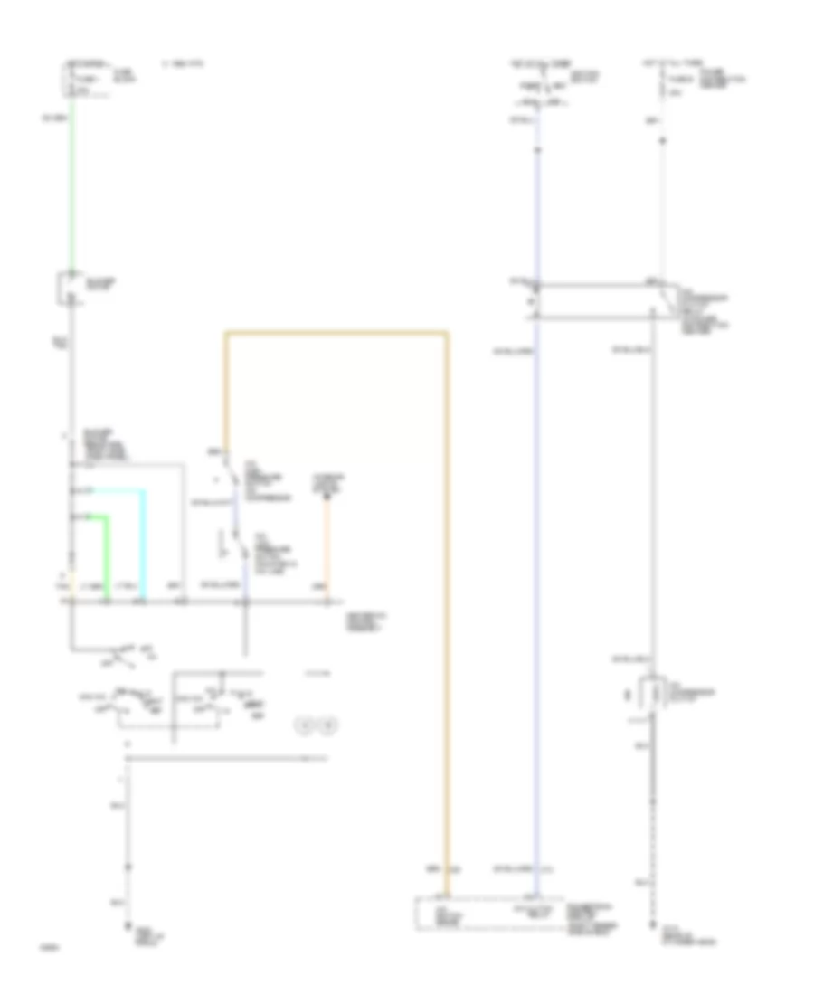
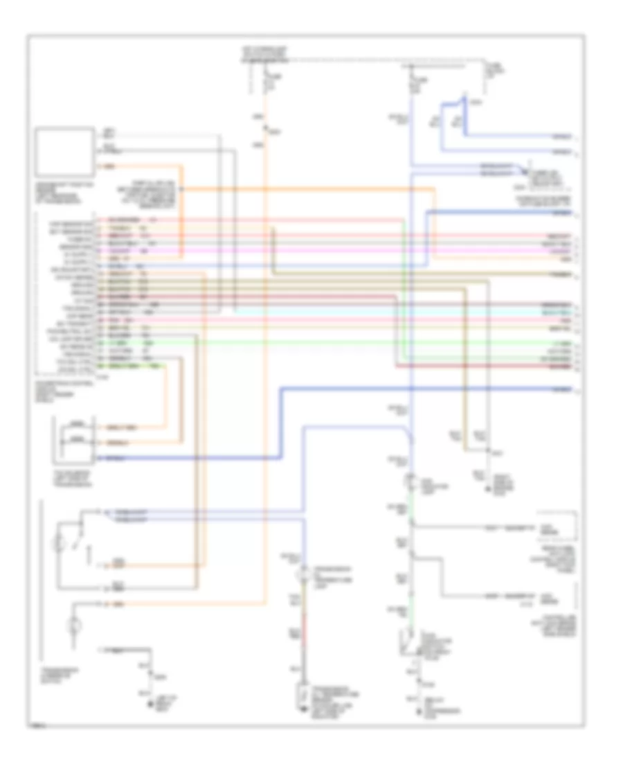
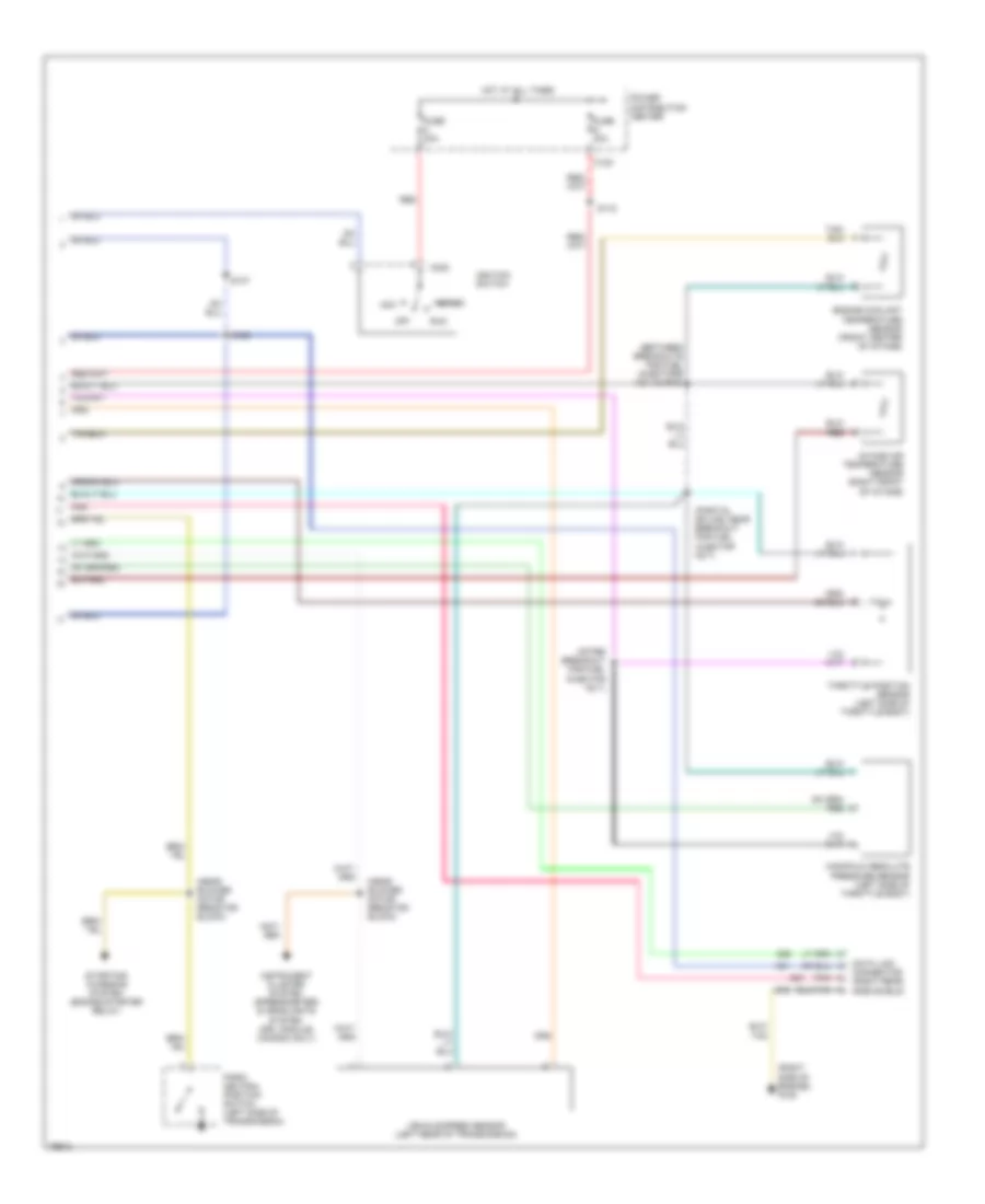
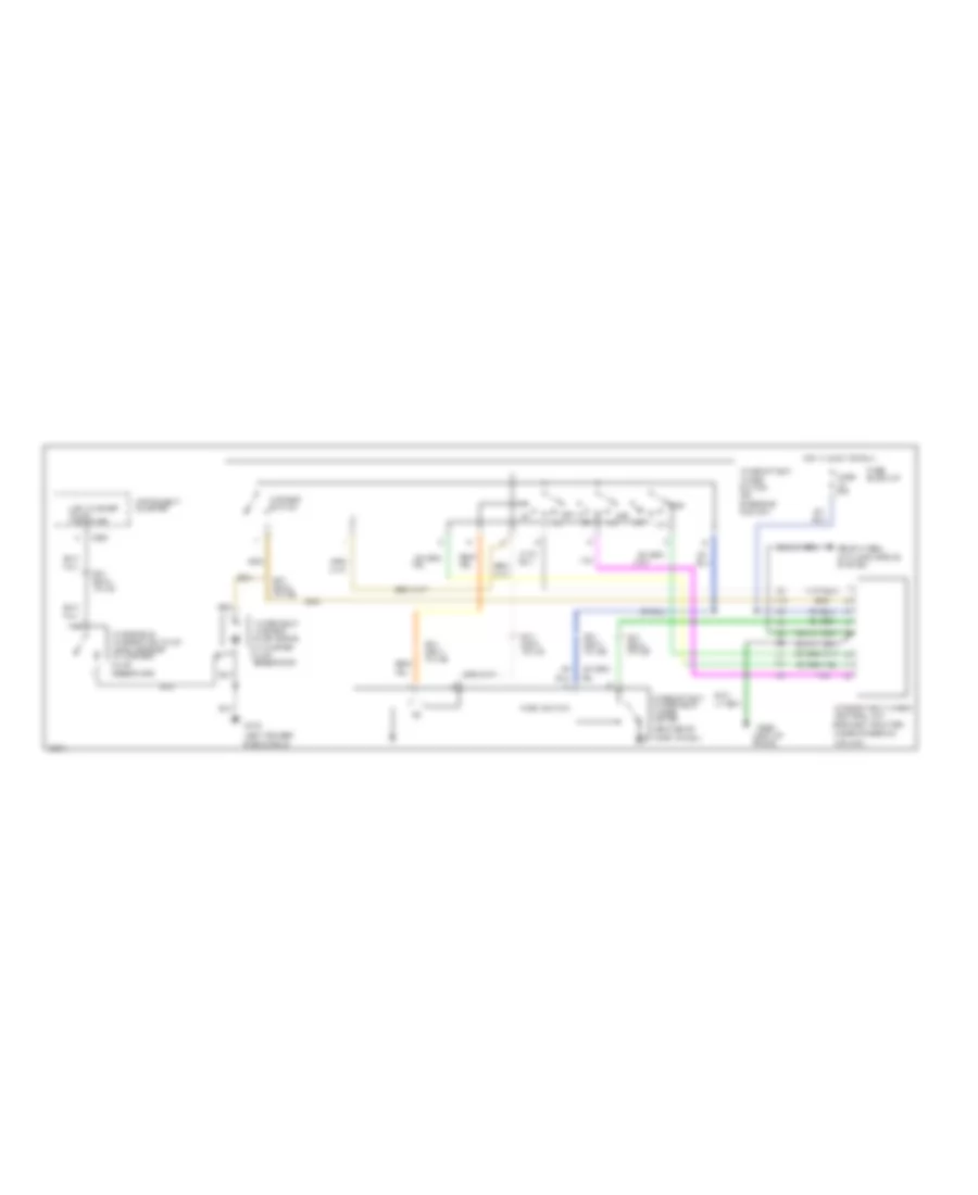
2.5L, A/C Wiring Diagram for Dodge Dakota 1995
 https://portal-diagnostov.com/license.html
Automotive Electricians Portal FZCO
Automotive Electricians Portal FZCO
https://portal-diagnostov.com/license.html
https://portal-diagnostov.com/license.html
Automotive Electricians Portal FZCO
Automotive Electricians Portal FZCO
List of elements for 2.5L, A/C Wiring Diagram for Dodge Dakota 1995:
- l
- (right fender side shield)
- 30a
- A/c
- A/c clutch
- A/c compressor clutch
- A/c compressor clutch relay (in power distribution center)
- A/c high pressure switch (on compressor)
- A/c low pressure switch (mounted in a/c line)
- A/c switch sense
- Acc
- Blower motor
- Blower motor resistors (right side dash panel)
- C 1995 vftc
- C13
- C20
- Cooling fan motor
- Def
- Diode d101
- Fan relay
- Fuse 1
- Fuse b
- Fuse block
- G100 (left fender side shield)
- G110 (rear of cylinder head)
- G202 (left of radio)
- Heat
- Heater-a/c control assembly
- Hi/lo
- Hot at all times
- Hot in run
- Ignition switch
- Interior lights system
- Max a/c
- Off
- Pnk
- Power distribution center
- Powertrain control module
- Radiator fan control relay (in power distribution center)
- Relay
- Run
- Start
- Tan
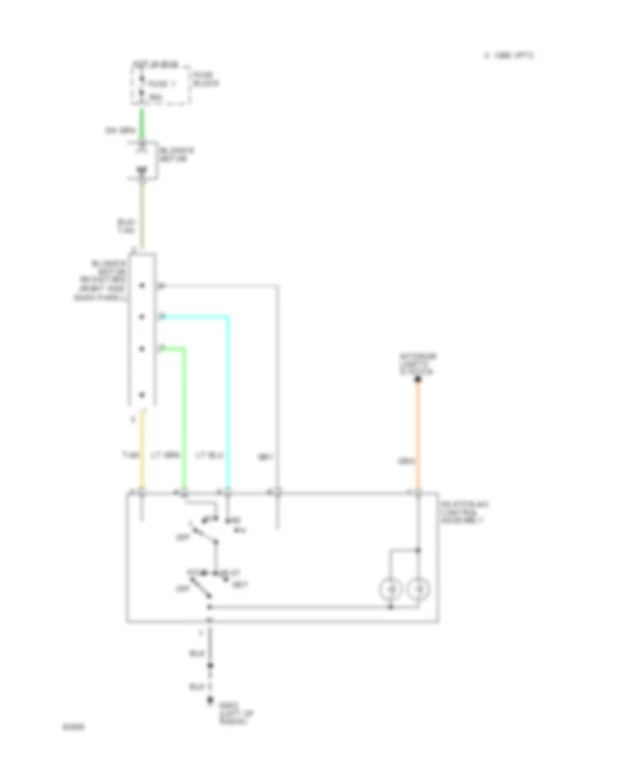
Heater Wiring Diagram for Dodge Dakota 1995
List of elements for Heater Wiring Diagram for Dodge Dakota 1995:
- l
- 30a
- Blower motor
- Blower motor resistors (right side dash panel)
- C 1995 vftc
- Def
- Fuse 1
- Fuse block
- G202 (left of radio)
- Heat
- Heater-a/c control assembly
- Hi/lo
- Hot in run
- Interior lights system
- Off
- Tan
3.9L
3.9L, A/C Wiring Diagram for Dodge Dakota 1995
List of elements for 3.9L, A/C Wiring Diagram for Dodge Dakota 1995:
- l
- (right fender side shield)
- 30a
- A/c
- A/c clutch
- A/c compressor clutch
- A/c compressor clutch relay (in power distribution center)
- A/c high pressure switch (on compressor)
- A/c low pressure switch (mounted in a/c line)
- A/c switch sense
- Acc
- Blower motor
- Blower motor resistors (right side dash panel)
- C 1995 vftc
- C13
- C20
- Def
- Fuse 1
- Fuse b
- Fuse block
- G110 (rear of cylinder head)
- G202 (left of radio)
- Heat
- Heater-a/c control assembly
- Hi/lo
- Hot at all times
- Hot in run
- Ignition switch
- Interior lights system
- Max a/c
- Off
- Power distribution center
- Powertrain control module
- Relay
- Run
- Start
- Tan
Heater Wiring Diagram for Dodge Dakota 1995
List of elements for Heater Wiring Diagram for Dodge Dakota 1995:
- l
- 30a
- Blower motor
- Blower motor resistors (right side dash panel)
- C 1995 vftc
- Def
- Fuse 1
- Fuse block
- G202 (left of radio)
- Heat
- Heater-a/c control assembly
- Hi/lo
- Hot in run
- Interior lights system
- Off
- Tan
5.2L
5.2L, A/C Wiring Diagram for Dodge Dakota 1995
List of elements for 5.2L, A/C Wiring Diagram for Dodge Dakota 1995:
- l
- (right fender side shield)
- 30a
- A/c
- A/c clutch
- A/c compressor clutch
- A/c compressor clutch relay (in power distribution center)
- A/c high pressure switch (on compressor)
- A/c low pressure switch (mounted in a/c line)
- A/c switch sense
- Acc
- Blower motor
- Blower motor resistors (right side dash panel)
- C 1995 vftc
- C13
- C20
- Def
- Fuse 1
- Fuse b
- Fuse block
- G110 (rear of cylinder head)
- G202 (left of radio)
- Heat
- Heater-a/c control assembly
- Hi/lo
- Hot at all times
- Hot in run
- Ignition switch
- Interior lights system
- Max a/c
- Off
- Power distribution center
- Powertrain control module
- Relay
- Run
- Start
- Tan
Heater Wiring Diagram for Dodge Dakota 1995
List of elements for Heater Wiring Diagram for Dodge Dakota 1995:
- l
- 30a
- Blower motor
- Blower motor resistors (right side dash panel)
- C 1995 vftc
- Def
- Fuse 1
- Fuse block
- G202 (left of radio)
- Heat
- Heater-a/c control assembly
- Hi/lo
- Hot in run
- Interior lights system
- Off
- Tan
ANTI-LOCK BRAKES
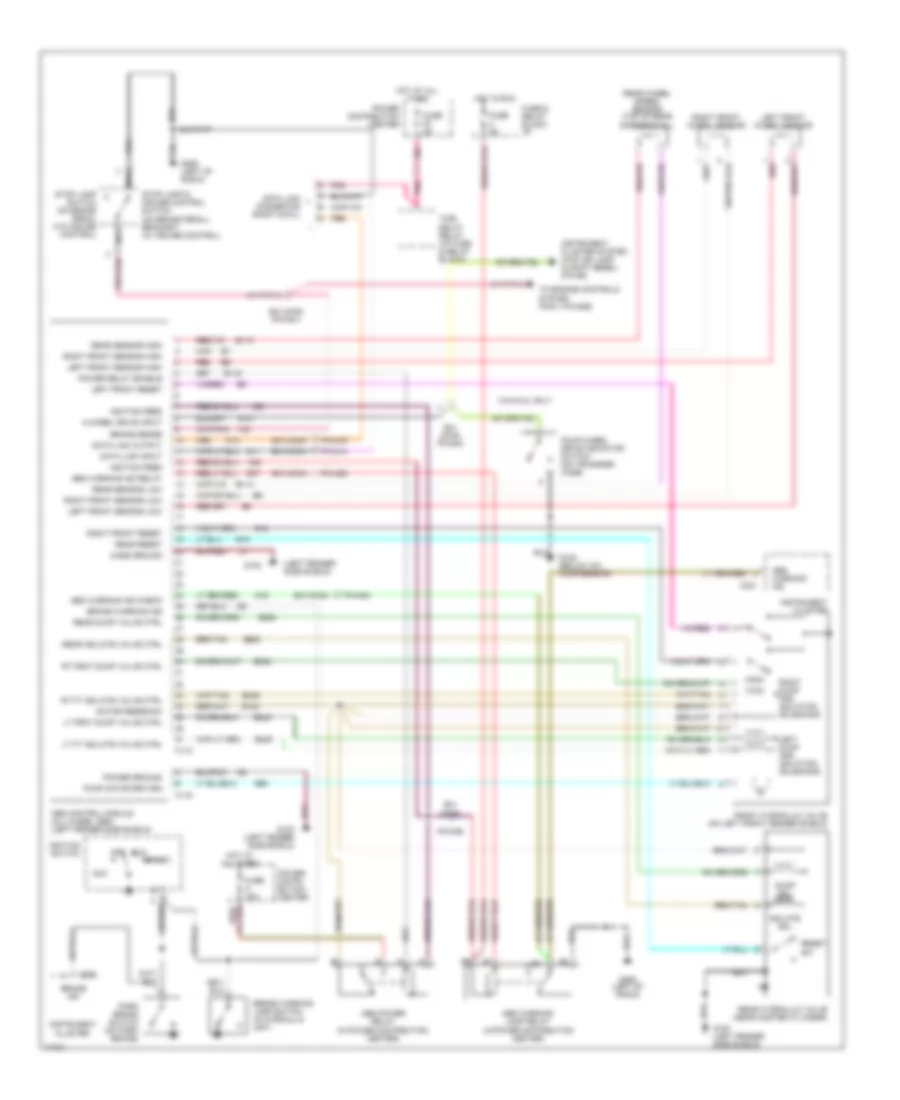
All-Wheel ABS Wiring Diagram for Dodge Dakota 1995
List of elements for All-Wheel ABS Wiring Diagram for Dodge Dakota 1995:
- (left fender side shield)
- 3.9 & 5.2l only
- 4-wheel drive input
- A20
- Abs control module (all-wheel abs) (left fender side shield)
- Abs power relay (in power distribution center)
- Abs warning ind
- Abs warning ind check
- Abs warning ind relay
- Abs warning lamp relay (in power distribution center)
- Acc
- B/h conn
- B/h conn (pin #41)
- B/h conn pin #40
- B113
- B114
- B116
- B120
- B18
- B19
- B243
- B245
- B248
- B249
- B252
- B254
- B47
- B60
- Brake ind
- Brake sense
- Brake warning ind
- Brake warning lamp switch (in hydraulic unit)
- C118
- C119
- C221
- Case ground
- D11
- D12
- Data link connector (right cowl)
- Data link input
- Data link output
- Dump sol
- Four wheel drive indicator switch (on transfer case)
- Front hydraulic valve (on left front fender shield)
- Fuse & relay block: i/p
- Fuse 5a
- Fuse a 40a
- Fuse f2 5a
- G100 (left fender side shield)
- G102
- G107
- G125 (below a/c compressor)
- G19
- G206 (left of radio)
- Hot at all times
- Hot in run
- Ignition feed
- Ignition switch
- Instrument cluster
- Instrument cluster system (4wd ind lamp in shift bezel) (pin #6)
- Isolate sol
- Left dump and isolation solenoids
- Left front reset
- Left front sensor high
- Left front sensor low
- Left front wheel sensor
- Lt frnt dump valve ctrl
- Lt ft isolate valve ctrl
- Motor feedback
- Nca
- Off
- Park brake switch (on park brake)
- Pin #14
- Pin #16
- Pin #28
- Pin #34
- Pin #39
- Pnk
- Power distri- bution center
- Power distribution center
- Power ground
- Power relay enable
- Pump motor return
- Rear dump valve ctrl
- Rear hydraulic valve (near master cylinder)
- Rear isolate valve ctrl
- Rear reset
- Rear sensor high
- Rear sensor low
- Rear wheel speed sensor (top of rear differential)
- Red
- Reset sw
- Right dump and isolation solenoids
- Right front reset
- Right front sensor high
- Right front sensor low
- Right front wheel sensor
- Rt frnt dump valve ctrl
- Rt ft isolate valve ctrl
- Run
- Start
- Stop lamp & cruise control switch (on brake pedal) bracket) (w/ cruise control)
- Stop lamp switch (on brake pedal w/o cruise control)
- Time delay relay (i/p fuse & relay block)
- To engine controls system (pcm ii pin #29)
- V40
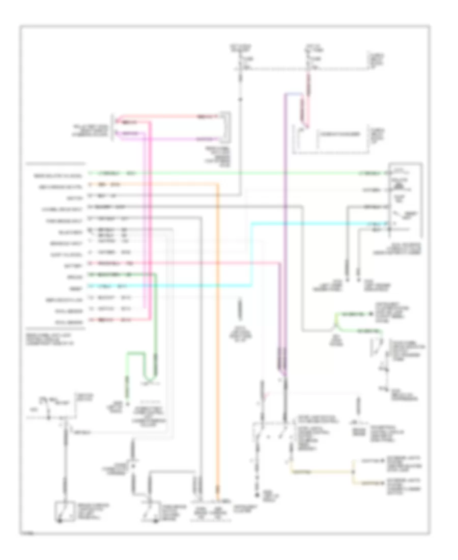
Rear Wheel ABS Wiring Diagram for Dodge Dakota 1995
List of elements for Rear Wheel ABS Wiring Diagram for Dodge Dakota 1995:
- (stop lamp switch w/o cruise control)
- 4-wheel drive input
- Abs warning ind
- Abs warning ind ctrl
- Acc
- B/h conn pin #40
- B101
- B102
- B108
- B111
- B112
- B113
- B114
- Battery
- Brake sense
- Brake sw input
- Brake warning lamp switch (on left frame rail)
- Bulb check
- C221
- Combination buzzer
- Data link conn (right side of i/p)
- Diode (taped in i/p harness)
- Dual solenoid hydraulic valve (near master cylinder)
- Dump sol
- Dump valve sol
- Exterior lights system (center mounted stop lamp)
- Exterior lights system (hazard flasher switch)
- F32
- Four wheel drive indicator switch (on transfer case)
- Fuse & relay block: (i/p
- Fuse & relay block: i/p
- Fuse 10a
- Fuse 20a
- G100 (left fender side shield)
- G104 (left inner fender panel)
- G11
- G125 (below a/c compressor)
- G206 (left of radio)
- Ground
- Hot at all times
- Hot in run or start
- Ignition
- Ignition switch
- Instrument cluster
- Instrument cluster system (4wd ind lamp in shift bezel) (pin #6)
- Intermittent wiper control unit (under steering column)
- Isolate sol
- Nca
- Off
- Park brake ind
- Park brake input
- Park brake switch (on park brake)
- Powertrain control module (center of dash panel)
- Rear isolate valve sol
- Rear wheel anti-lock control module (under right side of i/p)
- Rear wheel anti-lock sensor (top of rear axle)
- Reset
- Reset sw
- Rolls test conn (right side of steering column)
- Run
- Rwal sensor
- Service data link
- Start
- Stop lamp & cruise control switch (on brake pedal bracket)
- V40
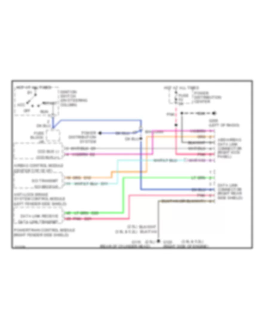
COMPUTER DATA LINES
Computer Data Lines for Dodge Dakota 1995
List of elements for Computer Data Lines for Dodge Dakota 1995:
- (2.5l)
- (3.9l & 5.2l)
- (center top of i/p)
- (left fender side shield)
- (rear of cylinder head)
- (right fender side shield)
- Abs/airbag data link connector (right kick panel)
- Acc
- Airbag control module
- Anti-lock brake system control module
- B/h conn
- Ccd bus (+)
- Ccd bus (-)
- D11
- D12
- D20
- D21
- Data link connector (right rear side shield)
- Data link receive
- Data link transmit
- Fuse block: i/p
- Fuse f2 5a
- G115
- G120 (right side of engine)
- G206 (left of radio)
- Hot at all times
- Ignition switch (on steering column)
- Off
- Pnk
- Power distribution center
- Power distribution system
- Powertrain control module
- Run
- Sci receive
- Sci transmit
- Start
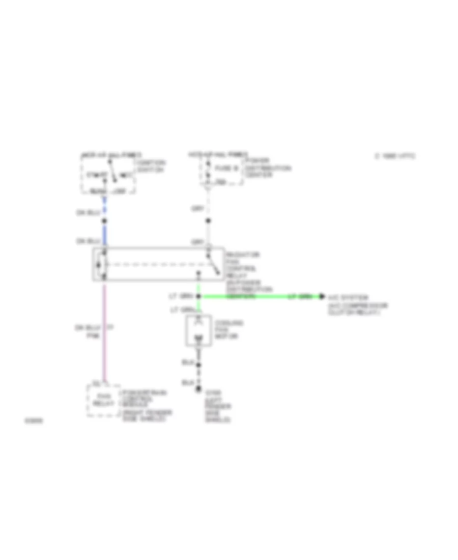
COOLING FAN
2.5L
2.5L, Cooling Fan Wiring Diagram for Dodge Dakota 1995
List of elements for 2.5L, Cooling Fan Wiring Diagram for Dodge Dakota 1995:
- (a/c compressor clutch relay)
- (right fender side shield)
- 30a
- A/c system
- Acc
- C 1995 vftc
- Cooling fan motor
- Fan relay
- Fuse b
- G100 (left fender side shield)
- Hot at all times
- Ignition switch
- Off
- Pnk
- Power distribution center
- Powertrain control module
- Radiator fan control relay (in power distribution center)
- Run
- Start
CRUISE CONTROL
Cruise Control Wiring Diagram for Dodge Dakota 1995
List of elements for Cruise Control Wiring Diagram for Dodge Dakota 1995:
- (below a/c compressor)
- (in steering wheel)
- (left of radio)
- (left side fender shield)
- (near steering column support)
- (right fender side shield)
- Anti-lock brakes system
- Anti-lock brakes system
- Assembly
- B/h conn pin 10
- B/h conn pin 41
- B/h conn pin 7
- B/h conn pin 8
- B/h conn pin 9
- Brake sense
- Clockspring
- Cruise control servo
- Cruise control switch
- Exterior lights system
- Fuse 15 2a
- Fuse 7 10a
- Fuse block: i/p
- G125
- G206
- Hot at all times
- Hot in run or start
- Nca
- Off
- On/off
- Powertrain control module
- Rear wheel
- Rear wheel anti-lock brakes system
- Resume
- Resume & acc
- Set
- Set/coast
- Stop lamp switch
- Tan/red
- V31
- V32
- V33
- V35
- V36
- V40
- Vacuum
- Vent
- Warning system (combination buzzer)
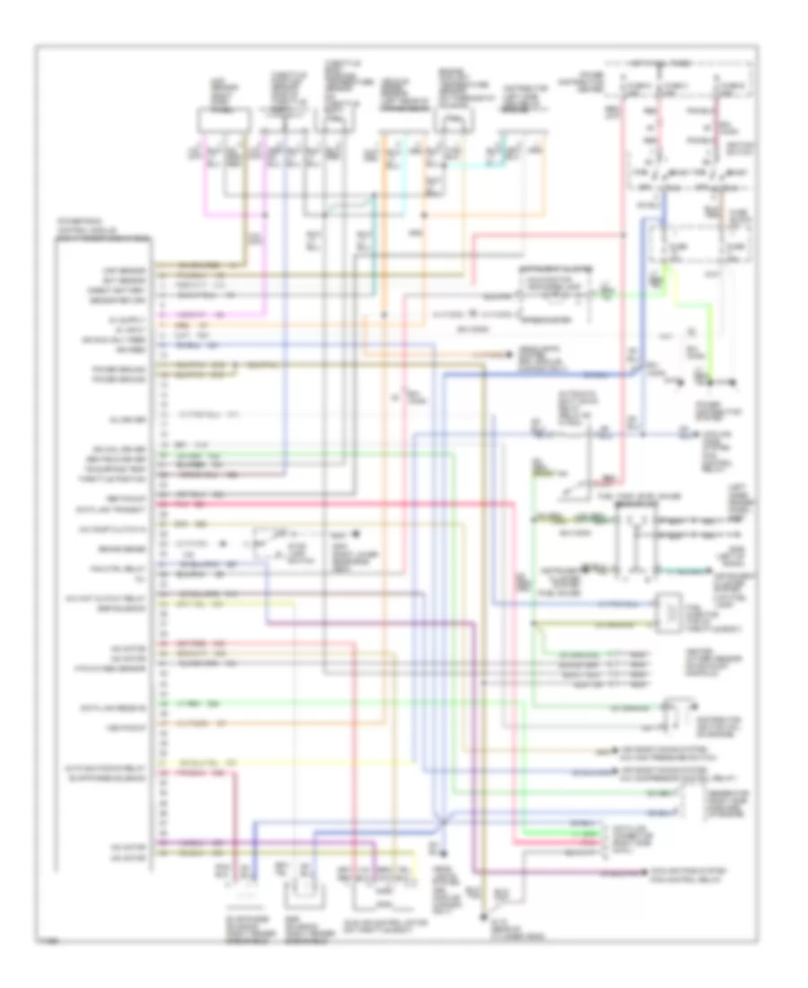
ENGINE PERFORMANCE
2.5L
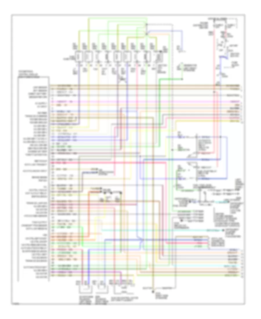
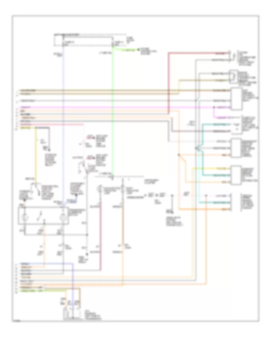
2.5L, Engine Performance Wiring Diagrams for Dodge Dakota 1995
List of elements for 2.5L, Engine Performance Wiring Diagrams for Dodge Dakota 1995:
- (a/c compressor control relay)
- (a/c high pressure switch)
- (fan control relay)
- (fuel gauge)
- (left inner fender panel) g104
- (right fender side shield)
- 8v input
- A/c comp clutch in
- A/c wot cutout relay
- A14
- A21
- Acc
- Air conditioning system
- Auto shutdown relay
- Automatic shut down relay (relay #3 in pdc)
- B/h conn
- Brake sense
- C13
- C20
- C27
- Center
- Cluster system
- Control module
- Cooling fans system
- Cooling fans system (fan control relay)
- D20
- D21
- Data link connector (right side cowl)
- Data link receive
- Data link transmit
- Direct battery
- Distribution
- Distributor (left side center of engine)
- Distributor ignition coil (on engine)
- Ect sensor
- Egr solenoid
- Egr solenoid (right fender side shield)
- Engine coolant temperature sensor (on thermostat housing)
- Evap/purge solenoid
- Evap/purge solenoid (right fender side shield)
- F20
- Fan ctrl relay
- Fuel injector (top of throttle body)
- Fuel tank level gauge
- Fuse 15a
- Fuse block: i/p
- Fuse c 40a
- Fuse d 30a
- Fuse e 50a
- G115 (rear of cylinder head)
- G203 (right lower reinforce- ment)
- G206 (left of radio)
- Gen field driver
- Generator (right side forward of engine)
- Head- lights system (drl module) (canada only)
- Headlights system (drl module) (canada only)
- Heated oxygen sensor (on exhaust manifold)
- Hot at all times
- Htd oxygen sensor
- Iac motor
- Idle air control motor (on throttle body)
- Ign coil driver
- Ign feed
- Ign run only feed
- Ignition switch
- Inj driver
- Instrument
- Instrument cluster
- Instrument cluster system (low fuel lamp)
- K11
- K19
- K20
- K21
- K22
- K24
- K35
- K39
- K40
- K41
- K51
- K52
- K59
- K60
- Malfunction indicator lamp
- Map sensor
- Map sensor (right dash panel)
- Mil
- Nca
- Off
- Pnk
- Power
- Power distribution system
- Power ground
- Powertrain
- Red
- Ref pickup
- Run
- Run a2
- Sending unit
- Sensor return
- Speedometer
- Start
- Stop lamp switch
- Tb surface temp
- Throttle body surface temperature sensor (on throttle body)
- Throttle position
- Throttle position sensor (side of throttle body)
- V40
- Vehicle speed sensor (left rear of transmission)
- Vss pickup
- Z12
3.9L
3.9L, Engine Performance Wiring Diagrams (1 of 2) for Dodge Dakota 1995
List of elements for 3.9L, Engine Performance Wiring Diagrams (1 of 2) for Dodge Dakota 1995:
- (fuel gauge)
- (left front of engine)
- (left inner fender panel) g104
- (left of radio)
- (right side shield)
- 8v input
- A/c cycling sw input
- A14
- A142
- A21
- Acc
- Air conditioning system
- Auto shutdown bat
- Auto shutdown relay
- Automatic shut down relay (relay #3 in pdc)
- B/h conn
- Brake sense
- C13
- C20
- Camshaft pos sensor
- Center
- Charge air temp
- Cluster system
- Control module
- Cruise control system
- D20
- D21
- Data link connector (right rear side shield)
- Data link receive
- Data link transmit
- Direct battery
- Distribution
- Ect sensor
- Egr solenoid
- Egr solenoid (right rear of intake)
- Evap/purge solenoid
- Evap/purge solenoid (left rear of intake)
- Fuel
- Fuel pump relay (relay #5 in pdc)
- Fuel tank level gauge sending unit
- Fuse block: i/p
- Fuse c 40a
- Fuse d 30a
- G120 (right side of engine)
- G125 (below a/c compressor)
- G206
- G21
- Gen field driver
- Generator
- Heated oxygen sensor (v6-right of engine, on exhaust pipe) (v8-center of engine, on exhaust manifold)
- Hot at all times
- Htd oxygen sensor
- Iac motor
- Idle air control motor (on throttle body)
- Ign coil driver
- Ign feed
- Ignition coil (on engine)
- Ignition switch
- Inj driver 1
- Inj driver 2
- Inj driver 3
- Inj driver 4
- Inj driver 5
- Inj driver 6
- Inj driver 7 (v8 only)
- Inj driver 8 (v8 only)
- Injectors
- Instrument
- Instrument cluster system (low fuel lamp)
- Instrument cluster system (tachometer)
- K11
- K12
- K13
- K14
- K15
- K16
- K17
- K18
- K19
- K20
- K21
- K22
- K24
- K35
- K39
- K40
- K41
- K44
- K51
- K52
- K54
- K59
- K60
- Map sensor
- Mil
- Nca
- Off
- Pnk
- Pnp sw
- Power
- Power ground
- Powertrain
- Red red
- Ref pickup
- Run
- Sensor return
- Start
- T41
- T60
- T61
- Tach output
- Tan
- Tan/red
- Tcc solenoid
- Throttle position
- Trans od lamp sig
- Trans od override
- Trans od solenoid
- V31
- V32
- V33
- V35
- V36
- V40
- V8 only
- Vs ctrl-on/off
- Vs ctrl-resume/accel
- Vs ctrl-set/coast
- Vs ctrl-vacuum
- Vs ctrl-vent
- Vss
- Wot cutout relay
- Z12
3.9L, Engine Performance Wiring Diagrams (2 of 2) for Dodge Dakota 1995
List of elements for 3.9L, Engine Performance Wiring Diagrams (2 of 2) for Dodge Dakota 1995:
- (left side of throttle body)
- A/t
- A/t only
- Anti-lock brakes system (abs module)
- Anti-lock brakes system (rwal module)
- B/h conn
- Camshaft position sensor (stator) (in distributor)
- Crankshaft position sensor (left rear side of trans- mission)
- Engine coolant temperature sensor (front center of intake)
- Fuse 14 15a
- Fuse 16 5a
- Fuse block: i/p
- G206 (left of radio)
- Headlights system (drl module) (canada only)
- Hot in run or start
- Instrument cluster
- Instrument cluster system (trans oil temp lamp)
- Intake air temperature sensor (right front of intake)
- Interior lights system (rheostat)
- M/t
- Malfunction indicator lamp
- Map sensor (on front of throttle body)
- Park/neutral position switch (left side of trans- mission)
- Power distribution system
- Shift indicator lamp
- Speedometer
- Starter relay)
- Starting system (engine
- Stop lamp switch
- Tcc solenoid (left side of transmission)
- Throttle position sensor
- Transmission overdrive switch
- Vehicle speed sensor (on rear of trans- mission)
5.2L
5.2L, Engine Performance Wiring Diagrams (1 of 2) for Dodge Dakota 1995
List of elements for 5.2L, Engine Performance Wiring Diagrams (1 of 2) for Dodge Dakota 1995:
- (fuel gauge)
- (left front of engine)
- (left inner fender panel) g104
- (left of radio)
- (right side shield)
- 8v input
- A/c cycling sw input
- A14
- A142
- A21
- Acc
- Air conditioning system
- Auto shutdown bat
- Auto shutdown relay
- Automatic shut down relay (relay #3 in pdc)
- B/h conn
- Brake sense
- C13
- C20
- Camshaft pos sensor
- Center
- Charge air temp
- Cluster system
- Control module
- Cruise control system
- D20
- D21
- Data link connector (right rear side shield)
- Data link receive
- Data link transmit
- Direct battery
- Distribution
- Ect sensor
- Egr solenoid
- Egr solenoid (right rear of intake)
- Evap/purge solenoid
- Evap/purge solenoid (left rear of intake)
- Fuel
- Fuel pump relay (relay #5 in pdc)
- Fuel tank level gauge sending unit
- Fuse block: i/p
- Fuse c 40a
- Fuse d 30a
- G120 (right side of engine)
- G125 (below a/c compressor)
- G206
- G21
- Gen field driver
- Generator
- Heated oxygen sensor (v6-right of engine, on exhaust pipe) (v8-center of engine, on exhaust manifold)
- Hot at all times
- Htd oxygen sensor
- Iac motor
- Idle air control motor (on throttle body)
- Ign coil driver
- Ign feed
- Ignition coil (on engine)
- Ignition switch
- Inj driver 1
- Inj driver 2
- Inj driver 3
- Inj driver 4
- Inj driver 5
- Inj driver 6
- Inj driver 7 (v8 only)
- Inj driver 8 (v8 only)
- Injectors
- Instrument
- Instrument cluster system (low fuel lamp)
- Instrument cluster system (tachometer)
- K11
- K12
- K13
- K14
- K15
- K16
- K17
- K18
- K19
- K20
- K21
- K22
- K24
- K35
- K39
- K40
- K41
- K44
- K51
- K52
- K54
- K59
- K60
- Map sensor
- Mil
- Nca
- Off
- Pnk
- Pnp sw
- Power
- Power ground
- Powertrain
- Red red
- Ref pickup
- Run
- Sensor return
- Start
- T41
- T60
- T61
- Tach output
- Tan
- Tan/red
- Tcc solenoid
- Throttle position
- Trans od lamp sig
- Trans od override
- Trans od solenoid
- V31
- V32
- V33
- V35
- V36
- V40
- V8 only
- Vs ctrl-on/off
- Vs ctrl-resume/accel
- Vs ctrl-set/coast
- Vs ctrl-vacuum
- Vs ctrl-vent
- Vss
- Wot cutout relay
- Z12
5.2L, Engine Performance Wiring Diagrams (2 of 2) for Dodge Dakota 1995
List of elements for 5.2L, Engine Performance Wiring Diagrams (2 of 2) for Dodge Dakota 1995:
- (left side of throttle body)
- A/t
- A/t only
- Anti-lock brakes system (abs module)
- Anti-lock brakes system (rwal module)
- B/h conn
- Camshaft position sensor (stator) (in distributor)
- Crankshaft position sensor (left rear side of trans- mission)
- Engine coolant temperature sensor (front center of intake)
- Fuse 14 15a
- Fuse 16 5a
- Fuse block: i/p
- G206 (left of radio)
- Headlights system (drl module) (canada only)
- Hot in run or start
- Instrument cluster
- Instrument cluster system (trans oil temp lamp)
- Intake air temperature sensor (right front of intake)
- Interior lights system (rheostat)
- M/t
- Malfunction indicator lamp
- Map sensor (on front of throttle body)
- Park/neutral position switch (left side of trans- mission)
- Power distribution system
- Shift indicator lamp
- Speedometer
- Starter relay)
- Starting system (engine
- Stop lamp switch
- Tcc solenoid (left side of transmission)
- Throttle position sensor
- Transmission overdrive switch
- Vehicle speed sensor (on rear of trans- mission)
EXTERIOR LIGHTS
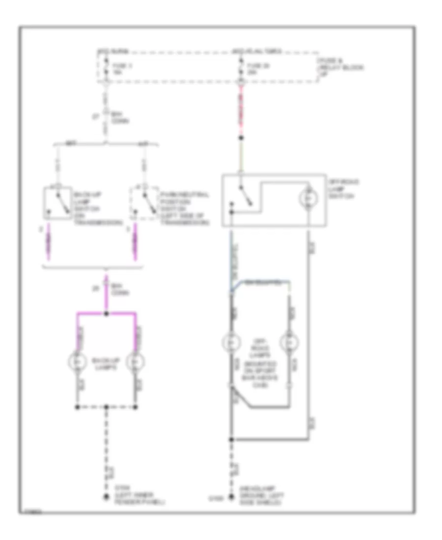
Backup & Off-Road Lamps Wiring Diagram for Dodge Dakota 1995
List of elements for Backup & Off-Road Lamps Wiring Diagram for Dodge Dakota 1995:
- (headlamp ground, left side shield)
- (mounted on sport bar above cab)
- A/t
- B/h conn
- Back-up lamp switch (on transmission)
- Back-up lamps
- Fuse & relay block: i/p
- Fuse 20 25a
- Fuse 3 15a
- G100
- G104 (left inner fender panel)
- Hot at all times
- Hot in run
- M/t
- Nca
- Off- road lamps
- Off-road lamp switch
- Park/neutral position switch (left side of transmission)
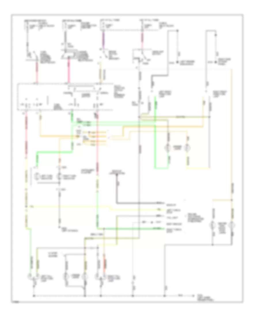
Exterior Lamps Wiring Diagram for Dodge Dakota 1995
List of elements for Exterior Lamps Wiring Diagram for Dodge Dakota 1995:
- (left fender side shield)
- (right side of dash panel)
- 2.5l
- 3.9 & 5.2l
- B/h conn
- Back-up
- Back-up lamps system
- Body ground
- Brake switch (on bracket)
- Bumper
- C220
- C221
- Center high- mount stop lamps
- Fuse & relay block: i/p
- Fuse 11 20a
- Fuse 7 10a
- Fuse 8 20a
- Fuse f1 20a
- G100
- G104 (left inner fender panel)
- G123
- G206 (left of radio)
- Hazard
- Hazard flasher (mounted in fuse & relay block)
- Hazard switch
- Head
- Headlamp switch
- Hot at all times
- Hot in accy or run
- Instrument cluster
- Left front park/turn lamp
- Left tail/ stop/turn lamp
- Left turn & stop
- Left turn indicator
- License lamps
- Marker lamps
- Multi- function switch (on steering column)
- Normal
- Off
- Park
- Pnk
- Pnk/red
- Power distribution center
- Right front park/turn lamp
- Right tail/ stop/turn lamp
- Right turn & stop
- Right turn indicator
- Tail light
- Tan
- Trailer tow wiring unterminated (if equipped)
- Turn signal flasher (mounted in fuse & relay block)
- Turn signal switch
- W/ step
GROUND DISTRIBUTION
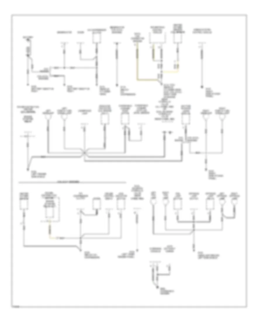
Ground Distribution Wiring Diagram (1 of 2) for Dodge Dakota 1995
List of elements for Ground Distribution Wiring Diagram (1 of 2) for Dodge Dakota 1995:
- (2.5l engine)
- (2.5l)
- (3.9l & 5.2l engines)
- (3.9l & 5.2l)
- (below a/c compressor)
- 4wd indicator switch
- A/c compressor clutch
- Airbag system control module
- Auto day/night mirror
- Battery
- Cruise control servo
- Data link connector (engine)
- Daytime running lamps module
- Diode
- Dual solenoid hydraulic valve (rear
- Engine starter relay
- Engine starter relay (m/t)
- Fog lamp switch
- G100 (headlamp ground left side shield)
- G100 (left fender side shield)
- G104 (left inner fender panel)
- G110 (rear of cylinder head)
- G115 (rear of cylinder head) g120 (right side of engine)
- G119
- G123 (right side of dash panel)
- G125 (below a/c compressor)
- G908 (windshield header)
- Genernator
- Genernator (3.9l & 5.2l engines)
- Heated oxygen sensor
- Heated oxygen sensor (2.5 l engine)
- Left fog lamp
- Left headlamp
- Left off-road lamp
- Left park & turn signal lamp
- Nca
- Off-road lamp relay
- Off-road lamp switch
- Overhead console
- Power distibution center (2.5 l engine)
- Power distribution center
- Powertrain control module
- Radiator fan motor (2.5l engine only)
- Rear hydraulic valve (all wheel abs) or dual solenoid hydraulic valve (rear wheel abs)
- Right fog lamp
- Right headlamp
- Right off-road lamp
- Right park & turn signal lamp
- Tan
- Underhood lamp
- Wheel abs)
- Windshield washer low fluid level sensor
- Windshield washer pump motor
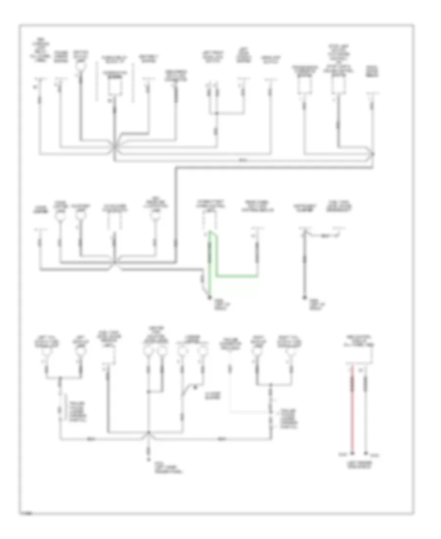
Ground Distribution Wiring Diagram (2 of 2) for Dodge Dakota 1995
List of elements for Ground Distribution Wiring Diagram (2 of 2) for Dodge Dakota 1995:
- (left fender side shield)
- A/c blower hvac switch
- Abs control module (all wheel abs)
- Abs warning lamp relay (all-wheel abs)
- Abs/airbag data link connector
- Ash receiver illumination lamp
- Center high mounted stop lamps
- Cigar lighter
- Cigar lighter lamp
- Combination buzzer
- Courtesy lamp
- Fuel tank level gauge sending unit
- Fuse & relay block: i/p
- G100
- G102
- G104 (left inner fender panel)
- G206 (left of radio)
- Headlamp switch
- Ignition switch lamp
- Instrument cluster
- Intermittent wiper control unit
- Left back-up lamp
- Left door window switch
- Left front door lock switch
- Left tail, stop & turn signal lamp
- License lamp(s)
- Power mirror switch
- Radio choke relay
- Rear wheel anti-lock control module
- Right back-up lamp
- Right tail, stop & turn signal lamp
- Seatbelt switch
- Stop lamp switch (w/o cruise control) or stop lamp & cruise control switch
- Trailer connector provision
- Trailer towing jumper harness (partial)
- Transmission overdrive switch
- W/ step bumper
HEADLIGHTS
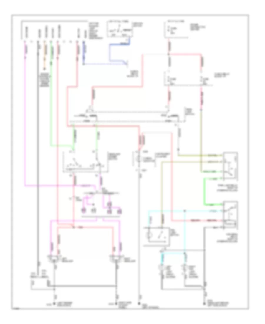
Headlamps/Fog Lamps Wiring Diagram, with DRL for Dodge Dakota 1995
List of elements for Headlamps/Fog Lamps Wiring Diagram, with DRL for Dodge Dakota 1995:
- (2.5l
- (3.9l,
- (front bumper)
- (left fender side shield)
- (right side of dash panel)
- 2.5l
- 3.9l & 5.2l
- 5.2l
- A21
- Acc
- B/h conn
- Battery
- C220
- C221
- Daytime running lamp module (right fender side shield)
- Engine controls system (vehicle speed sensor)
- Flash
- Fog lamp switch
- Fuse & relay block: i/p
- Fuse 20a
- Fuse 25a
- Fuse g 50a
- G100
- G100 (headlamp ground, left side shield)
- G123
- G206 (left of radio)
- G34
- Ground
- Head
- Head- lamp switch
- Headlamp dimmer switch
- Hi beam indicator
- High beam relay (right of steering column)
- High beams
- Hot at all times
- Ign sw
- Ignition switch
- Ind ctrl
- Instrument cluster
- L20
- Left fog lamp
- Left headlamp
- Low beam
- Off
- Only)
- Park
- Park lamp relay (right of steering column)
- Pnk/red
- Power distribution center
- Red
- Right fog lamp
- Right headlamp
- Run
- Start
- Vss signal
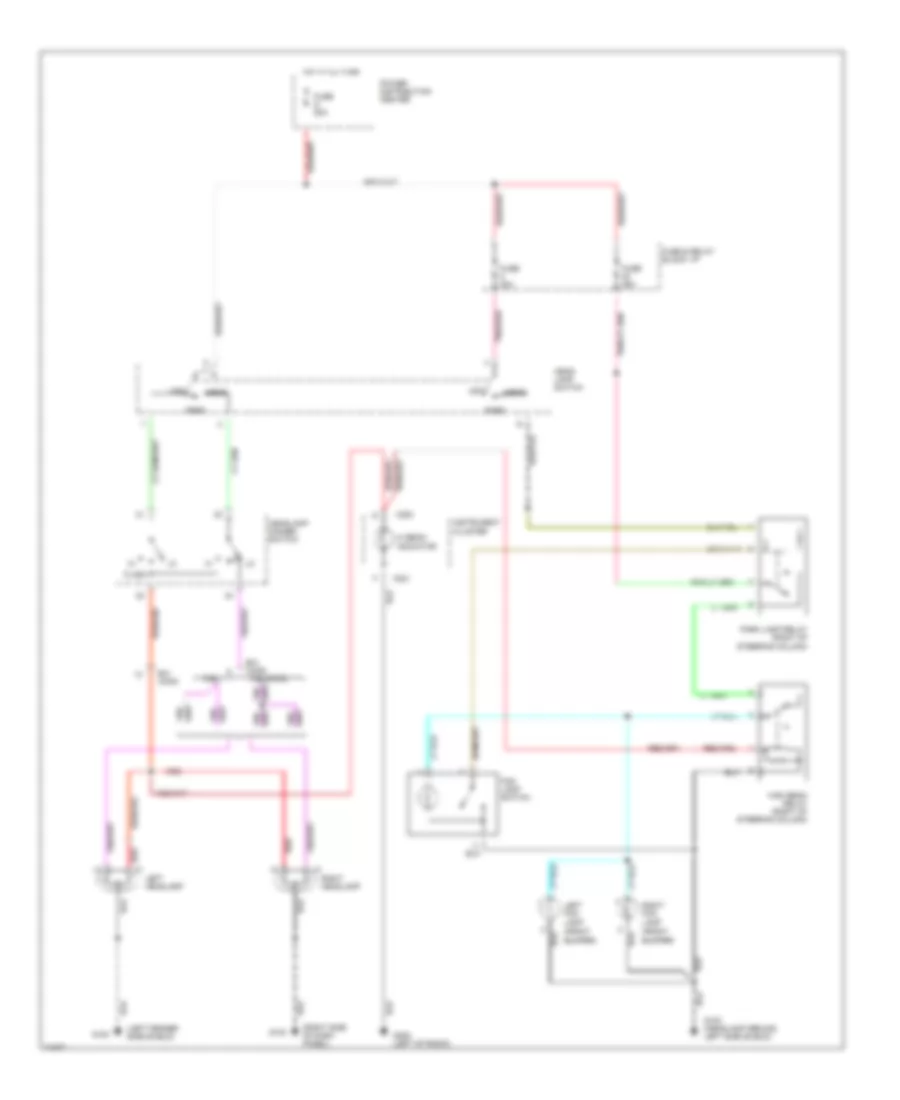
Headlamps/Fog Lamps Wiring Diagram, without DRL for Dodge Dakota 1995
List of elements for Headlamps/Fog Lamps Wiring Diagram, without DRL for Dodge Dakota 1995:
- (front bumper)
- (left fender side shield)
- (right side of dash panel)
- 2.5l
- 3.9l & 5.2l
- B/h conn
- C220
- C221
- Flash
- Fog lamp switch
- Fuse & relay block: i/p
- Fuse 20a
- Fuse 25a
- Fuse g 50a
- G100
- G100 (headlamp ground, left side shield)
- G123
- G206 (left of radio)
- Head
- Head- lamp switch
- Headlamp dimmer switch
- Hi beam indicator
- High beam relay (right of steering column)
- Hot at all times
- Instrument cluster
- Left fog lamp
- Left headlamp
- Off
- Park
- Park lamp relay (right of steering column)
- Pnk/red
- Power distribution center
- Red
- Right fog lamp
- Right headlamp
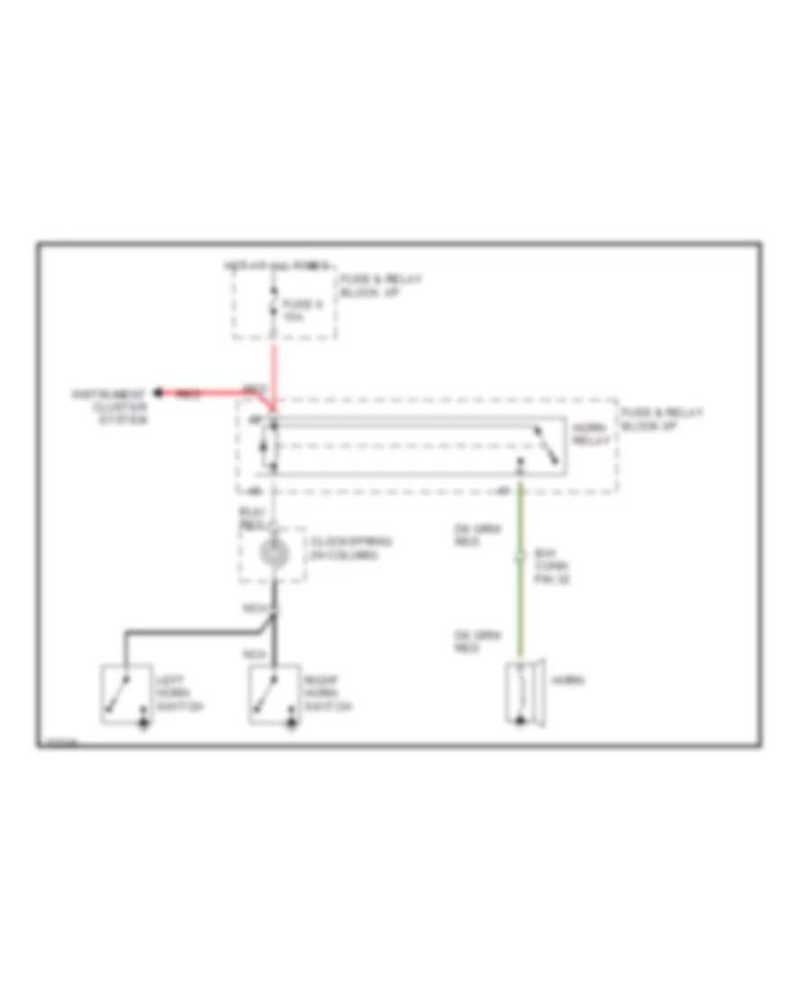
HORN
Horn Wiring Diagram for Dodge Dakota 1995
List of elements for Horn Wiring Diagram for Dodge Dakota 1995:
- B/h conn pin 32
- Clockspring (in column)
- Fuse & relay block: i/p
- Fuse & relay block:i/p
- Fuse 6 15a
- Horn
- Horn relay
- Hot at all times
- Instrument cluster system
- Left horn switch
- Nca
- Red
- Right horn switch
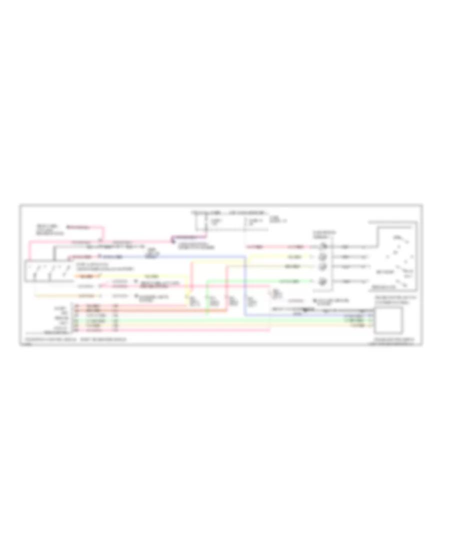
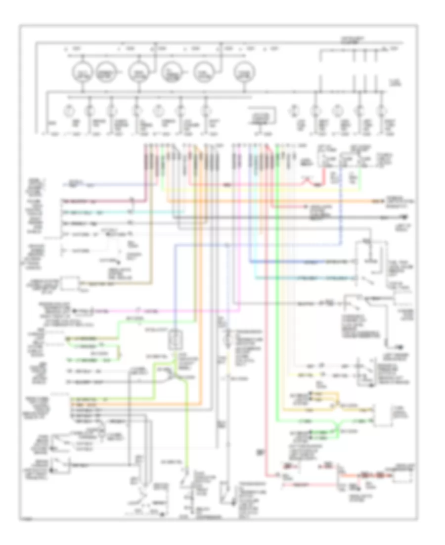
INSTRUMENT CLUSTER
Instrument Cluster Wiring Diagram for Dodge Dakota 1995
List of elements for Instrument Cluster Wiring Diagram for Dodge Dakota 1995:
- (behind right
- (below a/c compressor)
- (center top
- (in cooler line, by radiator) (3.9l & 5.2l only)
- (in fuse
- (in fuse & relay
- (in shift
- (left
- (left fender side shield)
- (left front frame rail)
- (left of radio)
- (on park brake)
- (on rear
- (on steering column cover) (3.9l & 5.2l only)
- (on thermostat box) (2.5l)
- (rear of engine)
- (rheostat)
- (right
- (right front of
- (taped in i/p
- (top of fuel tank)
- 4 wheel abs only
- 4wd indicator
- 4wd indicator switch (on front axle)
- Abs
- Abs ind.
- Acc
- Airbag ind.
- Airbag system
- Anti-lock
- B/h conn
- B102
- Bezel)
- Block)
- Brake
- Brake ind.
- C214
- C220
- C221
- Canada only
- Check engine ind.
- Combi- nation buzzer
- Control
- Control module
- Daytime running lights module (left side of engine compt)
- Dimmer switch
- Diode
- Engine coolant temperature sending unit
- Engine oil pressure switch & sending unit
- Exterior
- Fender
- Fuel gauge
- Fuel tank level gauge sending unit
- Fuse & relay block: i/p
- Fuse 15a
- Fuse 20a
- Fuse 5a
- G100
- G107
- G11
- G125
- G13
- G19
- G206
- G21
- Gnd
- Harness)
- Headlamp
- Headlamps system (high beam relay)
- Headlights system
- Headlights system (drl module)
- High beam ind.
- Horn relay
- Hot at all times
- Hot in run or start
- Ignition switch
- Illum. lamps
- Instrument cluster
- Intake) (3.9l & 5.2l)
- Interior lights system
- K54
- Lamp
- Lamp switch
- Left turn ind.
- Lights system
- Lock
- Low fuel ind.
- Low fuel warning module
- Low washer ind.
- M/t only
- Mission)
- Module
- Of i/p)
- Of trans-
- Oil press. gauge
- Oil press. ind.
- Park
- Power-
- R41
- Rear wheel
- Red
- Relay
- Right turn ind.
- Run
- Seat belt ind.
- Sensor
- Shield)
- Shift ind.
- Side
- Side of i/p)
- Speed
- Speedo- meter
- Splash shield)
- Start
- Switch
- Tacho- meter
- Tan
- Temp. gauge
- Train
- Transmission oil temperature indicator
- Transmission oil temperature switch
- Turn signal switch
- Vehicle
- Volt- meter
- W/ drl
- W/o drl
- Warning
- Washer pump motor
- Windshield washer low fluid level sensor (top of windshield washer reservoir)
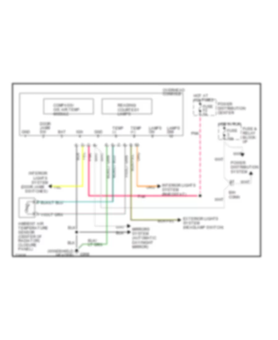
Overhead Console Wiring Diagram for Dodge Dakota 1995
List of elements for Overhead Console Wiring Diagram for Dodge Dakota 1995:
- (door jamb
- (windshield
- Ambient air temperature sensor (center of radiator) closure panel)
- B/h conn
- Bat
- Compass/ o/s air temp. module
- Door jamb sw
- Exterior lights system (headlamp switch)
- Fuse & relay block: i/p
- Fuse 10a
- Fuse f2 5a
- G908
- Gnd
- Header)
- Hot at all times
- Hot in run
- Ign
- Interior
- Interior lights system (rheostat)
- Lamps dim
- Lamps on
- Lights system
- Mirrors system (automatic day/night mirror)
- Overhead console
- Pnk
- Power distribution center
- Power distribution system
- Reading/ courtesy lamps
- Switches)
- Temp (+)
- Temp (-)
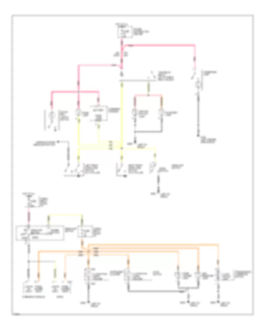
INTERIOR LIGHTS
Interior Light Wiring Diagram for Dodge Dakota 1995
List of elements for Interior Light Wiring Diagram for Dodge Dakota 1995:
- (left of radio)
- Ash receiver lamp
- B/h conn
- Battery
- C211
- C221
- Cigar lighter lamp
- Courtesy lamp
- Dimmer switch
- Dome lamp
- Dome switch
- Door jamb input
- Fuse & relay block: i/p
- Fuse 20a
- Fuse 4a
- Fuse f2 5a
- G100 (left fender side shield)
- G206
- Glove box lamp & switch
- Head
- Headlamp switch
- Hot at all times
- Hvac switch
- Ignition switch lamp
- Illumi- nation lamp
- Illumination lamps (2 bulbs)
- Illumination lamps (7 bulbs)
- Instrument cluster
- Left front door jamb switch (in "a" pillar)
- Lights on input
- Off
- Overhead console
- Panel dimmer input
- Park
- Pin #48
- Pnk
- Pnk/red
- Power distribution center
- Radio
- Right front door jamb switch (in "a" pillar)
- Tan
- Time delay relay (on i/p fuse & relay block)
- Transmission overdrive switch
- Underhood lamp
- Warning system (headlamp switch)
POWER DISTRIBUTION
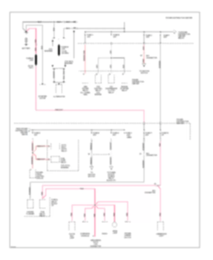
Power Distribution Wiring Diagram (1 of 4) for Dodge Dakota 1995
List of elements for Power Distribution Wiring Diagram (1 of 4) for Dodge Dakota 1995:
- (2.5l engines)
- (3.9l & 5.2l engines)
- (3.9l &5.2l engines)
- (not used)
- A/c compressor clutch relay
- Abs power relay (all wheel abs)
- Abs/airbag data link connector
- Alternator
- Auto shut down relay
- B/h connector
- Battery
- Dome lamp
- Engine starter relay
- Fan control relay (2.5l engine)
- From power distribution a center above
- Fuel pump relay
- Fuse & relay block: i/p
- Fuse a 40a
- Fuse b 30a
- Fuse c 40a
- Fuse d 30a
- Fuse e 50a
- Fuse f 20a
- Fuse f1 20a
- Fuse f2 5a
- Fuse g 50a
- Fuse h
- Fusible link
- Glove box lamp
- Hazard flasher
- Overhead console
- Pnk
- Power distribution center
- Power distribution center
- Power mirror switch
- Power- train control module
- Radio
- Red
- Starter motor
- Time delay relay
- To fuses 5-8 & 20 (fuse & relay block:i/p)
- To ignition switch
- To power distribution center below
- Underhood light
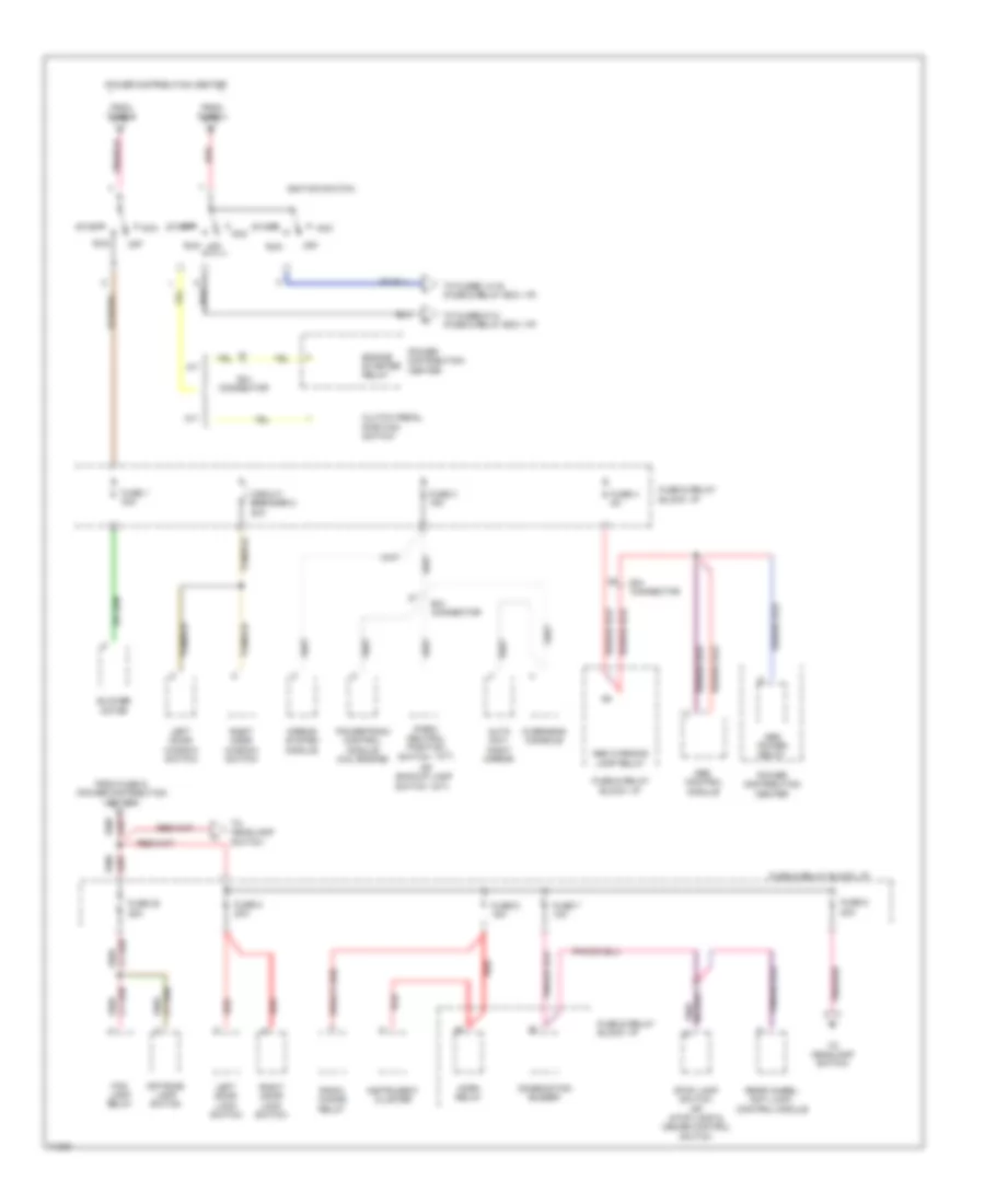
Power Distribution Wiring Diagram (2 of 4) for Dodge Dakota 1995
List of elements for Power Distribution Wiring Diagram (2 of 4) for Dodge Dakota 1995:
- (a/t)
- (m/t)
- A/t
- Abs control module
- Abs power relay
- Abs warning lamp relay
- Acc
- Airbag system module
- Auto day/ night mirror
- B/h connector
- Blower motor
- Circuit breaker 2 30a
- Clutch pedal position switch
- Combination buzzer
- Engine starter relay
- Fog lamp relay
- From fuse c
- From fuse e
- From fuse g (power distribution center)
- Fuse & relay block: i/p
- Fuse 1 30a
- Fuse 20 25a
- Fuse 3 15a
- Fuse 4 5a
- Fuse 5 20a
- Fuse 6 15a
- Fuse 7 10a
- Fuse 8 20a
- Horn relay
- Ignition switch
- Instrument cluster
- Left door lock switch
- Left door window switch
- M/t
- Off
- Off road lamp switch
- Or backup lamp
- Overhead console
- Park/ neutral position
- Pnk/
- Pnk/red
- Power distribution center
- Powertrain control module (2.5l engine)
- Radio choke relay
- Rear wheel anti lock control module
- Red
- Red/
- Right door lock switch
- Right door window switch
- Run
- Start
- Stop lamp switch or stop lamp & cruise control switch
- Switch
- To fuses 14-16 (fuse & relay box: i/p)
- To fuses 9-12 (fuse & relay box: i/p)
- To headlamp switch
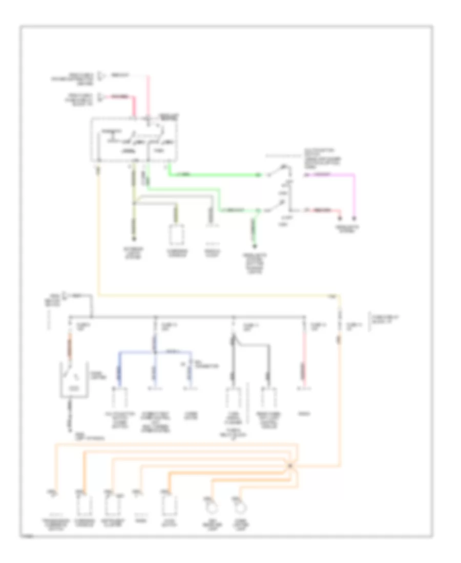
Power Distribution Wiring Diagram (3 of 4) for Dodge Dakota 1995
List of elements for Power Distribution Wiring Diagram (3 of 4) for Dodge Dakota 1995:
- (fuse & relay block: i/p)
- Ash receiver lamp
- B/h connector
- C221
- Cigar lighter
- Cigar lighter lamp
- Exterior lights system
- From fuse 8
- From fuse g (power distribution center)
- From h ignition switch
- Fuse & relay block: i/p
- Fuse 10 20a
- Fuse 11 20a
- Fuse 12 10a
- Fuse 13 4a
- Fuse 9 15a
- G206 (left of radio)
- Head
- Headlamp switch
- Headlights system
- Headlights system (daytime running lights)
- High
- Hvac switch
- Instrument cluster
- Intermittent wiper control unit (exc. 2 speed wiper system)
- Multifunction switch (headlamp dimmer switch & optical horn)
- Multifunction switch (wiper switch)
- Off
- Opt
- Overhead console
- Park
- Pnk/red
- Radio
- Radio & clock
- Rear wheel anti-lock control module
- Red/tan
- Rheostat
- Tan
- Transmission overdrive switch
- Turn signal flasher
- Wiper motor
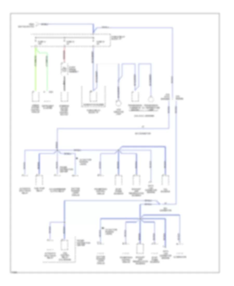
Power Distribution Wiring Diagram (4 of 4) for Dodge Dakota 1995
List of elements for Power Distribution Wiring Diagram (4 of 4) for Dodge Dakota 1995:
- (2.5l engine)
- (3.9l & 5.2 l engines)
- (3.9l & 5.2l engines)
- (engine)
- (w/ daytime running lamps)
- 4wd indicator lamp
- A/c compressor clutch relay
- Airbag system control module
- Alternator
- Automatic shut down relay
- B/h connector
- C221
- Clock spring assembly
- Combination buzzer
- Data link connector
- Data link connector (engine)
- Daytime running lamps module
- Evap/ purge solenoid
- Exhaust gas recirculation solenoid
- Fan control relay (2.5l engine)
- From ignition switch
- Fuel pump relay
- Fuse & relay block: i/p
- Fuse 14 15a
- Fuse 15 2a
- Fuse 16 5a
- Instrument cluster
- Nca
- Power distribution center
- Powertrain control module
- Steering column cruise control switch
- Tcc solenoid
- Transmission oil temperature lamp
- Transmission overdrive switch
POWER DOOR LOCKS
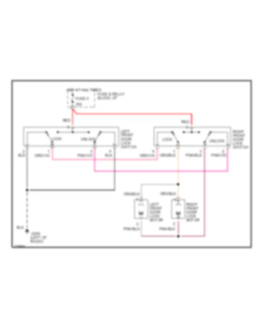
Power Door Lock Wiring Diagram for Dodge Dakota 1995
List of elements for Power Door Lock Wiring Diagram for Dodge Dakota 1995:
- (left of radio)
- 20a
- Fuse & relay block: i/p
- Fuse 5
- G206
- Hot at all times
- Left front door lock motor
- Left front door lock switch
- Lock
- Red
- Right front door lock motor
- Right front door lock switch
- Unlock
POWER MIRRORS
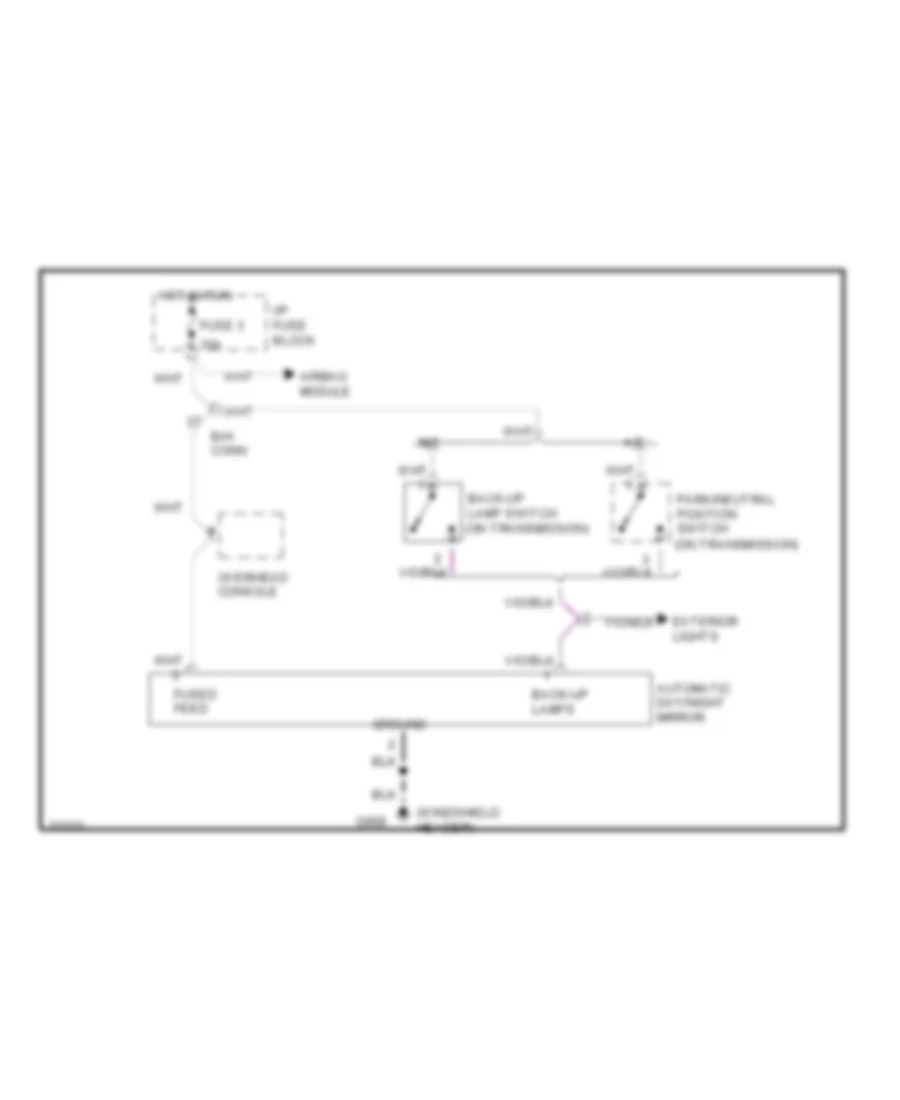
Photochromic Mirror Wiring Diagram for Dodge Dakota 1995
List of elements for Photochromic Mirror Wiring Diagram for Dodge Dakota 1995:
- (on transmission)
- (windshield header)
- 10a
- A/t
- Airbag module
- Automatic day/night mirror
- B/h conn
- Back-up lamp switch (on transmission)
- Back-up lamps
- Exterior lights
- Fuse 3
- Fused feed
- G908
- Ground
- Hot in run
- I/p fuse block
- M/t
- Overhead console
- Park/neutral position switch
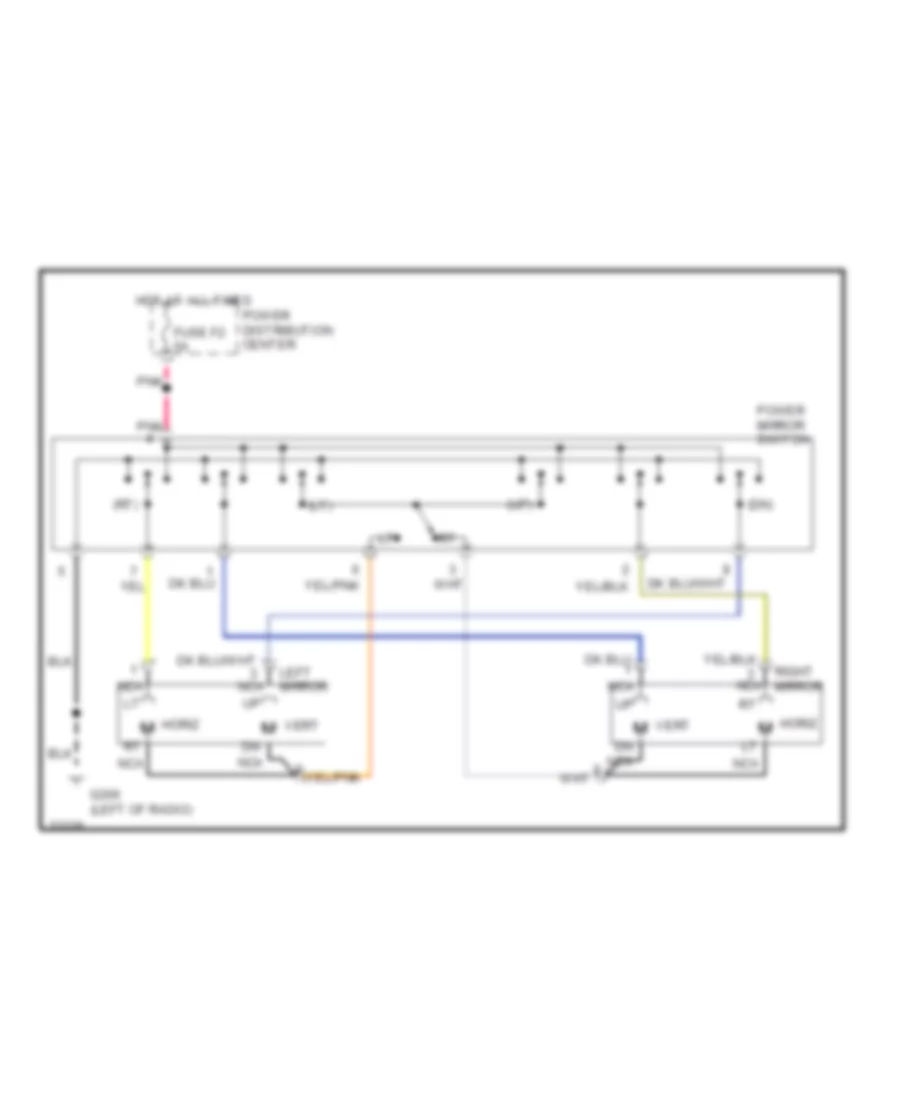
Power Mirror Wiring Diagram for Dodge Dakota 1995
List of elements for Power Mirror Wiring Diagram for Dodge Dakota 1995:
- (dn)
- (lt)
- (rt)
- (up)
- Fuse f2 5a
- G206 (left of radio)
- Horiz m
- Hot at all times
- Left mirror
- M vert
- Nca
- Pnk
- Power distribution center
- Power mirror switch
- Right mirror
- Vert
POWER WINDOWS
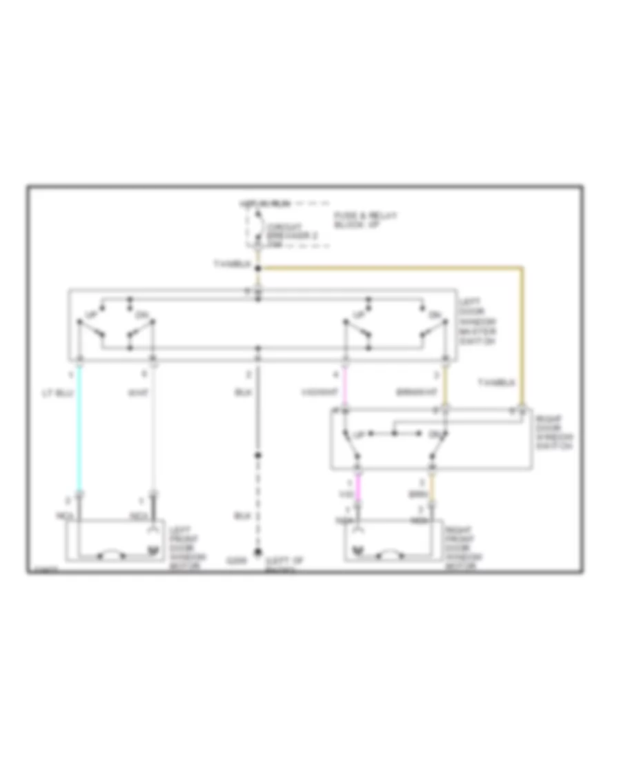
Power Window Wiring Diagram for Dodge Dakota 1995
List of elements for Power Window Wiring Diagram for Dodge Dakota 1995:
- (left of radio)
- Circuit breaker 2 30a
- Fuse & relay block: i/p
- G206
- Hot in run
- Left door window master switch
- Left front door window motor
- Nca
- Right door window switch
- Right front door window motor
RADIO
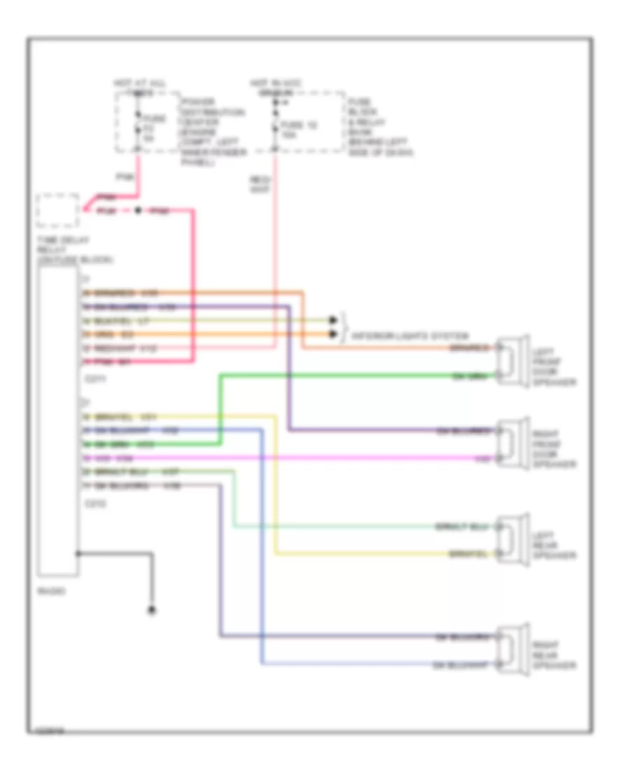
Radio Wiring Diagrams, Base for Dodge Dakota 1995
List of elements for Radio Wiring Diagrams, Base for Dodge Dakota 1995:
- C211
- C212
- Fuse 12 10a
- Fuse block & relay bank (behind left side of dash)
- Fuse f2 5a
- Hot at all times
- Hot in acc or run
- Interior lights system
- Left front door speaker
- Left rear speaker
- Pnk
- Power distribution center (engine compt, left inner fender panel)
- Radio
- Right front door speaker
- Right rear speaker
- Time delay relay (on fuse block)
- X12
- X51
- X52
- X53
- X54
- X55
- X56
- X57
- X58
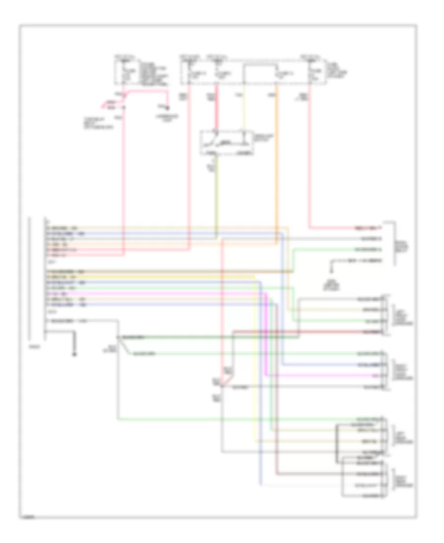
Radio Wiring Diagrams, Premium Model for Dodge Dakota 1995
List of elements for Radio Wiring Diagrams, Premium Model for Dodge Dakota 1995:
- C211
- C212
- Dimmer
- Fuse 12 10a
- Fuse 13 4a
- Fuse 20a
- Fuse 8 20a
- Fuse block (left side of dash)
- Fuse f2 5a
- G206 (center of dash)
- Head
- Headlamp switch
- Hot at all times
- Hot in acc or run
- Left front door speaker
- Left rear speaker
- Off
- Park
- Pnk
- Pnk/ red
- Power distribution center (engine compt, left inner fender panel)
- Radio
- Radio choke relay
- Right front door speaker
- Right rear speaker
- Tan
- Time delay relay (on fuse block)
- Underhood lamp
- X12
- X15
- X51
- X52
- X53
- X54
- X55
- X56
- X57
- X58
- X60
STARTING/CHARGING
2.5L
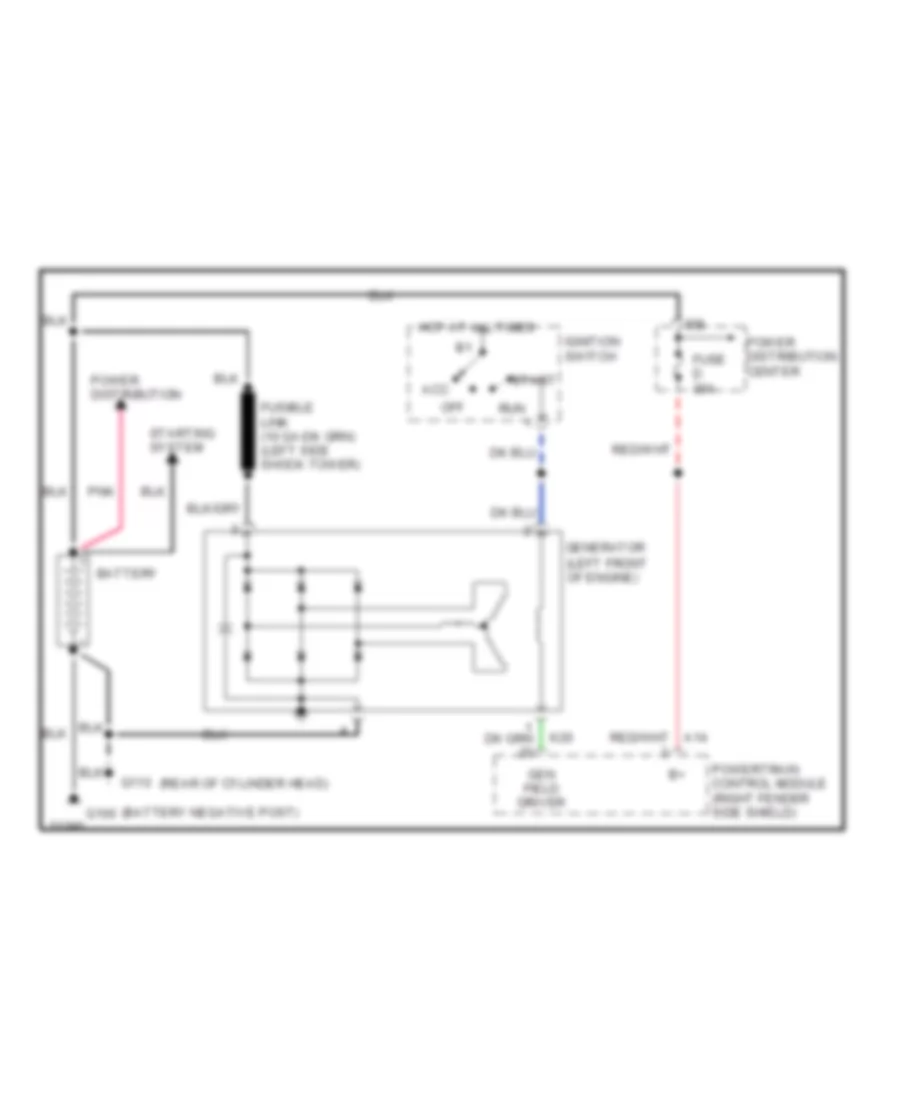
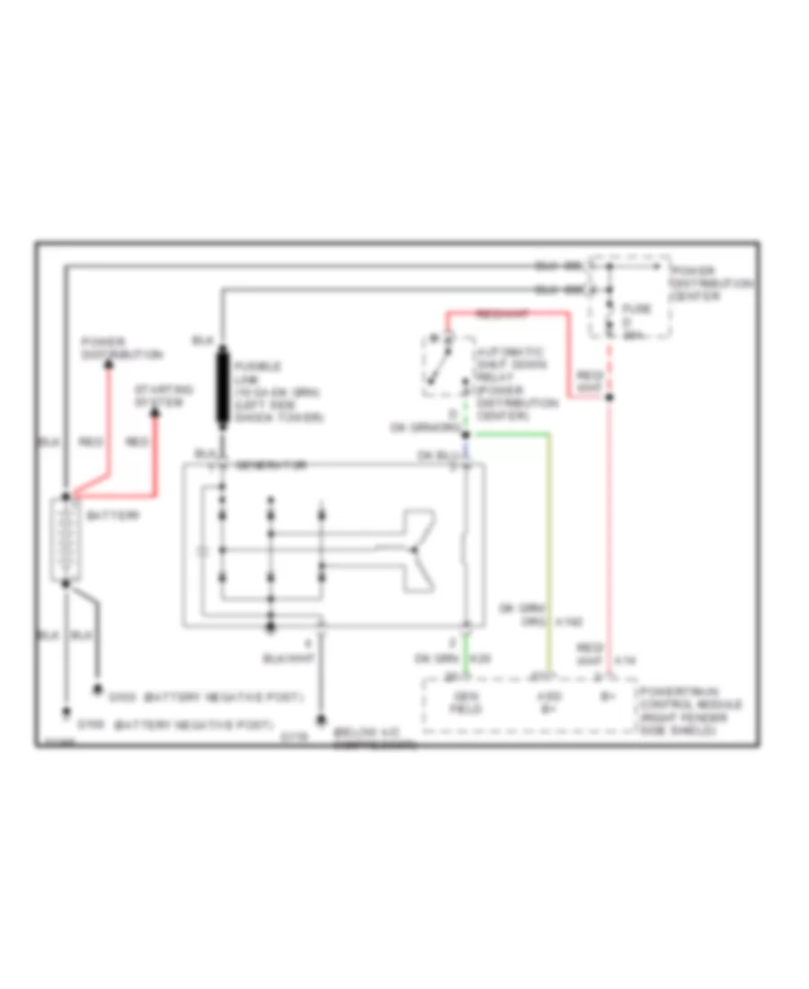
2.5L, Charging Wiring Diagram for Dodge Dakota 1995
List of elements for 2.5L, Charging Wiring Diagram for Dodge Dakota 1995:
- (left front of engine)
- (rear of cylinder head)
- Acc
- Battery
- Fuse d 30a
- G100
- G110
- Gen field driver
- Generator
- Hot at all times
- Ignition switch
- K20
- Off
- Pnk
- Power distribution
- Power distribution center
- Powertrain control module (right fender side shield)
- Run
- Start
- Starting system
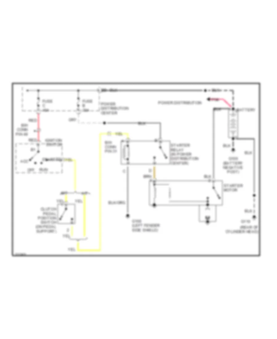
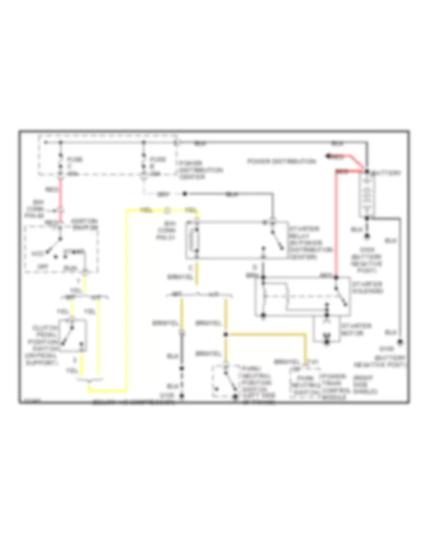
2.5L, Starting Wiring Diagram for Dodge Dakota 1995
List of elements for 2.5L, Starting Wiring Diagram for Dodge Dakota 1995:
- (rear of cylinder head)
- A/t
- Acc
- B/h conn pin 31
- B/h conn pin 49
- Battery
- Clutch pedal position switch (on pedal support)
- Fuse b 30a
- Fuse c 40a
- G100 (left fender side shield)
- G110
- Ignition switch
- M/t
- Off
- Pnk
- Power distribution
- Power distribution center
- Red
- Run
- Start
- Starter motor
- Starter relay (in power distribution center)
3.9L
3.9L, Charging Wiring Diagram for Dodge Dakota 1995
List of elements for 3.9L, Charging Wiring Diagram for Dodge Dakota 1995:
- (below a/c compressor)
- A14
- Asd b+
- Automatic shut down relay (power distribution center)
- Battery
- Fuse d 30a
- G100
- G119
- Gen field
- Generator
- Power distribution
- Power distribution center
- Powertrain control module (right fender side shield)
- Red
- Starting system
3.9L, Starting Wiring Diagram for Dodge Dakota 1995
List of elements for 3.9L, Starting Wiring Diagram for Dodge Dakota 1995:
- (right side shield)
- A/t
- Acc
- B/h conn pin 31
- B/h conn pin 49
- Battery
- Clutch pedal position switch (on pedal support)
- Fuse b 30a
- Fuse c 40a
- G100
- G125 (below a/c compressor)
- Ignition switch
- M/t
- Off
- Park neutral switch
- Park/ neutral position switch (left side of trans)
- Power distribution
- Power distribution center
- Power- train control module
- Red
- Run
- Start
- Starter motor
- Starter relay (in power distribution center)
- Starter solenoid
- T41
5.2L
5.2L, Charging Wiring Diagram for Dodge Dakota 1995
List of elements for 5.2L, Charging Wiring Diagram for Dodge Dakota 1995:
- (below a/c compressor)
- A14
- Asd b+
- Automatic shut down relay (power distribution center)
- Battery
- Fuse d 30a
- G100
- G119
- Gen field
- Generator
- Power distribution
- Power distribution center
- Powertrain control module (right fender side shield)
- Red
- Starting system
5.2L, Starting Wiring Diagram for Dodge Dakota 1995
List of elements for 5.2L, Starting Wiring Diagram for Dodge Dakota 1995:
- (right side shield)
- A/t
- Acc
- B/h conn pin 31
- B/h conn pin 49
- Battery
- Clutch pedal position switch (on pedal support)
- Fuse b 30a
- Fuse c 40a
- G100
- G125 (below a/c compressor)
- Ignition switch
- M/t
- Off
- Park neutral switch
- Park/ neutral position switch (left side of trans)
- Power distribution
- Power distribution center
- Power- train control module
- Red
- Run
- Start
- Starter motor
- Starter relay (in power distribution center)
- Starter solenoid
- T41
SUPPLEMENTAL RESTRAINTS
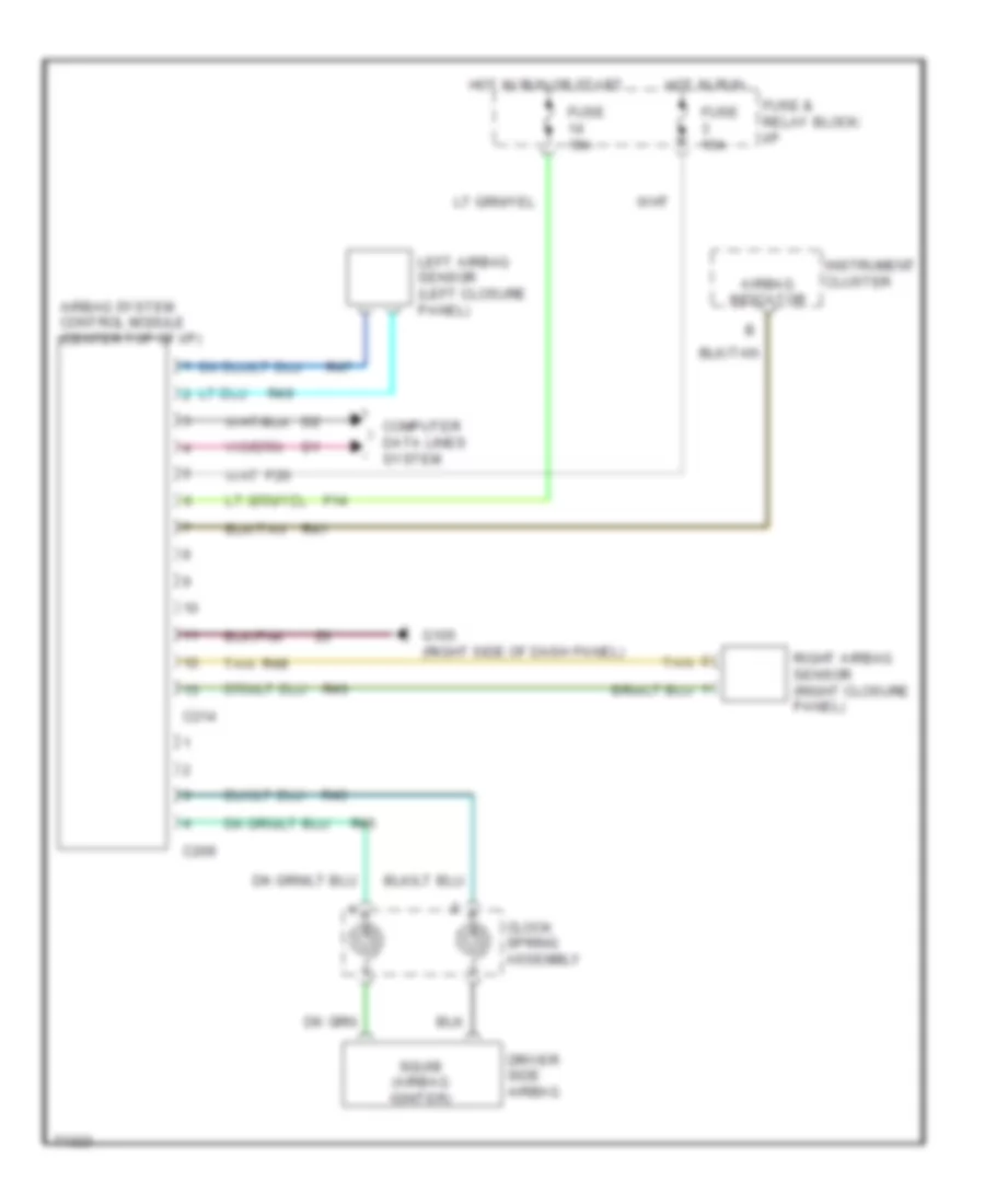
Supplemental Restraint Wiring Diagram for Dodge Dakota 1995
List of elements for Supplemental Restraint Wiring Diagram for Dodge Dakota 1995:
- Airbag indicator
- Airbag system control module (center top of i/p)
- C209
- C214
- Clock spring assembly
- Computer data lines system
- Driver side airbag
- F14
- F20
- Fuse & relay block: i/p
- Fuse 15a
- G105 (right side of dash panel)
- Hot in run
- Hot in run or start
- Instrument cluster
- Left airbag sensor (left closure panel)
- R41
- R43
- R45
- R46
- R47
- R48
- R49
- Right airbag sensor (right closure panel)
- Squib (airbag igniter)
- Tan
TRANSMISSION
3.9L
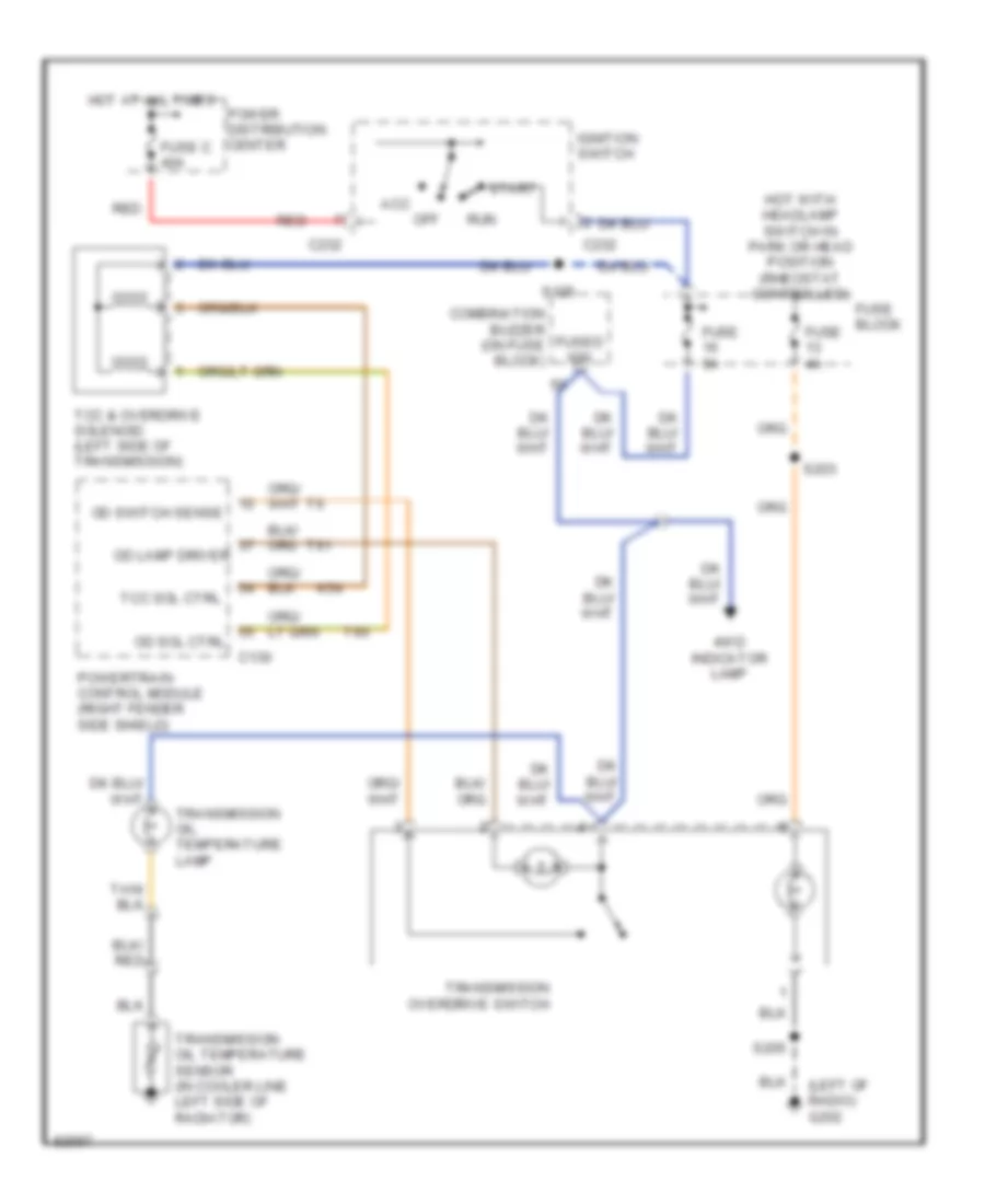
3.9L, Overdrive Wiring Diagram for Dodge Dakota 1995
List of elements for 3.9L, Overdrive Wiring Diagram for Dodge Dakota 1995:
- (left of radio) g202
- 4wd indicator lamp
- Acc
- C130
- C232
- Combination buzzer (on fuse block)
- Fuse 4a
- Fuse 5a
- Fuse block
- Fuse c 40a
- Fused ign
- Hot at all times
- Hot with headlamp switch in park or head position (rheostat controlled)
- Ignition switch
- K54
- Od lamp driver
- Od sol ctrl
- Od switch sense
- Off
- Power distribution center
- Powertrain control module (right fender side shield)
- Red
- Run
- S125
- S203
- S205
- Start
- T60
- T61
- Tcc & overdrive solenoid (left side of transmission)
- Tcc sol ctrl
- Transmission oil temperature lamp
- Transmission oil temperature sensor (in cooler line left side of radiator)
- Transmission overdrive switch
3.9L, Transmission Wiring Diagram (1 of 2) for Dodge Dakota 1995
List of elements for 3.9L, Transmission Wiring Diagram (1 of 2) for Dodge Dakota 1995:
- (below a/c compressor) g125
- (left of radio) g206
- (partial splice; between breakouts for fuel injector no.7 & oil pressure sending unit)
- (right side of engine) g120
- 4wd indicator lamp
- 4wd indicator switch (on front axle)
- 4wd sense
- A14
- A21
- C118
- C130
- C234
- Ckp sens
- Combination buzzer (on fuse block: i/p)
- Controller anti-lock brake (left fender side shield)
- Crankshaft position sensor (left rear side of transmission)
- D20
- D21
- Ect sensor sig
- Fuse 4a
- Fuse 5a
- Fuse block: i/p
- Fused b+
- Fused ign sw output (run/start)
- G107
- Ground
- Hot w/headlamp switch in park or head position
- Iat sig
- Ign (run/start)
- K21
- K22
- K24
- K54
- Map sensor sig
- O/d lamp driver
- O/d sol ctrl
- O/d sw sense
- Pak/neutral sw
- Pnk
- Powertrain control module (right fender shield
- Rear wheel anti-lock control module (right kick panel)
- S121
- S129
- S203
- S205
- Sci receive
- Sci transmit
- Sensor gnd
- T41
- T60
- T61
- Tcc sol ctrl
- Tcc solenoid (left side of transmission)
- Tps signal
- Transmission oil temperature lamp
- Transmission oil temperature sensor (in cooler line left side of radiator)
- Transmission overdrive switch
- Vss signal
- Z12
3.9L, Transmission Wiring Diagram (2 of 2) for Dodge Dakota 1995
List of elements for 3.9L, Transmission Wiring Diagram (2 of 2) for Dodge Dakota 1995:
- (after breakout for fuel injector no.1)
- (between breakouts for fuel injectors no.4 & no.6)
- (near blower motor resistor block)
- (partial splice; near breakout for fuel injector no.7)
- (right side of engine) g120
- A21
- Acc
- C120
- C232
- D20
- D21
- Data link connector (right rear side shield)
- Engine coolant temperature sensor (front center of intake)
- Fuse c 40a
- Fuse d 30a
- Hot at all times
- Ignition switch
- Instrument cluster system (speedometer) & headlights system (drl module) canada only)
- Intake air temperature sensor (right front of intake)
- Manifold absolute pressure sensor (left side of throttle body)
- Off
- Park/ neutral position switch (left side of transmission)
- Pnk
- Power distribution center
- Red
- Run
- S107
- S115
- S125
- Start
- Starting/ charging system (engine starter relay)
- Throttle position sensor (left side of throttle body)
- Vehicle speed sensor (left rear of transmission)
- Z12
5.2L
5.2L CNG, Overdrive Wiring Diagram for Dodge Dakota 1995
List of elements for 5.2L CNG, Overdrive Wiring Diagram for Dodge Dakota 1995:
- (left of radio) g202
- 4wd indicator lamp
- Acc
- C130
- C232
- Combination buzzer (on fuse block)
- Fuse 4a
- Fuse 5a
- Fuse block
- Fuse c 40a
- Fused ign
- Hot at all times
- Hot with headlamp switch in park or head position (rheostat controlled)
- Ignition switch
- K54
- Od lamp driver
- Od sol ctrl
- Od switch sense
- Off
- Power distribution center
- Powertrain control module (right fender side shield)
- Red
- Run
- S125
- S203
- S205
- Start
- T60
- T61
- Tcc & overdrive solenoid (left side of transmission)
- Tcc sol ctrl
- Transmission oil temperature lamp
- Transmission oil temperature sensor (in cooler line left side of radiator)
- Transmission overdrive switch
5.2L CNG, Transmission Wiring Diagram (1 of 2) for Dodge Dakota 1995
List of elements for 5.2L CNG, Transmission Wiring Diagram (1 of 2) for Dodge Dakota 1995:
- (below a/c compressor) g125
- (left of radio) g206
- (partial splice; between breakouts for fuel injector no.7 & oil pressure sending unit)
- (right side of engine) g120
- 4wd indicator lamp
- 4wd indicator switch (on front axle)
- 4wd sense
- A14
- A21
- C118
- C130
- C234
- Ckp sens
- Combination buzzer (on fuse block: i/p)
- Controller anti-lock brake (left fender side shield)
- Crankshaft position sensor (left rear side of transmission)
- D20
- D21
- Ect sensor sig
- Fuse 4a
- Fuse 5a
- Fuse block: i/p
- Fused b+
- Fused ign sw output (run/start)
- G107
- Ground
- Hot w/headlamp switch in park or head position
- Iat sig
- Ign (run/start)
- K21
- K22
- K24
- K54
- Map sensor sig
- O/d lamp driver
- O/d sol ctrl
- O/d sw sense
- Pak/neutral sw
- Pnk
- Powertrain control module (right fender shield
- Rear wheel anti-lock control module (right kick panel)
- S121
- S129
- S203
- S205
- Sci receive
- Sci transmit
- Sensor gnd
- T41
- T60
- T61
- Tcc sol ctrl
- Tcc solenoid (left side of transmission)
- Tps signal
- Transmission oil temperature lamp
- Transmission oil temperature sensor (in cooler line left side of radiator)
- Transmission overdrive switch
- Vss signal
- Z12
5.2L CNG, Transmission Wiring Diagram (2 of 2) for Dodge Dakota 1995
List of elements for 5.2L CNG, Transmission Wiring Diagram (2 of 2) for Dodge Dakota 1995:
- (after breakout for fuel injector no.1)
- (between breakouts for fuel injectors no.4 & no.6)
- (near blower motor resistor block)
- (partial splice; near breakout for fuel injector no.7)
- (right side of engine) g120
- A21
- Acc
- C120
- C232
- D20
- D21
- Data link connector (right rear side shield)
- Engine coolant temperature sensor (front center of intake)
- Fuse c 40a
- Fuse d 30a
- Hot at all times
- Ignition switch
- Instrument cluster system (speedometer) & headlights system (drl module) canada only)
- Intake air temperature sensor (right front of intake)
- Manifold absolute pressure sensor (left side of throttle body)
- Off
- Park/ neutral position switch (left side of transmission)
- Pnk
- Power distribution center
- Red
- Run
- S107
- S115
- S125
- Start
- Starting/ charging system (engine starter relay)
- Throttle position sensor (left side of throttle body)
- Vehicle speed sensor (left rear of transmission)
- Z12
5.2L, Overdrive Wiring Diagram for Dodge Dakota 1995
List of elements for 5.2L, Overdrive Wiring Diagram for Dodge Dakota 1995:
- (left of radio) g202
- 4wd indicator lamp
- Acc
- C130
- C232
- Combination buzzer (on fuse block)
- Fuse 4a
- Fuse 5a
- Fuse block
- Fuse c 40a
- Fused ign
- Hot at all times
- Hot with headlamp switch in park or head position (rheostat controlled)
- Ignition switch
- K54
- Od lamp driver
- Od sol ctrl
- Od switch sense
- Off
- Power distribution center
- Powertrain control module (right fender side shield)
- Red
- Run
- S125
- S203
- S205
- Start
- T60
- T61
- Tcc & overdrive solenoid (left side of transmission)
- Tcc sol ctrl
- Transmission oil temperature lamp
- Transmission oil temperature sensor (in cooler line left side of radiator)
- Transmission overdrive switch
5.2L, Transmission Wiring Diagram (1 of 2) for Dodge Dakota 1995
List of elements for 5.2L, Transmission Wiring Diagram (1 of 2) for Dodge Dakota 1995:
- (below a/c compressor) g125
- (left of radio) g206
- (partial splice; between breakouts for fuel injector no.7 & oil pressure sending unit)
- (right side of engine) g120
- 4wd indicator lamp
- 4wd indicator switch (on front axle)
- 4wd sense
- A14
- A21
- C118
- C130
- C234
- Ckp sens
- Combination buzzer (on fuse block: i/p)
- Controller anti-lock brake (left fender side shield)
- Crankshaft position sensor (left rear side of transmission)
- D20
- D21
- Ect sensor sig
- Fuse 4a
- Fuse 5a
- Fuse block: i/p
- Fused b+
- Fused ign sw output (run/start)
- G107
- Ground
- Hot w/headlamp switch in park or head position
- Iat sig
- Ign (run/start)
- K21
- K22
- K24
- K54
- Map sensor sig
- O/d lamp driver
- O/d sol ctrl
- O/d sw sense
- Pak/neutral sw
- Pnk
- Powertrain control module (right fender shield
- Rear wheel anti-lock control module (right kick panel)
- S121
- S129
- S203
- S205
- Sci receive
- Sci transmit
- Sensor gnd
- T41
- T60
- T61
- Tcc sol ctrl
- Tcc solenoid (left side of transmission)
- Tps signal
- Transmission oil temperature lamp
- Transmission oil temperature sensor (in cooler line left side of radiator)
- Transmission overdrive switch
- Vss signal
- Z12
5.2L, Transmission Wiring Diagram (2 of 2) for Dodge Dakota 1995
List of elements for 5.2L, Transmission Wiring Diagram (2 of 2) for Dodge Dakota 1995:
- (after breakout for fuel injector no.1)
- (between breakouts for fuel injectors no.4 & no.6)
- (near blower motor resistor block)
- (partial splice; near breakout for fuel injector no.7)
- (right side of engine) g120
- A21
- Acc
- C120
- C232
- D20
- D21
- Data link connector (right rear side shield)
- Engine coolant temperature sensor (front center of intake)
- Fuse c 40a
- Fuse d 30a
- Hot at all times
- Ignition switch
- Instrument cluster system (speedometer) & headlights system (drl module) canada only)
- Intake air temperature sensor (right front of intake)
- Manifold absolute pressure sensor (left side of throttle body)
- Off
- Park/ neutral position switch (left side of transmission)
- Pnk
- Power distribution center
- Red
- Run
- S107
- S115
- S125
- Start
- Starting/ charging system (engine starter relay)
- Throttle position sensor (left side of throttle body)
- Vehicle speed sensor (left rear of transmission)
- Z12
WARNING SYSTEMS
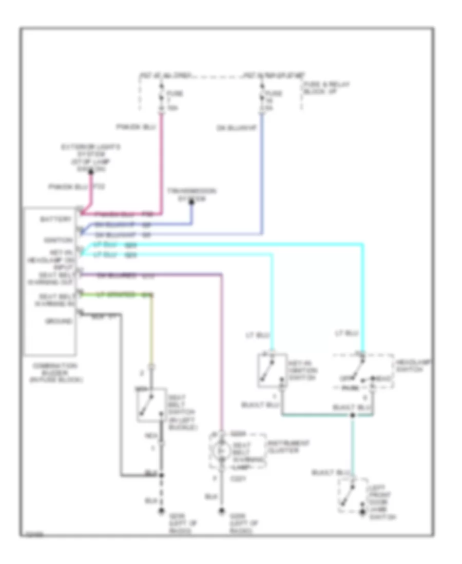
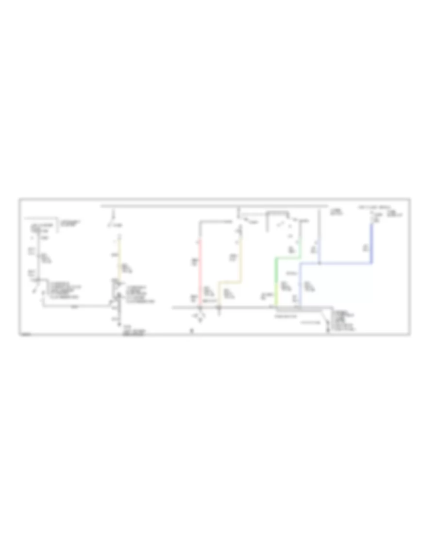
Warning System Wiring Diagrams for Dodge Dakota 1995
List of elements for Warning System Wiring Diagrams for Dodge Dakota 1995:
- Battery
- C221
- Combination buzzer (in fuse block)
- Exterior lights system (stop lamp switch)
- F32
- Fuse & relay block: i/p
- Fuse 10a
- Fuse 5a
- G206 (left of radio)
- Ground
- Head
- Headlamp switch
- Hot at all times
- Hot in run or start
- Ignition
- Instrument cluster
- Key-in ignition switch
- Key-in, headlamp on input seat belt
- Left front door jamb switch
- Nca
- Off
- Park
- Seat belt
- Seat belt switch (in left buckle)
- Seat belt warning lamp
- Transmission system
- Warning in
- Warning out
WIPER/WASHER
2-Speed Wiper/Washer Wiring Diagram for Dodge Dakota 1995
List of elements for 2-Speed Wiper/Washer Wiring Diagram for Dodge Dakota 1995:
- (in washer fluid reservoir)
- (left fender side shield)
- 2 speed windshield wiper motor (center of
- B/h conn pin 29
- B/h conn pin 30
- B/h conn pin 35
- B/h conn pin 36
- B/h conn pin 45
- B/h conn pin 46
- C220
- Dash panel)
- Fluid reservoir)
- Fuse 20a
- Fuse block:i/p
- G100
- Hot in accy or run
- Instrument cluster
- Low washer fluid indicator
- Park
- Park switch
- Red/
- Tan
- Wash
- Windshield washer low fluid level sensor (in washer
- Windshield washer pump motor
- Wiper switch
Interval Wiper/Washer Wiring Diagram for Dodge Dakota 1995
List of elements for Interval Wiper/Washer Wiring Diagram for Dodge Dakota 1995:
- (center of
- (in washer fluid reservoir)
- (left fender side shield)
- (left of radio)
- B/h conn pin 29
- B/h conn pin 30
- B/h conn pin 35
- B/h conn pin 36
- B/h conn pin 45
- B/h conn pin 46
- C220
- Column)
- Dash panel)
- Fluid
- Fuse 20a
- Fuse block:i/p
- G100
- G206
- Hot in accy or run
- Instrument cluster
- Int
- Intermittent windshield wiper motor
- Intermittent wiper control unit (bracket mounted under steering
- Intermittent wiper switch (on steering column)
- Low washer fluid indicator
- Off
- Park switch
- Rear wheel anti-lock brake system
- Red/
- Reservoir)
- Tan
- V10
- Vi7
- Washer switch
- Windshield washer low fluid level sensor (in washer
- Windshield washer pump motor

 Čeština
 Dansk
Dansk Deutsch
 Ελληνικά
 English
 English
 Español
 Suomi
Suomi Français
 עברית
עברית Hrvatski
 Magyar
 Italiano
 日本語
日本語 한국어
한국어 Nederlands
 Polski
 Português
 Português
 Română
 Русский
 Slovenčina
 Slovenščina
 Svenska
 Türkçe
 中文 (中国)