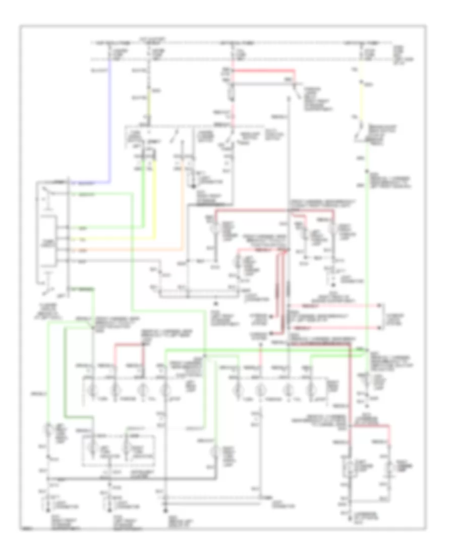
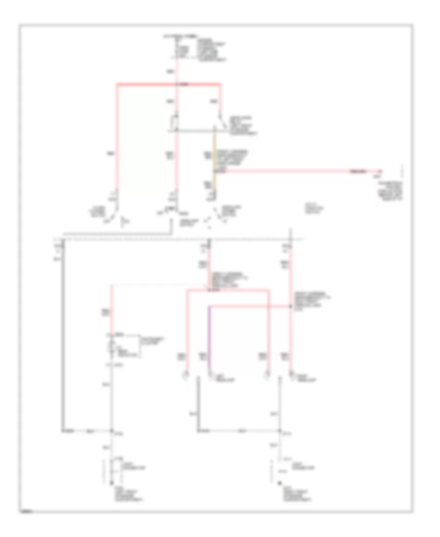
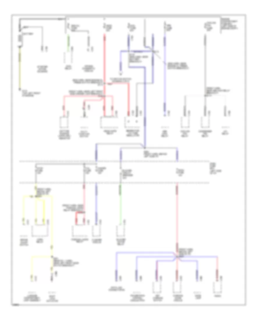
AIR CONDITIONING
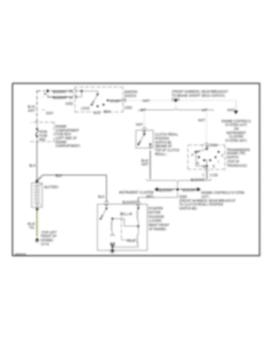
A/C Wiring Diagram for Ford Aspire 1997
 https://portal-diagnostov.com/license.html
Automotive Electricians Portal FZCO
Automotive Electricians Portal FZCO
https://portal-diagnostov.com/license.html
https://portal-diagnostov.com/license.html
Automotive Electricians Portal FZCO
Automotive Electricians Portal FZCO
List of elements for A/C Wiring Diagram for Ford Aspire 1997:
- (front harn, near winshield wiper motor breakout)
- (instrument harn, near blower motor resistors breakout) s217
- (instrument harn, near heater- a/c control unit breakout)
- A/c compressor clutch
- A/c condenser fan switch (left front of engine)
- A/c evaporator de-icing switch (center of i/p)
- A/c pressure cutoff switch (left front
- A/c relay (center rear of engine compartment)
- A/c switch
- Blower c.b. 30a
- Blower motor
- Blower motor relay (left front of engine compartment)
- Blower motor resistors (behind right side of i/p)
- C226
- C227
- Compartment)
- Condenser fan motor
- Condenser fan relay (right front of engine compartment)
- Cooling fan fuse 30a
- Cooling fan motor
- Cooling fan relay (left front of engine compartment)
- Dash fuse box
- Engine compartment fuse box
- Engine fuse 10a
- G101 (right front of engine compartment)
- G101 (right front of engine compt)
- G203 (at right cowl)
- Heater- a/c control unit
- Hot at all times
- Hot in run
- Hot in run or start
- Interior lights system
- Junction connector
- Nca
- Of engine
- Off
- Pnk
- Powertrain control module (pcm) (behind left side of i/p)
- Red
- S113 (front harn, near abs main relay breakout)
- S115 (front harn, near abs main relay breakout)
- S117
- S119 (front harness, left side of eng compt)
- S143 (front harn, near right front side marker lamp breakout)
- S144 (front harn, near cooling fan motor breakout)
- S212 (instrument harn, near right cowl)
- S218
- S246 (front harn, behind left side of i/p)
- Wiper fuse 20a
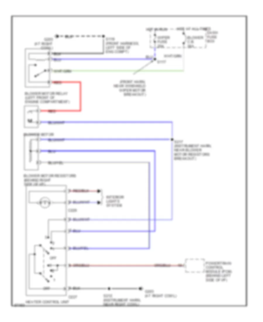
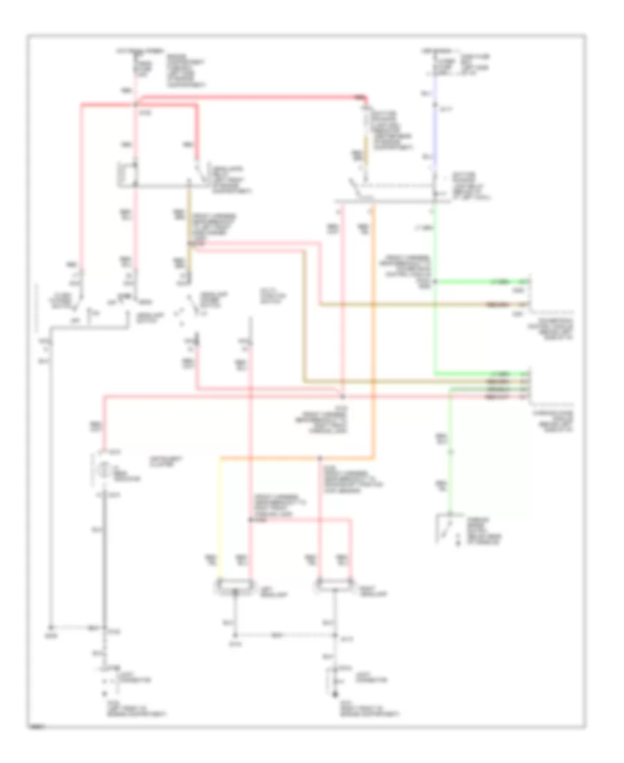
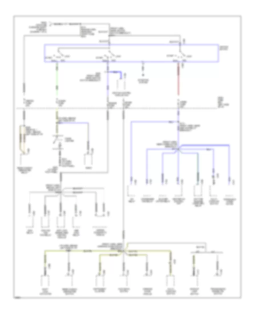
Heater Wiring Diagram for Ford Aspire 1997
List of elements for Heater Wiring Diagram for Ford Aspire 1997:
- (front harn, near winshield wiper motor breakout)
- Blower c.b. 30a
- Blower motor
- Blower motor relay (left front of engine compartment)
- Blower motor resistors (behind right side of i/p)
- C226
- C227
- Dash fuse box
- G203 (at right cowl)
- Heater control unit
- Hot at all times
- Hot in run
- Interior lights system
- Off
- Powertrain control module (pcm) (behind left side of i/p)
- Red
- S117
- S119 (front harness, left side of eng compt)
- S212 (instrument harn, near right cowl)
- S217 (instrument harn, near blower motor resistors breakout)
- Wiper fuse 20a
ANTI-LOCK BRAKES
Anti-lock Brake Wiring Diagrams for Ford Aspire 1997
List of elements for Anti-lock Brake Wiring Diagrams for Ford Aspire 1997:
- rt rear brake sensor
- (front harness, near break-out to abs main relay) s116
- Abs fuse 60a
- Abs ind ctrl
- Abs main relay (left rear of engine compartment)
- Anti-lock brake (abs) control module (behind left side of i/p)
- Anti-lock brake (abs) hydraulic actuator unit (lower left front of engine compt)
- Anti-lock brake indicator
- Brake on/off switch (top of brake pedal)
- Brake sw input
- C138
- C139
- C209
- C219
- C220
- Dash fuse box
- Data link connector (left side of engine compartment)
- Dlc
- Engine compartment fuse box
- Engine fuse 10a
- Fail safe relay
- Fail safe rly ctrl
- G100 (left front of engine compartment)
- G202 (left side of i/p)
- Ground
- Hot at all times
- Hot in run or start
- Hydraulic pump motor
- Instrument cluster
- J/c
- L fnt brake sensor
- L fnt sol ctrl
- L rear brake sensor
- L rear sol ctrl
- Left front brake sensor
- Left front solenoid
- Left rear brake sensor
- Left rear solenoid
- Meter fuse 15a
- Nca
- Power
- Pump motor relay
- Pump mtr relay
- Pump mtr rly ctrl
- Red
- Right front brake sensor
- Right front solenoid
- Right rear brake sensor
- Right rear solenoid
- Rt fnt brake sensor
- Rt frt sol ctrl
- Rt rear brake sensor
- Rt rear sol cntrl
- S122
- S130 (front harness, near breakout to left forward crash sensor)
- S142
- S202
- S203 (front harness, near breakout to pcm)
- S204
- S214 (front harness, near breakout to instrument cluster)
- S243 (front harness, near breakout to anti-lock brake control module)
- S246
- Stop fuse 15a
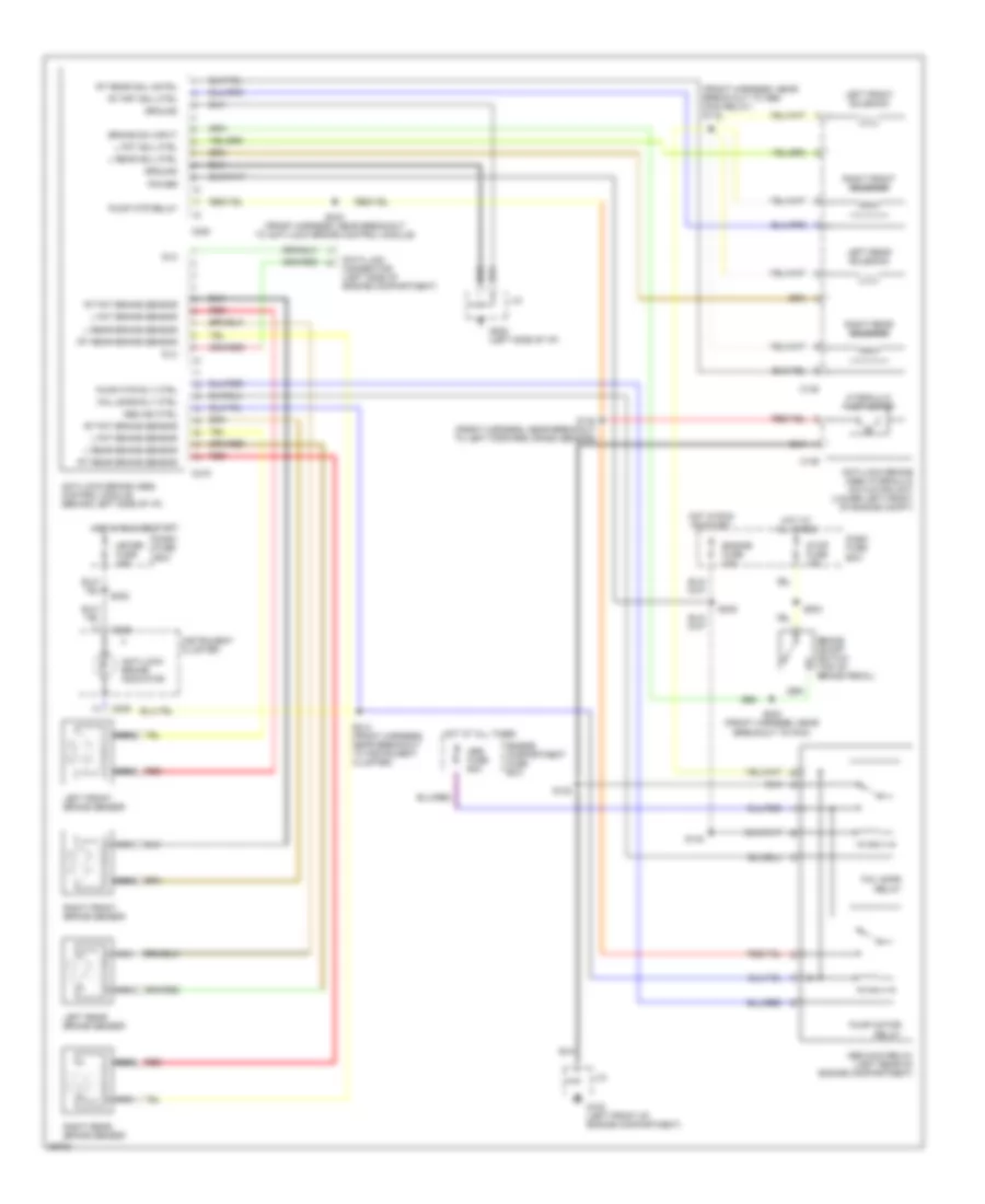
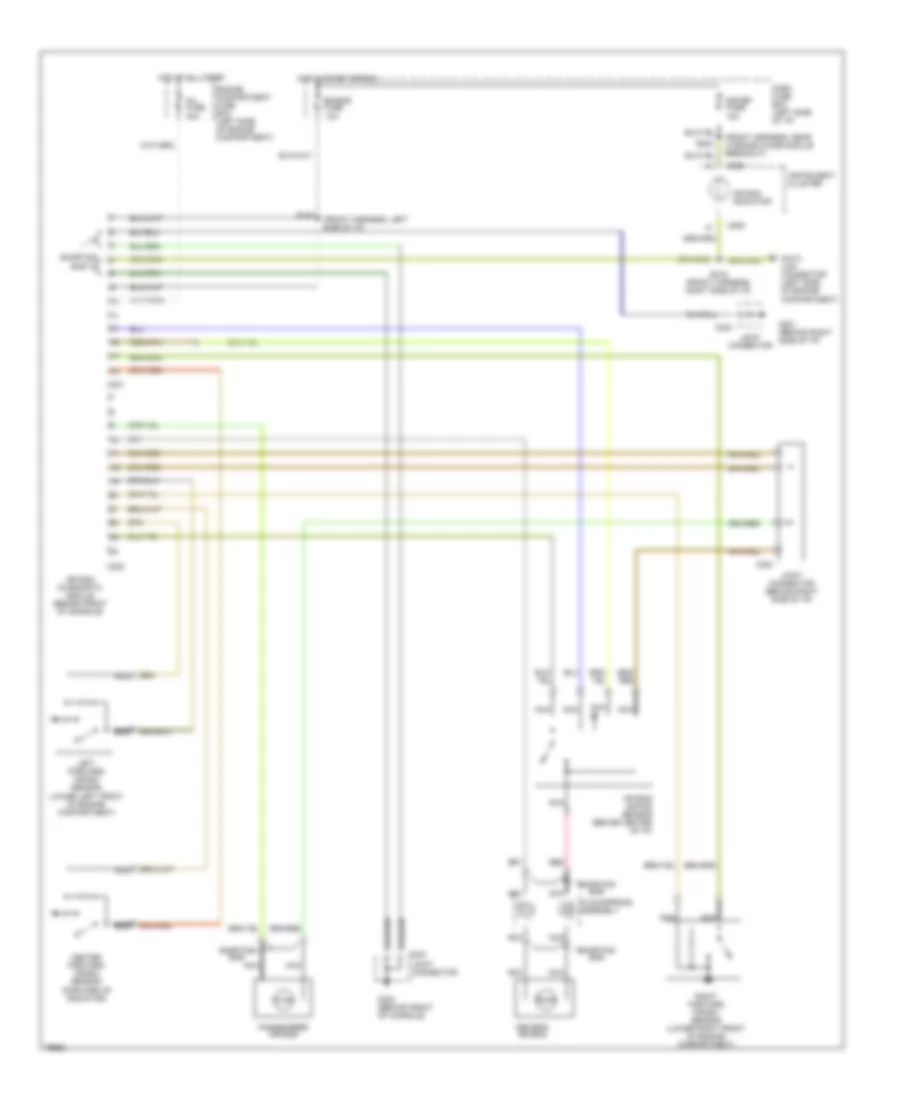
COMPUTER DATA LINES
Computer Data Lines for Ford Aspire 1997
List of elements for Computer Data Lines for Ford Aspire 1997:
- (engine harness, near breakout to back-up lamp switch) s111
- (front harness, near breakout behind right side of i/p) s216
- (front harness, near breakout to brake on-off (boo) switch) s250
- (front harness, near breakout to left front of engine compt.) s102
- (injector harness, near breakout to top right side of engine) s103
- (left side of engine compartment) data link connector (dlc) #1
- (left side of engine compt.)
- (lower center of i/p) data link connector (dlc) #2
- (not used)
- Air bag diagnostic module (behind front of console)
- Anti-lock brake (abs) control module (behind left side of i/p)
- Breakout to ground (g201), behind i/p at right cowl)
- C109
- C111
- C118
- C120
- C200
- C201
- C207
- C209
- C224
- Canister purge (canp) solenoid (top left side of engine)
- Clockspring assembly (top of steering column)
- Dash fuse box (left side of i/p)
- Dlc
- Egr control solenoid (center rear of eng compt)
- Egr vent solenoid (center rear of eng compt)
- Fpr
- Fuel injectors
- Fuel pump relay (behind i/p, at left cowl)
- G100 (left front of engine compt.)
- G101 (right front of engine compartment)
- G101 (right front of engine compt.)
- G102
- G302 (behind front of console)
- Horn relay (behind i/p, at left cowl)
- Hot at all times
- Idle air control (iac) valve (top left rear of engine)
- Ignition control (icm) shield
- Ignition control module (icm) (left side of eng compt)
- Instrument cluster
- J/c
- Main relay (behind i/p, at left cowl)
- Mass air flow (maf) sensor (in air intake assembly)
- Nca
- No.1
- No.2
- No.3
- No.4
- Pnk
- Powertrain control module (behind left side of i/p)
- Red
- Room fuse 10a
- S104 (engine harness, near breakout to pcm)
- S119 (front harness, near breakout to left side of engine compt.)
- S126 (engine harness, near breakout on top left side of engine)
- S132 (front harness, near breakout to abs main relay)
- S143
- S200
- S232
- S248 (front harness, near breakout to pcm)
- S249 front harness, near breakout to brake on-off (boo) switch)
- Shorting bar
- Vpwr
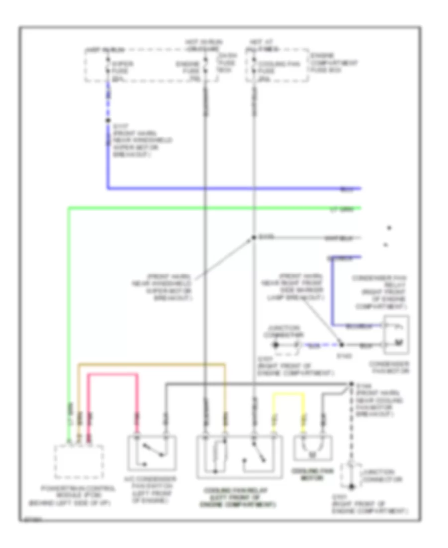
COOLING FAN
Cooling Fan Wiring Diagram for Ford Aspire 1997
List of elements for Cooling Fan Wiring Diagram for Ford Aspire 1997:
- (behind left side of i/p)
- (front harn, near right front side marker lamp breakout)
- (front harn, near windshield wiper motor breakout)
- (left front of (left front of (left front of (left front of
- A/c condenser
- Condenser fan motor
- Condenser fan relay (right front of engine compartment)
- Cooling fan cooling fan cooling fan cooling fan motor motor motor motor
- Cooling fan fuse 30a
- Cooling fan relay cooling fan relay cooling fan relay cooling fan relay
- Dash fuse box
- Engine compartment fuse box
- Engine compartment) engine compartment) engine compartment) engine compartment)
- Engine fuse 10a
- Fan switch (left front of engine)
- G101 (right front of engine compartment)
- Hot at all times
- Hot in run
- Hot in run or start
- Junction connector
- Pnk
- Pnk pnk pnk pnk
- Powertrain control module (pcm)
- S115
- S117 (front harn, near windshield wiper motor breakout)
- S143
- S144 (front harn, near cooling fan motor breakout)
- Wiper fuse 20a
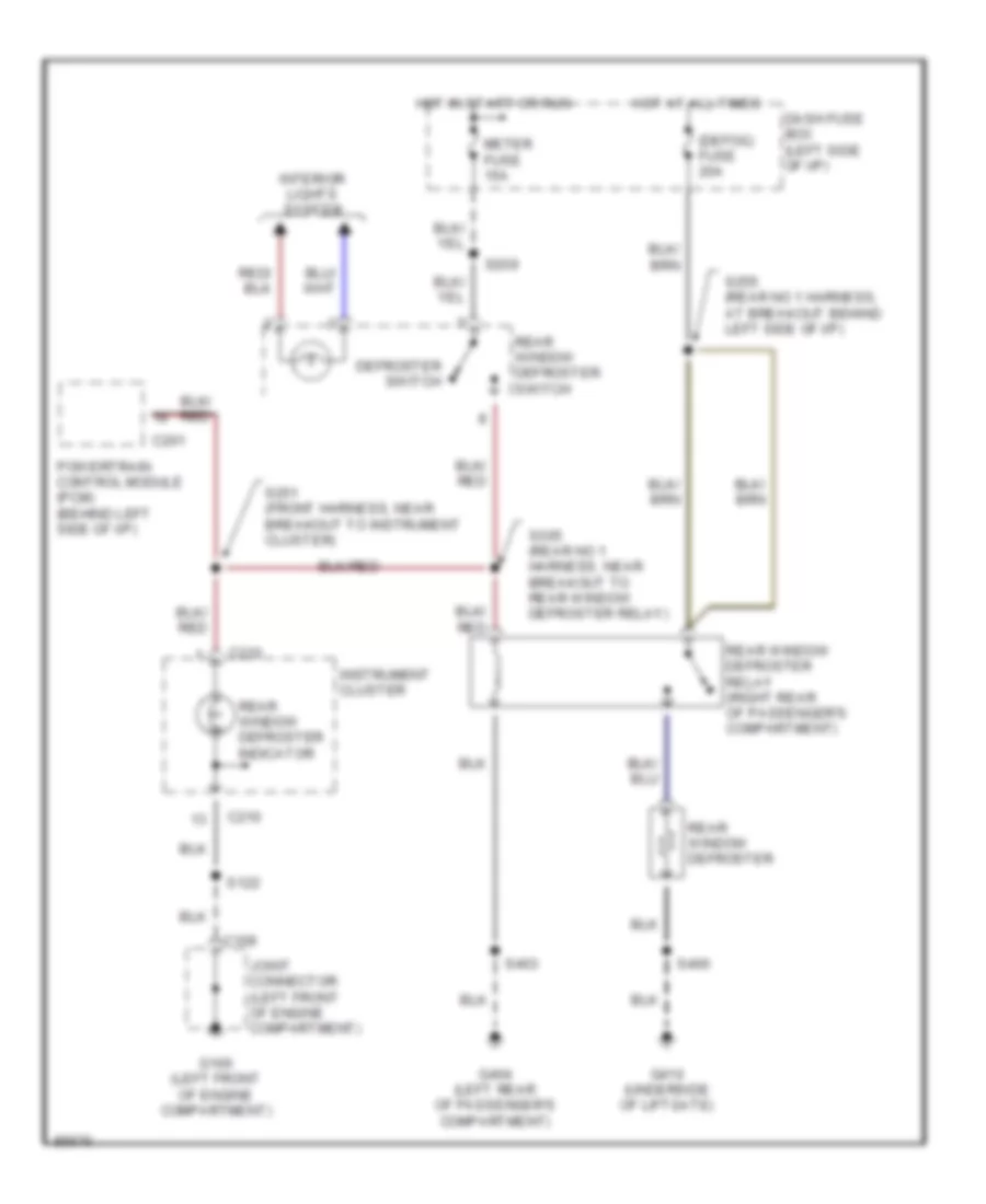
DEFOGGERS
Defogger Wiring Diagram for Ford Aspire 1997
List of elements for Defogger Wiring Diagram for Ford Aspire 1997:
- (defog) fuse 20a
- C109
- C201
- C210
- Dash fuse box (left side of i/p)
- Defroster switch
- G100 (left front of engine compartment)
- G404 (left rear of passenger's compartment)
- G410 (underside of liftgate)
- Hot at all times
- Hot in start or run
- Instrument cluster
- Interior lights system
- Joint connector (left front of engine compartment)
- Meter fuse 15a
- Powertrain control module (pcm) (behind left side of i/p)
- Rear window defroster
- Rear window defroster indicator
- Rear window defroster relay (right rear of passenger's compartment)
- Rear window defroster switch
- S122
- S209
- S251 (front harness, near breakout to instrument cluster)
- S255 (rear no 1 harness, at breakout behind left side of i/p)
- S305 (rear no 1 harness, near breakout to rear window defroster relay)
- S400
- S403
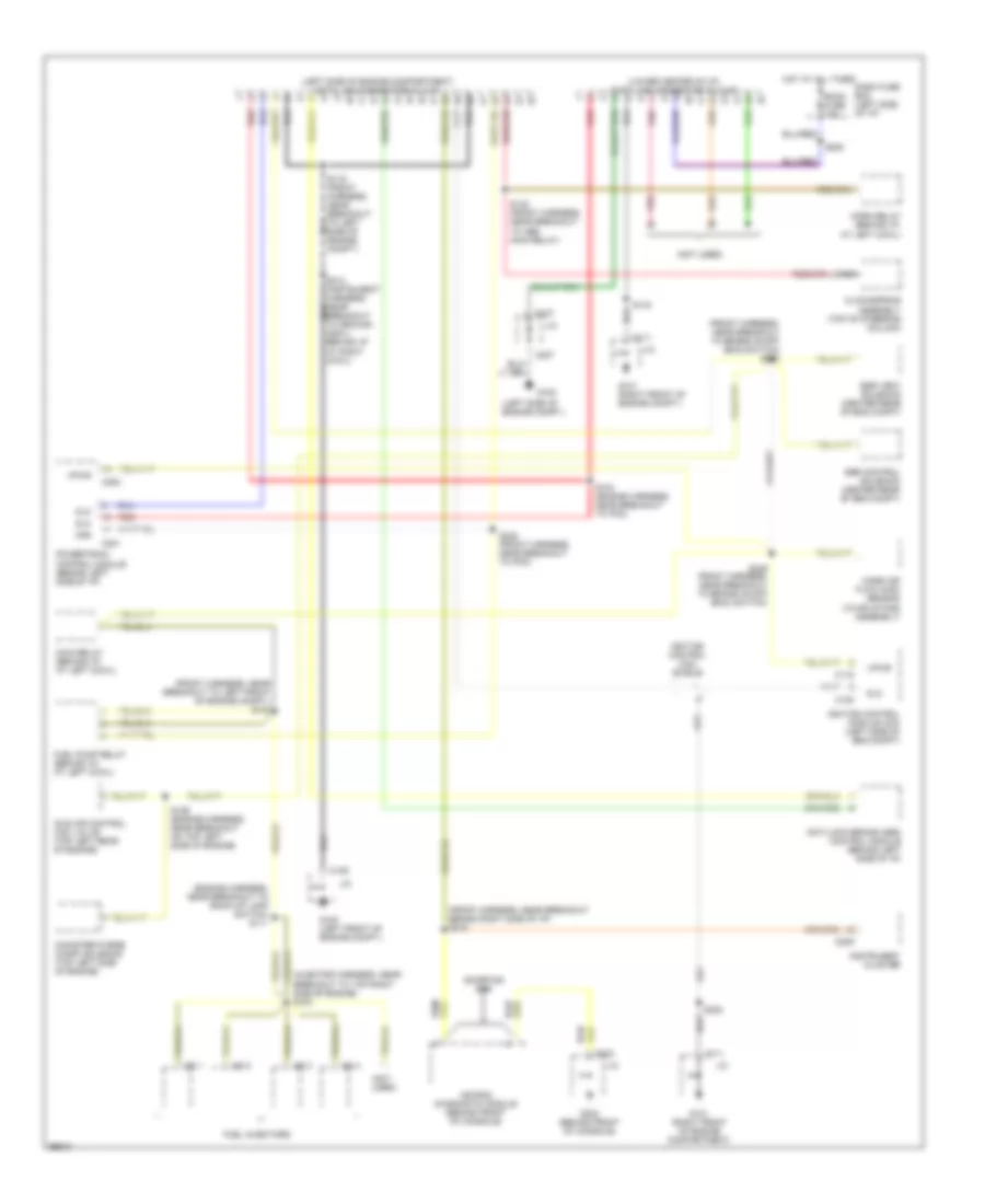
ENGINE PERFORMANCE
1.3L
1.3L, Engine Performance Wiring Diagrams (1 of 2) for Ford Aspire 1997
List of elements for 1.3L, Engine Performance Wiring Diagrams (1 of 2) for Ford Aspire 1997:
- (a/t only) psp
- (behind left side of dash) powertrain control module (pcm)
- (eng harness, left front of eng compt)
- (engine harness, near breakout to pcm conn)
- (front harness, near break- out to left side marker lamp)
- (front harness, near break- out to right side marker lp)
- (front harness, near breakout to pcm conn)
- (injector harness, near inj 4 breakout)
- (left side of engine compt)
- (top right side of engine)
- A/t
- Acc
- Acr
- Air conditioning system
- Blmt
- Boo
- Brake on/off (boo) switch (behind dash, top of brake pedal)
- C200
- C201
- C209
- C210
- C257
- Canp
- Ccps
- Cfan
- Cfr
- Cid signal
- Ckp
- Cooling fan system
- Dash fuse box
- Data link connector (dlc) #1 (left side of engine compartment)
- Data link connector (dlc) #2 (left side of eng compt)
- Def
- Defogger system
- Dlc #1
- Dlc #2
- Drl
- Ect
- Egr boost sens
- Egr valve position sensor
- Egrc
- Egrv
- Engine coolant temperature (ect) sensor (top right front of engine)
- Engine fuse 10a
- Evp
- Fpr
- G100 (left front of engine compt)
- G102
- Gnd
- Hdlr
- Head- lights system
- Headlights system
- Hot at all times
- Hot in start or run
- Iac
- Iat
- Idl
- Idle switch (top of engine)
- Ignition switch
- Inj1
- Inj2
- Inj3
- Inj4
- Instrument panel
- Intake air temperature (iat) sensor (right side of engine compartment in air intake)
- Kapwr
- Lock
- M/t
- Maf
- Malfunction indicator lamp
- Meter fuse 15a
- Mil
- Off
- Oxy sens o2s
- Pnk
- Pnp/cpp
- Power steering pressure (psp) switch (lower right front of engine compt)
- Rear h02s
- Rear ho2s
- Red
- Room fuse 10a
- Run
- S104
- S107
- S108
- S109
- S121
- S122
- S127
- S137
- S138
- S200
- S202
- S203 (front harness, near breakout to pcm conn)
- S204
- S246
- S248
- Sigrtn
- Spout
- Start
- Starting system
- Starting system (transmission range switch)
- Stop fuse 15a
- Throttle position (tp) sensor (top rear of engine, on throttle body)
- Vpwr
- Vref
- Vss
- Vst
1.3L, Engine Performance Wiring Diagrams (2 of 2) for Ford Aspire 1997
List of elements for 1.3L, Engine Performance Wiring Diagrams (2 of 2) for Ford Aspire 1997:
- (behind left side of i/p)
- (behnd dash, at left cowl)
- (engine harness, near breakout to backup lp sw)
- (engine harness, top left side of engine)
- (front harness, near breakout to boo switch)
- (injector harness, top right side of engine)
- (not
- (right side of engine)
- (top left rear of engine compt)
- (top right side of engine)
- A/c condenser fan switch (left front of engine)
- C108
- Canister purge (canp) solenoid (top left side of engine)
- Cid
- Ckp
- Clutch pedal position (cpp) switch #1 (top of clutch pedal)
- Crankshaft position (ckp) sensor (lower right
- Dlc
- Egi inj fuse 30a
- Egr boost sensor
- Egr control solenoid (center rear of engine compartment)
- Egr vent solenoid (rear center of engine compartment)
- Engine compartment fuse box
- Engine compt)
- Front of engine)
- Fuel injector no.1
- Fuel injector no.2
- Fuel injector no.3
- Fuel injector no.4
- Fuel pump relay
- Fuel pump/ fuel gauge sender (below rear seat)
- G100 (left front of engine compartment)
- G100 (left front of engine compt)
- G101 (right front of engine compt)
- G102 (left side of engine compt)
- G110 (top left front of engine)
- G202 (left side of i/p)
- Ground
- Hot at all times
- Idle air control (iac) valve (top left rear of engine)
- Ignition
- Ignition control module (icm) (part of distributor assembly)
- Inertia fuel shutoff (ifs) switch (left front of passenger's compartment
- Joint connector c207
- Main relay (behnd dash, at left cowl)
- Mass air flow (maf) sensor (right side of engine compt in air intake)
- Nca
- Oxygen sensor (o2s) (in exhaust manifold)
- Park/neutral position switch (top of transaxle)
- Pnk
- Rear heated oxygen sensor (ho2s)
- S100
- S102
- S103
- S106
- S111
- S122
- S126
- S131
- S143
- S232
- S237
- S249
- S250
- S253 (front harn, near pcm conn breakout)
- Spout
- Used)
- Vpwr
EXTERIOR LIGHTS
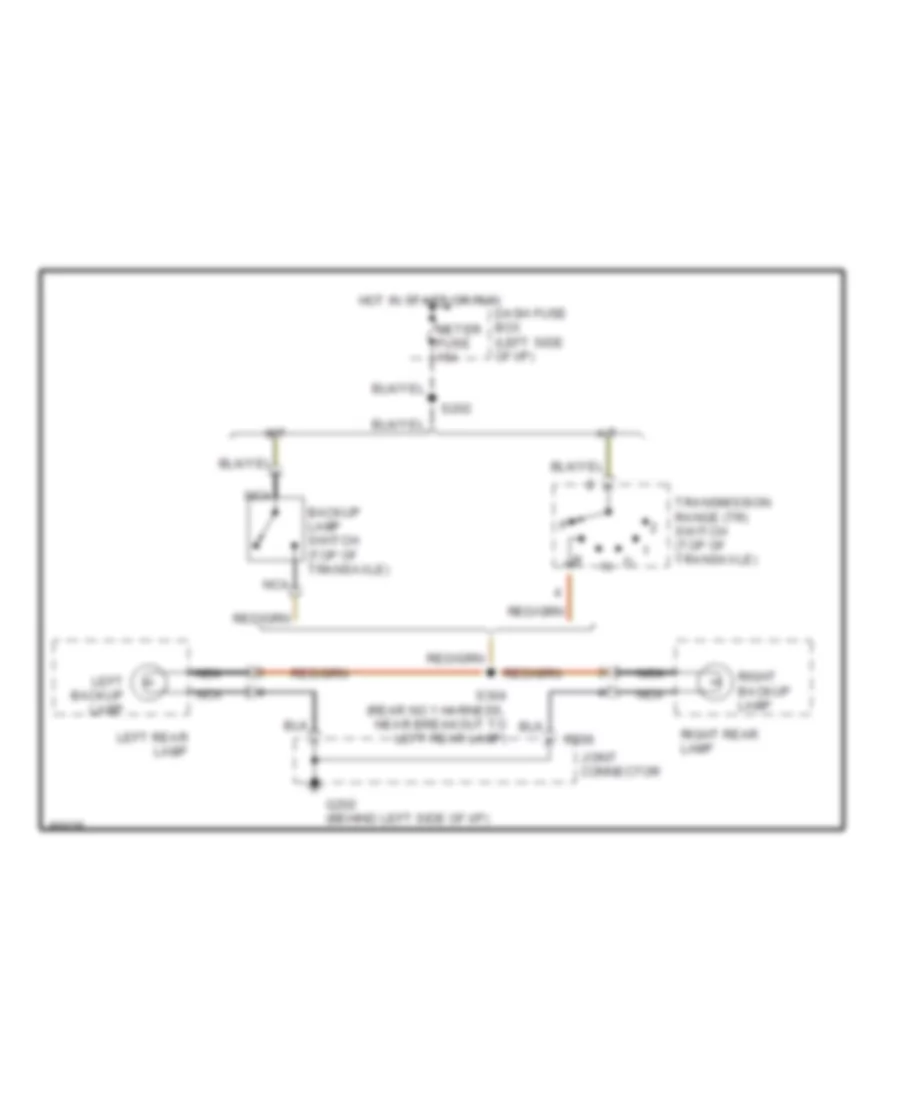
Back-up Lamps Wiring Diagram for Ford Aspire 1997
List of elements for Back-up Lamps Wiring Diagram for Ford Aspire 1997:
- A/t
- Backup lamp switch (top of transaxle)
- C206
- Dash fuse box (left side of i/p)
- G202 (behind left side of i/p)
- Hot in start or run
- Joint connector
- Left backup lamp
- Left rear lamp
- M/t
- Meter fuse 15a
- Nca
- Right backup lamp
- Right rear lamp
- S202
- S304 (rear no 1 harness, near breakout to left rear lamp)
- Transmission range (tr) switch (top of transaxle)
Exterior Lamps Wiring Diagram for Ford Aspire 1997
List of elements for Exterior Lamps Wiring Diagram for Ford Aspire 1997:
- (front harness, near break-out to multi- function switch) s242
- (front harness, near breakout to right front parking light) s133
- (rear no 1 harness, near break-out to left rear lamp) s406
- (underside of liftgate) g410
- Brake on/off (boo) switch (top of brake pedal)
- C109
- C111
- C206
- C209
- C210
- Dash fuse box (left side of i/p)
- Flasher module (behind i/p, at left cowl)
- G100 (left front of engine compartment)
- G101 (right front of engine compartment)
- G202 (behind left side of i/p)
- G410 (underside of liftgate)
- Hazard flasher switch
- Hazard fuse 15a
- Head
- Headlamp switch
- High mount stop lamp
- Hot at all times
- Hot in start or run
- Instrument cluster
- Interior lights system
- Joint connector
- Left
- Left front parking lamp
- Left front side marker lamp
- Left front turn signal lamp
- Left license lamp
- Left rear lamp
- Left turn indicator
- Meter fuse 15a
- Multi- function switch
- Nca
- Off
- Park
- Parking
- Parking lamps relay (right front of engine compartment)
- Rear no. 3 harness, near breakout in liftgate, to license lamps) s404
- Red
- Red s139
- Right
- Right front parking lamp
- Right front side marker lamp
- Right front turn signal lamp
- Right license license lamp lamp
- Right rear lamp
- Right turn indicator
- S101
- S110
- S119
- S122
- S143
- S144
- S202
- S204
- S224 (i/p harness, near breakout at left side of i/p)
- S229 (front harness, near breakout to multi- function sw)
- S239
- S300 (rear no. 1 harness, near breakout to left front door sw)
- S303 (rear no 1 harness, near break- out to parking brake switch)
- S400
- S407 (rear no. 1 harness, near breakout to inertia fuel shut-off (ifs) switch)
- Stop
- Stop fuse 15a
- Tail
- Tail fuse 15a
- Timer circuit
- Turn
- Turn signal switch
- Warning system
GROUND DISTRIBUTION
Ground Distribution Wiring Diagram (1 of 2) for Ford Aspire 1997
List of elements for Ground Distribution Wiring Diagram (1 of 2) for Ford Aspire 1997:
- (front harness, near right front side marker light breakout) s143
- (not used)
- A/c condenser fan switch
- Abs main relay
- Anti-lock brake (abs) hydraulic actuator unit
- Blower motor relay
- Brake fluid level switch
- C109
- C111
- C237
- C259
- Cigar lighter
- Clutch pedal position (ccp) switch #1
- Condenser fan motor
- Condenser fan switch
- Cooling fan motor
- Data link connector (dlc) no. 2
- Data link connector no 1 (dlc)
- Flasher module
- G100 (left front of engine compartment)
- G101 (right front of engine compartment)
- G201 (behind i/p, at right cowl)
- Heater- a/c control unit
- Ignition control module (icm) shield
- Instrument cluster
- Instrument panel dimming rheostat
- Joint connector
- Left front parking lamp
- Left front side marker lamp
- Left front turn signal lamp
- Left headlamp
- Main relay
- Multi- function switch
- Rear heated oxygen sensor (ho2s)
- Right front parking lamp
- Right front side marker lamp
- Right front turn signal lamp
- Right headlamp
- S101 (front harness, near flasher module breakout)
- S110 (front harness, near right front brake sensor breakout)
- S119 (front harness, left side of engine compt)
- S122 (front harness, near anti-lock brake control module breakout)
- S144 (front harness, near cooling fan motor breakout)
- To g202 (diagram 2 of 2)
- Warning chime module
- Windshield washer pump
Ground Distribution Wiring Diagram (2 of 2) for Ford Aspire 1997
List of elements for Ground Distribution Wiring Diagram (2 of 2) for Ford Aspire 1997:
- (diagram 1 of 2) from g101
- (engine harness, near break-out to park/neutral position switch) s131
- (front harness, near break-out to clutch pedal position sw no. 2)
- (not used)
- (rear no. 3 harness, near break-out to liftgate switch) s400
- 3 passenger
- 5 passenger
- Air bag diagnostic module
- Anti- lock brake (abs) control module
- C118
- C200
- C206
- C207
- C208
- C221
- C223
- C224
- C259
- Crankshaft position sensor shield
- Data link connector (dlc) no. 2
- G102 (left side of engine compartment)
- G110 (top left front of engine)
- G201 (behind right side of i/p)
- G202 (behind left side of i/p)
- G202 (left side of i/p)
- G302 (behind front of console)
- G304 (left rear of passenger compartment
- G306 (center rear of passenger compartment)
- G406 (underside of liftgate)
- High mount stop lamp
- Ignition control module (icm)
- Inertia fuel shutoff (ifs) switch
- Joint connector
- Left front brake sensor shield
- Left license lamp
- Left rear brake sensor shield
- Left rear lamp
- M/t only
- Mass air flow (maf) sensor
- Park range switch
- Park/ neutral position switch
- Power- train control module (pcm)
- Rear window defroster
- Rear window defroster relay
- Right front brake sensor shield
- Right license lamp
- Right rear brake sensor shield
- Right rear lamp
- S100 (no location available)
- S106 (front harness, near break-out to maf sensor)
- S233 (front harness, near break-out for clutch pedal position switch no. 2)
- S234
- S237 (front harness, at break-out to pcm)
- S403
- Seat belt switch
- Shift lock actuator
- Shorting connector
HEADLIGHTS
Headlight Wiring Diagram, with DRL for Ford Aspire 1997
List of elements for Headlight Wiring Diagram, with DRL for Ford Aspire 1997:
- (front harness, near breakout to left front side marker lamp) s105
- (front harness, near breakout to powertrain control module (pcm)) s252
- (front harness, near breakout to right front parking lamp) s124
- C109
- C111
- C200
- C201
- C210
- Dash fuse box (left side of i/p)
- Daytime running lamp (drl) resistor (center rear of engine compartment)
- Daytime running lamp relay (behind i/p, at left cowl)
- Engine compartment fuse box (left side of engine compartment)
- Flash- to-pass- switch
- G100 (left front of engine compartment)
- G101 (right front of engine compartment)
- Head
- Head fuse 30a
- Headlamp dimmer switch
- Headlamp switch
- Headlamps relay (left front of engine compartment)
- Hi beam indicator
- Hot at all times
- Hot in run
- Instrument cluster
- Joint connector
- Left headlamp
- Multi- function switch
- Nca
- Off
- Park
- Parking brake switch (below rear of console)
- Powertrain control module (behind left side of i/p)
- Red
- Right headlamp
- S110
- S117
- S120
- S122
- S123 (front harness, near breakout to, right front parking lamp)
- S128 (front harness, near breakout to crankshaft position (ckp) sensor)
- S144
- S239
- Warning chime module (behind left side of i/p)
- Wiper fuse 20a
Headlight Wiring Diagram, without DRL for Ford Aspire 1997
List of elements for Headlight Wiring Diagram, without DRL for Ford Aspire 1997:
- (front harness, near breakout to left front side marker lamp) s105
- (front harness, near breakout to right front parking lamp) s123
- (front harness, near breakout to right front parking lamp) s124
- C109
- C111
- C201
- C210
- Engine compartment fuse box (left side of engine compartment)
- Flash- to-pass- switch
- G100 (left front of engine compartment)
- G101 (right front of engine compartment)
- Head
- Head fuse 30a
- Headlamp dimmer switch
- Headlamp switch
- Headlamps relay (left front of engine compartment)
- Hi beam indicator
- Hot at all times
- Instrument cluster
- Joint connector
- Left headlamp
- Multi- function switch
- Nca
- Off
- Park
- Powertrain control module (pcm) (behind left side of i/p)
- Red
- Right headlamp
- S110
- S120
- S122
- S144
- S239
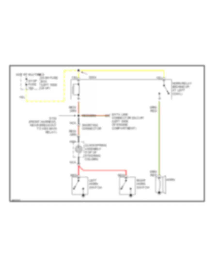
HORN
Horn Wiring Diagram for Ford Aspire 1997
List of elements for Horn Wiring Diagram for Ford Aspire 1997:
- Clockspring assembly (top of steering column)
- Connector (dlc) #1 (left side of engine compartment)
- Dash fuse box (left side of i/p)
- Data link
- Horn
- Horn relay (behind i/p, at left cowl)
- Hot at all times
- Left horn switch
- Nca
- Red
- Right horn switch
- S132 (front harness, near breakout to abs main relay)
- S204
- Shorting connector
- Stop fuse 15a
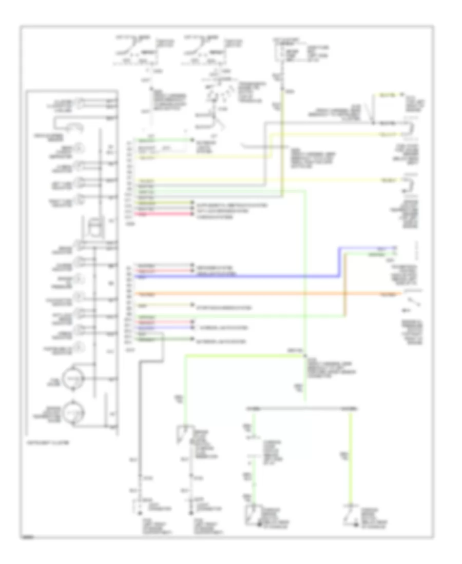
INSTRUMENT CLUSTER
Instrument Cluster Wiring Diagram for Ford Aspire 1997
List of elements for Instrument Cluster Wiring Diagram for Ford Aspire 1997:
- (a/t)
- (m/t)
- A/t
- A10
- A11
- A12
- A13
- A14
- Acc
- Airbag indicator
- Anti-lock brake indicator
- Anti-lock brakes system
- B10
- B11
- B12
- B13
- B14
- Brake fluid level switch (in brake fluid reservoir)
- Brake indicator
- C109
- C129
- C201
- C202
- C209
- C210
- Charge indicator
- Cluster illumination (4 bulbs)
- Dash fuse box (left side of i/p)
- Defogger system
- Engine coolant temperature gauge
- Engine coolant temperature sender (top left side of engine)
- Engine oil pressure
- Engine oil pressure switch (top right front of engine)
- Exterior lights system
- Fasten belts indicator
- Fuel gauge
- Fuel pump/ fuel gauge sender (below rear seat)
- G100 (left front of engine compartment)
- G110 (top left front of engine)
- Headlights system
- Hi beam indicator
- Hot at all times
- Hot in start or run
- Ignition switch
- Instrument cluster
- Interior lights system
- Joint connector
- Left turn indicator
- Lock
- M/t
- Malfunction indicator
- Meter fuse 15a
- Parking brake switch (below rear of console)
- Pnk
- Powertrain control module (pcm) (behind left side of i/p)
- Rear window defroster
- Right turn indicator
- Run
- S122
- S129 (front harness, near breakout to instrument cluster)
- S135 (front harness, near breakout to left forward crash sensor connector)
- S202
- S205 (front harness, near breakout to brake on/off (boo) switch)
- S206 (front harness, near breakout to clutch pedal position (cpp) switch #2)
- Start
- Starting/charging system
- Transmission range (tr) switch (top of transaxle)
- Vehicle speed sensor
- W/ drl
- W/o drl
- Warning chime module (behind left side of i/p)
- Warning systems
INTERIOR LIGHTS
Interior Light Wiring Diagram for Ford Aspire 1997
List of elements for Interior Light Wiring Diagram for Ford Aspire 1997:
- (instrument harness, near breakout behind left side of i/p) s225
- (instrument harness, near breakout behind left side of i/p)
- C109
- C210
- C238
- Dash fuse box (left side of i/p)
- Dome lamp
- Door
- Exterior lights system
- G100 (left front of engine compartment)
- G201 (behind i/p, at right cowl)
- Head
- Headlamp switch
- Heater- a/c control unit
- Hot at all times
- Instrument cluster
- Instrument panel dimming rheostat
- Joint connector
- Left front door switch (in left "b" pillar)
- Liftgate switch (in liftgate)
- Luggage compartment lamp assembly
- Multi- function switch
- Nca
- Off
- Park
- Parking lamps relay (right front of engine compartment)
- Radio
- Rear window defroster switch
- Red
- Right front door switch (in right "b" pillar)
- Room fuse 10a
- S133 (front harness, near breakout to right front parking lamp)
- S139
- S200
- S212
- S221 (front harness, near breakout to multi-function switch)
- S224
- S239
- S242 (front harness, near breakout to multi-function switch)
- S301
- S302 (rear no. 1 harness, near breakout to left front door switch)
- S303 (rear no. 1 harness, near breakout to parking brake switch)
- Stop fuse 15a
- Tail fuse 15a
- Transmission range (tr) illumination (w/ a/t only)
- Warning chime module (behind left side of i/p)
POWER DISTRIBUTION
Power Distribution Wiring Diagram (1 of 2) for Ford Aspire 1997
List of elements for Power Distribution Wiring Diagram (1 of 2) for Ford Aspire 1997:
- (eng harn, near engine oil press switch breakout)
- (eng harn, near engine oil press switch breakout) s114
- (front harn, behind left side of i/p) s200
- (front harn, behind left side of i/p) s204
- (front harn, near abs main relay breakout) s115
- (front harn, near left front side marker lamp breakout) s120
- (front harn, near parking lamps relay breakout) s139
- A/c relay
- Abs fuse 60a
- Abs main relay
- Air bag diagnostic module
- Battery
- Blower circuit breaker 30a
- Blower motor relay
- Brake on/off switch
- C130
- C132
- C133
- C140
- C150
- C152
- C154
- C157
- C159
- C173
- C181
- C184
- C200
- C204
- C211
- C215
- C221
- C233
- C235
- C237
- C238
- C242
- C259
- C300
- C306
- C412
- Condenser fan relay
- Cooling fan fuse 30a
- Cooling fan relay
- Dash fuse box (left side of i/p)
- Data link connector #2
- Daytime running lamps (drl) resistor
- Dome lamp
- Egn inj fuse 30a
- Engine compartment fuse box (left side of engine compt)
- Flasher module
- G110 (top left front of engine)
- Generator/ voltage regulator
- Hazard fuse 15a
- Head fuse 30a
- Headlamps relay
- Horn relay
- Key warning switch
- Luggage compartment lamp assembly
- Main fuse 80a
- Main relay
- Multi- function switch
- Nca
- Parking lamps relay
- Powertrain control module (pcm)
- Radio
- Red
- Room fuse 10a
- S112
- S140 (eng harn, near battery breakout)
- S254 (front harn, behind left side i/p)
- S301 (rear no. 1 harn, near left front door switch breakout)
- Shift lock actuator
- Starter motor/ solenoid
- Stop fuse 15a
- Tail fuse 15a
- To ignition switch (diagram 2 of 2)
- Warning chime module
Power Distribution Wiring Diagram (2 of 2) for Ford Aspire 1997
List of elements for Power Distribution Wiring Diagram (2 of 2) for Ford Aspire 1997:
- (cigar) fuse 15a
- (defog) fuse 20a
- (front harn, behind left side of i/p) s246
- (front harn, near ignition switch breakout) s241
- (front harn, near warning chime module breakout) s202
- (front harn, near wiper motor breakout) s117
- (i/p harn, behind left side of i/p) s209
- (i/p harn, behind left side of i/p) s211
- A/c relay
- A/t
- Abs main relay
- Acc
- Air bag diagnostic module
- Anti-lock brake (abs) control module
- Backup lamp switch
- Blower motor relay
- C120
- C129
- C133
- C140
- C150
- C152
- C154
- C171
- C202
- C204
- C209
- C220
- C221
- C226
- C228
- C233
- C237
- C238
- C241
- C243
- C258
- C300
- C404
- Cigar lighter
- Condenser fan relay
- Cooling fan fan relay
- Dash fuse box (left side of i/p)
- Daytime running lamps (drl) relay
- Engine fuse 10a
- From main fuse in engine compt fuse box (diagram 1 of 2)
- G203 (at right kick panel)
- Heater-a/c control unit
- Ignition control module (icm)
- Ignition switch
- Instrument cluster
- Kick down switch
- Lock
- M/t
- Main relay
- Meter fuse 15a
- Multi- function switch
- Nca
- Radio
- Rear window defroster relay
- Rear window defroster switch
- Run
- S113 (front harn, near abs main relay breakout)
- S141 (engine harn, near eng compt fuse box)
- S208 (front harn, near ignition switch breakout)
- S212 (i/p harn, at right kick panel)
- Shift lock actuator
- Start
- Starting system
- Transmission range (tr) switch
- Warning chime module
- Windshield wiper motor
- Wiper fuse 20a
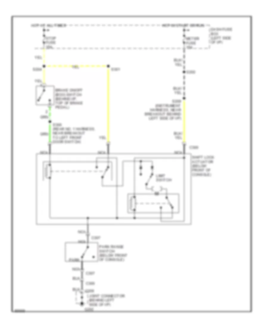
SHIFT INTERLOCKS
Shift Interlock Wiring Diagram for Ford Aspire 1997
List of elements for Shift Interlock Wiring Diagram for Ford Aspire 1997:
- Brake on/off (boo) switch (behind i/p, top of brake pedal)
- C206
- C300
- C307
- Dash fuse box (left side of i/p)
- G202
- Hot at all times
- Hot in start or run
- Joint connector (behind left side of i/p)
- Limit switch
- Meter fuse 15a
- Nca
- Park
- Park range switch (below front of console)
- S202
- S204
- S209 (instrument harness, near breakout behind left side of i/p)
- S300 (rear no. 1 harness, near breakout to left front door switch)
- S301
- Shift lock actuator (below front of console)
- Stop fuse 15a
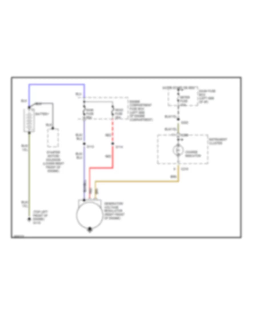
STARTING/CHARGING
Charging Wiring Diagram for Ford Aspire 1997
List of elements for Charging Wiring Diagram for Ford Aspire 1997:
- (top left front of engine) g110
- Battery
- C209
- C210
- Charge indicator
- Dash fuse box (left side of i/p)
- Engine compartment fuse box (left side of engine compartment)
- Generator/ voltage regulator (right front of engine)
- Head fuse 30a
- Hot in start or run
- Instrument cluster
- Main fuse 80a
- Meter fuse 15a
- Red
- S112
- S114
- S202
- Starter motor/ solenoid (lower right front of engine)
Starting Wiring Diagram for Ford Aspire 1997
List of elements for Starting Wiring Diagram for Ford Aspire 1997:
- (front harness, near breakout to brake on/off (boo) switch) s205
- (top left front of engine) g110
- A/t
- Acc
- Battery
- C129
- C202
- Clutch pedal position switch #2 (behind i/p, top of clutch pedal)
- Engine compartment fuse box (left side of engine compartment)
- Engine controls system (a/t)
- Engine controls system (a/t) or instrument cluster system (m/t)
- Hold
- Ignition switch
- Instrument cluster (m/t)
- Lock
- M/t
- Main fuse 80a
- Pull-in
- Run
- S206 (front harness, near breakout to clutch pedal position switch #2)
- S241
- Start
- Starter motor/ solenoid (lower right front of engine)
- Transmission range (tr) switch (top of transaxle)
SUPPLEMENTAL RESTRAINTS
Supplemental Restraint Wiring Diagram for Ford Aspire 1997
List of elements for Supplemental Restraint Wiring Diagram for Ford Aspire 1997:
- (front harness, left side of i/p)
- (front harness, near warning chime module breakout)
- Air bag diagnostic module (behind front of console)
- Air bag indicator
- Air bag safing sensor (behind center of i/p)
- Assembly
- C209
- C221
- C222
- C223
- C224
- Center forward crash sensor (forward of radiator)
- Clockspring
- Dash fuse box (left side of i/p)
- Data link connector (left side of engine compartment)
- Driver's air bag
- Engine compartment fuse box (left side of engine compartment)
- Engine fuse 10a
- G201 (behind right side of i/p)
- G302 (behind front of console)
- Hot at all times
- Hot in start or run
- Inj fuse 30a
- Instrument cluster
- Joint connector
- Joint connector (behind right side of i/p)
- Left forward crash sensor (lower left front of engine compartment)
- Meter fuse 15a
- Nca
- Passenger's air bag
- Red
- Right forward crash sensor (lower right front of engine compartment)
- S202
- S216 (front harness, right side of i/p)
- S246
- Shorting bar
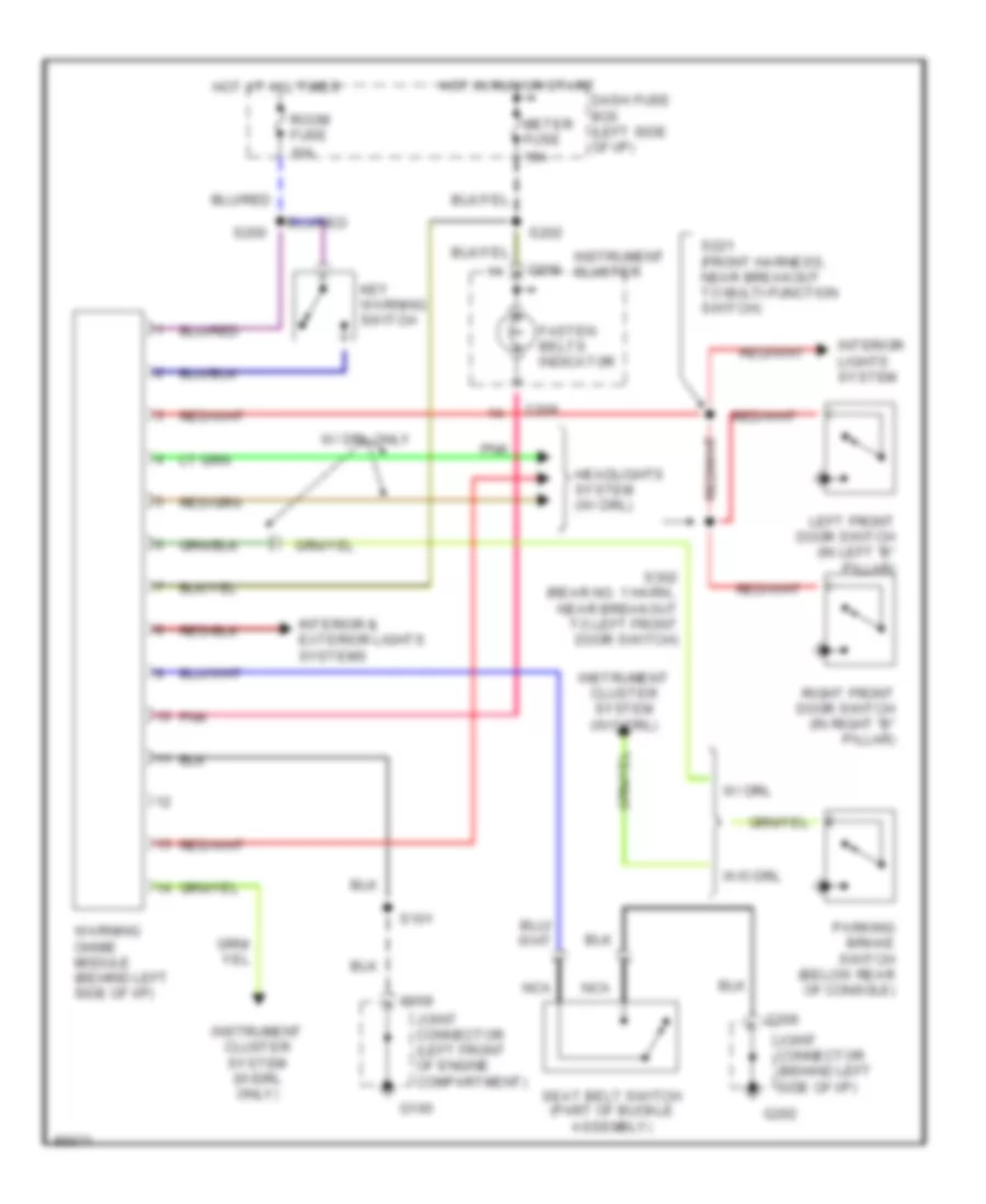
WARNING SYSTEMS
Warning System Wiring Diagrams for Ford Aspire 1997
List of elements for Warning System Wiring Diagrams for Ford Aspire 1997:
- C109
- C206
- C209
- Dash fuse box (left side of i/p)
- Fasten belts indicator
- G100
- G202
- Headlights system (w/ drl)
- Hot at all times
- Hot in run or start
- Instrument cluster
- Instrument cluster system (w/drl only)
- Instrument cluster system (w/o drl)
- Interior & exterior lights systems
- Interior lights system
- Joint connector (behind left side of i/p)
- Joint connector (left front of engine compartment)
- Key warning switch
- Left front door switch (in left "b" pillar)
- Meter fuse 15a
- Nca
- Parking brake switch (below rear of console)
- Pnk
- Right front door switch (in right "b" pillar)
- Room fuse 10a
- S101
- S200
- S202
- S221 (front harness, near breakout to multi-function switch)
- S302 (rear no. 1 harn., near breakout to left front door switch)
- Seat belt switch (part of buckle assembly)
- W/ drl
- W/ drl only
- W/o drl
- Warning chime module (behind left side of i/p)
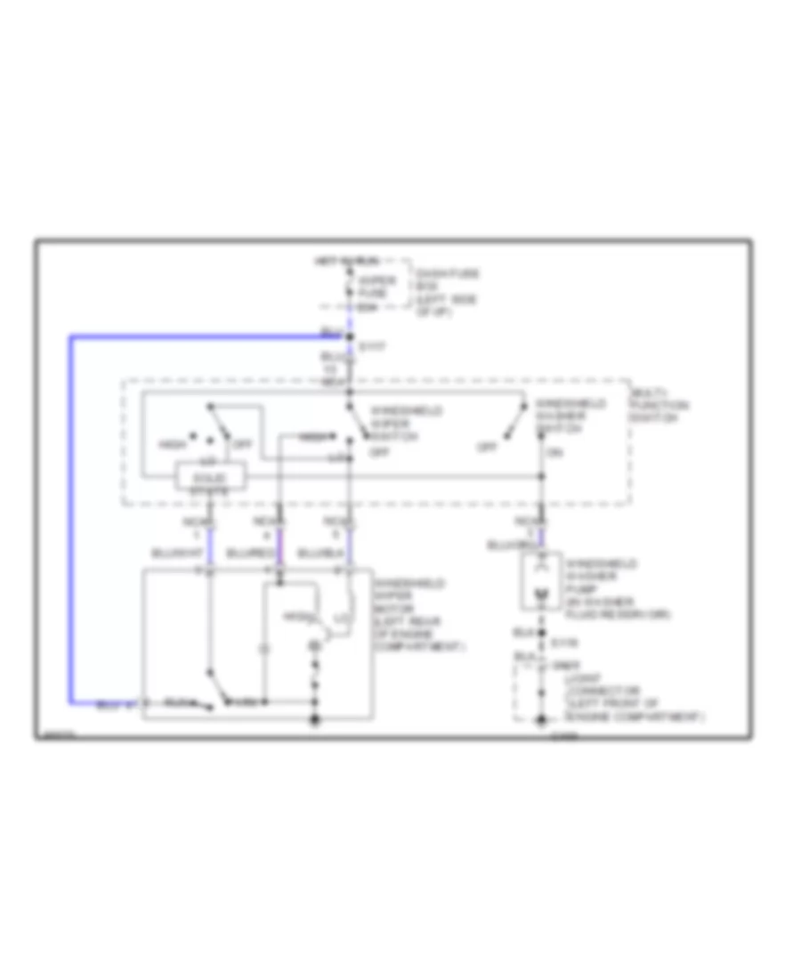
WIPER/WASHER
2-Speed Wiper/Washer Wiring Diagram for Ford Aspire 1997
List of elements for 2-Speed Wiper/Washer Wiring Diagram for Ford Aspire 1997:
- C109
- Dash fuse box (left side of i/p)
- G100
- High
- Hot in run
- Joint connector (left front of engine compartment)
- Multi- function switch
- Nca
- Off
- Park
- Run
- S117
- S119
- Solid state
- Windshield washer pump (in washer fluid reservoir)
- Windshield washer switch
- Windshield wiper motor (left rear of engine compartment)
- Windshield wiper switch
- Wiper fuse 20a
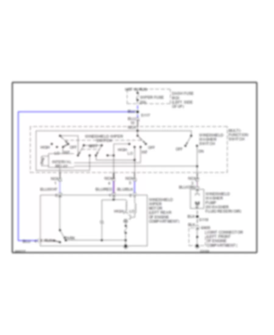
Interval Wiper/Washer Wiring Diagram for Ford Aspire 1997
List of elements for Interval Wiper/Washer Wiring Diagram for Ford Aspire 1997:
- C109
- Dash fuse box (left side of i/p)
- G100
- High
- Hot in run
- Int
- Interval relay
- Joint connector (left front of engine compartment)
- Mist
- Multi- function switch
- Nca
- Off
- Park
- Run
- S117
- S119
- Windshield washer pump (in washer fluid reservoir)
- Windshield washer switch
- Windshield wiper motor (left rear of engine compartment)
- Windshield wiper switch
- Wiper fuse 20a

 Čeština
 Dansk
Dansk Deutsch
 Ελληνικά
 English
 English
 Español
 Suomi
Suomi Français
 עברית
עברית Hrvatski
 Magyar
 Italiano
 日本語
日本語 한국어
한국어 Nederlands
 Polski
 Português
 Português
 Română
 Русский
 Slovenčina
 Slovenščina
 Svenska
 Türkçe
 中文 (中国)