AIR CONDITIONING
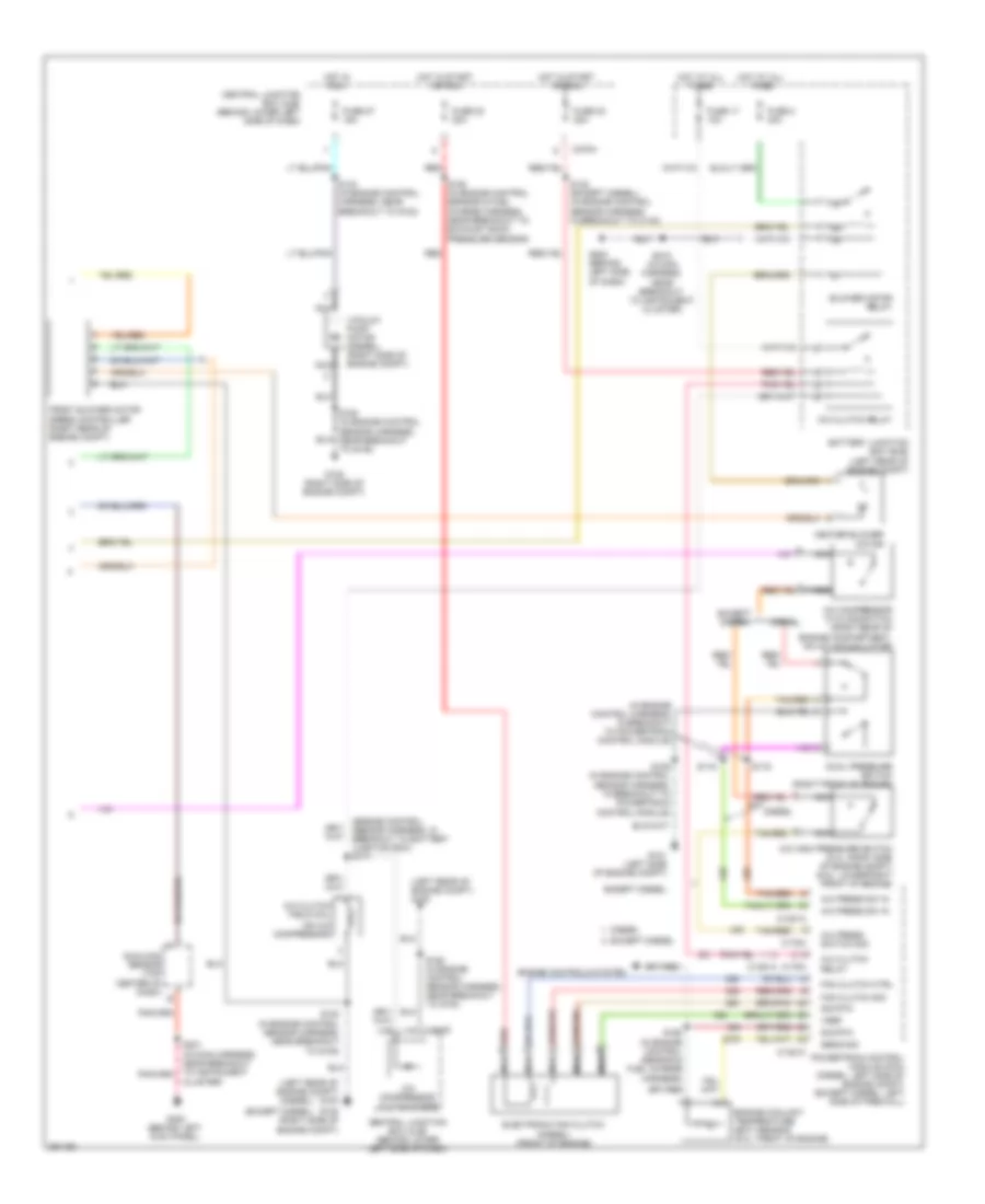
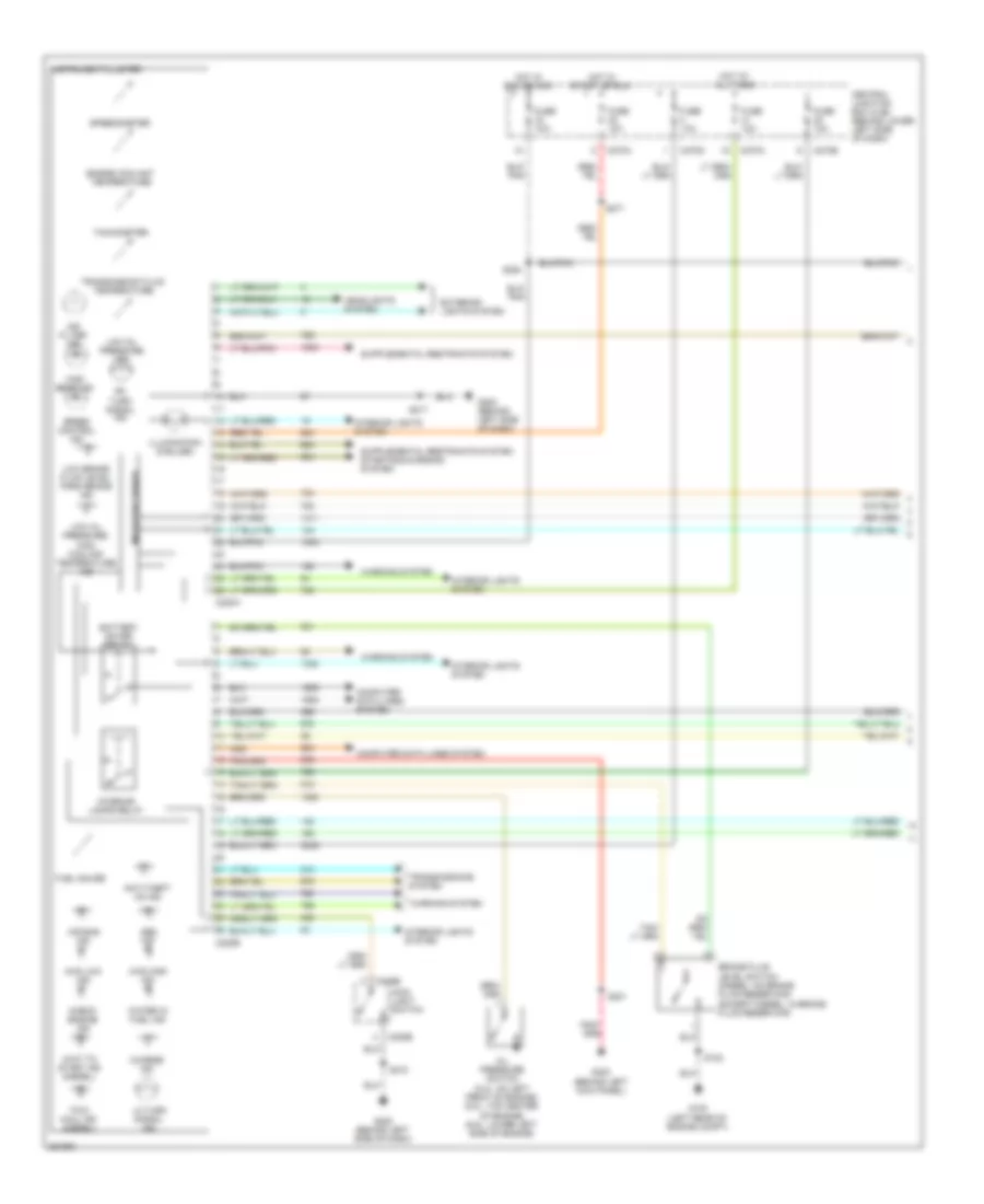
Automatic A/C Wiring Diagram (1 of 2) for Ford Cab & Chassis F350 Super Duty 2007
 https://portal-diagnostov.com/license.html
Automotive Electricians Portal FZCO
Automotive Electricians Portal FZCO
https://portal-diagnostov.com/license.html
https://portal-diagnostov.com/license.html
Automotive Electricians Portal FZCO
Automotive Electricians Portal FZCO
List of elements for Automatic A/C Wiring Diagram (1 of 2) for Ford Cab & Chassis F350 Super Duty 2007:
- A/c demand sig
- Air bag sliding contact (in steering column)
- Air temp dr sense +
- Air temp dr signal -
- Ambient air temperature sensor (except diesel: left front of engine compt)
- Ambient temp
- Blend door actuator +
- Blend door actuator -
- Blend door monitor
- Blower motor high
- Blower mtr rly ctrl
- Blower speed control signal return
- C228a
- C228b
- C270a
- Central junction box (cjb) (behind lower left side of dash)
- Computer data lines system
- Electronic automatic temperature control (eatc) module (behind center of dash)
- Fan speed (+)
- Fan speed (-)
- Fuse 10a
- Fuse 15a
- G202 (behind left side of dash)
- G300 (behind left kick panel)
- Harness, near breakout to instrument cluster)
- Hot at all times
- Hot in run
- Illumination
- In veh temp sensor
- In-vehicle temperature sensor (behind left side of dash)
- Interior lights system
- Logic gnd
- Nca
- Remote solenoid assembly (behind center of dash)
- Rest
- S148 (in main harness, near breakout to brake pressure transducer)
- S208 (in main harness, near breakout to instrument cluster)
- S218 (in main harness, near breakout to instrument cluster)
- S235 (in main harness, near breakout to auxiliary relay box 1)
- Sig return
- Solenoid 1 ctrl
- Solenoid 2 ctrl
- Solenoid 3 ctrl
- Solenoid 4 ctrl
- Solenoid 5 ctrl
- Solenoid assembly
- Speed controller
- Steering wheel controls
- Steering wheel radio switch
- Sunload sensor sig
- Temp (+)
- Temp (-)
- Temperature blend door actuator (behind right side of dash)
- Ubp diag
- Vpwr
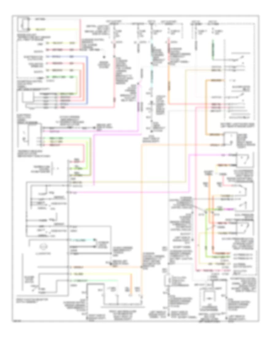
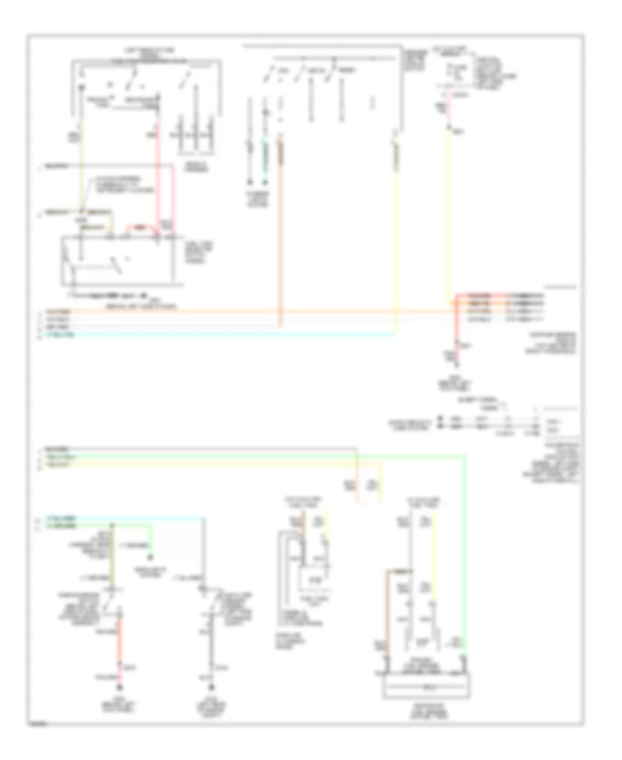
Automatic A/C Wiring Diagram (2 of 2) for Ford Cab & Chassis F350 Super Duty 2007
List of elements for Automatic A/C Wiring Diagram (2 of 2) for Ford Cab & Chassis F350 Super Duty 2007:
- (diesel)
- (engine control sensor harness, in breakout to battery junction box) s171
- (except diesel)
- (in engine control harness, in breakout to powertrain control module)
- (left rear of engine compt) g100
- (on a/c compressor)
- A/c clutch field coil
- A/c clutch relay
- A/c compressor clutch diode
- A/c compressor cycling switch (right rear of engine compartment, on a/c accumulator)
- A/c high pressure switch (5.4l: right side of engine compt) (6.8l: lower right front of engine)
- A/c press sw in
- A/c press switch sig
- Battery junction box (bjb) (left rear of engine compt)
- Blower motor relay
- C1381a
- C1381c
- C175a
- C270f
- C270h
- Central junction box (cjb) (behind lower left side of dash)
- Cluster)
- Diesel
- Dual pressure switch (right front of engine)
- Electronic fan clutch (diesel) (front of engine)
- Engine controls system
- Engine coolant temperature (ect) sensor (6.0l: front of engine)
- Except diesel
- Fan clutch ctrl
- Fan clutch sig
- Front blower motor speed controller (right rear of engine compt)
- Fuse 17 10a
- Fuse 2 40a
- Fuse 22 20a
- Fuse 23 20a
- Fuse 27 15a
- G101 (left side of engine compt)
- G108 (right side of engine compt)
- G202 (behind left side of dash)
- G300 (behind left kick panel)
- Heater blower motor
- Hot at all times
- Hot in run
- Hot in start or run
- Nca
- Powertrain control module (pcm) (diesel: left side of engine compt) (except diesel: left side of firewall)
- Red
- S106 (in engine control sensor harness, in breakout to powertrain control module)
- S116
- S119
- S122 (except diesel) (in engine control sensor harness, in breakout to c140)
- S124 (in engine control harness, near breakout to g100)
- S162 (in engine control sensor harness, near breakout to g100)
- S180 (in engine control sensor harness, near breakout to g108)
- S192 (in engine control sensor & fuel charge harness)
- S193 (in engine control sensor & fuel charge harness, near breakout to exhaust back pressure sensor)
- S218 (in main harness, near breakout to instrument cluster)
- Sens sig
- Sig rtn
- Sunload sensor (top center of dash)
- Tan/red
- Vacuum pump motor (diesel) (right side of engine compt)
- Vref
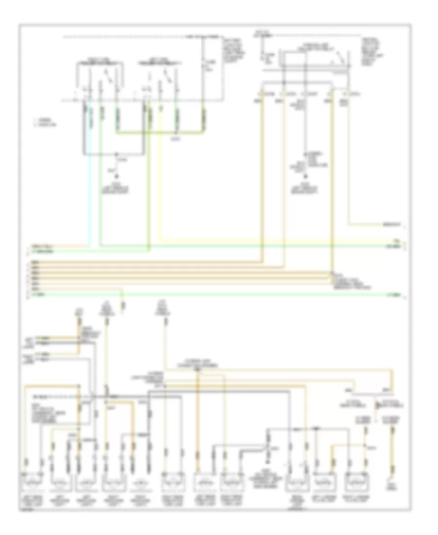
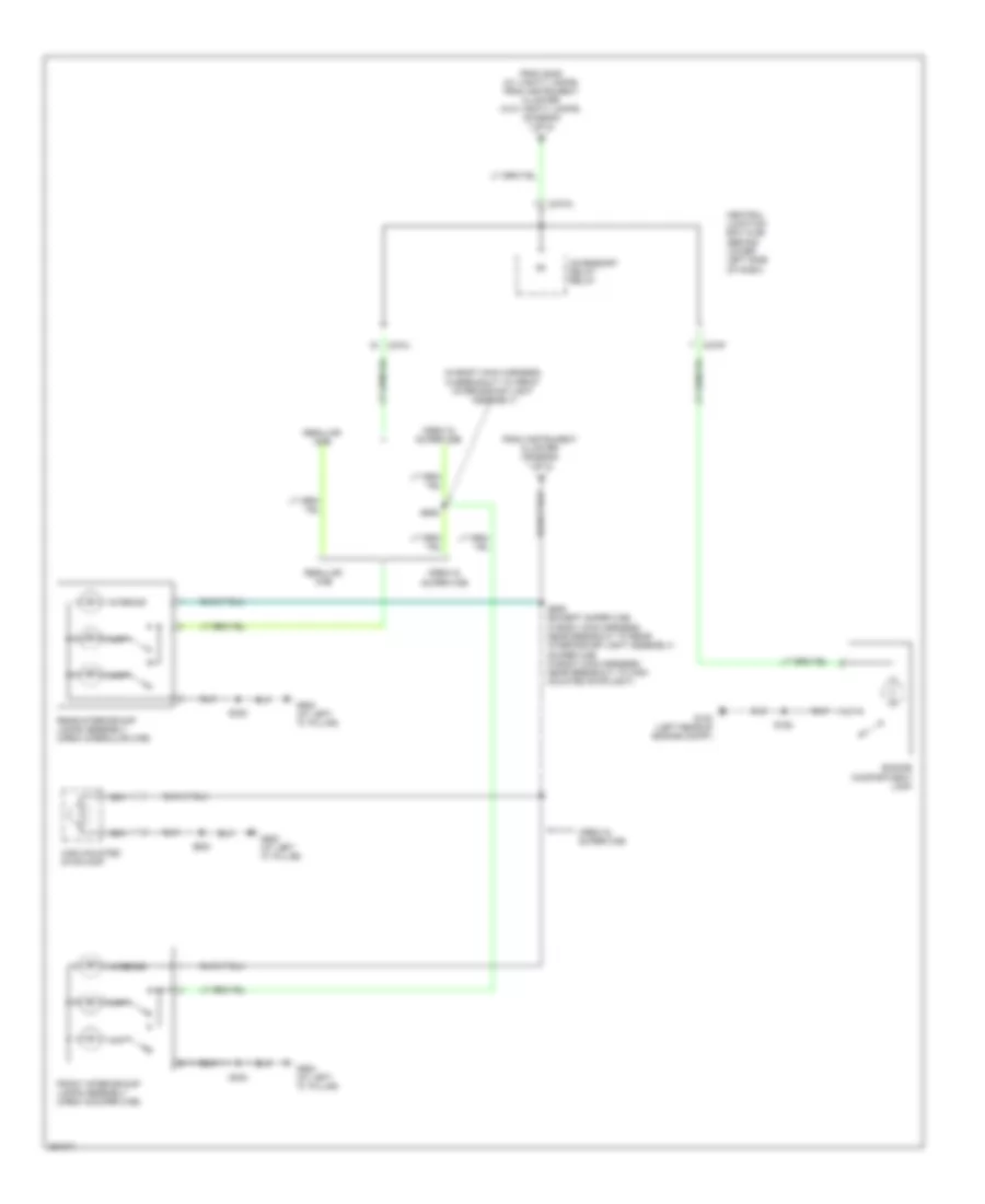
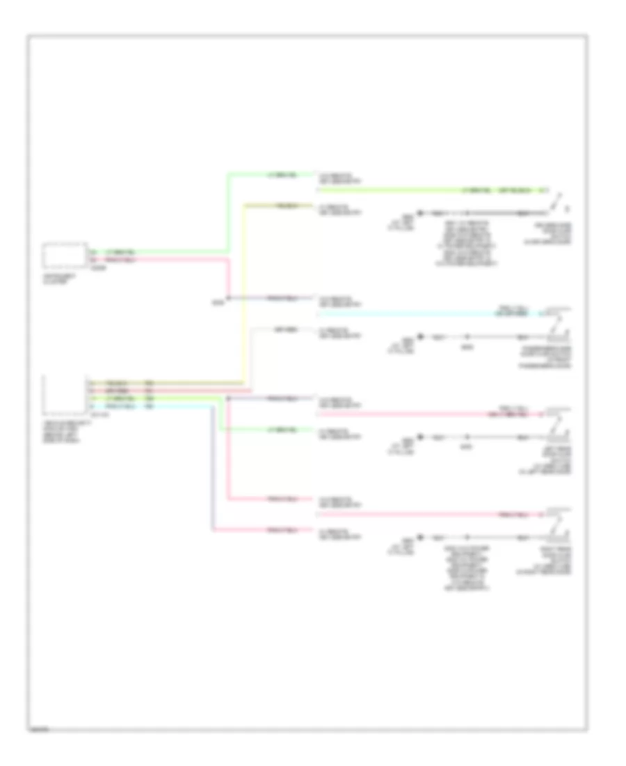
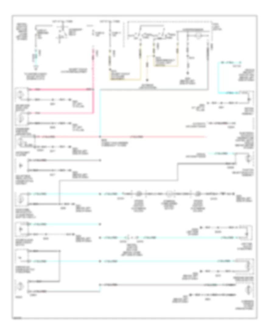
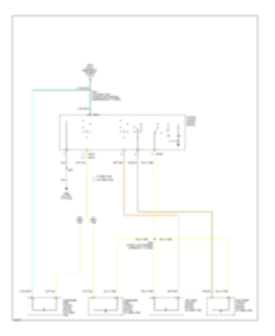
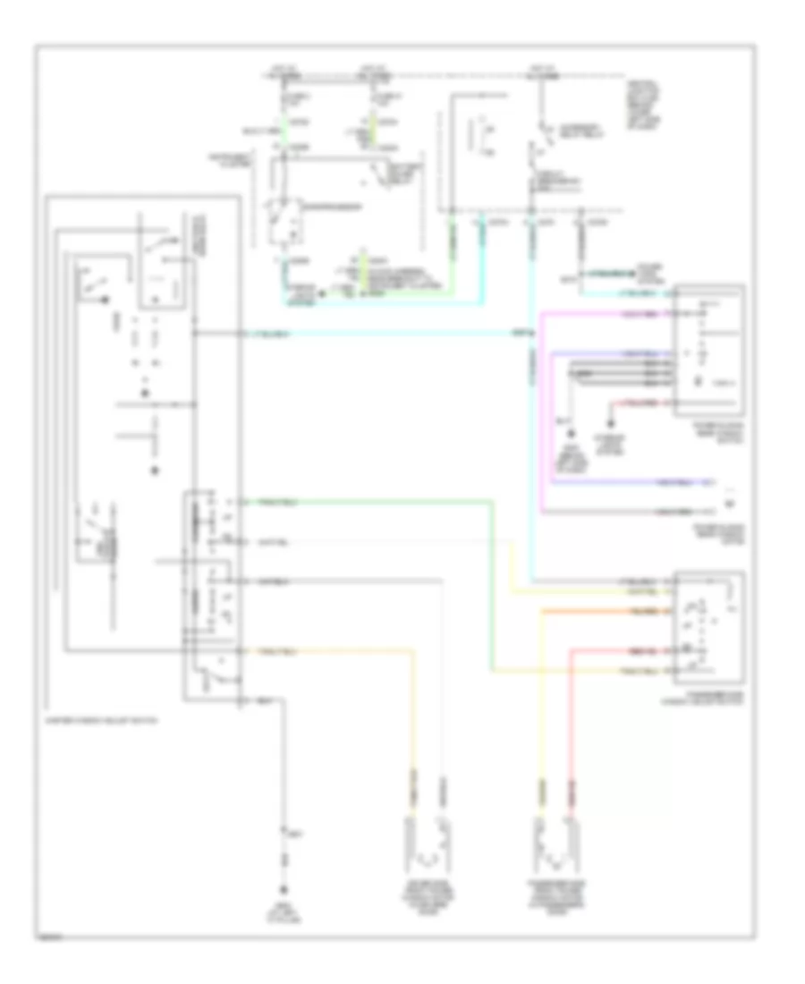
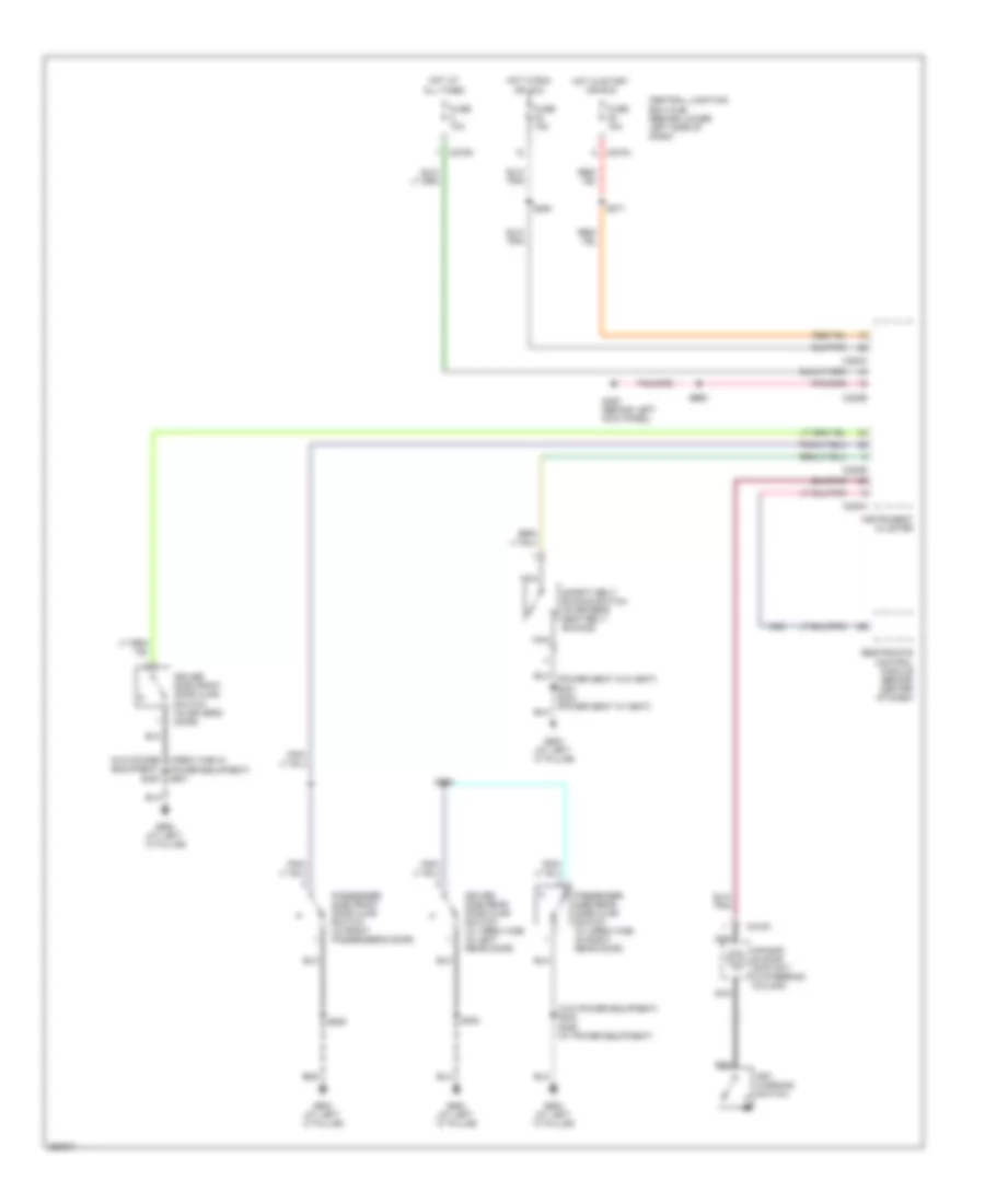
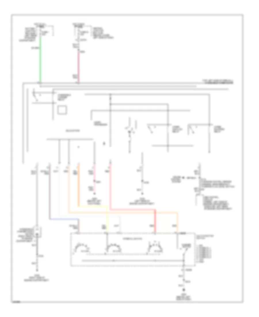
Manual A/C Wiring Diagram for Ford Cab & Chassis F350 Super Duty 2007
List of elements for Manual A/C Wiring Diagram for Ford Cab & Chassis F350 Super Duty 2007:
- (behind left side of dash) g201
- (diesel)
- (except diesel)
- (in engine control harness, in breakout to front heater blower motor resistor) s152
- (in engine control harness, in breakout to powertrain control module)
- (in engine control harness, near breakout to g100) s124
- (in engine control sensor & fuel charge harness) s192
- (in engine control sensor harness, in breakout to c140) (except diesel) s122
- (in main harness, near breakout to radio) s290
- (in main harness, near breakout to temperature blend door actuator) s257
- (left rear of engine compt) g100
- (left side of engine compt) g101
- (right side of engine compt) g108
- A/c clutch field coil (on a/c compressor)
- A/c clutch relay
- A/c compressor clutch diode
- A/c compressor cycling switch (right rear of engine compartment, on a/c accumulator)
- A/c high pressure switch (5.4l: right side of engine compt) (6.8l: lower right front of engine)
- A/c press sw in
- A/c press switch sig rtn
- Battery junction box (bjb) (left rear of engine compt)
- Blower motor relay
- Blower motor switch
- C1381a
- C1381c
- C175a
- C270a
- C270f
- C270h
- C289
- C294a
- C294b
- C294c
- Central junction box (cjb) (behind lower left side of dash)
- Cooling fan speed sig
- Defrost
- Diesel
- Dual pressure switch (right front of engine)
- Electronic fan clutch (diesel) (front of engine)
- Electronic fan clutch ctrl
- Engine controls system
- Engine coolant temperature (ect) sensor (6.0l: front of engine)
- Except diesel
- Floor
- Front function selector switch assembly
- Front heater blower motor resistor (right front of engine compt)
- Fuse 15a
- Fuse 17 10a
- Fuse 2 40a
- Fuse 20a
- Fuse 23 20a
- Fuse 27 15a
- G108 (right side of engine compt)
- Heater blower motor (right rear side of engine compt)
- High
- Hot at all times
- Hot in run
- Hot in start or run
- Illumination
- Interior lights system
- Low
- Max
- Med
- Mix
- Mode switch
- Nca
- Normal
- Off
- Powertrain control module (pcm) (diesel) (left side of engine compt)
- Powertrain control module (pcm) (diesel: left side of engine compt) (except diesel: left side of firewall)
- Red
- S106 (in engine control sensor harness, in breakout to powertrain control module)
- S116
- S119
- S162 (in engine control sensor harness, near breakout to g100)
- S180 (in engine control sensor harness, near breakout to g108)
- S193 (in engine control sensor & fuel charge harness, near breakout to exhaust back pressure sensor)
- S235 (in main harness, near breakout to auxiliary relay box 1)
- Sig rtn
- Tan/red
- Temperature blend door actuator (behind right side of dash)
- Temperature control potentiometer
- To g108)
- Vacuum pump motor (diesel) (right side of engine compt)
- Vent
- Vref
ANTI-LOCK BRAKES
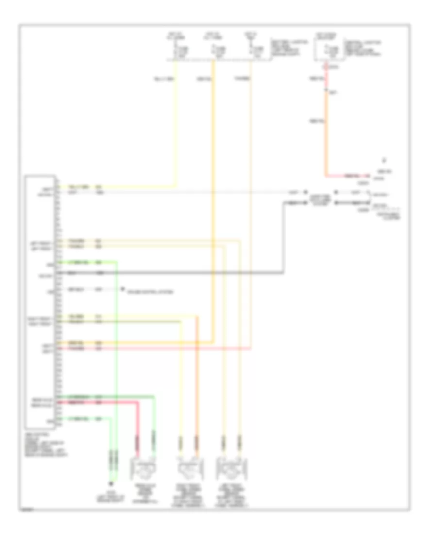
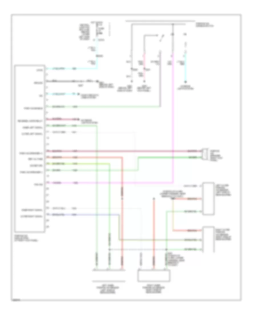
Anti-lock Brakes Wiring Diagram for Ford Cab & Chassis F350 Super Duty 2007
List of elements for Anti-lock Brakes Wiring Diagram for Ford Cab & Chassis F350 Super Duty 2007:
- Abs control module (diesel: left side of engine compt) (except diesel: left rear of engine compt)
- Abs ind
- Battery junction box (bjb) (left rear of engine compt)
- C220a
- C220b
- C270a
- Central junction box (cjb) (behind lower left side of dash)
- Computer data lines system
- Cruise control system
- Fuse f1.11 10a
- Fuse f1.22 60a
- Fuse f1.23 60a
- Fuse f2.45 10a
- G105 (left front of engine compt)
- Gnd
- Hot at all times
- Hot in run
- Hot in run or start
- Hs can +
- Hs can -
- Instrument cluster
- Left front +
- Left front -
- Left front wheel speed sensor (except diesel: at left front wheel assembly)
- Rear axle +
- Rear axle -
- Rear axle speed sensor (on differential)
- Red/pnk
- Right front +
- Right front -
- Right front wheel speed sensor (except diesel: at right front wheel assembly)
- S271
- Tan/red
- Vbatt
- Vpwr
- Vss
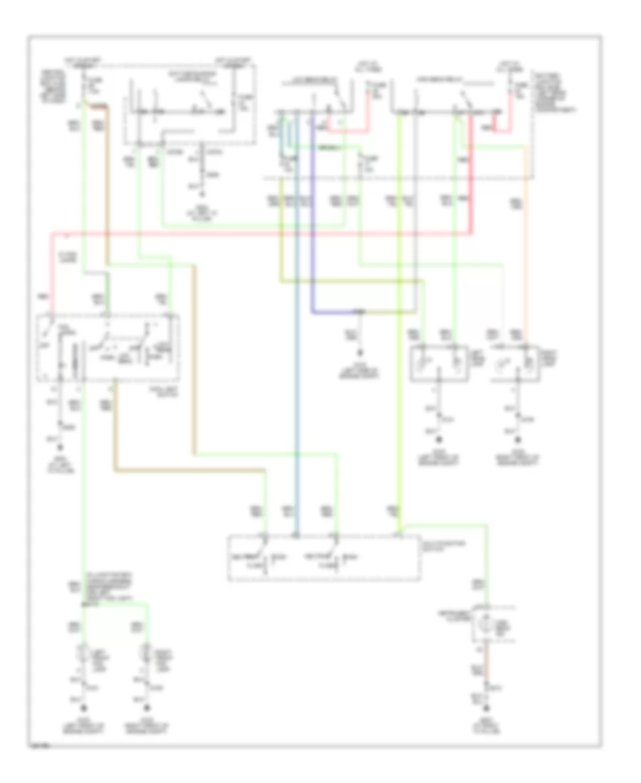
ANTI-THEFT
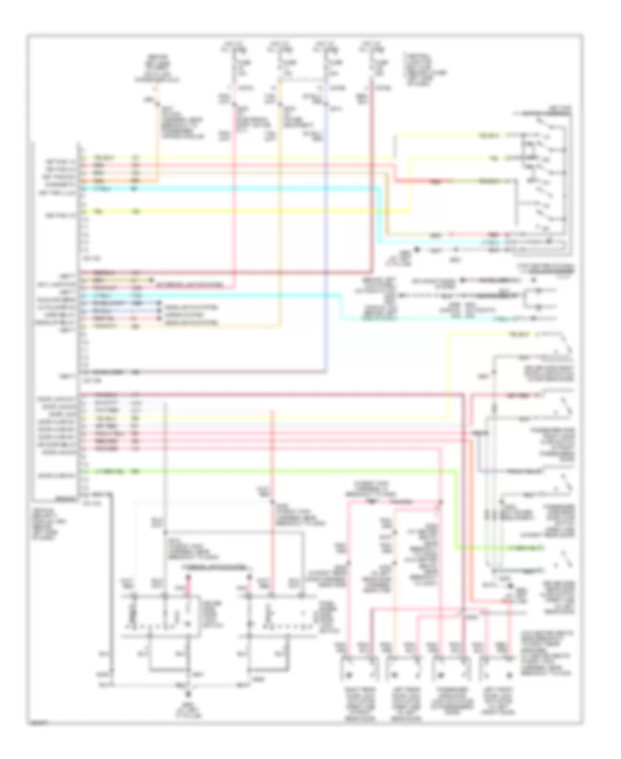
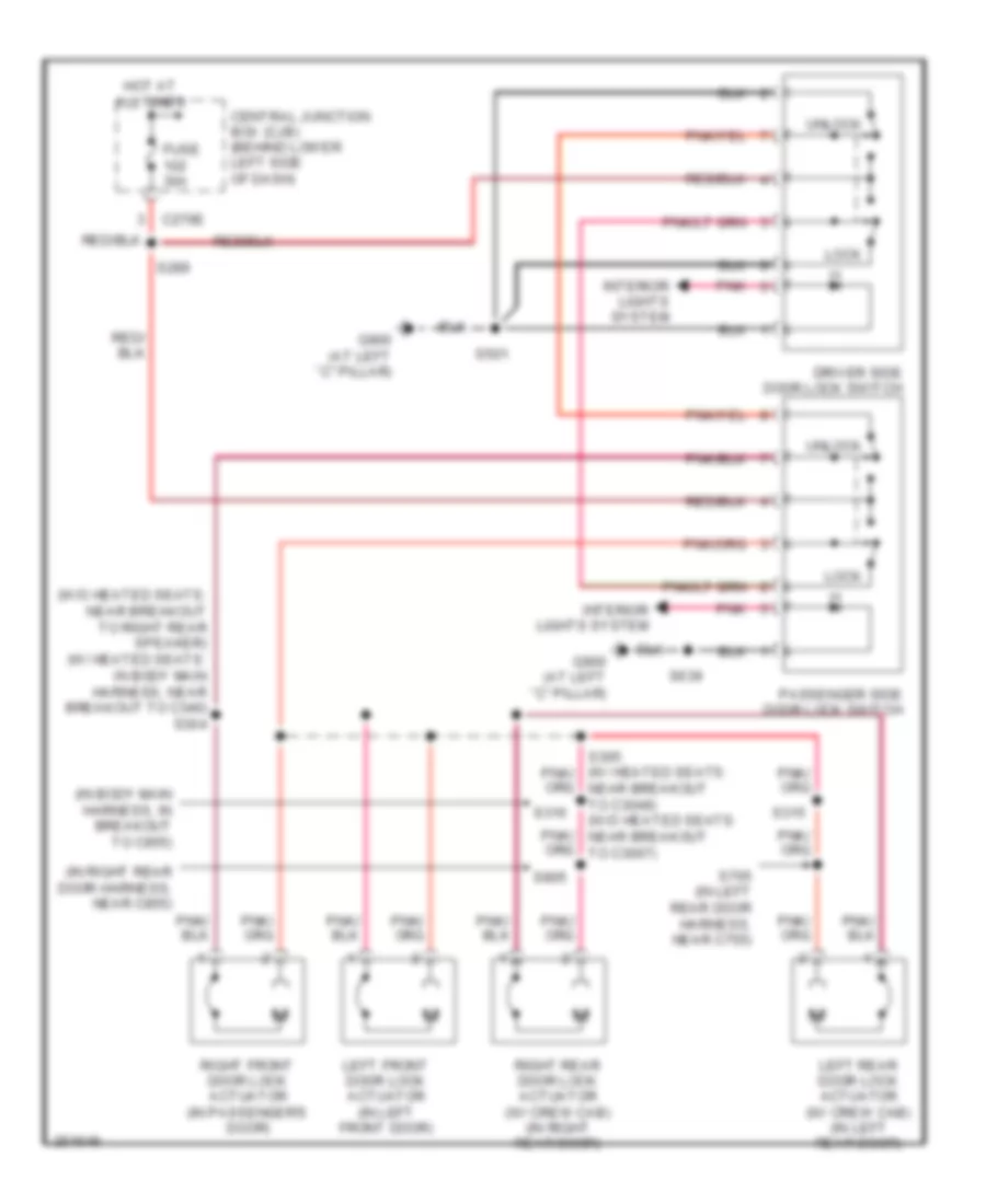
Anti-theft Wiring Diagram for Ford Cab & Chassis F350 Super Duty 2007
List of elements for Anti-theft Wiring Diagram for Ford Cab & Chassis F350 Super Duty 2007:
- (behind
- (behind left kick panel) (automatic a/c) g300 g201 (manual a/c) (behind left side of dash)
- (in body main harness, in breakout to c855) s316
- (manual a/c)
- (top center of dash) sunload sensor
- (w/o heated seats: near breakout to right rear speaker) (w/ heated seats: in body main harness, near breakout to c340)
- 1/2
- 3/4
- 5/6
- 7/8
- 9/0
- Air conditioning system
- Autolamps on
- C2113a
- C2113b
- C2113c
- C270a
- C270b
- C270e
- Central junction box (cjb) (behind lower left side of dash)
- Diagnostic
- Door ajar sw
- Door lock
- Door lock out
- Door unlock
- Dr door relay
- Driver side door lock switch
- Driver side front door ajar switch (in driver's door)
- Driver side rear door ajar switch (crew cab) (in left rear door)
- Equipment)
- Ext lamp pwr
- Exterior lights system
- Fuse 10a
- Fuse 15a
- Fuse 30a
- G900 (at left "c" pillar)
- G900 (at left ``c" pillar)
- Ground
- Headlights system
- Headlmp relay
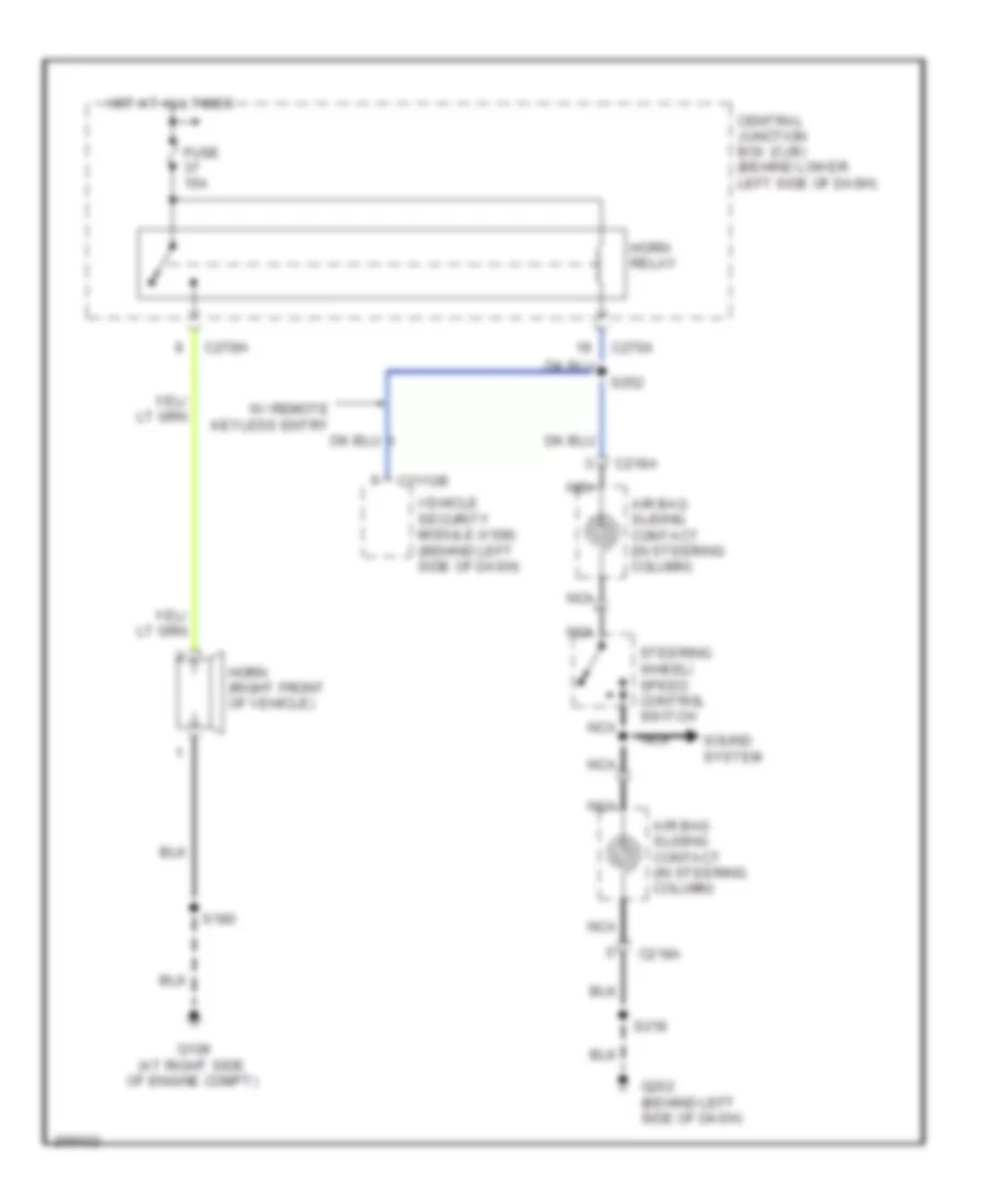
- Horn relay
- Horns system
- Hot at all times
- Interior lights system
- Key pad 1/2
- Key pad 3/4
- Key pad 7/8
- Key pad com
- Key pad illum
- Key pad switch assembly
- Left front door lock actuator (in left front door)
- Left rear door lock actuator (crew cab) (in left rear door)
- Left side of dash) data link connector (dlc)
- Lock
- Pass- enger side door lock switch
- Passenger side door lock actuator (in passenger's door)
- Passenger side front door ajar switch (in front passenger's door)
- Passenger side rear door ajar switch (crew cab) (in right rear door)
- Pnk
- Red
- Right rear door lock actuator (crew cab) (in right rear door)
- S214
- S230 (w/ electronic shift on the fly)
- S247 (in main harness, near breakout to passenger air bag module)
- S272 (w/ power equipment)
- S290 s201 (automatic a/c)
- S300
- S304
- S305 (w/ heated seats: near breakout to c3049) (w/o heated seats: near breakout to c3007)
- S306
- S315
- S318 (in body main harness, near breakout to g300)
- S329 (in body main harness, near breakout to g300)
- S501
- S639
- S705 (in left rear door harness, near c755)
- S805 (in right rear door harness, near c855)
- Sunload sens
- Unlock
- Vbatt
- Vehicle security module (vsm) (behind left side of dash)
COMPUTER DATA LINES
Computer Data Lines Wiring Diagram for Ford Cab & Chassis F350 Super Duty 2007
List of elements for Computer Data Lines Wiring Diagram for Ford Cab & Chassis F350 Super Duty 2007:
- (except diesel)
- (except diesel) s109
- (in engine control sensor harness, in breakout to abs control module)
- (in main harness, in breakout to data link connector)
- (in main harness, near breakout to instrument cluster) s225
- Abs control module (except diesel: left rear of engine compt) (diesel: left side of engine compt)
- C1381a
- C175b
- C2113c
- C2142b
- C220b
- C228b
- C270d
- C281b
- Can h
- Can l
- Central junction box (cjb) (behind lower left side of dash)
- Data link connector (dlc) (behind left side of dash)
- Diesel
- Electronic automatic temperature control (eatc) module (behind center of dash)
- Except diesel
- Feps
- Four wheel drive control module (behind right side of dash)
- Fuse 12 20a
- G101 (except diesel: left rear of engine compt) (diesel: left side of engine compt)
- G202 (behind left side of dash)
- Hot at all times
- Hs can+
- Hs can-
- Instrument cluster
- Iso
- Parking aid module (pam) (right kick panel)
- Powertrain control module (pcm) (except diesel: left side of firewall) (diesel: left side of engine compt)
- Restraints control module (behind center of dash)
- S140 (diesel)
- S142 (diesel)
- S146
- S213
- S217
- S220
- S242
- S247 (in main harness, near breakout to passenger air bag module)
- Trailer brake control module (behind center of dash)
- Ubp
- Vehicle security module (vsm) (behind left side of dash)
- W/ eatc
- W/ electronic shift on the fly
- W/ parking aid
- W/ remote keyless entry
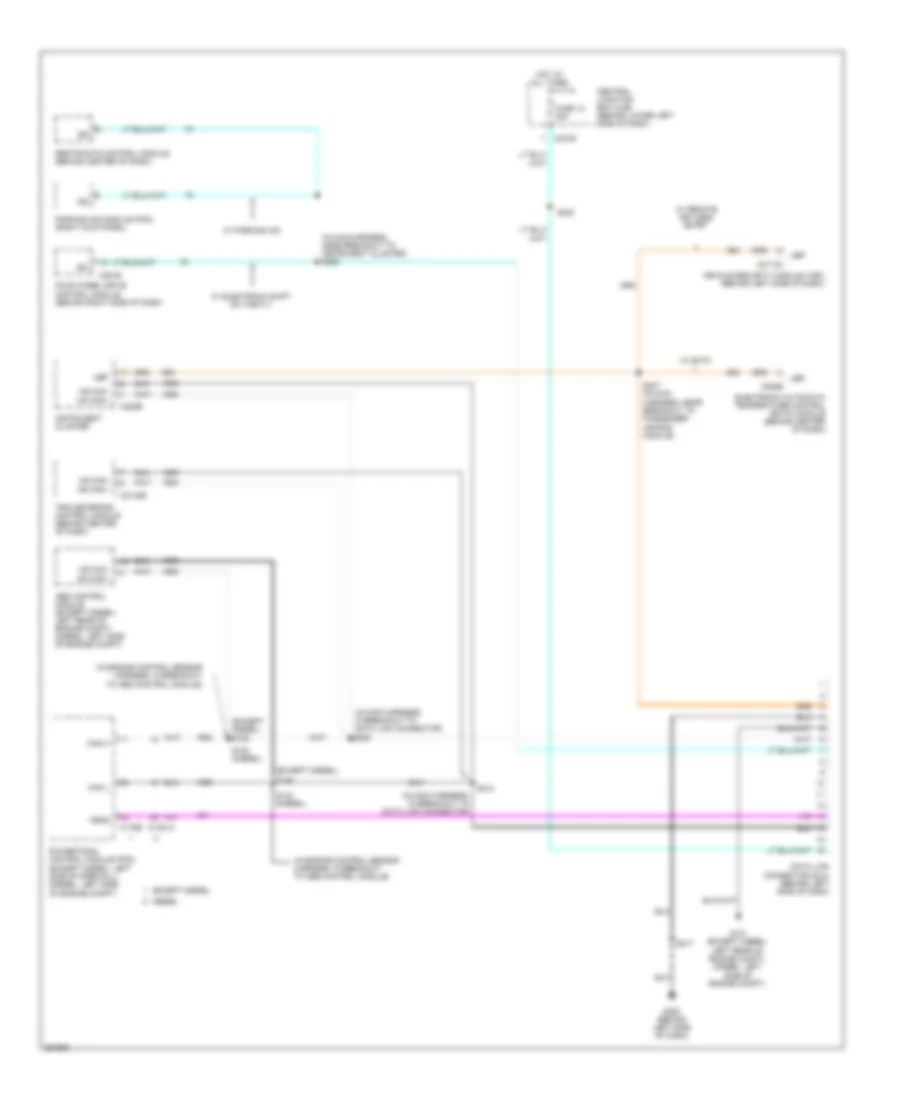
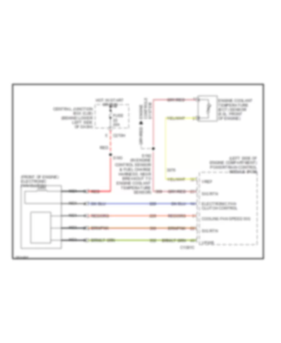
COOLING FAN
6.0L DIESEL
6.0L Diesel, Cooling Fan Wiring Diagram for Ford Cab & Chassis F350 Super Duty 2007
List of elements for 6.0L Diesel, Cooling Fan Wiring Diagram for Ford Cab & Chassis F350 Super Duty 2007:
- (front of engine) electronic fan clutch
- (left side of engine compartment) powertrain control module (pcm)
- C1381c
- C270h
- Central junction box (cjb) (behind lower left side of dash)
- Cooling fan speed sig
- Electronic fan clutch control
- Engine controls system
- Engine coolant temperature (ect) sensor (6.0l: front of engine)
- Fuse 20a
- Hot in start or run
- Nca
- Red
- S192 (in engine control sensor & fuel charge harness, near breakout to engine coolant temperature sensor)
- S193
- Sig rtn
- Vpwr
- Vref
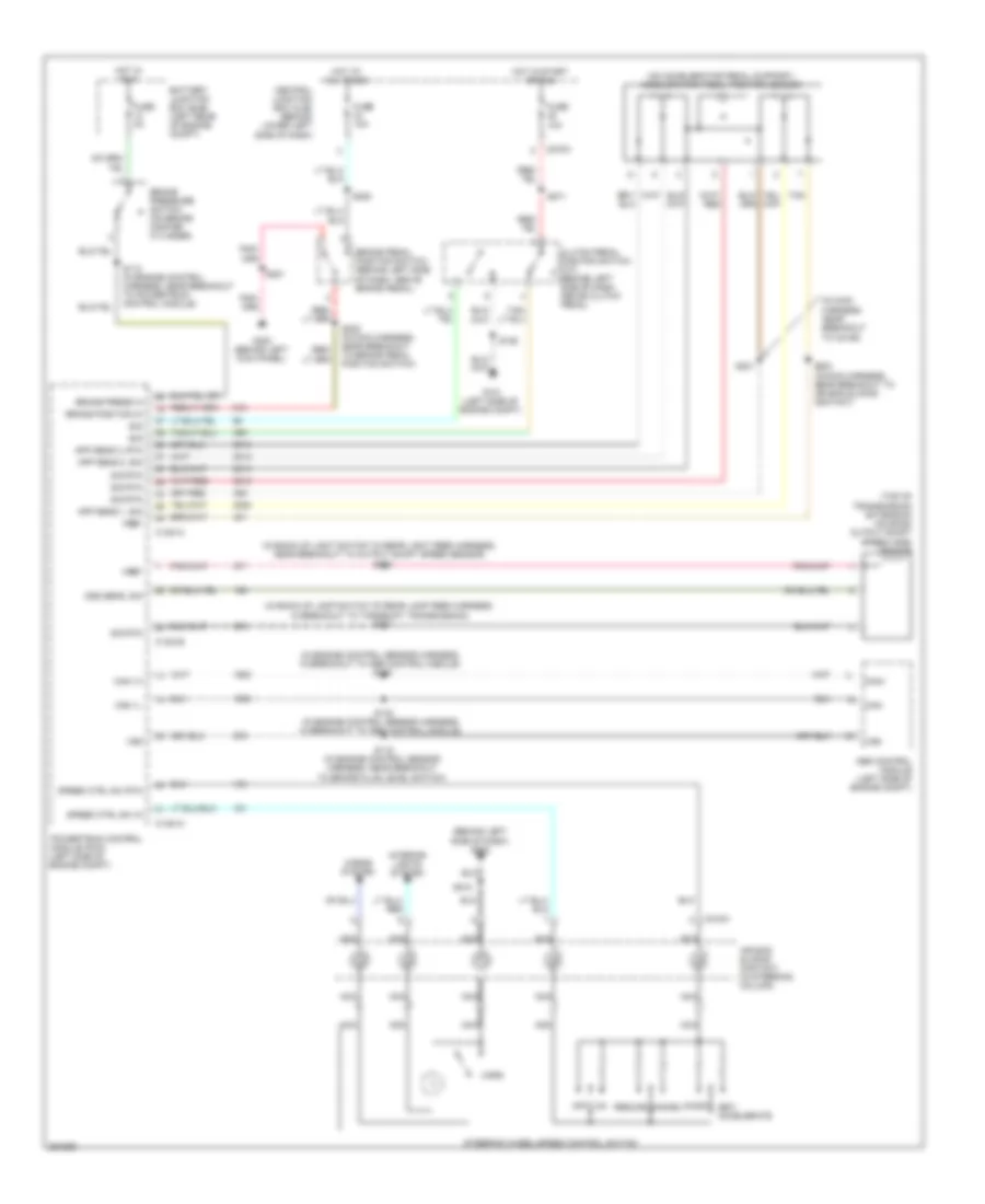
CRUISE CONTROL
5.4L
5.4L, Cruise Control Wiring Diagram for Ford Cab & Chassis F350 Super Duty 2007
List of elements for 5.4L, Cruise Control Wiring Diagram for Ford Cab & Chassis F350 Super Duty 2007:
- (behind left side of dash) g202
- (in engine control sensor harness, in breakout to abs control module) s109
- (in main harness, near breakout to c2186) s221
- (not used)
- (on accelerator pedal support) accelerator pedal position sensor
- (on throttle body) throttle position sensor (tps)
- Abs control module (left rear of engine compt)
- Air bag sliding contact (in steering column)
- App sens 1, sig
- App sens 2, sig
- App sens 3, pwr
- App sens 3, rtn
- App sens 3, sig
- Battery junction box (bjb) (left rear of engine compartment)
- Brake pedal position switch (behind left side of dash, above brake pedal)
- Brake position in
- Brake press in
- Brake pressure switch (bottom of master cylinder)
- C175a
- C175b
- C218a
- C270a
- Can+
- Can-
- Cancel
- Central junction box (cjb) (behind lower left side of dash)
- Clutch pedal position switch (behind left side of dash, above clutch pedal)
- Coast
- Fuse 10a
- Fuse 2a
- G300 (behind left kick panel)
- Horn
- Horns system
- Hot at all times
- Hot in run
- Interior lights system
- M/t
- Nca
- Off
- Powertrain control module (pcm) (left side of firewall)
- Resume
- S115 (in engine control sensor harness, near breakout to brake fluid level switch)
- S146 (in engine control sensor harness, in breakout to abs control module)
- S201
- S205 (in main harness, near breakout to brake pedal position switch)
- S208
- S218
- S223 (in main harness, near breakout to air bag sliding contact)
- Scp+
- Scp-
- Set/ accelerate
- Sig rtn
- Speed ctrl sw in
- Speed ctrl sw rtn
- Steering wheel/speed control switch
- Tan
- Tps sig 1
- Tps sig 2
- Volt ref
- Vss
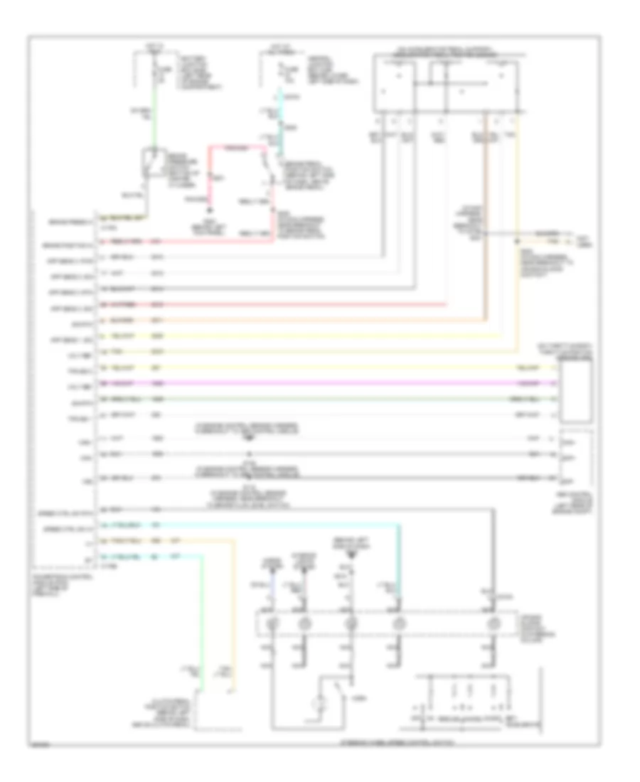
6.0L DIESEL
6.0L Diesel, Cruise Control Wiring Diagram for Ford Cab & Chassis F350 Super Duty 2007
List of elements for 6.0L Diesel, Cruise Control Wiring Diagram for Ford Cab & Chassis F350 Super Duty 2007:
- (behind left side of dash) g202
- (in back-up lamp switch to rear lamp feed harness, in breakout to torqshift transmission) s127
- (in back-up light switch to rear light feed harness, near breakout to output shaft speed sensor) s128
- (in engine control sensor harness, in breakout to abs control module) s140
- (in main harness, near breakout to c2186)
- (on accelerator pedal support) accelerator pedal position sensor
- (top of transmission extension housing) output shaft speed (oss) sensor
- Abs control module (left side of engine compt)
- Air bag sliding contact (in steering column)
- App sens 1, sig
- App sens 2, rtn
- App sens 2, sig
- Battery junction box (bjb) (left rear of engine compt)
- Brake pedal position switch (behind left side of dash, above brake pedal)
- Brake position in
- Brake press in
- Brake pressure switch (on brake master cylinder)
- C1381a
- C1381b
- C218a
- C270a
- Can 1h
- Can 1l
- Can+
- Can-
- Cancel
- Central junction box (cjb) (behind lower left side of dash)
- Clutch pedal position switch (m/t) (behind left side of dash, above clutch pedal)
- Coast
- Fuse 10a
- Fuse 2a
- G101 (left side of engine compt)
- G300 (behind left kick panel)
- Horn
- Horns system
- Hot at all times
- Hot in run
- Hot in start or run
- Interior lights system
- Nca
- Off
- Oss sens, sig
- Powertrain control module (pcm) (left side of engine compt)
- Resume
- S106
- S112 (in engine control harness, near breakout to powertrain control module)
- S115 (in engine control sensor harness, near breakout to brake fluid level switch)
- S142 (in engine control sensor harness, in breakout to abs control module)
- S201
- S205 (in main harness, near breakout to brake pedal position switch)
- S208
- S218
- S221
- S223 (in main harness, near breakout to air bag sliding contact)
- S271
- Set/ accelerate
- Sig
- Sig rtn
- Speed ctrl sw in
- Speed ctrl sw rtn
- Steering wheel/speed control switch
- Tan
- Vref
- Vss
6.8L
6.8L, Cruise Control Wiring Diagram for Ford Cab & Chassis F350 Super Duty 2007
List of elements for 6.8L, Cruise Control Wiring Diagram for Ford Cab & Chassis F350 Super Duty 2007:
- (behind left side of dash) g202
- (in engine control sensor harness, in breakout to abs control module) s109
- (in main harness, near breakout to c2186) s221
- (not used)
- (on accelerator pedal support) accelerator pedal position sensor
- (on throttle body) throttle position sensor (tps)
- Abs control module (left rear of engine compt)
- Air bag sliding contact (in steering column)
- App sens 1, sig
- App sens 2, sig
- App sens 3, pwr
- App sens 3, rtn
- App sens 3, sig
- Battery junction box (bjb) (left rear of engine compartment)
- Brake pedal position switch (behind left side of dash, above brake pedal)
- Brake position in
- Brake press in
- Brake pressure switch (bottom of master cylinder)
- C175a
- C175b
- C218a
- C270a
- Can+
- Can-
- Cancel
- Central junction box (cjb) (behind lower left side of dash)
- Clutch pedal position switch (behind left side of dash, above clutch pedal)
- Coast
- Fuse 10a
- Fuse 2a
- G300 (behind left kick panel)
- Horn
- Horns system
- Hot at all times
- Hot in run
- Interior lights system
- M/t
- Nca
- Off
- Powertrain control module (pcm) (left side of firewall)
- Resume
- S115 (in engine control sensor harness, near breakout to brake fluid level switch)
- S146 (in engine control sensor harness, in breakout to abs control module)
- S201
- S205 (in main harness, near breakout to brake pedal position switch)
- S208
- S218
- S223 (in main harness, near breakout to air bag sliding contact)
- Scp+
- Scp-
- Set/ accelerate
- Sig rtn
- Speed ctrl sw in
- Speed ctrl sw rtn
- Steering wheel/speed control switch
- Tan
- Tps sig 1
- Tps sig 2
- Volt ref
- Vss
DEFOGGERS
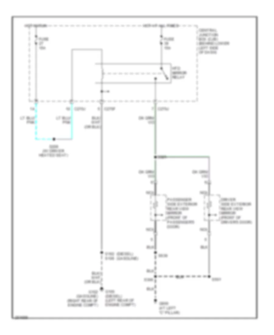
Defoggers Wiring Diagram for Ford Cab & Chassis F350 Super Duty 2007
List of elements for Defoggers Wiring Diagram for Ford Cab & Chassis F350 Super Duty 2007:
- (diesel)
- (gasoline)
- C270f
- C270j
- Central junction box (cjb) (behind lower left side of dash)
- Driver side exterior rear view mirror (front of driver's door)
- Fuse 15a
- G100 (diesel) (left rear of engine compt)
- G102 (gasoline) (right rear of engine compt)
- G900 (at left "c" pillar)
- Hot at all times
- Hot in run
- Htd mirror relay
- Nca
- Passenger side exterior rear view mirror (front of passenger's door)
- S106
- S162
- S209 (w/ driver heated seat)
- S306
- S321
- S501
- S639
ENGINE PERFORMANCE
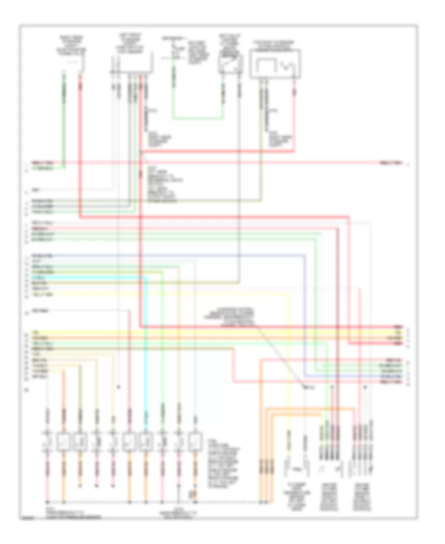
5.4L
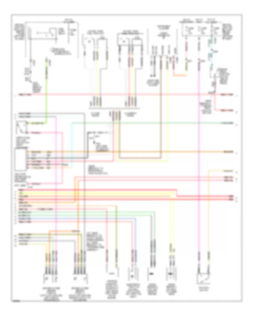
5.4L, Engine Performance Wiring Diagram (1 of 5) for Ford Cab & Chassis F350 Super Duty 2007
List of elements for 5.4L, Engine Performance Wiring Diagram (1 of 5) for Ford Cab & Chassis F350 Super Duty 2007:
- (in engine control sensor & fuel charge harness, near breakout to powertrain control module)
- A/c clutch rly ctrl
- A/c press sw sig
- Air conditioning system
- Brake pressure sw
- C175a
- Camshaft position (ckp) sensor (left bank) (lower front center of engine)
- Camshaft position (ckp) sensor (right bank) (lower right front of engine)
- Ckp sensor +
- Ckp sensor -
- Cmcv cntrl
- Cmcv monitor
- Cmp sensor 1 sig
- Cmp sensor 2 sig
- Coil on plug
- Coil on plug 1 ctrl
- Coil on plug 2 ctrl
- Coil on plug 3 ctrl
- Coil on plug 4 ctrl
- Coil on plug 5 ctrl
- Coil on plug 6 ctrl
- Coil on plug 7 ctrl
- Coil on plug 8 ctrl
- Crankshaft position (cmp) sensor (front of left cylinder head)
- Cyl head temp sens
- Engine oil temperature sensor (eot) (lower right rear of engine block)
- Eot sensor sig
- Etc motor
- Evap cnsr purge vlv
- Frts ref vol
- Fuel inj 1 ctrl
- Fuel inj 2 ctrl
- Fuel inj 3 ctrl
- Fuel inj 4 ctrl
- Fuel inj 5 ctrl
- Fuel inj 6 ctrl
- Fuel inj 7 ctrl
- Fuel inj 8 ctrl
- Fuel rail press sens
- Fuel rail temp sens
- Ho2s 11 htr
- Ho2s 11 input
- Ho2s 21 htr
- Ho2s 21 input
- Hpcv element ctrl
- Iat sensor sig
- Ignition transformer capacitor 1 (right front of engine)
- Ignition transformer capacitor 2 (top left front of engine)
- Injection pressure sensor (ips) (top left center of intake manifold)
- Knock sensor 1 +
- Knock sensor 1 -
- Knock sensor 2 +
- Knock sensor 2 -
- Maf sensor sig
- Maf sensor sig rtn
- Nca
- Powertrain control module (left side of firewall)
- S130 (in engine control sensor & fuel charge harness, near breakout to injector pressure sensor)
- S135 (in engine control sensor & fuel charge harness, near breakout to fuel injector 3)
- S145
- Shield drain wire
- Signal return
- Tan
- Tan/red
- Throttle position sensor (tps) (on throttle body)
- Tps 1 sig
- Tps 2 sig
- Tps ref vol
- Tps sig return
- Vct sol 1 ctrl
- Vct sol 2 ctrl
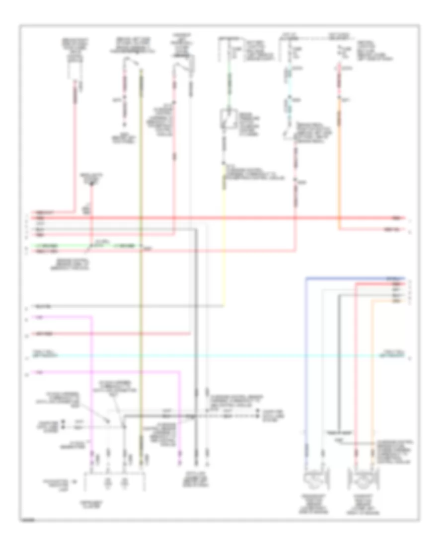
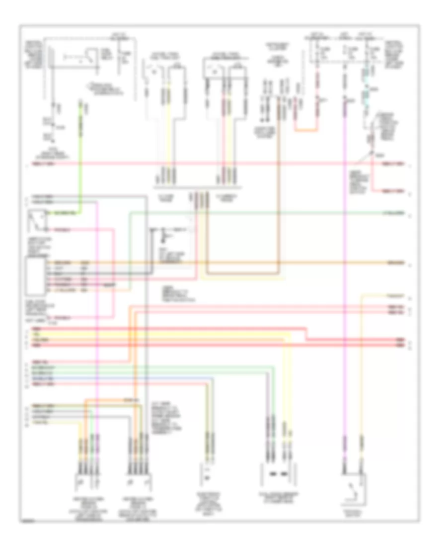
5.4L, Engine Performance Wiring Diagram (2 of 5) for Ford Cab & Chassis F350 Super Duty 2007
List of elements for 5.4L, Engine Performance Wiring Diagram (2 of 5) for Ford Cab & Chassis F350 Super Duty 2007:
- (bottom of master cylinder) brake pressure switch
- (in engine control sensor & fuel charge harness, near breakout to coil on plug 8)
- (in engine control sensor & fuel charge harness, near breakout to powertrain control module)
- (left front of engine compt) mass air flow (maf) sensor
- (on right side valve cover) heated positive crankcase ventilation (pcv) element
- (right rear of engine compt) evap canister purge valve
- (top rear of intake manifold) charge motion control valve (cmcv)
- Battery junction box (bjb) (left rear of engine compt)
- Cylinder head temperature sensor (rear of block, under intake)
- Fuel injectors (1, 2: top right side of engine) (3, 4: top right rear of engine) (5, 6, 7: top left side of engine) (8: top left rear of engine)
- Fuse 2a
- G102 (right rear of engine compt)
- Heated oxygen sensor (ho2s) 11 (on right exhaust manifold)
- Heated oxygen sensor (ho2s) 21 (on left exhaust manifold)
- Hot in run
- Nca
- Red
- S131 (near breakout to injector pressure sensor)
- S132
- S134
- S136 (near breakout to coil on plug 3)
- S137 (in engine control red
- Sensor and fuel charge harness, near breakout to fuel injector 8)
- Tan
- Tan/red
- Variable camshaft timing (vct) solenoid 1 (right bank) (left top front of engine)
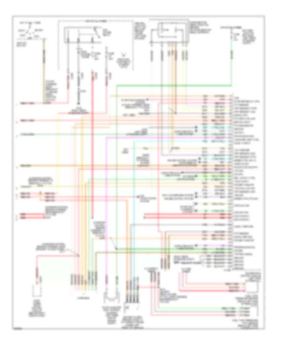
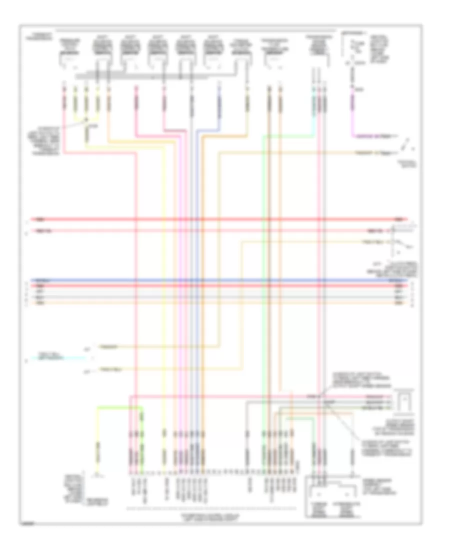
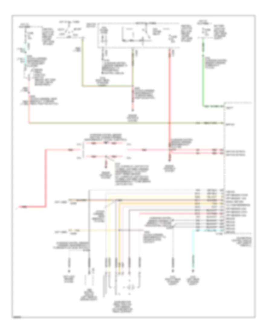
5.4L, Engine Performance Wiring Diagram (3 of 5) for Ford Cab & Chassis F350 Super Duty 2007
List of elements for 5.4L, Engine Performance Wiring Diagram (3 of 5) for Ford Cab & Chassis F350 Super Duty 2007:
- (in back-up light switch to rear light feed harness, near breakout to torqshift transmission)
- (m/t: near breakout to reversing lights switch) (a/t: near breakout to output shaft speed sensor) s127
- C175c
- Ho2s 12 htr
- Ho2s 12 sig
- Ho2s 22 htr
- Ho2s 22 sig
- Intermediate shaft speed sensor
- Iss sensor sig
- Oss sensor
- Output shaft speed (oss) sensor (top of transmission extension housing)
- Powertrain control module (left side of firewall)
- Press ctrl sol
- Pressure control (pc-a) solenoid
- Red
- S128 (in back-up light switch to rear light feed harness, near breakout to output shaft speed sensor)
- S129
- Shift sol a
- Shift sol b
- Shift sol c
- Shift sol d
- Shift sol e
- Shift sol vpwr
- Shift solenoid pressure control a (sspc-a)
- Shift solenoid pressure control b (sspc-b)
- Shift solenoid pressure control c (sspc-c)
- Shift solenoid pressure control d (sspc-d)
- Shift solenoid pressure control e (sspc-e)
- Signal return
- Speed sensor assembly (top left side of transmission)
- Tcc sol ctrl
- Tft sensor sig
- Torqshift transmission
- Torque converter clutch solenoid
- Transmission fluid temperature (tft) sensor
- Transmission range sensor assembly (tr-p)
- Trsa gnd
- Trsa ref vol
- Trsa sig
- Tss sensor sig
- Turbine shaft speed sensor
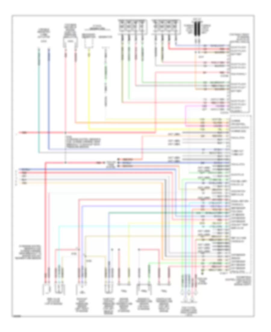
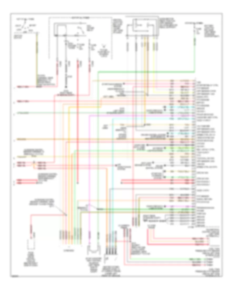
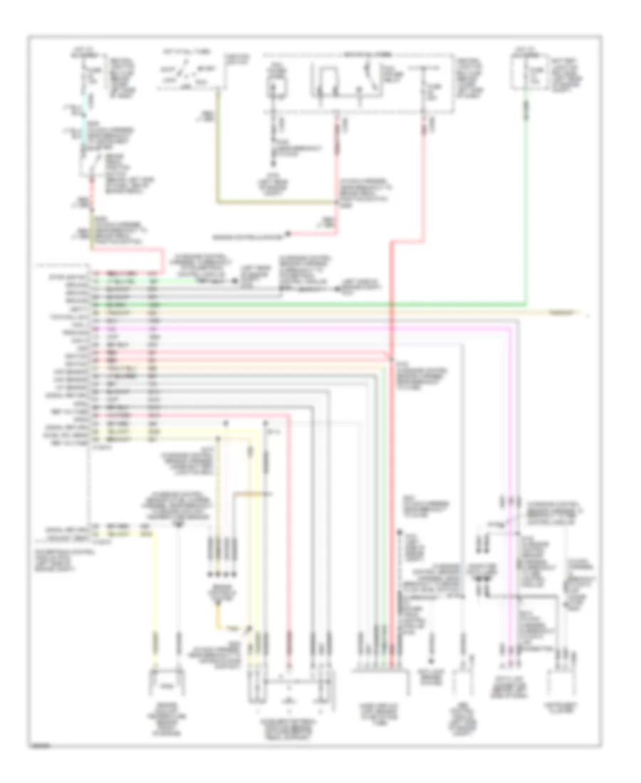
5.4L, Engine Performance Wiring Diagram (4 of 5) for Ford Cab & Chassis F350 Super Duty 2007
List of elements for 5.4L, Engine Performance Wiring Diagram (4 of 5) for Ford Cab & Chassis F350 Super Duty 2007:
- (a/t: near breakout to output shaft speed sensor) (m/t: near breakout to transfer case assembly)
- (in fuel tank) fuel tank unit
- (near breakout to brake pedal position switch)
- (not used) c145
- Brake pedal position switch (above brake pedal)
- C270a
- C270f
- Central junction box (cjb) (behind lower left side of dash)
- Check engine ind
- Computer data lines system
- Electronic throttle control (etc) motor (on throttle body)
- From pcm power relay (diagram 5 of 5)
- Fuel pump driver module (left rear frame rail)
- Fuel pump relay
- Fuse 10a
- Fuse 15a
- Fuse 20a
- G102 (right rear of engine compt)
- G401 (left side of vehicle underbody)
- Heated oxygen sensor (ho2s) 12 (catalyst monitor) (rear of catalytic converter)
- Heated oxygen sensor (ho2s) 22 (catalyst monitor) (left side of transmission)
- Hot at all times
- Hot in on or start
- Hot in run
- Hs can +
- Hs can -
- Inertia fuel shut-off (ifs) switch (right kick panel)
- Instrument cluster
- Knock sensor 1 (on right cylinder head)
- Knock sensor 2 (top left rear of engine)
- Nca
- Red
- Red/
- Return
- S106
- S138
- S205
- S208
- S234
- S411
- Tow/haul switch
- Variable camshaft timing (vct) solenoid 2 (left bank) (left front top of engine)
- W/ narrow frame
- W/ wide frame
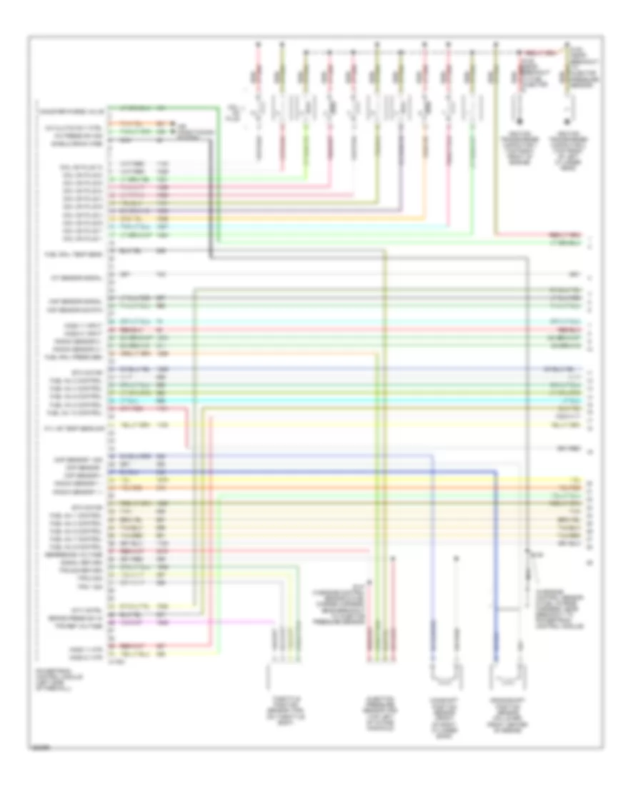
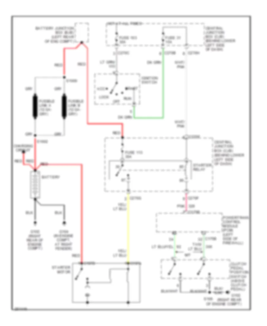
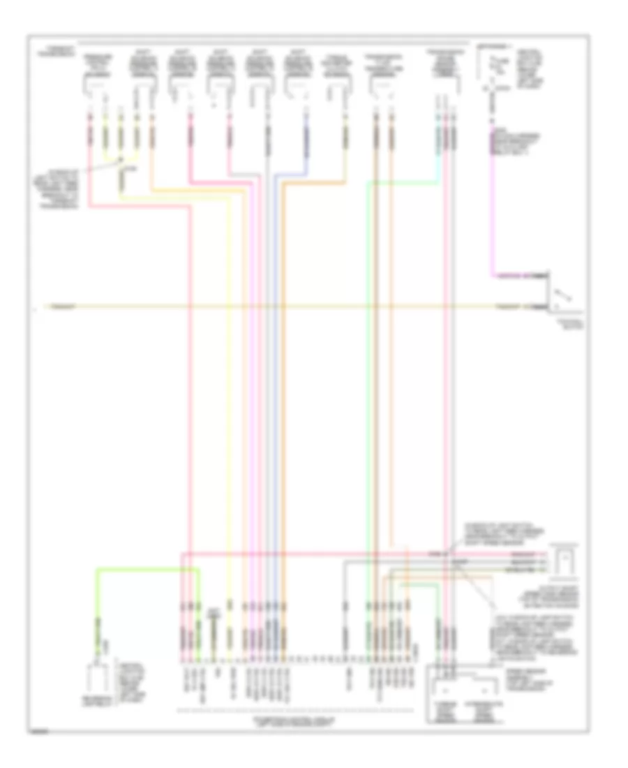
5.4L, Engine Performance Wiring Diagram (5 of 5) for Ford Cab & Chassis F350 Super Duty 2007
List of elements for 5.4L, Engine Performance Wiring Diagram (5 of 5) for Ford Cab & Chassis F350 Super Duty 2007:
- (in engine control sensor harness, in breakout to c140) s122
- (in engine control sensor harness, in breakout to c140) s164
- (in engine control sensor harness, near breakout to c1756) s123
- (in engine control sensor harness, near grommet in dash panel) s111
- (in main harness, near breakout to brake pedal position switch)
- (in main harness, near breakout to c2186) s221
- (near breakout to air bag sliding contact)
- (not used)
- (right rear of engine compt) g102
- (wire end)
- 20a
- Acc
- Accelerator pedal position sensor (on accelerator pedal support)
- Air conditioning system
- Anti-lock brakes system
- App sensor 1 sig
- App sensor 2 sig
- App sensor 3 pwr
- App sensor 3 rtn
- App sensor 3 sig
- Atn sig
- Battery junction box (bjb) (left rear of engine compt)
- Bpp sw input
- C175b
- C270c
- C270f
- C270h
- C281b
- Canister vent ctrl
- Central junction box (cjb) (behind lower left side of dash)
- Computer data lines system
- Cpda sw sig
- Cpsi sw sig
- Cruise control system
- Evap canister vent control solenoid (left rear side of engine compt)
- Exterior lights system
- Four- wheel drive control module (behind right side of dash)
- Fpump drvr mod
- Fpump dvr mod rtn
- From fuel pump relay (diagram 4 of 5)
- Ftp sensor
- Fuel tank pressure (ftp) sensor (above left side of rear axle)
- Fuel tank pressure sensor (above left side of rear axle)
- Fuse
- Fuse 10a
- Fuse 20a
- G100 (left rear of engine compt)
- G102 (right rear of engine compt)
- Ground
- Heated oxygen sensor (ho2s) 13 (w/ narrow frame) (under left front of vehicle)
- Ho2s 13 input
- Ho2s 13 return
- Hot at all times
- Hs can +
- Hs can -
- Ignition switch
- Lock
- Nca
- Off
- Pcm power diode
- Pcm power relay
- Pcm pwr rly
- Pnk
- Power
- Power take off
- Powertrain control module (left side of firewall)
- Programming sig
- Pto engage sig
- Pto rpm ctrl sig
- Red
- Red/pnk
- Rev lmp rly ctrl
- Run
- S106
- S223
- S258
- S412 (except regular cab) (in taillamps harness, near breakout to c140)
- Signal return
- Signal rtn
- Speed ctrl rtn sw
- Speed ctrl sw in
- Start
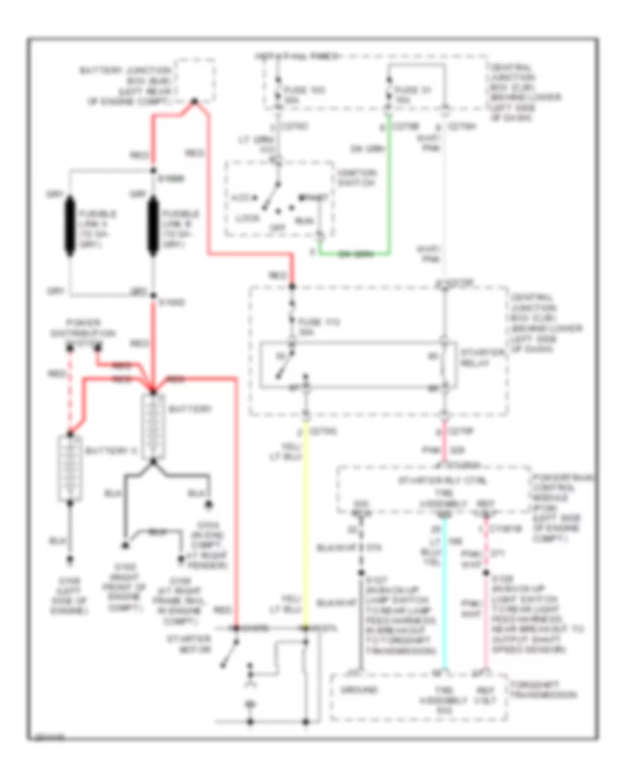
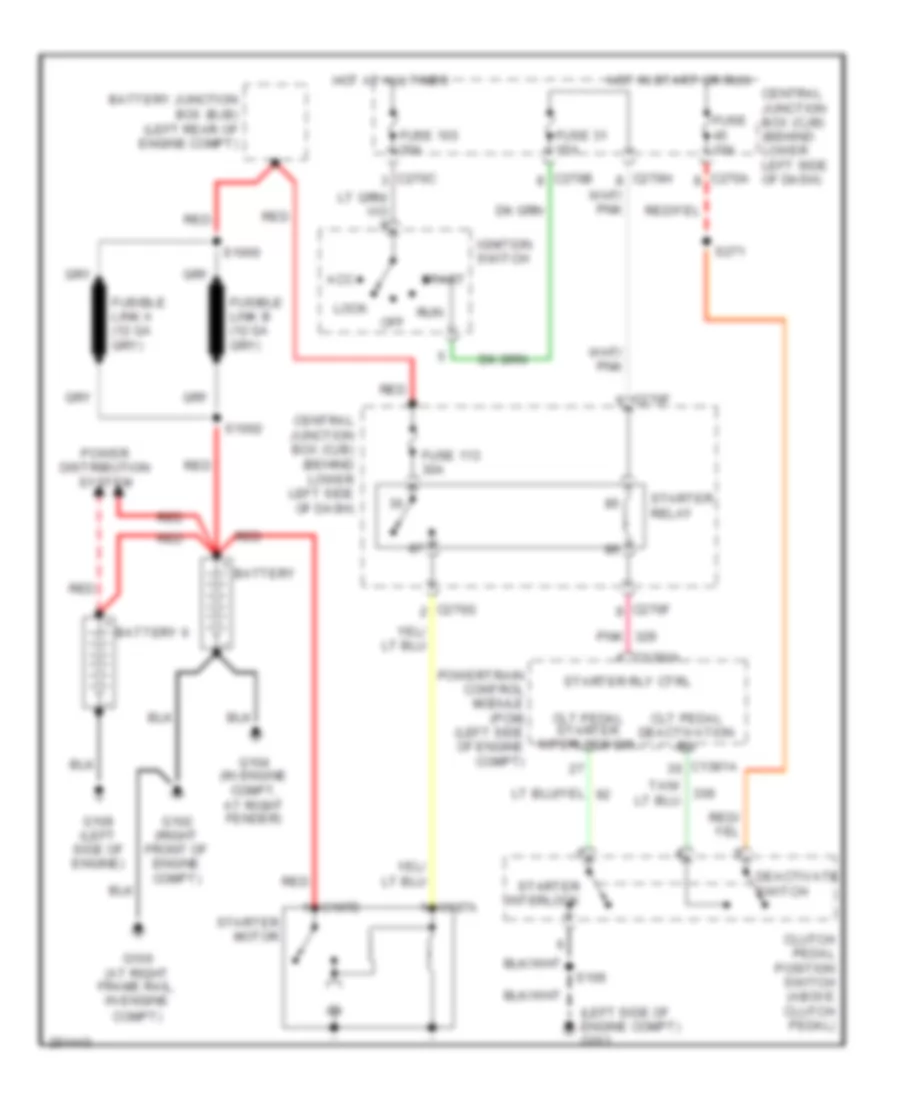
- Starter relay ctrl
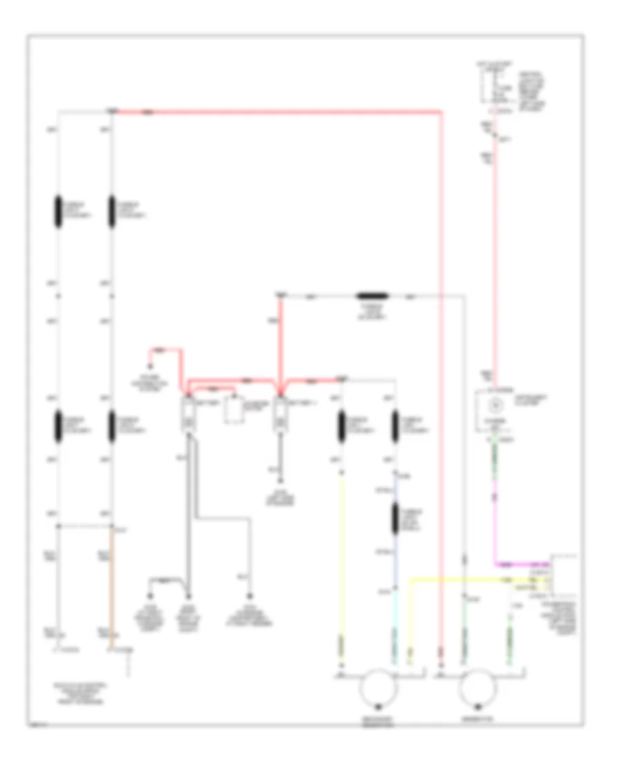
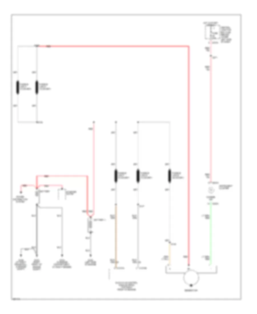
- Starting/ charging system
- Starting/charging system
- Tach ouput
- Tan
- Tow/haul sw sig
- Tr park signal
- Vems aa sig
- Voltage ref
- Vss
- Vss sig
- W/ narrow frame red/pnk
- W/ wide frame
6.0L DIESEL
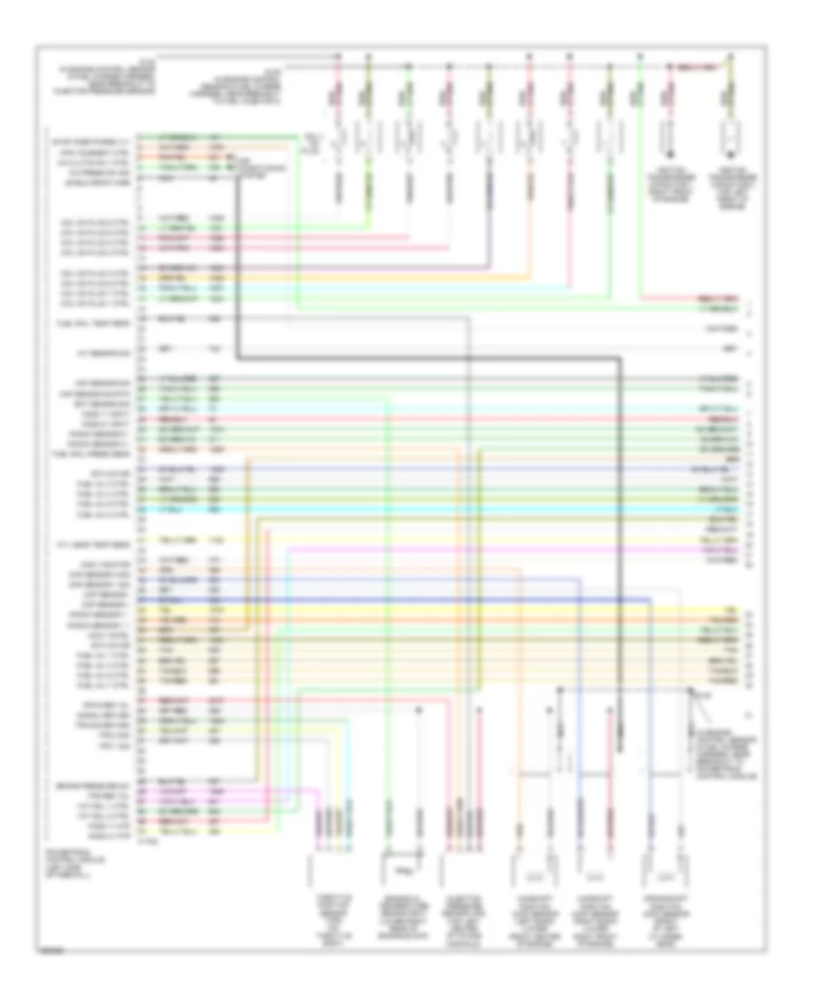
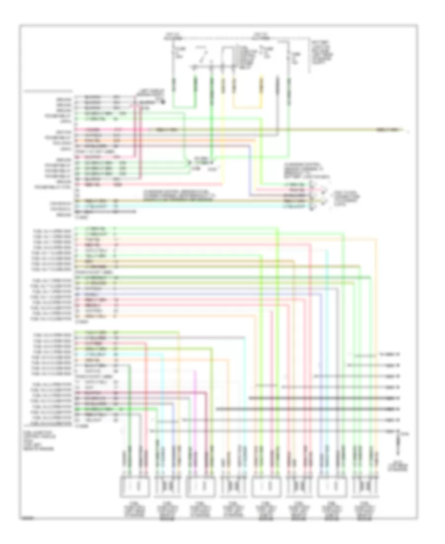
6.0L Diesel, Engine Performance Wiring Diagram (1 of 5) for Ford Cab & Chassis F350 Super Duty 2007
List of elements for 6.0L Diesel, Engine Performance Wiring Diagram (1 of 5) for Ford Cab & Chassis F350 Super Duty 2007:
- (in engine control sensor & fuel charge harness, near breakout to manifold air temperature sensor)
- (in engine control sensor harness, in breakout to battery junction box)
- (left side of engine compt) g101
- (pins 11-21 not used)
- (pins 9-16 not used)
- Battery junction box (bjb) (left rear of engine compt)
- C1388a
- C1388b
- C1388c
- Can bus 2h
- Can bus 2l
- Ckp-o
- Cmp-o
- Ficm to pcm connections (to diagram 5 of 5)
- Fuel inj 1 close gnd
- Fuel inj 1 close pwr
- Fuel inj 1 open gnd
- Fuel inj 1 open pwr
- Fuel inj 2 close gnd
- Fuel inj 2 close pwr
- Fuel inj 2 open gnd
- Fuel inj 2 open pwr
- Fuel inj 3 close gnd
- Fuel inj 3 close pwr
- Fuel inj 3 open gnd
- Fuel inj 3 open pwr
- Fuel inj 4 close gnd
- Fuel inj 4 close pwr
- Fuel inj 4 open gnd
- Fuel inj 4 open pwr
- Fuel inj 5 close gnd
- Fuel inj 5 close pwr
- Fuel inj 5 open gnd
- Fuel inj 5 open pwr
- Fuel inj 6 close gnd
- Fuel inj 6 close pwr
- Fuel inj 6 open gnd
- Fuel inj 6 open pwr
- Fuel inj 7 close gnd
- Fuel inj 7 close pwr
- Fuel inj 7 open gnd
- Fuel inj 7 open pwr
- Fuel inj 8 close gnd
- Fuel inj 8 close pwr
- Fuel inj 8 open gnd
- Fuel inj 8 open pwr
- Fuel injection control module (ficm) (top left rear of engine)
- Fuel injector 1 (top right side of engine)
- Fuel injector 2 (top left of engine)
- Fuel injector 3 (top right of engine)
- Fuel injector 4 (top left side of engine)
- Fuel injector 5 (top right rear of engine)
- Fuel injector 6 (top left rear of engine)
- Fuel injector 7 (top right rear of engine)
- Fuel injector 8 (left rear of engine)
- Fuel injector control module power relay
- Fuse 10a
- Fuse 15a
- Fuse 50a
- G110 (top rear of engine)
- Ground
- Hot at all times
- Ignition
- Nca
- Pcm comm
- Power relay
- Power relay ctrl
- S120
- S194
- S195
- S196
6.0L Diesel, Engine Performance Wiring Diagram (2 of 5) for Ford Cab & Chassis F350 Super Duty 2007
List of elements for 6.0L Diesel, Engine Performance Wiring Diagram (2 of 5) for Ford Cab & Chassis F350 Super Duty 2007:
- (ends in harness)
- (in engine control sensor harness, near breakout to g100)
- (in engine control sensor harness, under battery junction box)
- (left rear of engine compt)
- (left rear of engine compt) g100
- (m/t)
- (m/t) (a/t)
- A/c pre sen
- A/c press sw
- A/c relay
- Acc
- Accelerator pedal position sensor (on accelerator pedal support)
- Air conditioning system
- Anti-lock brakes system
- App sen 3 rtn
- Apps 1 sig
- Apps 2 rtn
- Apps 2 sig
- Apps 3 sig
- Auto chg
- Baro press
- Barometric absolute pressure switch (behind left side of dash)
- Battery junction box (bjb) (left rear of engine compt)
- Bpp sw
- Brake press sw
- C1381b
- C270a
- C270c
- C270f
- C270h
- Central junction box (cjb) (behind lower left side of dash)
- Cltch ped deact
- Cruise control system
- Cto
- Four wheel ctrl
- Fuel pump (near left side of transmission)
- Fuel pump power
- Fuel pump relay
- Fuse 10a
- Fuse 20a
- G100
- G101 (left side of engine compt)
- Gen/batt
- Ground
- Hot at all times
- Hs can+
- Hs can-
- Iat sensor
- Ignition switch
- Inertia fuel shutoff switch (right kick panel)
- Lock
- Maf sensor
- Manifold absolute pressure sensor (right side of engine)
- Map sensor
- Mass air- flow sensor (in air intake tube)
- Nca
- Off
- Park brake
- Pcm power diode
- Pcm power relay
- Pnk
- Powertrain control module (pcm) (left side of engine compt)
- Prog sig
- Pto
- Pto rpm
- Pto vref
- Pwr
- Red
- Run
- S106
- S114
- S117
- S118 (in engine control harness, in breakout to powertrain control module)
- S123 (in engine control sensor harness, near breakout to c1298)
- S139
- S162
- S170
- S182
- S221 in main harness, near breakout to c2186)
- S223 (in main harness, near breakout to air bag sliding contact)
- S234 (in main harness, near breakout to brake pedal position switch)
- S250
- S258
- Signal return
- Speed ctrl sw
- Start
- Start intlck
- Start rly cntrl
- Starting/charging system
- Tan
- Tow/haul sw
- Tps-feed
- Vbatt
- Vpwr
- Vs sig
- Vss
- W/ dual generators
- Water in fuel
6.0L Diesel, Engine Performance Wiring Diagram (3 of 5) for Ford Cab & Chassis F350 Super Duty 2007
List of elements for 6.0L Diesel, Engine Performance Wiring Diagram (3 of 5) for Ford Cab & Chassis F350 Super Duty 2007:
- (behind left side of dash, on park brake assembly) parking brake switch
- (behind right side of dash) four wheel drive control module
- (engine control sensor harn, at breakout for g100)
- (in engine control sensor & fuel charge harness, in breakout to powertrain control module)
- (in engine control sensor harness, in breakout to abs control module)
- (in main harness, in breakout to data link connector) s213
- (in main harness, in breakout to data link connector) s220
- (inside of left frame rail) water- in-fuel sensor
- (w/ drl)
- Battery junction box (bjb) (left rear of engine compt)
- Brake pedal position switch (behind left side of dash, above brake pedal)
- Brake pressure switch (on brake master cylinder)
- C220a
- C220b
- C270a
- C281b
- Camshaft position sensor (lower left front of engine)
- Central junction box (cjb) (behind lower left side of dash)
- Computer data lines system
- Crankshaft position sensor (lower right side of engine)
- Data link connector (behind left side of dash)
- Fuse 10a
- Fuse 2a
- G300 (behind left kick panel)
- Harness, in breakout to abs control module) s140
- Headlights system (w/ drl)
- Hot at all times
- Hot in run
- Hot in run or start
- Hs can (+)
- Hs can (-)
- Instrument cluster
- Malfunction indicator lamp
- Nca
- Red
- S110 (in engine control harness, in breakout to powertrain control module)
- S112 (in engine control harness, in breakout to powertrain control module)
- S142
- S174
- S197
- S205
- S208
- S271
- S287
- W/ dual generators
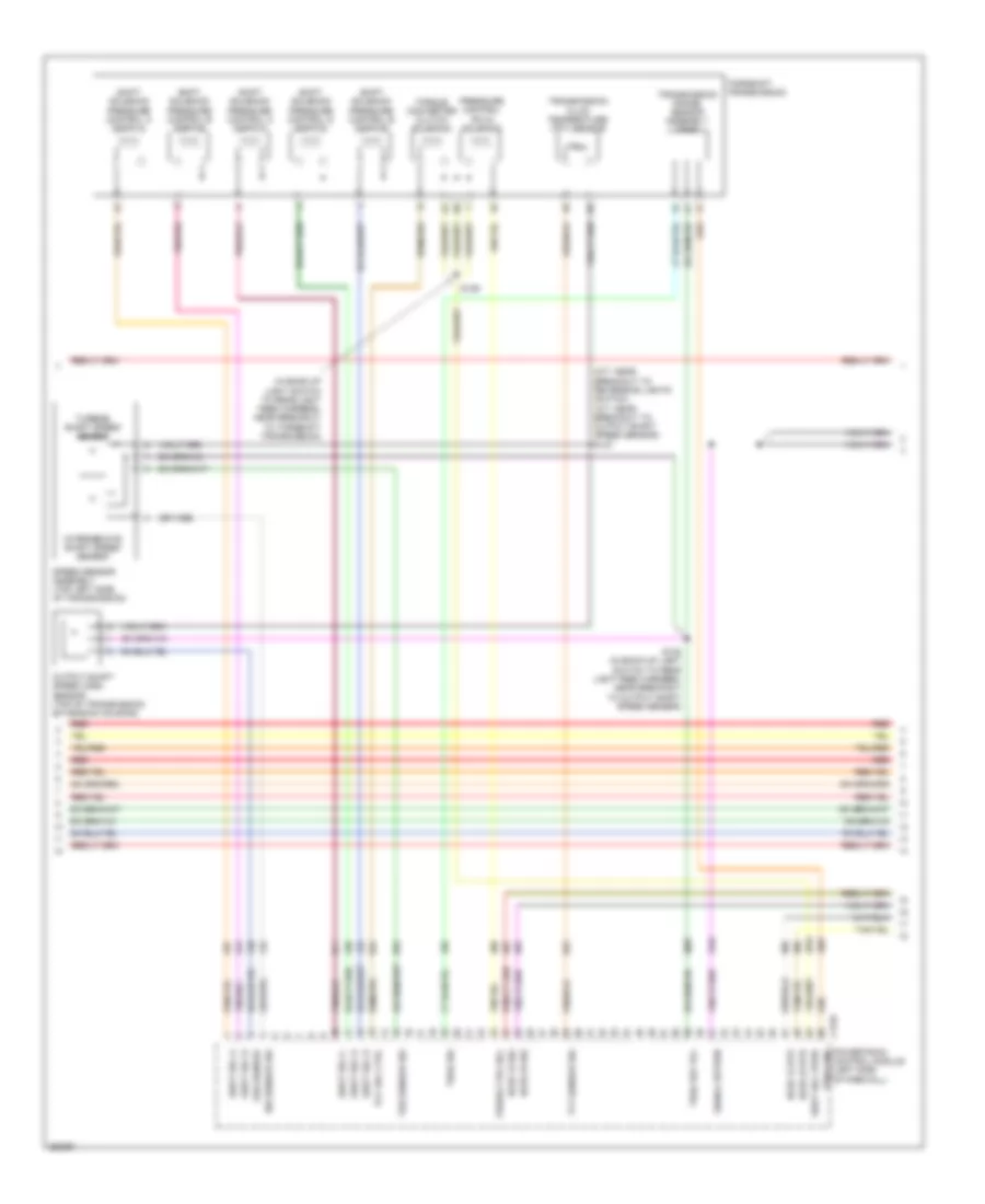
6.0L Diesel, Engine Performance Wiring Diagram (4 of 5) for Ford Cab & Chassis F350 Super Duty 2007
List of elements for 6.0L Diesel, Engine Performance Wiring Diagram (4 of 5) for Ford Cab & Chassis F350 Super Duty 2007:
- (a/t)
- (in back-up lamp switch to rear lamp feed harness, in breakout to torqshift transmission)
- (in back-up light switch to rear light feed harness, near breakout to output shaft speed sensor)
- (in back-up light switch to rear light feed harness, near breakout to torqshift transmission)
- (m/t)
- A/t
- C1381e
- C270a
- Central junction box (cjb) (behind lower left side of dash)
- Clutch pedal position switch (behind left side of dash, above clutch pedal)
- Fuse 15a
- Hot in run
- Intermediate shaft speed sensor
- Iss sig
- M/t
- Nca
- Oss sig
- Output shaft speed sensor (top of transmission extension housing)
- Pc sol pwr
- Pc-a sol
- Powertrain control module (left side of engine compt)
- Pressure control (pc-a) solenoid
- Red
- Ref volt
- Rev lmp ctrl
- Reversing lamp relay
- S127
- S128
- S129
- S235
- Shift solenoid pressure control a (sspc-a)
- Shift solenoid pressure control b (sspc-b)
- Shift solenoid pressure control c (sspc-c)
- Shift solenoid pressure control d (sspc-d)
- Shift solenoid pressure control e (sspc-e)
- Sig rtn
- Speed sensor assembly (top left side of transmission)
- Sspc-a crl
- Sspc-b ctrl
- Sspc-c crl
- Sspc-d ctrl
- Sspc-e ctrl
- Tcc sol ctrl
- Tft sens sig
- Torqshift transmission
- Torque converter clutch solenoid
- Tow/haul switch
- Tr-p sig
- Transmission fluid temperature sensor
- Transmission range sensor assembly (tr-p)
- Tss sig
- Turbine shaft speed sensor
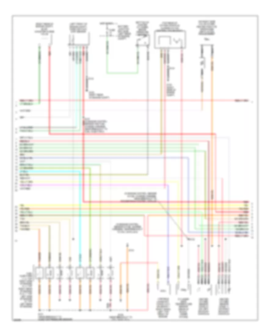
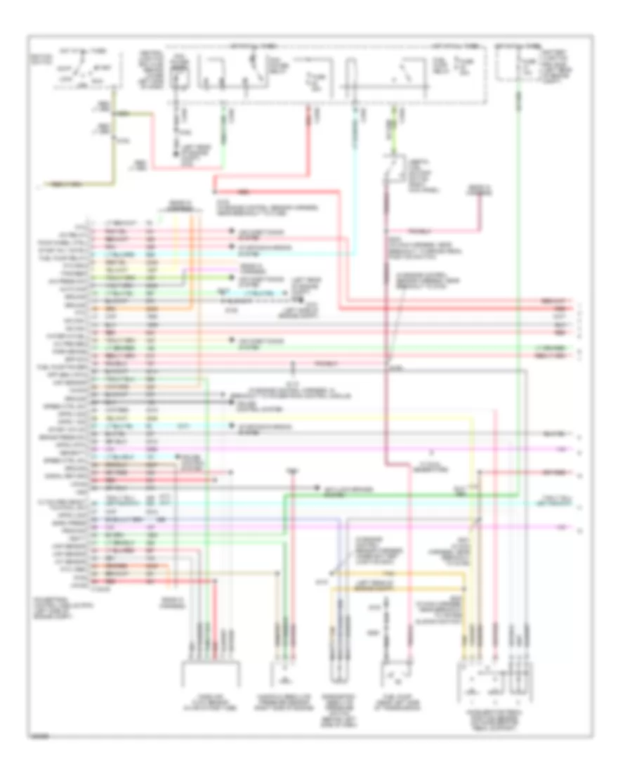
6.0L Diesel, Engine Performance Wiring Diagram (5 of 5) for Ford Cab & Chassis F350 Super Duty 2007
List of elements for 6.0L Diesel, Engine Performance Wiring Diagram (5 of 5) for Ford Cab & Chassis F350 Super Duty 2007:
- (in engine control sensor & fuel charge harness, near breakout to engine coolant temperature sensor)
- (not used)
- (top rear center of engine) injection pressure regulator
- (top right front of engine) glow plug control module
- Battery
- C1273a
- C1273b
- C1381t
- Can bus 2h
- Can bus 2l
- Charge
- Charge (2nd)
- Ckp sensor
- Cmp sensor
- Coolant temp
- Cooling fan
- Cooling fans system
- Ebp sensor
- Egr valve
- Egr valve actuator (top of engine)
- Engine coolant temperature sensor (front of engine)
- Engine oil temperature sensor (top right of engine)
- Eot sensor
- Exhaust back pressure sensor (left front of engine)
- Fan clutch
- Ficm comm
- Ficm cyl id
- Ficm delivery
- Ficm to pcm connections (from diagram 1 of 5)
- Generator
- Glow plug
- Glow plug 1
- Glow plug 2
- Glow plug 3
- Glow plug 4
- Glow plug 5
- Glow plug 6
- Glow plug 7
- Glow plug 8
- Glow plug sys
- Ground
- Hot at all times
- Icp sensor
- Injection control pressure sensor (top left rear of engine)
- Ipr control
- Left glow plug bank
- Manifold air temperature sensor (top left front of engine)
- Mat sensor
- Nca
- Pcm pwr rly
- Plug rly
- Powertrain control module (pcm) (left side of engine compt)
- Red
- Ref voltage
- Right glow plug bank
- S147
- S190
- S192
- S193 (in engine control sensor & fuel charge harness, near breakout to exhaust back pressure sensor)
- Secondary generator
- Signal return
- Turbo act
- Variable geometric turbo actuator
- W/ dual generators
6.8L
6.8L, Engine Performance Wiring Diagram (1 of 5) for Ford Cab & Chassis F350 Super Duty 2007
List of elements for 6.8L, Engine Performance Wiring Diagram (1 of 5) for Ford Cab & Chassis F350 Super Duty 2007:
- (in engine control sensor & fuel charge harness, near breakout to powertrain control module)
- A/c clutch rly ctrl
- A/c press sw sig
- Air conditioning system
- Brake press sw in
- C175a
- Camshaft position sensor (front of right cylinder bank)
- Canister purge valve
- Ckp sensor +
- Ckp sensor -
- Cmp sensor 1 sig
- Coil on plug
- Coil on plug 1
- Coil on plug 10
- Coil on plug 2
- Coil on plug 3
- Coil on plug 4
- Coil on plug 5
- Coil on plug 6
- Coil on plug 7
- Coil on plug 8
- Coil on plug 9
- Crankshaft position sensor (on lower front center of engine)
- Cyl hd temp sens sig
- Etc motor
- Fuel inj 1 control
- Fuel inj 10 control
- Fuel inj 2 control
- Fuel inj 3 control
- Fuel inj 4 control
- Fuel inj 5 control
- Fuel inj 6 control
- Fuel inj 7 control
- Fuel inj 8 control
- Fuel inj 9 control
- Fuel rail press sen
- Fuel rail temp sens
- Ho2s 11 htr
- Ho2s 11 input
- Ho2s 21 htr
- Ho2s 21 input
- Iat sensor signal
- Ignition transformer capacitor 1 (top right front of engine)
- Ignition transformer capacitor 2 (top front of left cylinder head)
- Imtv cntrl
- Injection pressure sensor (ips) (top left of intake manifold)
- Knock sensor 1 +
- Knock sensor 1 -
- Knock sensor 2 +
- Knock sensor 2 -
- Maf sensor sig rtn
- Maf sensor signal
- Nca
- Powertrain control module (left side of firewall)
- Red/
- Reference voltage
- S145
- S147 (in engine control sensor & fuel charge harness, near breakout to injector pressure sensor)
- Shield drain wire
- Signal return
- Tan
- Tan/red
- Throttle position sensor (tps) (on throttle body)
- Tps 1 sig
- Tps 2 sig
- Tps ref voltage
- Tps sig return
6.8L, Engine Performance Wiring Diagram (2 of 5) for Ford Cab & Chassis F350 Super Duty 2007
List of elements for 6.8L, Engine Performance Wiring Diagram (2 of 5) for Ford Cab & Chassis F350 Super Duty 2007:
- (bottom of master cylinder) brake pressure switch
- (in engine control sensor & fuel charge harness, near breakout to powertrain control module)
- (left front of engine compt) mass air flow (maf) sensor
- (right rear of engine compt) evap canister purge valve
- (top right of engine) intake manifold tuning valve (imtv)
- Battery junction box (bjb) (left rear of engine compt)
- Cylinder head temperature sensor (on left cylinder head)
- Fuel injectors (1, 2, 5: top right side of engine) (3, 4: top right rear of engine) (6, 7: top left side of engine) (8: top left rear of engine) (9, 10: top left of engine)
- Fuse 2a
- G102 (right rear of engine compt)
- Heated oxygen sensor (ho2s) 11 (on right exhaust manifold)
- Heated oxygen sensor (ho2s) 21 (on left exhaust manifold)
- Hot in run
- Nca
- Red
- S127 (m/t: near breakout to reversing lights switch) (a/t: near breakout to output shaft speed sensor)
- S131 (near breakout to injector pressure sensor)
- S132
- S136 (near breakout to coil on plug 3)
- Tan
- Tan/red
6.8L, Engine Performance Wiring Diagram (3 of 5) for Ford Cab & Chassis F350 Super Duty 2007
List of elements for 6.8L, Engine Performance Wiring Diagram (3 of 5) for Ford Cab & Chassis F350 Super Duty 2007:
- (in back-up light switch to rear light feed harness, near breakout to torqshift transmission)
- (m/t: near breakout to reversing lights switch) (a/t: near breakout to output shaft speed sensor) s127
- C175c
- Ho2s 12 htr
- Ho2s 12 sig
- Ho2s 22 htr
- Ho2s 22 sig
- Intermediate shaft speed sensor
- Iss sensor sig
- Oss sensor sig
- Output shaft speed sensor (top of transmission extension housing)
- Powertrain control module (left side of firewall)
- Pr ctrl sol
- Pressure control (pc-a) solenoid
- Red
- S128 (in back-up light switch to rear light feed harness, near breakout to output shaft speed sensor)
- S129
- Shift sol a
- Shift sol b
- Shift sol c
- Shift sol d
- Shift sol e
- Shift sol vpwr
- Shift solenoid pressure control a (sspc-a)
- Shift solenoid pressure control b (sspc-b)
- Shift solenoid pressure control c (sspc-c)
- Shift solenoid pressure control d (sspc-d)
- Shift solenoid pressure control e (sspc-e)
- Sig rtn
- Speed sensor assembly (top left side of transmission)
- Tcc sol ctrl
- Tft sensor sig
- Torqshift transmission
- Torque converter clutch (tcc) solenoid
- Tr sens sig
- Transmission fluid temperature sensor
- Transmission range sensor assembly (tr-p)
- Trs ground
- Trs ref voltage
- Tss sensor sig
- Turbine shaft speed sensor
6.8L, Engine Performance Wiring Diagram (4 of 5) for Ford Cab & Chassis F350 Super Duty 2007
List of elements for 6.8L, Engine Performance Wiring Diagram (4 of 5) for Ford Cab & Chassis F350 Super Duty 2007:
- (a/t: near breakout to output shaft speed sensor) (m/t: near breakout to transfer case assembly)
- (in fuel tank) fuel tank unit
- (near breakout to brake pedal position switch)
- (not used) c145
- Brake pedal position switch (above brake pedal)
- C270a
- C270f
- Central junction box (cjb) (behind lower left side of dash)
- Check engine ind
- Computer data lines system
- Dual knock sensor (right rear of cylinder head)
- Electronic throttle control (etc) motor (on throttle body)
- From pcm power relay (diagram 5 of 5)
- Fuel pump driver module (left rear frame rail)
- Fuel pump relay
- Fuse 10a
- Fuse 15a
- Fuse 20a
- G102 (right rear of engine compt)
- G401 (at left side of vehicle underbody)
- Heated oxygen sensor (ho2s) 12 (catalyst monitor) (rear of catalytic converter)
- Heated oxygen sensor (ho2s) 22 (catalyst monitor) (left side of transmission)
- Hot at all times
- Hot in on or start
- Hot in run
- Hs can +
- Hs can -
- Inertia fuel shut-off (ifs) switch (right kick panel)
- Instrument cluster
- Nca
- Red
- Red/
- Return
- S106
- S138
- S205
- S208
- S234
- Tow/haul switch
- W/ narrow frame
- W/ wide frame
6.8L, Engine Performance Wiring Diagram (5 of 5) for Ford Cab & Chassis F350 Super Duty 2007
List of elements for 6.8L, Engine Performance Wiring Diagram (5 of 5) for Ford Cab & Chassis F350 Super Duty 2007:
- (in breakout to c140)
- (in engine control sensor harness, in breakout to c140) s122
- (in engine control sensor harness, near breakout to c1756) s123
- (in engine control sensor harness, near grommet in dash panel) s111
- (in main harness, near breakout to brake pedal position switch) s258
- (near breakout to air bag sliding contact)
- (near breakout to c2186) s221
- (not used)
- (right rear of engine compt) g102
- (wire end)
- Acc
- Accelerator pedal position (app) sensor (on accelerator pedal support)
- Air conditioning system
- Anti-lock brakes system
- App sensor 1 sig
- App sensor 2 sig
- App sensor 3 pwr
- App sensor 3 rtn
- App sensor 3 sig
- Atn sig
- Battery junction box (bjb) (left rear of engine compartment)
- Bpp sw
- C175b
- C270c
- C270f
- C270h
- C281b
- Canister vent ctrl
- Central junction box (cjb) (behind lower left side of dash)
- Computer data lines system
- Cpd sw sig
- Cpsi sw sig
- Cruise control system
- Evap canister vent control solenoid (left rear side of engine compt)
- Exterior lights system
- Four- wheel drive control module (behind right side of dash)
- Fpump drvr mod
- Ftp sensor
- Fuel tank pressure (ftp) sensor (above left side of rear axle)
- Fuse 10a
- Fuse 20a
- G100 (left rear of engine compt)
- G102 (right rear of engine compt)
- Ground
- Heated oxygen sensor (ho2s) 13 (w/ narrow frame) (under left front of vehicle)
- Ho2s 13 input
- Ho2s 13 rtn
- Hot at all times
- Hs can +
- Hs can -
- Ignition switch
- Lock
- Nca
- Off
- Park sig
- Pcm power diode
- Pcm power relay
- Pcm pwr rly
- Pnk
- Power
- Powertrain control module (left side of firewall)
- Programming sig
- Pto
- Pto engage
- Pto status
- Red
- Red/pnk
- Rev lmp rly ctrl
- Run
- S106
- S164
- S223
- S412 (except regular cab) (in taillamps harness, near breakout to c140)
- Signal return
- Signal rtn
- Speed ctrl sw in
- Speed ctrl sw rtn
- Start
- Starter relay ctrl
- Starting/ charging system
- Starting/charging system
- Tach ouput
- Tan
- To fuel pump relay (diagram 4 of 5)
- Tow/haul sw sig
- Vems system sig
- Voltage ref
- Vss
- Vss sig
- W/ narrow frame red/pnk
- W/ wide frame
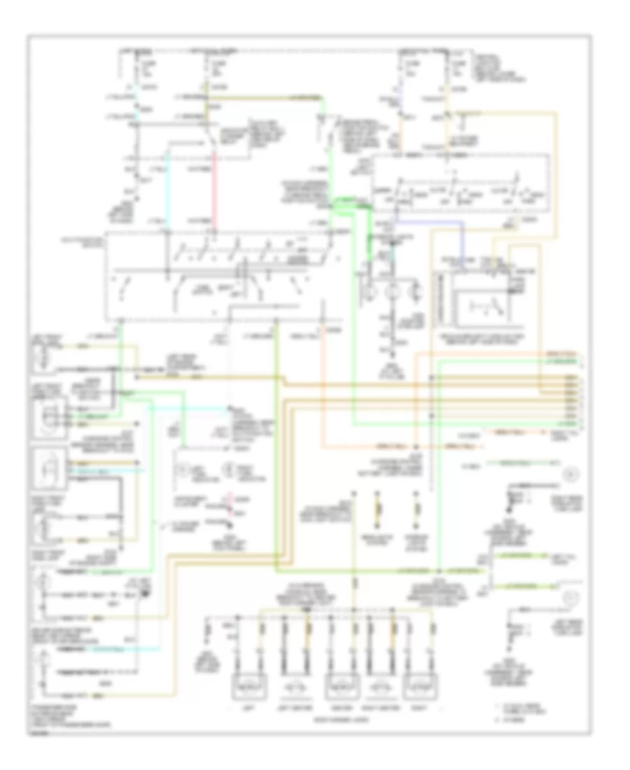
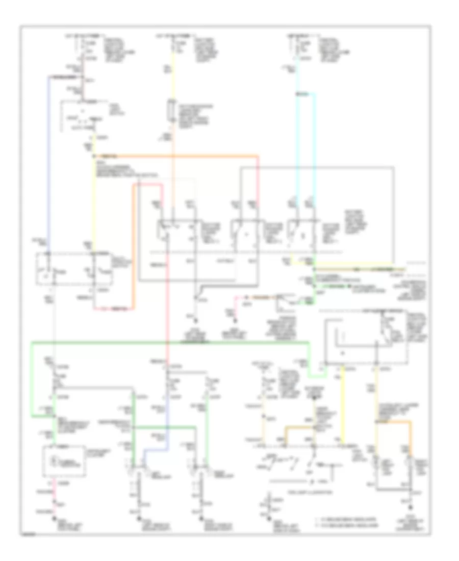
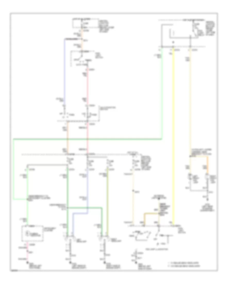
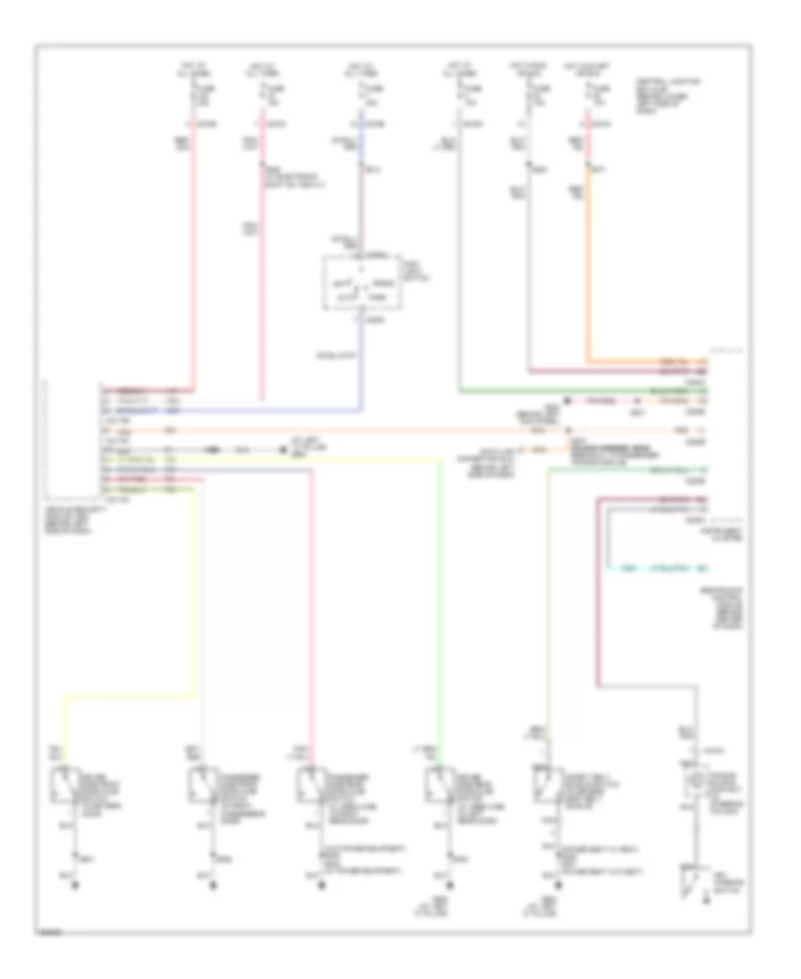
EXTERIOR LIGHTS
Exterior Lamps & Trailer Connector Wiring Diagram (1 of 3) for Ford Cab & Chassis F350 Super Duty 2007
List of elements for Exterior Lamps & Trailer Connector Wiring Diagram (1 of 3) for Ford Cab & Chassis F350 Super Duty 2007:
- (at left "c" pillar) g900
- (in main harness, near breakout to brake pedal position switch) s240
- (in overhead console, near breakout to center roof marker light) s921
- (left rear of engine compartment) g100
- (near breakout to ignition switch)
- Auto
- Auxiliary relay box 1 (behind left center of dash)
- Brake pedal position switch (behind left side of dash, above brake pedal)
- C202a
- C202b
- C205a
- C2113b
- C220a
- C220b
- C270a
- C270b
- Center
- Central junction box (cjb) (behind lower left side of dash)
- Driver side exterior rear view mirror (front of driver's door)
- Fuse 15a
- Fuse 20a
- Fuse 30a
- G108 (right side of engine compt)
- G201 (behind left side of dash)
- G202 (behind left side of dash)
- G300 (behind left kick panel)
- G400 (on vehicle underbody, rear chassis left side member)
- G900 (at left "c" pillar)
- Hazard switch
- Head
- Headlights system
- High mounted stoplamp
- Hot at all times
- Hot in run
- Indicator flasher relay
- Instrument cluster
- Interior lights system
- Left
- Left center
- Left front park/turn lamp
- Left front side lamp
- Left rear park/stop/ turn lamp
- Left tail lamps
- Left turn indicator
- Main light switch
- Microprocessor
- Multi-function switch
- Nca
- Off
- Others
- Park
- Park lamp relay
- Passenger side exterior rear view mirror (front of passenger's door)
- Right
- Right center
- Right front park/turn lamp
- Right front side lamp
- Right rear park/stop/ turn lamp
- Right tail lamps
- Right turn indicator
- Roof marker lamps
- S102
- S104 (in engine control sensor harness, in breakout to battery junction box)
- S105 (in engine control harness, under battery junction box)
- S107 (in engine control sensor harness, near breakout to g100)
- S180
- S201
- S206
- S207
- S214
- S215 (in main harness, near breakout to main light switch)
- S217
- S249
- S272
- S300
- S402
- S404
- S501
- S639
- S904
- Switch)
- Turn switch
- Vehicle security module (vsm) (behind left side of dash)
- W/ box
- W/ dual rear wheel & w/ box
- W/ power equipment
- W/ power mirrors
- W/o box
Exterior Lamps & Trailer Connector Wiring Diagram (2 of 3) for Ford Cab & Chassis F350 Super Duty 2007
List of elements for Exterior Lamps & Trailer Connector Wiring Diagram (2 of 3) for Ford Cab & Chassis F350 Super Duty 2007:
- (diesel) s162 s106 (gasoline)
- (in rear lamp connector harness) s417
- (not used)
- Battery junction box (bjb) (left rear of engine compt)
- C270b
- C270f
- C270h
- C270j
- Central junction box (cjb) (behind lower left side of dash)
- Diesel
- Fuse 20a
- G100 (left rear of engine compt)
- G400 (on vehicle underbody, rear chassis left side member)
- Gasoline
- Hot at all times
- Left license plate lamp
- Left rear park/stop/ turn lamp
- Left rear side lamp 1
- Left rear side lamp 2
- Left tail lamps
- Left turn trailer tow relay
- Nca
- Parking lamp trailer tow relay
- Rear marker lamp assembly
- Right license plate lamp
- Right rear park/stop/ turn lamp
- Right rear side lamp 1
- Right rear side lamp 2
- Right tail lamps
- Right turn trailer tow relay
- S103
- S162
- S319 (in body main harness, near breakout for g300)
- S402
- S404
- S407
- S408
- S409
- S410
- S418
- S463
- W/ dual rear wheels
- W/ rear bumper
- W/o box
- W/o dual rear wheels
- W/o rear bumper
Exterior Lamps & Trailer Connector Wiring Diagram (3 of 3) for Ford Cab & Chassis F350 Super Duty 2007
List of elements for Exterior Lamps & Trailer Connector Wiring Diagram (3 of 3) for Ford Cab & Chassis F350 Super Duty 2007:
- (in trailer lamp feed harness, near breakout to 7-pin trailer tow connector)
- (left side of rear bumper) trailer tow connector (4 pin)
- (left side of rear bumper) trailer tow connector (7 pin)
- (not used)
- 1792
- Battery charge trailer tow relay
- Battery junction box (bjb) (left rear of engine compt)
- Brake pressure transducer
- C1381b
- C175b
- C2142a
- C2142b
- C270a
- C270b
- C270e
- C270f
- C270g
- Central junction box (cjb) (behind lower left side of dash)
- Chassis cab
- Computer data lines system
- Diesel
- Except chassis cab
- Fuse 10a
- Fuse 15a
- Fuse 20a
- Fuse 30a
- G100 (diesel) (left rear of engine compt)
- G102 (gasoline) (right rear of engine compt)
- G201 (behind left side of dash)
- G202 (behind left side of dash)
- G400 (on vehicle underbody, rear chassis left side member)
- Gasoline
- Hi can -
- Hi can+
- Hot at all times
- Hot in run
- Hot in run or start
- Pcm power diode
- Pcm power relay
- Pnk
- Powertrain control module (gasoline: on left side of firewall) (diesel: left side of engine compt)
- Red
- S106 (gasoline)
- S121 (in main harness, in breakout to c211)
- S160 (in engine control harness, under battery junction box)
- S162 (diesel)
- S218
- S290
- S413 (in taillamps harness, near breakout to c140)
- S430
- S431
- S432
- S433 (in trailer lamp feed harness, near to breakout 7-pin trailer tow connector)
- Sig rtn
- Trailer brake control (tbc) connector
- Trailer brake control (tbc) module (behind center of dash)
- Trailer tow reversing lamp relay
- Vbatt
- Vpwr
- W/ brake control module
- W/o brake control module
5.4L
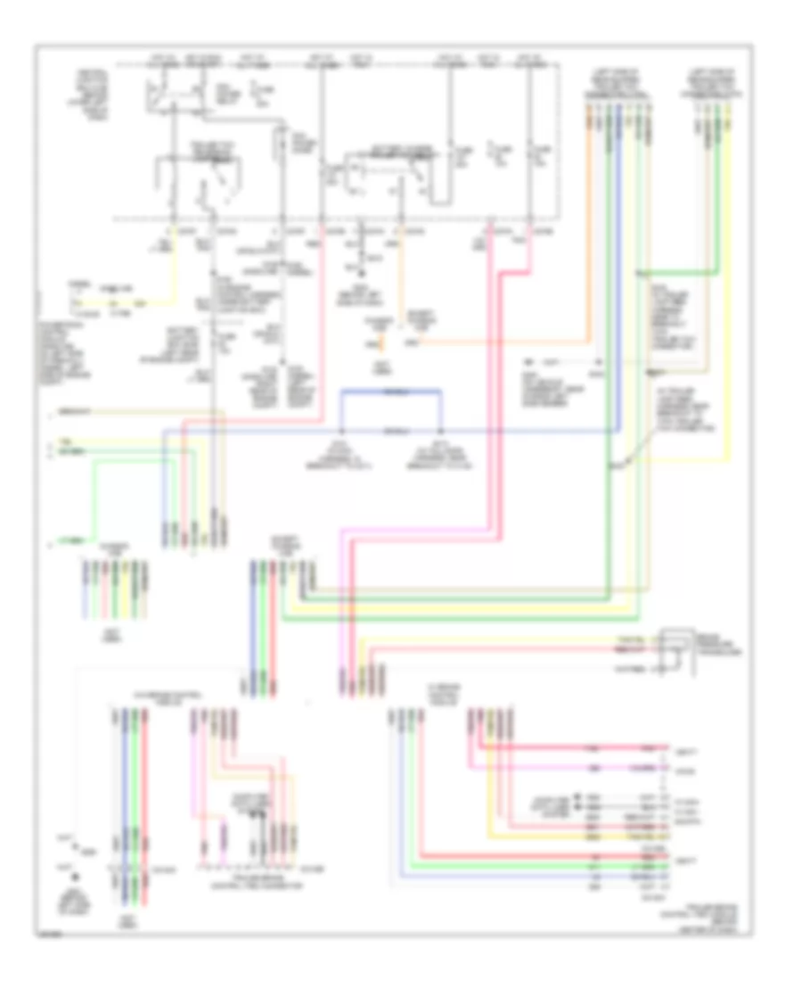
5.4L, Back-up Lamps Wiring Diagram for Ford Cab & Chassis F350 Super Duty 2007
List of elements for 5.4L, Back-up Lamps Wiring Diagram for Ford Cab & Chassis F350 Super Duty 2007:
- (not used)
- (others) s404
- A/t
- Battery junction box (bjb) (left rear of engine compt)
- C145
- C175b
- C270f
- C270g
- C4099
- Central junction box (cjb) (behind lower left side of dash)
- Chassis cab
- Electrochromatic inside mirror unit
- Except chassis cab
- Fuse 10a
- Fuse 15a
- G100 (left rear of engine compt)
- G102 (right rear of engine compt)
- G400 (on vehicle underbody, rear chassis left side member)
- Hot at all times
- Hot in run or start
- If equipped
- Left reversing lamp
- M/t
- Nca
- Others
- Parking aid
- Parking aid module (pam) (right kick panel)
- Pcm power diode
- Pcm power relay
- Powertrain control module (pcm) (left side of firewall)
- Reversing lamp relay
- Reversing lamps switch (on top left side of trans- mission)
- Right reversing lamp
- S106
- S133 (in engine control sensor harness, under battery junction box)
- S211 (in main harn, near breakout to c264)
- S250
- S402
- S426 (in rear lamp connector harness)
- S426 (in tail lamps harness, near breakout to c423)
- To left tail lamps
- To right tail lamps
- Trailer tow connector (7 pin) (left side of rear bumper)
- W/ electrochromatic mirror
6.0L DIESEL
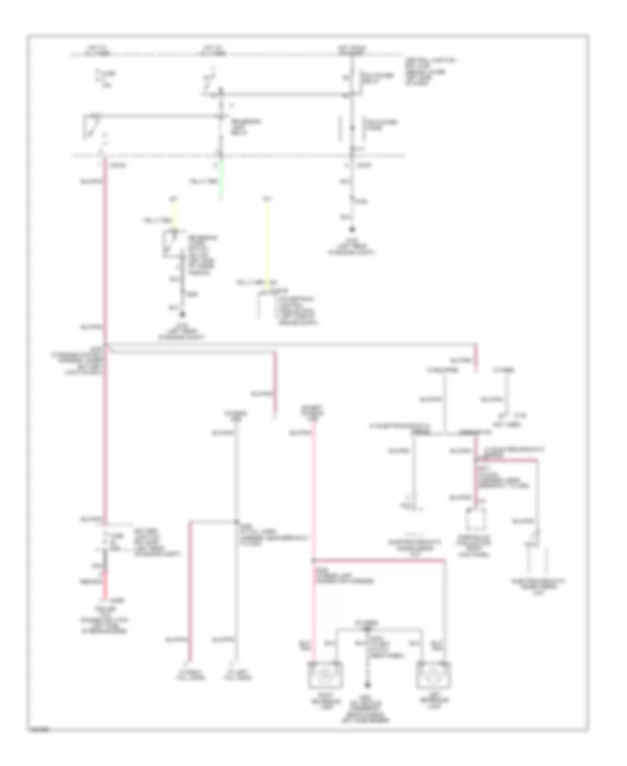
6.0L Diesel, Back-up Lamps Wiring Diagram for Ford Cab & Chassis F350 Super Duty 2007
List of elements for 6.0L Diesel, Back-up Lamps Wiring Diagram for Ford Cab & Chassis F350 Super Duty 2007:
- (not used)
- (others) s404
- A/t
- Battery junction box (bjb) (left rear of engine compt)
- C1381b
- C145
- C270f
- C270g
- C4099
- Central junction box (cjb) (behind lower left side of dash)
- Chassis cab
- Electrochromatic inside mirror unit
- Except chassis cab
- Fuse 10a
- Fuse 15a
- G100 (left rear of engine compt)
- G400 (on vehicle underbody, rear chassis left side member)
- Hot at all times
- Hot in run or start
- If equipped
- Left reversing lamp
- M/t
- Nca
- Others
- Parking aid
- Parking aid module (pam) (right kick panel)
- Pcm power diode
- Pcm power relay
- Powertrain control module (pcm) (left side of engine compt)
- Red/pnk
- Reversing lamp relay
- Reversing lamps switch (on top left side of trans- mission)
- Right reversing lamp
- S160 (in engine control harness, under battery junction box)
- S162
- S211 (in main harness, near breakout to c264)
- S250
- S402 (w/ box & dual rear wheel)
- S426 (in rear lamp connector harness)
- S426 (in tail lamps harness, near breakout to c423)
- To left tail lamps
- To right tail lamps
- Trailer tow connector (7 pin) (left side of rear bumper)
- W/ electrochromatic mirror
6.8L
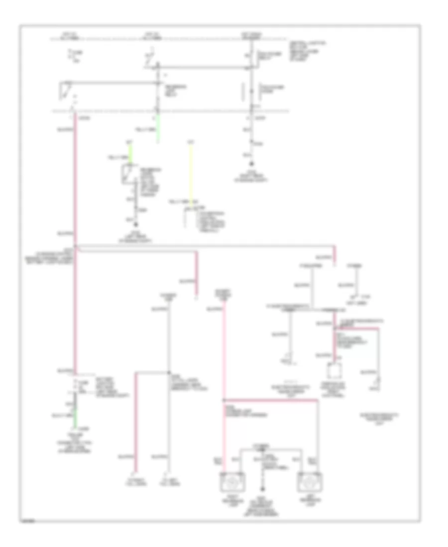
6.8L, Back-up Lamps Wiring Diagram for Ford Cab & Chassis F350 Super Duty 2007
List of elements for 6.8L, Back-up Lamps Wiring Diagram for Ford Cab & Chassis F350 Super Duty 2007:
- (not used)
- (others) s404
- A/t
- Battery junction box (bjb) (left rear of engine compt)
- C145
- C175b
- C270f
- C270g
- C4099
- Central junction box (cjb) (behind lower left side of dash)
- Chassis cab
- Electrochromatic inside mirror unit
- Except chassis cab
- Fuse 10a
- Fuse 15a
- G100 (left rear of engine compt)
- G102 (right rear of engine compt)
- G400 (on vehicle underbody, rear chassis left side member)
- Hot at all times
- Hot in run or start
- If equipped
- Left reversing lamp
- M/t
- Nca
- Others
- Parking aid
- Parking aid module (pam) (right kick panel)
- Pcm power diode
- Pcm power relay
- Powertrain control module (pcm) (left side of firewall)
- Reversing lamp relay
- Reversing lamps switch (on top left side of trans- mission)
- Right reversing lamp
- S106
- S133 (in engine control sensor harness, under battery junction box)
- S211 (in main harn, near breakout to c264)
- S250
- S402
- S426 (in rear lamp connector harness)
- S426 (in tail lamps harness, near breakout to c423)
- To left tail lamps
- To right tail lamps
- Trailer tow connector (7 pin) (left side of rear bumper)
- W/ electrochromatic mirror
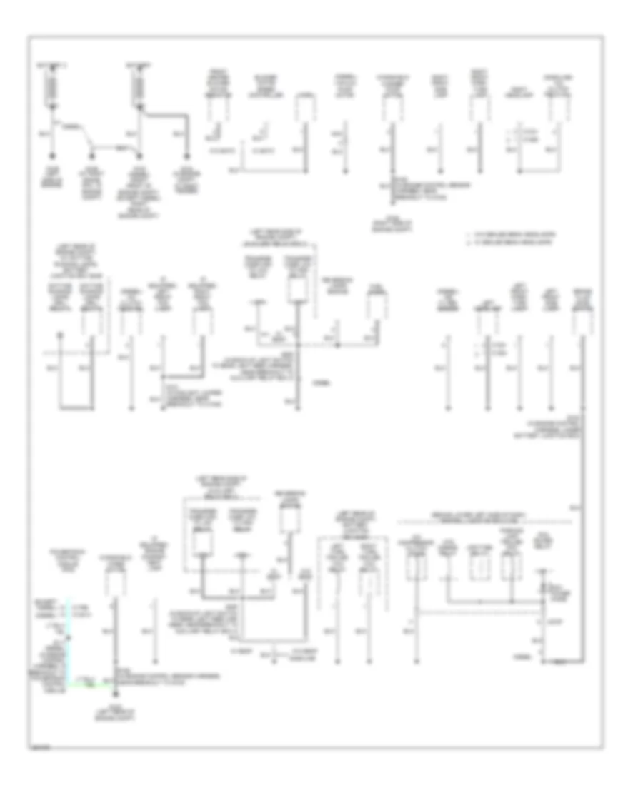
GROUND DISTRIBUTION
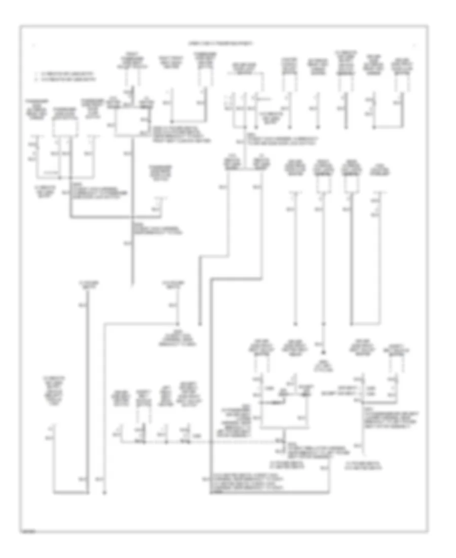
Ground Distribution Wiring Diagram (1 of 7) for Ford Cab & Chassis F350 Super Duty 2007
List of elements for Ground Distribution Wiring Diagram (1 of 7) for Ford Cab & Chassis F350 Super Duty 2007:
- (behind lower left side of dash) central junction box (cjb)
- (diesel)
- (diesel) a/c clutch field coil
- (diesel) air filter sensor
- (except diesel)
- (gasoline) a/c clutch field coil
- (if equipped) engine compart- ment lamp
- (if equipped) left front fog lamp
- (if equipped) right front fog lamp
- (left rear of engine compt) (w/ daytime running lamps) battery junction box (bjb)
- (left rear of engine compt) battery junction box (bjb)
- (left rear side of engine compt) auxiliary relay box 3
- 87a
- A/c compressor clutch diode
- Battery
- Battery 2
- Blower motor speed controller
- Brake fluid level switch
- C1021
- C1041
- C1284
- C1285
- C1381a
- C175b
- C270f
- Daytime running lamps (drl) relay 2
- Daytime running lamps (drl) relay 3
- Diesel
- Front heater blower motor resistor
- Fuel pump
- G100 (left rear of engine compt)
- G102 (diesel) (right front of engine compt) (except diesel) (right rear of engine compt)
- G104 (in engine compt, at right fender)
- G106 (at right frame rail, in engine compt)
- G108 (right side of engine compt)
- G109 (left side of engine)
- Gasoline
- Harness, near breakout to g108)
- Horn
- Htd mirror relay
- Left front park/ turn lamp
- Left front side lamp
- Left headlamp
- Left turn trailer tow relay
- Nca
- Parking lamp trailer tow relay
- Pcm power diode
- Pcm power relay
- Powertrain control module (pcm)
- Reversing lamps switch
- Right front park/ turn lamp
- Right front side lamp
- Right headlamp
- Right turn trailer tow relay
- S101 (in foglight jumper harness, near breakout to c1045)
- S102 (in engine control harness, under battery junction box)
- S117 (diesel) (in engine control harness, in breakout to powertrain control module)
- S250 (in back-up light switch to rear light feed har- ness, near breakout to auxiliary relay box 3)
- S250 (in back-up light switch to rear light feed harness, near breakout to auxiliary relay box 3)
- Transfer case high to low relay
- Transfer case low to high relay
- Upfitter relay
- Vacuum pump motor
- W/ eatc
- W/ esof
- W/ sealed beam headlamps
- W/o eatc
- W/o esof
- W/o sealed beam headlamps
- Windshield washer pump motor
- Windshield wiper motor
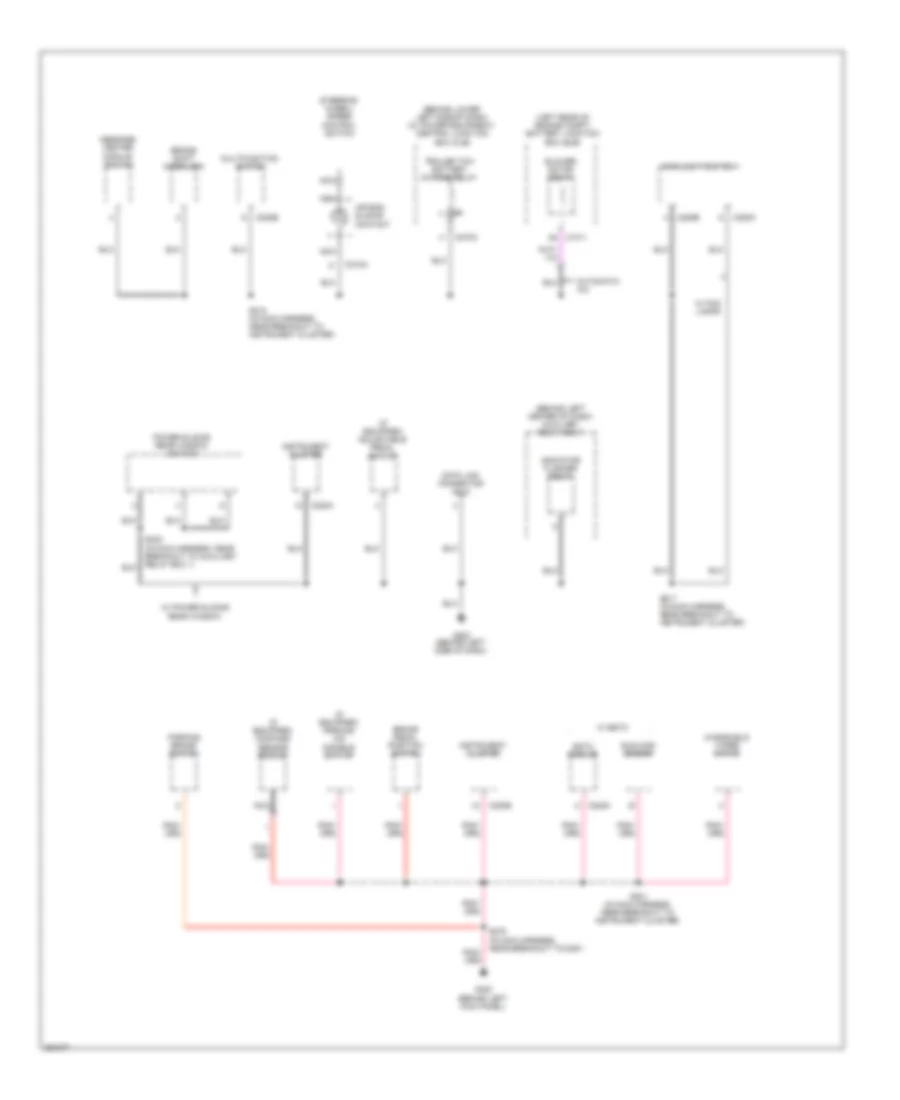
Ground Distribution Wiring Diagram (2 of 7) for Ford Cab & Chassis F350 Super Duty 2007
List of elements for Ground Distribution Wiring Diagram (2 of 7) for Ford Cab & Chassis F350 Super Duty 2007:
- (behind left center of dash) auxiliary relay box 1
- (behind lower left side of dash) (w/ power equipment) central junction box (cjb)
- (if equipped) adjustable pedal switch
- (if equipped) compass sensor module
- (if equipped) parking aid disable switch
- (left rear of engine compt) battery junction box (bjb)
- Air bag sliding contact
- Automatic a/c
- Blower motor relay
- Brake pedal position switch
- Brake shift interlock
- C1011
- C202b
- C205a
- C205b
- C218a
- C220a
- C220b
- C228a
- C270a
- Data link connector (dlc)
- Eatc module
- G202 (behind left side of dash)
- G300 (behind left kick panel)
- Indicator flasher relay
- Instrument cluster
- Main light switch
- Message center module switch
- Multifunction switch
- Nca
- Parking brake switch
- Power sliding rear window switch
- S201 (in main harness, near breakout to instrument cluster)
- S217 (in main harness, near breakout to instrument cluster)
- S218 (in main harness, near breakout to instrument cluster)
- S232 (in main harness, near breakout to auxiliary relay box 1)
- S278 (in main harness, near breakout to c291)
- Steering wheel/ speed control switch
- Sunload sensor
- Trailer tow battery charge relay
- W/ eatc
- W/ fog lamps
- W/ power sliding rear window
- Windshield wiper motor
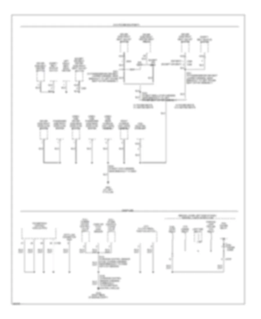
Ground Distribution Wiring Diagram (3 of 7) for Ford Cab & Chassis F350 Super Duty 2007
List of elements for Ground Distribution Wiring Diagram (3 of 7) for Ford Cab & Chassis F350 Super Duty 2007:
- (5.4l) charge motion control valve (cmcv)
- (6.8l) intake manifold tuning valve (imtv)
- (behind lower left side of dash) central junction box (cjb)
- (crew cab) driver side rear door ajar switch
- (crew cab) passenger side rear door ajar switch
- (crew cab) rear interior/ map lamps assembly
- (except sir seat)
- (except sir seat) driver side front seat adjust switch
- (gasoline)
- (m/t) clutch pedal position switch
- (sir seat)
- (w/o power equipment)
- C175b
- C270f
- C360
- C369
- Data link connector (dlc)
- Driver side front door ajar switch
- Driver side front heated seat relay
- Driver side front seat adjust switch
- Driver side seat heater switch
- Except sir seat
- Front interior/ map lamps assembly
- Fuel pump relay
- G102 (right rear of engine compt)
- G900 (at left "c" pillar)
- High mounted stoplamp
- Htd mirror relay
- Left front seat back heater
- Mass air flow (maf) sensor
- Nca
- Parking lamp trailer tow relay
- Passenger side front door ajar switch
- Pcm power diode
- Pcm power relay
- Powertrain control module (pcm)
- S106 (in engine control sensor harness, in breakout to powertrain control module)
- S300 (in body main harness, near breakout to g900)
- S301 (in passenger-driver seat jumper harness, near breakout to left power seat motor assembly)
- S332 (in seat regulator harness, near breakout to left power seat motor assembly)
- Safety belt buckle switch
- Sir seat
- Upfitter relay
- W/ power seats, w/ heated seats
- W/ power seats, w/o heated seats
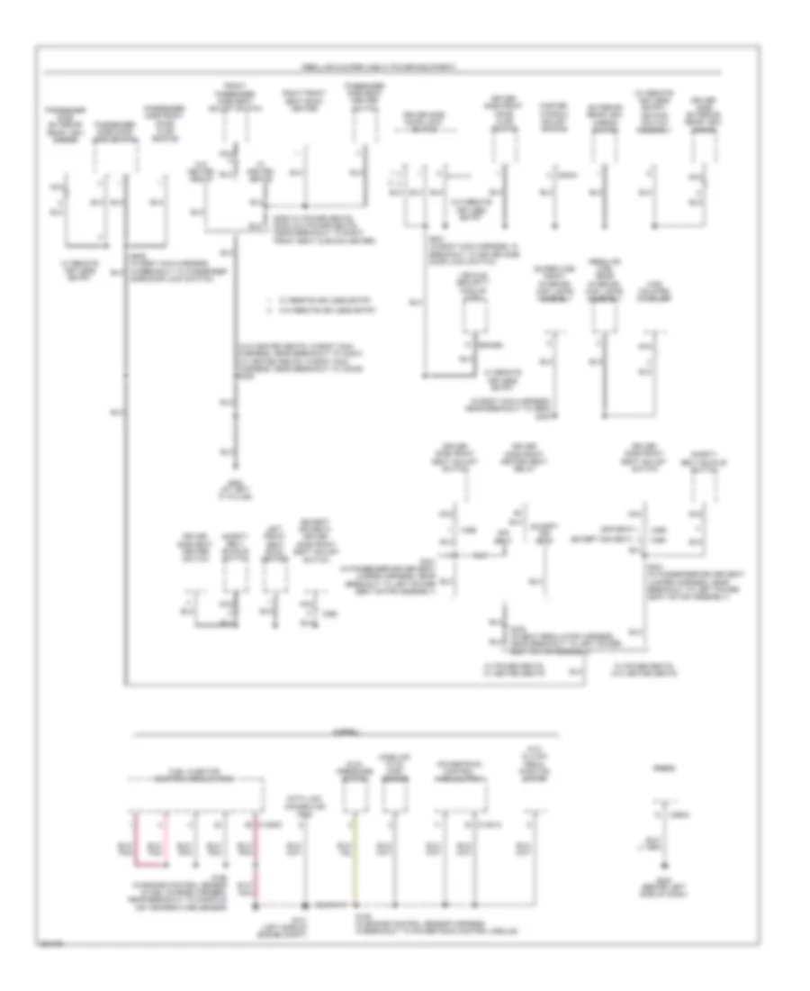
Ground Distribution Wiring Diagram (4 of 7) for Ford Cab & Chassis F350 Super Duty 2007
List of elements for Ground Distribution Wiring Diagram (4 of 7) for Ford Cab & Chassis F350 Super Duty 2007:
- (diesel)
- (except sir seat)
- (except sir seat) driver side front seat adjust switch
- (in body main harness, near breakout to g900) s300
- (m/t) clutch pedal position switch
- (regular & super cab w/ power equipment)
- (regular cab) rear interior/ map lamps assembly
- (sir seat)
- (super cab) front interior/ map lamps assembly
- (w/ remote keyless entry) keypad switch assembly
- (w/o heated seats: in body main harness, near breakout to c3007) (w/ heated seats: in body main harness, near breakout to c3049) s306
- C1381a
- C1388c
- C2113a
- C290a
- C360
- C369
- C504a
- Data link connector (dlc)
- Driver side door lock switch
- Driver side exterior rear view mirror
- Driver side front door ajar switch
- Driver side front heated seat relay
- Driver side front seat adjust switch
- Driver side seat heater switch
- Dual pressure switch
- Except sir seat
- Exterior rear view mirror switch
- Front passenger side seat adjust switch
- Fuel injector control module (ficm)
- G101 (left side of engine compt)
- G200 (behind left side of dash)
- G900 (at left "c" pillar)
- High mounted stoplamp
- Left front seat back heater
- Mass air flow (maf) sensor
- Master window adjust switch
- Nca
- Passenger side door lock switch
- Passenger side exterior rear view mirror
- Passenger side front door ajar switch
- Passenger side seat heater switch
- Powertrain control module (pcm)
- Radio
- Right front seat back heater
- S106 (in engine control sensor harness, in breakout to powertrain control module)
- S195 (in engine control sensor & fuel charge harness, near breakout to manifold air temperature sensor)
- S301 (in passenger-driver seat jumper harness, near breakout to left power seat motor assembly)
- S332 (in seat regulator harness, near breakout to left power seat motor assembly)
- S355 (w/ power seats) s335 (w/o power seats) (near breakout to right front seat cushion heater)
- S501 (in body main harness, in breakout to driver side door lock switch)
- Safety belt buckle switch
- Side door lock switch)
- Sir seat
- Vehicle security module (vsm)
- W/ heated seats
- W/ power seats, w/ heated seats
- W/ power seats, w/o heated seats
- W/ remote keyless entry
- W/o heated seats
- W/o remote keyless entry
Ground Distribution Wiring Diagram (5 of 7) for Ford Cab & Chassis F350 Super Duty 2007
List of elements for Ground Distribution Wiring Diagram (5 of 7) for Ford Cab & Chassis F350 Super Duty 2007:
- (crew cab w/ power equipment)
- (except sir seat)
- (except sir seat) driver side front seat adjust switch
- (sir seat)
- (w/ heated seats: in body main harness, near breakout to c3007) s306
- (w/ remote
- (w/ remote keyless entry) keypad switch assembly
- C360
- C369
- Driver side door lock switch
- Driver side exterior rear view mirror
- Driver side front door ajar switch
- Driver side front heated seat relay
- Driver side front seat adjust switch
- Driver side rear door ajar switch
- Driver side seat heater switch
- Except sir seat
- Exterior rear view mirror switch
- Front interior/ map lamps assembly
- Front passenger side seat adjust switch
- G900 (at left "c" pillar)
- High mounted stoplamp
- Keyless entry)
- Left front seat back heater
- Master window adjust switch
- Nca
- Passenger side door lock switch
- Passenger side exterior rear view mirror
- Passenger side front door ajar switch
- Passenger side rear door ajar switch
- Passenger side seat heater switch
- Rear interior/ map lamps assembly
- Right front seat back heater
- S300 (in body main harness, near breakout to g900)
- S301 (in passenger- driver seat jumper harness, near breakout to left power seat motor assembly)
- S301 (in passenger-driver seat jumper harness, near breakout to left power seat motor assembly)
- S326 (in body main harness, near breakout to c340)
- S332 (in seat regulator harness, near breakout to left power seat motor assembly)
- S355 (w/ power seats) s335 (w/o power seats) (near breakout to right front seat cushion heater)
- S501 (in body main harness, in breakout to driver side door lock switch)
- S639 (in body main harness, in breakout to passenger side door lock switch)
- Safety belt buckle switch
- Sir seat
- Vehicle security module (vsm)
- W/ heated seats
- W/ power seats
- W/ power seats, w/ heated seats
- W/ power seats, w/o heated seats
- W/ remote keyless entry
- W/o heated seats
- W/o power seats
- W/o remote keyless entry
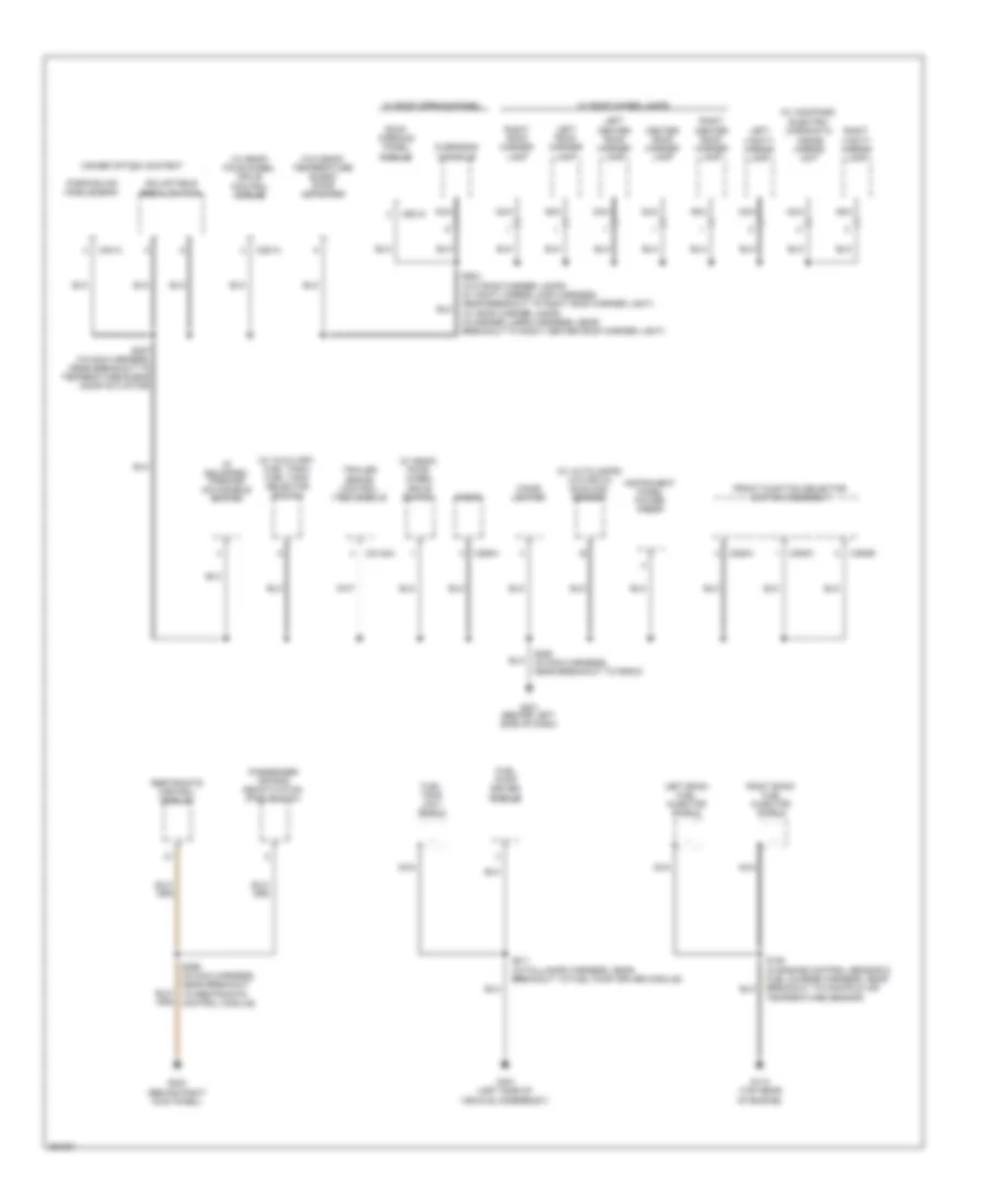
Ground Distribution Wiring Diagram (6 of 7) for Ford Cab & Chassis F350 Super Duty 2007
List of elements for Ground Distribution Wiring Diagram (6 of 7) for Ford Cab & Chassis F350 Super Duty 2007:
- (if equipped) parking aid disable switch
- (w/ autolamps) (w/o eatc) sunload sensor
- (w/ auxiliary fuel tank) fuel tank selector switch
- (w/ compass) electro- chromatic inside mirror unit
- (w/ esof) four- wheel drive switch
- (w/ esof) four-wheel drive control module
- (w/o esof) temperature blend door actuator
- Adjustable pedal switch
- C2142a
- C281a
- C290a
- C294a
- C294b
- C294c
- C4014
- C921a
- Center roof marker lamp
- Cigar lighter
- Front function selector switch assembly
- Fuel pump driver module
- Fuel tank unit shield
- G110 (top rear of engine)
- G201 (behind left side of dash)
- G203 (behind right kick panel)
- G401 (left side of vehicle underbody)
- Higher option content
- Instrument panel power point
- Left bank fuel injector shield
- Left center roof marker lamp
- Left roof marker lamp
- Left vanity mirror lamp
- Nca
- Overhead console
- Parking aid module (pam)
- Passenger air bag deactivation (pad) switch
- Radio
- Restraints control module
- Right bank fuel injector shield
- Right center roof marker lamp
- Right roof marker lamp
- Right vanity mirror lamp
- Roof opening panel module
- S194 (in engine control sensor & fuel charge harness, near breakout to manifold air temperature sensor)
- S257 (in main harness, near breakout to temperature blend door actuator)
- S290 (in main harness, near breakout to radio)
- S299 (in main harness, near breakout to restraints control module)
- S411 (in taillamps harness, near breakout to fuel pump driver module)
- S904 (w/o roof marker lamps: in vanity mirror lamp harness, near breakout to right roof marker light) (w/ roof marker lamps: in marker lamps harness, near breakout to right center roof marker light)
- Trailer brake control (tbc) module
- W/ roof maker lamps
- W/ roof opening panel
Ground Distribution Wiring Diagram (7 of 7) for Ford Cab & Chassis F350 Super Duty 2007
List of elements for Ground Distribution Wiring Diagram (7 of 7) for Ford Cab & Chassis F350 Super Duty 2007:
- (w/ rear bumper) left license plate lamp
- (w/ rear bumper) right license plate lamp
- Abs control module
- Chassis cab or dual fuel tanks or 200 plus wheel base
- Connector harness)
- Dual rear wheels, flareside
- Except chassis cab or dual fuel tanks or 200 plus wheel base
- G105 (left front of engine compt)
- G400 (on vehicle underbody, rear chassis left side member)
- Left front running board lamp
- Left rear park/ stop/ turn lamp
- Left rear running board lamp
- Left rear side lamp 1
- Left rear side lamp 2
- Left reversing lamp
- Left tail lamps
- Nca
- Rear marker lamp assembly
- Right front running board lamp
- Right rear park/ stop/ turn lamp
- Right rear running board lamp
- Right rear side lamp 1
- Right rear side lamp 2
- Right reversing lamp
- Right tail lamps
- S313 (in running board lamps harness, near breakout to right rear running board light)
- S401 (in taillamps harness, near breakout to g400)
- S402
- S404 (in rear lamp connector harness)
- S409
- S410
- S432 (in trailer lamp feed harness, near breakout to 7-pin trailer tow connector )
- S463
- Trailer tow connector
- Trailer tow connector 4-pin
- Trailer tow connector 7-pin
- W/ lighted running boards
- W/ single rear wheels
- W/o box
HEADLIGHTS
Autolamps Wiring Diagram, with DRL for Ford Cab & Chassis F350 Super Duty 2007
List of elements for Autolamps Wiring Diagram, with DRL for Ford Cab & Chassis F350 Super Duty 2007:
- (automatic a/c) (manual a/c)
- (in foglight jumper harness, near breakout to c1045) s100
- (near breakout to g100)
- 6.0l
- 87a
- Air conditioning system
- Auto
- Battery junction box (bjb) (left rear of engine compt)
- C202a
- C205a
- C2113b
- C220a
- C220b
- C270a
- C270b
- C270f
- C270g
- C270h
- Central junction box (cjb) (behind lower left side of dash)
- Central junction box (cjb) (behind lower left side of dash)
- Daytime running lamps (drl) relay 1
- Daytime running lamps (drl) relay 2
- Daytime running lamps (drl) relay 3
- Daytime running lamps (drl) resistor (on left front side of engine compt)
- Engine controls system
- Exterior lights system
- Fog
- Fog lamp illumination
- Fog lamp relay
- Fuse 10a
- Fuse 15a
- Fuse 30a
- G100 (left rear of engine compartment)
- G100 (left rear of engine compt)
- G108 (right side of engine compt)
- G201 (manual a/c) (behind left side of dash)
- G202 (behind left side of dash)
- G300 (automatic a/c) (behind left kick panel)
- G300 (behind left kick panel)
- Head
- Headlamp relay
- Hi-beam indicator
- Hot at all times
- Hot in run
- Hot in start or run
- Instrument cluster
- Instrument cluster system
- Left front fog lamp
- Left headlamp
- Main light switch
- Microprocessor
- Multi- function switch
- Off
- Park
- Parking brake switch (behind left side of dash, on park brake assembly)
- Pass
- Right front fog lamp
- Right headlamp
- S101
- S102
- S113
- S124
- S180
- S201
- S201 s290
- S203 (near breakout to instrument cluster)
- S214
- S217
- S244 (in main harness, near breakout to brake pedal position switch)
- S272
- S278
- S287
- Sunload sensor (top center of dash)
- To g100)
- Vehicle security module (vsm) (behind left side of dash)
- W/ sealed beam headlamps
- W/o sealed beam headlamps
Autolamps Wiring Diagram, without DRL for Ford Cab & Chassis F350 Super Duty 2007
List of elements for Autolamps Wiring Diagram, without DRL for Ford Cab & Chassis F350 Super Duty 2007:
- (in junction box wiring harness, near breakout for left front fog light) s110
- 87a
- Battery junction box (bjb) (left rear corner of engine compartment)
- C270b
- C270c
- C270e
- Central junction box (cjb) (behind left side of dash)
- Daytime running lamps relay
- Flash
- Fog lamps
- Fuse 10a
- Fuse 15a
- Fuse 20a
- Fuse 7.5a
- G100 (left front of engine compt)
- G102 (right front of engine compt)
- G103 (left side of engine compt)
- G203 (at right ``a" pillar)
- G204 (at left "a" pillar)
- G204 (at left ``a" pillar)
- High
- High beam ind
- High beam relay
- Hot at all times
- Hot in start or run
- Illumination
- Instrument cluster
- Left front fog lamp
- Left head- lamp
- Low beam
- Low beam relay
- Main light switch
- Multi-function switch
- Neutral
- Off
- Park
- Red
- Right front fog lamp
- Right head- lamp
- S109
- S118
- S121
- S206
- S212
- W/ fog lamps
Headlamps Wiring Diagram, with DRL for Ford Cab & Chassis F350 Super Duty 2007
List of elements for Headlamps Wiring Diagram, with DRL for Ford Cab & Chassis F350 Super Duty 2007:
- (in foglight jumper harness, near breakout to c1045) s100
- (near breakout to g100)
- 87a
- Auto
- Battery junction box (bjb) (left rear of engine compt)
- C1381a
- C202a
- C205a
- C220a
- C220b
- C270a
- C270b
- C270f
- C270g
- C270h
- Central junction box (cjb) (behind lower left side of dash)
- Central junction box (cjb) (behind lower left side of dash)
- Daytime running lamps (drl) relay 1
- Daytime running lamps (drl) relay 2
- Daytime running lamps (drl) relay 3
- Daytime running lamps (drl) resistor (on left front side of engine compt)
- Exterior lights system
- Fog
- Fog lamp illumination
- Fog lamp relay
- Fuse 10a
- Fuse 15a
- Fuse 30a
- G100 (left rear of engine compartment)
- G100 (left rear of engine compt)
- G108 (right side of engine compt)
- G202 (behind left side of dash)
- G300 (behind left kick panel)
- Head
- Hi-beam indicator
- Hot at all times
- Hot in run
- Hot in start or run
- Instrument cluster
- Instrument cluster system
- Left front fog lamp
- Left headlamp
- Main light switch
- Multi- function switch
- Off
- Park
- Parking brake switch (behind left side of dash, on park brake assembly)
- Pass
- Powertrain control module (diesel) (left side of engine compt)
- Right front fog lamp
- Right headlamp
- S101
- S102
- S113
- S124
- S180
- S201
- S203 (near breakout to instrument cluster)
- S214
- S217
- S244 (in main harness, near breakout to brake pedal position switch)
- S272
- S278
- S287
- W/ sealed beam headlamps
- W/o sealed beam headlamps
Headlamps Wiring Diagram, without DRL for Ford Cab & Chassis F350 Super Duty 2007
List of elements for Headlamps Wiring Diagram, without DRL for Ford Cab & Chassis F350 Super Duty 2007:
- (in foglight jumper harness, near breakout to c1045) s100
- (near breakout to g100)
- (near breakout to instrument cluster) s203
- Auto
- C202a
- C205a
- C220a
- C220b
- C270a
- C270b
- C270f
- C270g
- C270h
- Central junction box (cjb) (behind lower left side of dash)
- Central junction box (cjb) (behind lower left side of dash)
- Exterior lights system
- Fog
- Fog lamp illumination
- Fog lamp relay
- Fuse 10a
- Fuse 15a
- Fuse 30a
- G100 (left rear of engine compartment)
- G100 (left rear of engine compt)
- G108 (right side of engine compt)
- G202 (behind left side of dash)
- G300 (behind left kick panel)
- Head
- Hi-beam indicator
- Hot at all times
- Hot in start or run
- Instrument cluster
- Left front fog lamp
- Left headlamp
- Main light switch
- Multi-function switch
- Off
- Park
- Pass
- Right front fog lamp
- Right headlamp
- S101
- S102
- S113
- S180
- S201
- S214
- S217
- S272
- W/ sealed beam headlamps
- W/o sealed beam headlamps
HORN
Horn Wiring Diagram for Ford Cab & Chassis F350 Super Duty 2007
List of elements for Horn Wiring Diagram for Ford Cab & Chassis F350 Super Duty 2007:
- Air bag sliding contact (in steering column)
- C2113b
- C218a
- C270a
- C270h
- Central junction box (cjb) (behind lower left side of dash)
- Fuse 15a
- G108 (at right side of engine compt)
- G202 (behind left side of dash)
- Horn (right front of vehicle)
- Horn relay
- Hot at all times
- Nca
- S180
- S218
- S252
- Sound system
- Steering wheel/ speed control switch
- Vehicle security module (vsm) (behind left side of dash)
- W/ remote keyless entry
INSTRUMENT CLUSTER
Instrument Cluster Wiring Diagram (1 of 2) for Ford Cab & Chassis F350 Super Duty 2007
List of elements for Instrument Cluster Wiring Diagram (1 of 2) for Ford Cab & Chassis F350 Super Duty 2007:
- 4wd high ind
- 4wd low ind
- Abs ind
- Air bag ind
- Air filter ind
- Anti-theft on ind
- Battery saver relay
- Brake fluid level switch (diesel: on brake fluid reservoir) (except diesel: in brake fluid reservoir)
- C205b
- C220a
- C220b
- C270a
- C270b
- C270d
- Central junction box (cjb) (behind lower left side of dash)
- Charge ind
- Check engine ind
- Computer data lines system
- Engine coolant temperature
- Exterior lights system
- Fuel gauge
- Fuse 10a
- Fuse 15a
- G100 (left rear of engine compt)
- G202 (behind left side of dash)
- G300 (behind left kick panel)
- Headlights system
- High beam ind
- Hot at all times
- Hot in run or acc
- Hot in start or run
- Illumination (6 bulbs)
- Instrument cluster
- Interior lamps relay
- Interior lights system
- Lh turn signal ind
- Low brake fluid level/ park brake ind
- Low oil pressure ind
- Low oil pressure/ high coolant temperature ind
- Main light switch
- Microprocessor
- Oil pressure switch (5.4l: on left front of engine) (6.0l: top center of engine) (6.8l: lower left side of engine)
- Rh turn signal ind
- S102
- S201
- S217
- S218
- S254
- S271
- Speed control ind
- Speedometer
- Tachometer
- Tow/ haul ind (diesel)
- Transmission fluid temperature
- Transmissions system
- Wait to start ind (diesel)
- Warning system
- Water in fuel ind
Instrument Cluster Wiring Diagram (2 of 2) for Ford Cab & Chassis F350 Super Duty 2007
List of elements for Instrument Cluster Wiring Diagram (2 of 2) for Ford Cab & Chassis F350 Super Duty 2007:
- (behind left side of dash)
- (in main harness, in breakout to instrument cluster)
- (left rear of cab) (diesel) fuel tank selector valve
- Air filter sensor (diesel) (left side of engine compt)
- C1381a
- C175b
- C270a
- Can +
- Can -
- Central junction box (cjb) (behind lower left side of dash)
- Compass sensor module (top center of front windshield)
- Computer data lines system
- Diesel
- Diesel & gasoline w/ wide frame
- Ends in harness
- Except diesel
- Fuel tank selector switch (diesel)
- Fuel tank unit
- Fuse 10a
- G100 (left rear of engine compt)
- G201
- G300 (behind left kick panel)
- Gasoline w/ narrow frame
- Headlights system
- Hot in start or run
- Info
- Interior lights system
- Message center module switch
- Nca
- Parking brake switch (behind left side of dash, on park brake assembly)
- Powertrain control module (pcm) (diesel: left side of engine compt) (except diesel: left side of firewall)
- Primary fuel sender (on fuel tank)
- Primary tank
- Red
- Reset
- S102
- S201
- S278
- S278 (in main harness, near breakout to c291)
- S290
- S298
- S400
- S901
- Secondary fuel sender (on fuel tank)
- Secondary tank
- Setup
- W/ auxiliary fuel tank
- W/o auxiliary fuel tank
Overhead Console Wiring Diagram for Ford Cab & Chassis F350 Super Duty 2007
List of elements for Overhead Console Wiring Diagram for Ford Cab & Chassis F350 Super Duty 2007:
- (behind left side of dash) g201
- C220a
- C220b
- C921a
- Close/tilt up
- G201 (behind left side of dash)
- Ground
- Hot at all times
- Instrument cluster
- Interior lamp relay
- Interior lights system
- Micro- processor
- Nca
- Open/tilt dn
- Overhead console
- Roof opening panel module (rear of roof)
- Roof opening panel, close circuit
- Roof opening panel, common
- Roof opening panel, open circuit
- S904
- S937 (in vanity mirror lamp harness, near breakout to electrochromatic inside mirror unit)
- Tan/red
INTERIOR LIGHTS
Courtesy Lamps Wiring Diagram (1 of 3) for Ford Cab & Chassis F350 Super Duty 2007
List of elements for Courtesy Lamps Wiring Diagram (1 of 3) for Ford Cab & Chassis F350 Super Duty 2007:
- Battery saver relay
- C205b
- C220a
- C220b
- C270a
- C270b
- Central junction box (cjb) (behind lower left side of dash)
- Fuse 35 10a
- Fuse 41 10a
- G201 (behind left side of dash)
- G202 (behind left side of dash)
- G400 (on vehicle underbody, rear chassis left side member)
- Hot at all times
- Instrument cluster
- Interior
- Interior lamps relay
- Left front running board lamp
- Left rear running board lamp
- Left vanity mirror lamp
- Main light switch
- Microprocessor
- Nca
- Overhead console (w/ roof opening panel)
- Right front running board lamp
- Right rear running board lamp
- Right vanity mirror lamp
- S204 (in main harness, near breakout to accelerator pedal position sensor)
- S218
- S229 (in main harness, near breakout to instrument cluster)
- S309 (in running board lamps harness, near breakout to left front running board light)
- S311
- S312 (in running board lamps harness, near breakout to right front running board light)
- S313
- S344 (in taillamps harness, near breakout to c494)
- S401
- S904
- S937 (in vanity mirror lamp harness, near breakout to electrochromatic inside mirror unit)
- To accessory delay relay (central junction box) (diagram 2 of 3)
- To rear interior/map lamps assembly (diagram 2 of 3)
- W/ lighted running boards
- W/ vanity lamps
- W/o vanity lamps
Courtesy Lamps Wiring Diagram (2 of 3) for Ford Cab & Chassis F350 Super Duty 2007
List of elements for Courtesy Lamps Wiring Diagram (2 of 3) for Ford Cab & Chassis F350 Super Duty 2007:
- (in body main harness, in breakout to front interior/map light assembly)
- Accessory delay relay
- C270a
- C270f
- C270j
- Central junction box (cjb) (behind lower left side of dash)
- Crew & super cab
- Engine compartment lamp
- From instrument cluster (diagram 1 of 3)
- From s229 (w/ vanity lamps) from instrument cluster (w/o vanity lamps) (diagram 1 of 3)
- Front interior/map lamps assembly (crew & super cab)
- G100 (left rear of engine compt)
- G900 (at left "c" pillar)
- High mounted stoplamp
- Interior
- Map
- Nca
- Rear interior/map lamps assembly (crew & regular cab)
- Regular cab
- S162
- S300
- S905 (except super cab: in body main harness, near breakout to rear interior/map light assembly) (super cab: in body main harness, near breakout to high mounted stoplight)
- S906
Courtesy Lamps Wiring Diagram (3 of 3) for Ford Cab & Chassis F350 Super Duty 2007
List of elements for Courtesy Lamps Wiring Diagram (3 of 3) for Ford Cab & Chassis F350 Super Duty 2007:
- C2113a
- C220b
- Driver's side door ajar switch (in driver's door)
- G900 (at left "c" pillar)
- Instrument cluster
- Left rear door ajar switch (w/ crew cab) (in left rear door)
- Passenger's side door ajar switch (in front passenger's door)
- Right rear door ajar switch (w/ crew cab) (in right rear door)
- S236
- S300
- S300 (w/o power equipment) s233 (w/ power equipment) s326 (w/power equipment & w/o remote keyless entry))
- S501 (w/ remote keyless entry) s326 (w/o remote keyless entry & w/ power equipment) s300 (w/o remote keyless entry & w/o power equipment)
- S639
- Vehicle security module (vsm) (behind left side of dash)
- W/ remote keyless entry
- W/o remote keyless entry
Instrument Illumination Wiring Diagram (1 of 2) for Ford Cab & Chassis F350 Super Duty 2007
List of elements for Instrument Illumination Wiring Diagram (1 of 2) for Ford Cab & Chassis F350 Super Duty 2007:
- (6 bulbs)
- Accessory delay relay
- Adjustable pedal switch (higher option content)
- Air bag sliding contact (in steering column)
- Auto
- Automatic air conditioning
- C205a
- C205b
- C2113c
- C218a
- C220a
- C228a
- C270b
- C270d
- C270i
- C270j
- C270k
- C290a
- C294b
- Central junction box (cjb) (behind lower left side of dash)
- Circuit breaker 30a
- Driver side door lock switch
- Electronic automatic temperature control (eatc) module (behind center of dash)
- Except pickup w/0 power equipment
- Exterior lights system
- Four-wheel drive switch (w/ electronic shift on the fly)
- Function selector switch assembly
- Fuse 17 15a
- Fuse 42 15a
- G201 (behind left side of dash)
- G202 (behind left side of dash)
- G2300 (left side of dash)
- G900 (at left "c" pillar)
- Head
- Hot at all times
- Instrument cluster
- Keypad switch assembly
- Main light switch
- Manual air conditioning
- Message center module switch
- Microprocessor
- Nca
- Off
- Overhead console (w/ roof opening panel)
- Park
- Parking aid disable switch (if equipped)
- Passenger side door lock switch
- Pnk
- Power sliding rear window switch
- Radio
- S215 (near breakout to main light switch)
- S216 s216 (in body main harness, in breakout to c855)
- S217
- S218
- S2300
- S232
- S272 (except pickup w/o power equipment)
- S290
- S320
- S501
- S639
- S904
- Steering wheel/speed control switch
- To master window adjust switch (diagram 2 of 2)
- Upfitter switch (if equipped)
- Vehicle security module (vsm) (behind left side of dash)
Instrument Illumination Wiring Diagram (2 of 2) for Ford Cab & Chassis F350 Super Duty 2007
List of elements for Instrument Illumination Wiring Diagram (2 of 2) for Ford Cab & Chassis F350 Super Duty 2007:
- C504a
- C504b
- From circuit breaker 601 (diagram 1 of 2)
- G900 (at left "c" pillar)
- Left rear window adjust switch (w/ crew cab)
- Master window adjust switch
- Passenger side window adjust switch (w/ crew cab)
- Passenger side window adjust switch (w/o crew cab)
- Right rear window adjust switch (w/ crew cab)
- S297 (w/o crew cab) (in body main harness, near breakout to g300)
- S328 (in body main harness, in breakout to c855)
- S501
- W/ crew cab
- W/o crew cab
NAVIGATION
Parking Assistant Wiring Diagram for Ford Cab & Chassis F350 Super Duty 2007
List of elements for Parking Assistant Wiring Diagram for Ford Cab & Chassis F350 Super Duty 2007:
- (in back-up alarm jumper harness, near breakout to c4001) s450
- C270a
- Central junction box (cjb) (behind lower left side of dash)
- Computer data lines system
- Exterior lights system
- Fuse 15a
- G201 (behind left side of dash)
- G300 (behind left kick panel.)
- Ground
- Hot in run
- Inner left signal
- Inner right signal
- Interior lights system
- Iso
- Left inner parking aid sensor (left side of rear bumper)
- Left outer parking aid sensor (left side of rear bumper)
- Outer left signal
- Outer right signal
- Pam ind
- Park aid enable
- Park aid speaker (+)
- Park aid speaker (-)
- Parking aid disable switch
- Parking aid module (pam) (at right kick panel)
- Parking aid speaker (right kick panel)
- Ref voltage
- Reverse lamps relay
- Right inner parking aid sensor (right side of rear bumper)
- Right outer parking aid sensor (right side of rear bumper)
- S201
- S206
- S257
- S290
- S451 (in back-up alarm jumper harness, near breakout to c4001)
- Sig return
- Vpwr
POWER DISTRIBUTION
Power Distribution Wiring Diagram (1 of 5) for Ford Cab & Chassis F350 Super Duty 2007
List of elements for Power Distribution Wiring Diagram (1 of 5) for Ford Cab & Chassis F350 Super Duty 2007:
- (behind lower left side of dash) central junction box (cjb)
- (in main harness, in breakout to central junction box) s249
- (in main harness, near breakout for data link connector) s242
- (in main harness, near breakout to brake pedal position switch) s214
- (in main harness, near breakout to instrument cluster) (w/ eatc) s208
- (in main harness, near breakout to restraints control module) (w/ electronic shift on the fly) s230
- (not used)
- 2 of 5)
- 30a
- Adjustable pedal switch (w/o memory)
- Auxiliary relay box 1 (behind left center of dash)
- Battery
- Battery ii (diesel)
- Brake pedal position switch
- C197b
- C202a
- C205a
- C2113b
- C2142b
- C220b
- C228b
- C270a
- C270b
- C270d
- C270e
- C270g
- C270h
- C270i
- C270j
- C270k
- C281a
- C290a
- Central junction box (cjb) (behind lower left side of dash)
- Data link connector (dlc)
- Driver side front heated seat relay
- Electronic automatic temperature control (eatc) module
- Exterior rear view mirror switch
- Four-wheel drive control module (w/ electronic shift on the fly)
- From a fuse 10 (diagram 1 of 5)
- From b fuse 16 (diagram 1 of 5)
- Front cigar lighter
- Fuse
- Fuse (not used)
- Fuse 1 15a
- Fuse 11 20a
- Fuse 111 (not used)
- Fuse 12 20a
- Fuse 13 5a
- Fuse 17 15a
- Fuse 18 20a
- Fuse 19 10a
- Fuse 2 10a
- Fuse 20 15a
- Fuse 21 20a
- Fuse 34 10a
- Fuse 4 20a
- Fuse 6
- Fuse 7 30a
- G201 (behind left side of dash)
- Indicator flasher relay
- Instru- ment panel power point
- Instrument cluster
- Main light switch
- Multi- function switch
- Nca
- Passenger side front seat adjust switch
- Pnk
- Radio
- Red
- S1000 (in engine control sensor harness, near battery) red
- S1002 (in engine control sensor harness, near battery)
- S290
- Starter motor
- To fuse (diagram 2 of 5)
- To fuse 1 (diagram 5 of 5)
- To fuse 108 (diagram 1 of 5)
- To fuse 12 (diagram 1 of 5)
- To fusible links (diagram
- To fusible links (diagram 2 of 5)
- Trailer brake control module
- Vehicle security module (vsm)
- W/ power equipment
- W/ remote keyless entry
Power Distribution Wiring Diagram (2 of 5) for Ford Cab & Chassis F350 Super Duty 2007
List of elements for Power Distribution Wiring Diagram (2 of 5) for Ford Cab & Chassis F350 Super Duty 2007:
- (behind lower left side of dash) central junction box (cjb)
- (in alternator rectifier system harness, near breakout to battery) s165
- (in alternator rectifier system harness, near breakout to secondary generator)
- (in alternator rectifier system harness, near positive battery cable)
- (in body main harness, near breakout to g300) s289
- (in engine control sensor harness, near breakout to glow plug control module) red s125
- (in main harness, in breakout to instrument cluster) s254
- (not used)
- (w/o sir seat) (w/ sir seat)
- C102a
- C1251a
- C1273a
- C1273b
- C2113b
- C2142a
- C220a
- C270a
- C270b
- C270c
- C270d
- C270e
- C270f
- C270g
- C270h
- C270i
- C270j
- C270k
- C281a
- C290a
- Central junction box (cjb) (behind lower left side of dash)
- Diesel
- Driver side door lock switch
- Driver side front seat adjust switch
- Except diesel
- Four-wheel drive control module (w/ electronic shift on the fly)
- From battery (diagram 1 of 5)
- From d fuse 112 (diagram 2 of 5)
- From fuse 111 (diagram 1 of 5)
- From ignition switch (diagram 3 of 5)
- Fuel pump relay
- Fuel tank selector switch (w/ auxiliary fuel tank, diesel only)
- Fuse
- Fuse (not used)
- Fuse (not used)
- Fuse 101 30a
- Fuse 102 30a
- Fuse 10a
- Fuse 112 30a
- Fuse 15a
- Fuse 20a
- Fuse 30a
- Fuse 33 15a
- Fuse 5a
- Fusible link e
- Fusible link h
- Generator
- Glow plug control module (gpcm)
- Horn relay
- Instrument cluster
- Nca
- Passenger side door lock switch
- Pcm power relay
- Radio
- Red
- S125 (in engine control sensor harness, near breakout to glow plug control module)
- S126 (in engine control sensor harness, near breakout to glow plug control module)
- S144
- S147 (in engine control sensor & fuel charge harness, near breakout to glow plug control module )
- S149
- S149 (in engine control sensor & fuel charge harness, near breakout to glow plug control module)
- S166 (in alternator rectifier system harness, near breakout to battery)
- Secondary generator (w/ dual generators)
- Starter relay
- To fuse (diagram 3 of 5)
- To fuse 104 (diagram 2 of 5)
- To instrument cluster (diagram 4 of 5)
- Trailer brake control module
- Upfitter relay
- Upfitter relay 1
- Upfitter relay 2
- Upfitter relay 3
- Upfitter relay 4
- Upfitter relay box (right side of dash)
- Vehicle security module (vsm)
- W/ remote keyless entry
- W/o remote keyless entry
- Windshield wiper motor
Power Distribution Wiring Diagram (3 of 5) for Ford Cab & Chassis F350 Super Duty 2007
List of elements for Power Distribution Wiring Diagram (3 of 5) for Ford Cab & Chassis F350 Super Duty 2007:
- (in engine control harness, near breakout for g100) s182
- (in engine control sensor & fuel charge harness, near breakout to fuel injector 3) s135
- (in engine control sensor harness, under battery junction box)
- (in main harness, near breakout to brake pedal position switch) s260
- (in main harness, near breakout to ignition switch) s210
- (in main harness, near breakout to instrument cluster) s271
- (in main harness, near breakout to restraints control module) s202
- (not used)
- 5.4l
- 6.8l
- Abs control module
- Acc
- Battery charge trailer tow relay
- Battery junction box (bjb) (left rear of engine compt)
- Brake pressure switch
- C1388c
- C220a
- C270a
- C270b
- C270c
- C270e
- C270f
- C281a
- Central junction box (cjb) (behind lower left side of dash)
- Clutch pedal position switch (m/t, diesel)
- Coil on plug (cop) 1
- Coil on plug (cop) 10
- Coil on plug (cop) 2
- Coil on plug (cop) 3
- Coil on plug (cop) 4
- Coil on plug (cop) 5
- Coil on plug (cop) 6
- Coil on plug (cop) 7
- Coil on plug (cop) 8
- Coil on plug (cop) 9 (6.8l)
- Compass sensor module
- Diesel
- Electro- chromatic inside mirror unit
- Fog lamp relay
- Four wheel drive control module (w/ electronic shift on the fly)
- From e fuse 115 (diagram 2 of 5)
- Fuel injector driver module (ficm)
- Fuse
- Fuse 103 30a
- Fuse 107 20a
- Fuse 10a
- Fuse 110 30a
- Fuse 116 30a
- Fuse 25
- Fuse 26 10a
- Fuse 2a
- Fuse 38 20a
- Fuse 39 15a
- Fuse 45 10a
- Fuse 8 20a
- Gasoline
- Htd mirror relay
- Ignition switch
- Ignition transformer capacitor 1
- Ignition transformer capacitor 2
- Instrument cluster
- Lock
- Nca
- Off
- Parking lamp trailer tow relay
- Passenger air bag deactivation (pad) switch
- Pcm power relay
- Red/
- Restraints control module
- Reversing lamps relay
- Run
- S108
- S130 (in engine control sensor & fuel charge harness, near breakout to injector pressure sensor)
- S258 (in main harness, near breakout to brake pedal position switch)
- Start
- Tan/ red
- To accessory delay relay (diagram 4 of 5)
- To fuse 27 (diagram 4 of 5)
- To fuse 31 (diagram 2 of 5)
- To fuse 48 (diagram 2 of 5)
Power Distribution Wiring Diagram (4 of 5) for Ford Cab & Chassis F350 Super Duty 2007
List of elements for Power Distribution Wiring Diagram (4 of 5) for Ford Cab & Chassis F350 Super Duty 2007:
- (in body main harness, in breakout to central junction box) s209
- (in body main harness, in breakout to front interior/map light assembly)
- (in body main harness, near breakout to g300) (w/o crew cab) s297
- (in engine control harness, near breakout for g100) s124
- (in main harness, near breakout to air bag sliding contact) s206
- (in main harness, near breakout to auxiliary relay box 1)
- (in main harness, near breakout to sunload sensor) (w/ power sliding rear window) s219
- (not used)
- Accessory delay relay
- All others
- Auxiliary relay box 1 (behind left center of dash)
- Battery charge trailer tow relay
- Battery junction box (bjb) (left rear of engine compt)
- Battery saver relay
- Blower motor relay
- Brake shift interlock
- C2142b
- C220a
- C220b
- C228b
- C270a
- C270c
- C270d
- C270f
- C270h
- C270i
- C270j
- C290a
- C294a
- C359
- Central junction box (cjb) (behind lower left side of dash)
- Daytime running lamps (drl) relay
- Diesel w/o electronic shift on the fly or drl
- Driver side door lock switch
- Driver side front heated seat module
- Electronic automatic temperature control (eatc) module
- Electronic shift on the fly (esof) solenoid
- Engine compartment lamp
- From central junction box (diagram 3 of 5)
- From fuse 35 (diagram 2 of 5)
- From fuse 41 (diagram 3 of 5)
- From ignition switch (diagram 3 of 5)
- From j fuse 25 (diagram 3 of 5)
- Front interior/ map lamps assembly (w/ crew & super cab)
- Function selector switch assembly
- Fuse 10a
- Fuse 15a
- Fuse 30a
- Gas w/ a/t & electronic shift on the fly w/o drl
- Gas w/ m/t & electronic shift on the fly w/o drl
- Htd mirror relay
- Indicator flasher relay
- Instrument cluster
- Interior lamps relay
- Left vanity mirror lamp
- Master window adjust switch
- Micro- processor
- Nca
- Overhead console (w/ roof opening panel)
- Parking aid module (pam)
- Passenger side door lock switch
- Passenger side window adjust switch (w/o crew cab)
- Pnk
- Power sliding rear window switch (if equipped)
- Radio
- Rear interior/ map lamps assembly
- Right vanity mirror lamp
- Roof opening panel module
- S229 (w/ vanity lamps) (in main harness, near breakout to instrument cluster)
- S235
- S320
- S906 (w/ crew & super cab)
- S937 (in vanity mirror lamp harness, near breakout to electro -chromatic inside mirror unit)
- Temperature blend door actuator (w/o eatc)
- Tow/ haul switch (w/ a/t)
- Trailer brake control module
- Vacuum pump motor
- Vacuum pump motor (diesel)
- W/ overhead console
- W/ power equipment
Power Distribution Wiring Diagram (5 of 5) for Ford Cab & Chassis F350 Super Duty 2007
List of elements for Power Distribution Wiring Diagram (5 of 5) for Ford Cab & Chassis F350 Super Duty 2007:
- (diesel)
- (in back up lamp switch harness, near breakout to auxiliary relay box 3) s163
- (in engine control sensor harness, in breakout for battery junction box) s103
- (in engine control sensor harness, left rear engine compartment)
- A/c clutch relay
- Abs control module
- Auxiliary relay box 3 (except diesel: left side of engine compt)
- Battery junction box (bjb) (left rear of engine compt)
- Blower motor relay
- C1381a
- C175b
- Daytime running lamps resistor
- Diesel
- Evap canister vent control solenoid
- From fusible link b (diagram 1 of 5)
- Fuel injector control module (ficm) relay
- Fuse (not used)
- Fuse 10a
- Fuse 15a
- Fuse 20a
- Fuse 30a
- Fuse 40a
- Fuse 50a
- Fuse 60a
- Fuse shunt
- Gasoline
- Left turn trailer tow relay
- Powertrain control module (pcm)
- Red
- Right turn trailer tow relay
- S164
- Transfer case high to low relay
- Transfer case low to high relay
- W/ electronic shift on the fly
- Windshield wiper motor
POWER DOOR LOCKS
Power Door Locks Wiring Diagram, with Keyless Entry for Ford Cab & Chassis F350 Super Duty 2007
List of elements for Power Door Locks Wiring Diagram, with Keyless Entry for Ford Cab & Chassis F350 Super Duty 2007:
- (behind
- (behind left kick panel) (automatic a/c) g300 g201 (manual a/c) (behind left side of dash)
- (in body main harness, in breakout to c855) s316
- (manual a/c)
- (top center of dash) sunload sensor
- (w/o heated seats: near breakout to right rear speaker) (w/ heated seats: in body main harness, near breakout to c340)
- 1/2
- 3/4
- 5/6
- 7/8
- 9/0
- Air conditioning system
- Autolamps on
- C2113a
- C2113b
- C2113c
- C270a
- C270b
- C270e
- Central junction box (cjb) (behind lower left side of dash)
- Diagnostic
- Door ajar sw
- Door lock
- Door lock out
- Door unlock
- Dr door relay
- Driver side door lock switch
- Driver side front door ajar switch (in driver's door)
- Driver side rear door ajar switch (crew cab) (in left rear door)
- Equipment)
- Ext lamp pwr
- Exterior lights system
- Fuse 10a
- Fuse 15a
- Fuse 30a
- G900 (at left "c" pillar)
- G900 (at left ``c" pillar)
- Ground
- Headlights system
- Headlmp relay
- Horn relay
- Horns system
- Hot at all times
- Interior lights system
- Key pad 1/2
- Key pad 3/4
- Key pad 7/8
- Key pad com
- Key pad illum
- Key pad switch assembly
- Left front door lock actuator (in left front door)
- Left rear door lock actuator (crew cab) (in left rear door)
- Left side of dash) data link connector (dlc)
- Lock
- Pass- enger side door lock switch
- Passenger side door lock actuator (in passenger's door)
- Passenger side front door ajar switch (in front passenger's door)
- Passenger side rear door ajar switch (crew cab) (in right rear door)
- Pnk
- Red
- Right rear door lock actuator (crew cab) (in right rear door)
- S214
- S230 (w/ electronic shift on the fly)
- S247 (in main harness, near breakout to passenger air bag module)
- S272 (w/ power equipment)
- S290 s201 (automatic a/c)
- S300
- S304
- S305 (w/ heated seats: near breakout to c3049) (w/o heated seats: near breakout to c3007)
- S306
- S315
- S318 (in body main harness, near breakout to g300)
- S329 (in body main harness, near breakout to g300)
- S501
- S639
- S705 (in left rear door harness, near c755)
- S805 (in right rear door harness, near c855)
- Sunload sens
- Unlock
- Vbatt
- Vehicle security module (vsm) (behind left side of dash)
Power Door Locks Wiring Diagram, without Keyless Entry for Ford Cab & Chassis F350 Super Duty 2007
List of elements for Power Door Locks Wiring Diagram, without Keyless Entry for Ford Cab & Chassis F350 Super Duty 2007:
- (in body main harness, in breakout to c855)
- (in right rear door harness, near c855)
- (w/o heated seats: near breakout to right rear speaker) (w/ heated seats: in body main harness, near breakout to c340) s304
- C270e
- Central junction box (cjb) (behind lower left side of dash)
- Driver side door lock switch
- Fuse 30a
- G900 (at left ``c" pillar)
- Hot at all times
- Interior lights system
- Left front door lock actuator (in left front door)
- Left rear door lock actuator (w/ crew cab) (in left rear door)
- Lock
- Passenger side door lock switch
- Pnk
- Right front door lock actuator (in passenger's door)
- Right rear door lock actuator (w/ crew cab) (in right rear door)
- S289
- S315
- S316
- S501
- S639
- S705 (in left rear door harness, near c755)
- S805
- Unlock
POWER MIRRORS
Electronic Day/Night Mirror Wiring Diagram for Ford Cab & Chassis F350 Super Duty 2007
List of elements for Electronic Day/Night Mirror Wiring Diagram for Ford Cab & Chassis F350 Super Duty 2007:
- (diesel)
- (diesel: left side of engine compt) (gasoline: left side of firewall)
- (gasoline)
- Acc
- C1381b
- C175b
- C270a
- C270c
- C270e
- C270f
- C270g
- Central junction box (cjb) (behind lower left side of dash)
- Compass sensor module (top center of front windshield)
- Electrochromatic inside mirror unit (center of front windshield)
- Fuse 10a
- Fuse 15a
- Fuse 30a
- G100 (diesel) (at left rear of engine compartment)
- G102 (gasoline) (at right rear of engine compartment)
- G201 (behind left side of dash)
- Ground
- Hot at all times
- Hot in start or run
- Ignition switch
- Lock
- Module voltage
- Nca
- Off
- Parking aid module (pam) (right kick panel)
- Pcm power diode
- Pcm power relay
- Powertrain control module (pcm)
- Red/
- Ref voltage
- Reversing lamp relay
- Run
- S106
- S162
- S258
- S901
- S904
- Start
- To c264)
Power Mirrors Wiring Diagram for Ford Cab & Chassis F350 Super Duty 2007
List of elements for Power Mirrors Wiring Diagram for Ford Cab & Chassis F350 Super Duty 2007:
- (at left "c" pillar) g900
- C270j
- Central junction box (cjb) (behind lower left side of dash)
- Defogger system
- Down
- Driver side exterior rear view mirror (front of driver's door)
- Exterior lights system
- Exterior rear view mirror switch
- Fuse 5a
- Hot at all times
- Left
- Mirror select switch
- Nca
- Passenger side exterior rear view mirror (front of passenger's door)
- Red
- Right
- S501
- S542
- S639
POWER SEATS
Adjustable Pedal Wiring Diagram for Ford Cab & Chassis F350 Super Duty 2007
List of elements for Adjustable Pedal Wiring Diagram for Ford Cab & Chassis F350 Super Duty 2007:
- 270d
- Adjustable pedal motor (in driver's footwell)
- Adjustable pedal switch
- Central junction box (cjb) (behind lower left side of dash)
- Fuse 15a
- Fwd
- G201 (behind left side of dash)
- Hot at all times
- Interior lights system
- Nca
- Rwd
- S257
Climate Control Seats Wiring Diagram for Ford Cab & Chassis F350 Super Duty 2007
List of elements for Climate Control Seats Wiring Diagram for Ford Cab & Chassis F350 Super Duty 2007:
- C270i
- C270j
- Central junction box (cjb) (behind lower left side of dash)
- Driver side front heated seat relay (in driver's seat cushion)
- Driver side seat heater switch
- Fuse 15a
- Fuse 20a
- G900 (at left "c" pillar)
- Hot at all times
- Hot in run
- Integrated restraints) s301 s332 (w/o seat integrated restraints)
- Left front seat back heater (in driver's seat back)
- Left front seat cushion heater (in driver's seat)
- Passenger side seat heater switch
- Right front seat back heater (in front passenger's seat back)
- Right front seat cushion heater (in front passenger's seat cushion)
- S209
- S327 (w/ heated seats: in seat regulator harness, near breakout to driver side seat heater switch) (w/o heated seats: in seat regulator harness, near breakout to left power seat motor assembly)
- S335
Driver Power Seat Wiring Diagram for Ford Cab & Chassis F350 Super Duty 2007
List of elements for Driver Power Seat Wiring Diagram for Ford Cab & Chassis F350 Super Duty 2007:
- (w/ seat integrated restraints) s301 s332 (w/o seat integrated restraints)
- C270i
- Central junction box (cjb) (behind lower left side of dash)
- Driver side front seat adjust switch
- Forward/rearward
- Front up/down
- Fuse 30a
- Fwd
- G900 (at left "c" pillar)
- Hot at all times
- Left power seat motor assembly (in driver's seat bottom)
- Nca
- Rear up/down
- Rwd
- St dn
- St up
- W/ sir seat
- W/o sir seat
Passenger Power Seat Wiring Diagram for Ford Cab & Chassis F350 Super Duty 2007
List of elements for Passenger Power Seat Wiring Diagram for Ford Cab & Chassis F350 Super Duty 2007:
- (at left "c" pillar)
- (crew cab)
- C270i
- Central junction box (cjb) (behind lower left side of dash)
- Forward/rearward
- Front up/down
- Fuse 30a
- Fwd
- G900
- G900 (at left "c" pillar)
- Hot at all times
- Nca
- Passenger side front seat adjust switch
- Rear up/down
- Right power seat motor assembly (in bottom of passenger's seat)
- Rwd
- S355
- St dn
- St up
- W/ heated seats
- W/o heated seats
POWER TOP/SUNROOF
Power Top/Sunroof Wiring Diagram for Ford Cab & Chassis F350 Super Duty 2007
List of elements for Power Top/Sunroof Wiring Diagram for Ford Cab & Chassis F350 Super Duty 2007:
- (behind left side of dash) g201
- Accessory delay relay
- Battery saver relay
- C220a
- C220b
- C270a
- C270d
- C921a
- Central junction box (cjb) (behind lower left side of dash)
- Circuit breaker 30a
- Close/tilt up
- Fuse 10a
- Gnd
- Hot at all times
- Instrument cluster
- Interior lights system
- Microprocessor
- Nca
- Open/tilt dn
- Overhead console
- Power windows system
- Pwr
- Red
- Roof opening panel module (rear of roof)
- Roof opening panel motor assembly
- S219
- S229 (in main harness, near breakout to instrument cluster)
- S904
- Sig rtn
- Tan/red
- Vpwr
- Vref
POWER WINDOWS
Power Windows Wiring Diagram, Crew Cab (1 of 2) for Ford Cab & Chassis F350 Super Duty 2007
List of elements for Power Windows Wiring Diagram, Crew Cab (1 of 2) for Ford Cab & Chassis F350 Super Duty 2007:
- (near breakout to instrument cluster)
- Accessory delay relay
- Battery saver relay
- C220a
- C220b
- C270a
- C270d
- C270i
- C504a
- C504b
- Central junction box (cjb) (behind lower left side of dash)
- Circuit breaker 601 30a
- Driver
- Driver side front power window motor (in driver's door)
- Fuse 2 10a
- Fuse 41 10a
- G900 (at left ``c" pillar)
- Hot at all times
- Instrument cluster
- Interior lights system
- Left rear
- Lock
- Master window adjust switch
- Microprocessor
- One- touch down
- One-touch down relay
- Passenger
- Power tops system
- Right rear
- S219
- S229
- S501
- Vpwr
Power Windows Wiring Diagram, Crew Cab (2 of 2) for Ford Cab & Chassis F350 Super Duty 2007
List of elements for Power Windows Wiring Diagram, Crew Cab (2 of 2) for Ford Cab & Chassis F350 Super Duty 2007:
- G202 (behind left side of dash)
- Interior lights system
- Left rear power window motor (in left rear door)
- Left rear window adjust switch
- Passenger side front power window motor (in passenger's door)
- Passenger side window adjust switch
- Power sliding rear window motor (center rear of cab)
- Power sliding rear window switch
- Right rear power window motor (in right rear door)
- Right rear window adjust switch
- S232
- S328 (in body main harness, in breakout to c855)
Power Windows Wiring Diagram, Except Crew Cab for Ford Cab & Chassis F350 Super Duty 2007
List of elements for Power Windows Wiring Diagram, Except Crew Cab for Ford Cab & Chassis F350 Super Duty 2007:
- Accessory delay relay
- Battery saver relay
- C220a
- C220b
- C270a
- C270d
- C270i
- Central junction box (cjb) (behind lower left side of dash)
- Circuit breaker 601 30a
- Driver
- Driver side front power window motor (in driver's door)
- Fuse 2 10a
- Fuse 41 10a
- G202 (behind left side of dash)
- G900 (at left ``c" pillar)
- Hot at all times
- Instrument cluster
- Interior lights system
- Lock
- Master window adjust switch
- Microprocessor
- One- touch down
- One-touch down relay
- Passenger
- Passenger side front power window motor (in passenger's door)
- Passenger side window adjust switch
- Power sliding rear window motor
- Power sliding rear window switch
- Power tops system
- S219
- S229
- S232
- S297
- S501
- Vpwr
RADIO
Radio Wiring Diagram for Ford Cab & Chassis F350 Super Duty 2007
List of elements for Radio Wiring Diagram for Ford Cab & Chassis F350 Super Duty 2007:
- (behind left side of dash) g202
- Air bag sliding contact (in steering column)
- Anti-lock brakes system
- C218a
- C270a
- C270d
- Central junction box (cjb) (behind lower left side of dash)
- Fuse 15a
- Fuse 20a
- Fuse 5a
- G200 (behind left side of dash)
- G201 (behind left side of dash)
- Gnd
- Hot at all times
- Hot in start
- Hot w/ acc delay relay energized
- Illum input
- Interior lights system
- Left front speaker
- Left rear speaker
- Lf speaker (+)
- Lf speaker (-)
- Lr speaker (+)
- Lr speaker (-)
- Mode
- Nca
- Next
- Pnk
- Radio
- Rf speaker (+)
- Rf speaker (-)
- Right front speaker
- Right rear speaker
- Rr speaker (+)
- Rr speaker (-)
- S218
- S290
- Sig
- Steering wheel radio switch
- Vbatt
- Vol +
- Vol -
- Vpwr
- Vref
- W/ steering wheel controls
SHIFT INTERLOCK
Shift Interlock Wiring Diagram for Ford Cab & Chassis F350 Super Duty 2007
List of elements for Shift Interlock Wiring Diagram for Ford Cab & Chassis F350 Super Duty 2007:
- Brake pedal position switch (behind left side of dash, above brake pedal)
- Brake shift interlock (on steering column)
- C270a
- Central junction box (cjb) (behind lower left side of dash)
- Fuse 27 15a
- Fuse 34 10a
- G202 (behind left side of dash)
- G300 (behind left kick panel)
- Hot at all times
- Hot in run
- S201
- S205 (near breakout to brake pedal position switch)
- S206
- S208 (w/ eatc)
- S218
STARTING/CHARGING
5.4L
5.4L, Charging Wiring Diagram for Ford Cab & Chassis F350 Super Duty 2007
List of elements for 5.4L, Charging Wiring Diagram for Ford Cab & Chassis F350 Super Duty 2007:
- Battery
- C102a
- C102b
- C220a
- C270a
- Central junction box (cjb) (behind lower left side of dash)
- Charge ind
- Fuse 45 10a
- G102 (right rear of engine compt)
- G104 (in engine compt, at right fender)
- Generator
- Hot in start or run
- Instrument cluster
- Power distribution system
- Red
- S125
- S126
- S149
- S271
- Starter motor
5.4L, Starting Wiring Diagram for Ford Cab & Chassis F350 Super Duty 2007
List of elements for 5.4L, Starting Wiring Diagram for Ford Cab & Chassis F350 Super Duty 2007:
- (right rear of engine compt)
- Acc
- Battery
- Battery junction box (bjb) (left rear of eng compt)
- C175b
- C197a
- C197b
- C270b
- C270c
- C270f
- C270g
- C270h
- Central junction box (cjb) (behind lower left side of dash)
- Charging circuit
- Clutch pedal position switch (above clutch pedal)
- Fuse 103 30a
- Fuse 113 30a
- Fuse 31 15a
- G102
- G102 (right rear of engine compt)
- G104 (in engine compt, at right fender)
- Hot at all times
- Ignition switch
- Lock
- M/t
- Off
- Pnk
- Powertrain control module (pcm) (left side of firewall)
- Red
- Run
- S1000
- S1002
- S106
- Start
- Starter motor
- Starter relay
6.0L DIESEL
6.0L Diesel, Charging Wiring Diagram, with Dual Generators for Ford Cab & Chassis F350 Super Duty 2007
List of elements for 6.0L Diesel, Charging Wiring Diagram, with Dual Generators for Ford Cab & Chassis F350 Super Duty 2007:
- Battery
- Battery ii
- C1273a
- C1273b
- C1381a
- C1381c
- C220a
- C270a
- Central junction box (cjb) (behind lower left side of dash)
- Charge ind
- Fuse 10a
- G102 (right front of engine compt)
- G104 (in engine compartment, at right fender)
- G106 (at right frame rail, in engine compt)
- G109 (left side of engine)
- Generator
- Glow plug control module (gpcm) (top right front of engine)
- Hot in start or run
- Instrument cluster
- Power distribution system
- Powertrain control module (pcm) (left side of engine compt)
- Red
- S125
- S126
- S144
- S147
- S149
- S165
- S166
- S271
- Secondary generator
- Starter motor
6.0L Diesel, Charging Wiring Diagram, without Dual Generators for Ford Cab & Chassis F350 Super Duty 2007
List of elements for 6.0L Diesel, Charging Wiring Diagram, without Dual Generators for Ford Cab & Chassis F350 Super Duty 2007:
- Battery
- Battery ii
- C1273a
- C1273b
- C220a
- C270a
- Central junction box (cjb) (behind lower left side of dash)
- Charge ind
- Fuse 10a
- G102 (right front of engine compt)
- G104 (in engine compartment, at right fender)
- G106 (at right frame rail, in engine compt)
- G109 (left side of engine)
- Generator
- Glow plug control module (gpcm) (top right front of engine)
- Hot in start or run
- Instrument cluster
- Power distribution system
- Red
- S125
- S126
- S147
- S149
- S271
- Starter motor
6.0L Diesel, Starting Wiring Diagram, A/T for Ford Cab & Chassis F350 Super Duty 2007
List of elements for 6.0L Diesel, Starting Wiring Diagram, A/T for Ford Cab & Chassis F350 Super Duty 2007:
- Acc
- Battery
- Battery ii
- Battery junction box (bjb) (left rear of engine compt)
- C1381a
- C1381b
- C197a
- C197b
- C270b
- C270c
- C270f
- C270g
- Central junction box (cjb) (behind lower left side of dash)
- Fuse 103 30a
- Fuse 113 30a
- Fuse 31 15a
- G102 (right front of engine compt)
- G104 (in eng compt, at right fender)
- G106 (at right frame rail, in engine compt)
- G109 (left side of engine)
- Ground
- Hot at all times
- Ignition switch
- Lock
- Off
- Pnk
- Power distribution system
- Powertrain control module (pcm) (left side of engine compt)
- Red
- Ref volt
- Run
- S1000 s1000
- S1002
- Sig rtn
- Start
- Starter motor
- Starter relay
- Starter rly ctrl
- Torqshift transmission
- Trs assembly sig
6.0L Diesel, Starting Wiring Diagram, M/T for Ford Cab & Chassis F350 Super Duty 2007
List of elements for 6.0L Diesel, Starting Wiring Diagram, M/T for Ford Cab & Chassis F350 Super Duty 2007:
- (left side of engine compt) g101
- Acc
- Battery
- Battery ii
- Battery junction box (bjb) (left rear of engine compt)
- C1381a
- C197a
- C197b
- C270a
- C270b
- C270c
- C270f
- C270g
- Central junction box (cjb) (behind lower left side of dash)
- Clt pedal deactivation sw
- Clt pedal starter interlock sw
- Clutch pedal position switch (above clutch pedal)
- Deactivate switch
- Fuse 103 30a
- Fuse 10a
- Fuse 113 30a
- Fuse 31 15a
- G102 (right front of engine compt)
- G104 (in engine compt, at right fender)
- G106 (at right frame rail, in engine compt)
- G109 (left side of engine)
- Hot at all times
- Hot in start or run
- Ignition switch
- Lock
- Off
- Pnk
- Power distribution system
- Powertrain control module (pcm) (left side of engine compt)
- Red
- Run
- S1000
- S1002
- S106
- S271
- Start
- Starter interlock
- Starter motor
- Starter relay
- Starter rly ctrl
6.8L
6.8L, Charging Wiring Diagram for Ford Cab & Chassis F350 Super Duty 2007
List of elements for 6.8L, Charging Wiring Diagram for Ford Cab & Chassis F350 Super Duty 2007:
- Battery
- C102a
- C102b
- C220a
- C270a
- Central junction box (cjb) (behind lower left side of dash)
- Charge ind
- Fuse 45 10a
- G102 (right rear of engine compt)
- G104 (in engine compt, at right fender)
- Generator
- Hot in start or run
- Instrument cluster
- Power distribution system
- Red
- S125
- S126
- S149
- S271
- Starter motor
6.8L, Starting Wiring Diagram for Ford Cab & Chassis F350 Super Duty 2007
List of elements for 6.8L, Starting Wiring Diagram for Ford Cab & Chassis F350 Super Duty 2007:
- (right rear of engine compt)
- Acc
- Battery
- Battery junction box (bjb) (left rear of eng compt)
- C175b
- C197a
- C197b
- C270b
- C270c
- C270f
- C270g
- C270h
- Central junction box (cjb) (behind lower left side of dash)
- Charging circuit
- Clutch pedal position switch (above clutch pedal)
- Fuse 103 30a
- Fuse 113 30a
- Fuse 31 15a
- G102
- G102 (right rear of engine compt)
- G104 (in engine compt, at right fender)
- Hot at all times
- Ignition switch
- Lock
- M/t
- Off
- Pnk
- Powertrain control module (pcm) (left side of firewall)
- Red
- Run
- S1000
- S1002
- S106
- Start
- Starter motor
- Starter relay
SUPPLEMENTAL RESTRAINTS
Supplemental Restraints Wiring Diagram for Ford Cab & Chassis F350 Super Duty 2007
List of elements for Supplemental Restraints Wiring Diagram for Ford Cab & Chassis F350 Super Duty 2007:
- (behind right kick panel) g203
- (in steering column)
- Air bag feed
- Air bag indicator
- Air bag return
- Air bag sliding contact
- C175b
- C218b
- C220a
- C270a
- Central junction box (cjb) (behind lower left side of dash)
- Computer data lines system
- Driver air bag unit
- Fuse 10a
- Fuse 15a
- Gasoline engine
- Ground
- Hot in acc or run
- Hot in run
- Hot in run or start
- Ignition
- Indicator ctrl
- Instrument cluster
- Iso bus
- Nca
- Pad ind ctrl
- Pad input
- Passenger air bag deactivation (pad) switch
- Passenger air bag module (behind right side of dash)
- Pin shorting bars engaged when harness connector is disconnected from module: (shorting bars connected between pins 3-4, 6-7 & 20-21)
- Powertrain control module (pcm) (left side of firewall)
- Restraints control module (behind center of dash)
- S271 (near breakout to instrument cluster)
- S299 (in main harness, near breakout to restraints control module)
- Shorting bar
- Tone driver
- Vems
TRANSMISSION
4WD Wiring Diagram for Ford Cab & Chassis F350 Super Duty 2007
List of elements for 4WD Wiring Diagram for Ford Cab & Chassis F350 Super Duty 2007:
- (in engine control harness, near breakout to g100) s124
- (in main harness, in breakout to instrument cluster)
- (in main harness, in breakout to instrument cluster) s254
- (in main harness, near breakout to brake pedal position switch)
- (in main harness, near breakout to brake pedal position switch) s205
- (in main harness, near breakout to instrument cluster) s271
- (in main harness, near breakout to restraints control module) s230
- (left side of engine compt) powertrain control module
- (not used)
- 4wd hi
- 4wd hi ind
- 4wd lo
- 4wd lo ind
- 4wd sw
- 87a
- Anti-lock brakes system
- Auxiliary relay box 3 (gasoline: left rear side of engine compt)
- Battery
- Battery junction box (bjb) (left rear of engine compt)
- Bpp sw
- Brake pedal position switch (behind left side of dash, above brake pedal)
- C1381a
- C175b
- C220b
- C270a
- C270h
- C281a
- C281b
- C350a
- C350b
- Central junction box (cjb) (behind lower left side of dash)
- Computer data lines system
- Data link connector (behind left side of dash)
- Diesel
- Electronic shift on the fly (esof) solenoid (right side of engine compt)
- Enc gnd rtn
- Esof sol
- Exterior lights system
- Four-wheel drive control module (behind right side of dash)
- Four-wheel drive switch
- Fuse 10a
- Fuse 15a
- Fuse 30a
- G100 (left rear of engine compt)
- G201 (behind left side of dash)
- G300 (behind left kick panel)
- Gasoline
- Ground
- Hi to lo
- Hot at all times
- Hot in run
- Hot in run or acc
- Hot in run or start
- Illum
- Instrument cluster
- Interior lights system
- Iso bus
- Lo to hi
- Mtr pos 2
- Mtr pos 3
- Mtr pos 4
- Mtr pos 5
- Neut sens
- Off
- Powertrain control module (left side of firewall)
- Pwr to enc
- Red
- Run/acc
- S111 (in engine control sensor harness, near grommet in dash panel)
- S163 (in back up lamp switch harness, near breakout to auxiliary relay box 3)
- S201 (in main harness, near breakout to instrument cluster)
- S208 (in main harness, near breakout to instrument cluster)
- S225 (in main harness, near breakout to instrument cluster)
- S250 (in back-up light switch to rear light feed harness, near breakout to auxiliary relay box 3)
- S257 (in main harness, near breakout to temperature blend door actuator)
- S259
- S268
- Sig rtn
- Transfer case assembly
- Transfer case high to low relay
- Transfer case low to high relay
- Vpwr
- Vss
5.4L
5.4L, A/T Wiring Diagram (1 of 2) for Ford Cab & Chassis F350 Super Duty 2007
List of elements for 5.4L, A/T Wiring Diagram (1 of 2) for Ford Cab & Chassis F350 Super Duty 2007:
- (4x4: in back-up lamp switch to rear lamp feed harness, near breakout to output shaft speed sensor) (m/t: in back-up lamp switch to rear lamp feed harness, near breakout to reversing lights switch)
- (6.8l: top center of engine)
- (in back-up light switch to rear light feed harness, near breakout to torqshift transmission)
- (in main harness, in breakout to data link connector)
- (top of transmission extension housing) output shaft speed (oss) sensor
- C175a
- C175b
- C175c
- C220b
- Computer data lines system
- Control module)
- Cyl head temp
- Cylinder head temperature sensor (6.8l: on left cylinder head) (5.4l: rear of block, under intake)
- Data link connector (behind left side of dash)
- Electronic throttle control motor (on throttle body)
- Engine controls system
- Etc cntrl
- Etc return
- G102 (right rear of engine compt)
- Hs can +
- Hs can -
- Iat sensor
- Instrument cluster
- Intermediate shaft speed sensor
- Iss sensor
- Maf sensor
- Mass air flow (maf) sensor (left front of engine compt)
- Oss sensor
- Pc sol
- Powertrain control module (left side of firewall)
- Pressure control (pc-a) solenoid
- Prog sig
- Red
- Ref voltage
- S109 (in engine control sensor harness, in breakout to abs control module)
- S127
- S128 (in back-up light switch to rear light feed harness, near breakout to output shaft speed sensor)
- S129
- S143 (in engine control sensor and fuel charge harness, near breakout to mass air flow sensor)
- S146
- S213 (in main harness, in breakout to data link connector)
- S220
- Shift sol
- Shift sol a
- Shift sol b
- Shift sol c
- Shift sol d
- Shift sol e
- Shift solenoid pressure control a (sspc-a)
- Shift solenoid pressure control b (sspc-b)
- Shift solenoid pressure control c (sspc-c)
- Shift solenoid pressure control d (sspc-d)
- Shift solenoid pressure control e (sspc-e)
- Signal return
- Speed sensor assembly (top left side of transmission)
- Tcc sol
- Tft sensor
- Throttle position sensor (5.4l: on throttle body)
- Torqshift transmission
- Torque converter clutch solenoid
- Tps 2 sig
- Tps output
- Tps sig
- Tps sig return
- Transmission fluid temperature sensor
- Transmission range sensor assembly (tr-p)
- Trs assembly
- Trs sensor
- Tss sensor
- Turbine shaft speed sensor
5.4L, A/T Wiring Diagram (2 of 2) for Ford Cab & Chassis F350 Super Duty 2007
List of elements for 5.4L, A/T Wiring Diagram (2 of 2) for Ford Cab & Chassis F350 Super Duty 2007:
- (in engine control sensor and fuel charge harness, near breakout to fuel injector 8) s137
- (in engine control sensor harness, in breakout to power- train control module) s106
- (in engine control sensor harness, near breakout to brake fluid level switch) s115
- (in engine control sensor harness, near breakout to c1756) s123
- (in main harness, near breakout to air bag sliding contact)
- (in main harness, near breakout to c2186)
- (not used)
- 5.4l
- 6.8l
- Abs control module (left rear of engine compt)
- Acc
- Accelerator pedal position (app) sensor (on accelerator pedal support)
- Anti-lock brakes system
- App sensor 1 sig
- App sensor 2 sig
- App sensor 3 pwr
- App sensor 3 rtn
- App sensor 3 sig
- Battery junction box (bjb) (left rear of engine compt)
- Bpp sw
- Brake pedal position switch (behind left side of dash, above brake pedal)
- C135
- C175b
- C2256
- C270a
- C270c
- C270f
- C270h
- Central junction box (cjb) (behind lower left side of dash)
- Engine controls system
- Fuse 10a
- Fuse 15a
- Fuse 20a
- G100 (left rear of engine compt)
- G102 (right rear of engine compt)
- G102 (rightt rear of engine compt)
- Ground
- Hot at all times
- Ignition (st/run)
- Ignition switch
- Lock
- Near breakout to brake pedal position switch)
- Near breakout to instrument cluster)
- Off
- Pcm power diode
- Pcm power relay
- Pedal position switch)
- Powertrain control module (left side of firewall)
- Red
- Run
- S106 (in engine control sensor harness, in breakout to powertrain control module)
- S127 (4x4: in back-up lamp switch to rear lamp feed harness, near breakout to output shaft speed sensor) (m/t: in back-up lamp switch to rear lamp feed harness, near breakout to reversing lights switch)
- S164 (in engine control sensor harness, in breakout to c140)
- S221
- S223
- Signal return
- Start
- Tan
- Vbatt
- Voltage reference
- Vss sig
6.0L DIESEL
6.0L Diesel, A/T Wiring Diagram (1 of 2) for Ford Cab & Chassis F350 Super Duty 2007
List of elements for 6.0L Diesel, A/T Wiring Diagram (1 of 2) for Ford Cab & Chassis F350 Super Duty 2007:
- (in engine control harness, in breakout to powertrain control module) s117
- (in engine control sensor & fuel charge harness, near breakout to engine coolant temperature sensor) s192
- (in engine control sensor harness, in breakout to abs control module)
- (in engine control sensor harness, in breakout to powertrain control module) s106
- (in engine control sensor harness, near breakout to brake fluid level switch) s115
- (in main harness, near breakout to brake pedal position switch) s258
- (left rear of engine compt)
- (left rear of engine compt) g100
- (left side of engine compt) g101
- Abs control module (left side of engine compt)
- Acc
- Accel pdl sens
- Accelerator pedal position sensor (on accelerator pedal support)
- Anti-lock brakes system
- Aps2
- Aps3
- Battery junction box (bjb) (left rear of engine compt)
- Brake pedal position switch (behind left side of dash, above brake pedal)
- Brake pedal position switch)
- C135
- C1381a
- C1381c
- C220a
- C270a
- C270c
- C270f
- C270h
- Can h
- Can l
- Central junction box (cjb) (behind lower left side of dash)
- Computer data lines system
- Control module) s106
- Coolant temp
- Data link connector (behind left side of dash)
- Engine controls system
- Engine coolant temperature sensor (front of engine)
- Fuse 10a
- Fuse 15a
- Fuse 20a
- G100
- G101 (left side of engine compt)
- Ground
- Hot at all times
- Iat sensor
- Ignition
- Ignition switch
- Instrument cluster
- Lock
- Maf sensor
- Mass airflow (maf) sensor (in air intake tube)
- Near breakout to instrument cluster)
- Off
- Pcm power diode
- Pcm power relay
- Powertrain control module (pcm) (left side of engine compt)
- Prog sig
- Red
- Ref voltage
- Run
- S114
- S123 (in engine control sensor harness, near breakout to c1298)
- S140
- S142 (in engine control sensor harness, in breakout to abs control module)
- S170 (in engine control sensor harness, under battery junction box)
- S213 (in main harness, in breakout to data link connector)
- S221 (in main harness, near breakout to c2186)
- S223 (in main harness, near breakout to air bag sliding contact)
- Signal return
- Start
- Stoplamp sw
- Tan
- Tow/haul sw
- Vbatt
- Vss
6.0L Diesel, A/T Wiring Diagram (2 of 2) for Ford Cab & Chassis F350 Super Duty 2007
List of elements for 6.0L Diesel, A/T Wiring Diagram (2 of 2) for Ford Cab & Chassis F350 Super Duty 2007:
- (in back-up light switch to rear light feed harness, near breakout to output shaft speed sensor)
- (in back-up light switch to rear light feed harness, near breakout to torqshift transmission)
- (not used)
- C1381b
- C270a
- C270f
- Central junction box (cjb) (behind lower left side of dash)
- Fuse 15a
- Hot in run
- Intermediate shaft speed sensor
- Iss sig
- Lights switch)
- Nca
- Oss sig
- Output shaft speed (oss) sensor (top of transmission) extention housing)
- Pc sol pwr
- Pc-a sol
- Powertrain control module (left side of engine compt)
- Pressure control (pc-a) solenoid
- Ref volt
- Rev lmp ctrl
- Reversing lamp relay
- S127
- S128
- S129
- S235 (in main harness, near breakout to auxiliary relay box 1)
- Shift solenoid pressure control a (sspc-a)
- Shift solenoid pressure control b (sspc-b)
- Shift solenoid pressure control c (sspc-c)
- Shift solenoid pressure control d (sspc-d)
- Shift solenoid pressure control e (sspc-e)
- Sig trn
- Speed sensor assembly (top left side of transmission)
- Sspc-a crl
- Sspc-b ctrl
- Sspc-c crl
- Sspc-d ctrl
- Sspc-e ctrl
- Tcc sol ctrl
- Tft sens sig
- Torqshift transmission
- Torque converter clutch solenoid
- Tow/haul switch
- Tr-p gnd
- Tr-p sig
- Transmission fluid temperature sensor
- Transmission range sensor assembly (tr-p)
- Tro
- Tss sig
- Turbine shaft speed sensor
6.8L
6.8L, A/T Wiring Diagram (1 of 2) for Ford Cab & Chassis F350 Super Duty 2007
List of elements for 6.8L, A/T Wiring Diagram (1 of 2) for Ford Cab & Chassis F350 Super Duty 2007:
- (4x4: in back-up lamp switch to rear lamp feed harness, near breakout to output shaft speed sensor) (m/t: in back-up lamp switch to rear lamp feed harness, near breakout to reversing lights switch)
- (6.8l: top center of engine)
- (in back-up light switch to rear light feed harness, near breakout to torqshift transmission)
- (in main harness, in breakout to data link connector)
- (top of transmission extension housing) output shaft speed (oss) sensor
- C175a
- C175b
- C175c
- C220b
- Computer data lines system
- Control module)
- Cyl head temp
- Cylinder head temperature sensor (6.8l: on left cylinder head) (5.4l: rear of block, under intake)
- Data link connector (behind left side of dash)
- Electronic throttle control motor (on throttle body)
- Engine controls system
- Etc cntrl
- Etc return
- G102 (right rear of engine compt)
- Hs can +
- Hs can -
- Iat sensor
- Instrument cluster
- Intermediate shaft speed sensor
- Iss sensor
- Maf sensor
- Mass air flow (maf) sensor (left front of engine compt)
- Oss sensor
- Pc sol
- Powertrain control module (left side of firewall)
- Pressure control (pc-a) solenoid
- Prog sig
- Red
- Ref voltage
- S109 (in engine control sensor harness, in breakout to abs control module)
- S127
- S128 (in back-up light switch to rear light feed harness, near breakout to output shaft speed sensor)
- S129
- S143 (in engine control sensor and fuel charge harness, near breakout to mass air flow sensor)
- S146
- S213 (in main harness, in breakout to data link connector)
- S220
- Shift sol
- Shift sol a
- Shift sol b
- Shift sol c
- Shift sol d
- Shift sol e
- Shift solenoid pressure control a (sspc-a)
- Shift solenoid pressure control b (sspc-b)
- Shift solenoid pressure control c (sspc-c)
- Shift solenoid pressure control d (sspc-d)
- Shift solenoid pressure control e (sspc-e)
- Signal return
- Speed sensor assembly (top left side of transmission)
- Tcc sol
- Tft sensor
- Throttle position sensor (5.4l: on throttle body)
- Torqshift transmission
- Torque converter clutch solenoid
- Tps 2 sig
- Tps output
- Tps sig
- Tps sig return
- Transmission fluid temperature sensor
- Transmission range sensor assembly (tr-p)
- Trs assembly
- Trs sensor
- Tss sensor
- Turbine shaft speed sensor
6.8L, A/T Wiring Diagram (2 of 2) for Ford Cab & Chassis F350 Super Duty 2007
List of elements for 6.8L, A/T Wiring Diagram (2 of 2) for Ford Cab & Chassis F350 Super Duty 2007:
- (in engine control sensor and fuel charge harness, near breakout to fuel injector 8) s137
- (in engine control sensor harness, in breakout to power- train control module) s106
- (in engine control sensor harness, near breakout to brake fluid level switch) s115
- (in engine control sensor harness, near breakout to c1756) s123
- (in main harness, near breakout to air bag sliding contact)
- (in main harness, near breakout to c2186)
- (not used)
- 5.4l
- 6.8l
- Abs control module (left rear of engine compt)
- Acc
- Accelerator pedal position (app) sensor (on accelerator pedal support)
- Anti-lock brakes system
- App sensor 1 sig
- App sensor 2 sig
- App sensor 3 pwr
- App sensor 3 rtn
- App sensor 3 sig
- Battery junction box (bjb) (left rear of engine compt)
- Bpp sw
- Brake pedal position switch (behind left side of dash, above brake pedal)
- C135
- C175b
- C2256
- C270a
- C270c
- C270f
- C270h
- Central junction box (cjb) (behind lower left side of dash)
- Engine controls system
- Fuse 10a
- Fuse 15a
- Fuse 20a
- G100 (left rear of engine compt)
- G102 (right rear of engine compt)
- G102 (rightt rear of engine compt)
- Ground
- Hot at all times
- Ignition (st/run)
- Ignition switch
- Lock
- Near breakout to brake pedal position switch)
- Near breakout to instrument cluster)
- Off
- Pcm power diode
- Pcm power relay
- Pedal position switch)
- Powertrain control module (left side of firewall)
- Red
- Run
- S106 (in engine control sensor harness, in breakout to powertrain control module)
- S127 (4x4: in back-up lamp switch to rear lamp feed harness, near breakout to output shaft speed sensor) (m/t: in back-up lamp switch to rear lamp feed harness, near breakout to reversing lights switch)
- S164 (in engine control sensor harness, in breakout to c140)
- S221
- S223
- Signal return
- Start
- Tan
- Vbatt
- Voltage reference
- Vss sig
WARNING SYSTEMS
Warning Systems Wiring Diagram, with Remote/Keyless Entry for Ford Cab & Chassis F350 Super Duty 2007
List of elements for Warning Systems Wiring Diagram, with Remote/Keyless Entry for Ford Cab & Chassis F350 Super Duty 2007:
- (at left ``c" pillar) g900
- (behind left side of dash)
- (w/o power equipment) s300
- Air bag sliding contact (in steering column)
- Auto
- C205a
- C2113a
- C2113b
- C2113c
- C218a
- C220a
- C220b
- C270a
- C270b
- C270d
- C270e
- Central junction box (cjb) (behind lower left side of dash)
- Data link connector (dlc)
- Driver side front door ajar switch (in driver's door)
- Driver side rear door ajar switch (w/ crew cab) (in left rear door)
- Fuse 10a
- Fuse 15a
- Fuse 30a
- G300 (behind left kick panel)
- G900 (at left ``c" pillar)
- Head
- Hot at all times
- Hot in run or acc
- Hot in start or run
- Instrument cluster
- Key warning switch
- Main light switch
- Nca
- Off
- Park
- Passenger side front door ajar switch (in front passenger's door)
- Passenger side rear door ajar switch (w/ crew cab) (in right rear door)
- Restraints control module (behind center of dash)
- S201
- S214
- S230 (w/ electronic shift on the fly)
- S247 (in main harness, near (in main harness, near breakout to passenger air bag module)
- S254
- S271
- S300
- S306
- S501
- S639
- Safety belt buckle switch (in driver's seat belt buckle)
- Vehicle security module (vsm) (behind left side of dash)
Warning Systems Wiring Diagram, without Remote/Keyless Entry for Ford Cab & Chassis F350 Super Duty 2007
List of elements for Warning Systems Wiring Diagram, without Remote/Keyless Entry for Ford Cab & Chassis F350 Super Duty 2007:
- (crew cab w/ power equipment) s501
- (w/o power equipment) s300
- Air bag sliding contact (in steering column)
- C218a
- C220a
- C220b
- C270a
- C270d
- Central junction box (cjb) (behind lower left side of dash)
- Driver side front door ajar switch (in driver's door)
- Driver side rear door ajar switch (w/ crew cab) (in left rear door)
- Fuse 10a
- Fuse 15a
- G300 (behind left kick panel)
- G900 (at left ``c" pillar)
- Hot at all times
- Hot in run or acc
- Hot in start or run
- Instrument cluster
- Key warning switch
- Nca
- Passenger side front door ajar switch (in front passenger's door)
- Passenger side rear door ajar switch (w/ crew cab) (in right rear door)
- Restraints control module (behind center of dash)
- S201 s201
- S236
- S254
- S271
- S300
- S326 (w/ power equipment)
- S639
- Safety belt buckle switch (in driver's seat belt buckle)
WIPER/WASHER
Wiper/Washer Wiring Diagram for Ford Cab & Chassis F350 Super Duty 2007
List of elements for Wiper/Washer Wiring Diagram for Ford Cab & Chassis F350 Super Duty 2007:
- (left rear
- (top left side of firewall) windshield wiper motor
- 1. off 2. interval 1 3. interval 2 4. interval 3 5. interval 4 6. interval 5 7. low 8. high
- Abs control module (diesel: left side of engine compartment) (gasoline: left rear of engine compartment)
- Battery junction box (bjb)
- C202b
- C270a
- Central junction box (cjb) (behind lower left side of dash)
- Cruise control system
- Fuse 1 30a
- Fuse 33 15a
- G100 (left rear of engine compartment)
- G108 (right side of engine compartment)
- G202 (behind left side of dash)
- G300 (behind left kick panel)
- Hot at all times
- Hot in run or acc
- Interval switch
- Micro- processor
- Multi-function switch
- Of engine compartment)
- Red
- S115 (in engine control sensor harness, near breakout to brake fluid level switch)
- S162
- S180
- S201
- S218
- S254
- Solid state
- Washer switch
- Windshield washer pump motor (right front of engine compartment)
- Windshield washer relay
- Wiper high/low relay
- Wiper run/park relay

 Čeština
 Dansk
Dansk Deutsch
 Ελληνικά
 English
 English
 Español
 Suomi
Suomi Français
 עברית
עברית Hrvatski
 Magyar
 Italiano
 日本語
日本語 한국어
한국어 Nederlands
 Polski
 Português
 Português
 Română
 Русский
 Slovenčina
 Slovenščina
 Svenska
 Türkçe
 中文 (中国)