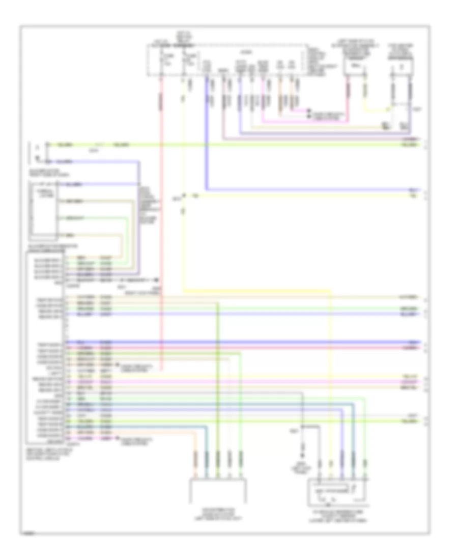
AIR CONDITIONING
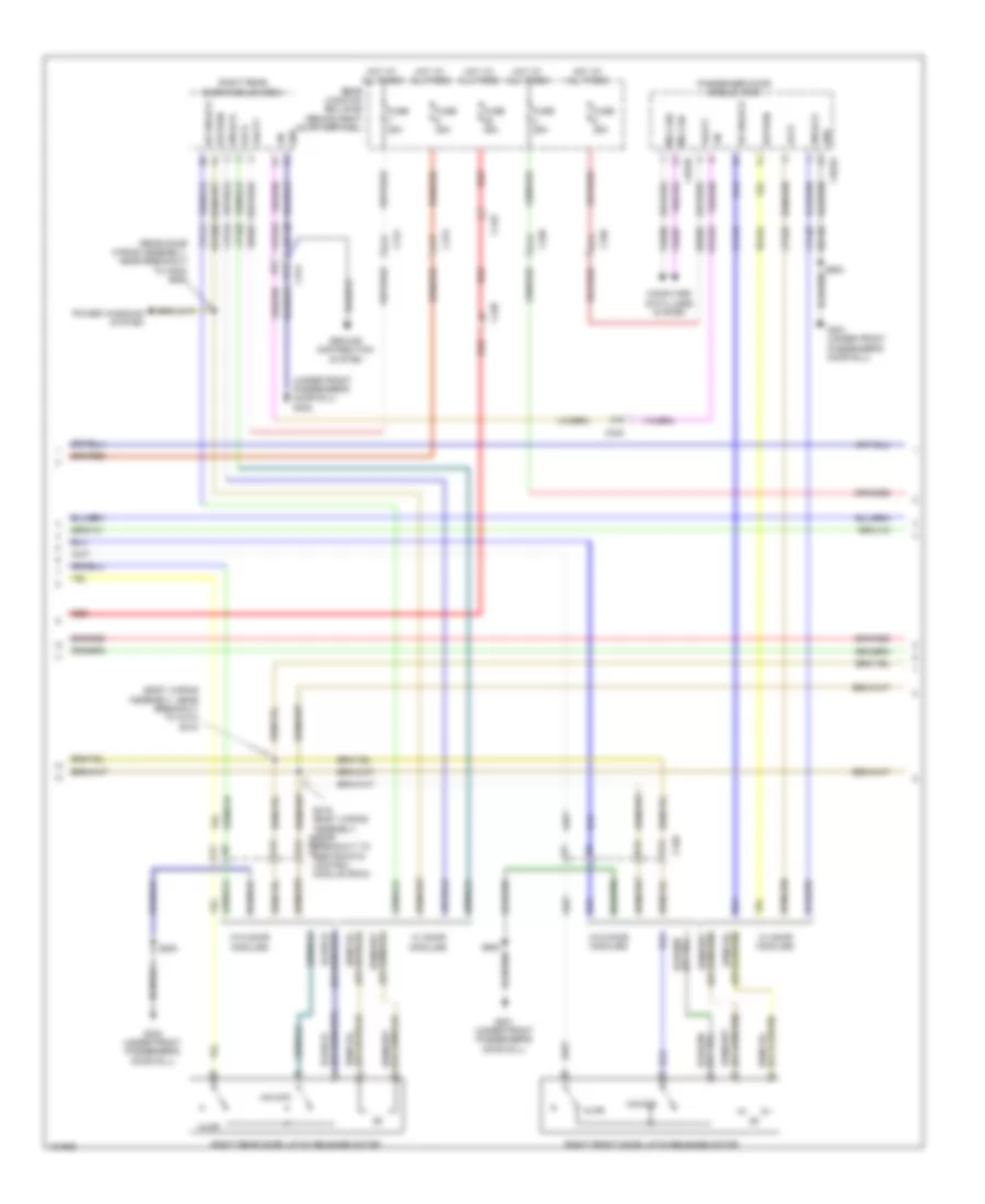
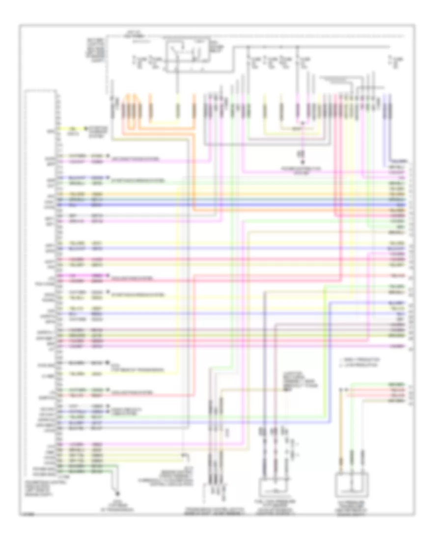
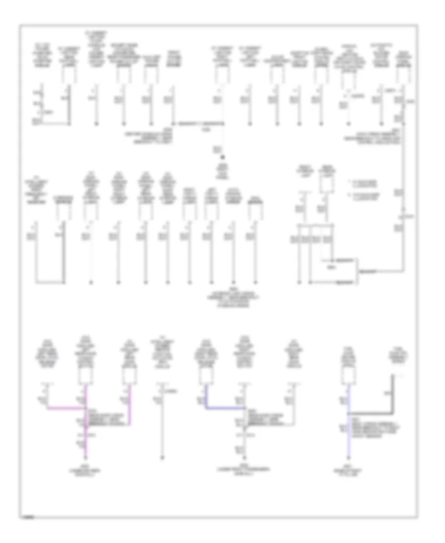
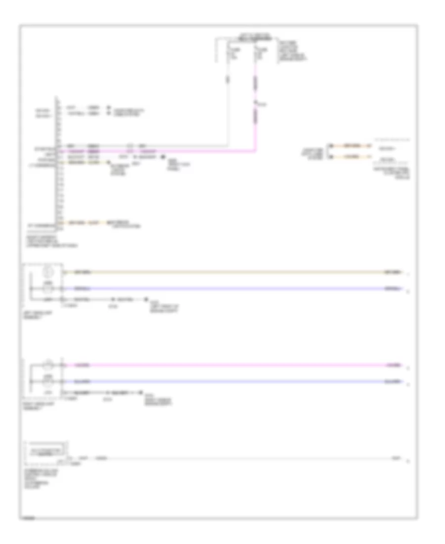
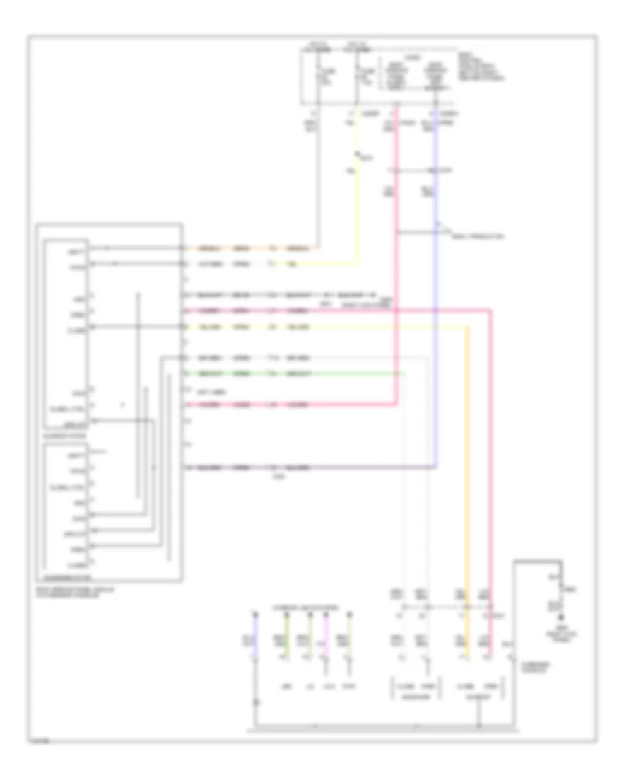
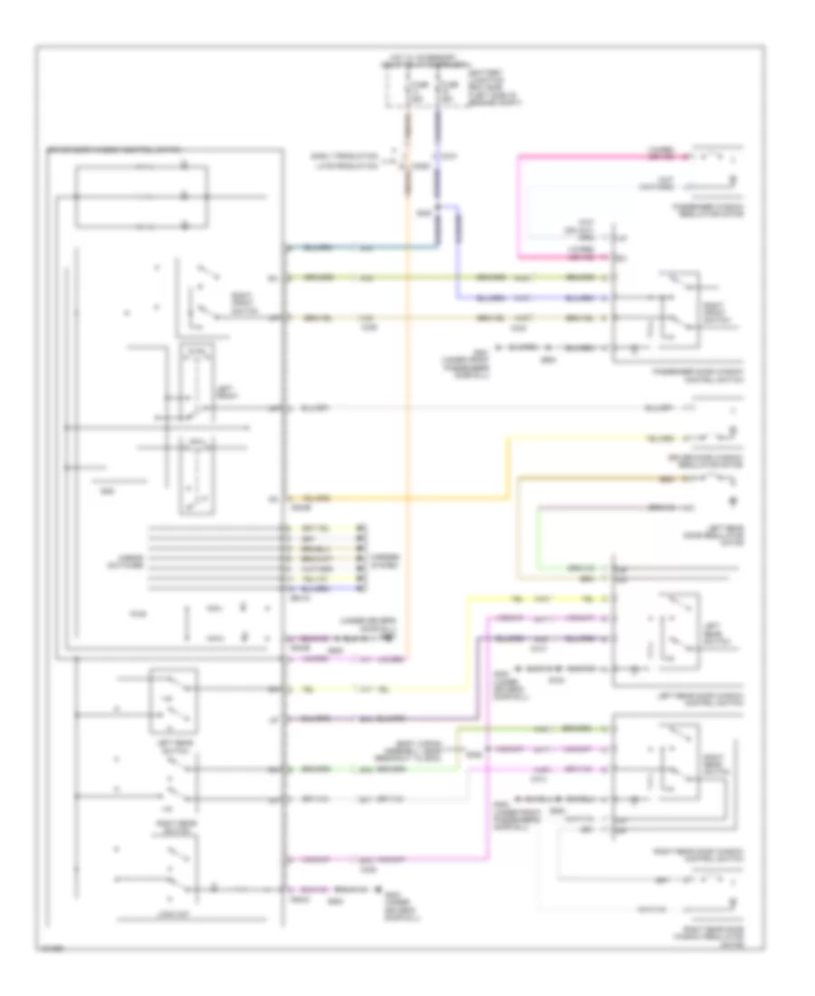
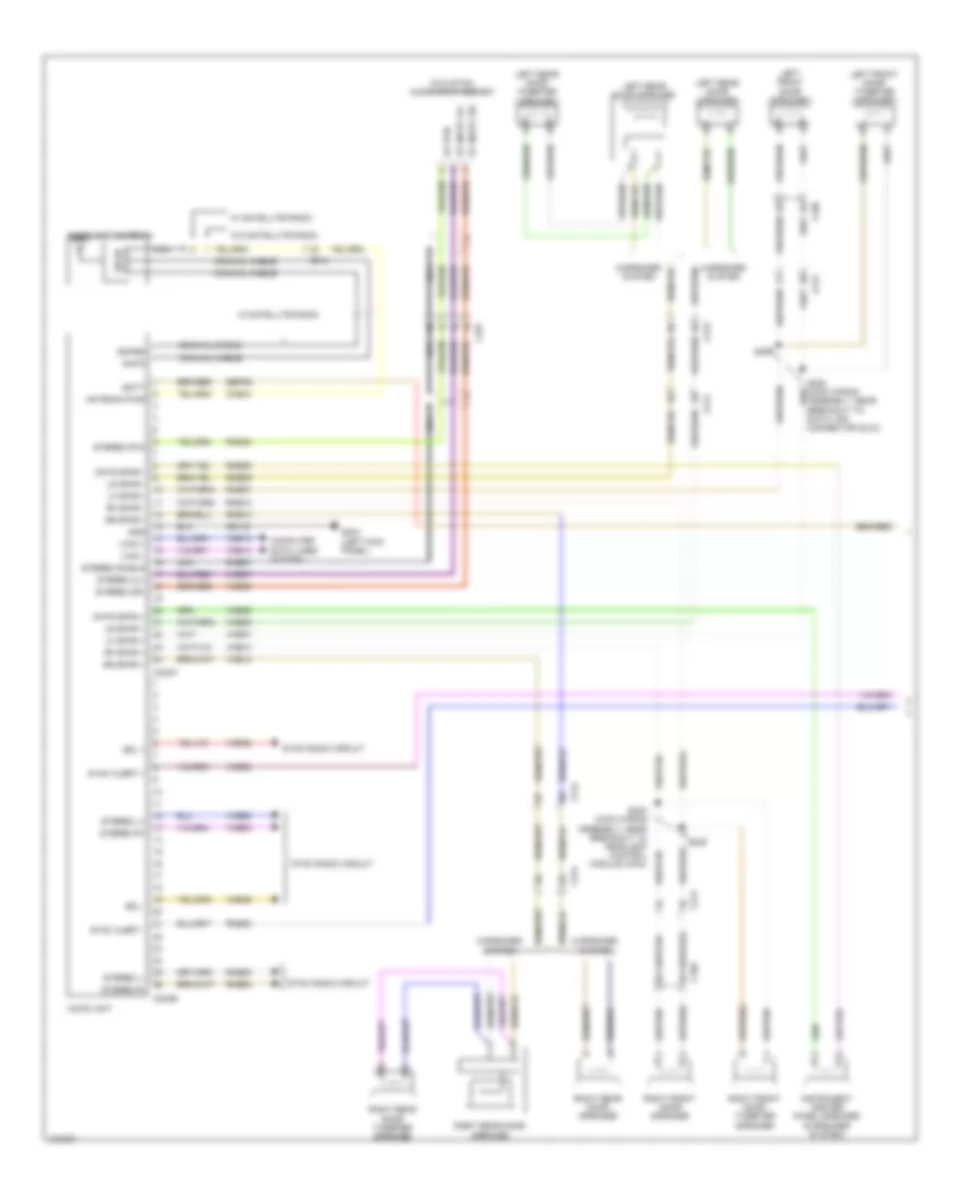
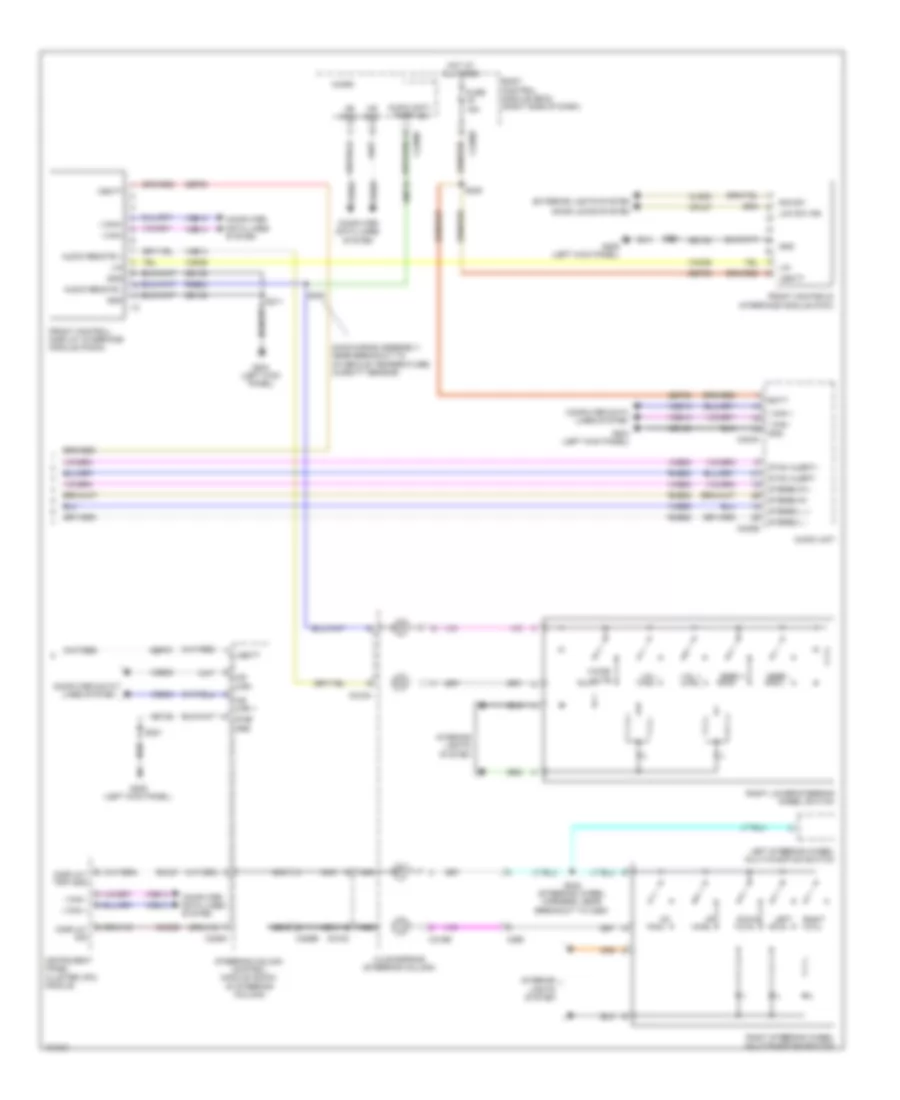
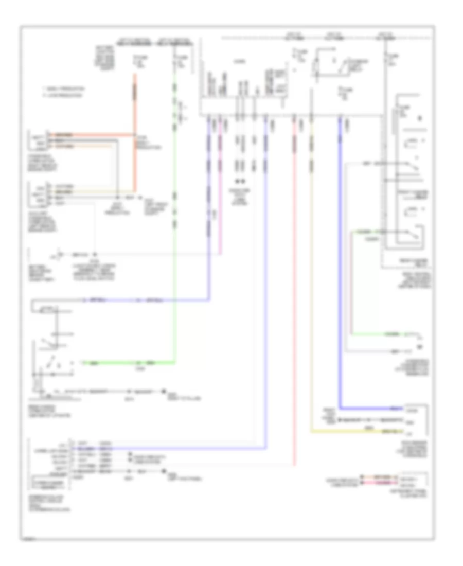
Automatic A/C Wiring Diagram (1 of 3) for Ford Escape S 2014
 https://portal-diagnostov.com/license.html
Automotive Electricians Portal FZCO
Automotive Electricians Portal FZCO
https://portal-diagnostov.com/license.html
https://portal-diagnostov.com/license.html
Automotive Electricians Portal FZCO
Automotive Electricians Portal FZCO
List of elements for Automatic A/C Wiring Diagram (1 of 3) for Ford Escape S 2014:
- (left kick panel) g205
- (left side of hvac evaporator assembly) evaporator temperature sensor
- (main wiring assembly, near breakout to passenger air bag
- (right kick panel) g206
- (steering wheel harness, near breakout to c260) s244
- (top center of dash) autolamp/sunload sensor
- Active grille shutter (1.6l turbo & 2.5l) (behind right end of front grille)
- Aspirator gnd
- Auto lamps snsr
- Blower ctrl
- Blower diode (early production) (battery junction box)
- Blower motor (right side of dash)
- Blower motor control module (on blower motor)
- Bmrc
- Body control module (bcm) (bottom right center of dash)
- C213
- C219
- C2280a
- C2280b
- C2280c
- C2280f
- C228b
- C297a
- C297b
- Ch123
- Ch402
- Computer data lines system
- Deactivation (pad) indicator)
- Disc floor l snsr
- Disc floor r snsr
- Disc panel l snsr
- Disc panel r snsr
- Electronic automatic temperature control (eatc) module
- Evap temp snsr
- Fuse 10a
- Fuse 7.5a
- Gd133
- Gd138
- Gnd
- Hot at all times
- Hot w/ ignition relay energized
- Humidity snsr
- In car snsr +
- In car snsr -
- In-vehicle temperature/ humidity sensor (lower left center of dash)
- L sunl snsr
- Left floor discharge air temperature sensor
- Left panel discharge air temperature sensor
- Lin
- Micro
- Motor+
- Motor-
- Ms can +
- Ms can -
- Ms can+
- Ms can-
- Nca
- Ptc htr ctrl
- R sunl snsr
- Rh103
- Rh104
- Rh105
- Right floor discharge air temperature sensor
- Right panel discharge air temperature sensor
- Rlf14
- S218
- S221
- S241
- S249
- Sbp71
- Sig rtn
- Snsr
- Snsr gnd
- Vbatt
- Vdb06
- Vdb07
- Vh101
- Vh406
- Vh409
- Vh410
- Vh411
- Vh412
- Vh413
- Vh414
- Vh416
- Vh417
- Vlf14
- Vpwr
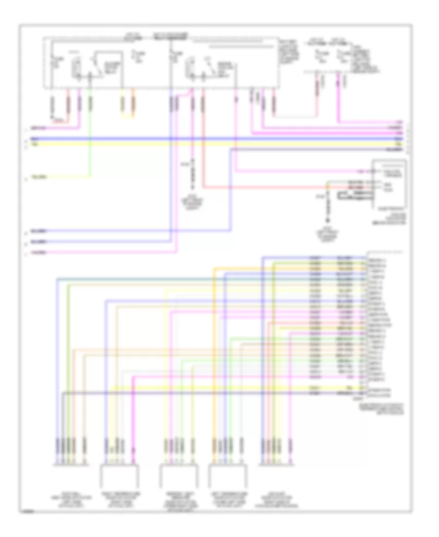
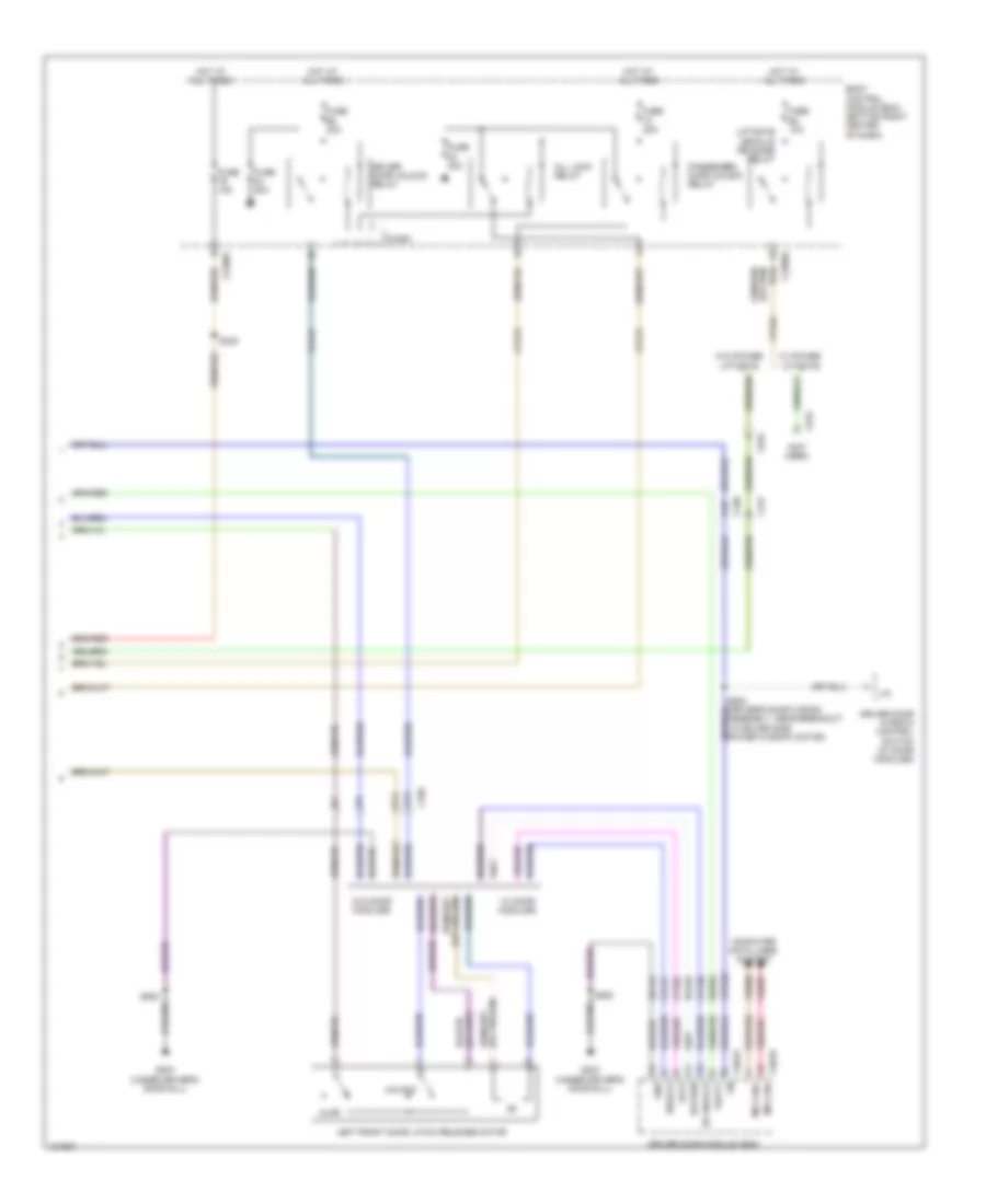
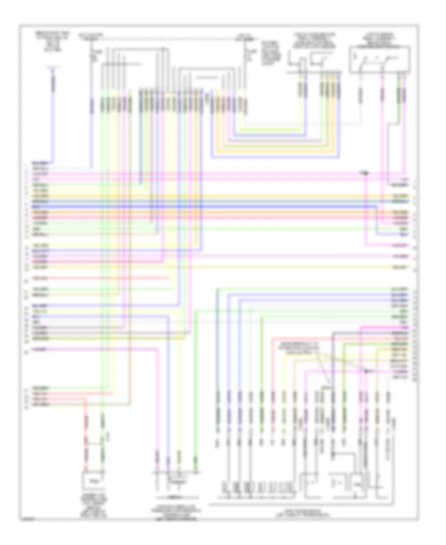
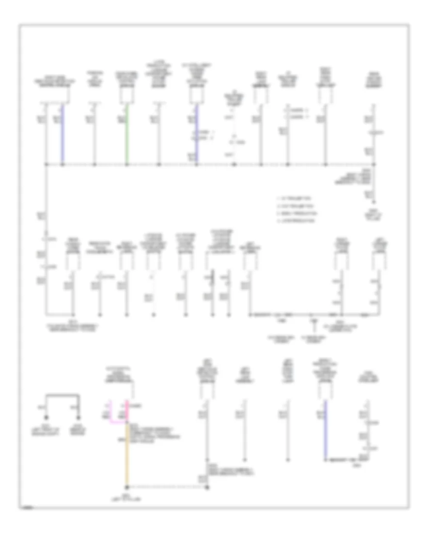
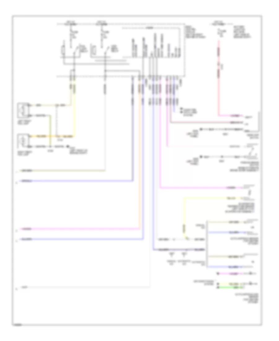
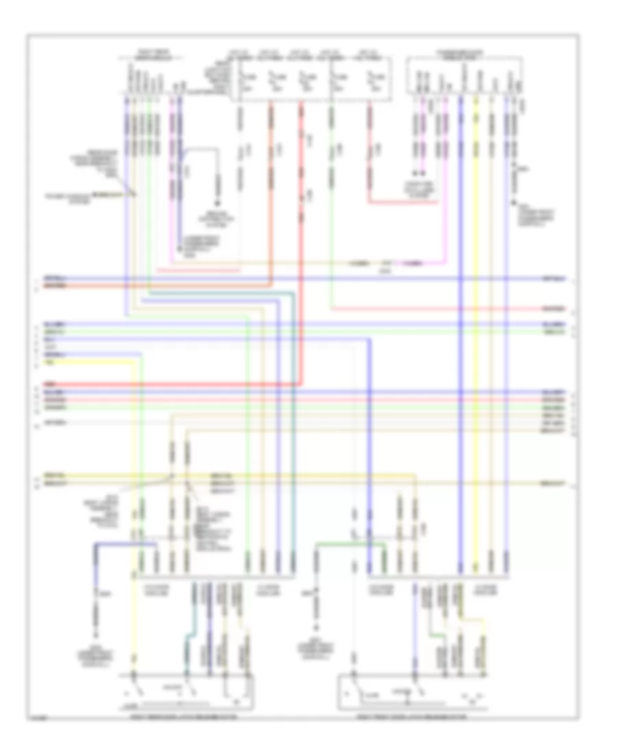
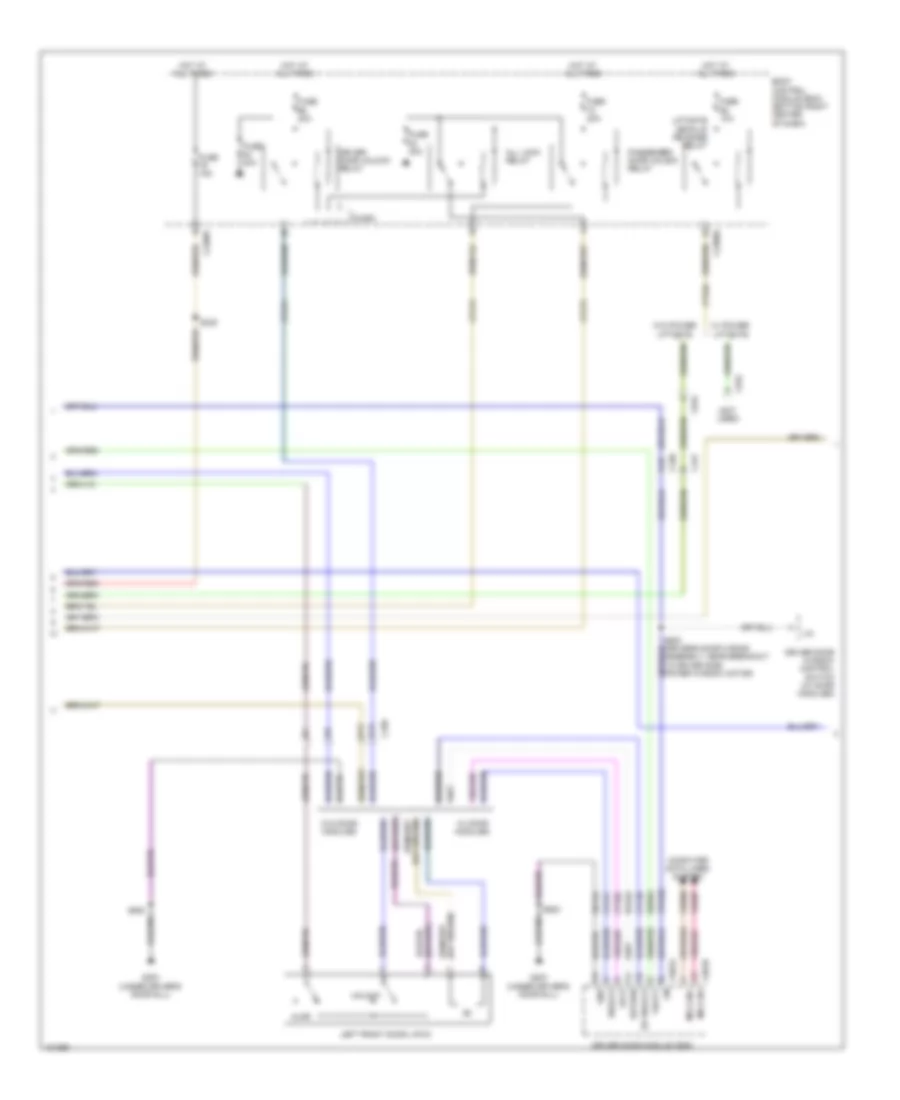
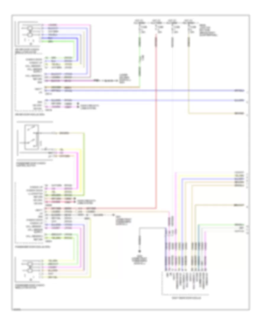
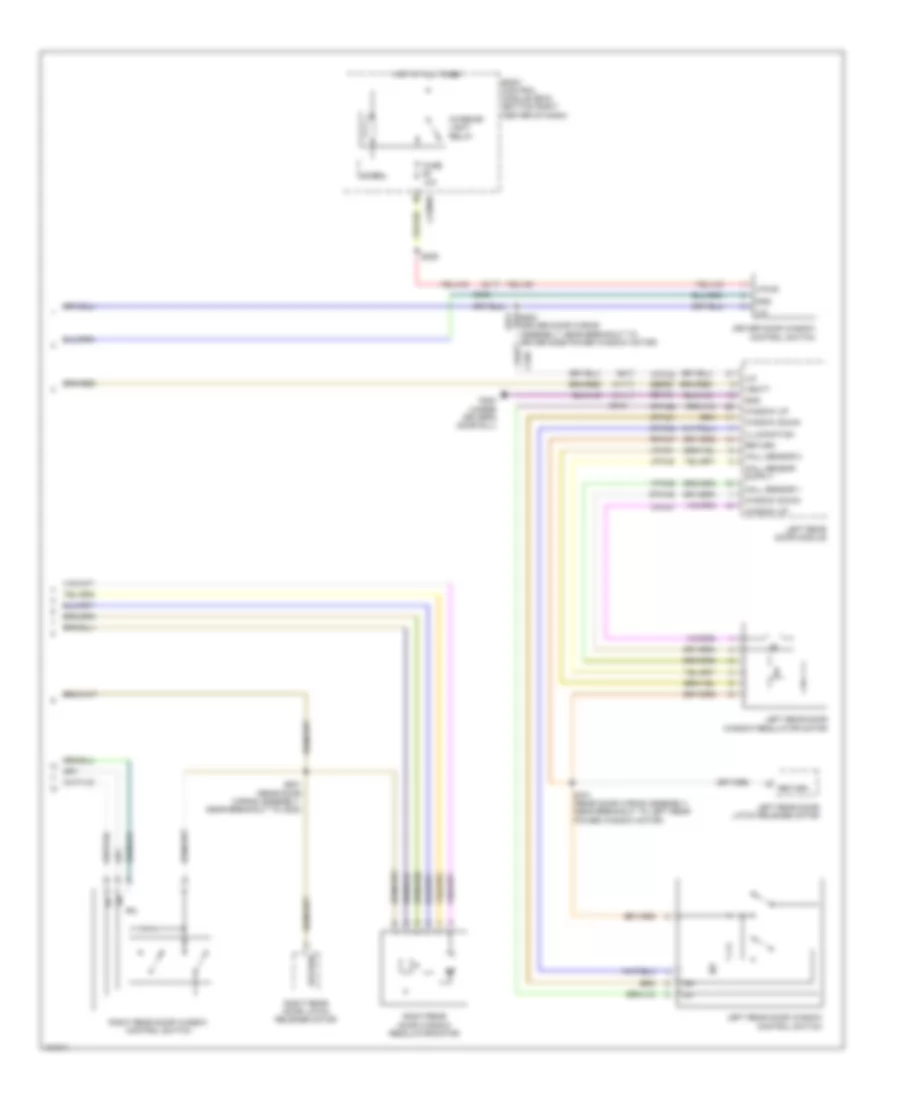
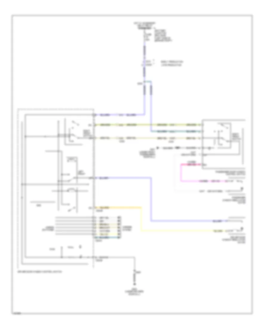
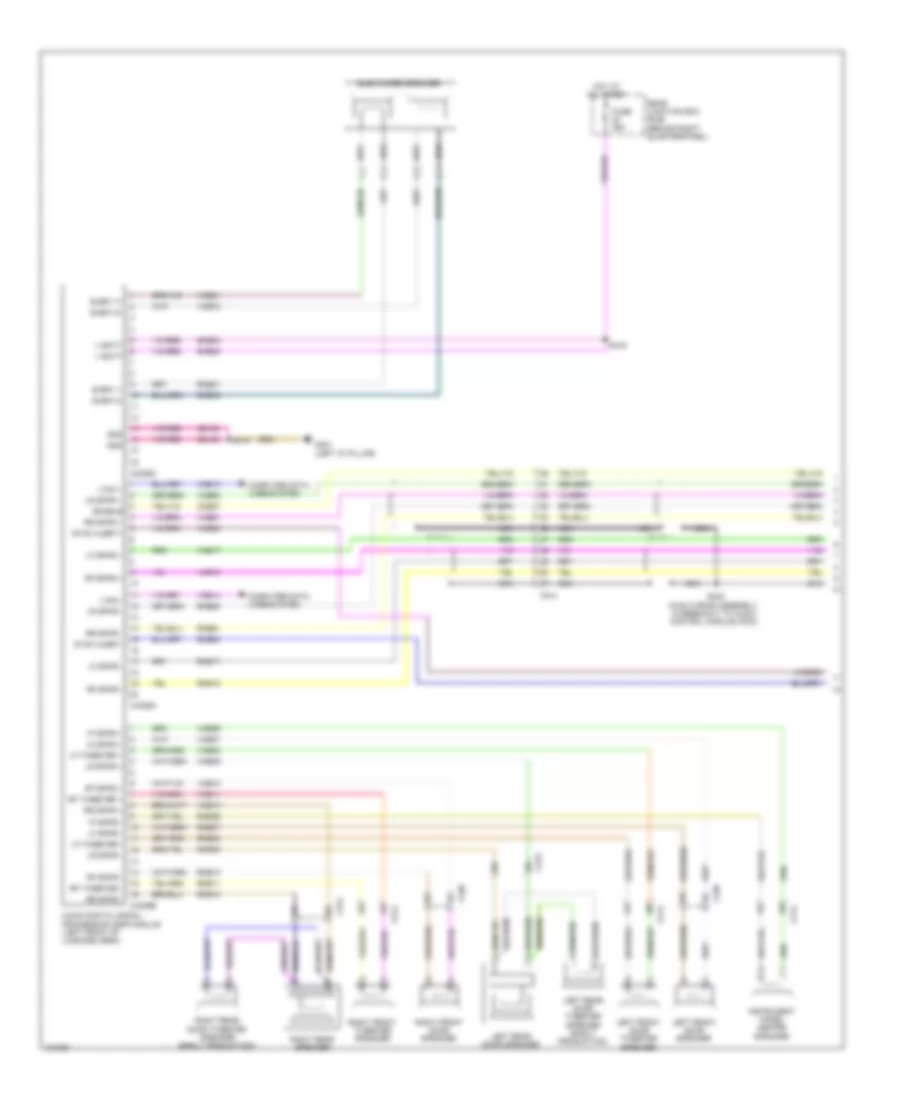
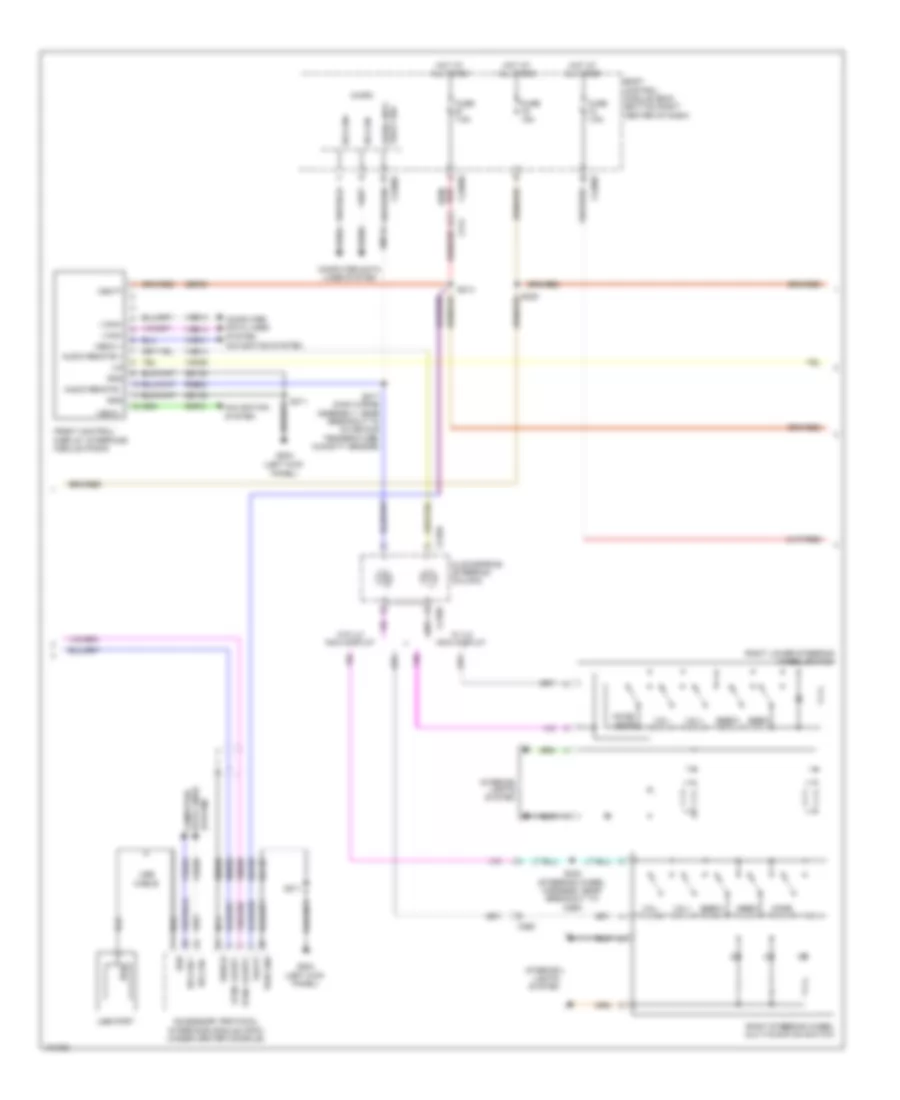
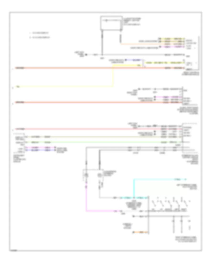
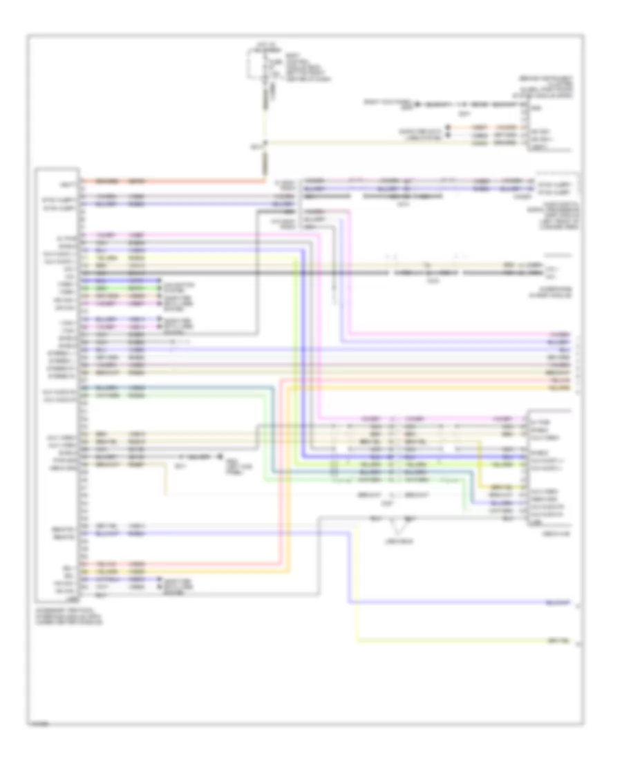
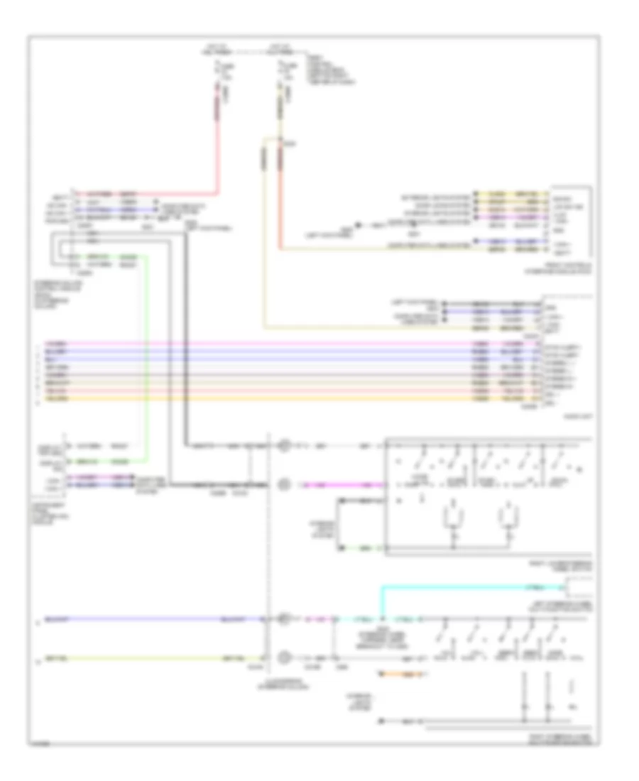
Automatic A/C Wiring Diagram (2 of 3) for Ford Escape S 2014
List of elements for Automatic A/C Wiring Diagram (2 of 3) for Ford Escape S 2014:
- Air inlet door actuator (right side of hvac blower housing)
- Battery junction box (bjb) (left side of engine compt)
- Blower motor relay
- C1035c
- C1617e
- C1617h
- C228a
- Ch201
- Ch202
- Ch203
- Ch204
- Ch205
- Ch206
- Ch207
- Ch208
- Ch209
- Ch210
- Ch211
- Ch212
- Ch213
- Ch214
- Ch215
- Ch227
- Ch228
- Ch229
- Ch230
- Ch231
- Ch237
- Ch238
- Ch239
- Ch240
- Ch241
- Cooling fan motor (behind radiator)
- Defr a
- Defr b
- Defr c
- Defr d
- Defr pwr
- Defrost vent/ register door actuator (upper right side of hvac unit)
- Electronic automatic temperature control (eatc) module
- Electronics
- Engine cooling fan relay
- Fan ctrl variable
- Footwell vent door actuator (left side of hvac unit)
- Fuse 40a
- Fuse 50a
- Fuse 5a
- Fuse 80a
- G107 (left front of engine compt)
- Gnd
- High current battery junction box (bjb) (left side of engine compt)
- Hot at all times
- Hot w/ pcm power relay energized
- Left temperature door actuator (lower left side of hvac unit)
- Ltemp a
- Ltemp b
- Ltemp c
- Ltemp d
- Ltemp pwr
- Nca
- Pa/fl a
- Pa/fl b
- Pa/fl c
- Pa/fl d
- Pa/fla pwr
- Pwr
- Recirc a
- Recirc b
- Recirc c
- Recirc d
- Recirc pwr
- Right temperature door actuator (right side of hvac unit)
- Rtemp a
- Rtemp b
- Rtemp c
- Rtemp d
- Rtemp pwr
- S144
- S148
- S149
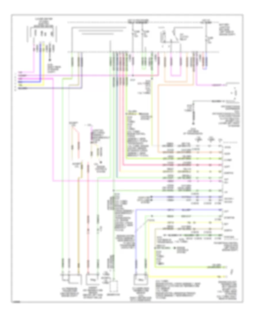
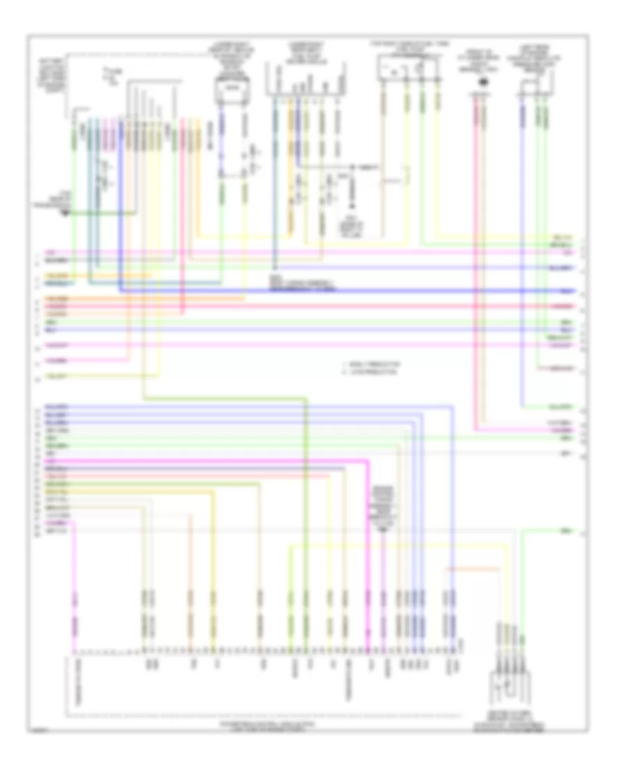
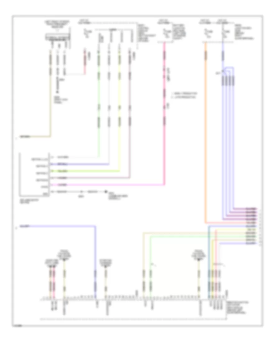
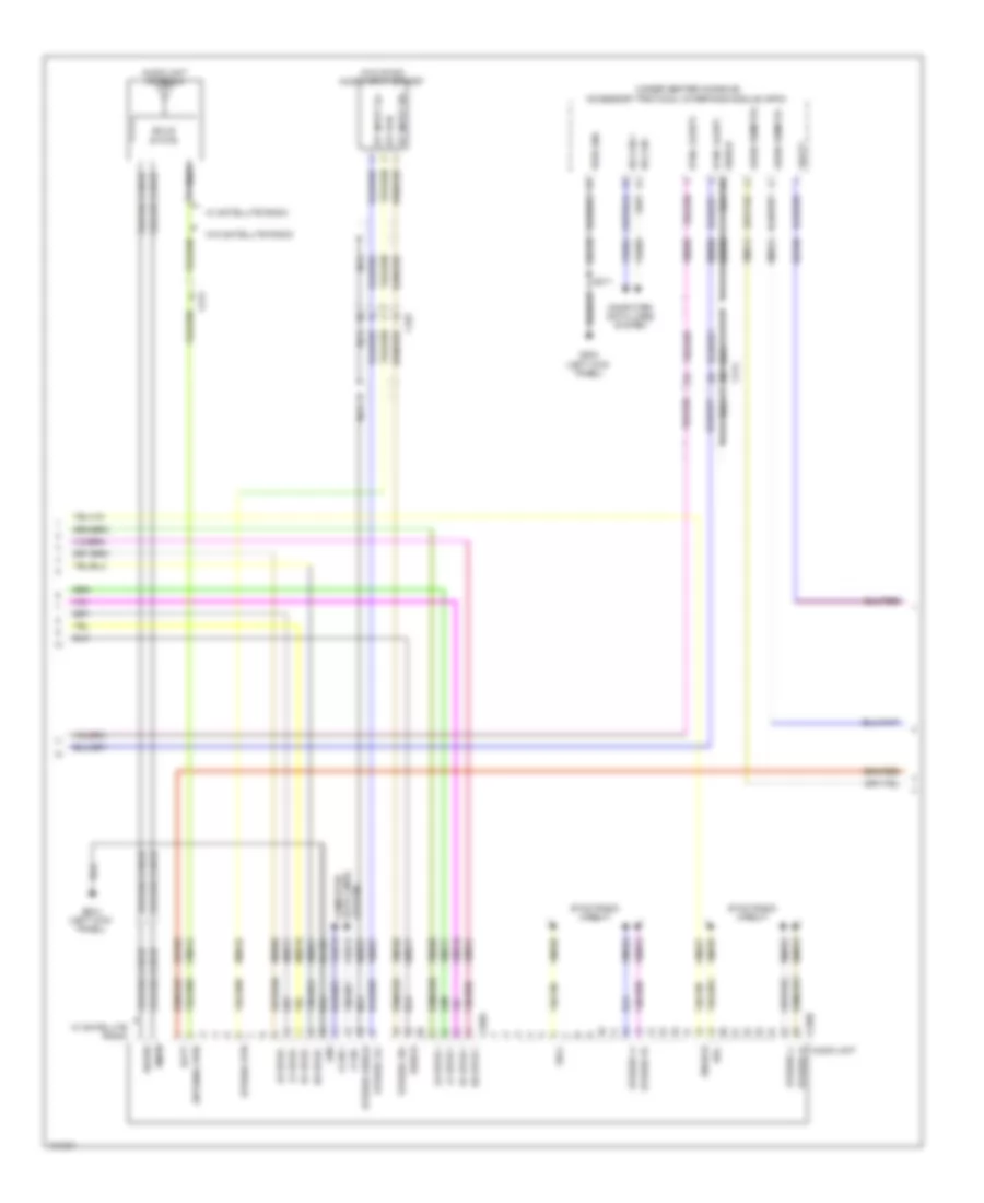
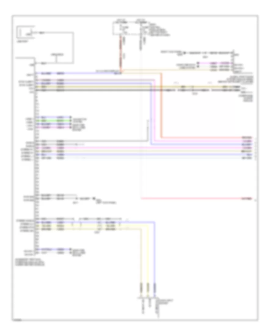
Automatic A/C Wiring Diagram (3 of 3) for Ford Escape S 2014
List of elements for Automatic A/C Wiring Diagram (3 of 3) for Ford Escape S 2014:
- (2.0l turbo: engine control wiring assembly, near breakout to intake air temperature (iat) sensor) (1.6l turbo: engine control sensor extension wiring assembly, near breakout to c1026)
- (engine control wiring assembly, near breakout to ignition transformer capacitor 1)
- (lower center of dash) electric booster heater
- 1.6l turbo
- 2.0l turbo
- 2.5l
- A/c clutch relay
- A/c pressure transducer (center rear of engine compt)
- Aat
- Accr
- Acpt
- Air conditioning compressor (2.5l) air conditioning clutch & air conditioning clutch field coil (except 2.5l) (lower left front of engine)
- Ambient air temperature sensor (behind left side of front grille)
- Battery junction box (bjb) (left side of engine compt)
- C-vref
- C1035c
- C134
- C1381b
- C1381e
- C1551b
- C1551e
- C175b
- C175e
- C2603a
- C2603b
- C2603c
- Cbb08 (or cbb32)
- Ch109 (or ch302)
- Cht
- Computer data lines system
- Cylinder head temperature sensor (2.5l) (right center side of cylinder bank)
- Ect
- Engine controls system
- Engine coolant temperature (ect) sensor (except 2.5l) (1.6l turbo: rear of engine) (2.0l turbo: right rear of engine)
- Except 1.6l turbo
- Except 2.5l
- Fcv
- Fuse 10a
- Fuse 15a
- G104 (top rear of transmission)
- G106 (right rear of engine compt)
- Gd120
- Generator
- Gnd
- Hot at all times
- Hot w/ pcm power relay energized
- Hs can +
- Hs can -
- Ign
- Le424 (or lh108)
- Lin
- Near breakout to 6f35 transmission) (2.5l: engine control wiring assembly, near breakout to c145)
- Powertrain control module (pcm) (left side of engine compt)
- Pwm
- Pwr gnd
- Re405
- Re407 (or rh107)
- Re454 (or re329)
- S103 (2.0l turbo) s112 (2.5l) s13 (1.6l turbo)
- S105 (2.0l turbo) s129 (1.6l turbo) (2.0l turbo: engine control wiring assembly, near breakout to 6f35 transmission) (1.6l turbo: engine control sensor extension wiring assembly, near breakout to g104)
- S108 (2.0l turbo) s123 (1.6l turbo)
- S125 (1.6l turbo)
- S147
- S176
- Sigrtn
- Sigrtnc
- Stgrtne
- Vdb04
- Vdb05
- Vdn06 (or vdc46) (or vdn08)
- Ve203
- Ve712
- Ve716
- Ve750 (or vh407)
- Vh443 (or vh442)
- Vpwr
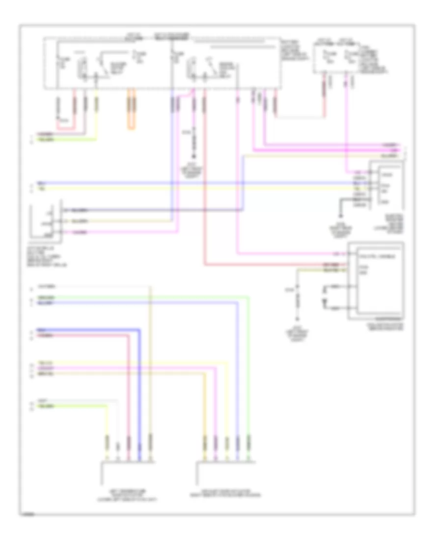
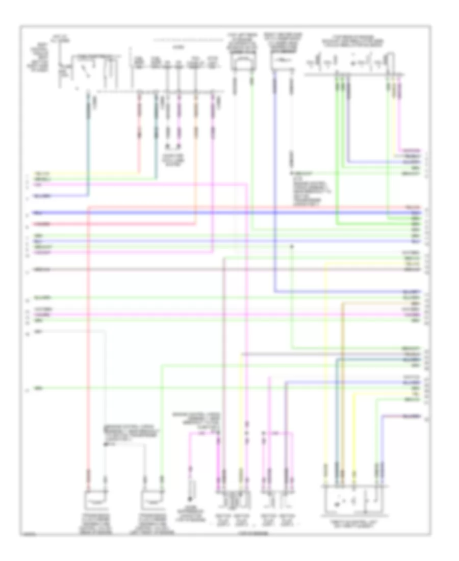
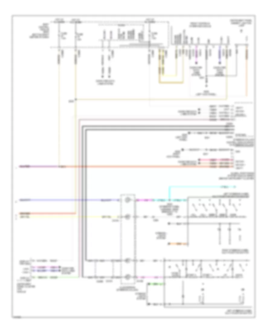
Manual A/C Wiring Diagram (1 of 3) for Ford Escape S 2014
List of elements for Manual A/C Wiring Diagram (1 of 3) for Ford Escape S 2014:
- (left side of hvac evaporator assembly) evaporator temperature sensor
- (top center of dash) autolamp & rain sensor
- Air distribution door actuator (left side of hvac unit)
- Auto lamps snsr
- Blower motor (right side of dash)
- Blower motor resistor (on blower motor)
- Blower spd 1
- Blower spd 2
- Blower spd 3
- Blower spd 4
- Bmrc
- Body control module (bcm) (bottom right center of dash)
- C219
- C2280a
- C2280b
- C2280c
- C2280f
- C2357a
- C2357b
- C237
- Ch123
- Ch201
- Ch202
- Ch203
- Ch204
- Ch205
- Ch206
- Ch207
- Ch208
- Ch209
- Ch210
- Ch232
- Ch233
- Ch234
- Ch235
- Ch236
- Ch403
- Ch427
- Ch428
- Ch429
- Chp01
- Computer data lines system
- Evap temp snsr
- Fuse 10a
- Fuse 7.5a
- G205 (left kick panel)
- G206 (right kick panel)
- Gd133
- Gd138
- Gnd
- Heating, ventilation & air conditioing (hvac) control module
- Hot at all times
- Hot w/ ignition relay energized
- Humidity snsr
- In car snsr +
- In car snsr -
- In-vehicle temperature/ humidity sensor (lower left center of dash)
- Micro
- Mode door a
- Mode door b
- Mode door c
- Mode door d
- Mode dr pwr
- Ms can +
- Ms can -
- Ms can+
- Ms can-
- Ptc htr ctrl
- Recirc dr a
- Recirc dr b
- Recirc dr c
- Recirc dr d
- Recirc dr pwr
- Rh105
- Rlf14
- S216 (main wiring assembly, near breakout to blower motor)
- S218
- S221
- S241
- Sbp71
- Sig rtn
- Snsr
- Temp door a
- Temp door b
- Temp door c
- Temp door d
- Temp dr pwr
- Thermal limiter
- V batt
- Vdb06
- Vdb07
- Vh406
- Vh413
- Vh414
- Vlf14
- Vpwr
Manual A/C Wiring Diagram (2 of 3) for Ford Escape S 2014
List of elements for Manual A/C Wiring Diagram (2 of 3) for Ford Escape S 2014:
- Active grille shutter (2.5l & 1.6l turbo) (behind right end of front grille)
- Air inlet door actuator (right side of hvac blower housing)
- Battery junction box (bjb) (left side of engine compt)
- Blower motor relay
- C1035c
- C1617e
- C1617h
- C2603a
- C2603b
- C2603c
- Cooling fan motor (behind radiator)
- Electric booster heater (lower center of dash)
- Electronics
- Engine cooling fan relay
- Fan ctrl variable
- Fuse 40a
- Fuse 50a
- Fuse 5a
- Fuse 80a
- G106 (right rear of engine compt)
- G107 (left front of engine compt)
- Gnd
- High current battery junction box (bjb) (left side of engine compt)
- Hot at all times
- Hot w/ pcm power relay energized
- Ign
- Left temperature door actuator (lower left side of hvac unit)
- Lin
- Nca
- Pwm
- Pwr
- S144
- S148
- S149
- Vpwr
Manual A/C Wiring Diagram (3 of 3) for Ford Escape S 2014
List of elements for Manual A/C Wiring Diagram (3 of 3) for Ford Escape S 2014:
- (2.0l turbo: engine control wiring assembly, near breakout to intake air temperature (iat) sensor) (1.6l turbo: engine control sensor extension wiring assembly, near breakout to c1026)
- (engine control wiring assembly, near breakout to ignition transformer capacitor 1)
- (junction box wiring assembly, near breakout to bjb) s146
- (top rear of transmission) g104
- 1.6l turbo
- 2.0l turbo
- 2.5l
- A/c clutch relay
- A/c pressure transducer (center rear of engine compt)
- Aat
- Accr
- Acpt
- Air conditioning compressor (2.5l) air conditioning clutch & air conditioning clutch field coil (except 2.5l) (lower left front of engine)
- Ambient air temperature sensor (behind left side of front grille)
- Battery junction box (bjb) (left side of engine compt)
- C-vref
- C1035c
- C134
- C1381b
- C1381e
- C1551b
- C1551e
- C175b
- C175e
- Cbb08 (or cbb32)
- Ch109 (or ch302)
- Cht
- Computer data lines system
- Cylinder head temperature sensor (2.5l) (right center side of cylinder bank)
- Ect
- Engine controls system
- Engine coolant temperature (ect) sensor (except 2.5l) (1.6l turbo: rear of engine) (2.0l turbo: right rear of engine)
- Except 1.6l turbo
- Except 2.5l
- Fcv
- Fuse 10a
- Fuse 15a
- G104 (top rear of transmission)
- Gd120
- Generator
- Hot at all times
- Hot w/ pcm power relay energized
- Hs can +
- Hs can -
- Le424 (or lh108)
- Lin
- Powertrain control module (pcm) (left side of engine compt)
- Pwr gnd
- Re405
- Re407 (or rh107)
- Re454 (or re329)
- S103 (2.0l turbo) s112 (2.5l) s13 (1.6l turbo)
- S105 (2.0l turbo) s129 (1.6l turbo) (2.0l turbo: engine control wiring assembly, near breakout to 6f35 transmission) (1.6l turbo: engine control sensor extension wiring assembly, near breakout to g104)
- S108 (2.0l turbo) s123 (1.6l turbo)
- S115 (2.5l) s107 (2.0l turbo) (2.0l turbo: engine control wiring assembly, near breakout to 6f35 transmission) (2.5l: engine control wiring assembly, near breakout to c145)
- S125 (1.6l turbo)
- S147
- S176
- Sigrtn
- Sigrtnc
- Sigrtne
- Vdb04
- Vdb05
- Vdn06 (or vdc46) (or vdn08)
- Ve203
- Ve712
- Ve716
- Ve750 (or vh407)
- Vh443 (or vh442)
- Vpwr
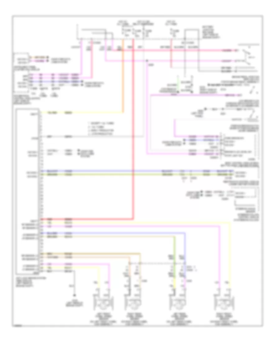
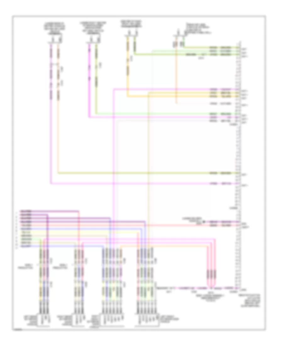
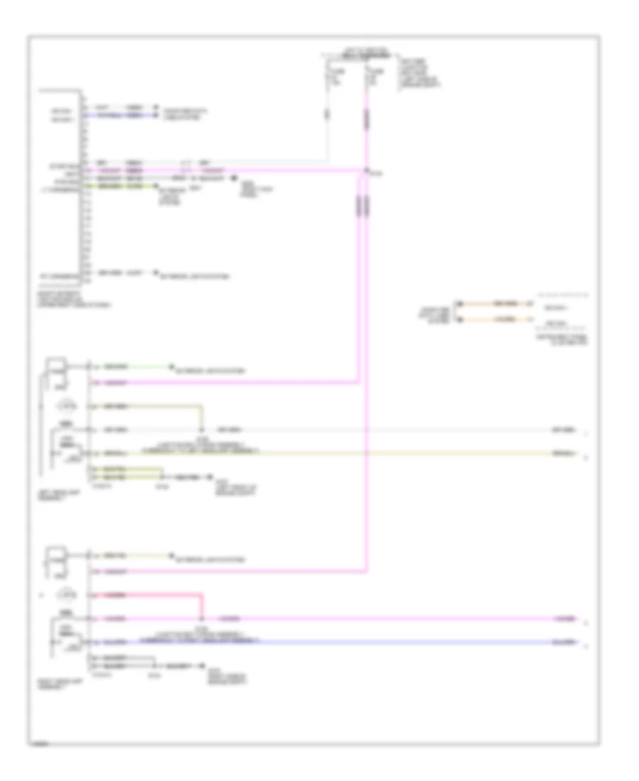
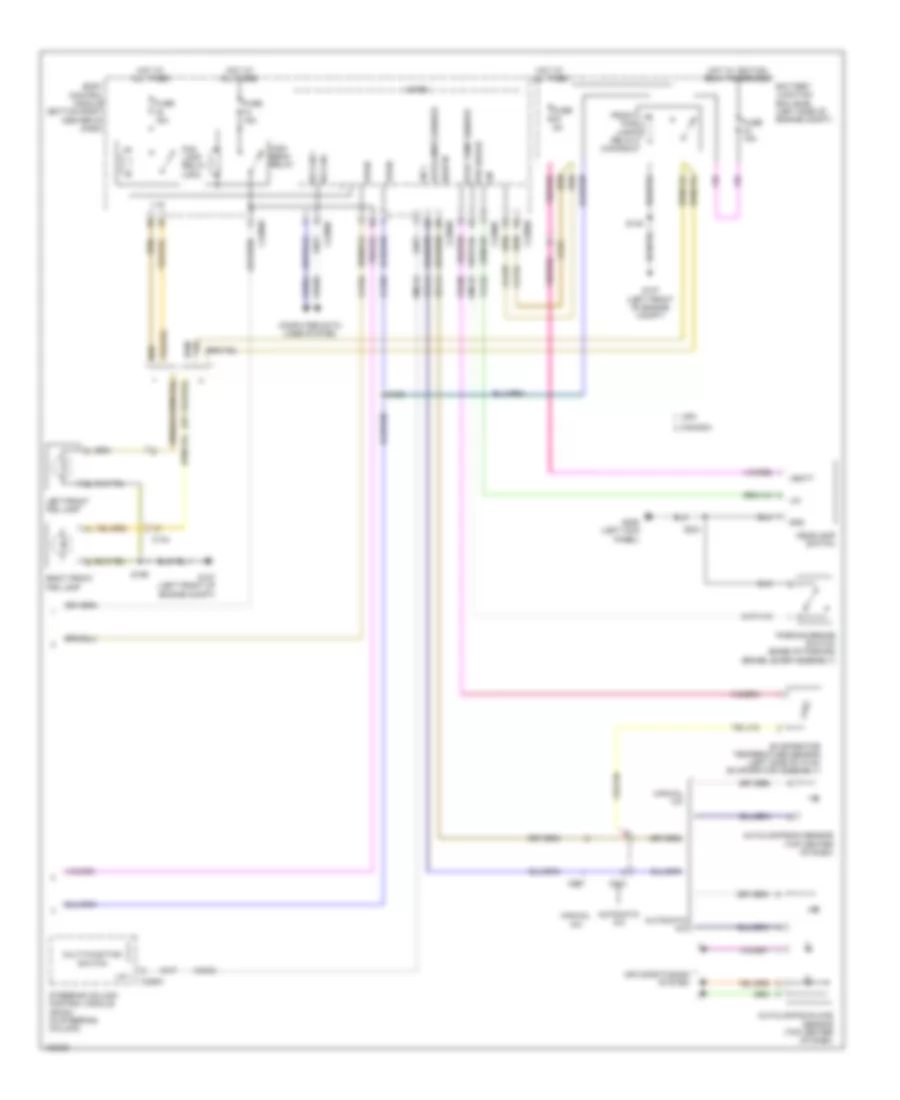
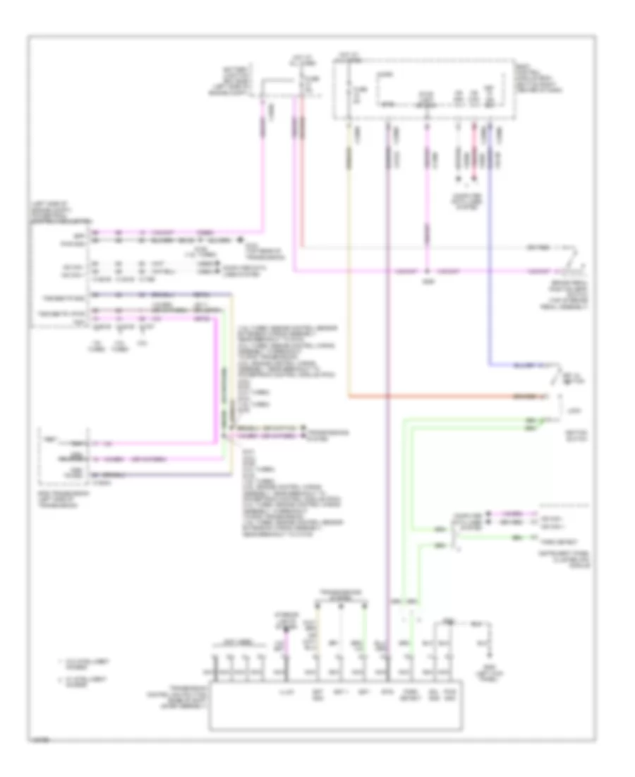
ANTI-LOCK BRAKES
Anti-lock Brakes Wiring Diagram for Ford Escape S 2014
List of elements for Anti-lock Brakes Wiring Diagram for Ford Escape S 2014:
- (top rear of transmission) g104
- 1.6l turbo
- 2.0l turbo
- 2.5l
- Anti-lock brake system (abs) module (left rear of engine compt)
- Battery junction box (bjb) (left side of engine compt)
- Body control module (bcm) (bottom right center of dash)
- Bpp
- Bps
- Brake fluid level sw
- Brake pedal position (bpp) switch (top of brake pedal assembly)
- C1035c
- C1381b
- C1551b
- C175b
- C210
- C226a
- C2280a
- C2280c
- C3053
- C310b
- C405
- C406
- Cbp03
- Ccb08
- Ces09
- Cmc19
- Cmc25
- Computer data lines system
- Early production
- Except 1.6l turbo
- Fuse 30a
- Fuse 40a
- Fuse 5a
- G103 (right side of engine compt)
- G105 (left rear of engine compt)
- G205 (left kick panel)
- Gd122
- Gnd
- Hot at all times
- Hot w/ ign relay energized
- Hs can +
- Hs can -
- Hs can2 +
- Hs can2 -
- Instrument panel cluster (ipc) module
- Late production
- Left front wheel speed sensor (on left front wheel hub assembly)
- Left rear wheel speed sensor (on left rear wheel hub assembly)
- Lf sensor hi
- Lf sensor lo
- Low brake fluid warning indicator switch (on brake fluid reservoir)
- Lr sensor hi
- Lr sensor lo
- Micro
- Ms can +
- Ms can -
- Nca
- Park brake sw
- Parking brake switch (base of parking brake lever assembly)
- Powertrain control module (pcm) (left side of engine compt)
- Rca17
- Rca18
- Rca19
- Rca20
- Red
- Restraints control module (under center console)
- Rf sensor hi
- Rf sensor lo
- Right front wheel speed sensor (on right front wheel hub assembly)
- Right rear wheel speed sensor (on right rear wheel hub assembly)
- Rr sensor hi
- Rr sensor lo
- S125
- S134
- S221
- S250
- Sbb25
- Sbb26
- Steering angle sensor
- Steering column control module (in steering column)
- Stop light sw
- Vbatt
- Vca03
- Vca04
- Vca05
- Vca06
- Vca23
- Vca24
- Vdb04
- Vdb05
- Vpwr
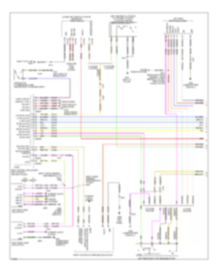
ANTI-THEFT
Forced Entry Wiring Diagram, with Intelligent Access (1 of 5) for Ford Escape S 2014
List of elements for Forced Entry Wiring Diagram, with Intelligent Access (1 of 5) for Ford Escape S 2014:
- (body wiring assembly, near breakout to c211) s200
- (body wiring assembly, near breakout to g201) s204
- (left center of liftgate) (w/o power liftgate) liftgate/luggage compartment lid latch
- (lower left side of liftgate) rear gate trunk module
- (right "d" pillar) g400
- A11
- A12
- A13
- Ajar
- Body control module (bcm) (bottom right center of dash)
- C214
- C2280a
- C2280b
- C2280c
- C2280h
- C313
- C339
- C340
- C4174a
- C4174b
- C431
- C934
- Ccd15
- Cls32
- Computer data lines system
- Cpl04
- Cpl25
- Cpl26
- Cpl30
- Cpl31
- Cpl35
- Cpl36
- Cpl38
- Cpl39
- Cpl41
- Cpl42
- Cpl43
- Cpl44
- Cpl53
- Cpl81
- Cpl87
- Crh04
- Dr lock cntrl sw ind (led)
- Dr unlock
- Front controls interface module (fcim)
- G103 (right side of engine compt)
- G107 (left front of engine compt)
- G201 (under front passenger's door sill)
- G203 (under driver's door sill)
- G205 (left kick panel)
- G300 (under driver's door sill)
- G400 (right "d" pillar)
- Gd123
- Gd133
- Gd134
- Gd150
- Gnd
- Hazard warning signal switch/
- Hood ajar sw
- Hood switch (w/ perimeter alarm) (center front of engine compt)
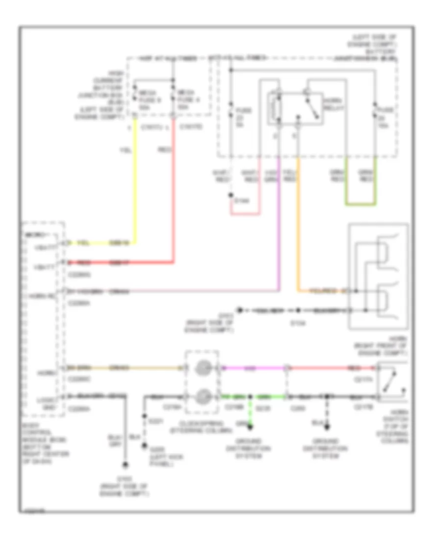
- Horn rly ctrl
- Horns system
- Illum
- Interior lights system
- K-line
- Left front door lock switch
- Left rear door latch release motor
- Left rear door module (rdm)
- Lf dr ajar
- Lf dr unlock
- Liftgate ajar
- Lin
- Lock
- Logic gnd
- Lr dr ajar
- Lr dr unlock
- Mem p1
- Mem p2
- Mem p3
- Memory systems
- Micro
- Ms can+
- Ms can-
- Nca
- Power windows system
- Red
- Return
- Rf dr ajar
- Rf dr unlock
- Right front door lock switch
- Rpw07
- Rr dr ajar
- Rr dr unlock
- S148
- S221
- S414
- S500
- S600
- S700
- S701 (rear door wiring assembly, near breakout to left rear power window motor)
- Sbp06
- Sbr06
- Sbr25
- Sig sw/hazard warning
- Switch indicator (led) door lock control
- Unlock
- Vbatt
- Vdb06
- Vdb07
- Vpl56
- Vpw32
- Vrt22
- W/ door modules
- W/ memory
- W/ power liftgate
- W/o door modules
- W/o memory
- W/o power liftgate
Forced Entry Wiring Diagram, with Intelligent Access (2 of 5) for Ford Escape S 2014
List of elements for Forced Entry Wiring Diagram, with Intelligent Access (2 of 5) for Ford Escape S 2014:
- (rear door wiring assembly, near breakout to c823) s801
- (under front passenger's door sill) g302
- A11
- A12
- A13
- A14
- A16
- A17
- Ajar
- B12
- C313
- C314
- C339
- C340
- C410
- C438
- C652a
- C652b
- Computer data lines system
- Cpl05
- Cpl35
- Cpl41
- Cpl54
- Cpl65
- Cpl66
- Dr unlock
- Fuse 25a
- G201 (under front passenger's door sill)
- G302 (under front passenger's door sill)
- Gd140
- Gnd
- Ground distribution system
- Hot at all times
- Lin
- Lock
- Ms can+
- Ms can-
- Passenger door module (pdm)
- Power windows system
- Rear junction box (rjb) (behind right quarterpanel)
- Red
- Return
- Right front door latch release motor
- Right rear door latch release motor
- Right rear door module
- Rpl64
- Rpw09
- S318 (body wiring assembly, near breakout to c312)
- S319 (body wiring assembly, near breakout to restraints c314 control module (rcm))
- S600
- S800
- Sbr05
- Sbr07
- Unlock
- Vbatt
- Vdb06
- Vdb07
- Vpw33
- W/ door modules
- W/o door modules
Forced Entry Wiring Diagram, with Intelligent Access (3 of 5) for Ford Escape S 2014
List of elements for Forced Entry Wiring Diagram, with Intelligent Access (3 of 5) for Ford Escape S 2014:
- (not used)
- A12
- A16
- Ajar
- All lock relay
- B12
- Body control module (bcm) (bottom right center of dash)
- C2280e
- C2280f
- C339
- C431
- C501a
- C501b
- C934
- Computer data lines system
- Cpl02
- Cpl30
- Cpl51
- Cpl75
- Cpl76
- Cpl84
- Dr unlock
- Driver door module (ddm)
- Driver door unlock relay
- Driver door window control switch (w/ door modules)
- Fuse 10a
- Fuse 15a
- Fuse 20a
- G203 (under driver's door sill)
- Gd134
- Gnd
- Hot at all times
- Left front door latch
- Liftgate decklid release relay
- Lin
- Lock
- Micro
- Ms can+
- Ms can-
- Passenger door unlock relay
- Return
- Rpl63
- S235
- S500
- S502 (driver's door wiring assembly, near breakout to driver side power window motor)
- Sbr04
- Unlock
- Vbatt
- Vdb06
- Vdb07
- Vpw32
- W/ door modules
- W/ power liftgate
- W/o door modules
- W/o power liftgate
Forced Entry Wiring Diagram, with Intelligent Access (4 of 5) for Ford Escape S 2014
List of elements for Forced Entry Wiring Diagram, with Intelligent Access (4 of 5) for Ford Escape S 2014:
- (left front of roof) radio frequency receiver
- B13
- Battery junction box (bjb) (left side of engine compt)
- Body control module (bcm) (bottom right center of dash)
- C210
- C2280b
- C2280h
- C3053
- C339
- C4392d
- C4392e
- Computer data lines system
- Cpk19
- Cpk20
- Cpk23
- Cpk24
- Cpk25
- Cpk26
- Cpk28
- Cpk29
- Cpk30
- Cpk31
- Cpk34
- Cpk52
- Cpl45
- Early production
- Fuse 10a
- Fuse 5a
- G203 (under driver's door sill)
- G206 (right kick panel)
- Gd138
- Gnd
- Hands free
- Hot at all times
- Internal antenna rke receiver
- K-line
- Keyless entry keypad
- Keypad a
- Keypad b
- Keypad c
- Keypad illum
- Late production
- Liftgate sw
- Lock
- Micro
- Ms can+
- Ms can-
- Rear junction box (rjb) (behind right quarterpanel)
- Remote function actuator (rfa) module (behind left quarterpanel)
- S311
- S500
- Sbp21
- Sig
- Starting/ charging system
- Sw1 start/stop
- Trunk, tailgate, fuel doors system
- Unlock
- Vdb06
- Vdb07
- Vpl56
- Vpwr
- Vrt22
Forced Entry Wiring Diagram, with Intelligent Access (5 of 5) for Ford Escape S 2014
List of elements for Forced Entry Wiring Diagram, with Intelligent Access (5 of 5) for Ford Escape S 2014:
- (center of dash) front keyless vehicle antenna
- (under driver's door sill) g300
- (under rear of center console) center keyless vehicle antenna
- (under right center of rear bumper) rear bumper keyless vehicle antenna
- A12
- A13
- Ant +
- Ant -
- C214
- C313
- C314
- C327
- C339
- C340
- C432
- C4392a
- C4392b
- C4392c
- C511
- C611
- C710
- C810
- Early production
- Gd143
- Gnd
- Left front exterior door handle
- Left rear exterior door handle
- Lock
- Nca
- Rear keyless vehicle antenna (center of spare wheelwell)
- Remote function actuator (rfa) module (behind left quarterpanel)
- Right front exterior door handle
- Right rear exterior door handle
- Rpk01
- Rpk02
- Rpk05
- Rpk06
- Rpk07
- Rpk08
- Rpk39
- S315 (body wiring assembly, near breakout to c214)
- Sbr02
- Unlock
- Vbatt
- Vpk01
- Vpk02
- Vpk05
- Vpk06
- Vpk07
- Vpk08
Forced Entry Wiring Diagram, without Intelligent Access (1 of 3) for Ford Escape S 2014
List of elements for Forced Entry Wiring Diagram, without Intelligent Access (1 of 3) for Ford Escape S 2014:
- (body wiring assembly, near breakout to c211) s200
- (body wiring assembly, near breakout to g201) s204
- (left center of liftgate) (w/o power liftgate) liftgate/luggage compartment lid latch
- (lower left side of liftgate) rear gate trunk module
- (right "d" pillar) g400
- A11
- A12
- A13
- Ajar
- Body control module (bcm) (bottom right center of dash)
- C214
- C2280a
- C2280b
- C2280c
- C313
- C339
- C340
- C4174a
- C4174b
- C431
- C934
- Ccd15
- Cls32
- Computer data lines system
- Cpl04
- Cpl25
- Cpl26
- Cpl30
- Cpl31
- Cpl35
- Cpl36
- Cpl38
- Cpl39
- Cpl41
- Cpl42
- Cpl43
- Cpl44
- Cpl53
- Cpl81
- Cpl87
- Crh04
- Dr lock ctrl sw ind (led)
- Dr unlock
- Front controls interface module (fcim)
- G103 (right side of engine compt)
- G107 (left front of engine compt)
- G201 (under front passenger's door sill)
- G203 (under driver's door sill)
- G205 (left kick panel)
- G300 (under driver's door sill)
- G400 (right "d" pillar)
- Gd123
- Gd133
- Gd134
- Gd150
- Gnd
- Hazard warning signal switch/
- Hood ajar sw
- Hood switch (w/ perimeter alarm) (center front of engine compt)
- Horn rly ctrl
- Horns system
- Illum
- Interior lights system
- Left front door lock switch
- Left rear door latch release motor
- Left rear door module (rdm)
- Lf dr ajar
- Lf dr unlock
- Liftgate ajar
- Lin
- Lock
- Logic gnd
- Lr dr ajar
- Lr dr unlock
- Mem p1
- Mem p2
- Mem p3
- Memory systems
- Micro
- Ms can+
- Ms can-
- Nca
- Power windows system
- Red
- Return
- Rf dr ajar
- Rf dr unlock
- Right front door lock switch
- Rpw07
- Rr dr ajar
- Rr dr unlock
- S148
- S221
- S414
- S500
- S600
- S700
- S701 (rear door wiring assembly, near breakout to left rear power window motor)
- Sbp06
- Sbr06
- Sbr25
- Sig sw/hazard warning
- Switch indicator (led) door lock control
- Unlock
- Vbatt
- Vdb06
- Vdb07
- Vpw32
- W/ door modules
- W/ memory
- W/ power liftgate
- W/o door modules
- W/o memory
- W/o power liftgate
Forced Entry Wiring Diagram, without Intelligent Access (2 of 3) for Ford Escape S 2014
List of elements for Forced Entry Wiring Diagram, without Intelligent Access (2 of 3) for Ford Escape S 2014:
- (body wiring assembly, near breakout to c312) s318
- (rear door wiring assembly, near breakout to c823) s801
- (under front passenger's door sill) g302
- A11
- A12
- A13
- A14
- A16
- A17
- Ajar
- B12
- C313
- C314
- C339
- C340
- C410
- C438
- C652a
- C652b
- Computer data lines system
- Cpl05
- Cpl35
- Cpl41
- Cpl54
- Cpl65
- Cpl66
- Dr unlock
- Fuse 25a
- G201 (under front passenger's door sill)
- G302 (under front passenger's door sill)
- Gd140
- Gnd
- Ground distribution system
- Hot at all times
- Lin
- Lock
- Ms can+
- Ms can-
- Passenger door module (pdm)
- Power windows system
- Rear junction box (rjb) (behind right quarterpanel)
- Red
- Return
- Right front door latch release motor
- Right rear door latch release motor
- Right rear door module (rdm)
- Rpl64
- Rpw09
- S319 (body wiring assembly, near breakout to restraints c314 control module (rcm))
- S600
- S800
- Sbr05
- Sbr07
- Unlock
- Vbatt
- Vdb06
- Vdb07
- Vpw33
- W/ door modules
- W/o door modules
Forced Entry Wiring Diagram, without Intelligent Access (3 of 3) for Ford Escape S 2014
List of elements for Forced Entry Wiring Diagram, without Intelligent Access (3 of 3) for Ford Escape S 2014:
- (not used)
- A12
- A16
- Ajar
- All lock relay
- B12
- Body control module (bcm) (bottom right center of dash)
- C2280e
- C2280f
- C339
- C431
- C501a
- C501b
- C934
- Computer data lines system
- Cpl02
- Cpl30
- Cpl51
- Cpl75
- Cpl76
- Cpl84
- Dr unlock
- Driver door module (ddm)
- Driver door unlock relay
- Driver door window control switch (w/ door modules)
- Fuse 10a
- Fuse 15a
- Fuse 20a
- G203 (under driver's door sill)
- Gd134
- Gnd
- Hot at all times
- Left front door latch release motor
- Liftgate decklid release relay
- Lin
- Lock
- Micro
- Ms can+
- Ms can-
- Passenger door unlock relay
- Return
- Rpl63
- S235
- S500
- S502 (driver's door wiring assembly, near breakout to driver side power window motor)
- Sbr04
- Unlock
- Vbatt
- Vdb06
- Vdb07
- Vpw32
- W/ door modules
- W/ power liftgate
- W/o door modules
- W/o power liftgate
Passive Anti-theft Wiring Diagram for Ford Escape S 2014
List of elements for Passive Anti-theft Wiring Diagram for Ford Escape S 2014:
- (right kick panel) g206
- 1.6l turbo
- 2.0l turbo
- 2.5l
- Ant +
- Ant -
- Ant+
- Ant-
- Body control module (bcm) (bottom right center of dash)
- C1381b
- C1551b
- C175b
- C214
- C2280a
- C2280b
- C2280c
- C2280f
- C2280h
- C327
- C4392a
- C4392b
- C4392c
- C4392d
- Center keyless vehicle antenna (under rear of center console)
- Computer data lines system
- Cpk34
- Front keyless vehicle antenna (center of dash)
- Fuse 10a
- Fuse 5a
- G300 (under driver's door sill)
- Gd138
- Gd143
- Gnd
- Hot at all times
- Hs can+
- Hs can-
- Instrument panel cluster (ipc)
- Interior light relay
- Internal antenna rke receiver
- K-line
- Micro
- Ms can+
- Ms can-
- Passive anti-theft system transceiver (in steering column)
- Pats gnd
- Pats rx
- Pats tx
- Powertrain control module (pcm) (left side of engine compt)
- Pwr
- Radio frequency receiver (w/ intelligent access) (left front of roof)
- Rear junction box (rjb) (behind right quarterpanel)
- Rear keyless vehicle antenna (center of spare wheelwell)
- Remote function actuator (rfa) module (w/ intelligent access) (behind left quarterpanel)
- Rpk05
- Rpk06
- Rpk08
- Rrt25
- S900
- Sbp21
- Sbr02
- Start/stop sw1
- Starting/charging system
- Vbatt
- Vdb04
- Vdb05
- Vdb06
- Vdb07
- Vpk05
- Vpk06
- Vpk08
- Vpl56
- Vpwr
- Vrt22
- Vrt23
- Vrt24
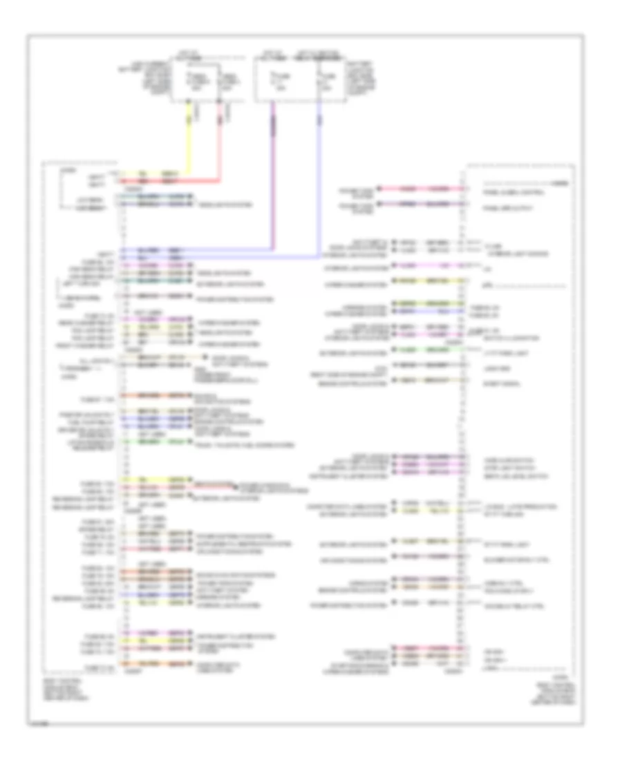
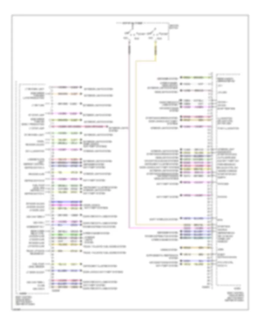
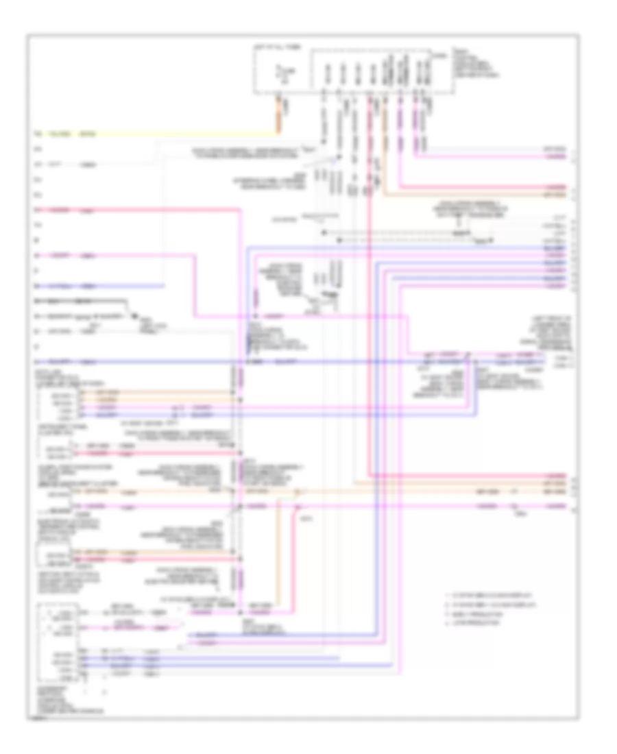
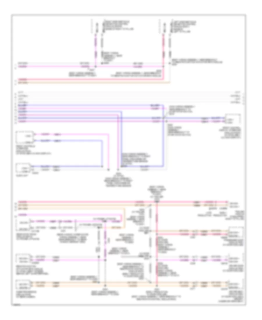
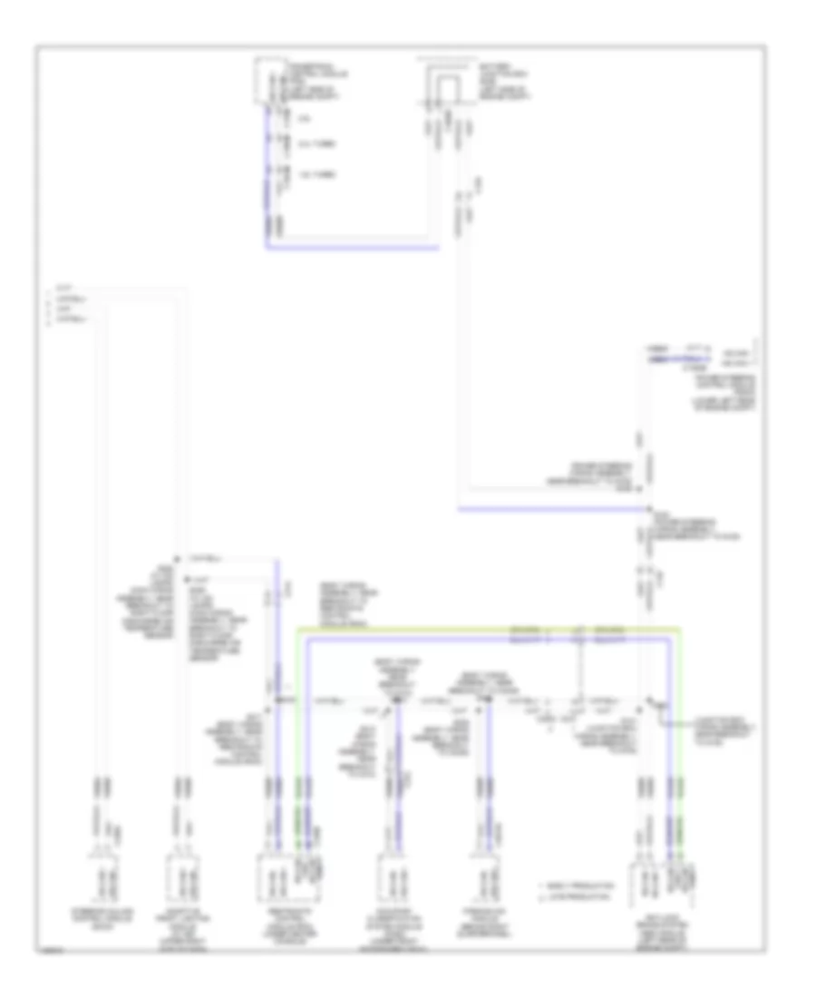
BODY CONTROL MODULES
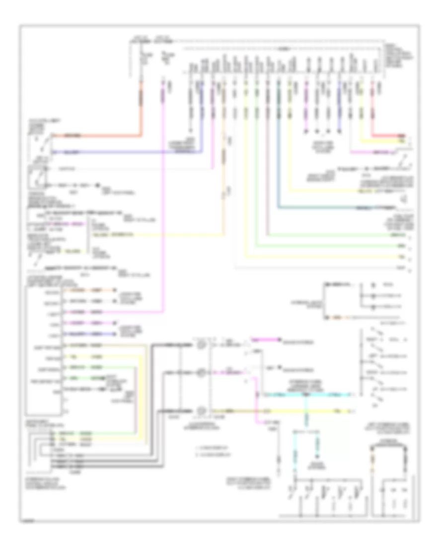
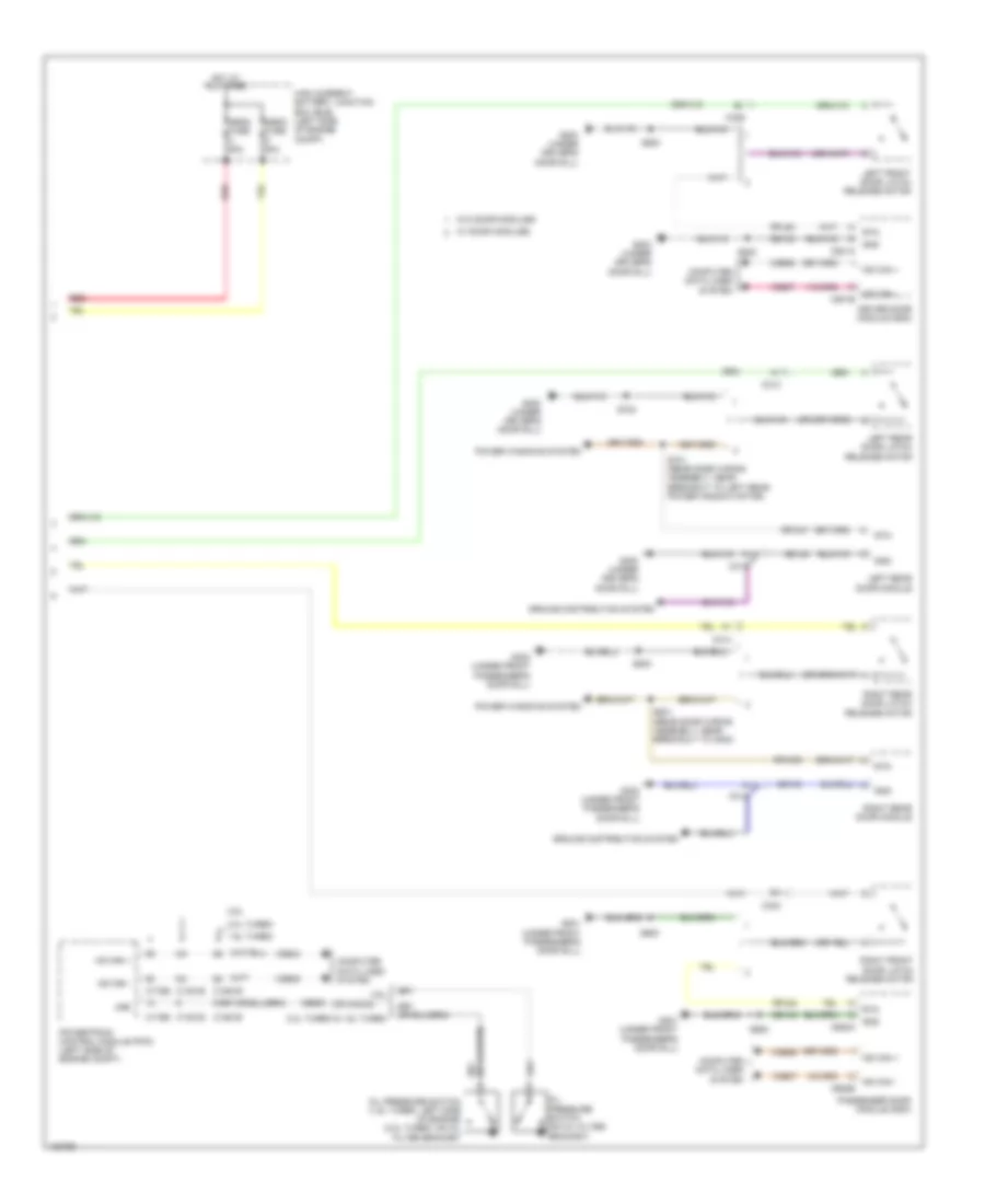
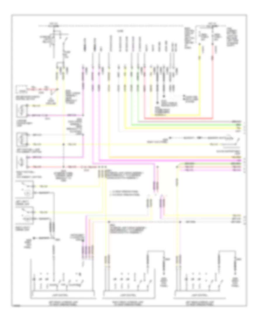
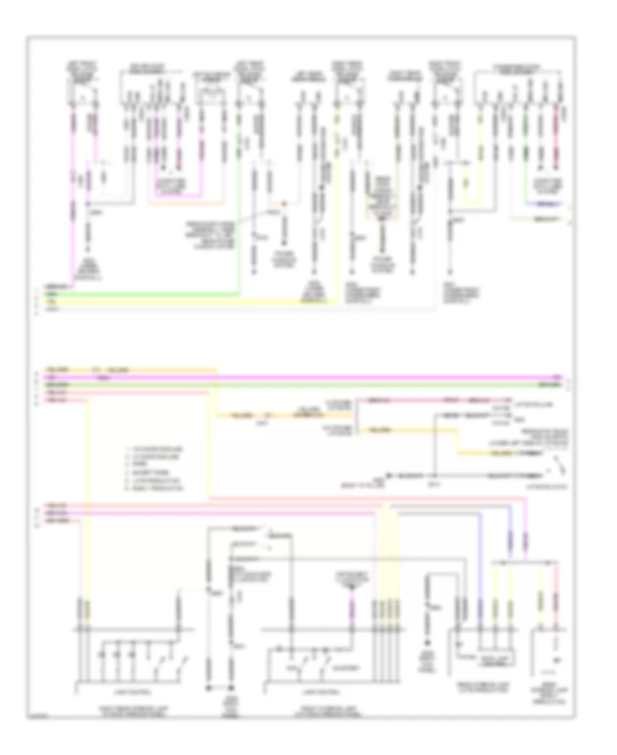
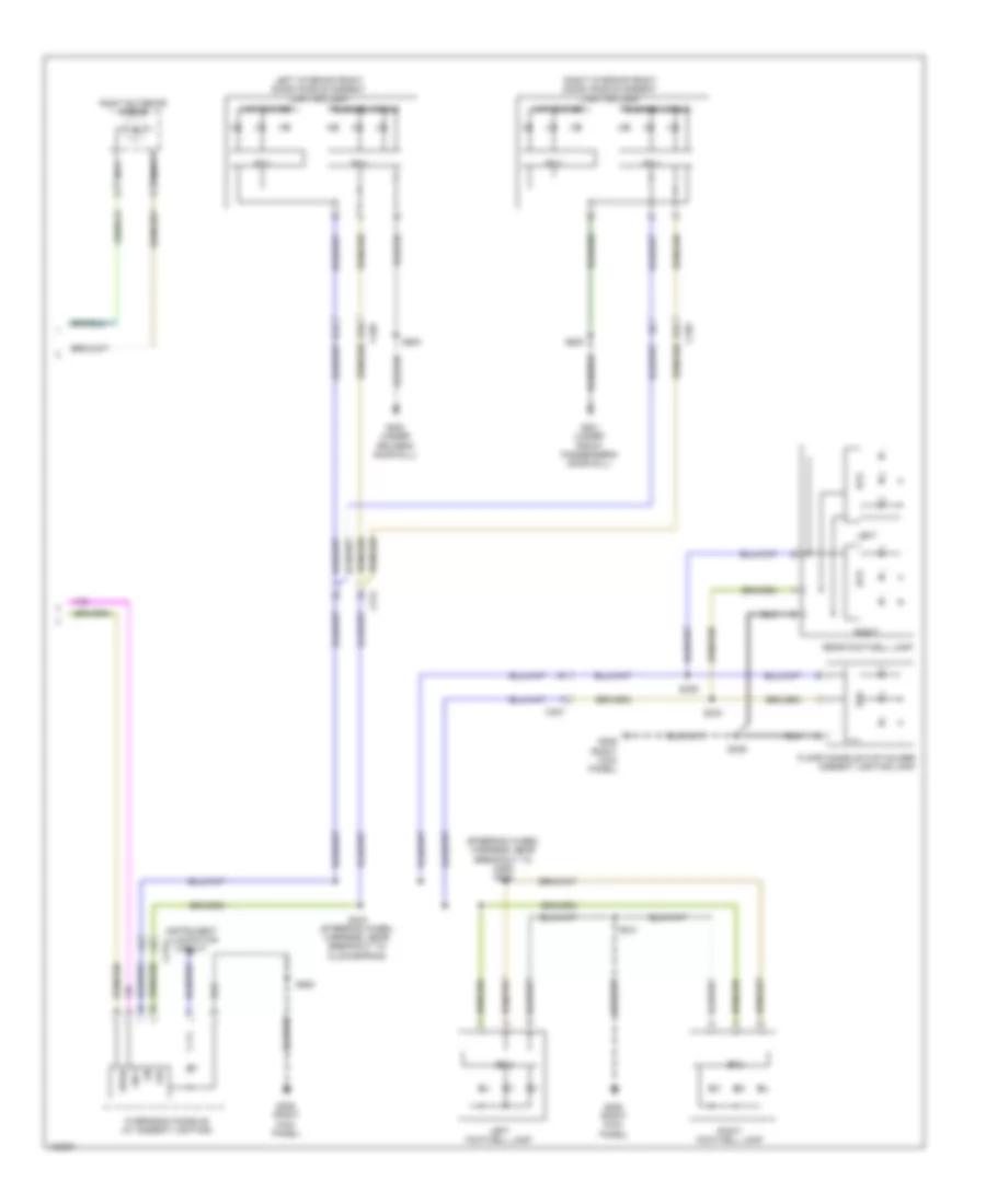
Body Control Modules Wiring Diagram (1 of 2) for Ford Escape S 2014
List of elements for Body Control Modules Wiring Diagram (1 of 2) for Ford Escape S 2014:
- (late production)
- (not used)
- Acc delay relay ctrl
- Air conditioning system
- All lock rly
- Anti-theft & door locks systems
- Anti-theft system
- Battery junction box (bjb) (left side of engine compt)
- Blower motor rly ctrl
- Body control module (bcm) (bottom right center of dash)
- Brk fluid level switch
- C1617d
- C1617j
- C2280a
- C2280d
- C2280e
- C2280f
- C2280g
- C2280h
- Cbb41
- Cbp01
- Cbp56
- Cbp59
- Cbp60
- Cbp62
- Cbp76
- Cbp80
- Cbp85
- Cbp86
- Ccb08
- Cdc01
- Cdc56
- Ce436
- Ch123
- Clf02
- Clf03
- Clf04
- Clf05
- Clf29
- Clf34
- Cls06
- Cls07
- Cls21
- Cls25
- Cls45
- Cmc19
- Cmc28
- Computer data lines system
- Cpl25
- Cpl51
- Cpl75
- Cpl76
- Cpl84
- Cpr90
- Crh04
- Crw23
- Crw24
- Door locks & anti-theft systems
- Driver dr unlck rly spare relay
- Engine controls system
- Event signal
- Exterior lights system
- Fog lamp relay
- Front washer relay
- Fuel pump relay
- Fuse 20a
- Fuse 30a
- Fuse 59, 5a
- Fuse 60, 10a
- Fuse 61, 20a
- Fuse 62, 5a
- Fuse 63, 10a
- Fuse 67, 7.5a
- Fuse 69, 5a
- Fuse 71, 10a
- Fuse 72, 7.5a
- Fuse 73, 5a
- Fuse 78, 5a
- Fuse 79, 15a
- Fuse 80, 20a
- Fuse 81, 5a
- Fuse 85, 7.5a
- Fuse 86, 10a
- G103 (right side of engine compt)
- G200 (under front passenger's door sill)
- Gd123
- Gd140
- Headlights system
- High beam relay
- High current battery junction box (bjb) (left side of engine compt)
- Hood ajar switch
- Horn rly ctrl
- Horns system
- Hot at all times
- Hot w/ ignition relay energized
- Ign rly ctrl
- Instrument cluster system
- Interior light dimming
- Interior lights system
- K-line
- Left turn sig
- Liftgate/decklid release relay
- Lin
- Lin 8
- Lin bus
- Logic gnd
- Low beam
- Lt ft park light
- Mega fuse 4 50a
- Mega fuse 9 50a
- Micro
- Mirrors system
- Ms can +
- Ms can -
- Panel global control
- Panel spd output
- Pass dr unlock rly
- Pcm wake up sply
- Power distribution system
- Power tops system
- Power windows & interior lights systems
- Pwr gnd
- Rear washer relay
- Red
- Reversing lamp relay
- Rt ft park light
- Rt ft turn sig
- Sbb11
- Sbb17
- Sbb18
- Sbp06
- Sbp07
- Sbp08
- Sbp21
- Sbp26
- Sbp71
- Sbp78
- Seats system
- Sound & navigation systems
- Spare relay
- Starting/charging & wiper/washer systems
- Stop light switch
- Switch illumination
- Trunk, tailgate, fuel doors system
- Vbatt
- Vdb06
- Vdb07
- Ve518
- Vln04
- Vln30
- Vln33
- Vmc05
- Vmp35
- Vrt22
- Vrw26
- Wiper/washer system
Body Control Modules Wiring Diagram (2 of 2) for Ford Escape S 2014
List of elements for Body Control Modules Wiring Diagram (2 of 2) for Ford Escape S 2014:
- (or cls45)
- Acc
- Acc/run
- Accessory rly
- Air conditioning system
- Anti-theft system
- Aud anti theft sw
- Autolamps sns
- Body control module (bcm) (bottom right center of dash)
- Btsi
- C2280b
- C2280c
- Cdc03
- Cdc30
- Cdc32
- Cdc33
- Cet53
- Chmsl
- Chp01
- Cls04
- Cls17
- Cls23
- Cls27
- Cls32
- Cls44
- Cls45
- Cmc25
- Computer data lines system
- Cpk28
- Cpk29
- Cpk30
- Cpk31
- Cpk34
- Cpk35
- Cpk36
- Cpl26
- Cpl30
- Cpl31
- Cpl35
- Cpl36
- Cpl38
- Cpl39
- Cpl41
- Cpl42
- Cpl43
- Cpl44
- Cpl45
- Cpl87
- Cr115
- Crd02
- Crd04
- Crd09
- Crh03
- Crw02
- Crw10
- Defogger system
- Defroster sw
- Door locks & anti-theft systems
- Dr unlck ctrl sw
- Evap temp sns
- Event notification sig
- Exterior lights system
- Exterior lights system door locks & anti-theft systems
- Fuel pump level gnd keypad illu
- Fuel pump level sensor
- Hazard warning
- Headlights system
- Horn
- Horns system
- Hot at all times
- Hs can +
- Hs can -
- Ignition switch
- Illumination dr lock ctrl sw ind (led)
- Instrument cluster system
- Interior light dimming rtn start/stop sw2
- Interior lights system
- Ip sw illumination
- K-line
- Key in ign sw
- Keypad switch a
- Keypad switch b
- Keypad switch c
- Lf door ajar
- Lf door lock
- Lf door unlock
- License plate light defrost control
- Liftgate ajar
- Lin (lsm)
- Lin 1
- Lr door ajar
- Lr door unlock
- Lt rr park light
- Lt rr turn
- Lt stop lamp
- Micro
- Msx can h
- Msx can l
- Msx can term h
- Msx can term l
- Navigation & sound systems
- Off
- Park brake sw
- Pats gnd
- Pats rx
- Pats tx
- Power distribution system
- Ptc htr ctrl
- Rear window defroster ind
- Rear wiper relay ctrl
- Rf door ajar
- Rf door unlock
- Rlf14
- Rmc32
- Rr door ajar
- Rr door unlock
- Rrt25
- Rt rr park light
- Rt stop lamp
- Run
- Shift interlock system
- Side mirror turn end (late production)
- Side mirror turn ind (early production)
- Sigrtn
- Start
- Start/run
- Start/stop sw1
- Starting/charging system
- Starting/charging system air conditioning & headlights systems
- Sw illumination
- Trunk liftgate release sw
- Trunk, tailgate, fuel doors system
- Vdb04
- Vdb05
- Vdb06
- Vdb07
- Vh406
- Vlf14
- Vlf25
- Vln04
- Vln33
- Vmc11
- Vmc34
- Vmp19
- Vpl56
- Vrt23
- Vrt24
- Wiper limp home sw
- Wiper/washer system
- Wiper/washer, headlights & exterior lights systems
COMPUTER DATA LINES
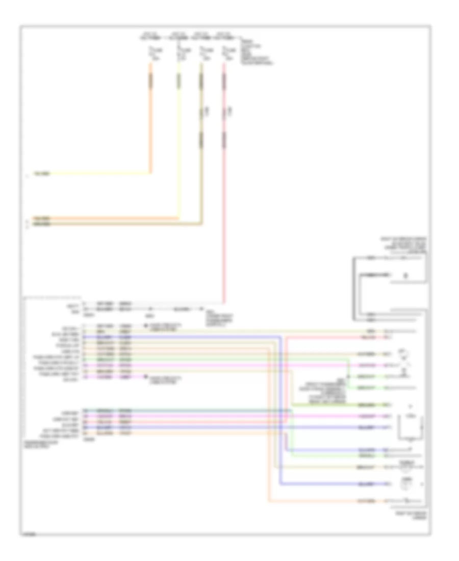
Computer Data Lines Wiring Diagram (1 of 3) for Ford Escape S 2014
List of elements for Computer Data Lines Wiring Diagram (1 of 3) for Ford Escape S 2014:
- (left front of luggage area) (w/ sony sound) audio digital signal processing (dsp) module
- (main wiring assembly, near breakout to
- (main wiring assembly, near breakout to electric booster heater)
- (main wiring assembly, near breakout to front passive start antenna) s212
- (main wiring assembly, near breakout to panel/floor mode door actuator)
- (main wiring assembly, near breakout to passenger air bag deactivation (pad) indicator) s222
- (main wiring assembly, near breakout to passive anti-theft transceiver)
- (w/ sony sound)
- (w/ sync gen 2 (8 display)) s226
- Accessory protocol interface module (apim) (under center console)
- Body control module (bcm) (bottom right center of dash)
- C210
- C214
- C2280a
- C2280b
- C2280c
- C2280f
- C228b
- C2357a
- C3053
- C4326a
- C934
- Data link connector (dlc) (lower left side of dash)
- Early production
- Electric booster heater)
- Electronic automatic temperature control (eatc) module (manual a/c)
- Fuse 5a
- G204 (left kick panel)
- Gd133
- Gd138
- Global positioning system module (gpsm) (w/ gps) (behind instrument cluster)
- Heating ventilation & air conditioning (hvac) control module (automatic a/c)
- Hot at all times
- Hs can +
- Hs can -
- I can +
- I can + ms can +
- I can -
- I can - ms can -
- Instrument panel cluster (ipc)
- Late production
- Micro
- Ms can +
- Ms can -
- Ms can+
- Ms can-
- Msx can +
- Msx can -
- S209
- S210 (main wiring assembly, in breakout to data link connector (dlc))
- S211
- S223 (main wiring assembly, near breakout to passenger air bag deactivation (pad) indicator)
- S224
- S225
- S227 (w/ sync gen 2 (8 inch display))
- S230
- S231 (w/ sync)
- S236 (steering wheel harness, near breakout to c260)
- S237
- S306 (w/ sony sound) (body wiring assembly, near breakout to c311)
- S307 (w/ sony sound) (body wiring assembly, near breakout to c311)
- Sbp26
- Termination msx can +
- Termination msx can -
- Vdb04
- Vdb05
- Vdb06
- Vdb07
- Vdb13
- Vdb14
- W/ sync gen 1 (4.2 inch display)
- W/ sync gen 2 (8 inch display)
- W/o sync
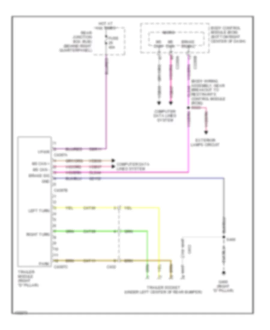
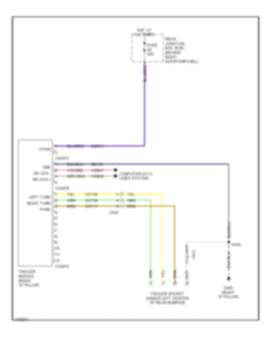
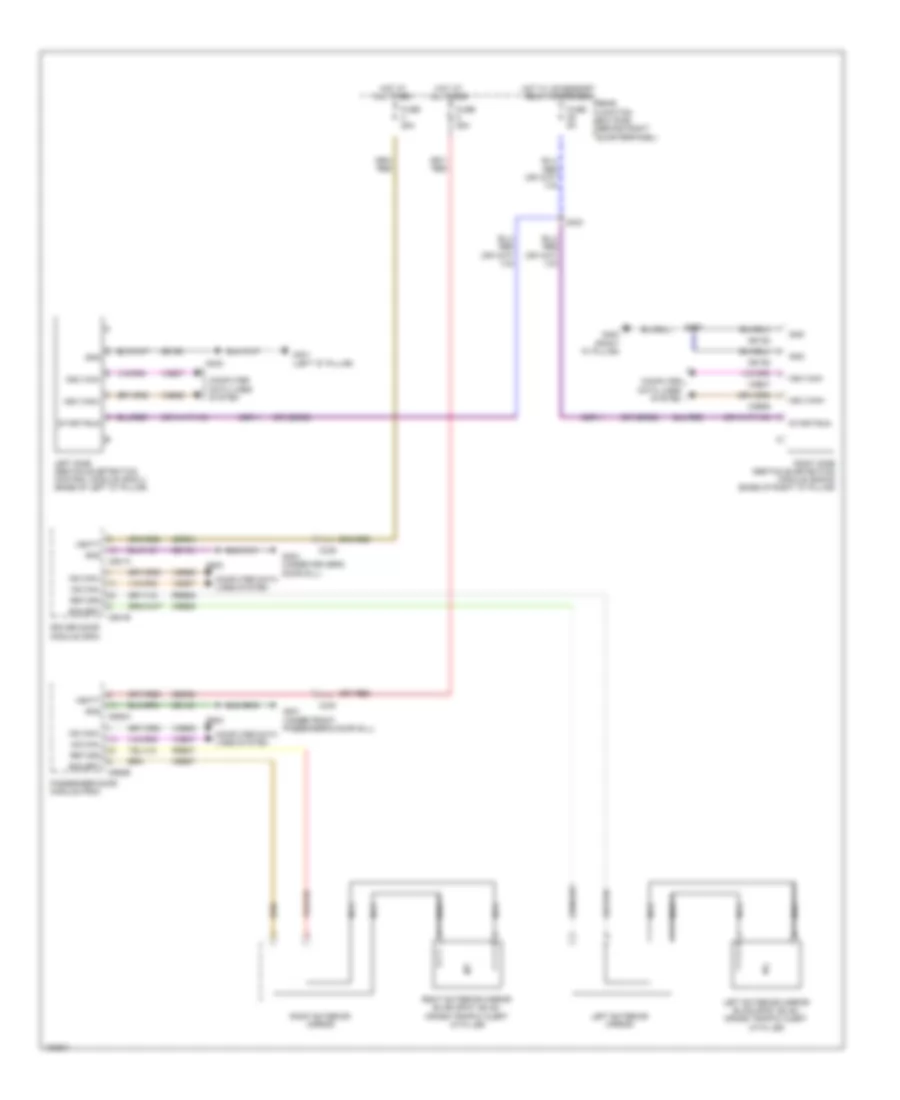
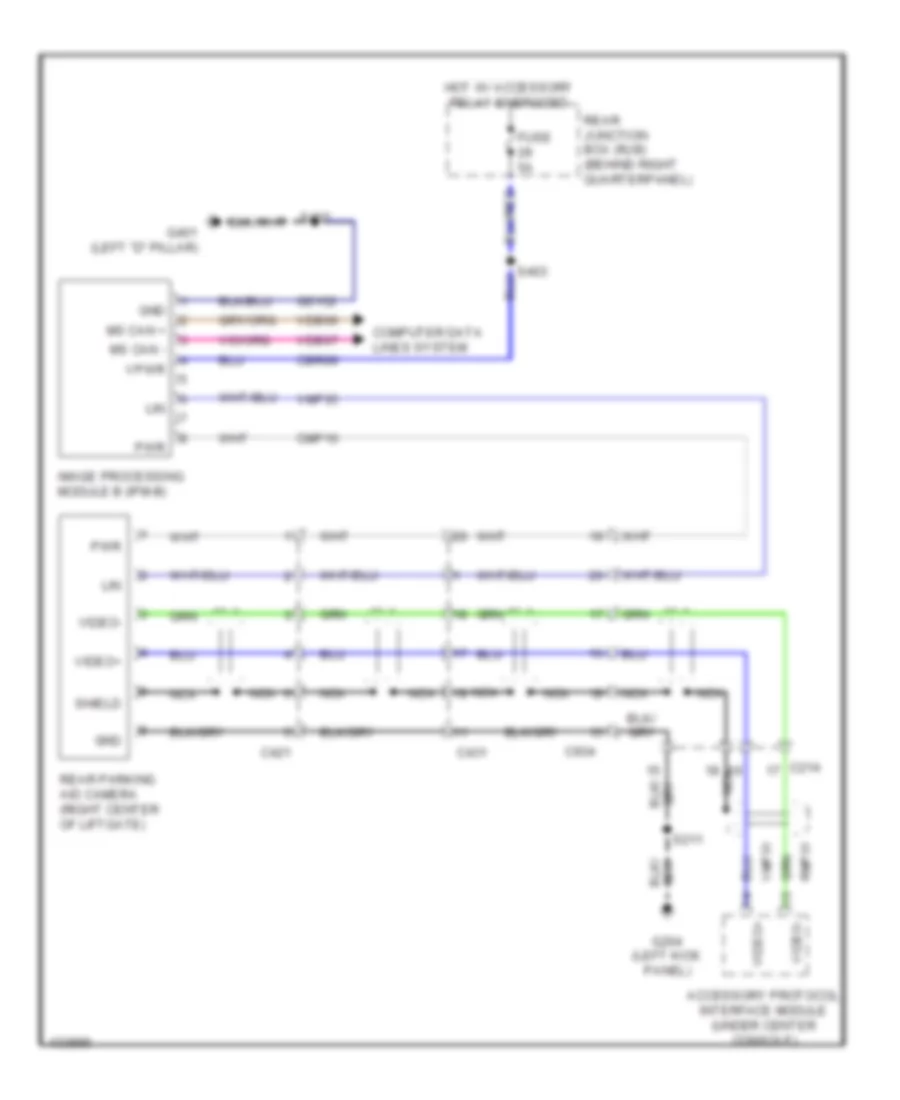
Computer Data Lines Wiring Diagram (2 of 3) for Ford Escape S 2014
List of elements for Computer Data Lines Wiring Diagram (2 of 3) for Ford Escape S 2014:
- (body wiring assembly, near breakout to c214)
- (body wiring assembly, near breakout to c405) s302
- (body wiring assembly, near breakout to g200)
- (body wiring assembly, near breakout to g301)
- (body wiring assembly, near breakout to g301) (w/ trailer tow) s405
- (body wiring assembly, near breakout to remote function actuator (rfa) module) s408
- (body wiring assembly, near breakout to restraints control module (rcm)) (early production w/ door modules) s320
- (main wiring assembly, near breakout to right panel discharge air temperature sensor) (w/ sync) s233
- (main wiring assembly, near breakout to start/stop switch) s219
- (rear window wiper motor wiring assembly, near near breakout to rear window defrost grid)
- (w/ door modules) s201
- (w/ door modules) s324
- (w/ power liftgate) s411
- (w/ power liftgate) s412
- Audio unit
- C240a
- C311
- C339
- C340
- C341b
- C4174b
- C431
- C4392d
- C4397b
- C501b
- C652b
- C934
- Driver door module (ddm) (w/ door modules)
- Driver seat module (dsm) (w/ door modules & memory) (under driver's seat)
- Early production
- Front control/ display interface module (fcdim) (w/ sync gen 1 (4.2 inch display))
- Front controls interface module (fcim) (w/ sync gen 2 (8 inch display))
- I can +
- I can -
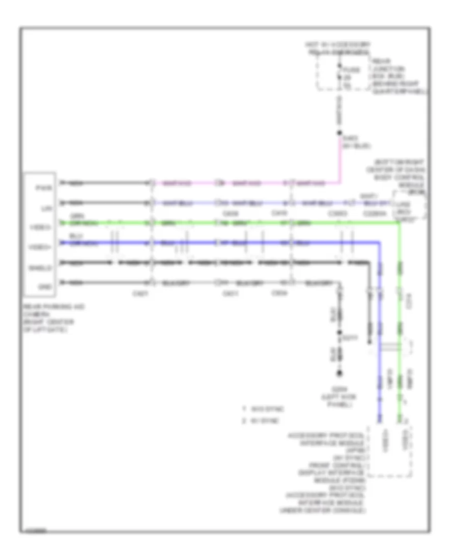
- Image processing module (pm-b) (w/ rear camera)
- Late production
- Left side obstacle detection control module (sod-l) (base of left "d" pillar)
- Ms can +
- Ms can -
- Msx can +
- Msx can -
- Near breakout to g200)
- Passenger door module (pdm) (w/ door modules)
- Rear gate trunk module (rgtm) (w/ power liftgate)
- Remote function actuator (rfa) module (w/ intelligent access) (behind left quarterpanel)
- Right side obstacle detection control module (sod-r) (base of right "d" pillar)
- S220 (main wiring assembly, near breakout to start/stop switch)
- S234 (w/ sync) (main wiring assembly, near breakout to right panel discharge air temperature sensor)
- S303 (body wiring assembly, near breakout to c405)
- S321 (early production w/ door modules) (body wiring assembly, near breakout to restraints control module (rcm))
- S325 (w/ door modules) (body wiring assembly, near breakout to c214)
- S404 (w/ trailer tow) (body wiring assembly, near breakout to g301)
- S407
- S409 (body wiring assembly, near breakout to remote function actuator (rfa) module)
- Trailer module (if equipped) (right "d" pillar)
- Vdb06
- Vdb06 (body wiring assembly, near breakout to g301) s406
- Vdb07
- Vdb13
- Vdb14
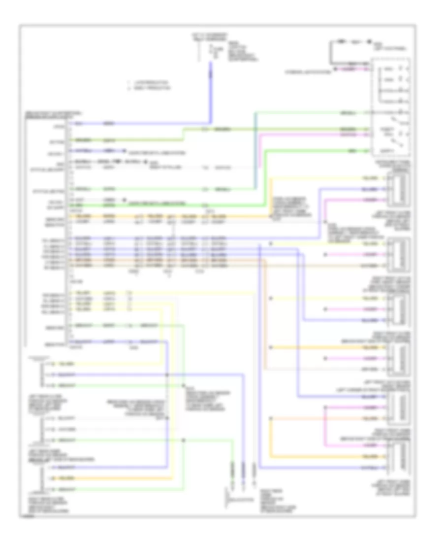
Computer Data Lines Wiring Diagram (3 of 3) for Ford Escape S 2014
List of elements for Computer Data Lines Wiring Diagram (3 of 3) for Ford Escape S 2014:
- (body wiring assembly, near breakout to c3049) s308
- (body wiring assembly, near breakout to c312)
- (body wiring assembly, near breakout to restraints control module (rcm))
- (junction box wiring assembly, near breakout to g105)
- (power steering wiring assembly, near breakout to g108) s153
- 1.6l turbo
- 2.0l turbo
- 2.5l
- Adaptive front lighting module (w/ hid) (upper right side of dash)
- Anti-lock brake system (abs) module (left rear of engine compt)
- Battery junction box (bjb) (left side of engine compt)
- C1035c
- C133
- C1381b
- C1463b
- C1551b
- C175b
- C210
- C214
- C226a
- C3053
- C310b
- C312
- C4014a
- Early production
- Hs can +
- Hs can -
- Late production
- Near breakout to g108)
- Occupant classification system module (ocsm) (under front passenger's seat)
- Parking aid module (behind right quarterpanel)
- Power steering control module (pscm) (lower left rear of engine compt)
- Powertrain control module (pcm) (left side of engine compt)
- Restraints control module (rcm) (under center console)
- S141 (junction box wiring assembly, near breakout to g105)
- S142
- S228 (w/ hid lamps) (main wiring assembly, near breakout to right floor discharge air temperature sensor)
- S229 (w/ hid lamps) (main wiring assembly, near breakout to right floor discharge air temperature sensor)
- S309 (body wiring assembly, near breakout to c3049)
- S312
- S313 (body wiring assembly, near breakout to c312)
- S317 (body wiring assembly, near breakout to restraints control module (rcm))
- Steering column control module (sccm)
- Vca23
- Vca24
- Vdb04
- Vdb05
- Yaw + hs can
- Yaw - hs can
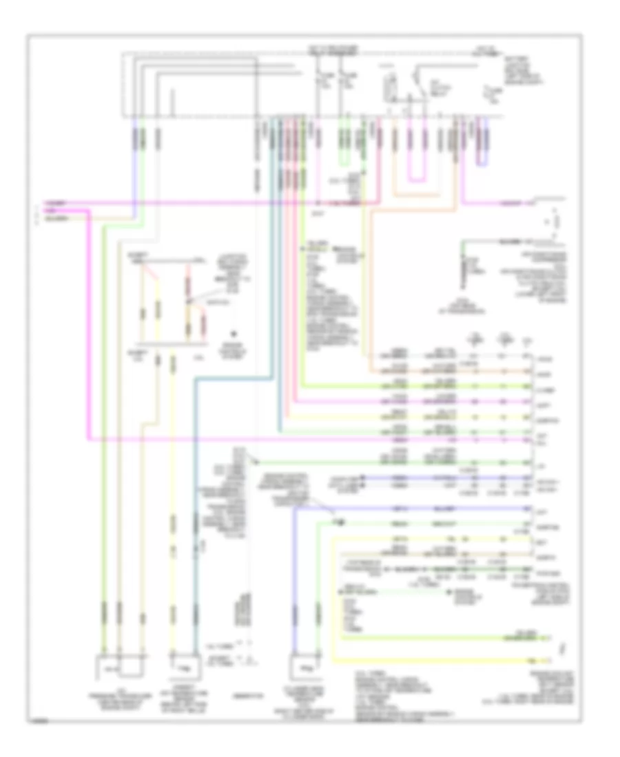
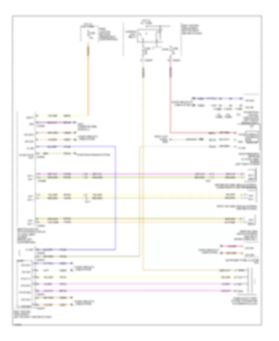
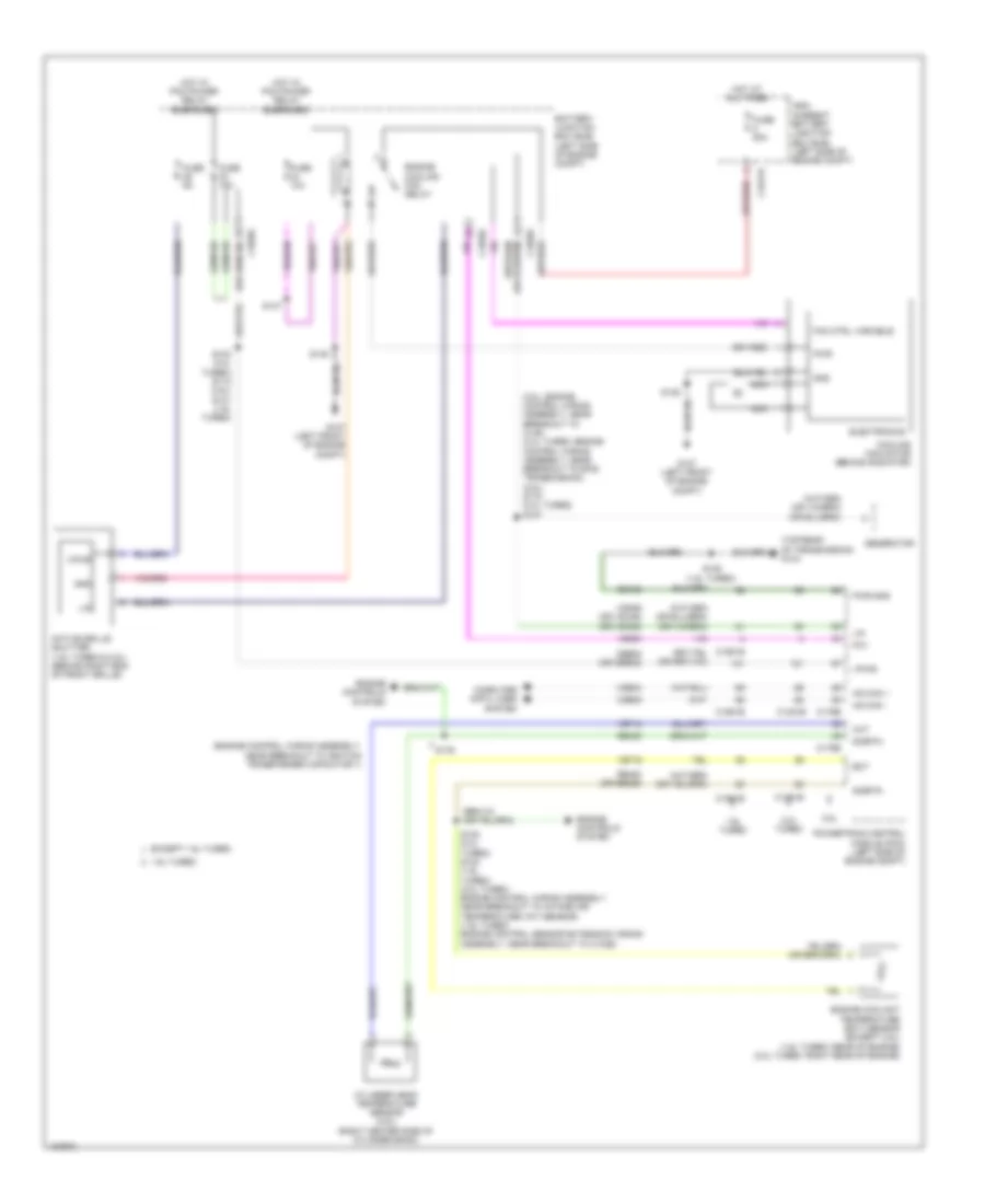
COOLING FAN
Cooling Fan Wiring Diagram for Ford Escape S 2014
List of elements for Cooling Fan Wiring Diagram for Ford Escape S 2014:
- (2.5l: engine control wiring assembly, near breakout to c145) (2.0l turbo: engine control wiring assembly, near breakout to 6f35 transmission) (2.5l) s115 (2.0l turbo) s107
- (engine control wiring assembly, near breakout to ignition transformer capacitor 1)
- (top rear of transmission) g104
- 1.6l turbo
- 2.0l turbo
- 2.5l
- Active grille shutter (1.6l turbo & 2.5l) (behind right end of front grille)
- Battery junction box (bjb) (left side of engine compt)
- C1035c
- C1381b
- C1381e
- C1551b
- C1551e
- C1617h
- C175b
- C175e
- Cbb08 (or cbb32)
- Cht
- Computer data lines system
- Cooling fan motor (behind radiator)
- Cylinder head temperature sensor (2.5l) (right center side of cylinder bank)
- Ect
- Electronics
- Engine controls system
- Engine coolant temperature (ect) sensor (except 2.5l) (1.6l turbo: rear of engine) (2.0l turbo: right rear of engine)
- Engine cooling fan relay
- Except 1.6l turbo
- Fan ctrl variable
- Fcv
- Fuse 10a
- Fuse 15a
- Fuse 50a
- Fuse 5a
- G107 (left front of engine compt)
- Gd120
- Generator
- Gnd
- High current battery junction box (bjb) (left side of engine compt)
- Hot at all times
- Hot w/ pcm power relay energized
- Hs can +
- Hs can -
- Lin
- Nca
- Powertrain control module (pcm) (left side of engine compt)
- Pwr
- Pwr gnd
- Re405
- Re454 (or re329)
- S103 (2.0l turbo) s112 (2.5l) s131 (1.6l turbo)
- S108 (2.0l turbo) s123 (1.6l turbo) (2.0l turbo: engine control wiring assembly, near breakout to intake air temperature (iat) sensor) (1.6l turbo: engine control sensor extension wiring assembly, near breakout to c1026)
- S125 (1.6l turbo)
- S147
- S148
- S149
- S176
- Sigrtn
- Vdb04
- Vdb05
- Vdn06 (or vdc46) (or vdn08)
- Ve203
- Ve712
- Ve716
- Vpwr
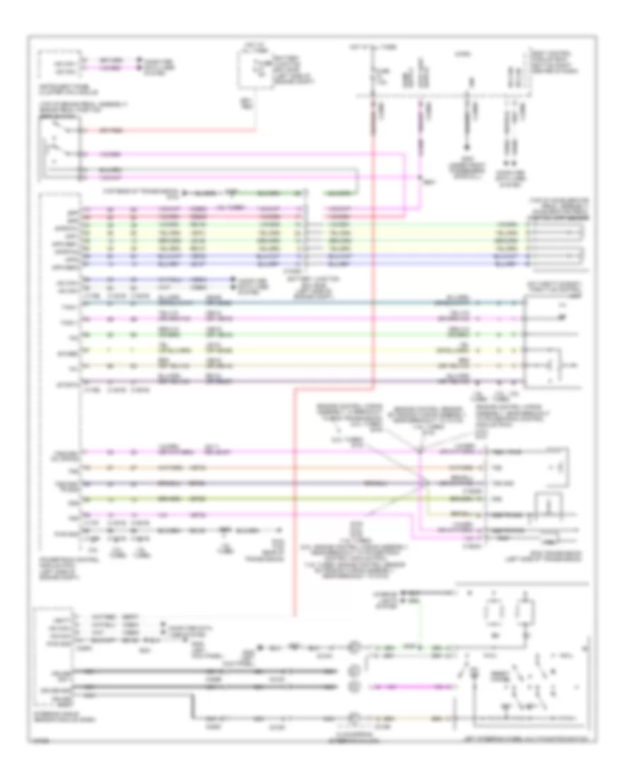
CRUISE CONTROL
Cruise Control Wiring Diagram for Ford Escape S 2014
List of elements for Cruise Control Wiring Diagram for Ford Escape S 2014:
- (2.0l turbo) s104
- (engine control sensor extension wiring assembly, near breakout to c1019) (1.6l turbo) s132
- (engine control wiring assembly, in breakout to 6f35 transmission) (2.0l turbo) s106
- (engine control wiring assembly, near breakout to powertrain control module (pcm)) (2.5l) s101
- (on throttle body) throttle control unit
- (top of accelerator pedal assembly) accelerator pedal position (app) sensor
- (top of brake pedal assembly) brake pedal position (bpp) switch
- (top rear of transmission) g104
- 1.6l
- 1.6l turbo
- 2.0l
- 2.5l
- 6f35 transmission (left side of transmission)
- App1
- App2
- Apprtn1
- Apprtn2
- Appvref1
- Appvref2
- Battery junction box (bjb) (left side of engine compt)
- Body control module (bcm) (bottom right center of dash)
- Bpp
- Bps
- C1035c
- C1381b
- C1381e
- C1520a
- C1520b
- C1551b
- C1551e
- C175b
- C175e
- C175t
- C218a
- C218b
- C218c
- C218d
- C226a
- C226b
- C226c
- C2280a
- C2280c
- C2280e
- C2280f
- Ccb08
- Ce412 (or ve819)
- Ce426 (or le428)
- Ces09
- Clockspring (steering column)
- Computer data lines system
- Cruise gnd
- Cruise sig 1
- Cruise sig 2
- Etcref
- Etcrtn
- Fuse 5a
- Fuse 7.5a
- G104 (top rear of transmission)
- G200 (under front passenger's door sill)
- G205 (left kick panel)
- Gd120
- Gd138
- Gnd
- Hot at all times
- Hs can+
- Hs can-
- Instrument panel cluster (ipc) module
- Interior lights system
- Le111 (or le157)
- Le134 (or ce426)
- Le136
- Le137
- Left steering wheel multi-function switch
- Micro
- Ms can +
- Ms can -
- Nca
- On/ off
- Oss
- Oss/tr gnd
- Oss/tr pwr
- Powertrain control module (pcm) (left side of engine compt)
- Pwr gnd
- Re134 (or re427)
- Re136
- Re137
- Reset/ cancel
- Ret24
- S102 (2.5l) s130 (1.6l turbo) (2.5l: engine control wiring assembly, near breakout to powertrain control module (pcm)) (1.6l turbo: engine control sensor extension wiring assembly, near breakout to g104)
- S125
- S221
- S235
- S250
- Sbp07
- Set+
- Set-
- Steering angle sensor module (sasm)
- Switch stop light
- Tacm +
- Tacm -
- Tp1
- Tp2
- Tr-p
- Trp
- Trs
- Tss
- Tss gnd
- Tss v pwr
- Tss/oss/ tr gnd
- Tss/oss/ tr vppwr
- Turbo
- Vbatt
- Vdb04
- Vdb05
- Ve701
- Ve702
- Ve818 (or ce412)
- Ve819 (or ve818)
- Vet26
- Vet32
- Vet33
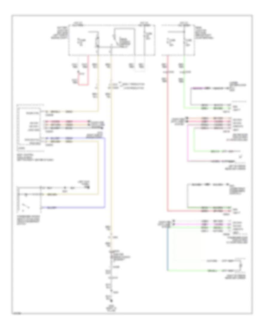
DEFOGGERS
Defoggers Wiring Diagram for Ford Escape S 2014
List of elements for Defoggers Wiring Diagram for Ford Escape S 2014:
- (left kick panel) g205
- (under driver's door sill) g203
- Battery junction box (bjb) (left side of engine compt)
- Body control module (bcm) (bottom right center of dash)
- C210
- C2280a
- C2280b
- C2280c
- C3053
- C339 a14
- C340 a14
- C402a
- C402b
- C410
- C501a
- C501b
- C652a
- C652b
- C934
- Computer data lines system
- Crd02
- Crd04
- Crd09
- Crd13
- Crd14
- Driver door module (ddm) (w/ door modules)
- Early production
- Fuse 20a
- Fuse 25a
- Fuse 5a
- G103 (right side of engine compt)
- G201 (under front passenger's door sill)
- G400 (right "d" pillar)
- Gd123
- Gd134
- Gd140
- Gnd
- Heat
- Heated rear window element
- Hot at all times
- Late production
- Left exterior rearview mirror
- Logic gnd
- Micro
- Mirr rtn
- Ms can +
- Ms can -
- Ms can+
- Ms can-
- Nca
- Passenger air bag deactivation (pad) indicator/defrost switch
- Passenger door module (pdm) (w/ door modules)
- Rear junction box (rjb) (behind right quarterpanel)
- Rear window defrost relay
- Right exterior rearview mirror
- Rpm05
- Rpm08
- Rwd ind
- Rwd switch
- Rwdr ctrl
- S144
- S221
- S400
- S500
- S600
- Sbr04
- Sbr05
- Vbatt
- Vdb06
- Vdb07
- Vdbo6
- Vdbo7
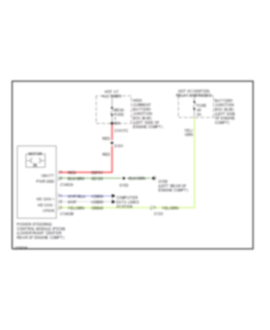
ELECTRONIC POWER STEERING
Electronic Power Steering Wiring Diagram for Ford Escape S 2014
List of elements for Electronic Power Steering Wiring Diagram for Ford Escape S 2014:
- Battery junction box (bjb) (left side of engine compt)
- C133
- C1463a
- C1463b
- C1617c
- Cbb40
- Computer data lines system
- Fuse 5a
- G108 (left rear of engine compt)
- Gd120
- High current battery junction box (bjb) (left side of engine compt)
- Hot at all times
- Hot w/ ignition relay energized
- Hs can +
- Hs can -
- Mega fuse 80a
- Motor
- Power steering control module (pscm) (lower right center rear of engine compt)
- Pwr gnd
- Red
- S151
- S152
- Sbf01
- Vbatt
- Vdb04
- Vdb05
- Vpwr
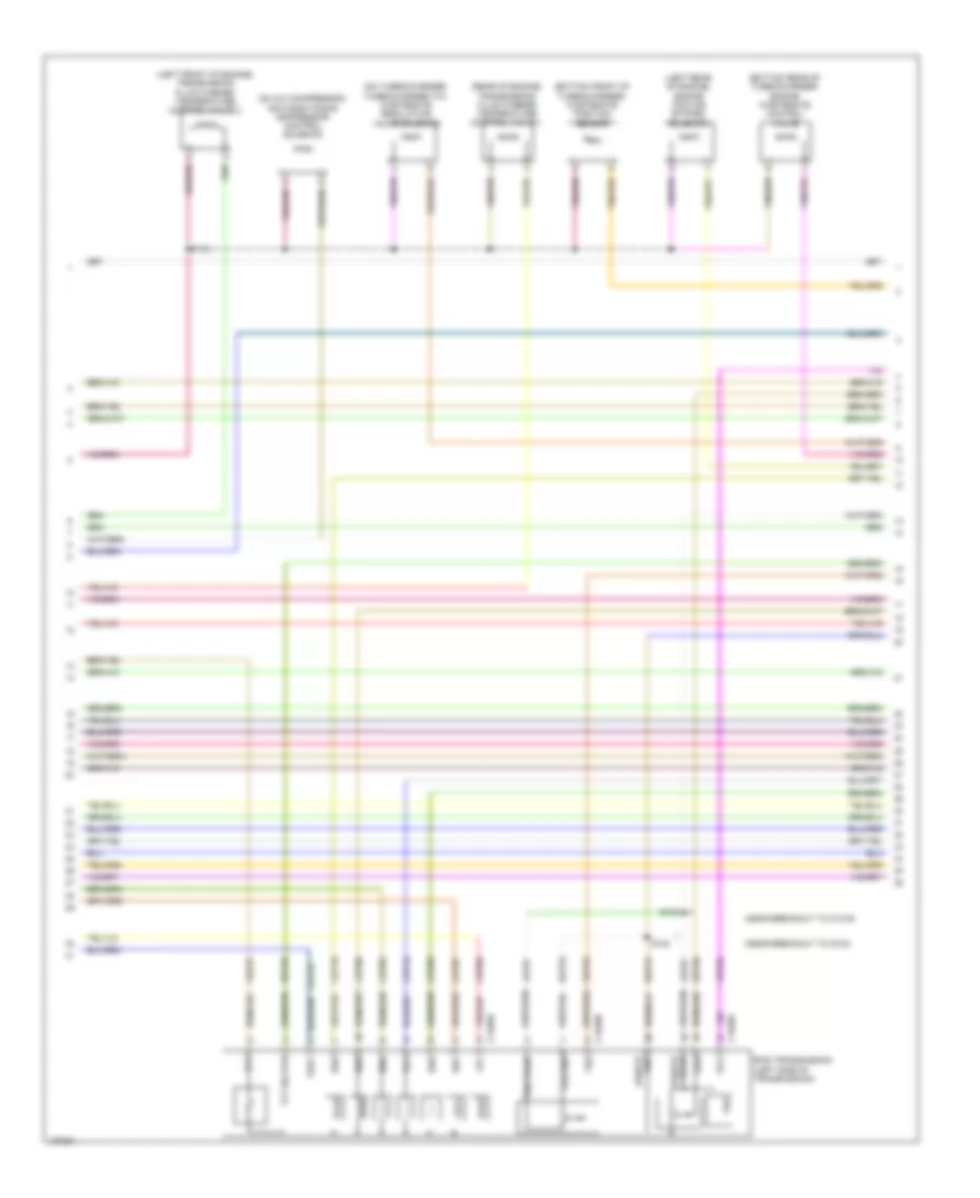
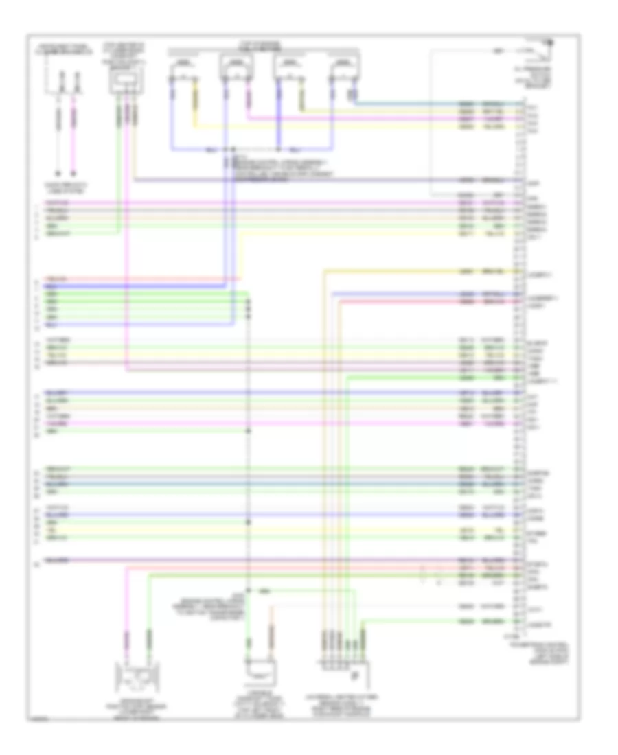
ENGINE PERFORMANCE
1.6L TURBO
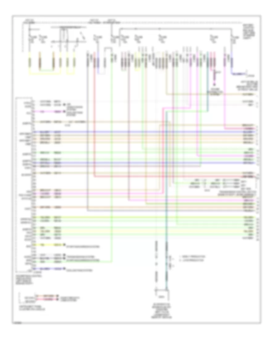
1.6L Turbo, Engine Performance Wiring Diagram (1 of 6) for Ford Escape S 2014
List of elements for 1.6L Turbo, Engine Performance Wiring Diagram (1 of 6) for Ford Escape S 2014:
- (not used)
- Accr
- Active grille shutter (behind right end of front grille)
- Air conditioning system
- Apprtn1
- Apprtn2
- Appvref1
- Appvref2
- Awdm
- Battery junction box (bjb) (left side of engine compt)
- C1035c
- C140
- C1551b
- C210
- C212
- C3053
- Cact
- Canv
- Cbb38
- Cdc12
- Cdv2
- Ce113
- Ce114
- Ce172
- Ce436
- Ch109
- Computer data lines system
- Cooling fans system
- Early production
- Evapcp
- Evaporative emission (evap) canister vent valve (under right rear of vehicle)
- Evdc
- Fcv
- Fpc
- Fpm
- Fuse 10a
- Fuse 15a
- Fuse 30a
- Fuse 5a
- Hot at all times
- Hot in start or run
- Htr12
- Instrument panel cluster (ipc) module
- Isp-r
- Late production
- Le136
- Le137
- Le230
- Lh108
- Lin
- Ms can+
- Ms can-
- Nca
- Pcm power relay
- Pcm wake
- Power distribution system
- Powertrain control module (pcm) (left side of engine compt)
- Re136
- Re137
- Re238
- Re242
- Re731
- Re804
- Ret42
- Rh107
- Sigrtn
- Smc
- Smr
- Sst gnd
- Sst+
- Sst-
- Starting/charging system
- Status
- Transmission control switch (base of shift lever assembly)
- Transmissions system
- Vcf34
- Vdc46
- Ve203
- Ve225
- Ve462
- Ve518
- Ve805
- Vpwr
- Vref
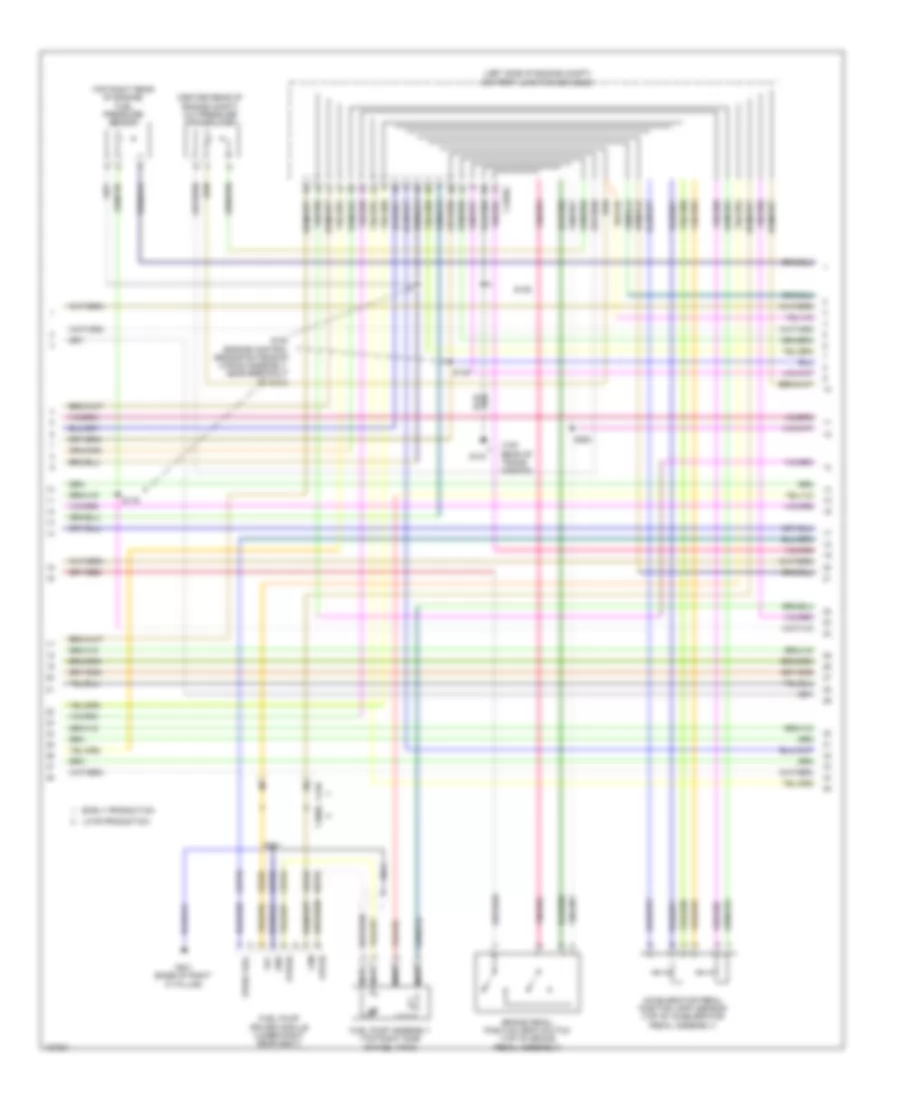
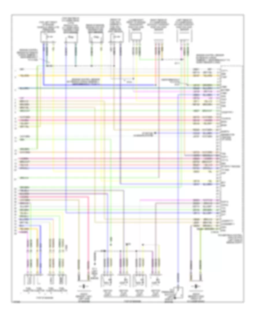
1.6L Turbo, Engine Performance Wiring Diagram (2 of 6) for Ford Escape S 2014
List of elements for 1.6L Turbo, Engine Performance Wiring Diagram (2 of 6) for Ford Escape S 2014:
- (center rear of engine compt) a/c pressure transducer
- (left side of engine compt) battery junction box (bjb)
- (top rear of trans- mission)
- (top right rear of engine) fuel pressure sensor
- Accelerator pedal position (app) sensor (top of accelerator pedal assembly)
- Brake pedal position (bpp) switch (top of brake pedal assembly)
- C1035c
- C210
- C3050
- Cbp56
- Ce515
- Early production
- Fpc
- Fpm
- Fppwr
- Fprtn
- Fuel pump assembly (top right side of fuel tank)
- Fuel pump driver module (under right rear seat)
- G104
- G301 (base of right "c" pillar)
- Gd152
- Gnd
- Late production
- Nca
- Re515
- S125
- S129
- S179
- S180 (engine control sensor extension wiring assembly, near breakout to g104)
- S250
- S301
- Ve225
- Ve518
- Vpwr fuel
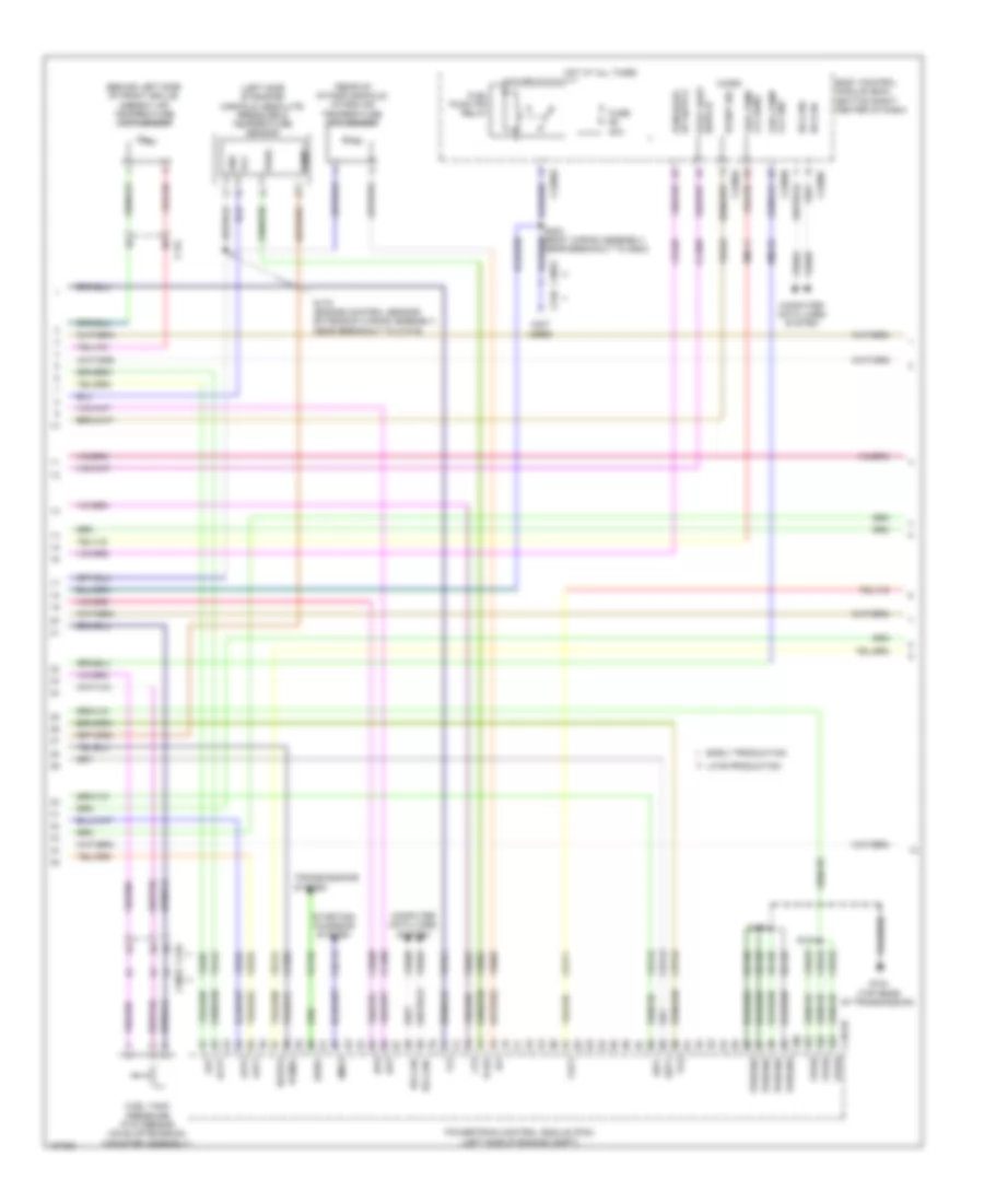
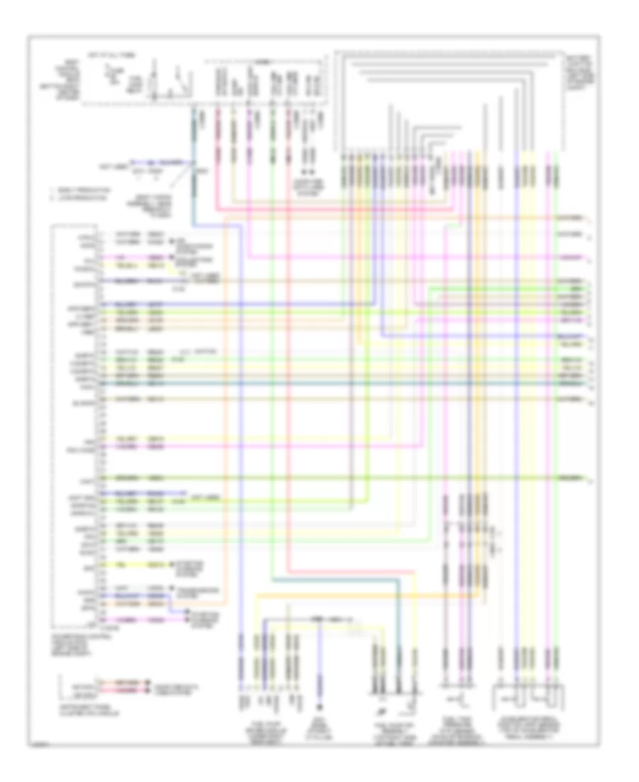
1.6L Turbo, Engine Performance Wiring Diagram (3 of 6) for Ford Escape S 2014
List of elements for 1.6L Turbo, Engine Performance Wiring Diagram (3 of 6) for Ford Escape S 2014:
- (behind left side of front grille) ambient air temperature (aat) sensor
- (left side of engine) manifold absolute pressure & temperature sensor
- (not used)
- (rear of intake manifold) intake air temperature (iat) sensor
- Aat
- Acpt
- App1
- App2
- Awdc
- Body control module (bcm) (bottom right center of dash)
- Bpp
- Bps
- C134
- C1551b
- C210
- C2280a
- C2280b
- C2280c
- C2280e
- C3053
- Cbb32
- Ccb08
- Cdc12
- Cdv1
- Ce171
- Ce302
- Ce436
- Ces09
- Cet34
- Cet42
- Cet43
- Computer data lines system
- Early production
- Event sig
- Flp
- Ftp
- Fuel pump (fp) relay
- Fuel pump lvl gnd
- Fuel tank pressure (ftp) sensor (on evap emission canister assembly)
- Fuse 20a
- G104 (top rear of transmission)
- Gd120
- Gnd
- Ho2s12
- Hot at all times
- Hs can+
- Hs can-
- Iat
- Late production
- Lvl sens fuel pump
- Micro
- Near breakout to g200)
- Pcmrc
- Powertrain control module (pcm) (left side of engine compt)
- Pres
- Pwrgnd
- Rmc32
- S125
- S131
- S178 (engine control sensor extension wiring assembly, near breakout to c1019)
- Smcs
- Sst+
- Sst-
- Starting/ charging system
- Switch stop light
- Tcbp
- Tcs
- Temp
- Transmissions system
- Vcc
- Vcf35
- Vdb04
- Vdb05
- Ve518
- Ve701
- Ve702
- Ve731
- Ve761
- Ve804
- Ve805
- Ve922
- Vh407
- Vh442
- Vmc11
- Vpwr
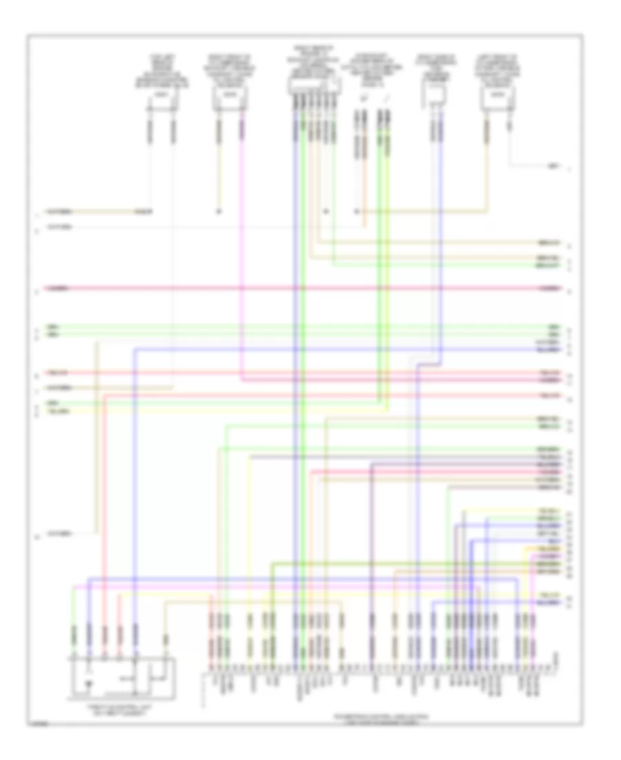
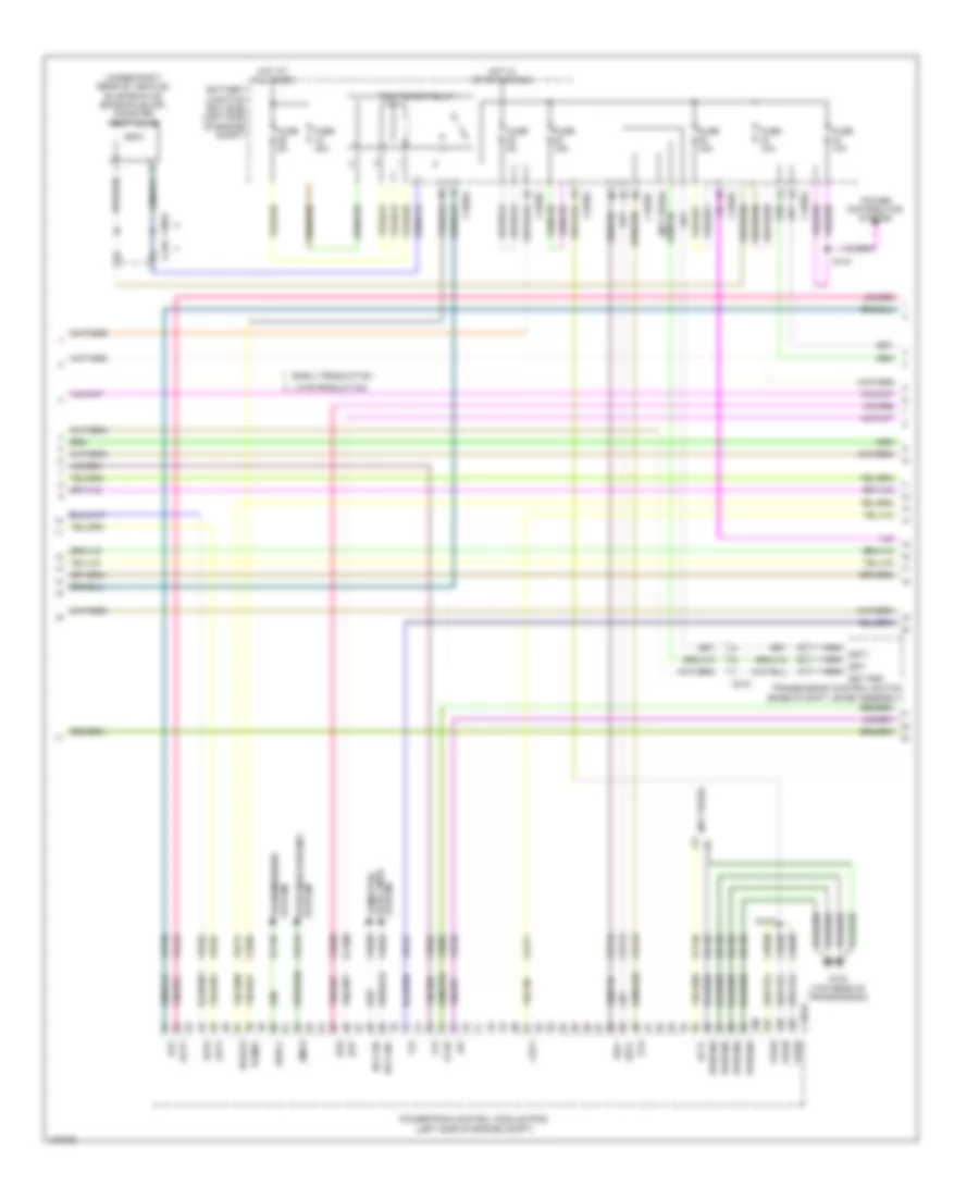
1.6L Turbo, Engine Performance Wiring Diagram (4 of 6) for Ford Escape S 2014
List of elements for 1.6L Turbo, Engine Performance Wiring Diagram (4 of 6) for Ford Escape S 2014:
- (in exhaust, downstream of catalytic converter) heated oxygen sensor (ho2s) 12
- (left front of cylinder bank) intake variable camshaft timing oil control solenoid
- (right front of cylinder bank) exhaust variable camshaft timing oil control solenoid
- (right rear of engine, in exhaust manifold) universal heated oxygen sensor (ho2s) 11
- (right side of cylinder bank) fuel metering valve
- (top left rear of engine) evaporative emission canister (evap) purge valve
- C1551e
- Ce205
- Ce206
- Ce207
- Ce208
- Ce256
- Ce304
- Ce305
- Ce412
- Cet05
- Cet07
- Cet09
- Cet25
- Cmp12
- Cop2d
- Cop3b
- Fvr
- Fvrrtn
- Inj1
- Inj1rtn
- Inj2
- Inj2rtn
- Inj3
- Inj3rtn
- Inj4
- Inj4rtn
- Ks1+
- Ks1-
- Le428
- Le448
- Le452
- Lpc
- Nca
- Powertrain control module (pcm) (left side of engine compt)
- Re135
- Re205
- Re206
- Re207
- Re208
- Re256
- Re323
- S128
- Sigrtn
- Ssa
- Ssc
- Tacm+
- Tacm-
- Tft
- Throttle control unit (on throttle body)
- Tp1
- Tp2
- Tspc
- Uo2s11
- Uo2spc11
- Ve707
- Ve801
- Ve818
- Ve819
- Vet27
1.6L Turbo, Engine Performance Wiring Diagram (5 of 6) for Ford Escape S 2014
List of elements for 1.6L Turbo, Engine Performance Wiring Diagram (5 of 6) for Ford Escape S 2014:
- (bottom front of turbocharger) wastegate position sensor
- (bottom rear of turbocharger) engine wastegate control valve
- (left front of engine) transmission fluid warmer temperature control valve 2
- (left rear of engine) engine cooling bypass solenoid
- (near breakout to c1019)
- (near breakout to g104)
- (on a/c compressor) air conditioning compressor control solenoid
- (on turbocharger) turbocharger (tc) wastegate regulating valve solenoid
- (rear of engine) transmission fluid warmer temperature control valve 1
- 6f35 transmission (left side of transmission)
- C1520a
- C1520b
- Cet05
- Cet06
- Cet07
- Cet08
- Cet09
- Cet10
- Cet18
- Cet25
- Let57
- Lpc
- Oss
- Oss/tr gnd
- Oss/tr vpwr
- Ret24
- Ret26
- Ret33
- Ret35
- S110
- S130
- S132
- Ssa
- Ssb
- Ssc
- Ssd
- Sse
- Tcc
- Tft
- Tft sig rtn
- Tr-p
- Trs
- Tspc
- Tss
- Tss gnd
- Tss vpwr
- Vet27
- Vet32
- Vet33
1.6L Turbo, Engine Performance Wiring Diagram (6 of 6) for Ford Escape S 2014
List of elements for 1.6L Turbo, Engine Performance Wiring Diagram (6 of 6) for Ford Escape S 2014:
- (engine control sensor extension wiring assembly, near breakout to c1026)
- (engine control sensor extension wiring assembly, near breakout to g111)
- (engine control sensor extension wiring assembly, near breakout to knock sensor 2 (ks2))
- (front of fuel rail assembly) fuel rail pressure (frp) sensor
- (left rear of cylinder bank) intake camshaft position (cmp) sensor
- (lower right front of engine) crankshaft position (ckp) sensor
- (near breakout to c1019) s127
- (rear of engine) engine coolant temperature (ect) sensor
- (right rear of cylinder bank) exhaust camshaft position (cmp) sensor
- (top center of cylinder head) (late production) cylinder head temperature (cht) sensor
- (top left front of engine) manifold absolute pressure (map) sensor
- (top of engine)
- C1026
- C1551e
- Ce148
- Ce149
- Ce167
- Ce178
- Ce303
- Ce306
- Ce426
- Ce501
- Ce508
- Ce908
- Cet06
- Cet08
- Cet10
- Cet18
- Cht
- Ckp
- Cmp11
- Cop1a
- Cop4c
- Ecbv
- Ecrv
- Ect
- Ectref
- Etcrtn tss/oss/
- Frp
- Fuel injector
- G111 (left rear of engine)
- Generator
- Ignition plug (cop) 1
- Ignition plug (cop) 2
- Ignition plug (cop) 3
- Ignition plug (cop) 4
- Knock sensor 1 (ks1) (left side of engine)
- Knock sensor 2 (ks2) (front of cylinder bank)
- Ks2+
- Ks2-
- Le135
- Le143
- Le451
- Let57
- Map
- Oil pressure switch (left side of engine)
- Ops
- Oss
- Powertrain control module (pcm) (left side of engine compt)
- Re324
- Re329
- Re427
- Ret24
- Ret26
- S111
- S122
- S123
- S124
- S126
- Sigrtn
- Ssb
- Ssd
- Sse
- Starting/ charging system
- Tcby
- Tcc
- Tcwrvs
- Tp gnd
- Tr-p
- Tss
- Tss/oss/ tp vpwr
- Uo2sgref11
- Uo2shtr11
- Uo2spct11
- Vct11
- Vct12
- Vdc46
- Ve706
- Ve711
- Ve712
- Ve716
- Ve727
- Ve802
- Ve803
- Ve826
- Ve827
- Vet32
- Vet33
- Vref
2.0L TURBO
2.0L Turbo, Engine Performance Wiring Diagram (1 of 6) for Ford Escape S 2014
List of elements for 2.0L Turbo, Engine Performance Wiring Diagram (1 of 6) for Ford Escape S 2014:
- (body wiring assembly, near breakout to g200)
- (not used)
- (not used) c210
- Accelerator pedal position (app) sensor (top of accelerator pedal assembly)
- Accr
- Acpt gnd
- Air conditioning system
- Apprtn1
- Apprtn2
- Appvref1
- Appvref2
- Awd-m
- Battery junction box (bjb) (left side of engine compt)
- Body control module (bcm) (bottom right center of dash)
- C-sigrtn
- C-vref
- C1035c
- C1381b
- C140
- C210
- C2280a
- C2280b
- C2280c
- C2280e
- C3053
- Cact
- Canv
- Cbp56
- Ccb08
- Cdc12
- Cdc34
- Cdc35
- Cdv2
- Ce113
- Ce114
- Ce172
- Ce233
- Ce436
- Ce515
- Cec12
- Ch302
- Computer data lines system
- Cooling fans system
- Early production
- Evapcp
- Evdc
- Event sig
- Fc(gcc)
- Fcv
- Fpc
- Fpm
- Fppwr
- Fprtn
- Fuel pmp lvl gnd
- Fuel pump (fp) assembly (top right side of fuel tank)
- Fuel pump driver module (under right rear seat)
- Fuel pump relay
- Fuel tank pressure (ftp) sensor (on evap emission canister assembly)
- Fuel vpwr
- Fuse 20a
- G301 (base of right "c" pillar)
- Gd152
- Gnd
- Hot at all times
- Hs can+
- Hs can-
- Htr12
- Instrument panel cluster (ipc) module
- Isp-r
- Late production
- Le136
- Le137
- Le230
- Le424
- Lin
- Lvl snsr fuel pmp
- Micro
- Ms can+
- Ms can-
- Nca
- Pcm wake
- Powertrain control module (pcm) (left side of engine compt)
- Re136
- Re137
- Re230
- Re238
- Re406
- Re407
- Re515
- Re804
- Rh433
- Rmc32
- Rx101
- S203
- S301
- Sig rtn
- Sigrtn
- Smc
- Smr
- Starting/ charging system
- Stop light switch
- Transmissions system
- Vcf34
- Vdb04
- Vdb05
- Vdn08
- Ve203
- Ve225
- Ve462
- Ve518
- Ve804
- Vmc11
- Vref
2.0L Turbo, Engine Performance Wiring Diagram (2 of 6) for Ford Escape S 2014
List of elements for 2.0L Turbo, Engine Performance Wiring Diagram (2 of 6) for Ford Escape S 2014:
- (not used)
- (under right rear of vehicle) evaporative emission (evap) canister vent valve
- Aat
- Acpt
- App1
- App2
- Awd-c
- Battery junction box (bjb) (left side of engine compt)
- Bpp
- Bps
- C1035c
- C1381b
- C140
- C210
- C212
- C3053
- Cbb08
- Ccb08
- Cdc54
- Cdv1
- Ce171
- Ce302
- Ces09
- Cet34
- Cet42
- Cet43
- Early production
- Ect+
- Flp
- Ftp
- Fuse 10a
- Fuse 15a
- Fuse 30a
- Fuse 5a
- G104 (top rear of transmission)
- Gd120
- Ho2s12
- Hot at all times
- Hot in start or run
- Hs can+
- Hs can-
- Iat
- Late production
- Nca
- Pcm power relay
- Pcmrc
- Power distribution system
- Powertrain control module (pcm) (left side of engine compt)
- Pwrgnd
- S103
- S147
- Smcs
- Sst gnd
- Sst+
- Sst-
- System data lines computer
- System starting/charging
- System transmissions
- Tcbp
- Tcs
- Transmission control switch (base of shift lever assembly)
- Vcf35
- Vcf36
- Vdb04
- Vdb05
- Ve701
- Ve702
- Ve727
- Ve731
- Ve740
- Ve750
- Ve805
- Ve922
- Vh443
- Vpwr
2.0L Turbo, Engine Performance Wiring Diagram (3 of 6) for Ford Escape S 2014
List of elements for 2.0L Turbo, Engine Performance Wiring Diagram (3 of 6) for Ford Escape S 2014:
- (behind left side of front grille) ambient air temperature (aat) sensor
- (center rear of engine compt) a/c pressure transducer
- (engine control wiring assembly, near breakout to 6f35 transmission) s105
- (top of brake pedal assembly) brake pedal position (bpp) switch
- (top right rear of engine) fuel pressure sensor
- 6f35 transmission (left side of transmission)
- Battery junction box (bjb) (left side of engine compt)
- C1035c
- C134
- C1520a
- C1520b
- Cet05
- Cet06
- Cet07
- Cet08
- Cet09
- Cet10
- Cet18
- Cet25
- Fuse 5a
- G104 (top rear of transmission)
- Gnd oss/tr
- Hot at all times
- Le111
- Lpc
- Oss
- Re454
- Ret24
- S104
- S106 (engine control wiring assembly, in breakout to 6f35 transmission)
- S250
- Ssa
- Ssb
- Ssc
- Ssd
- Sse
- Tcc
- Tft
- Tft sig rtn
- Tr-p
- Trs
- Tspc
- Tss
- Tss gnd
- Tss vpwr
- Vet26
- Vet27
- Vet32
- Vet33
- Vpwr oss/tr
2.0L Turbo, Engine Performance Wiring Diagram (4 of 6) for Ford Escape S 2014
List of elements for 2.0L Turbo, Engine Performance Wiring Diagram (4 of 6) for Ford Escape S 2014:
- (junction box wiring assembly, in breakout to bjb) s182
- (left front of engine) transmission fluid warmer temperature control valve 2
- (left side of engine) manifold absolute pressure & temperature (apt) sensor
- (on a/c compressor) air conditioning compressor control solenoid
- (on turbocharger) turbocharger (tc) wastegate regulating valve solenoid
- (rear of engine) transmission fluid warmer temperature control valve 1
- (rear of intake manifold) intake air temperature (iat) sensor
- (top center of intake manifold) wastegate position sensor
- C1381e
- Ce205
- Ce206
- Ce207
- Ce208
- Ce226
- Ce304
- Ce305
- Ce412
- Ce426
- Cet05
- Cet07
- Cet09
- Cet25
- Cmp12
- Cop2d
- Cop3b
- Fvr
- Fvrrtn
- Gnd
- Inj1
- Inj1rtn
- Inj2
- Inj2rtn
- Inj3
- Inj3rtn
- Inj4
- Inj4rtn
- Ks1+
- Ks1-
- Le451
- Lpc
- Powertrain control module (pcm) (left side of engine compt)
- Pres
- Re205
- Re206
- Re207
- Re208
- Re226
- Re323
- Re405
- S118 (engine control wiring assembly, near breakout to coil on plug (cop) 4)
- Sigrtn
- Ssa
- Ssc
- Tacm +
- Tacm -
- Temp
- Tft
- Throttle control unit (on throttle body)
- Tp1
- Tp2
- Tspc
- Uo2s11
- Uo2spc11
- Vcc
- Ve707
- Ve801
- Ve818
- Ve819
- Ve826
- Vet27
2.0L Turbo, Engine Performance Wiring Diagram (5 of 6) for Ford Escape S 2014
List of elements for 2.0L Turbo, Engine Performance Wiring Diagram (5 of 6) for Ford Escape S 2014:
- (engine control wiring assembly, near breakout to coil on
- (in exhaust, downstream of catalytic converter) heated oxygen sensor (ho2s) 12
- (left side of cylinder head)
- (right rear of engine, in exhaust manifold) universal heated oxygen sensor (ho2s) 11
- (top left front of cylinder head) variable camshaft timing 11 (vct11) solenoid
- (top right front of cylinder head) variable camshaft timing 12 (vct12) solenoid
- (top right rear of engine) evaporative emission canister purge valve
- (top right rear of engine) fuel injection pump
- C1033
- Fuel injector
- Knock sensor 1 (ks1) (front of left side of engine)
- Nca
- Plug (cop) 4)
- S119
2.0L Turbo, Engine Performance Wiring Diagram (6 of 6) for Ford Escape S 2014
List of elements for 2.0L Turbo, Engine Performance Wiring Diagram (6 of 6) for Ford Escape S 2014:
- (engine control wiring assembly, near breakout to coil on plug (cop) 2) s116
- (engine control wiring assembly, near breakout to intake air temperature
- (engine control wiring assembly, near breakout to variable camshaft timing 12 (vct12) solenoid) s117
- (iat) sensor)
- (left rear of cylinder head) camshaft position (cmp) sensor 11
- (lower right front of engine) crankshaft position (ckp) sensor
- (on oil filter bracket) oil pressure switch
- (rear of fuel rail assembly) fuel rail pressure (frp) sensor
- (right center side of cylinder head) cylinder head temperature (cht) sensor
- (right rear of cylinder head) camshaft position (cmp) sensor 12
- (right rear of engine) engine coolant temperature (ect) sensor
- (top left front of engine) manifold absolute pressure (map) sensor
- (top of engine)
- C1033
- C1381e
- Ce235
- Ce303
- Ce306
- Ce421
- Ce422
- Cet06
- Cet08
- Cet10
- Cet18
- Cht
- Ckp
- Cmc24
- Cmp11
- Cop1a
- Cop4c
- Ect
- Etcrrf
- Etcrtn tss/oss/tr gnd map
- Frp
- G110 (right front of engine)
- Ignition plug (cop) 1
- Ignition plug (cop) 2
- Ignition plug (cop) 3
- Ignition plug (cop) 4
- Knock sensor 2 (ks2) (rear of left side of engine)
- Ks2+
- Ks2-
- Le111
- Le134
- Le238
- Le329
- Le423
- Le448
- Le452
- Le458
- Ops
- Oss
- Powertrain control module (pcm) (left side of engine compt)
- Re134
- Re324
- Re454
- Ret24
- S108
- S109
- S120 (engine control wiring assembly, near breakout to evaporative emission (evap) purge valve)
- S174
- Sigrtn
- Ssb
- Ssd
- Sse
- Tcby
- Tcc
- Tcwrvs
- Tr-p
- Tss
- Tss/oss/tr vpwr
- Uo2sgref11
- Uo2shtr11
- Uo2spct11
- Vct11
- Vct12
- Ve706
- Ve711
- Ve712
- Ve716
- Ve802
- Ve824
- Ve836
- Vet26
- Vet32
- Vet33
- Vref
2.5L
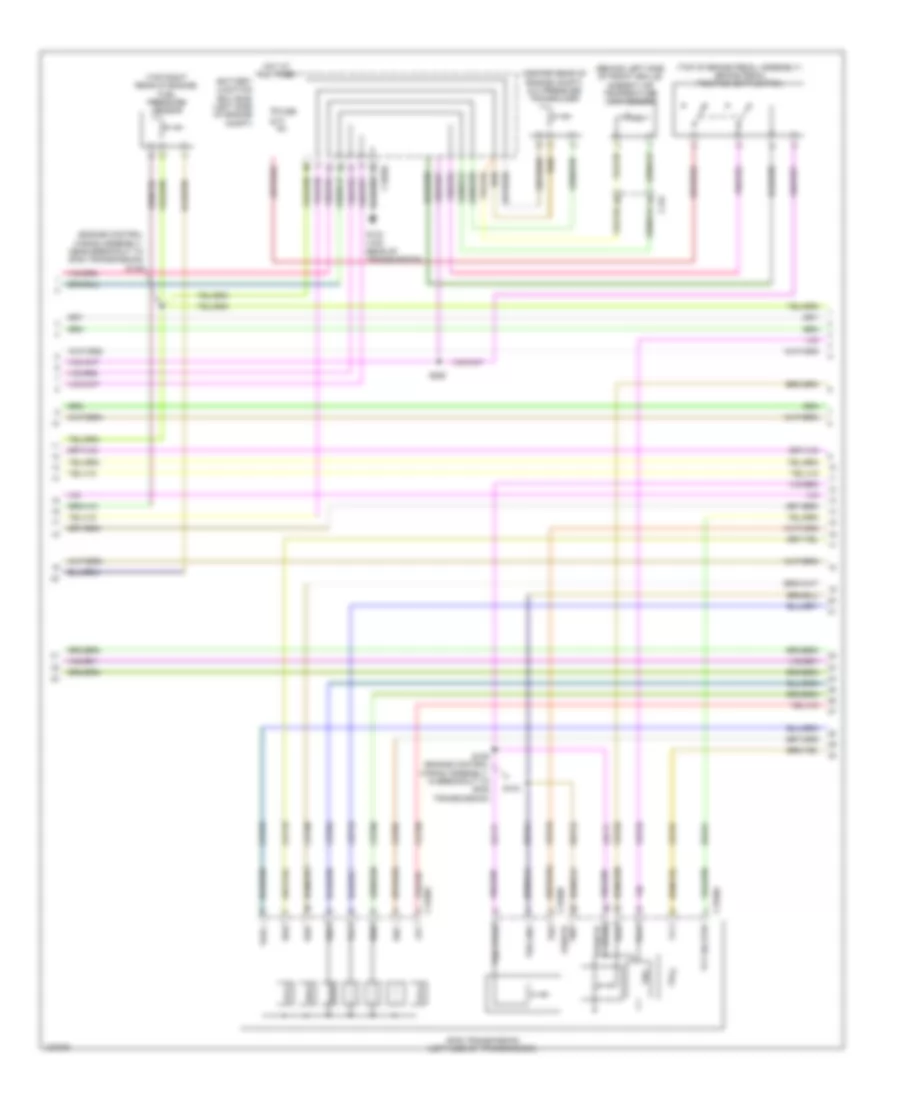
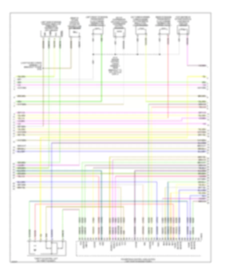
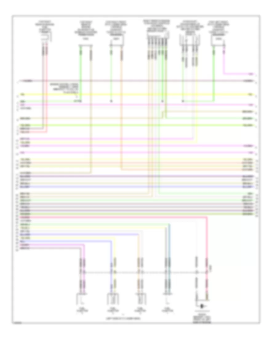
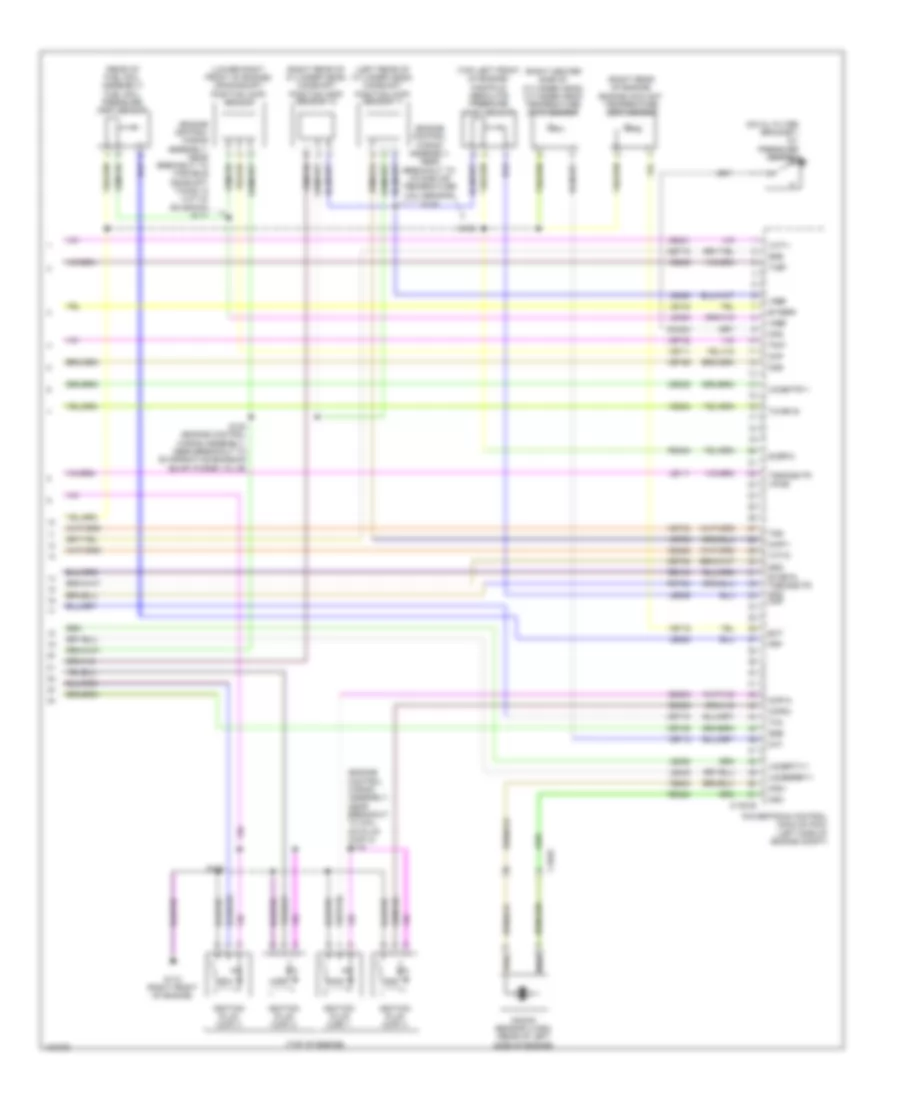
2.5L, Engine Performance Wiring Diagram (1 of 5) for Ford Escape S 2014
List of elements for 2.5L, Engine Performance Wiring Diagram (1 of 5) for Ford Escape S 2014:
- (junction box wiring assembly, near breakout to bjb) s146
- A/c pressure transducer (center rear of engine compt)
- Aat
- Accr
- Acpt
- Air conditioning system
- App1
- App2
- Apprtn 1
- Apprtn2
- Appvref1
- Appvref2
- Battery junction box (bjb) (left side of engine compt)
- Bpp
- Bps
- C-vref
- C1035c
- C175b
- C210
- C212
- C3053
- Canv
- Cbb08
- Cbk01
- Ccb08
- Cdc12
- Cdc34
- Cdc35
- Cdc54
- Ce114
- Ce302
- Ce436
- Ce515
- Ces09
- Cet42
- Cet43
- Ch302
- Computer data lines system
- Cooling fans system
- Early production
- Fpc
- Fpm
- Ftp
- Fuel tank pressure (ftp) sensor (on evap emission canister assembly)
- Fuse 10a
- Fuse 15a
- Fuse 30a
- Fuse 5a
- G104 (top rear of transmission)
- Gd120
- Hot at all times
- Hs can+
- Hs can-
- Iat
- Isp-r
- Late production
- Le136
- Le137
- Le230
- Le424
- Lfc
- Lin
- Maf
- Mafrtn
- Nca sst gnd
- Nca sst+
- Nca sst-
- Pcm power relay
- Pcm wake
- Pcmrc
- Power distribution system
- Power gnd
- Powertrain control module (pcm) (left side of engine compt)
- Pwr gnd
- Re136
- Re137
- Re320
- Re407
- Rh107
- S112 (engine control wiring assembly, in breakout to powertrain control module (pcm))
- S147
- Sigrtnc
- Smc
- Smcs
- Smr
- Sst+
- Sst-
- Starting/ charging system
- Starting/charging system
- Transmission control switch (base of shift lever assembly)
- Vdb04
- Vdb05
- Vdn06
- Ve203
- Ve225
- Ve701
- Ve702
- Ve740
- Ve750
- Ve807
- Ve922
- Vh433
- Vpwr
- Vref
2.5L, Engine Performance Wiring Diagram (2 of 5) for Ford Escape S 2014
List of elements for 2.5L, Engine Performance Wiring Diagram (2 of 5) for Ford Escape S 2014:
- (behind right end of front grille) active grille shutter
- (near breakout to powertrain control
- (top of accelerator pedal assembly) accelerator pedal position (app) sensor
- (top of brake pedal assembly) brake pedal position (bpp) switch
- 6f35 transmission (left side of transmission)
- Ambient air temperature (aat) snsor (behind left side of front grille)
- Battery junction box (bjb) (left side of engine compt)
- C1035c
- C134
- C1520a
- C1520b
- Cet05
- Cet06
- Cet07
- Cet08
- Cet09
- Cet10
- Cet18
- Cet25
- Digital
- Fuse 5a
- Hot at all times
- Hot in start or run
- Le111
- Lpc
- Manifold absolute pressure (map) sensor & temperature (left rear of engine)
- Module (pcm))
- Oss
- Oss/tr gnd
- Oss/tr vpwr
- Re406
- Ret24
- S101
- S102
- S250
- Ssa
- Ssb
- Ssc
- Ssd
- Sse
- Tcc
- Tft
- Tft sig rtn
- Trp
- Trs
- Tspc
- Tss
- Tss gnd
- Tss vpwr
- Vet26
- Vet27
- Vet32
- Vet33
- Vref 5v
2.5L, Engine Performance Wiring Diagram (3 of 5) for Ford Escape S 2014
List of elements for 2.5L, Engine Performance Wiring Diagram (3 of 5) for Ford Escape S 2014:
- (engine control wiring assembly, near breakout to c145) s121
- (front of cylinder head) knock sensor 1 (ks1)
- (left rear of engine) manifold absolute pressure (map) sensor
- (not used)
- (top rear of transmission) g104
- (top right side of fuel tank) fuel pump (fp) assembly
- (under right rear of vehicle) evaporative emission (evap) canister vent valve
- (under right rear seat) fuel pump driver module
- Battery junction box (bjb) (left side of engine compt)
- C1035c
- C175t
- C210
- C3053
- C3063
- Cbp56
- Ce233
- Ce515
- Cet05
- Cet06
- Cet07
- Cet08
- Cet09
- Cet10
- Cet18
- Cet25
- Cet34
- Early production
- Fpc
- Fpm
- Fppwr
- Fprtn
- Fuse 10a
- G301 (base of right "c" pillar)
- Gd152
- Gnd
- Heated oxygen sensor (ho2s) 12 (in exhaust, downstream of catalytic converter)
- Ho2s12
- Htr12
- Late production
- Le111
- Lpc
- Nca
- Oss
- Powertrain control module (pcm) (left side of engine compt)
- Re406
- Re515
- Ret24
- S203 (body wiring assembly, near breakout to g200)
- Sigrtn
- Ssa
- Ssb
- Ssc
- Ssd
- Sse
- Tcc
- Tcs
- Tft
- Tr-p
- Tspc
- Tss
- Tss/oss tr vpwr
- Tss/oss/tr gnd
- Ve225
- Ve518
- Ve731
- Vet26
- Vet27
- Vet32
- Vet33
- Vper fuel
2.5L, Engine Performance Wiring Diagram (4 of 5) for Ford Escape S 2014
List of elements for 2.5L, Engine Performance Wiring Diagram (4 of 5) for Ford Escape S 2014:
- (engine control wiring assembly, near breakout to fuel injector 3) s113
- (right center side of cylinder bank) cylinder head temperature (cht) sensor
- (top left rear of engine) evaporative emission (evap) purge valve
- (top of engine)
- (top rear of engine) exhaust gas regulation (egr) vacuum regulator solenoid
- Body control module (bcm) (bottom right side of dash)
- C2280a
- C2280b
- C2280e
- Ccb08
- Ce436
- Coil
- Computer data lines system
- Fuel pump relay
- Fuel sndr rtn
- Fuel sndr sig
- Fuse 20a
- Hot at all times
- Ignition plug (cop) 1
- Ignition plug (cop) 2
- Ignition plug (cop) 3
- Ignition plug (cop) 4
- Micro
- Ms can+
- Ms can-
- Noise suppression capacitor (top of engine)
- Pcm wake up suply
- Rmc32
- S176 (engine control wiring assembly, near breakout to ignition transformer capacitor 1)
- Stop light sw
- Throttle control unit (on throttle body)
- Transmission fluid warmer temperature control valve 1 (rear of engine)
- Transmission fluid warmer temperature control valve 2 (left front of engine)
- Vdb06
- Vdb07
- Vmc11
2.5L, Engine Performance Wiring Diagram (5 of 5) for Ford Escape S 2014
List of elements for 2.5L, Engine Performance Wiring Diagram (5 of 5) for Ford Escape S 2014:
- (top center of cylinder bank) camshaft position (cmp11) sensor 11
- (top of engine) fuel injectors
- C175e
- Cdv 1
- Cdv 2
- Ce101
- Ce102
- Ce103
- Ce104
- Ce113
- Ce171
- Ce172
- Ce205
- Ce206
- Ce207
- Ce208
- Ce235
- Ce303
- Ce304
- Ce305
- Ce306
- Ce412
- Ce422
- Ce426
- Cht
- Cmc24
- Cmp1
- Computer data lines system
- Cop1a
- Cop2d
- Cop3b
- Cop4c
- Cpk+
- Cpk-
- Crankshaft position (ckp) sensor (lower right front of engine)
- De135
- Egrmc1
- Egrmc2
- Egrmc3
- Egrmc4
- Etcref
- Etcrtn
- Evapcp
- Inj1
- Inj2
- Inj3
- Inj4
- Instrument panel cluster (ipc) module
- Ks1+
- Ks1-
- Le111
- Le134
- Le423
- Le448
- Le451
- Le452
- Map
- Ms can+
- Ms can-
- Oil pressure switch (on oil filter bracket)
- Ops
- Powertrain control module (pcm) (left side of engine compt)
- Re134
- Re135
- Re323
- Re405
- S100 (engine control wiring assembly, near breakout to ignition transformer capacitor 1)
- Shdrtn
- Sigrtne
- Tacm+
- Tacm-
- Tp1
- Tp2
- Universal heated oxygen sensor (ho2s) 11 (right rear of engine, in exhaust manifold)
- Uo2s11
- Uo2sgref11
- Uo2shtr
- Uo2spc11
- Uo2spct 11
- Variable camshaft timing (vct11) solenoid 11 (top left front of cylinder head)
- Vct11
- Ve706
- Ve711
- Ve712
- Ve801
- Ve803
- Ve818
- Ve819
- Ve826
- Vref
EXTERIOR LIGHTS
Backup Lamps Wiring Diagram for Ford Escape S 2014
List of elements for Backup Lamps Wiring Diagram for Ford Escape S 2014:
- (not used)
- (right "d" pillar) g400
- (tailgate wiring assembly near breakout to c438) s415
- 1.6l turbo
- 2.0l turbo
- 2.5l
- 6f35 transmission (left side of transmission)
- Auto dimming interior mirror
- Body control module (bcm) (bottom right center of dash)
- C1381b
- C1381e
- C1520a
- C1551b
- C1551e
- C175b
- C215
- C2280c
- C2280e
- C2280f
- C410
- C438
- Computer data lines system
- Fuse 10a
- Hot at all times
- Hs can+
- Hs can-
- Le111 (or let57)
- Left reversing lamp
- Micro
- Powertrain control module (pcm) (left side of engine compt)
- Ret24
- Rev
- Reversing lamp relay
- Right reversing lamp
- S104 (2.0l turbo) s130 (1.6l turbo) s102 (2.5l) (2.0l turbo: engine control wiring assembly, in breakout to 6f35 transmission) (1.6l turbo: engine control sensor extension wiring assembly, near breakout to g104) (2.5l: engine control wiring assembly, near breakout to powertrain control module (pcm))
- S106 (2.0l turbo) s101 (2.5l) (2.0l turbo: engine control wiring assembly, in breakout to 6f35 transmission) (2.5l: engine control wiring assembly, near breakout to powertrain control module (pcm))
- S132 (1.6l turbo) (engine control sensor extension wiring assembly, near breakout to c1019)
- S414
- Tr vpwr
- Tr-p
- Tr-p tss/ oss/ tr gnd c175t
- Transmissions system
- Tss/ oss/
- Tss/ oss/tr gnd
- Tss/ oss/tr vpwr
- Vdb04
- Vdb05
- Vet32
Exterior Lamps Wiring Diagram (1 of 2) for Ford Escape S 2014
List of elements for Exterior Lamps Wiring Diagram (1 of 2) for Ford Escape S 2014:
- (in steering column) steering column control module (sccm)
- (junction box wiring assembly, near breakout to g103) s133
- (left front of engine compt)
- (left kick panel) g205
- (or cls45)
- 1.6l turbo
- 2.0l turbo
- 2.5l
- Adaptive front lighting module (upper right side of dash)
- Battery junction box (bjb) (left side of engine compt)
- Body control module (bcm) (bottom right center of dash)
- Bpp
- Bps
- Brake pedal position (bpp) switch (top of brake pedal assembly)
- C1021a
- C1021b
- C1035c
- C1041a
- C1041b
- C1284b
- C1285b
- C134
- C1381b
- C1551b
- C175b
- C212
- C226a
- C2280a
- C2280b
- C2280c
- C2280d
- C2280g
- C410
- C934
- Ccb08
- Ces09
- Chmsl
- Clf06
- Clf07
- Cls04
- Cls06
- Cls07
- Cls17
- Cls21
- Cls23
- Cls25
- Cls27
- Cls32
- Cls44
- Cls45
- Computer data lines system
- Cornering
- Cornering left
- Cornering right
- Early production
- Front controls interface module (fcim)
- Fuse 15a
- Fuse 5a
- G103 (right side of engine compt)
- G104 (top rear of transmission)
- G107
- G107 (left front of engine compt)
- G205 (left kick panel)
- G206 (right kick panel)
- G400 (right "d" pillar)
- Gd133
- Gd138
- Gnd
- Hazard
- Headlamp switch
- Hot at all times
- Hot in start or run
- Hs can +
- Hs can -
- Hs can+
- Hs can-
- Late production
- Left headlamp assembly
- Left side turn signal lamp
- Left stop lp
- Lf park lt
- Lin
- Lin 1
- Lr park lt
- Micro
- Ms can+
- Ms can-
- Multi-function switch
- Park
- Powertrain control module (pcm) (left side of engine compt)
- Pwr gnd
- Red
- Rf park lt
- Right headlamp assembly
- Right rear park/stop turn lamp
- Right side turn signal lamp
- Rr park lt
- S125 (1.6l turbo)
- S134
- S136 (junction box wiring assembly, near breakout to right front windshield wiper motor)
- S148
- S159
- S221
- S241
- S250
- S400
- Sbb17
- Side marker
- Side mirr rt stop lp
- Side mirr turn ind lr turn
- Start/run
- Stop
- Stop lt sw
- Turn
- Turn ind
- Vbatt
- Vdb04
- Vdb05
- Vdb06
- Vdb07
- Vlf25
- Vmc34
- Vpwr
- W/ hid
- W/o hid
Exterior Lamps Wiring Diagram (2 of 2) for Ford Escape S 2014
List of elements for Exterior Lamps Wiring Diagram (2 of 2) for Ford Escape S 2014:
- (in license plate jumper (pia)) s420
- (park aid sensor wiring assembly, near breakout to knock sensor 1 (ks1)) (w/ halogen & w/o fog lamps) s177
- (park aid sensor wiring assembly, near breakout to left front parking lamp) (w/ halogen & w/o fog lamps) s156
- A14
- C1445
- C1446
- C151
- C161
- C1617d
- C339
- C340
- C421
- C422
- C431
- C438
- C501a
- C501b
- C652a
- C652b
- C934
- Cls22
- Cls26
- Computer data lines system
- Driver door module (ddm)
- Fuse 4 25a
- Fuse 5 25a
- Fuse 50a
- G107 (left front of engine compt)
- G201 (under front passenger's door sill)
- G203 (under driver's door sill)
- G400 (right "d" pillar)
- G401 (left "d" pillar)
- Gd134
- Gd140
- Gnd
- High current battery junction box (bjb) (left side of engine compt)
- High mounted stoplamp
- Hot at all times
- Instrument panel cluster (ipc) module
- Left exterior mirror
- Left license plate lamp
- Left parking lamp
- Left parking lamp (w/ halogen & w/o fog lamps)
- Left rear park/stop turn lamp
- Mirr gnd
- Ms can +
- Ms can -
- Ms can+
- Ms can-
- Nca
- Park
- Passenger door module (pdm)
- Rear junction box (rjb) (behind right quarterpanel)
- Red
- Right exterior mirror
- Right license plate lamp
- Right parking lamp
- Right parking lamp (w/ halogen & w/o fog lamps)
- Rpmo5
- Rpmo8
- S159
- S323 (w/ trailer tow early productin) (body wiring assembly, near breakout to restraints control module (rcm))
- S402
- S414
- S421
- S500
- S600
- Sbr04
- Sbr05
- Stop
- Trailer/camper adapter circuit
- Turn
- Turn lp vpwr
- Vbatt
- Vdb06
- Vdb07
- W/ rear view camera
- W/o rear view camera
Trailer/Camper Adapter Wiring Diagram, Early Production for Ford Escape S 2014
List of elements for Trailer/Camper Adapter Wiring Diagram, Early Production for Ford Escape S 2014:
- (body wiring assembly, near cls44
- Body control module (bcm) (bottom right center of dash)
- Brake sig
- Brake signal
- Breakout to restraints control module (rcm)) s323
- C2280a
- C2280b
- C432
- C4397a
- C4397b
- C4397c
- Cat06
- Cat09
- Cat11
- Cls44
- Computer data lines system
- Exterior lamps circuit
- Fuse 40a
- G400 (right "d" pillar)
- Gd152
- Gnd
- Hot at all times
- Left turn
- Micro
- Ms can +
- Ms can -
- Ms can+
- Ms can-
- Park
- Rear junction box (rjb) (behind right quarterpanel)
- Right turn
- S400
- Sbr11
- Trailer module (right "d" pillar)
- Trailer socket (under left center of rear bumper)
- Vdb06
- Vdb07
- Vpwr
Trailer/Camper Adapter Wiring Diagram, Late Production for Ford Escape S 2014
List of elements for Trailer/Camper Adapter Wiring Diagram, Late Production for Ford Escape S 2014:
- C432
- C4397a
- C4397b
- C4397c
- Cat06
- Cat09
- Cat11
- Computer data lines system
- Fuse 40a
- G400 (right "d" pillar)
- Gd152
- Gnd
- Hot at all times
- Left turn
- Ms can +
- Ms can -
- Park
- Rear junction box (rjb) (behind right quarterpanel)
- Right turn
- S400
- Sbr11
- Trailer module (right "d" pillar)
- Trailer socket (under left center of rear bumper)
- Vdb06
- Vdb07
- Vpwr
GROUND DISTRIBUTION
Ground Distribution Wiring Diagram (1 of 4) for Ford Escape S 2014
List of elements for Ground Distribution Wiring Diagram (1 of 4) for Ford Escape S 2014:
- (2.0l & 1.6l) ignition coil on plug 1
- (2.0l & 1.6l) ignition coil on plug 2
- (2.0l & 1.6l) ignition coil on plug 3
- (2.0l & 1.6l) ignition coil on plug 4
- (2.5l) air conditioning compressor (except 2.5l) air conditioning clutch & air conditioning clutch field coil
- (canada) front fog relay
- (junction box wiring assembly, near breakout to g103) s134
- (left side of engine compt) battery junction box (bjb)
- (w/ perimeter alarm) hood switch
- 1.6l
- 2.0l
- 2.5l
- 2.5l & 2.0l
- Active grille shutter
- Anti-lock brake system (abs) module
- Battery
- Battery junction box (bjb) (left side of engine compt)
- Battery monitoring sensor
- Body control module (bcm)
- Brake pedal position (bpp) switch
- C1021a
- C1021b
- C1035c
- C1041a
- C1041b
- C1284a
- C1284b
- C1285a
- C1285b
- C134
- C1381b
- C1463a
- C1551b
- C175b
- C2280a
- C2603b
- Cooling fan motor
- Electric booster heater
- Engine cooling fan relay
- Filling operation
- G100 (left rear of engine compt)
- G103 (right side of engine compt)
- G104 (top rear of transmission)
- G105 (left rear of engine compt)
- G106 (right rear of engine compt)
- G107 (left front of engine compt)
- G108 (left rear of engine compt)
- G109 (left rear of engine compt)
- G110 (2.0l) (right front of engine)
- G111 (1.6l) (left rear of engine)
- G112 (left rear of engine compt)
- Horn
- Left front fog lamp
- Left front windshield wiper motor
- Left headlamp assembly
- Left parking lamp
- Left side turn signal lamp
- Low brake fluid warning indicator switch
- Power steering control module (pscm)
- Powertrain control module (pcm)
- Right front fog lamp
- Right front windshield wiper motor
- Right headlamp assembly
- Right parking lamp
- Right side turn signal lamp
- S125 (engine control sensor extension wiring assembly, near breakout to c1019)
- S137 (junction box wiring assembly, near breakout to brake fluid level switch)
- S159 (park aid sensor wiring assembly, near breakout to left front inner parking aid sensor)
- S174 (2.0l) s126 (1.6l) (2.0l: engine control wiring assembly, near breakout to coil on plug (cop) 2) (1.6l: engine control sensor extension wiring assembly, near breakout to g111)
- W/ halogen lamps
- W/ hid lamps
- W/ intelligent access
Ground Distribution Wiring Diagram (2 of 4) for Ford Escape S 2014
List of elements for Ground Distribution Wiring Diagram (2 of 4) for Ford Escape S 2014:
- (automatic a/c) electronic automatic temperature control (eatc) module
- (front passenger's door wiring assembly, near breakout to front passenger's door side impact sensor)
- (if equipped) left front heated seat switch
- (if equipped) right front heated seat switch
- (manual a/c) heating ventilation & air conditioning (hvac) control module
- (manual a/c) in-vehicle temperature/ humidity sensor
- (w/ 4.2 inch display & base audio) front control/ display interface module (fcdim)
- (w/ ambient lighting) right front interior door handle ambient lighting lamp
- (w/ door modules) driver door module (ddm)
- (w/ door modules) passenger door module (pdm)
- (w/ memory) driver seat module (dsm)
- (w/ memory) driver side front seat control switch
- (w/ sync) accessory protocol interface module (apim)
- (w/o door modules) driver door window control switch
- (w/o door modules) left front door latch release motor
- (w/o door modules) passenger door window control switch
- (w/o door modules) right front door latch release motor
- (w/o memory) driver side front seat control switch
- Audio unit
- B11
- Body control module (bcm)
- C214
- C217b
- C218a
- C218b
- C226a
- C2280e
- C228b
- C2357a
- C2366
- C2367
- C240a
- C260
- C2998
- C2999
- C311
- C312
- C327
- C329a
- C339
- C340
- C341d
- C359a
- C421
- C431
- C501a
- C504b
- C504c
- C652a
- C934
- Clock spring
- Control switch)
- Data link connector
- Front controls interface module (fcim)
- G200 (under front passenger's door sill)
- G201 (under front passenger's door sill)
- G203 (under driver's door sill)
- G204 (left kick panel)
- G205 (left kick panel)
- Headlamp switch
- Horn switch
- Instrument panel ambient lighting lamp
- Instrument panel cluster (ipc) module
- Instrument panel console switch assembly
- Keyless entry keypad
- Left front door lock switch
- Left front heated seat module
- Left front interior door handle ambient lighting lamp (w/ ambient lighting)
- Left steering wheel multi-function switch
- Nca
- Parking brake switch
- Passenger air bag deactivation (pad) indicator/ defrost switch
- Rear parking aid camera
- Right front door lock switch
- Right front heated seat module
- Right steering wheel multi-function switch
- S211 (main wiring assembly, near breakout to panel/ floor mode door actuator)
- S236 (steering wheel harness, near breakout to c260)
- S310 (w/ memory) (body wiring assembly, near breakout to c311)
- S327
- S500 (driver's door wiring assembly, near breakout to driver's front door side impact sensor)
- Steering column control module (sccm)
- Transmission control switch (tcs)
- W/ 4.2 inch display
- W/ 8 inch display
- W/ memory
- W/o memory
Ground Distribution Wiring Diagram (3 of 4) for Ford Escape S 2014
List of elements for Ground Distribution Wiring Diagram (3 of 4) for Ford Escape S 2014:
- (automatic a/c) blower motor control module
- (except base w/o dc/ac converter) rear passenger power outlet socket
- (manual a/c) heating ventilation & air conditioning (hvac) control module
- (w/ 110v power inverter) dc/ac inverter module
- (w/ ambient lighting) floor console cup holder ambient lighting lamp
- (w/ ambient lighting) left footwell lamp
- (w/ ambient lighting) rear footwell lamp
- (w/ ambient lighting) right footwell lamp
- (w/ door modules) left rear door module
- (w/ door modules) right rear door module
- (w/ intelligent access) radio frequency (rf) receiver
- (w/ intelligent access) remote function actuator (rfa) module
- (w/ roof opening panel) left front interior lamp
- (w/ roof opening panel) left rear interior lamp
- (w/ roof opening panel) right front interior lamp
- (w/ roof opening panel) right rear interior lamp
- (w/o door modules) left rear door latch release motor
- (w/o door modules) left rear door window control switch
- (w/o door modules) right rear door latch release motor
- (w/o door modules) right rear door window control switch
- A11 c313
- A11 c314
- Adaptive front lighting module
- Auto- dimming interior mirror
- Auxiliary power point
- Breakout to c313)
- C215
- C2357b
- C248
- C297a
- C328
- C3501
- C4392c
- Front interior lamp
- Front power outlet socket
- Fuel pump (fp) assembly shield
- Fuel pump driver module (fpdm)
- G206 (right kick panel)
- G300 (under driver's door sill)
- G301 (base of right "c" pillar)
- G302 (under front passenger's door sill)
- Global positioning system module (gpsm)
- Glove compartment lamp
- Left vanity mirror lamp
- Nca
- Overhead console
- Rain sensor
- Rear interior lamp
- Right vanity mirror lamp
- Roof opening panel module
- S241 (main wiring assembly, near breakout to headlamp control module (hcm))
- S301 (body wiring assembly, near breakout to right hand second row side impact sensor)
- S329 (center console wiring assembly, near breakout to c3501)
- S900 (interior lamp wiring assembly, near breakout to auto-dimming interior mirror)
- S904
- W/ sunvisor illumination
- W/o sunvisor illumination
Ground Distribution Wiring Diagram (4 of 4) for Ford Escape S 2014
List of elements for Ground Distribution Wiring Diagram (4 of 4) for Ford Escape S 2014:
- (early production) image processing module b (ipm-b)
- (if equipped) trailer module
- (if equipped) trailer socket
- (late production) luggage compartment power outlet socket
- (w/ intelligent access) hands free actuation module
- (w/ power liftgate) power liftgate switch
- (w/o power liftgate) liftgate/ luggage compartment lid latch
- Auto digital signal processing (dsp) module
- C410
- C4174a
- C421
- C422
- C431
- C432
- C4326c
- C438
- C4397b
- C4464
- C934
- Early production
- Four-wheel drive (4wd) control module
- G101 (left front of engine compt)
- G102 (rear of engine)
- G400 (right "d" pillar)
- G401 (left "d" pillar)
- High mounted stop lamp
- Late production
- Left license plate lamp
- Left rear lamp assembly
- Left rear park/ stop/ turn lamp
- Left reversing lamp
- Left side obstacle detection control module
- Liftgate/ luggage compartment lid release switch
- Nca
- Parking aid module (pam)
- Rear gate/ trunk module (rgtm)
- Rear heated window element
- Rear window wiper motor
- Right license plate lamp
- Right rear lamp assembly
- Right rear park/ stop/ turn lamp
- Right reversing lamp
- Right side obstacle detection control module
- S400 (body wiring assembly, near breakout to g400)
- S402 (body wiring assembly, near breakout to g401)
- S414 (tailgate wiring assembly near breakout to c438)
- S418 (body wiring assembly, in breakout to audio digital signal processing (dsp) module)
- S421 (in license plate jumper (pia))
- W/ rearview camera
- W/ trailer tow
- W/o rearview camera
- W/o trailer tow
HEADLIGHTS
Headlights Wiring Diagram, with High Intensity Gas Discharge Headlights (1 of 2) for Ford Escape S 2014
List of elements for Headlights Wiring Diagram, with High Intensity Gas Discharge Headlights (1 of 2) for Ford Escape S 2014:
- (right kick
- Adaptive front lighting module (upper right side of dash)
- Battery junction box (bjb) (left side of engine compt)
- C1021a
- C1041a
- C212
- Cbb39
- Cbb43
- Clf06
- Clf07
- Computer data
- Computer data lines system
- Drl
- Exterior
- Exterior lights system
- Fuse 15a
- Fuse 5a
- G103 (right side of engine compt)
- G107 (left front of engine compt)
- G206
- Gd138
- Hid
- High
- High beam
- Hot w/ ignition relay energized
- Hs can +
- Hs can -
- Instrument panel cluster (ipc)
- Left headlamp assembly
- Lights system
- Lines system
- Lt cornering
- Ms can +
- Ms can -
- Panel)
- Park
- Pwr gnd
- Right headlamp assembly
- Rt cornering
- S134
- S135 (junction box wiring assembly, in breakout to right headlamp assembly)
- S140
- S148
- S150 (junction box wiring assembly, in breakout to left headlamp assembly)
- S241
- Start/run
- Vbatt
- Vdb04
- Vdb05
Headlights Wiring Diagram, with High Intensity Gas Discharge Headlights (2 of 2) for Ford Escape S 2014
List of elements for Headlights Wiring Diagram, with High Intensity Gas Discharge Headlights (2 of 2) for Ford Escape S 2014:
- Air conditioning system
- Autolamp/rain sensor (top center of dash)
- Autolamp/sunload sensor (top center of dash)
- Autolamps sensor
- Automatic a/c
- Battery junction box (bjb) (left side of engine compt)
- Body control module (bottom right center of dash)
- C134
- C212
- C213
- C226a
- C2280c
- C2280d
- C237
- Canada
- Clf04
- Clf05
- Clf29
- Clf34
- Cmc25
- Computer data lines system
- Evap temp sensor
- Evaporator temperature sensor (left side of hvac evaporator assembly)
- Fog lamp relay (usa)
- Front fog lamp relay (canada)
- Fuse 15a
- Fuse 5a
- G107 (left front of engine compt)
- G205 (left kick panel)
- Gnd
- Headlamp switch
- High beam relay
- Hot at all times
- Hot w/ ignition relay energized
- Hs can +
- Hs can -
- Left front fog lamp
- Lin
- Lin 1
- Manual a/c
- Micro
- Multi-function switch
- Parking brake switch (base of parking brake lever assembly)
- Prk brake
- Right front fog lamp
- Rlf14
- S148
- S159
- S160
- S221
- Sigrtn
- Steering column control module (sccm) (in steering column)
- Usa
- Vbatt
- Vdb04
- Vdb05
- Vh406
- Vlf14
- Vlf25
- Vmc34
- Vpwr
Headlights Wiring Diagram, without High Intensity Gas Discharge Headlights (1 of 2) for Ford Escape S 2014
List of elements for Headlights Wiring Diagram, without High Intensity Gas Discharge Headlights (1 of 2) for Ford Escape S 2014:
- (right kick
- Adaptive front lighting module (upper right side of dash)
- Battery junction box (bjb) (left side of engine compt)
- C1284a
- C1285a
- C212
- C226a
- Cbb39
- Cbb43
- Clf06
- Clf07
- Computer data
- Computer data lines system
- Exterior
- Fuse 15a
- Fuse 5a
- G103 (right side of engine compt)
- G107 (left front of engine compt)
- G206
- Gd138
- High
- Hot w/ ignition relay energized
- Hs can +
- Hs can -
- Instrument panel cluster (ipc) module
- Left headlamp assembly
- Lights system
- Lin 1
- Lines system
- Low
- Lt cornering
- Ms can +
- Ms can -
- Multi-function switch
- Panel)
- Pwr gnd
- Right headlamp assembly
- Rt cornering
- S134
- S140
- S148
- S241
- Start/run
- Steering column control module (sccm) (in steering column)
- Vbatt
- Vdb04
- Vdb05
- Vmc34
Headlights Wiring Diagram, without High Intensity Gas Discharge Headlights (2 of 2) for Ford Escape S 2014
List of elements for Headlights Wiring Diagram, without High Intensity Gas Discharge Headlights (2 of 2) for Ford Escape S 2014:
- Air conditioning system
- Autolamp/rain sensor (top center of dash)
- Autolamp/sunload sensor (top center of dash)
- Autolamps sensor
- Automatic a/c
- Battery junction box (bjb) (left side of engine compt)
- Body control module (bottom right center of dash)
- C134
- C212
- C213
- C2280c
- C2280d
- C237
- Clf04
- Clf05
- Cmc25
- Computer data lines system
- Evap temp sensor
- Evaporator temperature sensor (left side of hvac evaporator assembly)
- Fog lamp relay
- Fuse 15a
- Fuse 5a
- G107 (left front of engine compt)
- G205 (left kick panel)
- Gnd
- Headlamp switch
- High beam relay
- Hot at all times
- Hs can +
- Hs can -
- Left front fog lamp
- Left headlamp low beam
- Lin
- Lin 1
- Manual a/c
- Micro
- Parking brake switch (base of parking brake lever assembly)
- Prk brake
- Right front fog lamp
- Right headlamp low beam
- Rlf14
- S159
- S221
- Sigrtn
- Vbatt
- Vdb04
- Vdb05
- Vh406
- Vlf14
- Vlf25
- Vmc34
HORN
Horn Wiring Diagram for Ford Escape S 2014
List of elements for Horn Wiring Diagram for Ford Escape S 2014:
- (left side of engine compt) battery junction box (bjb)
- 15a
- Body control module (bcm) (bottom right center of dash)
- C1617d
- C1617j
- C217a
- C217b
- C218a
- C218b
- C2280a
- C2280c
- C2280g
- C260
- Clockspring (steering column)
- Crh03
- Crh04
- Fuse
- Fuse 5a
- G103 (right side of engine compt)
- G205 (left kick panel)
- Ground distribution system
- High current battery junction box (bjb) (left side of engine compt)
- Horn
- Horn (right front of engine compt)
- Horn rc
- Horn relay
- Horn switch (top of steering column)
- Hot at all times
- Logic gnd
- Mega fuse 4 50a
- Mega fuse 9 50a
- Micro
- Red
- S134
- S144
- S221
- S235
- S236
- Sbb17
- Sbb18
- Vbatt
INSTRUMENT CLUSTER
Instrument Cluster Wiring Diagram (1 of 2) for Ford Escape S 2014
List of elements for Instrument Cluster Wiring Diagram (1 of 2) for Ford Escape S 2014:
- (steering wheel harness, near breakout to c260) s242
- (w/o intelligent access) ignition switch
- 4.2 inch display
- 8 inch display
- Body control module (bcm) (bottom right center of dash)
- C218b
- C218c
- C226a
- C226b
- C2280a
- C2280b
- C2280c
- C2280e
- C2280f
- C2280g
- C260
- C4174a
- C4174b
- C431
- C934
- Cdc30
- Cet52
- Clockspring (steering column)
- Cmc19
- Cmc25
- Cmc29
- Computer data lines system
- Cpl26
- Cpl31
- Cpl36
- Cpl39
- Cpl44
- Cpl81
- Disp signal
- Disp trip gnd
- Down
- Fp lvl gnd
- Fp lvl sensor
- Fuel pump (fp) assembly (top right side of fuel tank)
- Fuse 5a
- G103 (right side of engine compt)
- G200 (under front passenger's door sill)
- G205 (left kick panel)
- G400 (right "d" pillar)
- Gd138
- Gd140
- Gd150
- Gnd
- Gnd pwr
- Hot at all times
- Hs can+
- Hs can-
- I can +
- I can -
- Instrument panel cluster (ipc)
- Interior lights system
- Key in ign sw
- Key in ignition
- Left
- Left steering wheel multi-function switch (4.2 inch display)
- Lf door ajar
- Liftgate ajar
- Liftgate/luggage compartment lid latch (left center of liftgate)
- Low brake fluid warning indicator switch (on brake fluid reservoir)
- Lr door ajar
- Lvl sw brk fluid
- Micro
- Ms can +
- Ms can -
- Ms can+
- Ms can-
- Nca
- Park brake
- Parking brake switch (base of parking brake lever assembly)
- Prk detect sw
- Rear gate trunk module (rtm) (lower left side of liftgate)
- Red
- Rf door ajar
- Right
- Right steering wheel multi-function switch (4.2 inch display)
- Rmc27
- Rmc32
- Rr door ajar
- S134
- S221
- S414
- Sbb17
- Sbb18
- Sbp08
- Shift interlock system
- Sound systems
- Steering column control module (in steering column)
- Trip sig
- V batt
- Vbatt
- Vdb04
- Vdb06
- Vdb07
- Vdb13
- Vdb14
- Vdbo5
- Vdbo7
- Vmc11
- Vmc29
- W/ power liftgate
- W/o power liftgate
Instrument Cluster Wiring Diagram (2 of 2) for Ford Escape S 2014
List of elements for Instrument Cluster Wiring Diagram (2 of 2) for Ford Escape S 2014:
- (or cmc24)
- 1.6l turbo
- 2.0l turbo
- 2.0l turbo & 1.6l turbo
- 2.5l
- A11
- C1381b
- C1381e
- C1551b
- C1551e
- C175b
- C175e
- C313
- C314
- C339
- C340
- C501a
- C501b
- C652a
- C652b
- Ce908
- Computer data lines system
- Driver door module (ddm)
- G201 (under front passenger's door sill)
- G203 (under driver's door sill)
- G300 (under driver's door sill)
- G302 (under front passenger's door sill)
- Gd134
- Gd140
- Gd143
- Gd145
- Gnd
- Ground distribution system
- High current battery junction box (bjb) (left side of engine compt)
- Hot at all times
- Hs can +
- Hs can -
- Left front door latch release motor
- Left rear door latch release motor
- Left rear door module
- Mega fuse 50a
- Ms can +
- Ms can -
- Oil pressure switch (1.6l turbo: left side of engine) (2.0l turbo: on oil filter bracket
- Oil pressure switch (on oil filter bracket)
- Ops
- Passenger door module (ddm)
- Power windows system
- Powertrain control module (pcm) (left side of engine compt)
- Red
- Right front door latch release motor
- Right rear door latch release motor
- Right rear door module
- Rpl63
- Rpl64
- Rpw07
- Rpw09
- Rtn
- S500
- S600
- S700
- S701 (rear door wiring assembly, near breakout to left rear power window motor)
- S800
- S801 (rear door wiring assembly, near breakout to c823)
- Vdb04
- Vdb05
- Vdb06
- Vdb07
- W/ door modules
- W/o door modules
INTERIOR LIGHTS
Courtesy Lamps Wiring Diagram (1 of 3) for Ford Escape S 2014
List of elements for Courtesy Lamps Wiring Diagram (1 of 3) for Ford Escape S 2014:
- (interior lamp wiring assembly, near breakout to overhead console switch assembly)
- Body control module (bcm) (bottom right center of dash)
- C1617d
- C1617j
- C214
- C215
- C2280a
- C2280b
- C2280c
- C2280e
- C2280f
- C2280g
- C2280h
- C339
- Cln33
- Computer data lines system
- Courtesy
- Cpl26
- Cpl31
- Cpl36
- Cpl39
- Cpl44
- Dimming rtn
- Driver door window control switch
- Fuse 10a
- G103 (right side of engine compt)
- G200 (under front passenger's door sill)
- G206 (right kick panel)
- Gd123
- Gd140
- Glove compartment lamp
- High current battery junction box (bjb) (left side of engine compt)
- Hot at all times
- Hs can +
- Hs can -
- Instrument illumination circuit
- Interior light relay
- Lamp control
- Left footwell lamp (w/0 ambient lighting)
- Left front interior lamp (w/ roof opening panel)
- Left rear interior lamp (w/ roof opening panel)
- Left vanity mirror lamp
- Lf door ajar
- Liftgate ajar
- Lin 2
- Logic gnd
- Lr door ajar
- Luggage compartment lamp
- Map
- Mega fuse 4 50a
- Mega fuse 9 50a
- Micro
- On/off
- Pwr gnd
- Red
- Rf door ajar
- Right footwell lamp (w/0 ambient lighting)
- Right front interior lamp (w/ roof opening panel)
- Right vanity mirror lamp
- Rr door ajar
- S206 (body wiring assembly, near breakout to g200)
- S238 (main wiring assembly, near breakout to glove box lamp)
- S241
- S244 (steering wheel harness, near breakout to c260)
- S900
- S903 (interior lamp wiring assembly, near breakout to overhead console switch assembly)
- Sbb17
- Sbb18
- Vbatt
- Vdb04
- Vdb05
- Vln30
- Vln33
- Vpwr
- W/ door modules
- W/ roof opening panel
- W/o roof opening panel
Courtesy Lamps Wiring Diagram (2 of 3) for Ford Escape S 2014
List of elements for Courtesy Lamps Wiring Diagram (2 of 3) for Ford Escape S 2014:
- (rear door wiring assembly, near breakout to c823) s801
- (rear door wiring assembly, near breakout to left rear power window motor)
- A11
- Base
- C215
- C313
- C314
- C339
- C340
- C4174a
- C4174b
- C431
- C501a
- C501b
- C652a
- C652b
- C934
- Cls01
- Cls02
- Computer data lines system
- Courtesy
- Cpl81
- Driver door module (ddm)
- Early production
- Except base
- Front interior lamp (w/o roof opening panel)
- G201 (under front passenger's door sill)
- G203 (under driver's door sill)
- G206 (right kick panel)
- G300 (under driver's door sill)
- G302 (under front passenger's door sill)
- G400 (right "d" pillar)
- Gd134
- Gd140
- Gd143
- Gd145
- Gd150
- Gnd
- Ground distribution system
- Instrument illumination circuit
- Lamp control
- Late production
- Left exterior mirror
- Left front door latch release motor
- Left rear door latch release motor
- Left rear door module
- Liftgate ajar
- Liftgate latch
- Map
- Mirr gnd
- Ms can +
- Ms can -
- Nca
- Passenger door module (ddm)
- Pdl lp
- Power windows system
- Rear gate trunk module (rgtm) (lower left side of liftgate)
- Rear interior lamp (early production)
- Rear interior lamp (late production)
- Right front door latch release motor
- Right rear door latch release motor
- Right rear door module
- Right rear interior lamp (w/ roof opening panel)
- Roof lamp control
- Rpl63
- Rpl64
- Rpm05
- Rpm08
- Rpw07
- Rpw09
- Rtn
- S241
- S414
- S500
- S700
- S701
- S900
- S904 (w/o sunvisor illumination)
- Vdb06
- Vdb07
- W/ door modules
- W/ power liftgate
- W/o door modules
- W/o power liftgate
Courtesy Lamps Wiring Diagram (3 of 3) for Ford Escape S 2014
List of elements for Courtesy Lamps Wiring Diagram (3 of 3) for Ford Escape S 2014:
- (steering wheel harness, near breakout to c260) s242
- B10
- B12
- C214
- C215
- C327
- C339
- C340
- Ecu
- Floor console cup holder ambient lighting lamp
- G201 (under front passenger's door sill)
- G203 (under driver's door sill)
- G206 (right kick panel)
- Instrument illumination circuit
- Led
- Left
- Left footwell lamp
- Left interior front door handle ambient lighting lamp
- Lin
- Lin 2
- Map pocket
- Nca
- Overhead console (w/ ambient lighting)
- Rear footwell lamp
- Release handle
- Right
- Right exterior mirror
- Right footwell lamp
- Right interior front door handle ambient lighting lamp
- S241
- S243 (steering wheel harness, near breakout to clockspring)
- S329
- S339
- S340
- S500
- S600
- S900
- Vpwr
Instrument Illumination Wiring Diagram for Ford Escape S 2014
List of elements for Instrument Illumination Wiring Diagram for Ford Escape S 2014:
- (body wiring assembly, near breakout to g201) s205
- (left kick panel) g205
- (main wiring assembly, near breakout to right floor discharge air temperature sensor) s232
- (steering column) clockspring
- A10
- B13
- Battery junction box (bjb) (left side of engine compt)
- Body control module (bcm) (bottom right center of dash)
- C1617d
- C1617j
- C212
- C215
- C218a
- C218b
- C218c
- C226a
- C226b
- C2280a
- C2280b
- C2280c
- C2280e
- C2280g
- C2280h
- C260
- C327
- C339
- C340
- Computer data lines system
- Cpk28
- Cpk36
- Front interior lamp
- Fuse 5a
- G103 (right side of engine compt)
- G200 (under front passenger's door sill)
- G201 (under front passenger's door sill)
- G203 (under driver's door sill)
- G205 (left kick panel)
- G206 (right kick panel)
- Gd123
- Gd140
- Gnd
- Headlamp switch
- High current battery junction box (bjb) (left side of engine compt)
- Hot at all times
- Hs can +
- Hs can -
- Ignition switch (w/ intelligent access)
- Illum
- Instrument panel console switch assembly
- Ip sw illum
- Keyless entry keypad
- Keypad illum
- Left front door lock switch
- Left front heated seat switch
- Left front interior lamp
- Left lower steering wheel switch
- Left upper steering wheel switch
- Lin
- Logic gnd
- Mega fuse 4 50a
- Mega fuse 9 50a
- Micro
- Nca
- Overhead console
- Passenger airbag deactivation (pad) indicator/ defrost switch
- Pwr gnd
- Red
- Right front door lock switch
- Right front heated seat switch
- Right lower steering wheel switch
- Right upper steering wheel switch
- S221
- S235
- S236
- S241
- S243 (steering wheel harness, near breakout to clockspring)
- S244 (steering wheel harness, near breakout to c260)
- S327
- S328
- S500
- S600
- S900
- S904
- Sbb17
- Sbb18
- Steering column control module (sccm) (in steering column)
- Sw illum
- Switch assembly)
- Transmission illum control switch (tcs) (base of shift lever assembly)
- Vbatt
- Vdb04
- Vdb05
- Vlf25
- Vln04
- W/ memory
- W/ sony sound
- W/o memory
- W/o roof opening panel &
- W/o roof opening panel & w/ sunvisor illumination
- W/o sony sound
- W/o sunvisor illumination
MEMORY SYSTEMS
Driver"s Memory Seat Wiring Diagram (1 of 2) for Ford Escape S 2014
List of elements for Driver"s Memory Seat Wiring Diagram (1 of 2) for Ford Escape S 2014:
- (not used)
- (not used) c311
- Aft
- B15
- B16
- B17
- C311
- C339
- C341a
- C341b
- C341d
- Cbx03
- Cbx05
- Computer data lines system
- Cps14
- Cps15
- Cps16
- Cps17
- Cps23
- Cps24
- Cps25
- Cps26
- Cps27
- Cps28
- Cps29
- Cps30
- Cps55
- Cps64
- Cps65
- Deflate
- Driver seat module (dsm) (under driver's seat)
- Driver side door lock control switch
- Forward
- Front dn
- Front up
- Fuse 25a
- Fuse 5a
- G203 (under driver's door sill)
- Gd903
- Gd906
- Hall effect return
- Hall effect sense
- Hot at all times
- Incline
- Inflate
- Logic gnd
- Mem set +
- Mem set -
- Memory set switch
- Ms can +
- Ms can -
- Pwr gnd
- Rear dn
- Rear junction box (rjb) (behind right quarterpanel)
- Rear up
- Recline
- Rps12
- Rps13
- Rps14
- S330
- S331
- S333
- S500
- Set 1
- Set 2
- Set 3
- Set ind
- Vbatt
- Vdb06
- Vdb07
- Vps10
- Vps11
- Vps12
- Vsp09
Driver"s Memory Seat Wiring Diagram (2 of 2) for Ford Escape S 2014
List of elements for Driver"s Memory Seat Wiring Diagram (2 of 2) for Ford Escape S 2014:
- (left cushion power equipment wiring assembly, in breakout to driver's seat front height motor) s334
- (left cushion power equipment wiring assembly, in breakout to driver's seat module (dsm)) s332
- (under driver's door sill) g203
- Aft
- Base backward
- Base forward
- C3309
- C341c
- Cps01
- Cps02
- Cps03
- Cps04
- Cps05
- Cps06
- Cps07
- Cps08
- Cps18
- Cps19
- Deflate
- Driver seat front height motor
- Driver seat module (dsm) (under driver's seat)
- Driver seat rear height motor
- Driver side front seat control switch
- Front down
- Front seat recliner motor
- Front seat track motor
- Front up
- Fwd
- Height front
- Height rear
- Horizontal
- Incline
- Inflate
- Lumbar
- Lumbar motor
- Rear down
- Rear up
- Recline
- S331
Memory Mirrors Wiring Diagram (1 of 2) for Ford Escape S 2014
List of elements for Memory Mirrors Wiring Diagram (1 of 2) for Ford Escape S 2014:
- (not used)
- (not used) c311
- B15
- B16
- B17
- Blis led feed
- Blis ret
- C311
- C339
- C341b
- C341d
- C501a
- C501b
- Cbx03
- Cbx05
- Cls01
- Cls22
- Computer data lines system
- Cpm03
- Cpm28
- Cpm29
- Cps14
- Cps15
- Cps16
- Cps17
- Cps55
- Crb06
- Crd13
- Driver door module (ddm)
- Driver seat module (dsm) (under driver's seat)
- Drv mirr horz pot
- Drv mirr mtr dn/lt
- Drv mirr mtr horz rt
- Drv mirr mtr vert up
- Drv mirr vert pot
- Ext mrr pot feed
- G203 (under driver's door sill)
- Gd134
- Gd903
- Gd906
- Gnd
- L/r
- Left exterior mirror
- Left exterior mirror blind spot (blis)/ cross traffic alert (cta) led
- Left front door lock control switch
- Logic gnd
- Lpm30
- Mem set +
- Mem set -
- Memory set switch
- Mirr htr
- Mirr pot ret
- Mirr ret
- Ms can +
- Ms can -
- Nca
- Puddle
- Puddle lmp
- Pwr gnd
- Rpm05
- Rpm30
- Rps14
- Rrb06
- S330
- S331
- S333
- S500
- S501 (driver's door wiring assembly, in breakout to c521)
- Sbr04
- Set 1
- Set 2
- Set 3
- Set ind
- Side turn
- Turn
- U/d
- Vbatt
- Vdb06
- Vdb07
- Vpm35
- Vpm36
Memory Mirrors Wiring Diagram (2 of 2) for Ford Escape S 2014
List of elements for Memory Mirrors Wiring Diagram (2 of 2) for Ford Escape S 2014:
- A14
- Blis led feed
- Blis ret
- C339
- C340
- C652a
- C652b
- Cls02
- Cls26
- Computer data lines system
- Cpm06
- Cpm33
- Cpm34
- Crb07
- Crd14
- Ext mrr pot feed
- Fuse 25a
- Fuse 5a
- G201 (under front passenger's door sill)
- Gd140
- Gnd
- Hot at all times
- L/r
- Lpm12
- Mirr htr
- Mirr pot ret
- Mirr ret
- Ms can +
- Ms can -
- Nca
- Pass mirr horz pot
- Pass mirr mtr dn/lt
- Pass mirr mtr horz rt
- Pass mirr mtr vert up
- Pass mirr vert pot
- Passenger door module (pdm)
- Puddle
- Puddle lmp
- Rear junction box (rjb) (behind right quarterpanel)
- Right exterior mirror
- Right exterior mirror blind spot (blis)/ cross traffic alert (cta) led
- Rpm08
- Rpm12
- Rrb07
- S600
- S601 (front passenger's door wiring assembly, in breakout to right exterior rear view mirror)
- Sbr05
- Side turn
- Turn
- U/d
- Vbatt
- Vdb06
- Vdb07
- Vpm37
- Vpm38
NAVIGATION
Blind Spot Information System Wiring Diagram for Ford Escape S 2014
List of elements for Blind Spot Information System Wiring Diagram for Ford Escape S 2014:
- (or cbr29)
- A14
- Bislert
- C339
- C340
- C501a
- C501b
- C652a
- C652b
- Cbr11
- Computer data lines system
- Crb06
- Crb07
- Driver door module (ddm)
- Fuse 25a
- Fuse 5a
- G201 (under front passenger's door sill)
- G203 (under driver's door sill)
- G400 (right "d" pillar)
- G401 (left "d" pillar)
- Gd134
- Gd140
- Gd150
- Gd152
- Gnd
- Hot at all times
- Hot w/ accessory relay energized
- Left exterior mirror
- Left exterior mirror blind spot (blis)/ cross traffic alert (cta) led
- Left side obstacle detection control module (sod-l) (base of left "d" pillar)
- Ms can+
- Ms can-
- Msx can+
- Msx can-
- Nca
- Nsx can+
- Nsx can-
- Passenger door module (pdm)
- Rear junction box (rjb) (behind right quarterpanel)
- Return
- Right exterior mirror
- Right exterior mirror blind spot (blis)/ cross traffic alert (cta) led
- Right side obstacle detection module (sod-r) (base of right "d" pillar)
- Rrb06
- Rrb07
- S400
- S402
- S403
- S500
- S600
- Sbr04
- Sbr05
- Start/run
- Vbatt
- Vdb06
- Vdb07
Parking Assistant Wiring Diagram for Ford Escape S 2014
List of elements for Parking Assistant Wiring Diagram for Ford Escape S 2014:
- (behind right quarterpanel) parking aid module (pam)
- (park aid sensor wiring assembly, near breakout to left front inner parking aid sensor) s157
- (rear park aid sensor wiring assembly, near breakout to rear inner left parking aid sensor) s417
- C134
- C210
- C214
- C3053
- C4014a
- C4014b
- C4014c
- C432
- Cbr01
- Cmp02
- Cmp18
- Cmp31
- Cmp32
- Computer data lines system
- Early production
- Fil sens in
- Fir sens in
- Fol sens in
- For sens in
- Fuse 5a
- G205 (left kick panel)
- G400 (right "d" pillar)
- Gd152
- Gnd
- Hot w/ accessory relay energized
- Hs can +
- Hs can -
- Instrument panel console switch assembly
- Interior lights system
- Late production
- Left front active park assist sensor (left corner of front bumper fascia)
- Left front inner parking aid sensor (behind left end of front bumper)
- Left front outer parking aid sensor (behind left end of front bumper)
- Left rear inner parking aid sensor (behind left side of rear bumper)
- Left rear outer parking aid sensor (behind left end of rear bumper)
- Lf sens in
- Lmp06
- Lmp07
- Pass
- Rear junction box (rjb) (behind right quarterpanel)
- Rf sens in
- Right front active park assist sensor (behind right corner of front bumper fascia)
- Right front inner parking aid sensor (behind right side of front bumper)
- Right front outer parking aid sensor (behind right end of front bumper)
- Right rear inner parking aid sensor (behind right side of rear bumper)
- Right rear outer parking aid sensor (behind right end of rear bumper)
- Ril sens in
- Rir sens in
- Rmp06
- Rmp07
- Rol sens in
- Ror sens in
- S158 (park aid sensor wiring assembly, near breakout to left front inner parking aid sensor)
- S221
- S400
- S416 (rear park aid sensor wiring assembly, near breakout to rear inner left parking aid sensor)
- Sapp
- Sens gnd
- Sens pwr
- Solid state
- Status led pas
- Status led sapp
- Sw pas
- Sw sapp
- Vdb04
- Vdb05
- Vmp10
- Vmp11
- Vmp12
- Vmp13
- Vmp14
- Vmp15
- Vmp16
- Vmp17
- Vmp21
- Vpm20
- Vpwr
Rear Camera Wiring Diagram, Early Production for Ford Escape S 2014
List of elements for Rear Camera Wiring Diagram, Early Production for Ford Escape S 2014:
- Accessory protocol interface module (under center console)
- C214
- C421
- C431
- C934
- Cbr99
- Cmp10
- Computer data lines system
- Fuse 5a
- G204 (left kick panel)
- G401 (left "d" pillar)
- Gd152
- Gnd
- Hot w/ accessory relay energized
- Image processing module b (ipm-b)
- Lin
- Ms can +
- Ms can -
- Nca
- Pwr
- Rear junction box (rjb) (behind right quarterpanel)
- Rear parking aid camera (right center of liftgate)
- Rmp31
- S211
- S402
- S403
- Shield
- Vdb06
- Vdb07
- Video+
- Video-
- Vmp31
- Vmp35
- Vpwr
Rear Camera Wiring Diagram, Late Production for Ford Escape S 2014
List of elements for Rear Camera Wiring Diagram, Late Production for Ford Escape S 2014:
- (bottom right center of dash) body control module (bcm)
- Accessory protocol interface module (apim) (w/ sync) front control/ display interface module (fcdim) (w/o sync) (accessory protocol interface module: under center console)
- C214
- C2280a
- C3053
- C410
- C421
- C431
- C438
- C934
- Fuse 5a
- G204 (left kick panel)
- Gnd
- Hot w/ accessory relay energized
- Lin
- Lin2 (rcv lin 2)
- Nca
- Pwr
- Rear junction box (rjb) (behind right quarterpanel)
- Rear parking aid camera (right center of liftgate)
- Rmp31
- S211
- S403 (w/ blis)
- Shield
- Video+
- Video-
- Vmp31
- W/ sync
- W/o sync
POWER DISTRIBUTION
Power Distribution Wiring Diagram (1 of 6) for Ford Escape S 2014
List of elements for Power Distribution Wiring Diagram (1 of 6) for Ford Escape S 2014:
- (2.0l: engine control wiring assembly, near breakout to coil on plug (cop) 2) (1.6l: engine control sensor extension wiring assembly, near breakout to coil on plug (cop) 2)
- (diagram 3 of 6)
- (diagram 4 of 6)
- (engine control wiring assembly, near breakout to fuel (2.0l) s116 (1.6l) s122
- (junction box wiring assembly, in breakout to bjb) s144
- (left side of engine compt) battery junction box (bjb)
- (left side of engine compt) high current battery junction box (bjb)
- (right kick panel) g206
- 1.6l
- 2.0l
- 2.5l
- A/c clutch relay
- Anti-lock brake system (abs) module
- Auxiliary power point
- Battery
- Battery junction box (bjb) (left side of engine compt)
- Battery monitoring sensor
- Blower motor relay
- Body control module (bcm) (bottom right center of dash)
- Body control module (bcm) (early production)
- Brake pedal position (bpp) switch
- C1035a
- C1035b
- C1035c
- C1381b
- C1463a
- C1551b
- C1617a
- C1617b
- C1617c
- C1617d
- C1617e
- C1617f
- C1617g
- C1617h
- C1617j
- C1617l
- C175b
- C197a
- C210
- C211
- C212
- C219
- C22800
- C2280g
- C2603a
- C3053
- C328
- C339
- Early
- Electric booster heater
- Engine cooling fan relay
- Evaporative emission canister vent solenoid (2.5l)
- Except 2.0l
- Except 2.5l
- Front power outlet socket
- Fuel pump relay
- Fuse 10a
- Fuse 15a
- Fuse 20a
- Fuse 30a
- Fuse 40a
- Fuse 5a
- G100 (left rear of engine compt)
- Generator
- Headlamp switch
- Horn relay
- Ignition coil on-plugs
- Injector 3) (2.5l) s113
- Keyless entry keypad
- Late production
- Liftgate/ decklid release relay
- Mega fuse 1 80a
- Mega fuse 2 150a
- Mega fuse 3 100a
- Mega fuse 4 50a
- Mega fuse 6 70a
- Mega fuse 60a
- Mega fuse 8 50a
- Mega fuse 80a
- Mega fuse 9 50a
- Micro
- Noise suppression capacitor (2.5l)
- Pcm power relay
- Power steering control module (pscm)
- Powertrain control module (pcm)
- Production
- Rear passenger power outlet socket
- Rear window defrost relay
- Red
- Red (battery cable wiring assembly, near breakout to generator) s155
- S131 (1.6l) s103 (2.0l) s112 (2.5l) (1.6l: engine control sensor extension wiring assembly, near breakout to c1019) (2.0l: engine control wiring assembly, in breakout to battery junction box (bjb)) (2.5l: engine control wiring assembly, in breakout to powertrain control module (pcm))
- S151 (power steering wiring assembly, near breakout to g108)
- S329
- Starter motor
- Starter relay
- To battery junction box (bjb) (diagram 2 of 6)
- To battery junction box (bjb) (diagram 6 of 6)
- To fuse 33 (diagram 2 of 6)
- To fuse 70
- To fuse 74
- To rear junction box (rjb) (diagram 5 of 6)
- To splice s401 (diagram 5 of 6)
- V batt
Power Distribution Wiring Diagram (2 of 6) for Ford Escape S 2014
List of elements for Power Distribution Wiring Diagram (2 of 6) for Ford Escape S 2014:
- (2.0l: engine control wiring assembly, near breakout to coil on plug (cop) 4) (2.5l: engine control wiring assembly, near breakout to ignition transformer capacitor 1) (2.0l) s119 (2.5l) s100
- (canada) front fog relay
- (engine control sensor extension wiring assembly, near breakout to engine coolant temperature (ect) sensor) (1.6l) s128
- (junction box wiring assembly, in breakout to battery junction box)
- (junction box wiring assembly, near breakout to g105) s140
- (left side of engine compt) battery junction box (bjb)
- (not used)
- 1.6l
- 2.0l
- 2.5l
- A/c clutch relay
- A13
- Active grille shutter
- Adaptive front lighting module
- Air conditioning (a/c) compressor control solenoid (except 2.5l)
- Anti-lock brake system (abs) module
- Auxiliary windshield wiper motor
- Body control module (bcm) (bottom right center of dash)
- C1021a
- C1035c
- C1041a
- C133
- C1381b
- C1463b
- C1551b
- C175b
- C210
- C212
- C2280d
- C3053
- C312
- C339
- C410
- C438
- C504a
- Control relay ignition
- Coolant bypass valve (1.6l)
- Driver door window control switch (w/o door modules)
- Early production
- Engine cooling fan relay
- Evaporative emission (evap) canister vent valve (except 2.5l)
- Evaporative emission canister purge valve
- Exhaust camshaft (vct) oil solenoid (1.6l)
- Four wheel drive (4wd) control module (except 2.5l)
- From fuse 35 g (diagram 1 of 6)
- From splice s144 (diagram 1 of 6)
- From splice s145 (diagram 1 of 6)
- Fuse 10a
- Fuse 15a
- Fuse 20a
- Fuse 50a
- Fuse 5a
- Heated oxygen sensor (ho2s) 12
- Ignition relay
- Late production
- Left headlamp assembly
- Micro
- Nca
- Near breakout to brake fluid level switch)
- Occupant classification system module (ocsm)
- Passenger air bag deactivation (pad) indicator/ defrost switch
- Power steering control module (pscm)
- Powertrain control module (pcm)
- Rear window wiper motor
- Right headlamp assembly
- S143
- S147 (junction box wiring assembly, near breakout to battery junction box)
- To body control module (bcm) (diagram 3 of 6)
- To heated oxygen sensor (ho2s) 11 variable timing control (diagram 6 of 6)
- Trans- mission fluid warmer temperature control valve 1
- Transmission fluid warmer tempera- ture control valve 2
- Turbocharger (tc) wastegate regulating valve solenoid (2.0l)
- Variable camshaft timing (vct) solenoid 11 (2.0l)
- Variable camshaft timing (vct) solenoid 12 (2.0l)
- Wastegate control solenoid (1.6l)
- Wastegate control valve (1.6l)
- Wastegate position sensor (except 2.5l)
- Windshield wiper motor
Power Distribution Wiring Diagram (3 of 6) for Ford Escape S 2014
List of elements for Power Distribution Wiring Diagram (3 of 6) for Ford Escape S 2014:
- (body wiring assembly, near breakout to c311) s314
- (body wiring assembly, near breakout to g200) s206
- (bottom right center of dash) body control module (bcm)
- (main wiring assembly, near breakout to panel/ floor mode door actuator) s214
- (main wiring assembly, near breakout to start/stop switch) s218
- (not used)
- (steering wheel harness, near breakout to c260) s244
- (steering wheel harness, near breakout to clockspring) s235
- Accessory protocol interface module (apim)
- All lock relay
- Audio unit
- Auto- dimming interior mirror
- Automatic a/c
- C214
- C215
- C226a
- C2280d
- C2280e
- C2280f
- C2280h
- C228b
- C2357a
- C240a
- C248
- C2603c
- C310a
- C311
- C312
- C327
- C329a
- C339
- C359a
- Data link connector (dlc)
- Driver door unlock relay
- Driver door window control switch
- Electric booster heater
- Electronic automatic temperature (eatc) module
- From battery junction box (bjb) (diagram 2 of 6)
- From fuse 65 c (diagram 1 of 6)
- Front control/ display interface module (fcdim) (4.2 inch display)
- Front controls interface module (fcim)
- Fuse 10a
- Fuse 15a
- Fuse 20a
- Fuse 25a
- Fuse 5a
- Fuse 7.5a
- Global position- ing system module (gpsm)
- Glove compart- ment lamp
- Heating ventilation & air conditioning (hvac) control module
- In-vehicle temperature/ sensor
- Instrument panel cluster (ipc)
- Interior light relay
- Left footwell lamp (w/o ambient lighting)
- Left front heated seat module
- Left front seat heated switch
- Luggage compart- ment lamp
- Manual a/c
- Micro
- Passenger door unlock relay
- Passive anti-theft transceiver
- Radio frequency (rf) receiver (w/ intelligent access)
- Rain sensor
- Restraints control module (rcm)
- Right footwell lamp (w/o ambient lighting)
- Right front heated seat module
- Right front seat heated switch
- Roof opening panel module
- S328
- Spare relay
- Steering column control module (sccm)
- To splice s901 (diagram 6 of 6)
- W/ door modules
- W/ heated seats
Power Distribution Wiring Diagram (4 of 6) for Ford Escape S 2014
List of elements for Power Distribution Wiring Diagram (4 of 6) for Ford Escape S 2014:
- 1.6l
- 2.0l
- 2.5l
- Acc
- Acc run
- Acc/ run
- Battery junction box (bjb) (left side of engine compt)
- Body control module (bcm) (bottom right center of dash)
- C1035c
- C1381b
- C1551b
- C175b
- C212
- C214
- C2280c
- C2280f
- C4392d
- Fog lamp relay
- From fuse 56 b (diagram 1 of 6)
- Front washer relay
- Fuse 10a
- Fuse 15a
- Fuse 20a
- Fuse 5a
- High beam relay
- Ignition switch
- Illum
- Instrument panel cluster (ipc)
- Key in ign sw
- Key in ignition switch
- Lock
- Micro
- Nca
- Off
- Powertrain control module (pcm)
- Rear washer relay
- Remote function actuator (rfa) module
- Reversing lamp relay
- Run
- S254
- Start
- Start/ run
- Start/ stop sw 1
- Start/ stop sw 2
- Start/stop switch
- Transmission control switch (tcs)
- W/ intelligent access
- W/o intelligent access
Power Distribution Wiring Diagram (5 of 6) for Ford Escape S 2014
List of elements for Power Distribution Wiring Diagram (5 of 6) for Ford Escape S 2014:
- (behind right quarterpanel) rear junction box (rjb)
- (body wiring assembly, near breakout to audio digital signal processing (dsp) module) s419
- (body wiring assembly, near breakout to c312) s311
- (body wiring assembly, near breakout to rjb) s403
- (left cushion power equipment wiring assembly, in breakout to driver's seat module (dsm))
- (not used)
- A14
- A17
- Ac outlet
- Acc
- Accessory relay
- Audio digital signal processing (dsp) module
- Body control module (bcm) (bottom right center of dash)
- C214
- C2280b
- C311
- C312
- C313
- C314
- C327
- C328
- C329a
- C339
- C340
- C341d
- C3497a
- C359a
- C4014a
- C410
- C4174a
- C421
- C432
- C4326c
- C438
- C4392c
- C4397a
- C4464
- C501a
- C511
- C611
- C652a
- C710
- C810
- Control relay accessory
- Dc/ac current inverter (under center console)
- Driver door module (ddm)
- Driver seat module (dsm) (w/ memory)
- Driver side front seat control switch
- Early production
- Early production & late production
- From high current battery junction box (bjb) (diagram 1 of 6)
- Fuse 10a
- Fuse 20a
- Fuse 25a
- Fuse 30a
- Fuse 40a
- Fuse 5a
- G206 (right kick panel)
- G400 (right "d" pillar)
- Gnd
- Handsfree actuation module
- Image processing module (ipm-b)
- Late production
- Left front exterior door handle
- Left front heated seat module
- Left rear door module
- Left rear exterior door handle (early production)
- Left side obstacle detection control module (sodl)
- Luggage compartment power outlet socket (late production)
- Micro
- Nca
- Parking aid module (pam)
- Passenger door module (pdm)
- Rear gate trunk module (rgtm)
- Rear parking aid camera (late production)
- Red
- Remote function actuator (rfa) module
- Right front exterior door handle
- Right front heated seat module
- Right rear door module
- Right rear exterior door handle (early production)
- Right side obstacle detection control module (sodr)
- S329
- S330
- S400
- S401 (body wiring assembly, near breakout to rjb)
- Trailer module
- W/ memory
- W/ trailer tow
- W/o memory
- W/o trailer tow
Power Distribution Wiring Diagram (6 of 6) for Ford Escape S 2014
List of elements for Power Distribution Wiring Diagram (6 of 6) for Ford Escape S 2014:
- (interior lamp wiring assembly, near breakout to overhead console switch assembly) s901
- (left side of engine compt) battery junction box (bjb)
- 2.5l
- A11
- A14
- Accessory
- Accessory delay relay
- Body control module (bcm) (bottom right center of dash)
- C210
- C2280a
- C3053
- C339
- C340
- C504b
- C504c
- Control delay relay
- Driver door window control switch (w/o door modules)
- Early production
- Except 2.5l
- Exhaust gas recirculation vacuum regulator solenoid (2.5l)
- From m splice s100 (diagram 2 of 6)
- From splice s144 (diagram 1 of 6)
- From splice s145 (diagram 1 of 6)
- From splice s244 j (diagram 3 of 6)
- Front interior lamp (w/o roof opening panel)
- Fuse 25a
- Heated oxygen sensor (ho2s) 11 variable timing control
- Intake variable camshaft timing (vct) oil control solenoid (1.6l)
- Late production
- Left front interior lamp assembly (w/ roof opening panel)
- Left rear interior lamp (w/ roof opening panel)
- Left vanity mirror lamp
- Manifold absolute pressure & temperature (mapt) sensor (2.5l)
- Micro
- Overhead console (w/ ambient lighting)
- Passenger door window control switch (w/o door modules)
- Rear interior lamp (w/o roof opening panel)
- Right front interior lamp (w/ roof opening panel)
- Right rear interior lamp (w/ roof opening panel)
- Right vanity mirror lamp
- S181
- S300 (body wiring assembly, near breakout to c340a)
- Variable camshaft timing (vct) oil control solenoid (2.5l)
POWER DOOR LOCKS
Power Door Locks Wiring Diagram, with Intelligent Access (1 of 5) for Ford Escape S 2014
List of elements for Power Door Locks Wiring Diagram, with Intelligent Access (1 of 5) for Ford Escape S 2014:
- (body wiring assembly, near breakout to c211) s200
- (body wiring assembly, near breakout to g201) s204
- (left center of liftgate) (w/o power liftgate) liftgate/luggage compartment lid latch
- (lower left side of liftgate) rear gate trunk module
- (right "d" pillar) g400
- A11
- A12
- A13
- Ajar
- Body control module (bcm) (bottom right center of dash)
- C214
- C2280a
- C2280b
- C2280c
- C2280h
- C313
- C339
- C340
- C4174a
- C4174b
- C431
- C934
- Ccd15
- Cls32
- Computer data lines system
- Cpl04
- Cpl25
- Cpl26
- Cpl30
- Cpl31
- Cpl35
- Cpl36
- Cpl38
- Cpl39
- Cpl41
- Cpl42
- Cpl43
- Cpl44
- Cpl53
- Cpl81
- Cpl87
- Crh04
- Dr lock cntrl sw ind (led)
- Dr unlock
- Front controls interface module (fcim)
- G103 (right side of engine compt)
- G107 (left front of engine compt)
- G201 (under front passenger's door sill)
- G203 (under driver's door sill)
- G205 (left kick panel)
- G300 (under driver's door sill)
- G400 (right "d" pillar)
- Gd123
- Gd133
- Gd134
- Gd150
- Gnd
- Hazard warning signal switch/
- Hood ajar sw
- Hood switch (w/ perimeter alarm) (center front of engine compt)
- Horn rly ctrl
- Horns system
- Illum
- Interior lights system
- K-line
- Left front door lock switch
- Left rear door latch release motor
- Left rear door module (rdm)
- Lf dr ajar
- Lf dr unlock
- Liftgate ajar
- Lin
- Lock
- Logic gnd
- Lr dr ajar
- Lr dr unlock
- Mem p1
- Mem p2
- Mem p3
- Memory systems
- Micro
- Ms can+
- Ms can-
- Nca
- Power windows system
- Red
- Return
- Rf dr ajar
- Rf dr unlock
- Right front door lock switch
- Rpw07
- Rr dr ajar
- Rr dr unlock
- S148
- S221
- S414
- S500
- S600
- S700
- S701 (rear door wiring assembly, near breakout to left rear power window motor)
- Sbp06
- Sbr06
- Sbr25
- Sig sw/hazard warning
- Switch indicator (led) door lock control
- Unlock
- Vbatt
- Vdb06
- Vdb07
- Vpl56
- Vpw32
- Vrt22
- W/ door modules
- W/ memory
- W/ power liftgate
- W/o door modules
- W/o memory
- W/o power liftgate
Power Door Locks Wiring Diagram, with Intelligent Access (2 of 5) for Ford Escape S 2014
List of elements for Power Door Locks Wiring Diagram, with Intelligent Access (2 of 5) for Ford Escape S 2014:
- (rear door wiring assembly, near breakout to c823) s801
- (under front passenger's door sill) g302
- A11
- A12
- A13
- A14
- A16
- A17
- Ajar
- B12
- C313
- C314
- C339
- C340
- C410
- C438
- C652a
- C652b
- Computer data lines system
- Cpl05
- Cpl35
- Cpl41
- Cpl54
- Cpl65
- Cpl66
- Dr unlock
- Fuse 25a
- G201 (under front passenger's door sill)
- G302 (under front passenger's door sill)
- Gd140
- Gnd
- Ground distribution system
- Hot at all times
- Lin
- Lock
- Ms can+
- Ms can-
- Passenger door module (pdm)
- Power windows system
- Rear junction box (rjb) (behind right quarterpanel)
- Red
- Return
- Right front door latch release motor
- Right rear door latch release motor
- Right rear door module
- Rpl64
- Rpw09
- S318 (body wiring assembly, near breakout to c312)
- S319 (body wiring assembly, near breakout to restraints c314 control module (rcm))
- S600
- S800
- Sbr05
- Sbr07
- Unlock
- Vbatt
- Vdb06
- Vdb07
- Vpw33
- W/ door modules
- W/o door modules
Power Door Locks Wiring Diagram, with Intelligent Access (3 of 5) for Ford Escape S 2014
List of elements for Power Door Locks Wiring Diagram, with Intelligent Access (3 of 5) for Ford Escape S 2014:
- (not used)
- A12
- A16
- Ajar
- All lock relay
- B12
- Body control module (bcm) (bottom right center of dash)
- C2280e
- C2280f
- C339
- C431
- C501a
- C501b
- C934
- Computer data lines system
- Cpl02
- Cpl30
- Cpl51
- Cpl75
- Cpl76
- Cpl84
- Dr unlock
- Driver door module (ddm)
- Driver door unlock relay
- Driver door window control switch (w/ door modules)
- Fuse 10a
- Fuse 15a
- Fuse 20a
- G203 (under driver's door sill)
- Gd134
- Gnd
- Hot at all times
- Left front door latch
- Liftgate decklid release relay
- Lin
- Lock
- Micro
- Ms can+
- Ms can-
- Passenger door unlock relay
- Return
- Rpl63
- S235
- S500
- S502 (driver's door wiring assembly, near breakout to driver side power window motor)
- Sbr04
- Unlock
- Vbatt
- Vdb06
- Vdb07
- Vpw32
- W/ door modules
- W/ power liftgate
- W/o door modules
- W/o power liftgate
Power Door Locks Wiring Diagram, with Intelligent Access (4 of 5) for Ford Escape S 2014
List of elements for Power Door Locks Wiring Diagram, with Intelligent Access (4 of 5) for Ford Escape S 2014:
- (left front of roof) radio frequency receiver
- B13
- Battery junction box (bjb) (left side of engine compt)
- Body control module (bcm) (bottom right center of dash)
- C210
- C2280b
- C2280h
- C3053
- C339
- C4392d
- C4392e
- Computer data lines system
- Cpk19
- Cpk20
- Cpk23
- Cpk24
- Cpk25
- Cpk26
- Cpk28
- Cpk29
- Cpk30
- Cpk31
- Cpk34
- Cpk52
- Cpl45
- Early production
- Fuse 10a
- Fuse 5a
- G203 (under driver's door sill)
- G206 (right kick panel)
- Gd138
- Gnd
- Hands free
- Hot at all times
- Internal antenna rke receiver
- K-line
- Keyless entry keypad
- Keypad a
- Keypad b
- Keypad c
- Keypad illum
- Late production
- Liftgate sw
- Lock
- Micro
- Ms can+
- Ms can-
- Rear junction box (rjb) (behind right quarterpanel)
- Remote function actuator (rfa) module (behind left quarterpanel)
- S311
- S500
- Sbp21
- Sig
- Starting/ charging system
- Sw1 start/stop
- Trunk, tailgate, fuel doors system
- Unlock
- Vdb06
- Vdb07
- Vpl56
- Vpwr
- Vrt22
Power Door Locks Wiring Diagram, with Intelligent Access (5 of 5) for Ford Escape S 2014
List of elements for Power Door Locks Wiring Diagram, with Intelligent Access (5 of 5) for Ford Escape S 2014:
- (center of dash) front keyless vehicle antenna
- (under driver's door sill) g300
- (under rear of center console) center keyless vehicle antenna
- (under right center of rear bumper) rear bumper keyless vehicle antenna
- A12
- A13
- Ant +
- Ant -
- C214
- C313
- C314
- C327
- C339
- C340
- C432
- C4392a
- C4392b
- C4392c
- C511
- C611
- C710
- C810
- Early production
- Gd143
- Gnd
- Left front exterior door handle
- Left rear exterior door handle
- Lock
- Nca
- Rear keyless vehicle antenna (center of spare wheelwell)
- Remote function actuator (rfa) module (behind left quarterpanel)
- Right front exterior door handle
- Right rear exterior door handle
- Rpk01
- Rpk02
- Rpk05
- Rpk06
- Rpk07
- Rpk08
- Rpk39
- S315 (body wiring assembly, near breakout to c214)
- Sbr02
- Unlock
- Vbatt
- Vpk01
- Vpk02
- Vpk05
- Vpk06
- Vpk07
- Vpk08
Power Door Locks Wiring Diagram, without Intelligent Access (1 of 3) for Ford Escape S 2014
List of elements for Power Door Locks Wiring Diagram, without Intelligent Access (1 of 3) for Ford Escape S 2014:
- (body wiring assembly, near breakout to c211) s200
- (body wiring assembly, near breakout to g201) s204
- (left center of liftgate) (w/o power liftgate) liftgate/luggage compartment lid latch
- (lower left side of liftgate) rear gate trunk module
- (right "d" pillar) g400
- A11
- A12
- A13
- Ajar
- Body control module (bcm) (bottom right center of dash)
- C214
- C2280a
- C2280b
- C2280c
- C313
- C339
- C340
- C4174a
- C4174b
- C431
- C934
- Ccd15
- Cls32
- Computer data lines system
- Cpl04
- Cpl25
- Cpl26
- Cpl30
- Cpl31
- Cpl35
- Cpl36
- Cpl38
- Cpl39
- Cpl41
- Cpl42
- Cpl43
- Cpl44
- Cpl53
- Cpl81
- Cpl87
- Crh04
- Dr lock ctrl sw ind (led)
- Dr unlock
- Front controls interface module (fcim)
- G103 (right side of engine compt)
- G107 (left front of engine compt)
- G201 (under front passenger's door sill)
- G203 (under driver's door sill)
- G205 (left kick panel)
- G300 (under driver's door sill)
- G400 (right "d" pillar)
- Gd123
- Gd133
- Gd134
- Gd150
- Gnd
- Hazard warning signal switch/
- Hood ajar sw
- Hood switch (w/ perimeter alarm) (center front of engine compt)
- Horn rly ctrl
- Horns system
- Illum
- Interior lights system
- Left front door lock switch
- Left rear door latch release motor
- Left rear door module (rdm)
- Lf dr ajar
- Lf dr unlock
- Liftgate ajar
- Lin
- Lock
- Logic gnd
- Lr dr ajar
- Lr dr unlock
- Mem p1
- Mem p2
- Mem p3
- Memory systems
- Micro
- Ms can+
- Ms can-
- Nca
- Power windows system
- Red
- Return
- Rf dr ajar
- Rf dr unlock
- Right front door lock switch
- Rpw07
- Rr dr ajar
- Rr dr unlock
- S148
- S221
- S414
- S500
- S600
- S700
- S701 (rear door wiring assembly, near breakout to left rear power window motor)
- Sbp06
- Sbr06
- Sbr25
- Sig sw/hazard warning
- Switch indicator (led) door lock control
- Unlock
- Vbatt
- Vdb06
- Vdb07
- Vpw32
- W/ door modules
- W/ memory
- W/ power liftgate
- W/o door modules
- W/o memory
- W/o power liftgate
Power Door Locks Wiring Diagram, without Intelligent Access (2 of 3) for Ford Escape S 2014
List of elements for Power Door Locks Wiring Diagram, without Intelligent Access (2 of 3) for Ford Escape S 2014:
- (body wiring assembly, near breakout to c312) s318
- (rear door wiring assembly, near breakout to c823) s801
- (under front passenger's door sill) g302
- A11
- A12
- A13
- A14
- A16
- A17
- Ajar
- B12
- C313
- C314
- C339
- C340
- C410
- C438
- C652a
- C652b
- Computer data lines system
- Cpl05
- Cpl35
- Cpl41
- Cpl54
- Cpl65
- Cpl66
- Dr unlock
- Fuse 25a
- G201 (under front passenger's door sill)
- G302 (under front passenger's door sill)
- Gd140
- Gnd
- Ground distribution system
- Hot at all times
- Lin
- Lock
- Ms can+
- Ms can-
- Passenger door module (pdm)
- Power windows system
- Rear junction box (rjb) (behind right quarterpanel)
- Red
- Return
- Right front door latch release motor
- Right rear door latch release motor
- Right rear door module (rdm)
- Rpl64
- Rpw09
- S319 (body wiring assembly, near breakout to restraints c314 control module (rcm))
- S600
- S800
- Sbr05
- Sbr07
- Unlock
- Vbatt
- Vdb06
- Vdb07
- Vpw33
- W/ door modules
- W/o door modules
Power Door Locks Wiring Diagram, without Intelligent Access (3 of 3) for Ford Escape S 2014
List of elements for Power Door Locks Wiring Diagram, without Intelligent Access (3 of 3) for Ford Escape S 2014:
- (not used)
- A12
- A16
- Ajar
- All lock relay
- B12
- Body control module (bcm) (bottom right center of dash)
- C2280e
- C2280f
- C339
- C431
- C501a
- C501b
- C934
- Computer data lines system
- Cpl02
- Cpl30
- Cpl51
- Cpl75
- Cpl76
- Cpl84
- Dr unlock
- Driver door module (ddm)
- Driver door unlock relay
- Driver door window control switch (w/ door modules)
- Fuse 10a
- Fuse 15a
- Fuse 20a
- G203 (under driver's door sill)
- Gd134
- Gnd
- Hot at all times
- Left front door latch release motor
- Liftgate decklid release relay
- Lin
- Lock
- Micro
- Ms can+
- Ms can-
- Passenger door unlock relay
- Return
- Rpl63
- S235
- S500
- S502 (driver's door wiring assembly, near breakout to driver side power window motor)
- Sbr04
- Unlock
- Vbatt
- Vdb06
- Vdb07
- Vpw32
- W/ door modules
- W/ power liftgate
- W/o door modules
- W/o power liftgate
POWER MIRRORS
Electrochromic Mirror Wiring Diagram for Ford Escape S 2014
List of elements for Electrochromic Mirror Wiring Diagram for Ford Escape S 2014:
- (right kick panel) g206
- Auto-dimming interior mirror
- Body control module (bcm) (bottom right center of dash)
- C215
- C2280a
- C2280f
- C2280h
- Cbp62
- Cbp76
- Computer data lines system
- Fuse 10a
- Fuse 5a
- Gd138
- Gnd
- Hot at all times
- Interior light relay
- Micro
- Ms can +
- Ms can -
- Reverse
- Reversing lamp relay
- S900
- Vdb06
- Vdb07
- Vpwr
Power Mirrors Wiring Diagram, with Door Module for Ford Escape S 2014
List of elements for Power Mirrors Wiring Diagram, with Door Module for Ford Escape S 2014:
- A14
- A16
- Body control module (bcm) (bottom right center of dash)
- C2280a
- C2280e
- C313
- C314
- C339
- C340
- C501a
- C501b
- C652a
- C652b
- Can + ms
- Can - ms
- Computer data lines system
- Cpm03
- Cpm06
- Cpm28
- Cpm29
- Cpm33
- Cpm34
- Crd13
- Crd14
- Driver door module (ddm)
- Driver door window control switch
- Fuse 10a
- Fuse 25a
- G201 (under front passenger's door sill)
- G203 (under driver's door sill)
- Gd134
- Gd140
- Gnd
- Hot at all times
- Htd mirr
- Interior light relay
- Left exterior mirror
- Left rear door module
- Lin
- Micro
- Mirr gnd
- Mirr mtr
- Mirr mtr horz
- Mirr mtr vert
- Ms can +
- Ms can -
- Nca
- Passenger door module (pdm)
- Rear junction box (rjb) (behind right quarterpanel)
- Right exterior mirror
- Right rear door module
- Rpm05
- Rpm08
- Rpw03
- S206
- S500
- S502 (driver's door wiring assembly, near breakout to driver side power window motor)
- S600
- Sbr04
- Sbr05
- Vbatt
- Vdb06
- Vdb07
- Vpw32
- Vpw33
- Vpwr
Power Mirrors Wiring Diagram, without Door Module for Ford Escape S 2014
List of elements for Power Mirrors Wiring Diagram, without Door Module for Ford Escape S 2014:
- A13
- Battery junction box (bjb) (left side of engine compt)
- C210
- C3053
- C339
- C340
- C504a
- C504b
- Driv l/r
- Driv u/d
- Driver door window control switch
- Early production
- Exterior rear view mirror switch
- Fuse 10a
- G203 (under driver's door sill)
- Gnd
- Hot w/ ignition relay energized
- Late production
- Left exterior mirror
- Nca
- Pass l/r
- Pass u/d
- Pwr
- Return
- Right exterior mirror
- S500
POWER SEATS
Heated Seats Wiring Diagram for Ford Escape S 2014
List of elements for Heated Seats Wiring Diagram for Ford Escape S 2014:
- (behind right quarterpanel)
- (under driver's door sill) g203
- (under front passenger's door sill) g201
- Body control module (bcm) (bottom right center of dash)
- C214
- C2280e
- C2280f
- C311
- C312
- C3205
- C327
- C329a
- C329b
- C3309
- C359a
- C359b
- Cbx01
- Chs02
- Chs29
- Drv heater feed
- Drv st ntc sense
- Fuse 20a
- Fuse 7.5a
- G205 (left kick panel)
- Gd903
- Gnd
- Heater rtn
- Hot w/ accessory relay energized
- Hot w/ ignition relay energized
- Interior lights system
- Left front heated seat module (under left front seat)
- Left front heated seat switch
- Left front seat backrest heater
- Left front seat cushion heater
- Lt ft seat heater sw
- Pass heater feed
- Pass st ntc sense
- Pwr
- Rear junction box (rjb)
- Rhs01
- Rhs05
- Right front heated seat module (under right front seat)
- Right front heated seat switch
- Right front seat backrest heater
- Right front seat cushion heater
- Rt ft seat heater sw
- S218
- S221
- S314
- S327
- S328
- S333
- Sbx06
- Sense rtn
- Vhs26
- Vpwr
Power Seats Wiring Diagram for Ford Escape S 2014
List of elements for Power Seats Wiring Diagram for Ford Escape S 2014:
- (not used)
- Aft
- C311
- C3309
- Deflate
- Down
- Driver seat front height motor
- Driver seat rear height motor
- Driver side front seat control switch
- Fore
- Front height
- Front seat recliner motor
- Front seat track motor
- Fuse 25a
- G203 (under driver's door sill)
- Horizontal
- Hot at all times
- Incline
- Inflate
- Lumbar
- Lumbar motor
- Rear height
- Rear junction box (rjb) (behind right quarter panel)
- Recline
- S333
POWER TOP/SUNROOF
Power Top/Sunroof Wiring Diagram for Ford Escape S 2014
List of elements for Power Top/Sunroof Wiring Diagram for Ford Escape S 2014:
- (not used)
- Body control module (bcm) (bottom right center of dash)
- C215
- C2280f
- C2280h
- C248
- Cbp80
- Close
- Cpr22
- Cpr31
- Cpr40
- Cpr85
- Cpr86
- Cpr90
- Diag
- Early production
- Fuse 20a
- Fuse 7.5a
- G206 (right kick panel)
- Gd138
- Global ctrl
- Gnd
- Hot at all times
- Interior lights system
- Led
- Lin
- Lin 2
- Micro
- Open
- Overhead console
- Pwr
- Roof opening panel global ctrl
- Roof opening panel module (in overhead console)
- Roof opening panel spd output
- S218
- S241
- S900
- Spd o/p
- Sunroof
- Sunroof motor
- Sunshade
- Sunshade motor
- Vbatt
- Vmc05
- Vpwr
POWER WINDOWS
Power Windows Wiring Diagram, with Door Module (1 of 2) for Ford Escape S 2014
List of elements for Power Windows Wiring Diagram, with Door Module (1 of 2) for Ford Escape S 2014:
- (under driver's door sill) g203
- A11
- A14
- A16
- A17
- C314
- C339
- C340
- C501a
- C501b
- C652a
- C652b
- Computer data lines system
- Cpw04
- Cpw08
- Cpw19
- Cpw23
- Cpw24
- Cpw34
- Cpw35
- Cpw40
- Cpw41
- Cpw52
- Cpw53
- Driver door module (ddm)
- Driver door window regulator motor
- Fuse 25a
- G201 (under front passenger's door sill)
- G302 (under front passenger's door sill)
- Gd134
- Gd140
- Gd145
- Gnd
- Hall sensor
- Hall sensor 1
- Hall sensor 2
- Hot at all times
- Illumination
- Lin
- Lpw36
- Lpw42
- Lpw54
- Ms can+
- Ms can-
- Passenger door module (pdm)
- Passenger door window control switch
- Passenger door window regulator motor
- Rear junction box (rjb) (behind right quarterpanel)
- Return
- Right rear door module
- Rpw03
- Rpw05
- Rpw09
- Rpw20
- Rpw37
- Rpw43
- S500
- S600
- Sbr04
- Sbr05
- Sbr07
- Vbatt
- Vdb06
- Vdb07
- Vdbo6
- Vdbo7
- Vpw32
- Vpw33
- Vpw38
- Vpw39
- Vpw44
- Vpw45
- Vpw56
- Vpw57
- Window down
- Window up
Power Windows Wiring Diagram, with Door Module (2 of 2) for Ford Escape S 2014
List of elements for Power Windows Wiring Diagram, with Door Module (2 of 2) for Ford Escape S 2014:
- A11
- A16
- A17
- Body control module (bcm) (bottom right center of dash)
- C2280e
- C313
- C339
- Cpw06
- Cpw21
- Cpw22
- Cpw46
- Driver door window control switch
- Fuse 10a
- G300 (under driver's door sill)
- Gd143
- Gnd
- Hall sensor 1
- Hall sensor 2
- Hot at all times
- Illumination
- Interior light relay
- Left rear door latch release motor
- Left rear door module
- Left rear door window control switch
- Left rear door window regulator motor
- Lin
- Lpw48
- Lpw51
- Micro
- Return
- Right rear door latch release motor
- Right rear door window control switch
- Right rear door window regulator motor
- Rpw07
- S206
- S502 (driver door wiring assembly, near breakout to driver side power window motor)
- S701 (rear door wiring assembly, near breakout to left rear power window motor)
- S801 (rear door wiring assembly, near breakout to c823)
- Sbr06
- Vbatt
- Vpw32
- Vpw47
- Vpw50
- Vpwr
- Window down
- Window up
Power Windows Wiring Diagram, without Door Module & Rear Power Window for Ford Escape S 2014
List of elements for Power Windows Wiring Diagram, without Door Module & Rear Power Window for Ford Escape S 2014:
- A14
- A15
- A16
- Battery junction box (bjb) (left side of engine compt)
- C210
- C3053
- C339
- C340
- C504a
- C504b
- Driver door window control switch
- Driver door window regulator motor
- Early production
- Fuse 25a
- G201 (under front passenger's door sill)
- G203 (under driver's door sill)
- Gnd
- Hot w/ accessory delay relay energized
- Late production
- Left front
- Mirror switches
- Mirrors system
- Passenger door window control switch
- Passenger window regulator motor
- Pwr
- Right front switch
- S300
- S500
Power Windows Wiring Diagram, without Door Module with Rear Power Window for Ford Escape S 2014
List of elements for Power Windows Wiring Diagram, without Door Module with Rear Power Window for Ford Escape S 2014:
- (body wiring assembly, near breakout to g203)
- (under driver's door sill) g203
- A14
- A15
- A16
- A17
- Battery junction box (bjb) (left side of engine compt)
- C210
- C3053
- C313
- C314
- C339
- C340
- C504a
- C504b
- C504c
- Driver door window control switch
- Driver door window regulator motor
- Early production
- Fuse 25a
- G201 (under front passenger's door sill)
- G203 (under driver's door sill)
- G300 (under driver's door sill)
- G302 (under front passenger's door sill)
- Gnd
- Hot w/ accessory delay relay energized
- Late production
- Left front
- Left rear door regulator motor
- Left rear door window control switch
- Left rear switch
- Lock out
- Mirror switches
- Mirrors system
- Passenger door window control switch
- Passenger window regulator motor
- Pwr
- Right front switch
- Right rear door window control switch
- Right rear door window regulator motor
- Right rear switch
- S300
- S326
- S500
- S600
- S700
- S800
RADIO
Radio Wiring Diagram, with Sony (1 of 3) for Ford Escape S 2014
List of elements for Radio Wiring Diagram, with Sony (1 of 3) for Ford Escape S 2014:
- Audio digital signal processing (dsp) module (left front of luggage area)
- C214
- C313
- C314
- C339
- C340
- C4326a
- C4326b
- C4326c
- Cme27
- Computer data lines system
- Enable
- Fuse 25a
- G401 (left "d" pillar)
- Gd180
- Gnd
- Hot at all times
- I can +
- I can -
- Instrument panel center speaker
- Ip spkr +
- Ip spkr -
- Left front door speaker
- Left front door tweeter speaker
- Left rear door speaker
- Left rear door tweeter speaker (early production)
- Lf spkr +
- Lf spkr -
- Lf tweeter +
- Lf tweeter -
- Lr spkr +
- Lr spkr -
- Nca
- Rear junction box (rjb) (behind right quarterpanel)
- Rf spkr +
- Rf spkr -
- Rf tweeter +
- Rf tweeter -
- Right front door speaker
- Right front tweeter speaker
- Right rear door tweeter speaker (early production)
- Right rear speaker
- Rme01
- Rme06
- Rme07
- Rme08
- Rme09
- Rme10
- Rme11
- Rme12
- Rme17
- Rme18
- Rme60
- Rme61
- Rme72
- Rme80
- Rr spkr +
- Rr spkr -
- S248 (main wiring assembly, in breakout to audio control module (acm))
- S418
- S419
- Sme23
- Subw 1+
- Subw 1-
- Subw 2+
- Subw 2-
- Subwoofer speaker
- Sync alert+
- Sync alert-
- V batt
- Vdb13
- Vdb14
- Vme01
- Vme06
- Vme07
- Vme08
- Vme09
- Vme10
- Vme11
- Vme12
- Vme17
- Vme18
- Vme60
- Vme61
- Vme72
- Vme80
Radio Wiring Diagram, with Sony (2 of 3) for Ford Escape S 2014
List of elements for Radio Wiring Diagram, with Sony (2 of 3) for Ford Escape S 2014:
- (under center console) accessory protocol interface module (apim)
- (w/o sync) audio input socket
- Am/fm
- Antenna pwr
- Audio remote+
- Audio remote-
- Audio unit
- Audio unit antenna
- Batt
- C214
- C240a
- C240b
- C327
- Cme27
- Cme44
- Coaxial cable
- Computer data lines system
- Data lines computer
- Dme17
- Dme37
- Dme80
- Enable
- G204 (left kick panel)
- Gd103
- Gd135
- Gnd
- Hs can +
- Hs can -
- I can +
- I can -
- Lf spkr +
- Lf spkr -
- Lr spkr +
- Lr spkr -
- Nca
- Pwr gnd
- Rf spkr +
- Rf spkr -
- Rme17
- Rme18
- Rme24
- Rme45
- Rme52
- Rme53
- Rme60
- Rme61
- Rme80
- Rr spkr +
- Rr spkr -
- S211
- Sbp06
- Sdars
- Sdl+
- Sdl-
- Shield
- Solid state
- St input 2l+
- St input 2r+
- St rtn
- Stereo 2l+
- Stereo 2r+
- Stereo l+
- Stereo l-
- Stereo r+
- Stereo r-
- Stereo rtn
- Stereo shield
- Sync alert+
- Sync alert-
- Sync radio circuit
- System
- Vbatt
- Vdb04
- Vdb05
- Vdb13
- Vdb14
- Vme14
- Vme17
- Vme18
- Vme37
- Vme38
- Vme52
- Vme53
- Vme58
- Vme59
- Vme60
- Vme61
- Vme80
- W/ satellite radio
- W/o satellite radio
Radio Wiring Diagram, with Sony (3 of 3) for Ford Escape S 2014
List of elements for Radio Wiring Diagram, with Sony (3 of 3) for Ford Escape S 2014:
- Body control module (bcm) (bottom right center of dash)
- C218a
- C218b
- C218c
- C226a
- C226b
- C2280c
- C2280e
- C2280f
- C260
- Ccd15
- Clockspring (steering column)
- Cls32
- Cmc29
- Computer
- Computer data lines system
- Cpl87
- Ctrl sw ind
- Data lines system
- Display sig
- Display/ trip gnd
- Door lck
- Down
- Dr lck ctrl sw ind
- Front controls interface module
- Fuse 15a
- Fuse 7.5a
- G205 (left kick panel)
- G206 (right kick panel)
- Gd133
- Gd138
- Global positioning system module (gpsm) (behind instrument cluster)
- Gnd
- Hazard sig sw/
- Hot at all times
- Hs can +
- Hs can -
- I can +
- I can -
- Illum
- Instrument panel ambient lighting lamp
- Instrument panel cluster (ipc) module
- Interior lights system
- Left steering wheel multi-function switch
- Left steering wheel multi-function switch switch
- Micro
- Mode
- Ms can +
- Ms can -
- Nca
- Pwr gnd
- Right steering wheel multi-function switch
- Rmc27
- S214
- S221
- S235
- S241
- S242 (steering wheel harness, near breakout to c260)
- Sbp06
- Sbp07
- Seek+
- Seek-
- Sig sw/
- Start 1
- Start 2
- Steering column control module (sccm) (in steering column)
- Vbatt
- Vdb04
- Vdb05
- Vdb06
- Vdb07
- Vdb13
- Vdb14
- Vmn03
- Voice/ mute
- Vol+
- Vol-
- Warning
- Warning hazard
Radio Wiring Diagram, without Sony (1 of 3) for Ford Escape S 2014
List of elements for Radio Wiring Diagram, without Sony (1 of 3) for Ford Escape S 2014:
- (w/o sync) audio input socket
- 6 speaker system
- 9 speaker system
- Am/fm
- Antenna pwr
- Audio unit
- Audio unit antenna
- Batt
- C214
- C240a
- C240b
- C313
- C314
- C327
- C339
- C340
- Cme44
- Cntr spkr +
- Cntr spkr -
- Coaxial cable
- Computer data lines system
- Dme37
- G204 (left kick panel)
- Gd103
- Gnd
- I can +
- I can -
- Instrument center panel speaker (9 speaker system)
- Left front door speaker
- Left front door tweeter speaker
- Left rear door speaker
- Left rear door tweeter speaker
- Lf spkr +
- Lf spkr -
- Lr spkr +
- Lr spkr -
- Nca
- Rf spkr +
- Rf spkr -
- Right front door speaker
- Right front door tweeter speaker
- Right rear door speaker
- Right rear door tweeter speaker
- Rme06
- Rme07
- Rme09
- Rme10
- Rme12
- Rme45
- Rme52
- Rme53
- Rme80
- Rr spkr +
- Rr spkr -
- S207
- S208 (main wiring assembly, near breakout to data link connector (dlc))
- S239
- S240 (main wiring assembly, near breakout to headlamp control module (hcm))
- Sbp06
- Sdars
- Sdl +
- Sdl -
- St input 2l+
- St input 2r+
- St rtn
- State solid
- Stereo 2l+
- Stereo 2r+
- Stereo l+
- Stereo l-
- Stereo r+
- Stereo r-
- Stereo rtn
- Stereo shield
- Sync alert +
- Sync alert -
- Sync radio circuit
- Vdb13
- Vdb14
- Vme06
- Vme07
- Vme09
- Vme10
- Vme12
- Vme37
- Vme38
- Vme52
- Vme53
- Vme58
- Vme59
- Vme80
- W/ satellite radio
- W/o satellite radio
Radio Wiring Diagram, without Sony (2 of 3) for Ford Escape S 2014
List of elements for Radio Wiring Diagram, without Sony (2 of 3) for Ford Escape S 2014:
- Accessory protocol interface module (apim) (under center console)
- Audio anti- theft sw
- Audio remote +
- Audio remote -
- Body control module (bcm) (bottom right center of dash)
- C214
- C218a
- C218b
- C2280c
- C2280e
- C2280f
- C260
- Clockspring (steering column)
- Computer data lines system
- Dme80
- Front control/ display interface module (fcdim)
- Fuse 15a
- Fuse 7.5a
- G204 (left kick panel)
- Gd135
- Gd138
- Gnd
- Hot at all times
- Hs can +
- Hs can -
- Hs can+
- Hs can-
- I can+
- I can-
- Interior lights system
- Lin
- Micro
- Mode
- Navigation system
- Nca
- Pwr gnd
- Right lower steering wheel switch
- Right steering wheel multi-function switch
- Rme24
- Rme80
- Rmp31
- S211
- S214
- S217 (main wiring assembly, near breakout to in-vehicle temperature/ humidity sensor)
- S242 (steering wheel harness, near breakout to c260)
- Sbp06
- Seek+
- Seek-
- Shield
- Sync alert+
- Sync alert-
- Usb
- Usb cable
- Usb port
- Vbatt
- Vdb04
- Vdb05
- Vdb13
- Vdb14
- Vedio +
- Vedio -
- Vmc29
- Vme14
- Vme80
- Vmp19
- Vmp31
- Voice/ mute
- Vol+
- Vol-
- W/ 4.2 inch display
- W/o 4.2 inch display
Radio Wiring Diagram, without Sony (3 of 3) for Ford Escape S 2014
List of elements for Radio Wiring Diagram, without Sony (3 of 3) for Ford Escape S 2014:
- (left kick panel) g205
- (or vdb13)
- C218b
- C218c
- C226a
- C226b
- C260
- Ccd15
- Clockspring (steering column)
- Cls32
- Cmc29
- Computer data lines system
- Cpl87
- Display sig
- Display/ trip gnd
- Door locks system
- Down
- Front controls interface module
- G206 (right kick panel)
- Gd133
- Gd138
- Global positioning system module (gpsm) (behind instrument cluster)
- Gnd
- Hs can +
- Hs can -
- I can +
- I can + lin
- I can -
- I can-
- Illum
- Illumination panel ambient lighting lamp (w/ 8 inch display)
- Instrument panel cluster (ipc) module
- Interior lights system
- Lck sw ind
- Left
- Left steering wheel multi-function switch
- Ms can +
- Ms can -
- Nca
- Pwr gnd
- Right
- Right steering wheel multi-function switch (w/ 4.2 inch display)
- Rmc27
- S221
- S241
- S242 (steering wheel harness, near breakout to c260)
- Sbp06
- Sbp07
- Sig sw
- Steering column control module (sccm) (in steering column)
- Vbatt
- Vdb04
- Vdb05
- Vdb06
- Vdb07
- Vdb13
- Vdb14
- Vmc29
- Vmn03
- W/ 4.2 inch display
- W/ 8 inch display
SYNC Radio Wiring Diagram, with SYNC GEN 1 (1 of 2) for Ford Escape S 2014
List of elements for SYNC Radio Wiring Diagram, with SYNC GEN 1 (1 of 2) for Ford Escape S 2014:
- (right kick panel) g206
- (w/ 4.2 inch display) s214
- Accessory protocol interface module (apim) (under center console)
- Audio input socket
- Body control module (bcm) (bottom right center of dash)
- C214
- C215
- C2280e
- C2280f
- C327
- Computer data lines system
- Dme37
- Dme52
- Dme80
- Dmm13
- Fuse 7.5a
- G204 (left kick panel)
- Gd135
- Gd138
- Global positioning system module (gpsm) (behind instrument cluster)
- Gnd
- Hot at all times
- Hs can +
- Hs can -
- I can +
- I can -
- Mic+
- Mic-
- Microphone (in roof module)
- Ms can +
- Ms can -
- Navigation system
- Nca
- Nca mic + nca mic -
- Pwr gnd
- Rme45
- Rme52
- Rme53
- Rme80
- Rmp31
- S211
- S241
- Sbp06
- Shield
- St input 2l+
- St input 2r+
- St rtn
- Stereo 2l+
- Stereo 2r+
- Stereo l +
- Stereo l -
- Stereo r +
- Stereo r -
- Stereo rtn
- Stereo shield
- Sync alert+
- Sync alert-
- Usb
- Usb cable
- Usb port
- Vbatt
- Vdb04
- Vdb05
- Vdb06
- Vdb07
- Vdb13
- Vdb14
- Video +
- Video -
- Vme37
- Vme38
- Vme52
- Vme53
- Vme80
- Vmm13
- Vmn03
- Vmp31
SYNC Radio Wiring Diagram, with SYNC GEN 1 (2 of 2) for Ford Escape S 2014
List of elements for SYNC Radio Wiring Diagram, with SYNC GEN 1 (2 of 2) for Ford Escape S 2014:
- (main wiring assembly, near breakout to in-vehicle temperature/ humidity sensor)
- Audio anti- theft sw
- Audio remote +
- Audio remote -
- Audio unit
- Batt
- Body control module (bcm) (right side of dash)
- C218a
- C218b
- C218c
- C226a
- C226b
- C2280c
- C2280f
- C240a
- C240b
- C260
- Clockspring (steering column)
- Cls32
- Cmc29
- Computer data lines system
- Cpl87
- Display sig
- Display/ trip gnd
- Door locks system
- Down
- Exterior lights system
- Front control/ display interface module (fcdim)
- Front controls interface module (fcim)
- Fuse 15a
- G204 (left kick panel)
- G205 (left kick panel)
- Gd103
- Gd133
- Gd138
- Gnd
- Hot at all times
- Hs can +
- Hs can -
- Hs can+
- Hs can-
- I can +
- I can -
- I can+
- I can-
- Instrument panel cluster (ipc) module
- Interior lights system
- Lck sw ind
- Left
- Left steering wheel multi-function switch
- Lin
- Micro
- Nca
- Pwr gnd
- Right
- Right lower steering wheel switch
- Right steering wheel multi-function switch
- Rmc27
- Rme24
- Rme52
- Rme53
- Rme80
- S211
- S217
- S221
- S235
- S242 (steering wheel harness, near breakout to c260)
- Sbp06
- Sbp07
- Seek +
- Seek -
- Sig sw
- Steering column control module (sccm) (in steering column)
- Stereo l +
- Stereo l -
- Stereo r +
- Stereo r -
- Sync alert+
- Sync alert-
- Vbatt
- Vdb04
- Vdb05
- Vdb13
- Vdb14
- Vmc29
- Vme14
- Vme52
- Vme53
- Vme80
- Vmp19
- Voice/ mute
- Vol +
- Vol -
SYNC Radio Wiring Diagram, with SYNC GEN 2 (1 of 2) for Ford Escape S 2014
List of elements for SYNC Radio Wiring Diagram, with SYNC GEN 2 (1 of 2) for Ford Escape S 2014:
- (behind instrument cluster) global positioning system module (gpsm)
- (right kick panel) g206
- 5v pwr
- Accessory protocol interface module (apim) (under center console)
- Audio digital signal processing (dsp) module (left front of luggage area)
- Aux audio l+
- Aux audio l-
- Aux audio r+
- Aux audio r-
- Aux video+
- Aux video-
- Body control module (bcm) (bottom right center of dash)
- C214
- C215
- C2280e
- C327
- C4326a
- Computer data lines system
- Dm19c
- Dme45
- Dme52
- Dme80
- Dmm13
- Fuse 7.5a
- G204 (left kick panel)
- Gd135
- Gd138
- Gnd
- Hot at all times
- Hs can +
- Hs can -
- I can +
- I can -
- Media gnd
- Media hub
- Mic +
- Mic -
- Microphone (in roof module)
- Ms can +
- Ms can -
- Navigation system
- Nca
- Nca mic + nca mic -
- Pwr gnd
- Remote +
- Remote -
- Rme19
- Rme24
- Rme45
- Rme46
- Rme52
- Rme53
- Rme67
- Rme80
- Rmp31
- S211
- S214
- S241
- Sbp06
- Sdl +
- Sdl -
- Shield
- Stereo l +
- Stereo l -
- Stereo r +
- Stereo r -
- Sync alert+
- Sync alert-
- Usb
- Usb cable
- Vbatt
- Vdb04
- Vdb05
- Vdb06
- Vdb07
- Vdb13
- Vdb14
- Video +
- Video -
- Vme14
- Vme19
- Vme45
- Vme46
- Vme52
- Vme53
- Vme58
- Vme59
- Vme67
- Vme80
- Vmm13
- Vmn03
- Vmp31
- W/ sony radio
- W/o sony radio
SYNC Radio Wiring Diagram, with SYNC GEN 2 (2 of 2) for Ford Escape S 2014
List of elements for SYNC Radio Wiring Diagram, with SYNC GEN 2 (2 of 2) for Ford Escape S 2014:
- (left kick panel) g204
- Audio unit
- Batt
- Body control module (bcm) (bottom right center of dash)
- C218a
- C218b
- C218c
- C226a
- C226b
- C2280f
- C240a
- C240b
- C260
- Ccd15
- Clockspring (steering column)
- Cls32
- Cmc29
- Computer data lines system
- Cpl87
- Display sig
- Display/ trip gnd
- Door locks system
- Down
- Exterior lights system
- Front controls interface module (fcim)
- Fuse 15a
- Fuse 7.5a
- G205 (left kick panel)
- Gd103
- Gd133
- Gd138
- Gnd
- Hot at all times
- Hs can +
- Hs can -
- I can +
- I can -
- Iilum
- Instrument panel cluster (ipc) module
- Interior lights system
- Lck sw ind
- Left steering wheel multi-function switch
- Mode
- Nca
- Pwr gnd
- Right lower steering wheel switch
- Right steering wheel multi-function switch
- Rmc27
- Rme52
- Rme53
- Rme80
- S221
- S235
- S242 (steering wheel harness, near breakout to c260)
- Sbp06
- Sbp07
- Sdl +
- Sdl -
- Seek+
- Seek-
- Sig sw
- Star1
- Star2
- Steering column control module (sccm) (in steering column)
- Stereo l +
- Stereo l -
- Stereo r +
- Stereo r -
- Sync alert+
- Sync alert-
- Vbatt
- Vdb04
- Vdb05
- Vdb13
- Vdb14
- Vme52
- Vme53
- Vme58
- Vme59
- Vme80
- Voice/ mute
- Vol+
- Vol-
SHIFT INTERLOCK
Shift Interlock Wiring Diagram for Ford Escape S 2014
List of elements for Shift Interlock Wiring Diagram for Ford Escape S 2014:
- (1.6l turbo: engine control sensor extension wiring assembly, near breakout to g104) (2.0l turbo: engine control wiring assembly, in breakout to 6f35 transmission) (2.5l: engine control wiring assembly, near breakout to powertrain control module (pcm)) (2.5l) s102 (2.0l turbo) s104 (1.6l turbo) s130
- (left side of engine compt) powertrain control module (pcm)
- (not used)
- 1.6l turbo
- 2.0l turbo
- 2.5l
- 6f35 transmission (left side of transmission)
- Access
- Battery junction box (bjb) (left side of engine compt)
- Body control module (bcm) (bottom right center of dash)
- Bpp
- Brake pedal position (bpp) switch (top of brake pedal assembly)
- Btsi
- C1035c
- C1381b
- C1381e
- C1520a
- C1551b
- C1551e
- C175b
- C175t
- C2280a
- C2280c
- C2280f
- Ccb08
- Cdc30
- Cet53
- Computer data lines system
- Fuse 5a
- G104 (top rear of transmission)
- G205 (left kick panel)
- Gd120
- Hot at all times
- Hs can +
- Hs can -
- Ignition switch
- Illum
- Instrument panel cluster (ipc) module
- Interior lights system
- Key in ign sw
- Key in ignition
- Le111 (or let57)
- Lock
- Micro
- Ms can (+)
- Ms can (-)
- Ms can +
- Ms can -
- Nca
- Oss/ tr gnd
- Oss/ tr vpwr
- Park detect
- Pwr gnd
- Ret24
- S101 (2.5l) s106 (2.0l turbo) s132 (1.6l turbo) (2.5l: engine control wiring assembly, near breakout to powertrain control module (pcm)) (2.0l turbo: engine control wiring assembly, in breakout to 6f35 transmission) (1.6l turbo: engine control sensor extension wiring assembly, near breakout to c1019)
- S125 (1.6l turbo)
- S221
- S250
- Sol gnd
- Sst +
- Sst -
- Sst gnd
- Stop light switch
- Tr-p
- Transmission control switch (tcs) (base of shift lever assembly)
- Transmissions system
- Trs
- Tss/oss/tr gnd
- Tss/oss/tr vpwr
- Vdb04
- Vdb05
- Vdb06
- Vdb07
- Vet32
- W/ intelligent
- W/o intelligent
STARTING/CHARGING
Charging Wiring Diagram for Ford Escape S 2014
List of elements for Charging Wiring Diagram for Ford Escape S 2014:
- (behind right end of front grille) (1.6l turbo & 2.5l) active grille shutter
- (engine control wiring assembly, near breakout to c145) (2.5l) s115
- 1.6l turbo
- 2.0l turbo
- 2.5l
- Battery
- Battery junction box (bjb) (left side of engine compt)
- Battery monitoring sensor (on battery)
- Body control module (bottom right center of dash)
- C1035c
- C1381b
- C1551e
- C1617a
- C1617l
- C175b
- C2280a
- Computer data lines system
- Except 1.6l turbo
- Except 2.0l turbo
- Fuse 15a
- G100 (left rear of engine compt)
- Generator
- High current battery junction box (bjb) (left side of engine compt)
- Hs can+
- Hs can-
- Instrument panel cluster (ipc) module
- Lin
- Lin 8 (wmm bms)
- Mega fuse 2 150a
- Micro
- Ms can+
- Ms can-
- Near breakout to brake fluid level switch)
- Powertrain control module (pcm) (left side of engine compt)
- Red
- S107 (2.0l turbo) (engine control wiring assembly, near breakout to 6f35 transmission)
- S138 (junction box wiring assembly, cdc56
- S155 (2.0l turbo)
- Starter motor
- Vdb04
- Vdb05
- Vdn06 (or vdc46) (or vdn08)
- Wiper/washer system
Starting Wiring Diagram for Ford Escape S 2014
List of elements for Starting Wiring Diagram for Ford Escape S 2014:
- (2.5l: engine control wiring assembly, near breakout to powertrain control module) (2.0l turbo: engine control wiring assembly, in breakout to 6f35 transmission) (1.6l turbo: engine control sensor extension wiring assembly, near breakout to c1019) (2.5l) s101 (2.0l turbo) s106 (1.6l turbo) s132
- 1.6l turbo
- 2.0l turbo
- 2.5l
- 6f35 transmission (left side of transmission)
- Acc
- Battery
- Battery junction box (bjb) (left side of engine compt)
- Body control module (bcm) (bottom right center of dash)
- C1019
- C1035c
- C1381b
- C1381e
- C145
- C1520a
- C1551b
- C1551e
- C1617a
- C1617l
- C175b
- C175t
- C212
- C214
- C2280c
- C2280f
- C4392d
- Cdc12
- Cdc35
- Cdc54
- Computer data lines system
- Cpk34
- Cpk35
- Cpk36
- Crank detect
- Except 1.6l turbo
- Except 2.0l turbo
- Fuse 30a
- Fuse 5a
- G100 (left rear of engine compt)
- Generator
- High current battery junction box (bjb) (left side of engine compt)
- Hot at all times
- Hs can+
- Hs can-
- Ignition switch
- Illum
- Le111
- Mega fuse 2 150a
- Micro
- Off
- Oss/tr gnd
- Oss/tr vpwr
- Powertrain control module (pcm) (left side of engine compt)
- Red
- Remote function actuator (rfa) module (behind left quarterpanel)
- Ret24
- Run
- S102 (2.5l) s104 (2.0l turbo) s130 (1.6l turbo) (2.5l: engine control wiring assembly, near breakout powertrain control module) (2.0l turbo: engine control wiring assembly, in breakout to 6f35 transmission) (1.6l turbo: engine control sensor extension wiring assembly, near breakout to g104)
- S155 (2.0l turbo)
- S254
- Smc
- Smcs
- Start
- Start/ stop sw1
- Start/stop switch
- Starter motor
- Starter relay
- Stop sw2 start/
- Sw1
- Tr-p
- Transmissions system
- Trs
- Tss/oss/tr gnd
- Tss/oss/tr vpwr
- Vdb04
- Vdb05
- Vet32
- W/ intelligent access
- W/o intelligent access
SUPPLEMENTAL RESTRAINTS
Supplemental Restraints Wiring Diagram (1 of 3) for Ford Escape S 2014
List of elements for Supplemental Restraints Wiring Diagram (1 of 3) for Ford Escape S 2014:
- (base of left "c" pillar) left side impact sensor
- (base of passenger ''b" pillar) passenger safety belt pretensioner
- (base of right "c" pillar)
- (left front corner of engine compt) left front impact severity sensor
- (right front corner of engine compt) right front impact severity sensor
- Battery junction box (bjb) (left side of engine compt)
- C210
- C212
- C3053
- C310a
- C310b
- C312
- C339
- C340
- Cbp86
- Cr105
- Cr109
- Cr111
- Cr116
- Cr139
- Cr147
- Cr170
- Cr171
- Driver door side impact sensor (front of driver door)
- Driver lower air bag (lower left side of dash)
- Driver safety belt anchor pretensioner (base of driver ''b" pillar)
- Driver side air curtain (top of driver "c" pillar)
- Drvr canopy feed
- Drvr canopy rtn
- Drvr frt cr sn feed
- Drvr frt cr sn rtn
- Drvr knee air feed
- Drvr knee air rtn
- Drvr side im sn feed
- Drvr side im sn rtn
- Early production
- Fuse 10a
- Hot in run or start
- Input
- Late production
- Nca
- Pad indicator
- Pass adaptive feed
- Pass adaptive rtn
- Pass air bag vent feed
- Pass air bag vent rtn
- Pass canopy feed
- Pass canopy rtn
- Pass frt cr sn feed
- Pass frt cr sn rtn
- Pass seat pos sns
- Pass side im sn feed
- Pass side im sn rtn
- Passenger door side impact sensor (front of front passenger door)
- Passenger safety belt anchor pretensioner (base of passenger ''b" pillar)
- Passenger safety belt load limiting retractor (base of right ''b" pillar)
- Passenger side air curtain (top of "c" passenger pillar)
- Pretensioner +
- Pretensioner -
- Restraints control module (rcm) (under center console)
- Right side impact sensor
- Rr105
- Rr109
- Rr111
- Rr125
- Rr129
- Rr130
- Rr139
- Rr147
- Rr170
- Rr171
- Rr174
- Run/start
- Shorting bar
- Vr213
- Vr214
- Vr215
- Vr216
- Vr236
- Vr237
Supplemental Restraints Wiring Diagram (2 of 3) for Ford Escape S 2014
List of elements for Supplemental Restraints Wiring Diagram (2 of 3) for Ford Escape S 2014:
- (outer side of driver seat back) driver side air bag module
- (outer side of passenger seat back) passenger side air bag module
- Amber
- Body control module (bcm) (bottom right center of dash)
- C214
- C2280a
- C2280c
- C2280f
- C311
- Computer data lines system
- Cr115
- Driver safety belt pretensioner (base of driver "b" pillar)
- Ens
- Fuse 10a
- Hot in run or start
- Left front seat track position sensor (under left front seat)
- Micro
- Ms can +
- Ms can -
- Nca
- Pad ind
- Passenger air bag deactivation (pad) indicator/defrost switch
- Shorting bar
- Vdb06
- Vdb07
Supplemental Restraints Wiring Diagram (3 of 3) for Ford Escape S 2014
List of elements for Supplemental Restraints Wiring Diagram (3 of 3) for Ford Escape S 2014:
- (body wiring assembly, in breakout to restraints control module (rcm)) s322
- (left cushion power equipment wiring assembly, in breakout to left safety belt tension sensor (bts)) s335
- (not used)
- (outer side of passenger seat back) passenger side air bag module
- (right cushion power equipment wiring assembly, assembly, in breakout to fuel pump control module (fpcm)) s336
- (right cushion power equipment wiring assembly, near breakout to c3205) s338
- (right cushion power equipment wiring assembly, near breakout to right front heated seat module) s337
- Anti-lock brakes system
- Bts rtn
- Bts sig
- Bts vref
- Buckle sw
- C216a
- C216b
- C218a
- C256a
- C256b
- C256c
- C3051
- C310a
- C310b
- C311
- C312
- C3206
- Canister vent
- Case grounded
- Cbx02
- Clock spring (steering column)
- Computer data lines system
- Cr101
- Cr102
- Cr103
- Cr104
- Cr105
- Cr106
- Cr115
- Cr120
- Cr122
- Cr201
- Cr203
- Driver seat buckle sw
- Driver's air bag module (steering wheel assembly)
- Drv retrac preten +
- Drv retrac preten -
- Drvr 2row im sn feed
- Drvr 2row im sn rtn
- Drvr air bag 1 feed
- Drvr air bag 1 rtn
- Drvr air bag 2 feed
- Drvr side air feed
- Drvr side air rtn
- Engaged when module connector is disconnected from harness. (shorting bars are connected between the following pins: 27-28 & 29-30 of conn c310a)
- Ens
- Gd901
- Gnd
- Hs can +
- Hs can -
- Hs can yaw +
- Hs can yaw -
- Instrument panel cluster (ipc) module
- Left front safety belt tension sensor (bts)
- Lr142
- Ms can+
- Ms can-
- Nca
- Occupant classification system module (oscm) (under front passenger's seat)
- Pass 2row im sn feed
- Pass 2row im sn rtn
- Pass air bag 1 feed
- Pass air bag 1 rtn
- Pass air bag 2 feed
- Pass air bag 2 rtn
- Pass retrac preten +
- Pass retrac preten -
- Pass seat buckle sw
- Pass side air feed
- Pass side air rtn
- Passenger safety belt buckle switch (integral to passenger seat belt buckle assembly)
- Pin shorting bar is
- Restraints control module (rcm) (under center console)
- Right front seat track position sensor (under right front seat)
- Rr101
- Rr102
- Rr103
- Rr104
- Rr105
- Rr106
- Rr120
- Rr122
- Rr131
- Rr132
- Rr172
- Rtn
- Run/start
- Shorting bar
- Stage 1
- Stage 2
- Vbd05
- Vca23
- Vca24
- Vdb04
- Vdb05
- Vr210
- Vr217
- Vr218
TRANSMISSION
1.6L TURBO
1.6L Turbo, A/T Wiring Diagram for Ford Escape S 2014
List of elements for 1.6L Turbo, A/T Wiring Diagram for Ford Escape S 2014:
- (1.6l turbo) s125
- (1.6l turbo: engine control sensor extension wiring assembly, near breakout to c1019) (2.0l turbo: engine control wiring assembly, in breakout to 6f35 transmission) (1.6l turbo) s132 (2.0l turbo) s106
- (engine control sensor extension wiring assembly, near breakout to g104) (1.6l turbo) s130
- (not used)
- (or let57)
- (or ret26)
- (or ret33)
- (or ret42)
- 1.6l turbo
- 2.0l turbo
- 6f35 transmission (left side of transmission)
- Battery junction box (bjb) (left side of engine compt)
- C1035c
- C1381b
- C1381e
- C140
- C1520a
- C1520b
- C1551b
- C1551e
- C212
- Cdc34 (or cbb38)
- Cet05
- Cet06
- Cet07
- Cet08
- Cet09
- Cet10
- Cet18
- Cet25
- Cet34
- Cet42
- Cet43
- Computer data lines system
- Engine controls system
- Fuse 5a
- G104 (top rear of transmission)
- Gd120
- Hot in start or run
- Hs can+
- Hs can-
- Isp-r
- Le111
- Le111 (or let57)
- Lpc
- Nca
- Oss
- Oss/tr gnd
- Oss/tr vpwr
- Powertrain control module (pcm) (left side of engine compt)
- Pwr gnd
- Re454 (or re329)
- Re454 (or ret35)
- Ret24
- Rx101
- S104 (2.0l turbo) (engine control wiring assembly, in breakout to 6f35 transmission)
- S108 (2.0l turbo) s123 (1.6l turbo) (2.0l turbo: engine control wiring assembly, near breakout to intake air temperature (iat) sensor) (1.6l turbo: engine control sensor extension wiring assembly, near breakout to c1026)
- Sig rtn
- Ssa
- Ssb
- Ssc
- Ssd
- Sse
- Sst gnd
- Sst+
- Sst-
- Tcc
- Tcs
- Tft
- Tft sig rtn
- Tr-p
- Transmission control switch (base of shift lever assembly)
- Trs
- Tspc
- Tss
- Tss gnd
- Tss vpwr
- Tss/oss/tr gnd
- Tss/oss/tr vpwr
- Vdb04
- Vdb05
- Vet26
- Vet26 (or ret26)
- Vet27
- Vet32
- Vet33
1.6L Turbo, AWD Wiring Diagram for Ford Escape S 2014
List of elements for 1.6L Turbo, AWD Wiring Diagram for Ford Escape S 2014:
- 1.6l turbo
- 2.0l turbo
- Active torque control coupling (atcc) solenoid (rear differential)
- Atcc sol +
- Atcc sol -
- Awdc
- Awdm
- Battery junction box (bjb) (left side of engine compt)
- C1381b
- C140
- C1551b
- C210
- C3049
- C3053
- Cbb34
- Computer data lines system
- Early production
- Four-wheel drive control module (right "d" pillar)
- Fuse 10a
- G400 (right "d" pillar)
- Gd151
- Gnd
- Hot w/ pcm power relay energized
- Hs can+
- Hs can-
- Late production
- Lcs14
- Nca
- Powertrain control module (pcm) (left side of engine compt)
- Rcs14
- Run/start
- S147
- S400
- Vcf34
- Vcf35
- Vdb04
- Vdb05
2.0L TURBO
2.0L Turbo, A/T Wiring Diagram for Ford Escape S 2014
List of elements for 2.0L Turbo, A/T Wiring Diagram for Ford Escape S 2014:
- (1.6l turbo) s125
- (1.6l turbo: engine control sensor extension wiring assembly, near breakout to c1019) (2.0l turbo: engine control wiring assembly, in breakout to 6f35 transmission) (1.6l turbo) s132 (2.0l turbo) s106
- (engine control sensor extension wiring assembly, near breakout to g104) (1.6l turbo) s130
- (not used)
- (or let57)
- (or ret26)
- (or ret33)
- (or ret42)
- 1.6l turbo
- 2.0l turbo
- 6f35 transmission (left side of transmission)
- Battery junction box (bjb) (left side of engine compt)
- C1035c
- C1381b
- C1381e
- C140
- C1520a
- C1520b
- C1551b
- C1551e
- C212
- Cdc34 (or cbb38)
- Cet05
- Cet06
- Cet07
- Cet08
- Cet09
- Cet10
- Cet18
- Cet25
- Cet34
- Cet42
- Cet43
- Computer data lines system
- Engine controls system
- Fuse 5a
- G104 (top rear of transmission)
- Gd120
- Hot in start or run
- Hs can+
- Hs can-
- Isp-r
- Le111
- Le111 (or let57)
- Lpc
- Nca
- Oss
- Oss/tr gnd
- Oss/tr vpwr
- Powertrain control module (pcm) (left side of engine compt)
- Pwr gnd
- Re454 (or re329)
- Re454 (or ret35)
- Ret24
- Rx101
- S104 (2.0l turbo) (engine control wiring assembly, in breakout to 6f35 transmission)
- S108 (2.0l turbo) s123 (1.6l turbo) (2.0l turbo: engine control wiring assembly, near breakout to intake air temperature (iat) sensor) (1.6l turbo: engine control sensor extension wiring assembly, near breakout to c1026)
- Sig rtn
- Ssa
- Ssb
- Ssc
- Ssd
- Sse
- Sst gnd
- Sst+
- Sst-
- Tcc
- Tcs
- Tft
- Tft sig rtn
- Tr-p
- Transmission control switch (base of shift lever assembly)
- Trs
- Tspc
- Tss
- Tss gnd
- Tss vpwr
- Tss/oss/tr gnd
- Tss/oss/tr vpwr
- Vdb04
- Vdb05
- Vet26
- Vet26 (or ret26)
- Vet27
- Vet32
- Vet33
2.0L Turbo, AWD Wiring Diagram for Ford Escape S 2014
List of elements for 2.0L Turbo, AWD Wiring Diagram for Ford Escape S 2014:
- 1.6l turbo
- 2.0l turbo
- Active torque control coupling (atcc) solenoid (rear differential)
- Atcc sol +
- Atcc sol -
- Awdc
- Awdm
- Battery junction box (bjb) (left side of engine compt)
- C1381b
- C140
- C1551b
- C210
- C3049
- C3053
- Cbb34
- Computer data lines system
- Early production
- Four-wheel drive control module (right "d" pillar)
- Fuse 10a
- G400 (right "d" pillar)
- Gd151
- Gnd
- Hot w/ pcm power relay energized
- Hs can+
- Hs can-
- Late production
- Lcs14
- Nca
- Powertrain control module (pcm) (left side of engine compt)
- Rcs14
- Run/start
- S147
- S400
- Vcf34
- Vcf35
- Vdb04
- Vdb05
2.5L
2.5L, A/T Wiring Diagram for Ford Escape S 2014
List of elements for 2.5L, A/T Wiring Diagram for Ford Escape S 2014:
- (engine control wiring assembly, near breakout to powertrain control module (pcm))
- (engine control wiring assembly, near breakout to powertrain control module (pcm)) s101
- (not used)
- 6f35 transmission (left side of transmission)
- Battery junction box (bjb) (left side of engine compt)
- C1035c
- C1520a
- C1520b
- C175b
- C175t
- C212
- Cdc34
- Cet05
- Cet06
- Cet07
- Cet08
- Cet09
- Cet10
- Cet18
- Cet25
- Cet34
- Cet42
- Cet43
- Computer data lines system
- Engine controls system
- Fuse 5a
- G104 (top rear of transmission)
- Gd120
- Hot in start or run
- Hs can+
- Hs can-
- Isp-r
- Le111
- Lpc
- Nca
- Oss
- Oss/tr gnd
- Oss/tr vpwr
- Powertrain control module (pcm) (left side of engine compt)
- Pwr gnd
- Re406
- Re407
- Ret24
- S102
- S121 (engine control wiring assembly, near breakout to c145)
- S146 (junction box wiring assembly, near breakout to bjb)
- Sig rtn
- Ssa
- Ssb
- Ssc
- Ssd
- Sse
- Sst gnd
- Sst+
- Sst-
- Tcc
- Tcs
- Tft
- Tft sig rtn
- Tr-p
- Transmission control switch (base of shift lever assembly)
- Trs
- Tspc
- Tss
- Tss gnd
- Tss vpwr
- Tss/oss/tr gnd
- Tss/oss/tr vpwr
- Vdb04
- Vdb05
- Vet26
- Vet27
- Vet32
- Vet33
TRUNK, TAILGATE, FUEL DOOR
Liftgate Release Wiring Diagram for Ford Escape S 2014
List of elements for Liftgate Release Wiring Diagram for Ford Escape S 2014:
- Body control module (bcm) (bottom right center of dash)
- C2280a
- C2280b
- C2280e
- C431
- C934
- Computer data
- Cpl44
- Cpl45
- Fuse 10a
- G400 (right "d" pillar)
- Hot at all times
- Liftgate ajar
- Liftgate latch
- Liftgate sw
- Liftgate/ decklid release relay
- Liftgate/luggage compartment lid release switch
- Lines system
- Micro
- Ms can+
- Ms can-
- Nca
- S414
- Vdb06
- Vdb07
Power Liftgate Wiring Diagram for Ford Escape S 2014
List of elements for Power Liftgate Wiring Diagram for Ford Escape S 2014:
- (behind left quarterpanel) (w/ intelligent access) remote function actuator (rfa) module
- (body wiring assembly, near breakout to remote function actuator (rfa) module) s410
- (not used)
- (right "d" pillar) g400
- (tailgate wiring assembly near breakout to c431)
- 25a
- Body control module (bcm) (bottom right center of dash)
- C214
- C2280a
- C2280b
- C2280e
- C410
- C4174a
- C4174b
- C431
- C432
- C438
- C4392d
- C4392e
- C4464
- C934
- Center stack switch assembly
- Cinch
- Cinch motor
- Computer data lines system
- Console sw
- Cpk52
- Cpl44
- Cpl45
- Cpl81
- Cpr55
- Cpr57
- Cpr58
- Cpr61
- Cpr62
- Cpr63
- Cpr64
- Cpr65
- Cpr66
- Cpr67
- Cpr68
- Cpr77
- Cpr83
- Cprc0
- Dpr57
- Early production & late production
- Full switch latch
- Fuse
- Fuse 10a
- G205 (left kick panel)
- G400 (right "d" pillar)
- Gd150
- Gd152
- Gnd
- Half switch latch
- Hands free actuation module (w/ intelligent access) (center of rear bumper)
- Hands free sig
- Hot at all times
- Interior lights system
- Latch gnd
- Latch switch full
- Latch switch half
- Late production w/ trailer tow
- Left liftgate anti pinch switch (left outer edge of liftgate)
- Lift gate
- Liftgate ajar
- Liftgate sw
- Liftgate/ decklid release relay
- Liftgate/ luggage compartment lid release switch
- Liftgate/luggage compartment lid latch (left center of liftgate)
- Liftgate/luggage compartment lid release actuator (top of left "d" pillar)
- Lt pinch strip rtn
- Lt pinch strip sig
- Micro
- Motor close
- Motor open
- Ms can +
- Ms can -
- Nca
- Position sensor
- Power liftgate switch
- Ratchet sw
- Rear gate trunk module (rgtm) (lower left side of liftgate)
- Rear interior sw
- Rear junction box (rjb) (behind right quarterpanel)
- Red
- Right liftgate anti pinch switch (right outer edge of liftgate)
- Rpr55
- Rpr64
- Rpr82
- Rprc0
- Rt pinch strip rtn
- Rt pinch strip sig
- S221
- S400
- S414
- S431
- Sbr01
- Sbr25
- Sector gear sw 1
- Sector gear sw 2
- Sensor pwr
- Sensor rtn
- Sensor sig 1
- Sensor sig 2
- Shield
- Sig
- Sw 1 gear sector
- Sw 2 gear sector
- Sw ratchet
- Uncinch
- Vbatt
- Vdb06
- Vdb07
- Vdbo6
- Vdbo7
- Vpr53
- Vpr54
- W/o trailer tow
WARNING SYSTEMS
Warning Systems Wiring Diagram (1 of 2) for Ford Escape S 2014
List of elements for Warning Systems Wiring Diagram (1 of 2) for Ford Escape S 2014:
- Battery junction box (bjb) (left side of engine compt)
- Body control module (bcm) (bottom right center of dash)
- C212
- C226a
- C2280a
- C2280b
- C2280c
- C2280e
- C2280f
- C2280g
- C310a
- C310b
- C311
- C4174a
- C431
- C934
- Case gnd
- Cbp86
- Cdc30
- Cmc19
- Cmc25
- Computer data lines system
- Cpl26
- Cpl31
- Cpl36
- Cpl39
- Cpl44
- Cpl81
- Cr201
- Driver seat buckle sw
- Fuse 10a
- Fuse 5a
- G103 (right side of engine compt)
- G200 (under front passenger's door sill)
- G205 (left kick panel)
- G400 (right "d" pillar)
- Gd140
- Gd150
- Gnd
- Headlamp switch
- Hot at all times
- Hot in start or run
- Hs can +
- Hs can -
- Hs can+
- Hs can-
- Ignition switch (w/o intelligent access)
- Instrument panel cluster (ipc)
- Internal antenna rke receiver
- Key in ign sw
- Key in ignition
- Left front safety belt tension sensor (bts)
- Left front seat track position sensor (under left front seat)
- Lf door ajar
- Liftgate ajar
- Liftgate ajar c4174b
- Liftgate/luggage compartment lid latch (w/o power liftgate) (left center of liftgate)
- Lin
- Low brake fluid warning indicator switch (on brake fluid reservoir)
- Lr door ajar
- Lvl sw brk fluid
- Micro
- Ms can +
- Ms can -
- Ms can+
- Ms can-
- Multi- function switch
- Nca
- Park brake
- Parking brake switch (base of parking brake lever assembly)
- Pwr gnd
- Rear gate trunk module (rgtm) (w/ power liftgate) (lower left side of liftgate)
- Red
- Restraints control module (rcm) (under center console)
- Rf door ajar
- Rr door ajar
- Rr172
- Rtn
- Run/start
- S134
- S221
- S322 (body wiring assembly, in breakout to restraints control module (rcm))
- S335 (left cushion power equipment wiring assembly, in breakout to left safety belt tension sensor (bts))
- S414
- Sbb17
- Steering column control module (sccm) (in steering column)
- Vbatt
- Vdb04
- Vdb05
- Vdb06
- Vdb07
- Vdbo5
- Vdbo7
- Vlf25
- W/ power liftgate
- W/o power liftgate
Warning Systems Wiring Diagram (2 of 2) for Ford Escape S 2014
List of elements for Warning Systems Wiring Diagram (2 of 2) for Ford Escape S 2014:
- A11
- Ajar
- C1617d
- C313
- C314
- C339
- C340
- C501a
- C501b
- C652b
- Computer data lines system
- Driver door module (ddm)
- G201 (under front passenger's door sill)
- G203 (under driver's door sill)
- G300 (under driver's door sill)
- G302 (under front passenger's door sill)
- Gd134
- Gd140
- Gd143
- Gd145
- Gnd
- Gnd c652a
- High current battery junction box (bjb) (left side of engine compt)
- Hot at all times
- Left front door latch release motor
- Left rear door latch release motor
- Left rear door module (drdm)
- Mega fuse 4 50a
- Ms can +
- Ms can -
- Passenger door module (pdm)
- Power windows system
- Red
- Right front door latch release motor
- Right rear door latch release motor
- Right rear door module (prdm)
- Rpl63
- Rpl64
- Rpw07
- Rpw09
- Rtn
- S500
- S600
- S700
- S701 (rear door wiring assembly, near breakout to left rear power window motor)
- S800
- S801 (rear door wiring assembly, near breakout to c823)
- Vdb06
- Vdb07
- W/ door modules
- W/o door modules
WIPER/WASHER
Wiper/Washer Wiring Diagram for Ford Escape S 2014
List of elements for Wiper/Washer Wiring Diagram for Ford Escape S 2014:
- (early
- (right kick panel) g206
- (right rear of engine compt)
- Auxiliary windshield wiper motor (left rear of engine compt)
- Battery junction box (bjb) (left side of engine compt)
- Battery monitoring sensor (on battery)
- Body control module (bcm) (bottom right center of dash)
- C210
- C226a
- C2280a
- C2280b
- C2280c
- C2280d
- C2280f
- C2280h
- C3053
- C410
- C438
- Cdc56
- Com
- Computer data lines system
- Crw02
- Crw10
- Early production
- Front washer relay
- Front wiper limp home sw
- Fuse 15a
- Fuse 20a
- Fuse 50a
- Fuse 5a
- Fuse 7.5a
- G107 (left front of engine compt)
- G205 (left kick panel)
- G400 (right "d" pillar)
- Gd138
- Gnd
- Hot at all times
- Hot w/ ignition relay energized
- Hs can+
- Hs can-
- Instrument panel cluster (ipc)
- Interior light relay
- Late production
- Lin
- Lin 1
- Lin 8 (rsm)
- Lin 8 (wmm & bms)
- Micro
- Ms can +
- Ms can -
- Production)
- Pwr gnd
- Rain sensor (if equipped) (top center of windshield)
- Rear washer relay
- Rear window wiper motor (center of liftgate)
- Rly ctrl rear wiper
- S137 (early production)
- S138 (junction box wiring assembly, near breakout to brake fluid level switch)
- S139
- S221
- S414
- S900
- Sasm sply
- Sbp07
- Steering column control module (sccm) (in steering column)
- Vbatt
- Vdb04
- Vdb05
- Vmc34
- Vpwr
- Vrw26
- Windshield washer pump (in washer fluid reservoir)
- Windshield wiper motor
- Wiper limp home
- Wiper/washer switch

 Čeština
 Dansk
Dansk Deutsch
 Ελληνικά
 English
 English
 Español
 Suomi
Suomi Français
 עברית
עברית Hrvatski
 Magyar
 Italiano
 日本語
日本語 한국어
한국어 Nederlands
 Polski
 Português
 Português
 Română
 Русский
 Slovenčina
 Slovenščina
 Svenska
 Türkçe
 中文 (中国)