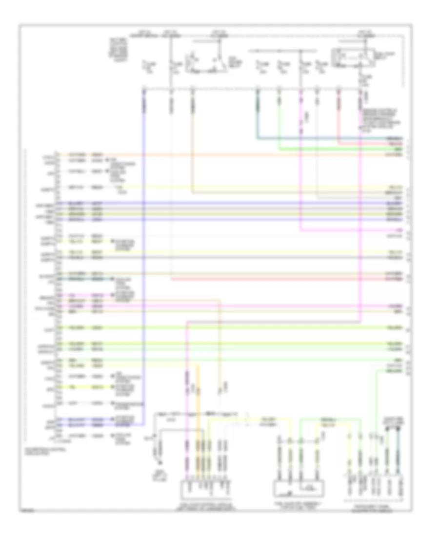
AIR CONDITIONING
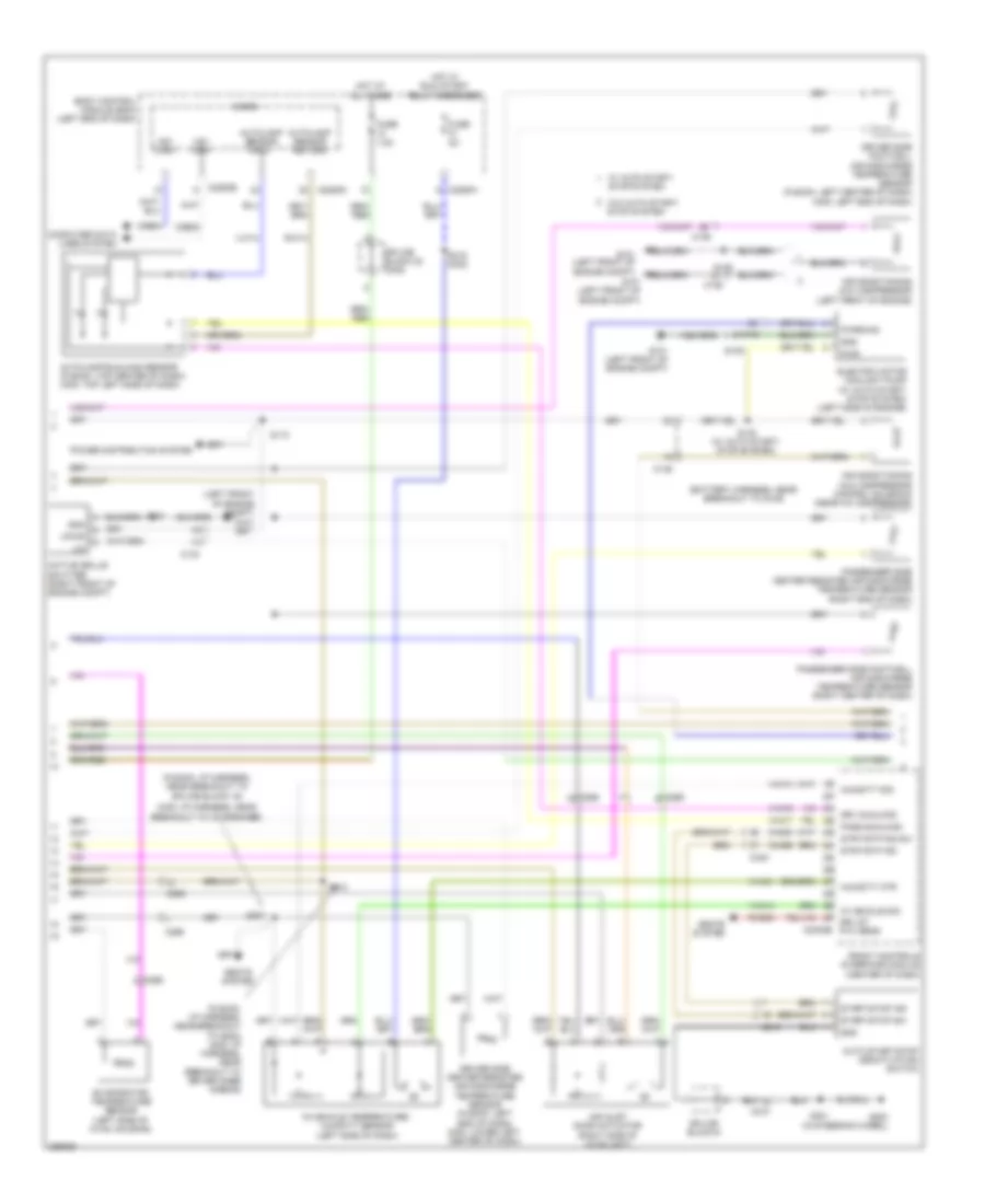
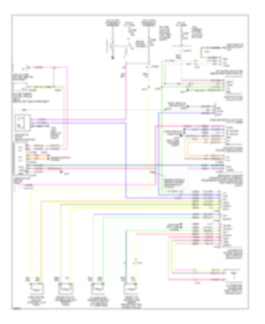
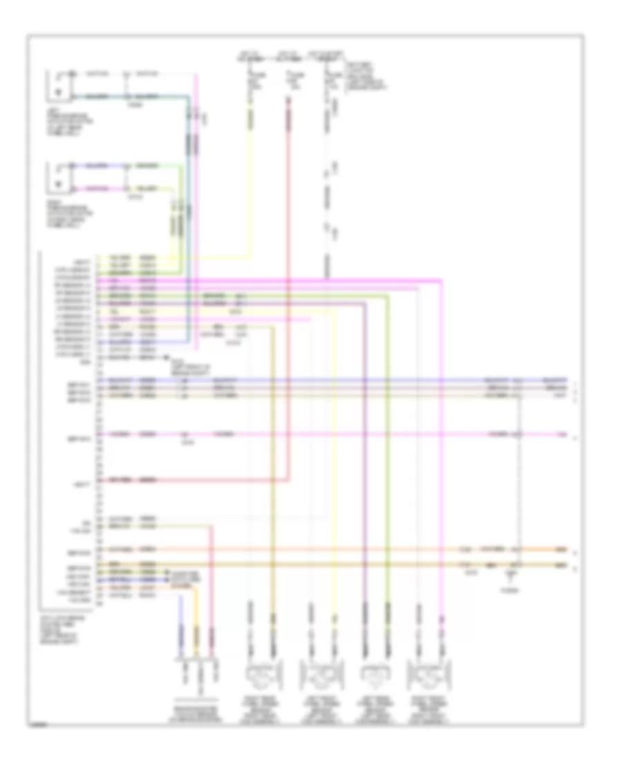
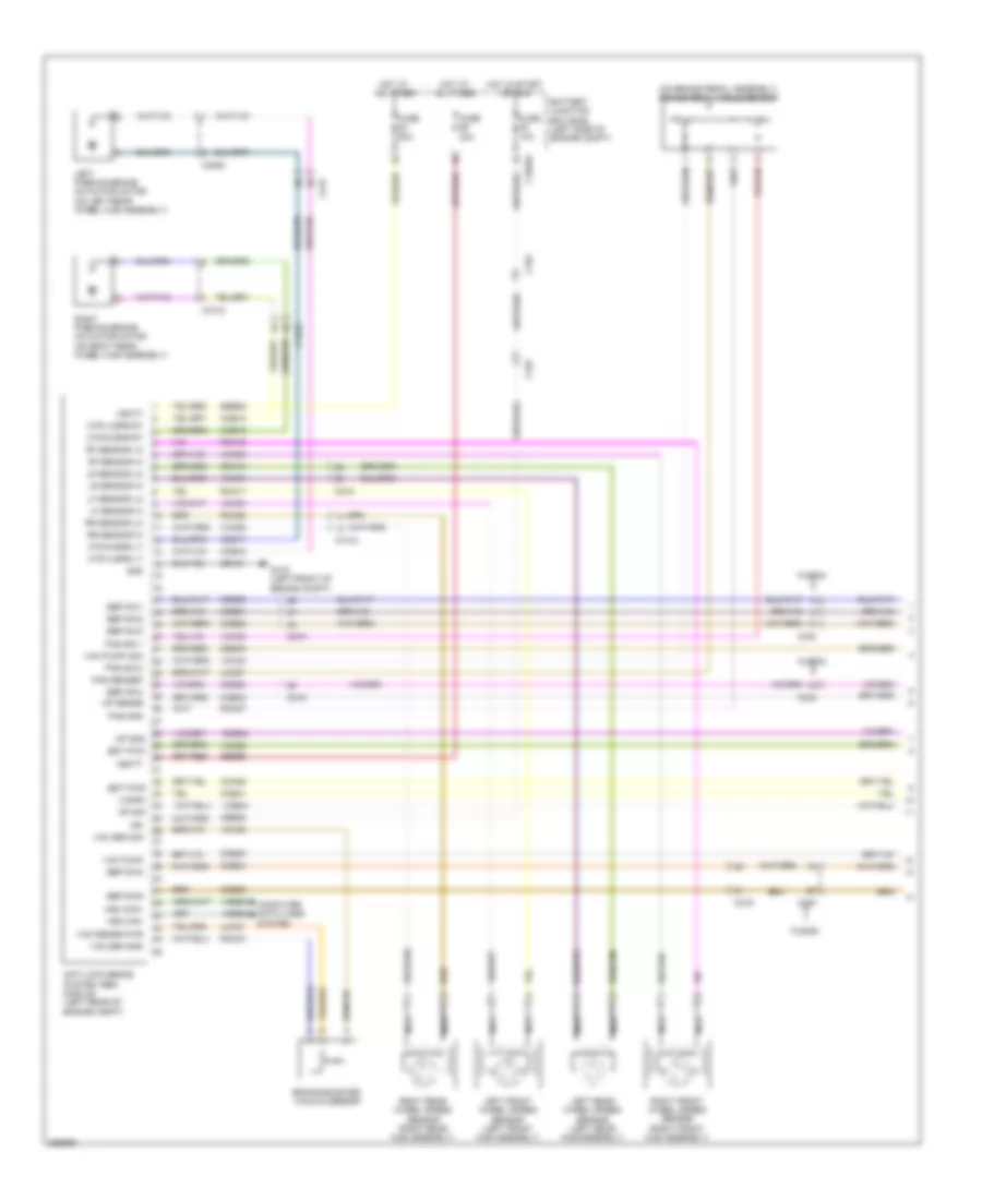
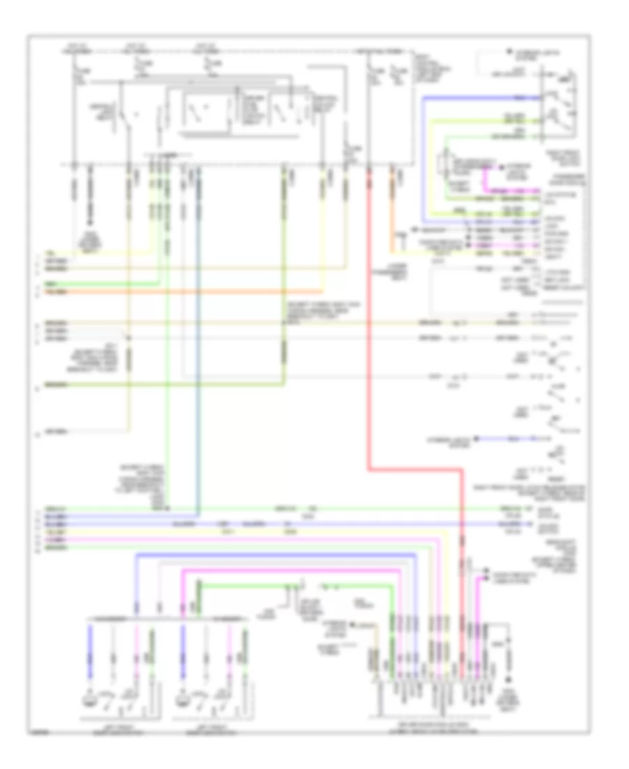
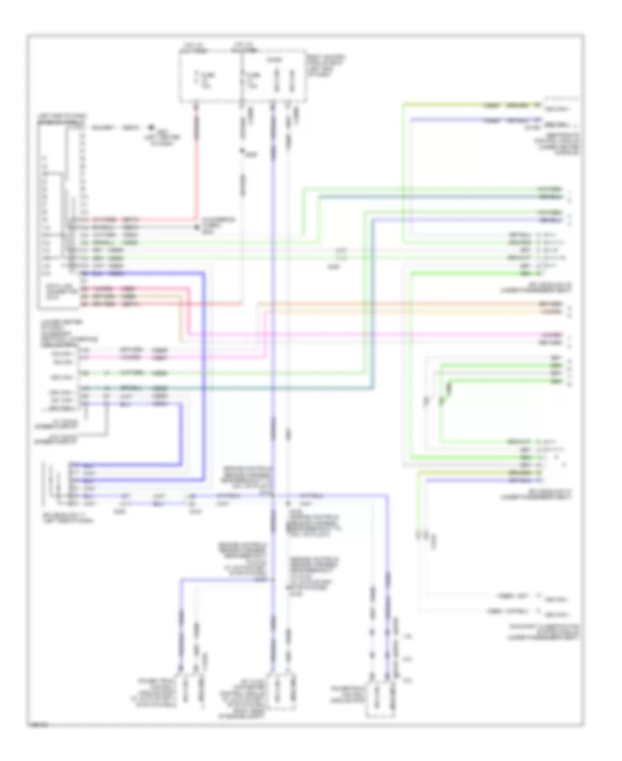
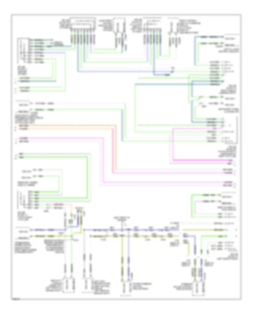
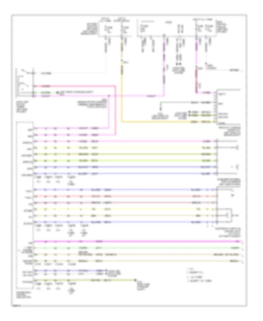
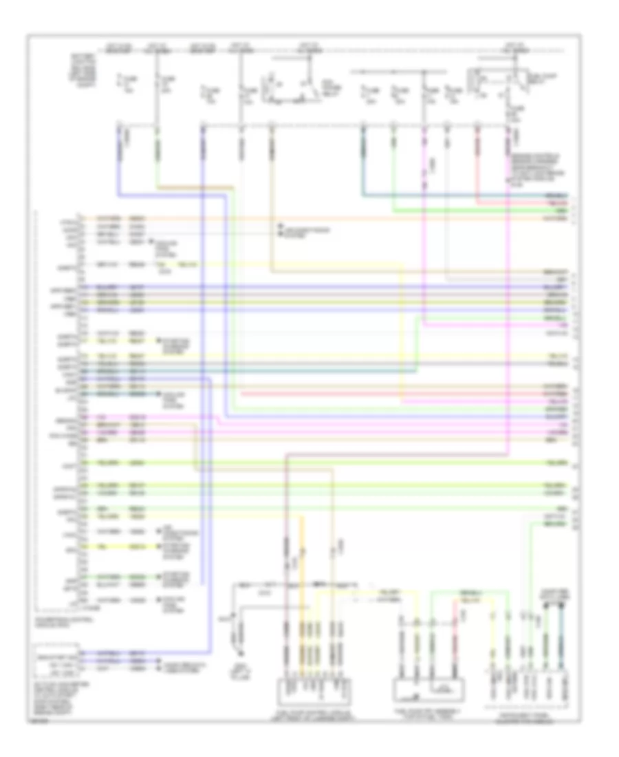
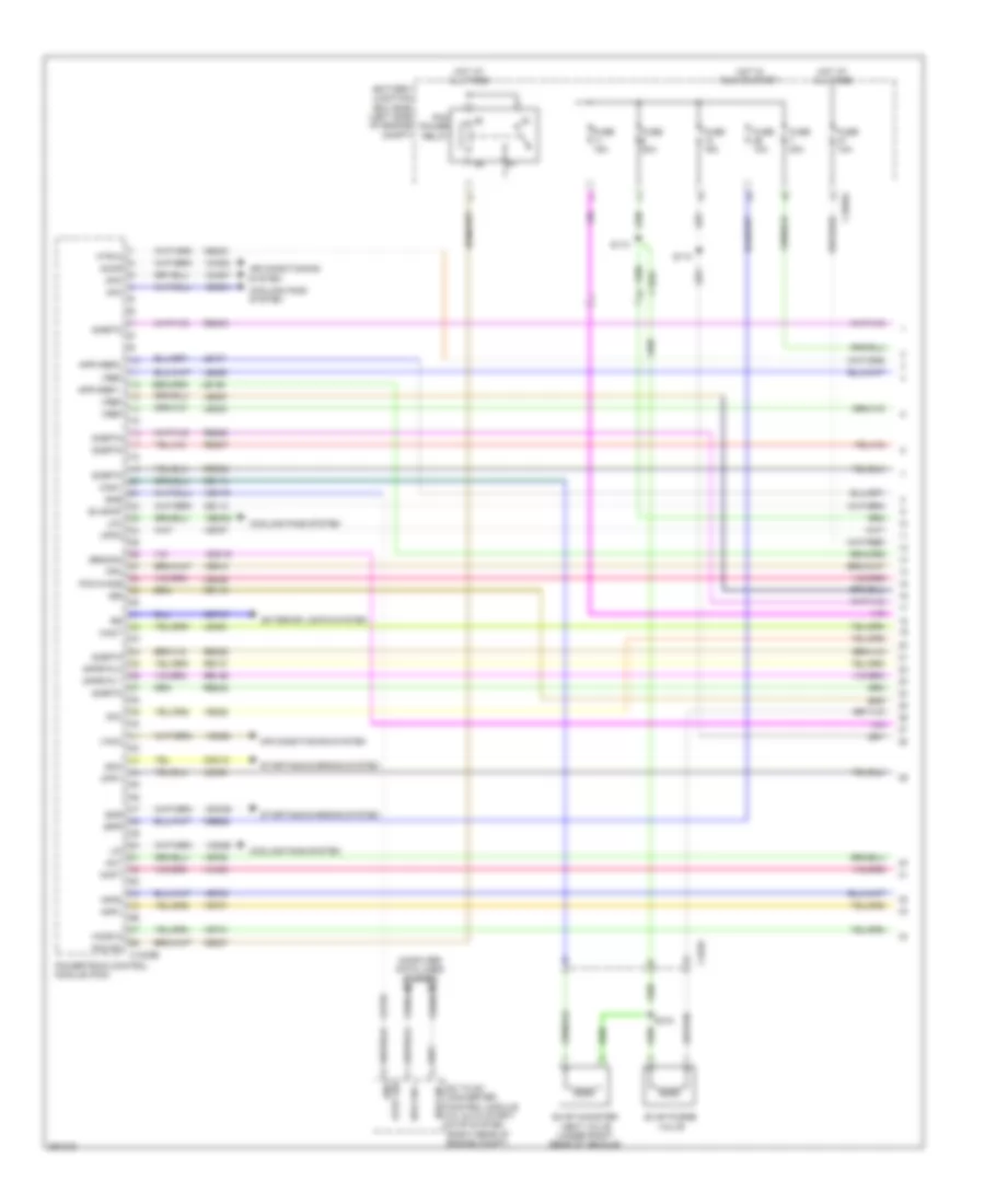
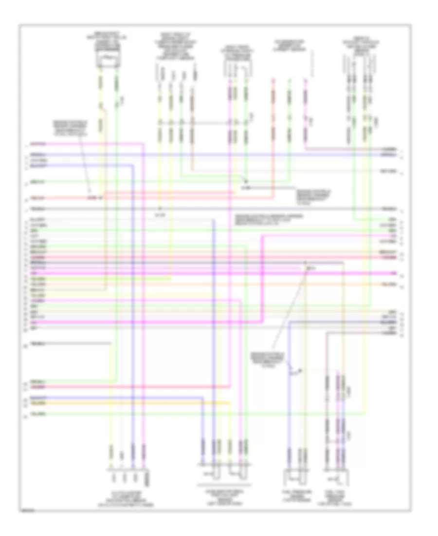
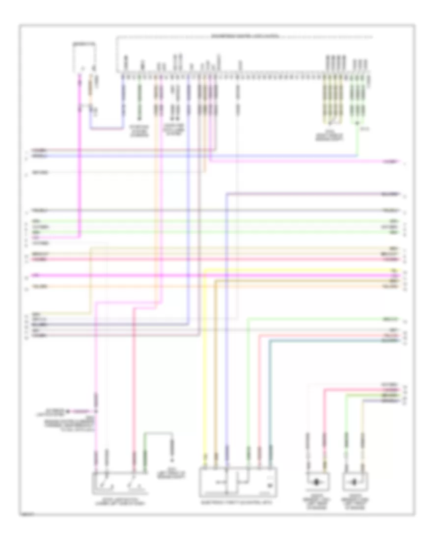
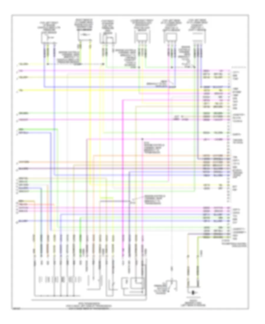
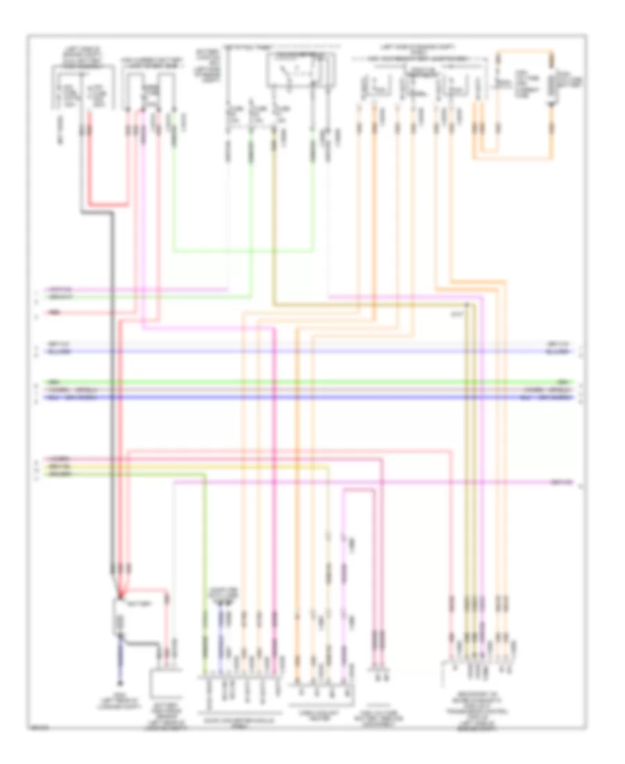
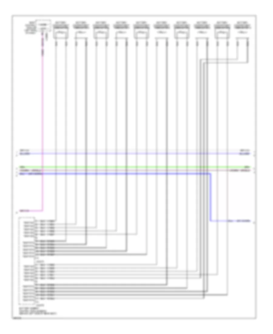
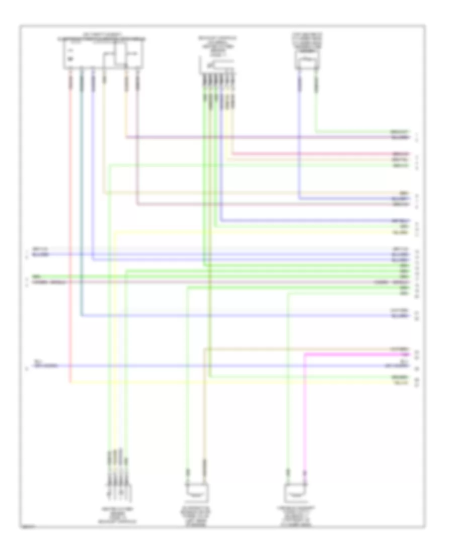
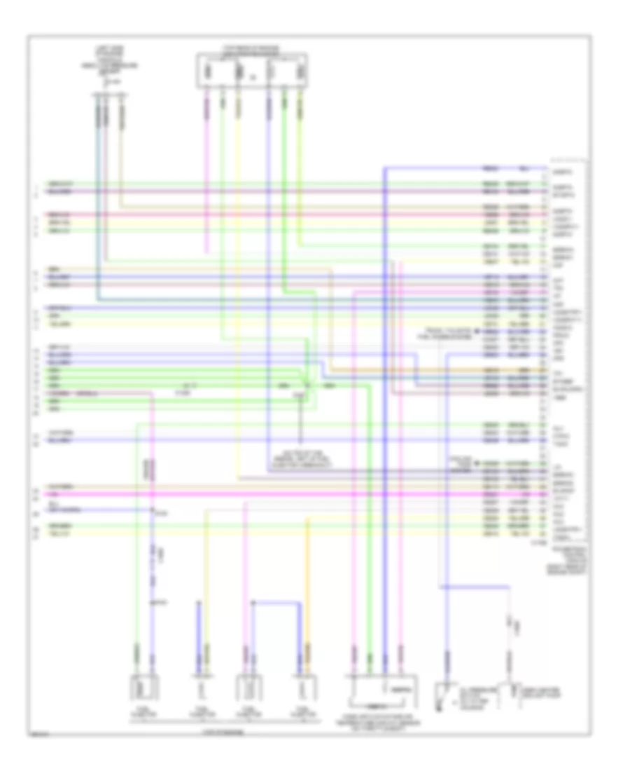
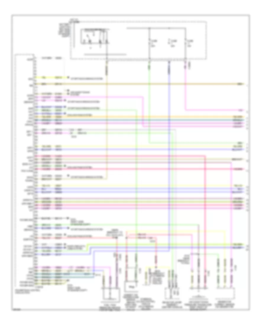
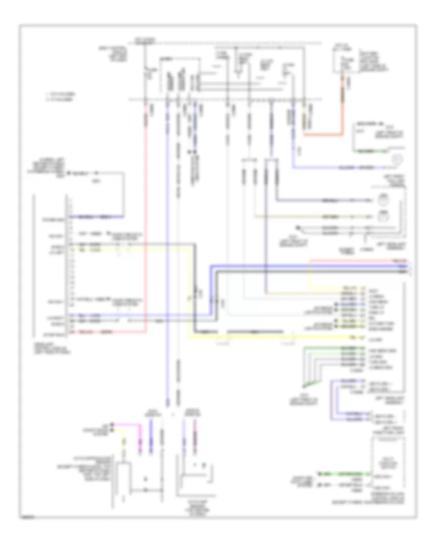
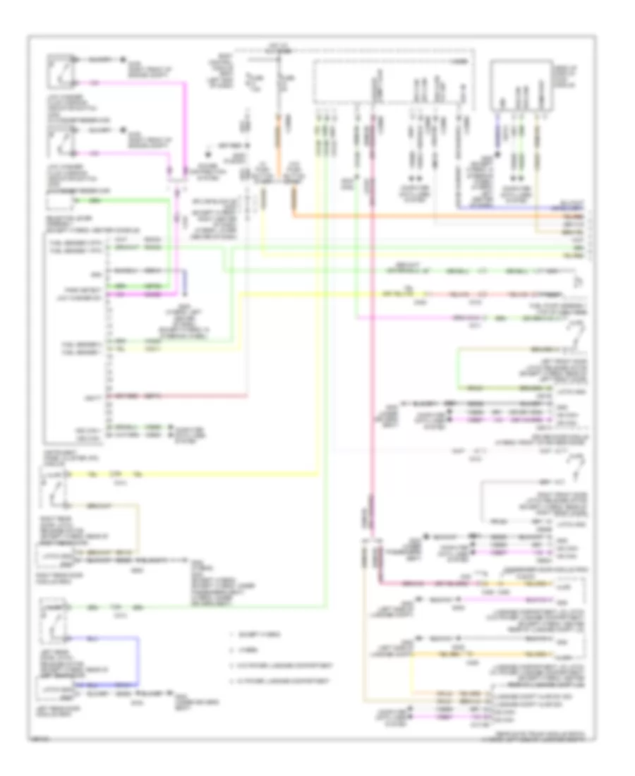
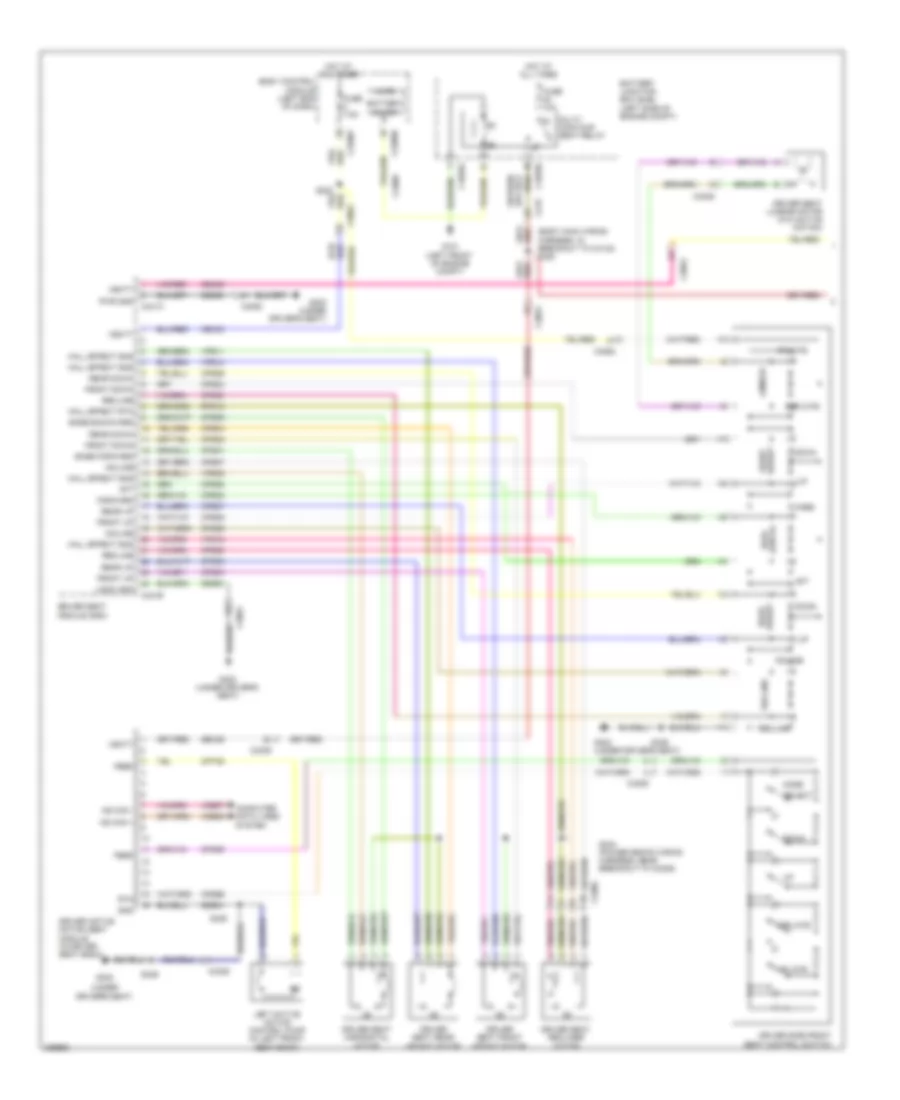
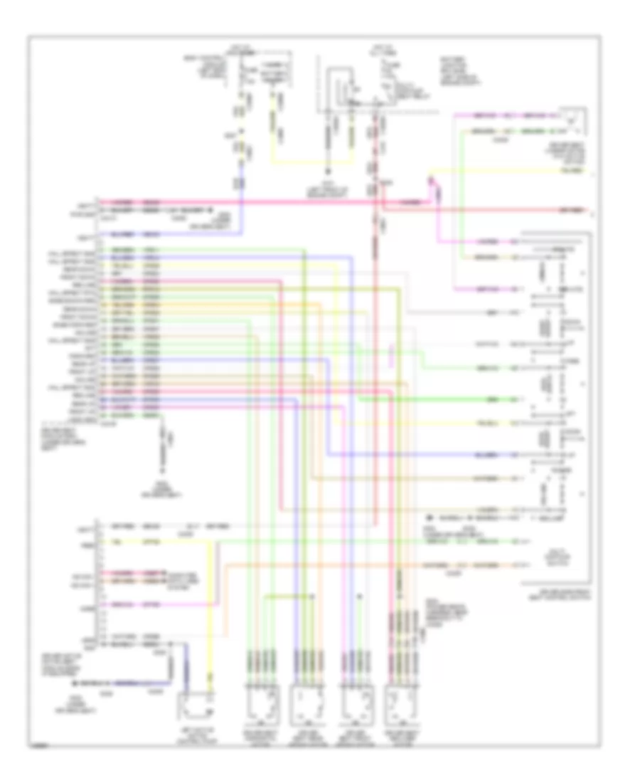
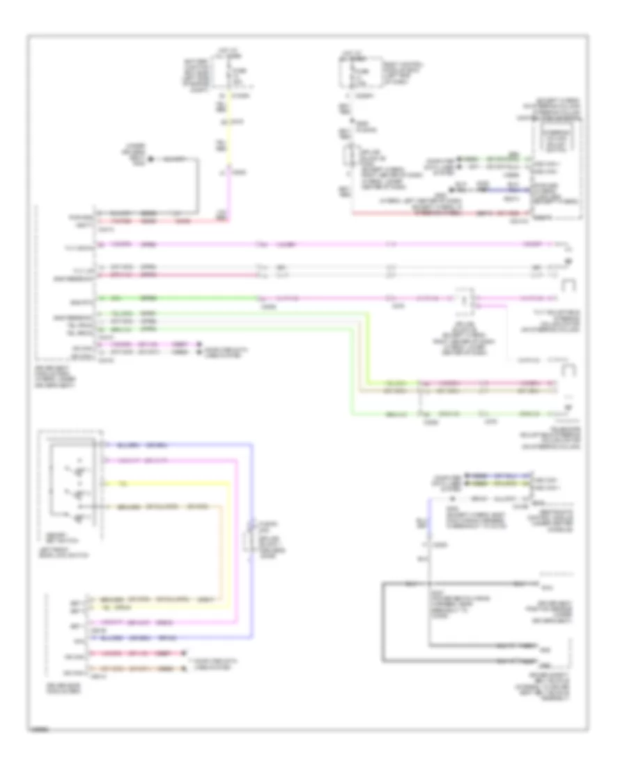
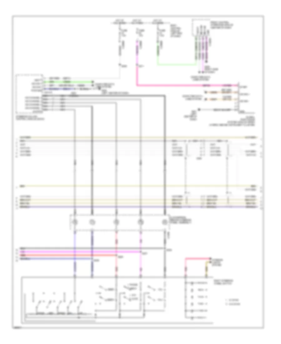
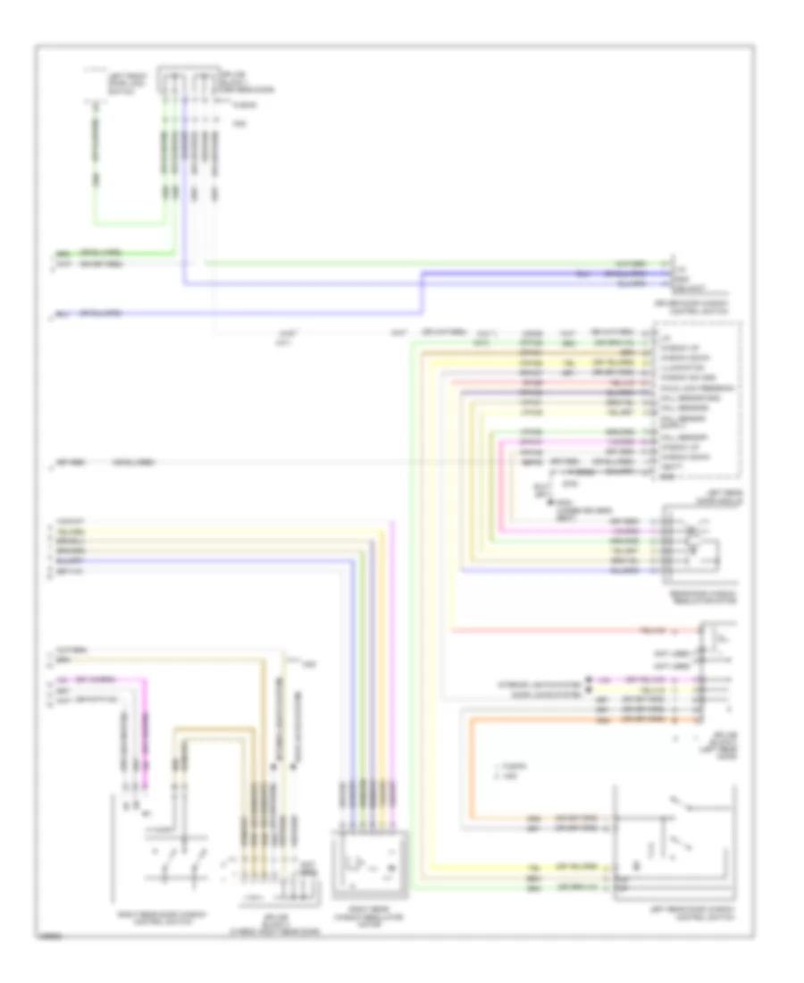
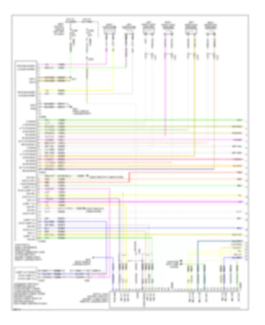
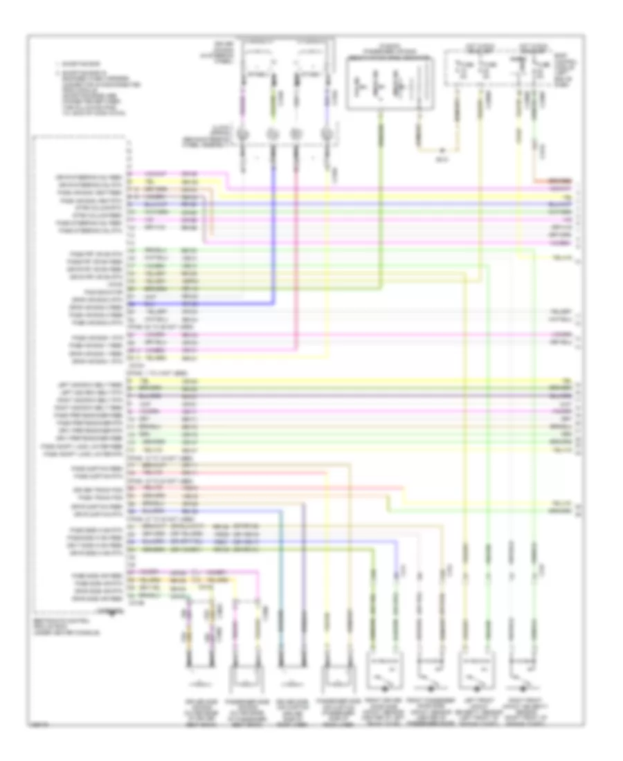
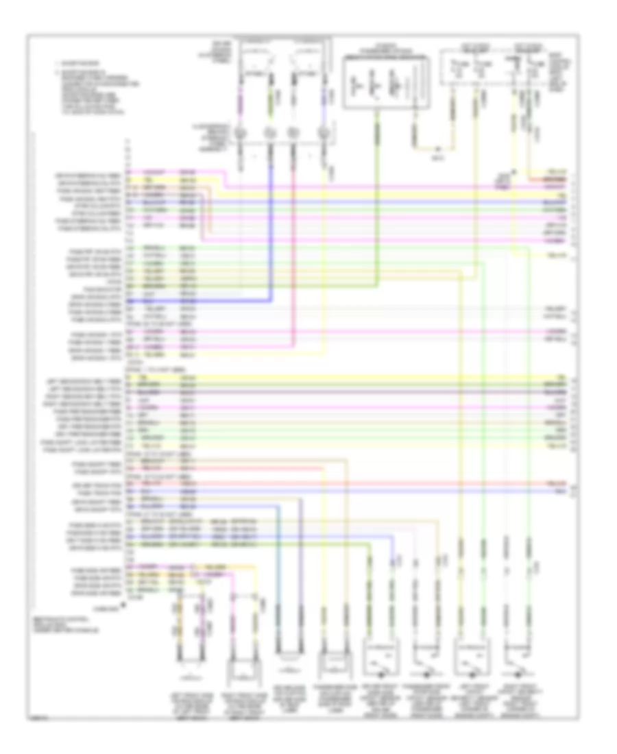
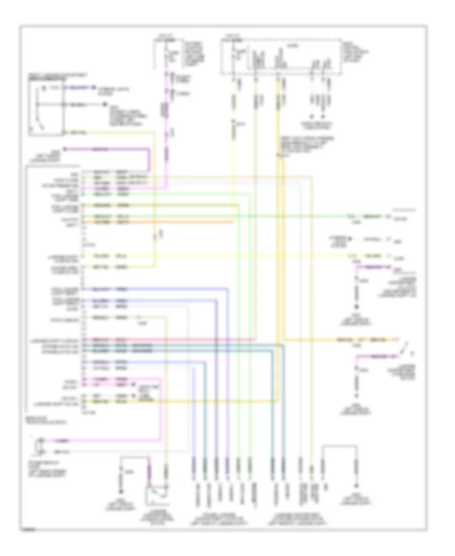
Automatic A/C Wiring Diagram, Except Hybrid (1 of 3) for Ford Fusion SE 2013
 https://portal-diagnostov.com/license.html
Automotive Electricians Portal FZCO
Automotive Electricians Portal FZCO
https://portal-diagnostov.com/license.html
https://portal-diagnostov.com/license.html
Automotive Electricians Portal FZCO
Automotive Electricians Portal FZCO
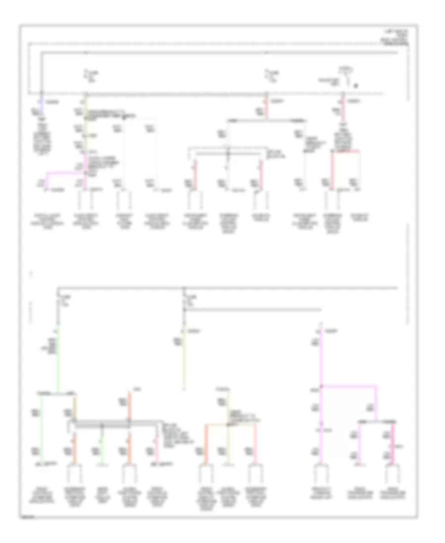
List of elements for Automatic A/C Wiring Diagram, Except Hybrid (1 of 3) for Ford Fusion SE 2013:
- (a/c jumper harness, near breakout to blower motor)
- (center of dash)
- (right side of dash) g202
- (right side of hvac unit) blower motor
- 40a
- A/c clutch relay
- Air distribution door actuator (left side of hvac unit)
- Battery junction box (bjb) (left side of engine compt)
- Blower control
- Blower motor control module (right side of hvac unit)
- Blower motor relay
- Blower relay
- C1035a
- C1035b
- C219
- C2402a
- C2402b
- C265
- C268
- C297a
- C297b
- Ch123
- Ch201
- Ch202
- Ch203
- Ch206
- Ch207
- Ch208
- Ch211
- Ch212
- Ch213
- Ch237
- Ch238
- Ch239
- Ch402
- Chs02
- Chs07
- Computer data lines system
- Crd02
- Defogger system
- Defrost request
- Driver temperature door actuator (left side of hvac unit)
- Drv frt snsr 1
- Drv frt snsr 2
- Drv heater feed
- Evap
- Feedback
- Front controls interface module
- Fuse
- Fuse 10a
- Fuse 15a
- Fuse 20a
- G101 (left front of engine compt)
- G202 (right side of dash)
- Gd216
- Gnd
- Hot at all times
- Hot w/ pcm power relay energized
- Lh111
- Motor+
- Motor-
- Ms can+
- Ms can-
- Pass frt snsr 1
- Pass frt snsr 2
- Pass heater feed
- Pass st ntc sens
- Passenger temperature door actuator (right side of hvac unit)
- Red
- Rh111
- Rh301
- Rhs10
- S202
- S203 (a/c jumper harness, near breakout to blower motor)
- S210
- Sbb65
- Sbp12
- Seats system
- Sig rtn
- Vbatt
- Vdb06
- Vdb07
- Vh101
- Vh301
- Vh406
- Vh409
- Vh410
- Vh411
- Vh412
- Vref
- W/ heated seats
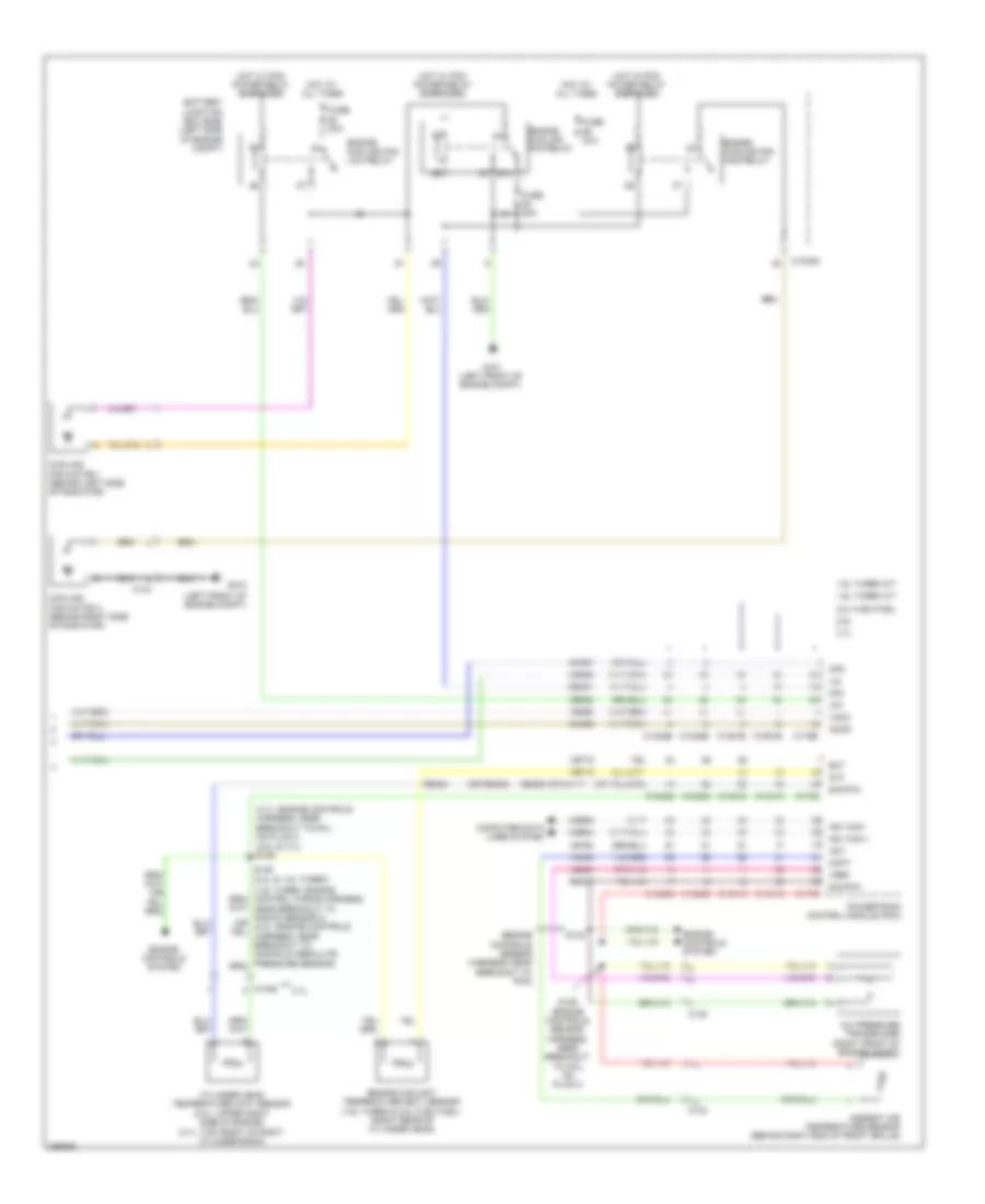
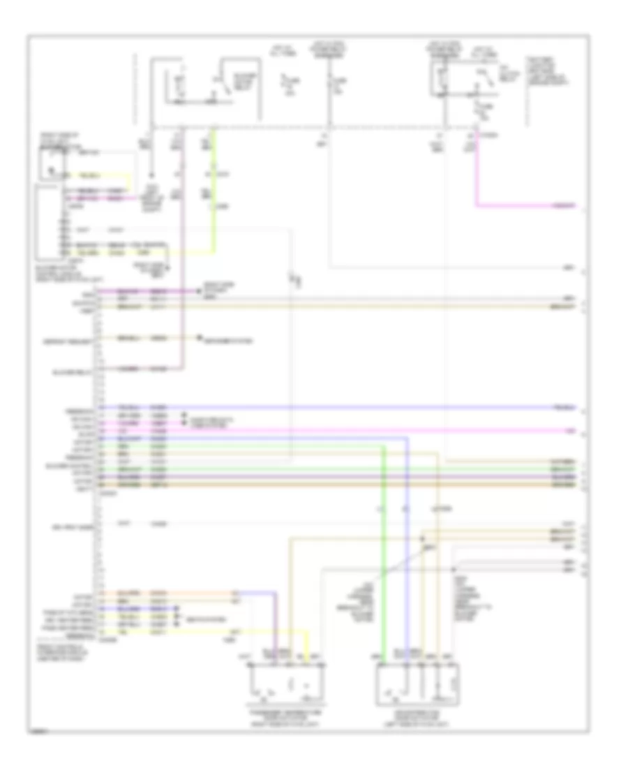
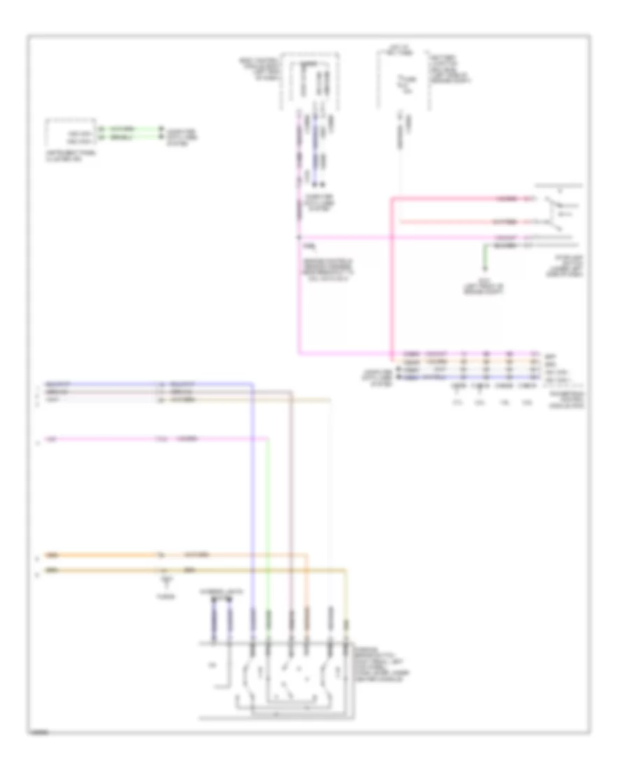
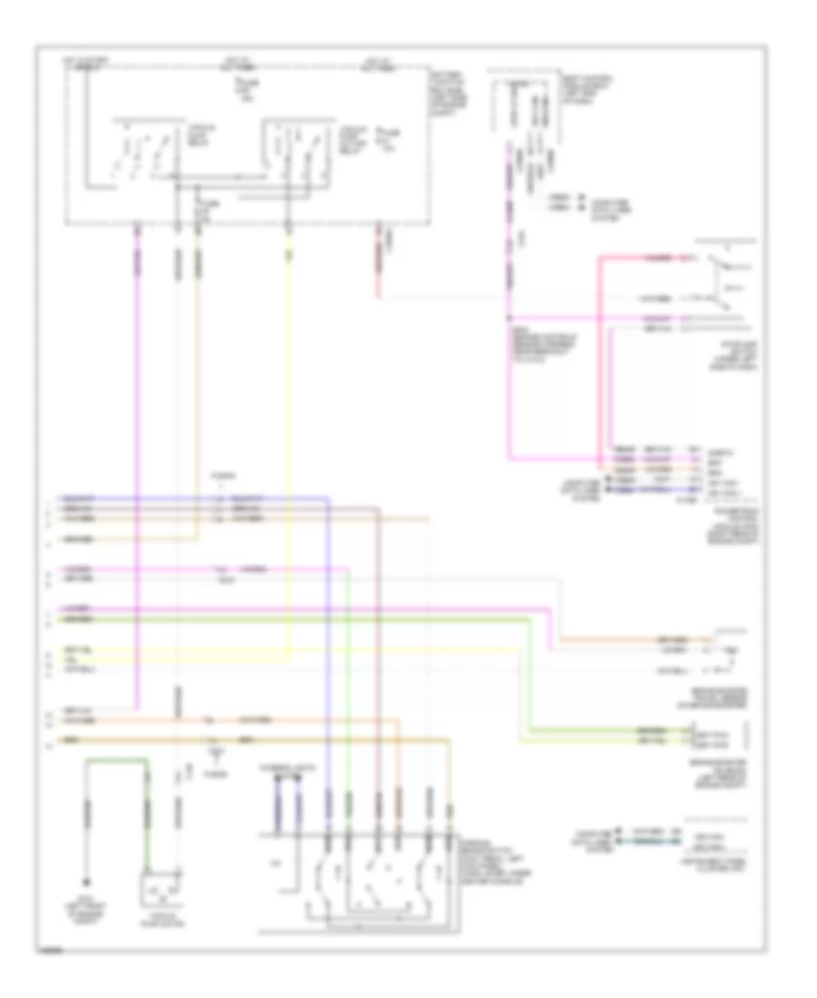
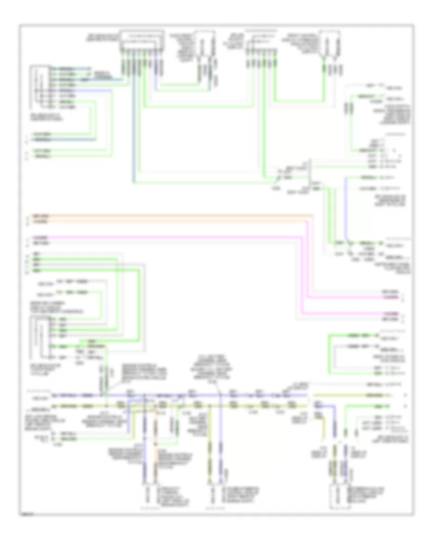
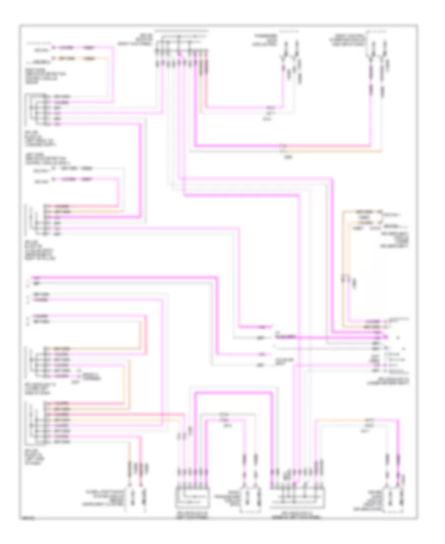
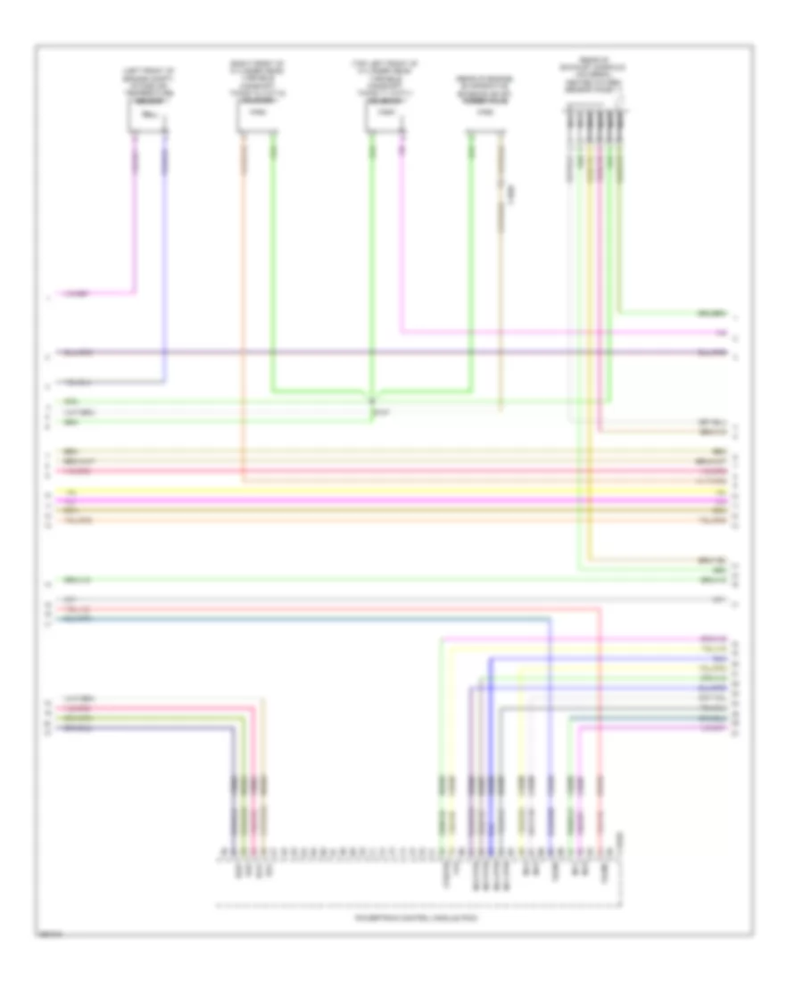
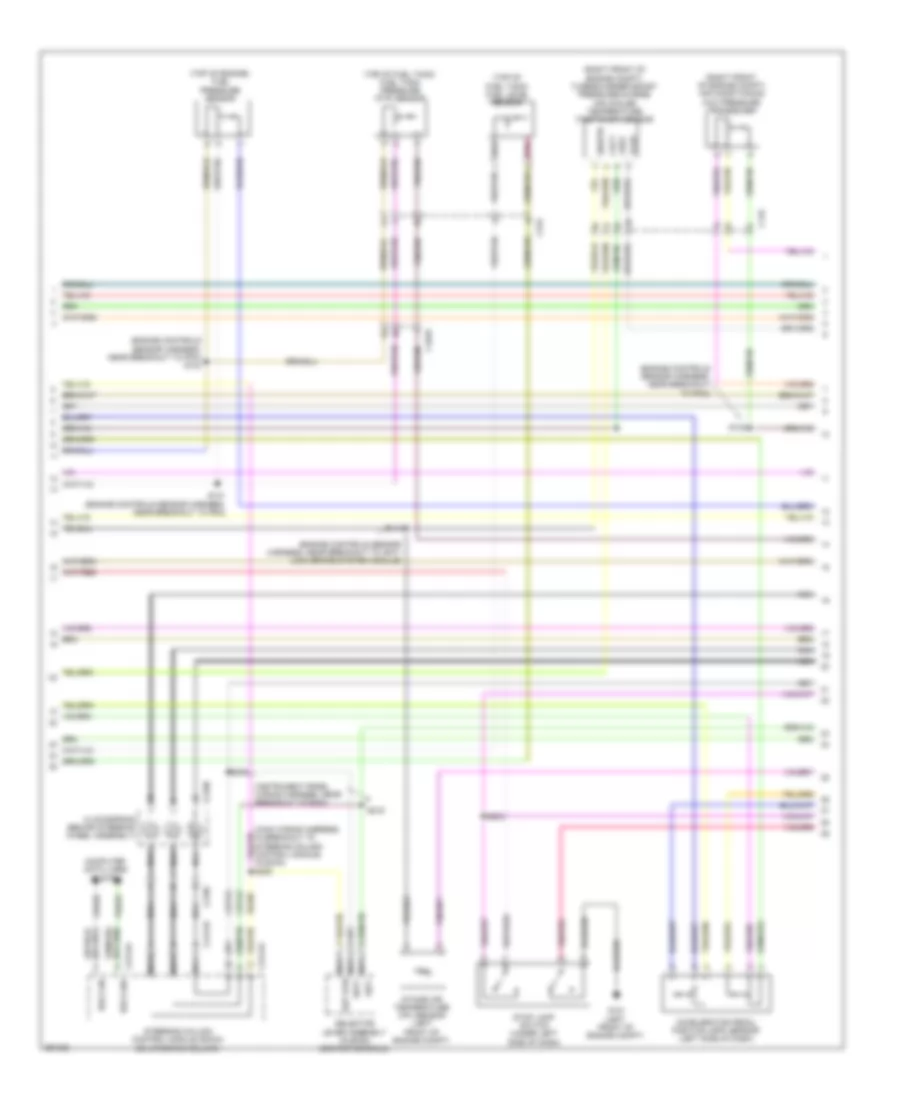
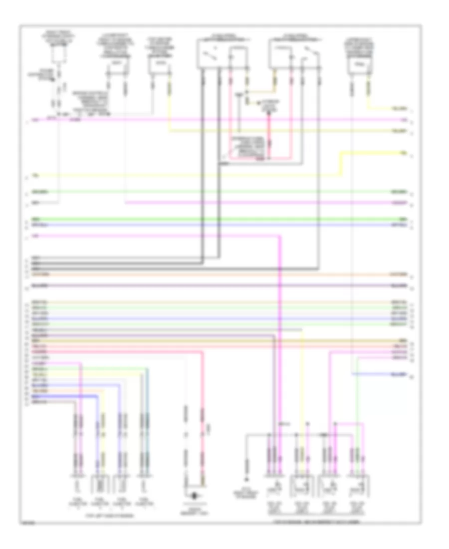
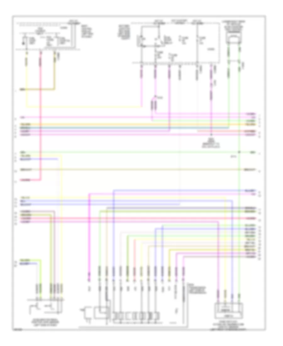
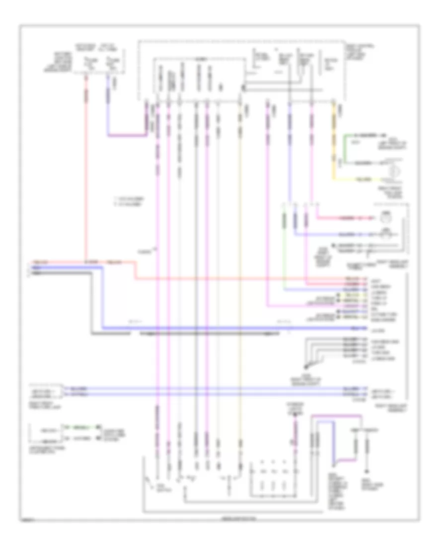
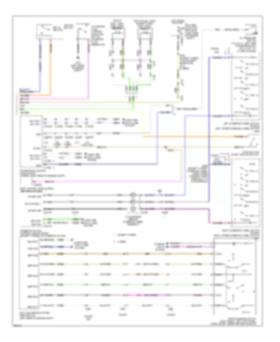
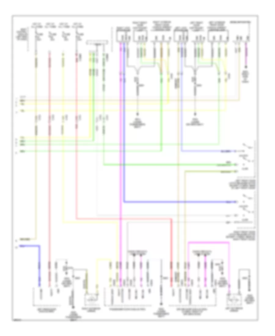
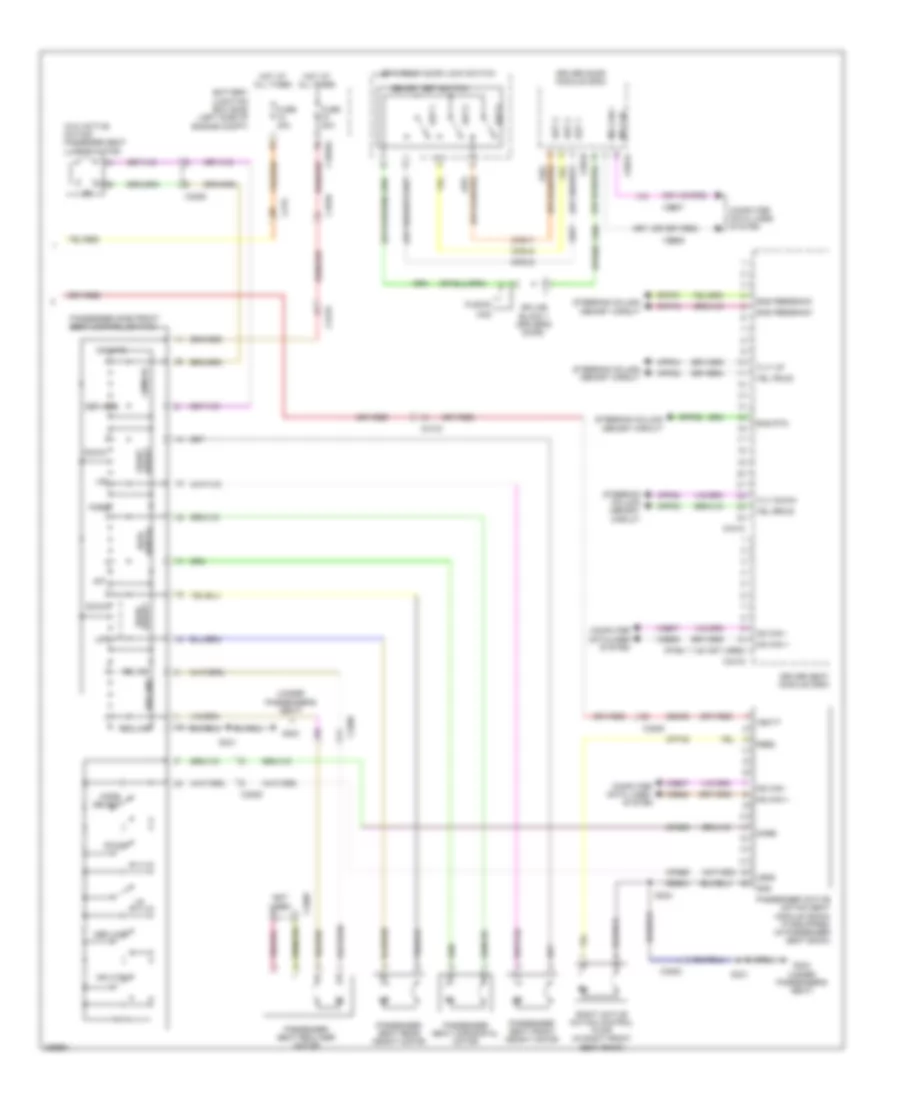
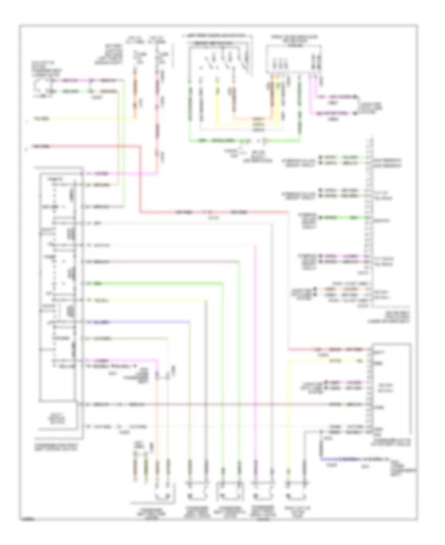
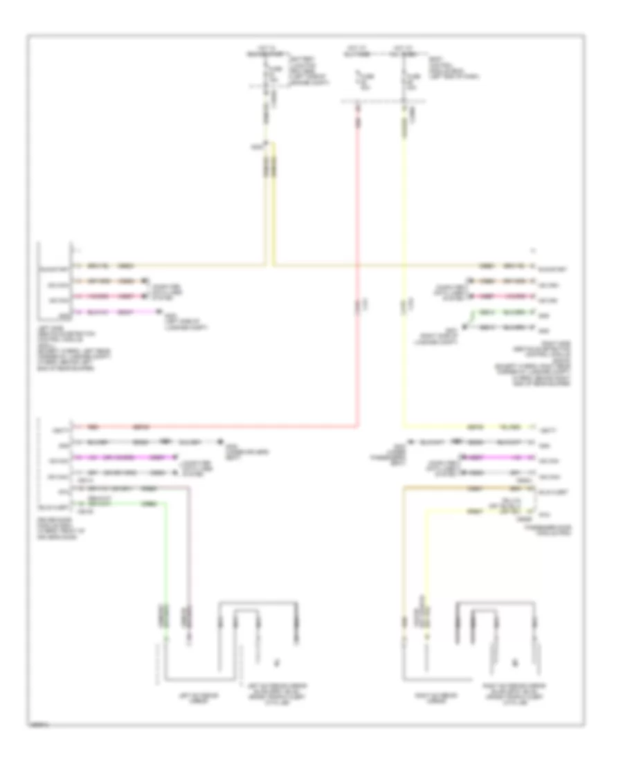
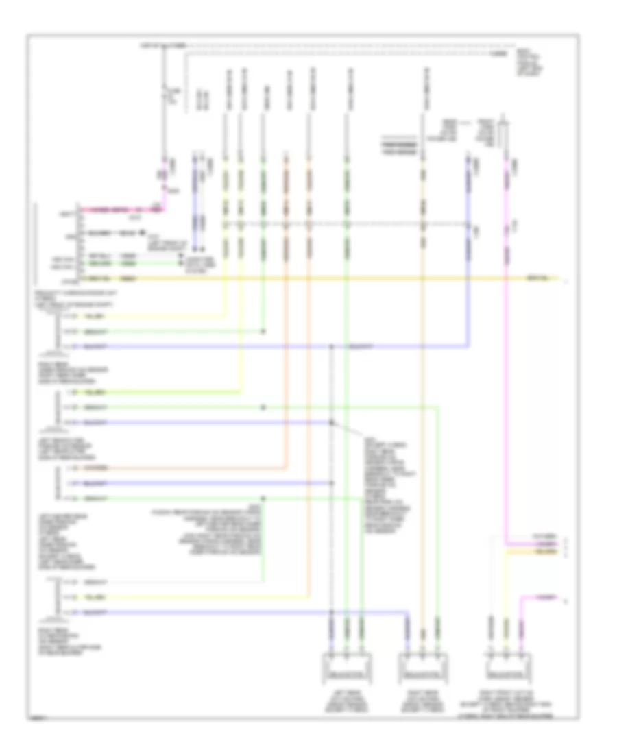
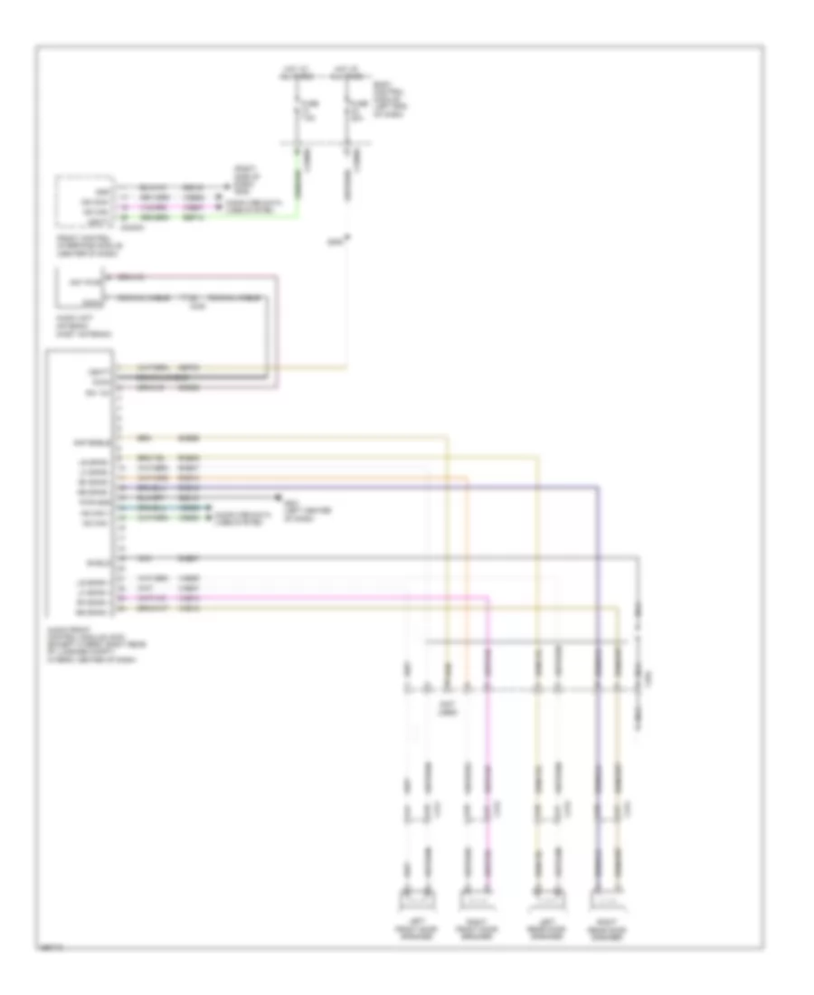
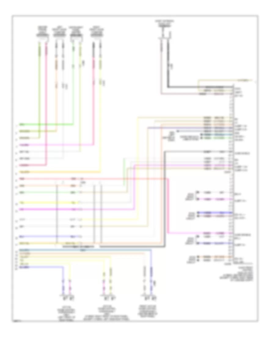
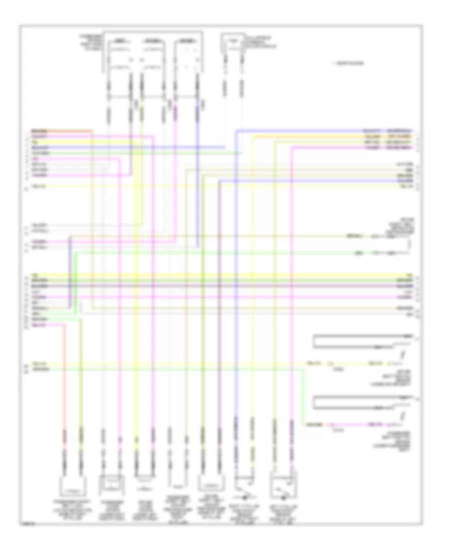
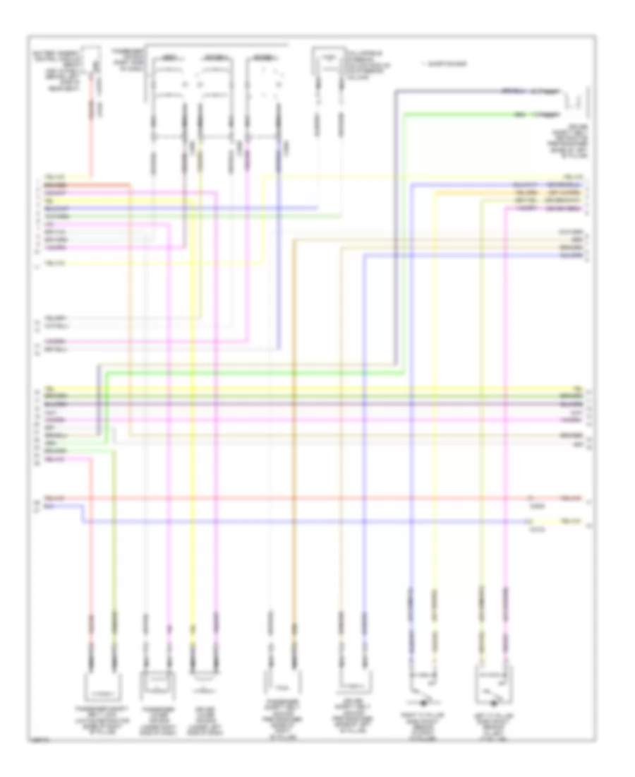
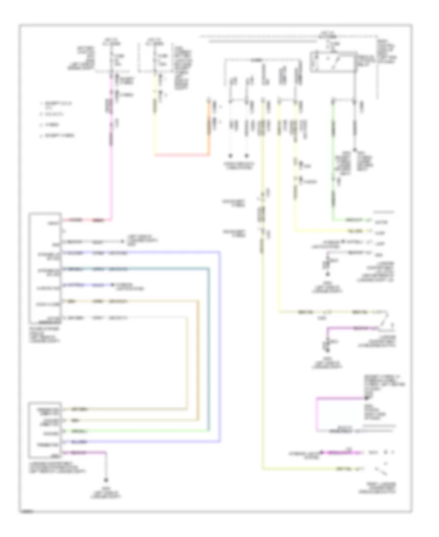
Automatic A/C Wiring Diagram, Except Hybrid (2 of 3) for Ford Fusion SE 2013
List of elements for Automatic A/C Wiring Diagram, Except Hybrid (2 of 3) for Ford Fusion SE 2013:
- (battery harness, near breakout to g109)
- (center of dash)
- (fusion: i/p harness, near breakout to g202) (mkz: i/p harness, near breakout to driver knee airbag)
- (fusion: i/p harness, near breakout to splice block 19)
- (left front of engine compt)
- (mkz: i/p harness, near
- Active grille shutter (right front of engine compt)
- Air conditioning (a/c) compressor (left front of engine)
- Air conditioning (a/c) compressor control solenoid (near a/c compressor)
- Air inlet door actuator (right side of hvac unit)
- Auto start/stop deactivation switch
- Autolamp sensor input
- Autolamp sensor return
- Autolamp/sunload sensor (fusion: top center of dash) (mkz: top left side of dash)
- Body control module (bcm) (left end of dash)
- Breakout to i/p speaker)
- C134
- C146
- C210
- C2280b
- C2280g
- C2280h
- C2402b
- C265
- C340
- Ch253
- Ch469
- Computer data lines system
- Driver side center register air discharge temperature sensor (fusion: left end of dash) (mkz: lower left center of dash)
- Driver side footwell air discharge temperature sensor (fusion: left center of dash) (mkz: left end of dash)
- Drv st ntc sens
- Drv sunload
- Electric motor coolant pump (w/ auto start/ stop system) (left side of engine)
- Evaporator temperature sensor (left side of hvac housing)
- Front controls interface module
- Fuse 5a
- Fuse 7.5a
- G101
- G101 (left front of engine compt)
- G200 (in steering wheel)
- Gnd
- Hot at all times
- Hot w/ run/ start relay energized
- Hs1 can+
- Hs1 can-
- Humidity mtr
- Humidity sig
- In vehicle sig
- In-vehicle temperature/ humidity sensor (left side of dash)
- Lin
- Micro
- Pass sunload
- Passenger side center register air discharge temperature sensor (right end of dash)
- Passenger side footwell air discharge temperature sensor (right center of dash)
- Power distribution system
- Pwr
- Pwr/diag
- Rhs05
- Rlf14
- S101
- S110
- S139
- S140 (w/ auto start/ stop system)
- S207
- S213
- S219 (mkz)
- S301
- Seats system
- Splice block 22 (mkz)
- Splice block 6
- Start/stop ind
- Start/stop sw
- Stop system
- Strt/stp dis sw
- Strt/stp ind
- Vdb04
- Vdb05
- Vh413
- Vh414
- Vh416
- Vh417
- Vha31
- Vlf14
- Vpwr
- W/ auto start/
- W/o auto start/ stop system
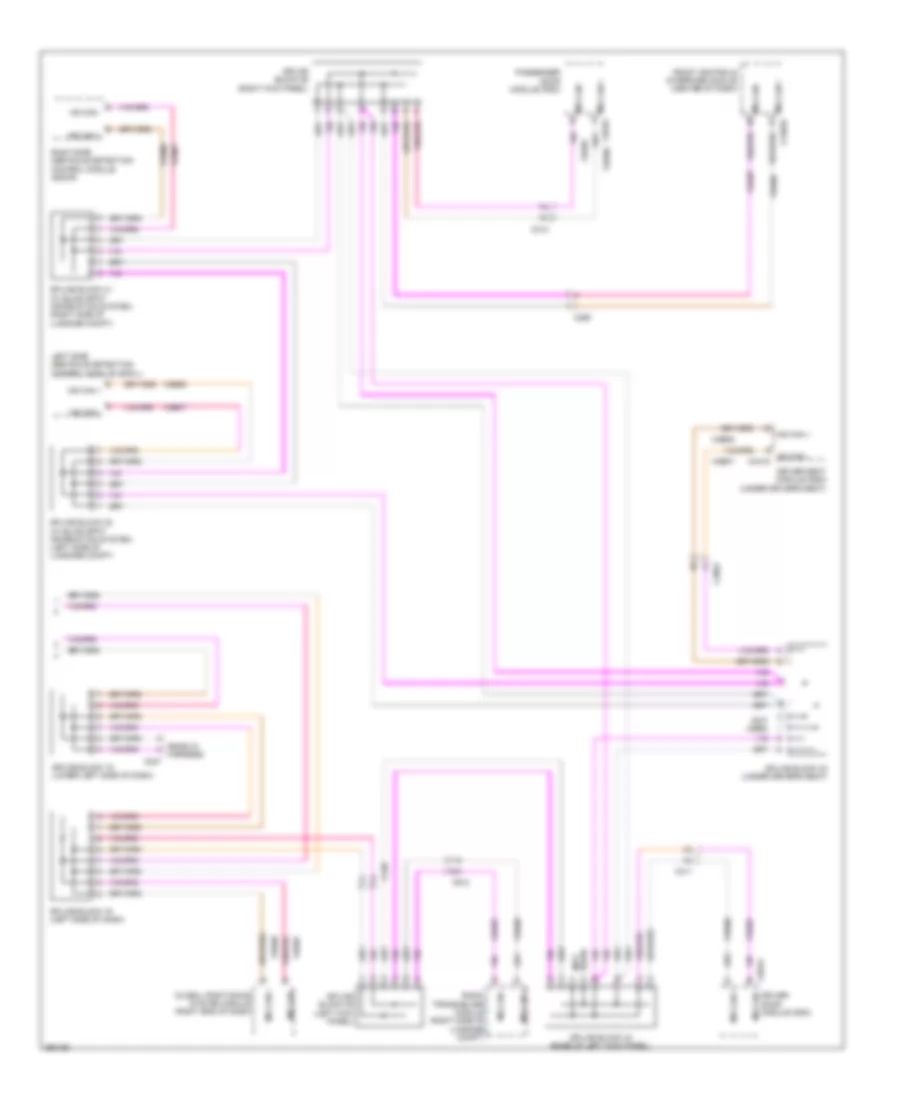
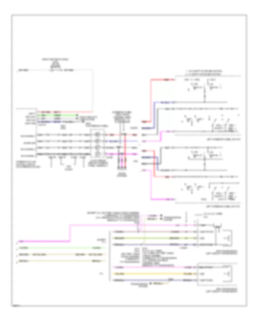
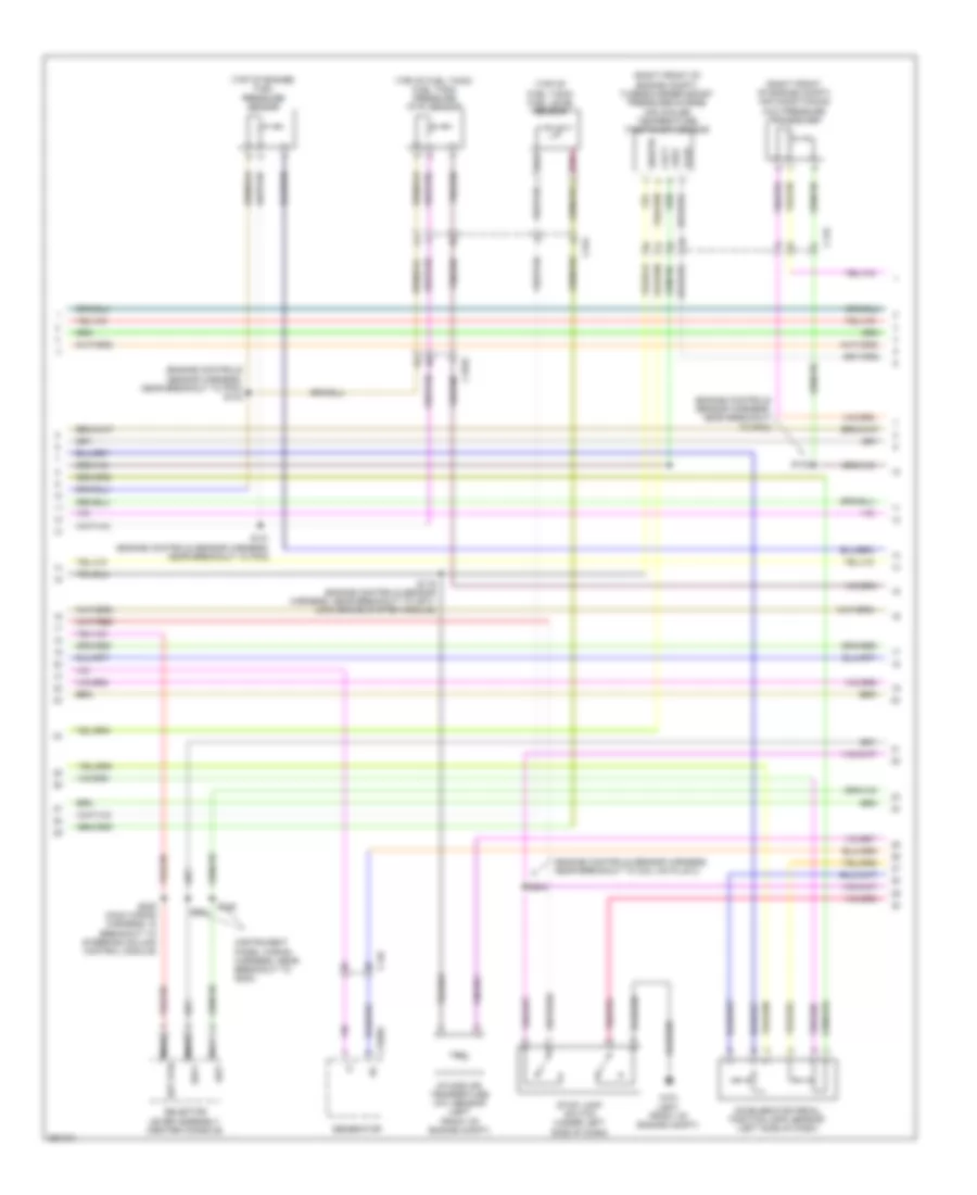
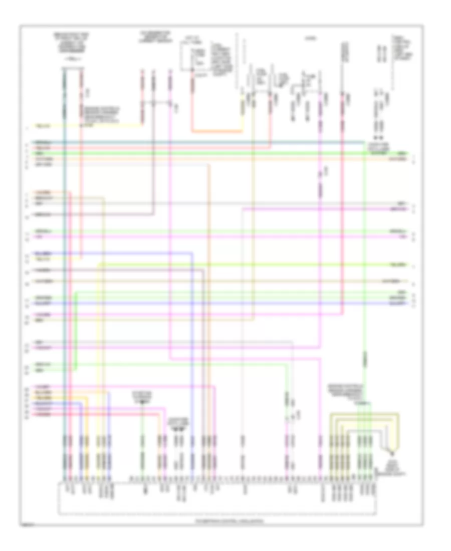
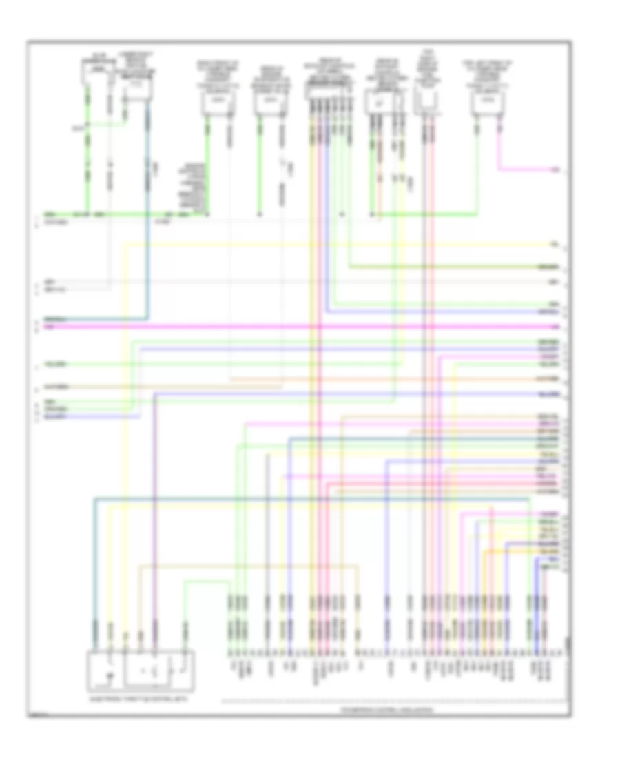
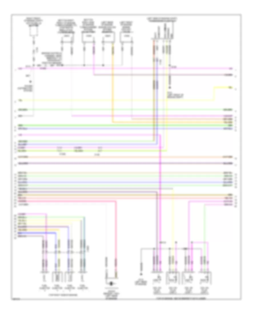
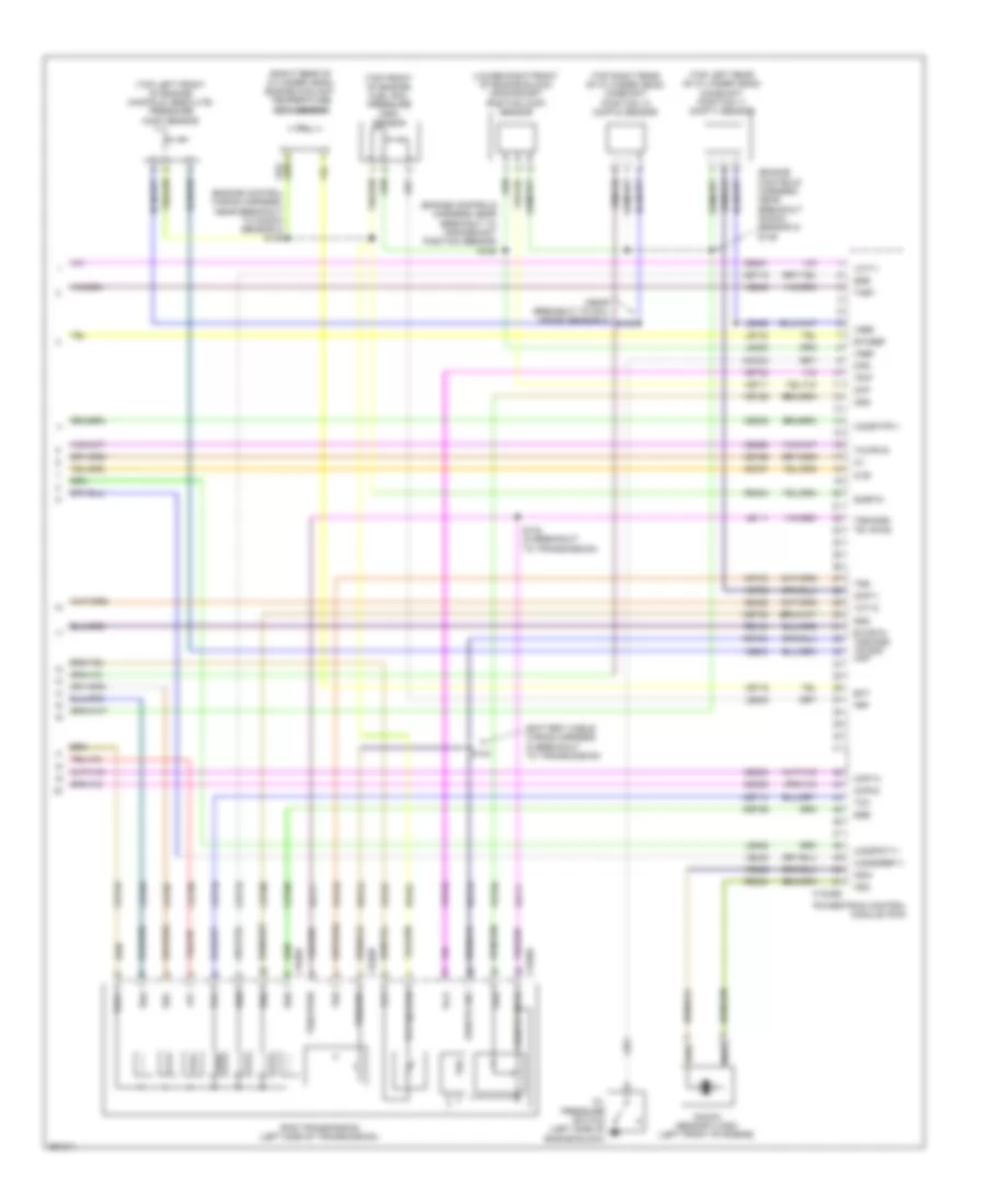
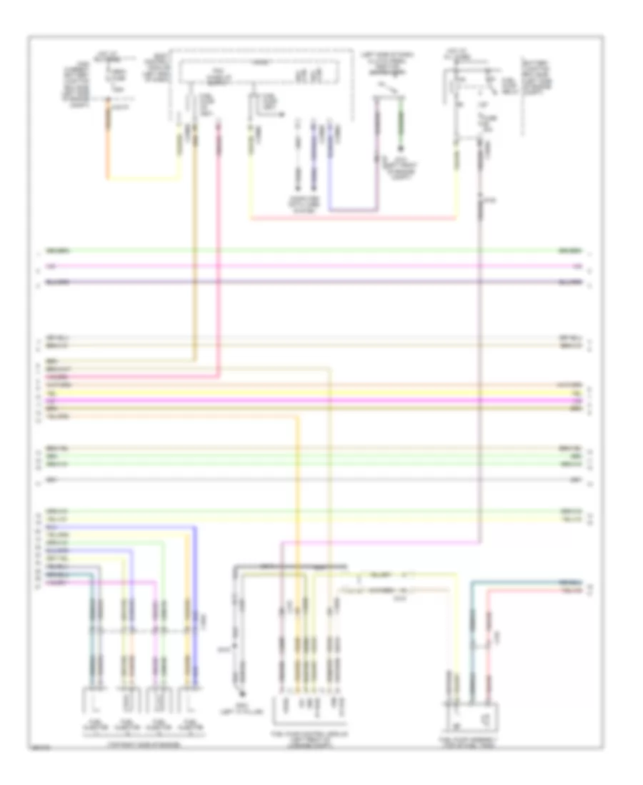
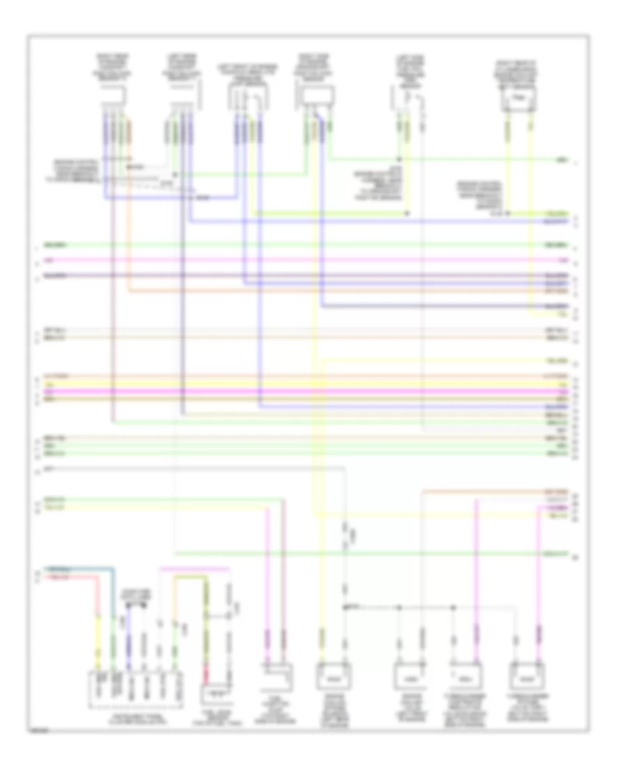
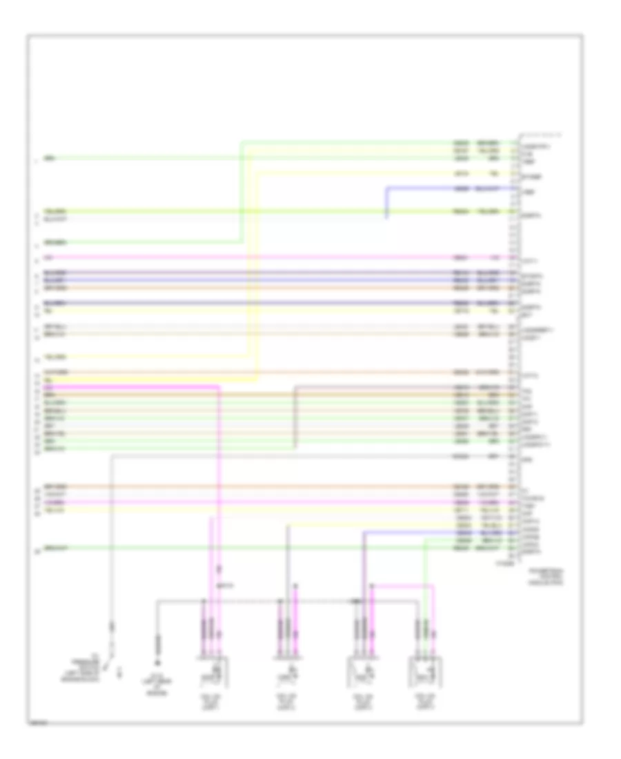
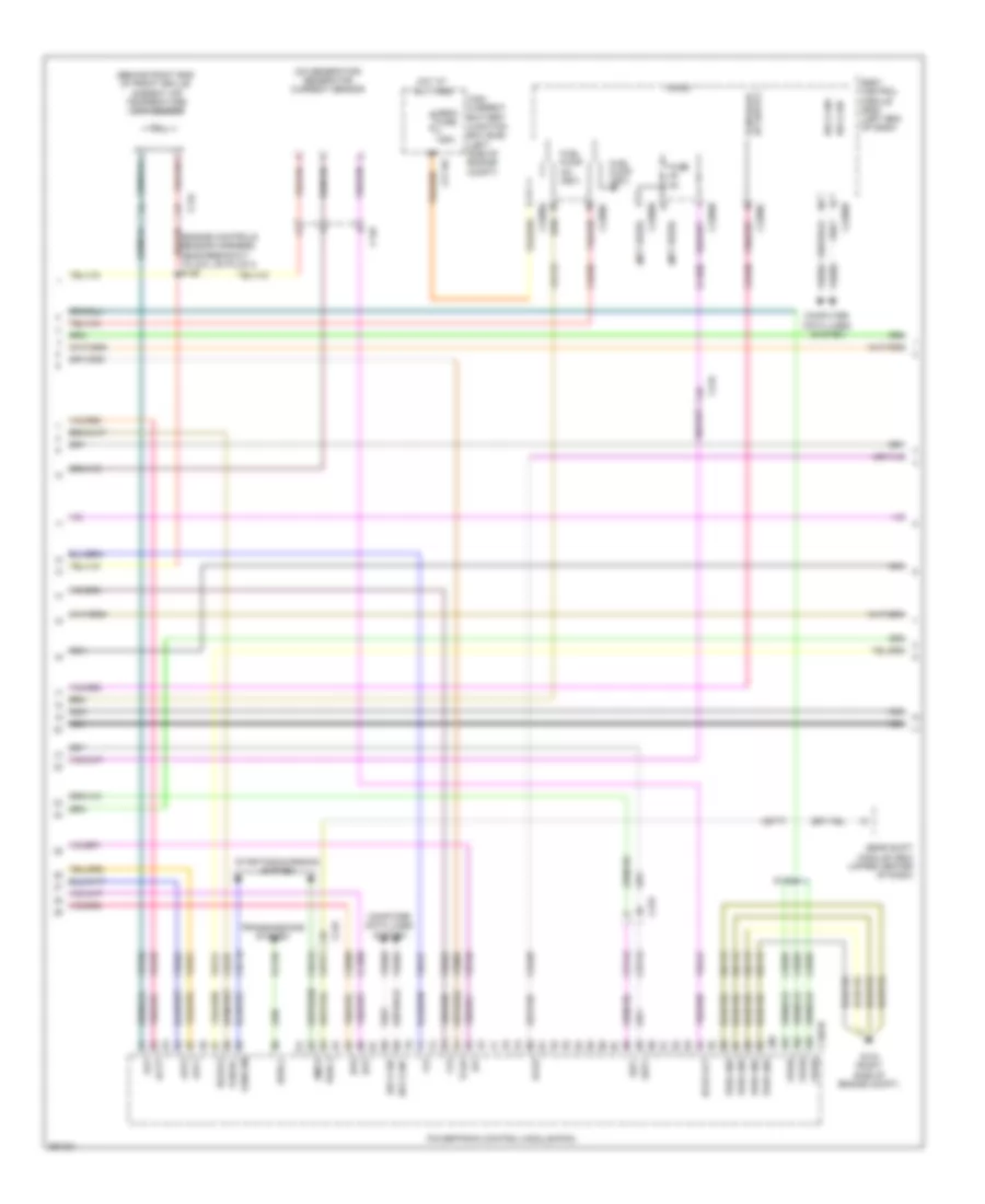
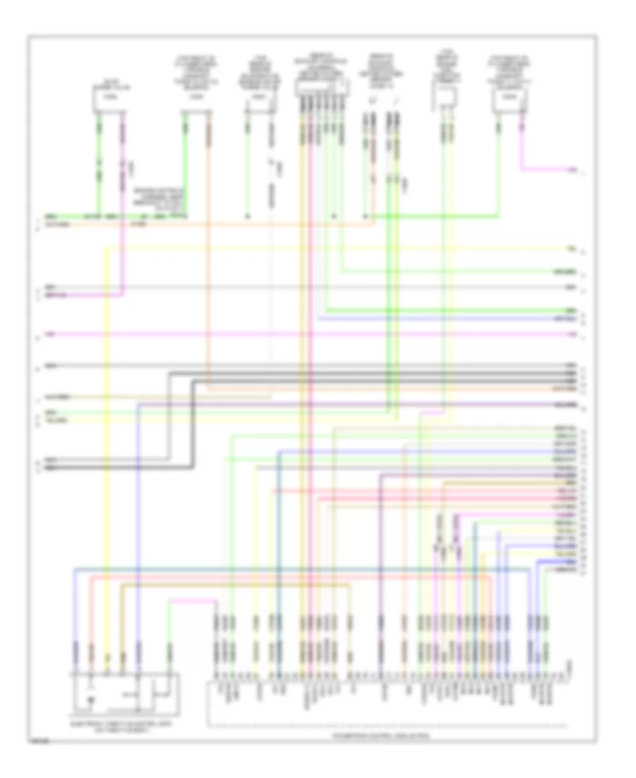
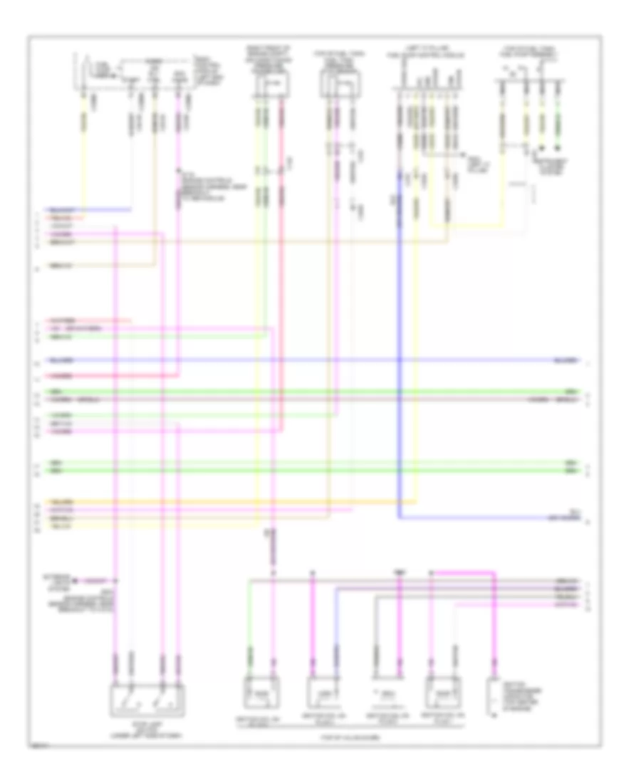
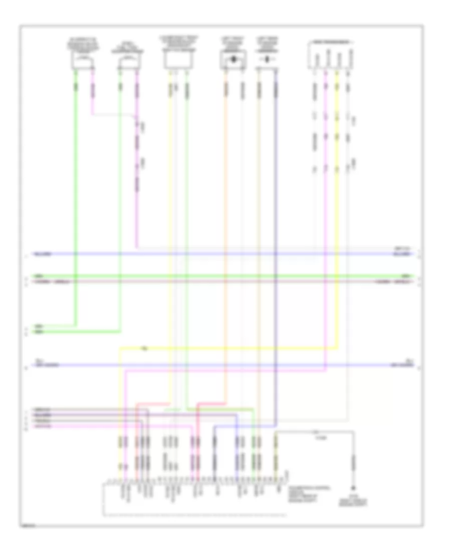
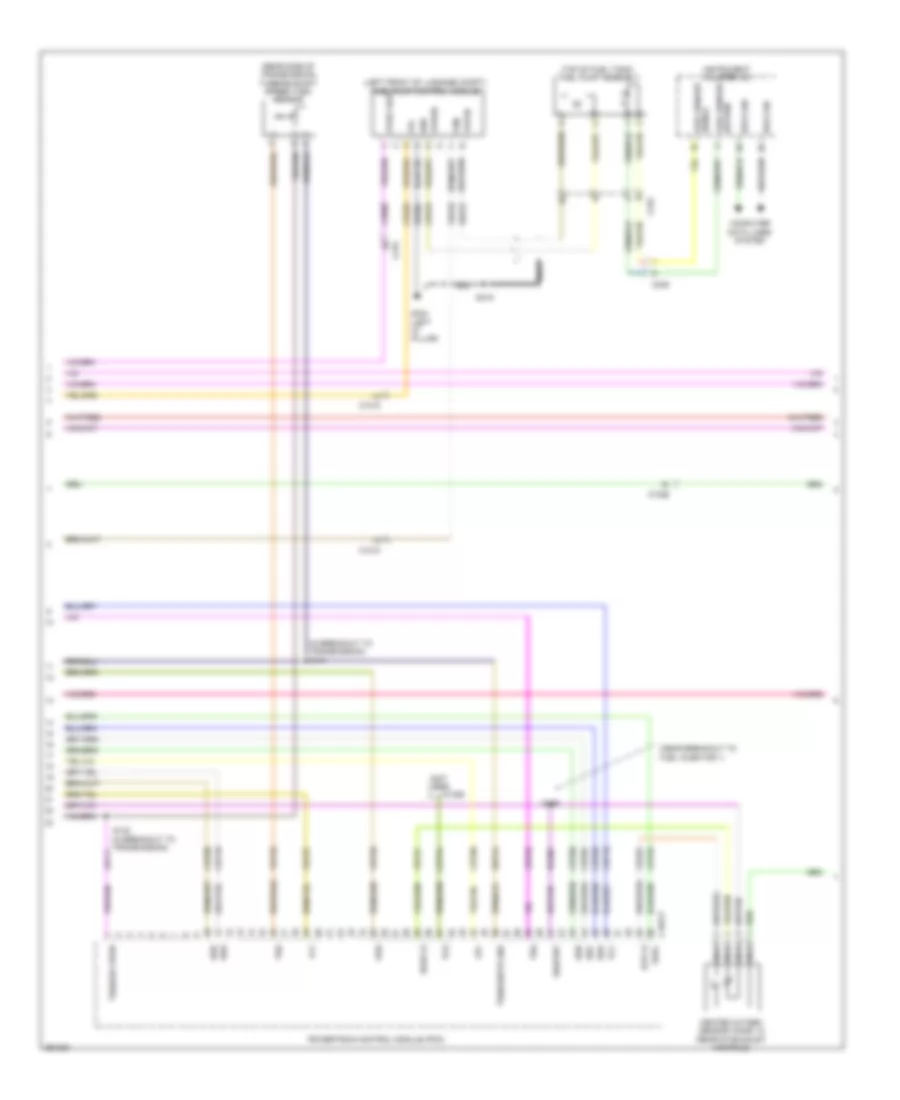
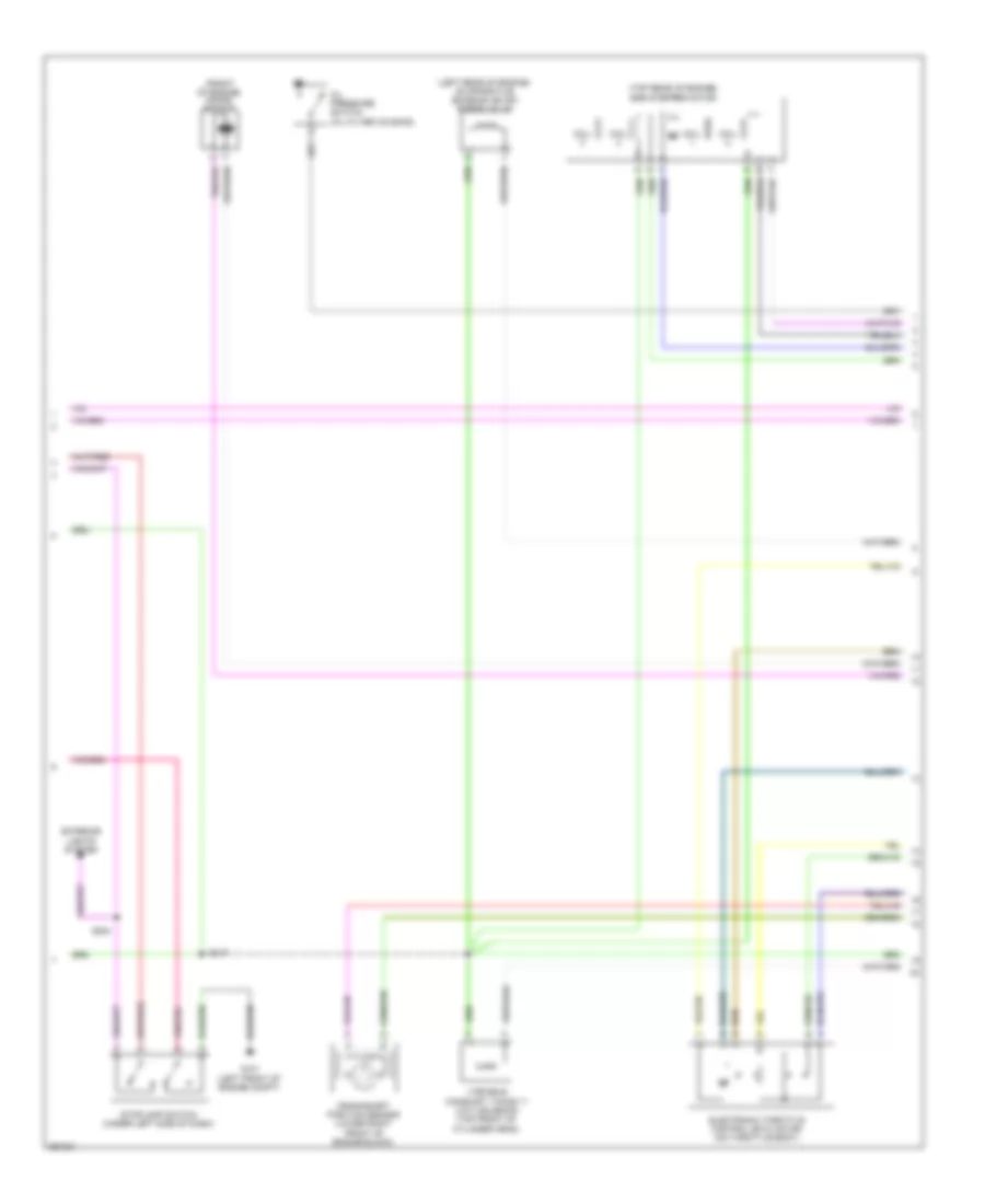
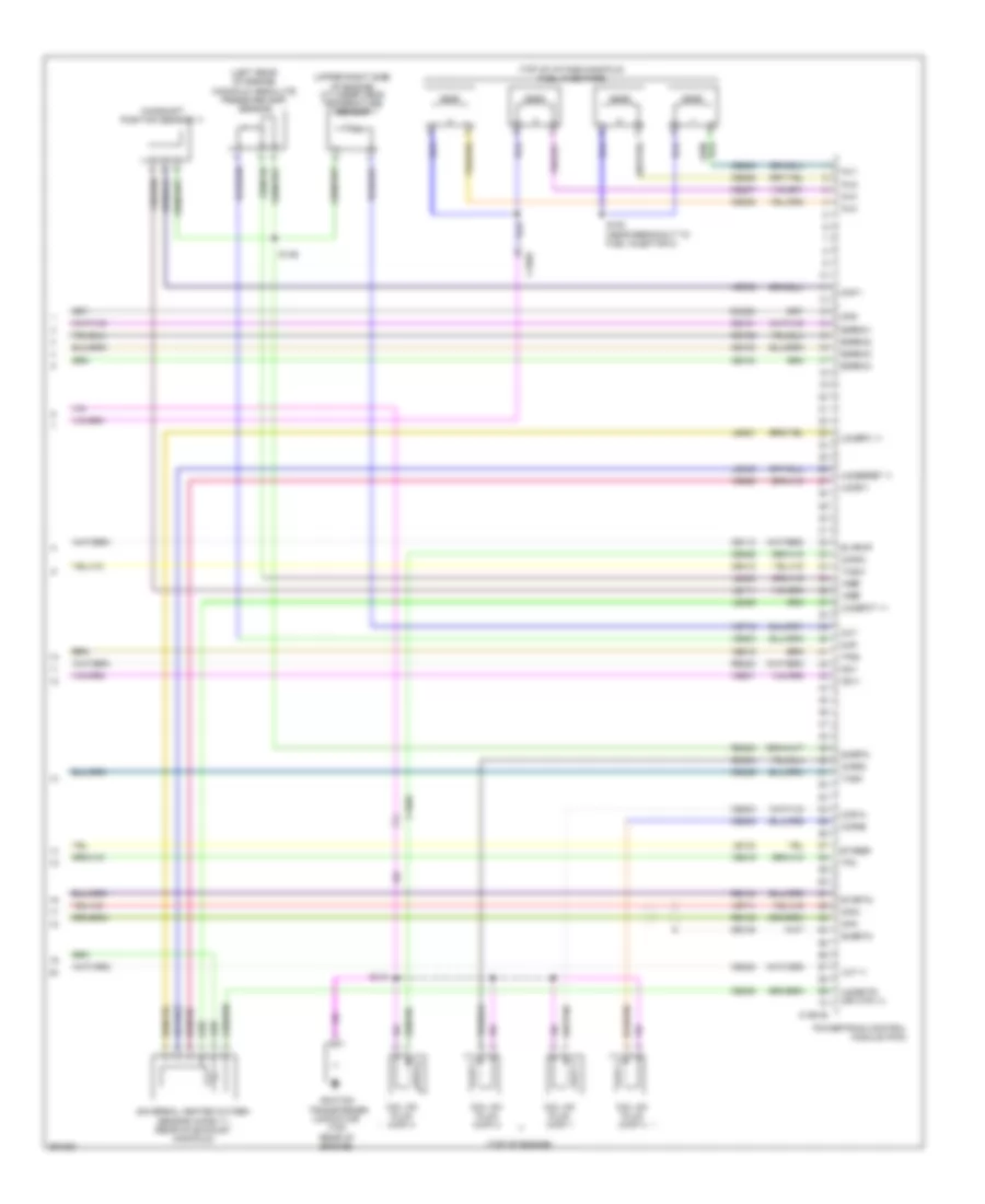
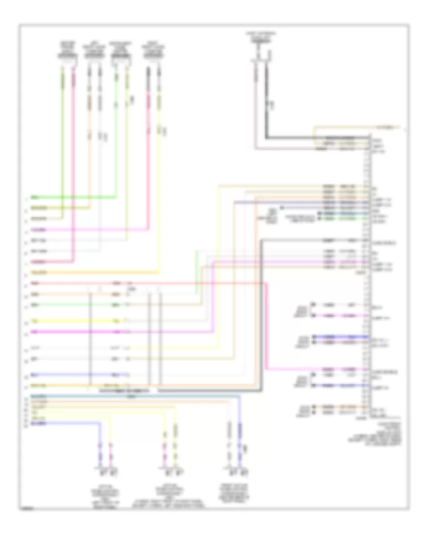
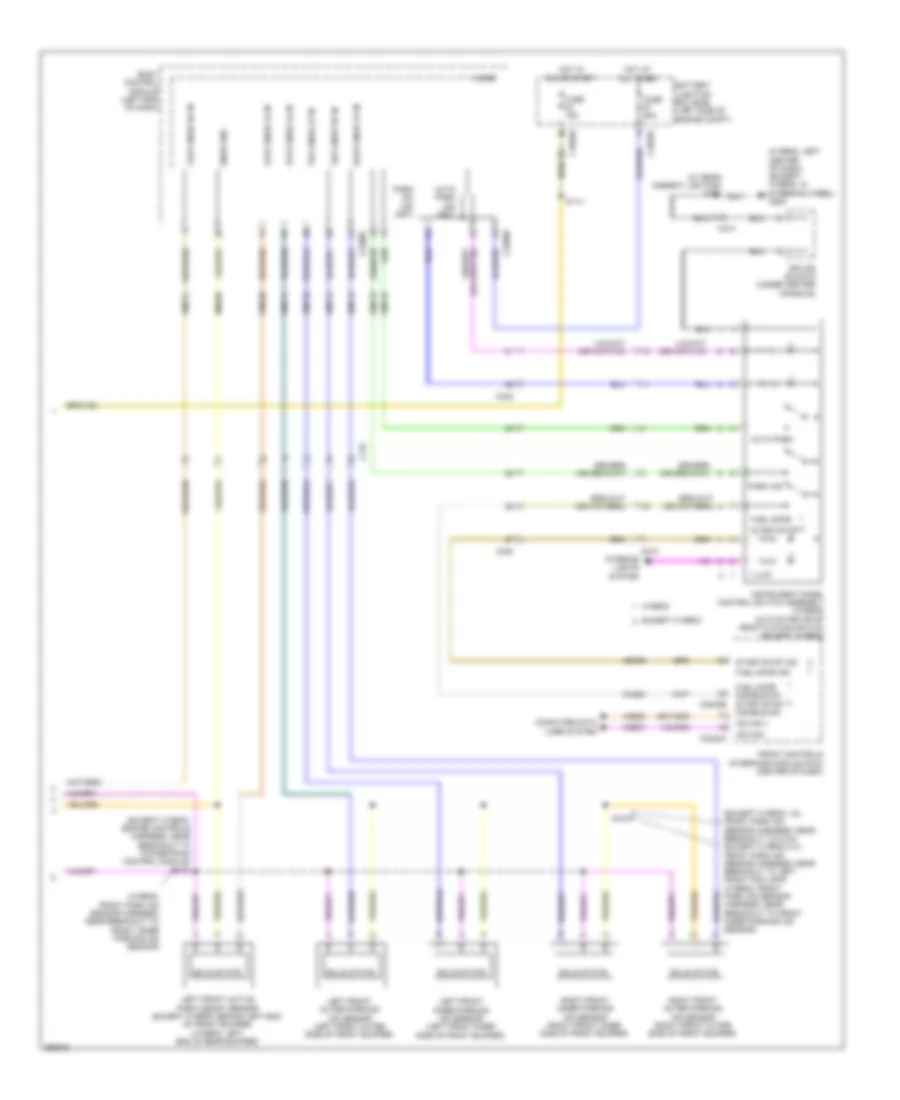
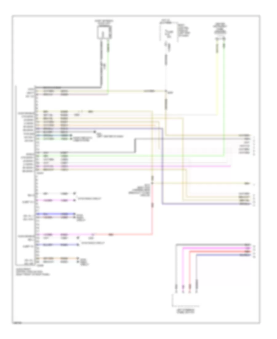
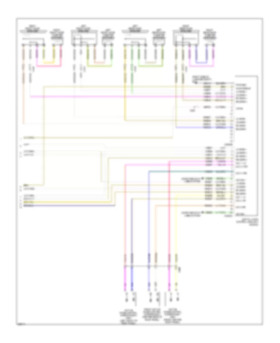
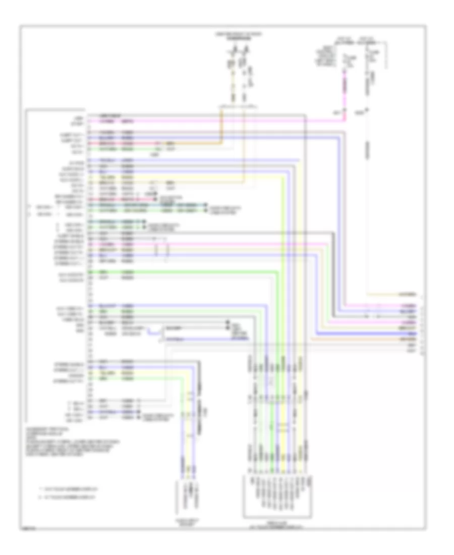
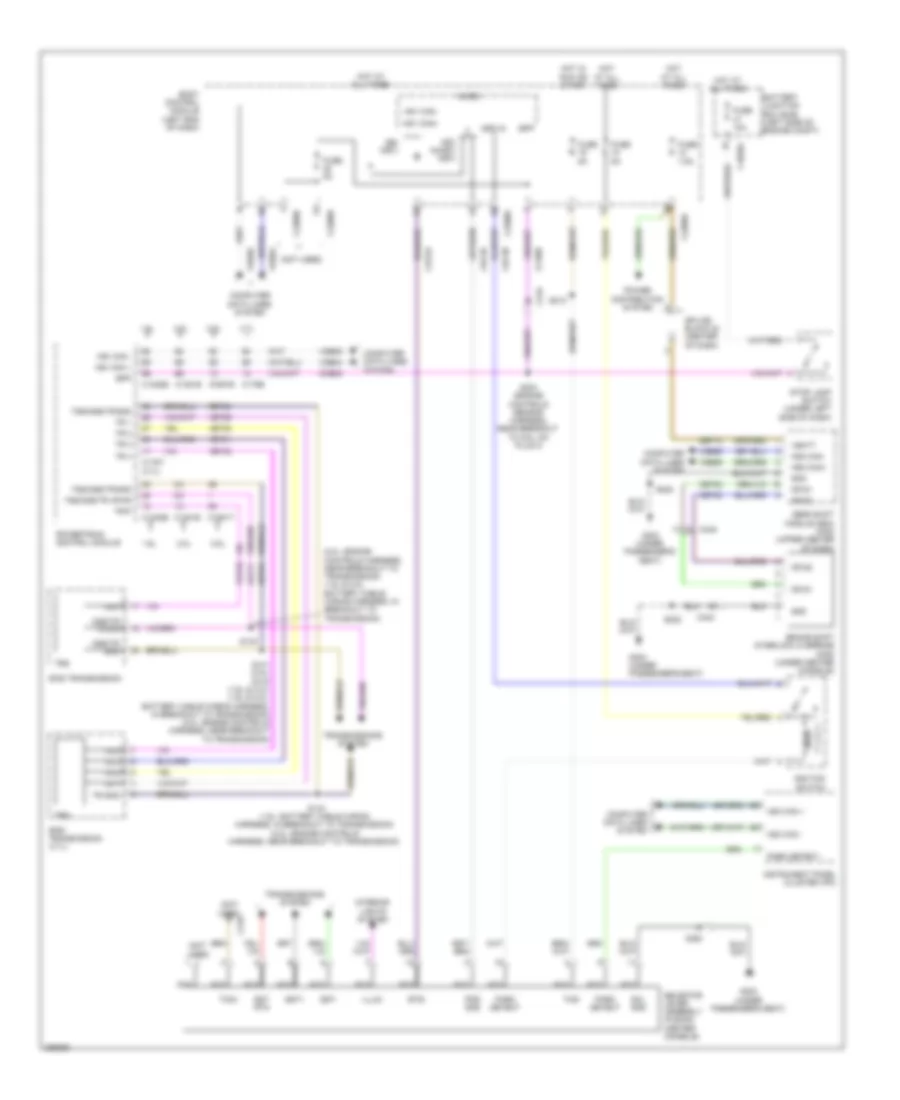
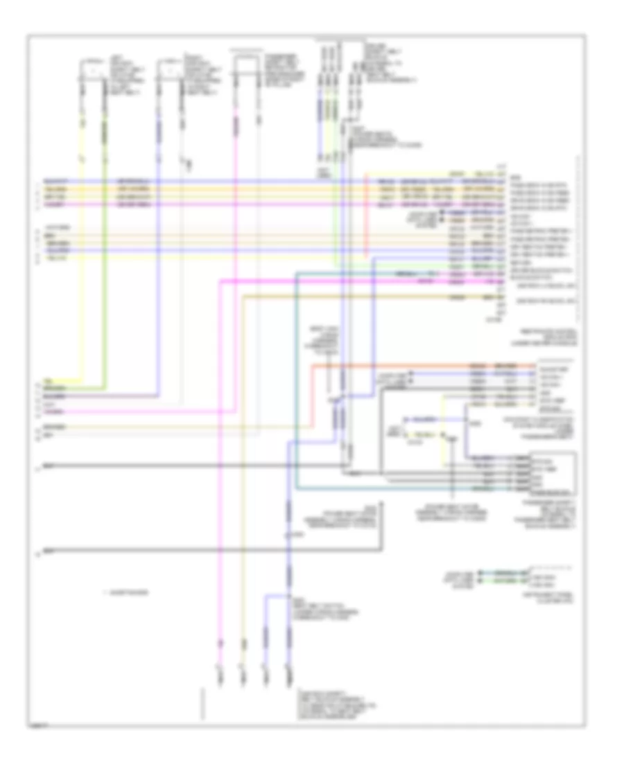
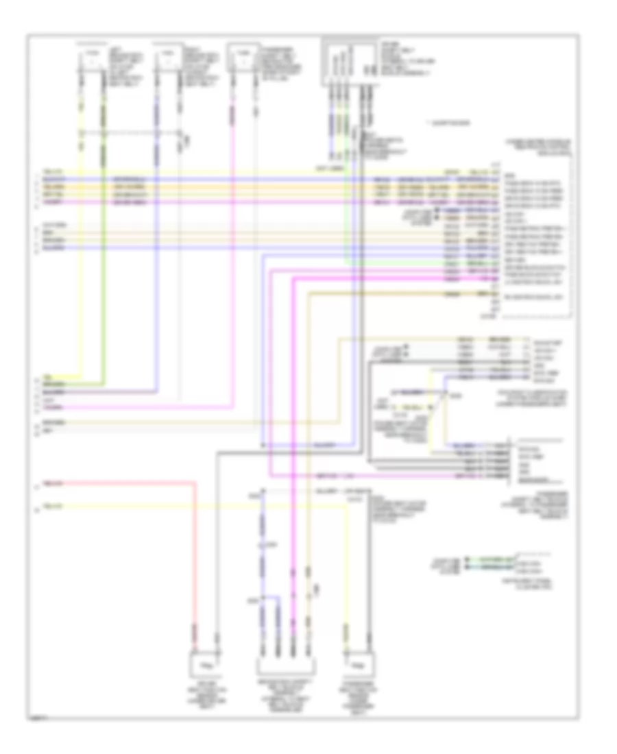
Automatic A/C Wiring Diagram, Except Hybrid (3 of 3) for Ford Fusion SE 2013
List of elements for Automatic A/C Wiring Diagram, Except Hybrid (3 of 3) for Ford Fusion SE 2013:
- (2.5l & 3.7l) s146
- (3.7l: engine controls harness, near breakout to coil on plug 3)
- (3.7l: top front of right cylinder bank)
- (engine controls sensor harness, near breakout to pcm)
- (left front of engine compt)
- (or re405)
- 1.6l turbo a/t
- 1.6l turbo m/t
- 2.0l flex fuel
- 2.5l
- 3.7l
- 87a
- A/c pressure transducer (right front of engine compt)
- Aat
- Accr
- Acpt
- Ambient air temperature sensor (behind right end of front grille)
- Battery junction box (bjb) (left side of engine compt)
- C1035a
- C1046
- C1232b
- C1232e
- C134
- C1381b
- C1381e
- C144
- C145
- C1551b
- C1551e
- C175b
- C175e
- Ce202
- Cec01
- Ch302
- Ch307
- Cht
- Computer data lines system
- Cooling fan motor 1 (behind left side of radiator)
- Cooling fan motor 2 (behind right side of radiator)
- Cpc
- Cylinder head temperature (cht) sensor (2.0l: upper right side of engine)
- Ect
- Engine controls system
- Engine coolant temperature (ect) sensor (1.6l turbo & 2.0l flex fuel) (right rear of cylinder head)
- Engine cooling fan high relay
- Engine cooling fan low relay
- Engine cooling fan relay
- Fuse 20a
- Fuse 30a
- G100
- G101 (left front of engine compt)
- Hfc
- Hot at all times
- Hot w/ pcm power relay energized
- Hs1 can +
- Hs1 can -
- Le424
- Lfc
- Lin
- Powertrain control module (pcm)
- Re405
- Re407
- Re454
- S126 (engine controls sensor harness, near breakout to coil on plug 3)
- S133
- S149 (2.0l & 1.6l turbo)
- Sig rtn
- Vacc
- Vdb04
- Vdb05
- Vdn06
- Ve462
- Ve712
- Ve716
- Ve750
- Vh433
- Vref
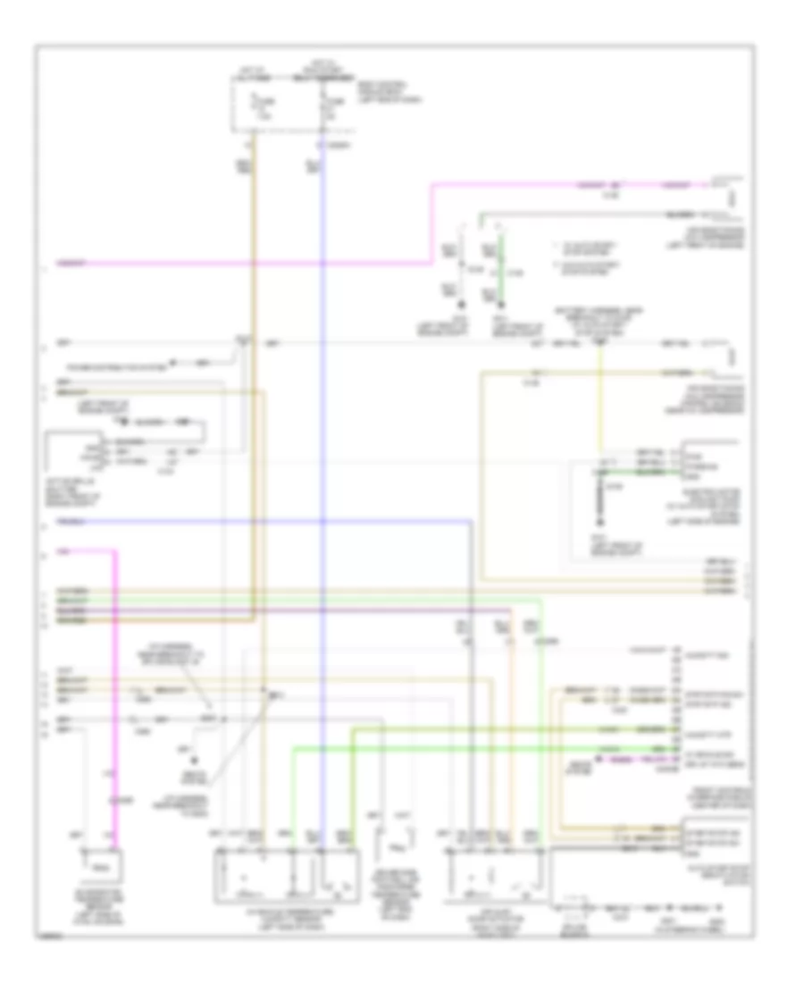
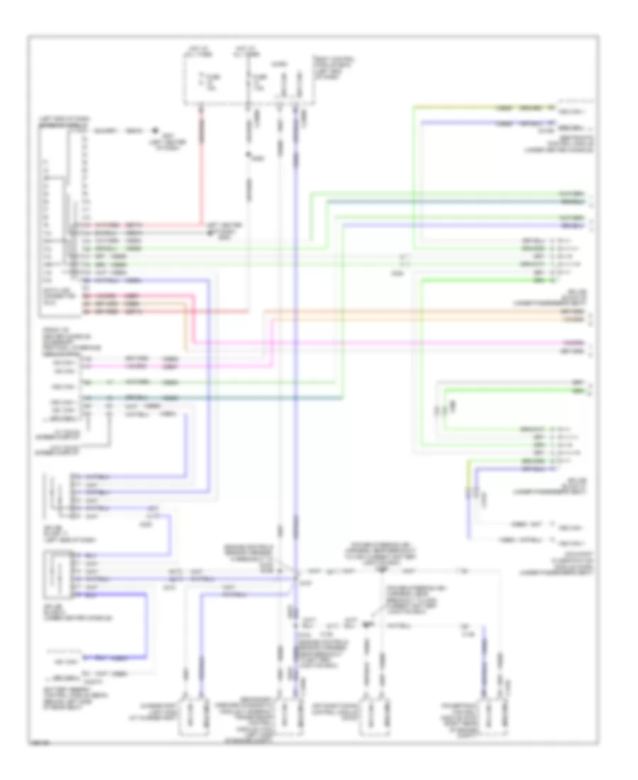
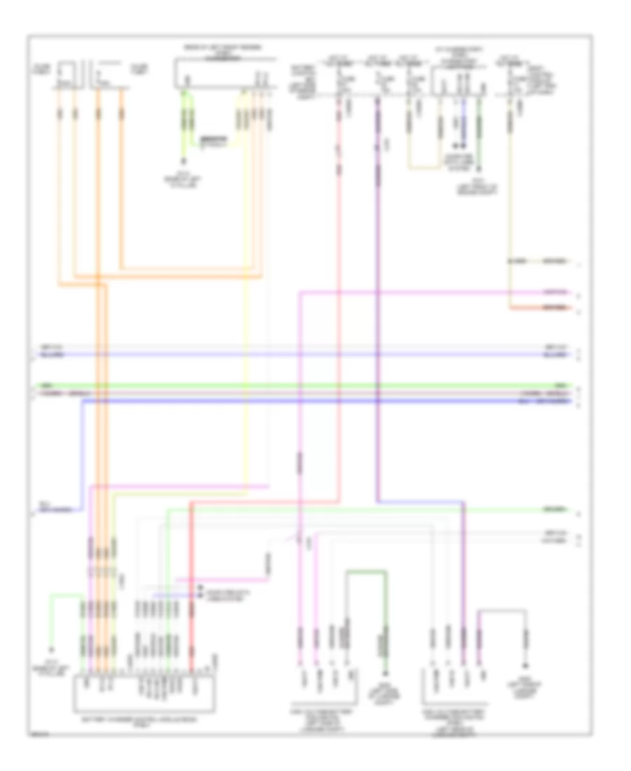
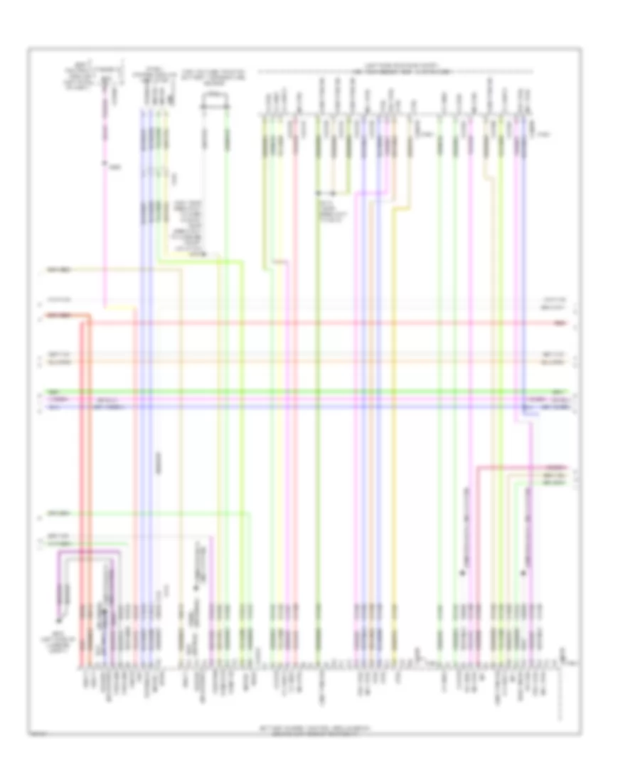
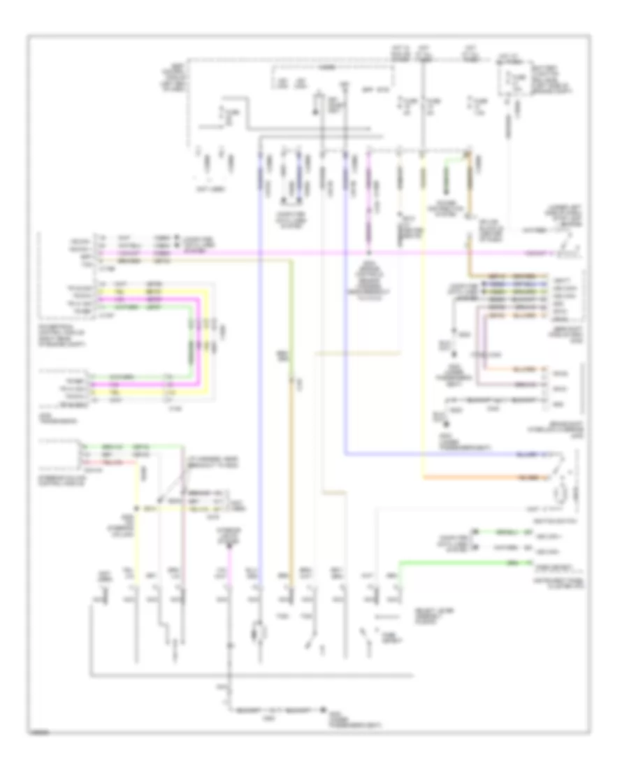
Automatic A/C Wiring Diagram, Hybrid (1 of 3) for Ford Fusion SE 2013
List of elements for Automatic A/C Wiring Diagram, Hybrid (1 of 3) for Ford Fusion SE 2013:
- (a/c jumper harness, near breakout to blower motor)
- (or vh410)
- (right side of dash)
- (right side of dash) g202
- (right side of hvac housing) blower motor
- 40a
- Battery junction box (bjb) (left side of engine compt)
- Blower control
- Blower motor control module (right side of hvac housing)
- Blower motor relay
- Blower relay
- C1035a
- C1035b
- C219
- C2402a
- C2402b
- C265
- C268
- C297a
- C297b
- Ch123
- Ch201
- Ch202
- Ch203
- Ch206
- Ch207
- Ch208
- Ch211
- Ch212
- Ch213
- Ch237
- Ch238
- Ch239
- Ch402
- Chs02
- Chs07
- Computer data lines system
- Crd02
- Defogger system
- Defrost request
- Defrost/panel/ floor mode door actuator
- Driver temperature blend door actuator
- Drv frt snsr 1 (or drv frt snsr 2)
- Drv frt snsr 1 drv frt snsr
- Drv heater feed
- Evap
- Feedback
- Front control interface module (center of dash)
- Fuse
- Fuse 10a
- Fuse 15a
- Fuse 20a
- Fusion
- G101 (left front of engine compt)
- G202
- Gd216
- Gnd
- Hot at all times
- Hot w/ pcm power relay energized
- Lh111
- Mkz
- Motor+
- Motor-
- Ms can+
- Ms can-
- Pass frt snsr 1
- Pass frt snsr 2
- Pass heater feed
- Pass st ntc sens
- Passenger temperature blend door actuator
- Red
- Rh111
- Rh301
- Rhs10
- S202
- S203 (a/c jumper harness, near breakout to blower motor)
- S210
- Sbb65
- Sbp12
- Seats system seats system
- Sig rtn
- Tcm power relay
- Vbatt
- Vdb06
- Vdb07
- Vh101
- Vh301
- Vh406
- Vh409
- Vh410 (or vh409)
- Vh411 (or vh412)
- Vh412 (or vh411)
- Vref
- W/ heated seats
Automatic A/C Wiring Diagram, Hybrid (2 of 3) for Ford Fusion SE 2013
List of elements for Automatic A/C Wiring Diagram, Hybrid (2 of 3) for Ford Fusion SE 2013:
- (fusion: i/p harness, near breakout to g202) (mkz: i/p harness, near breakout to driver knee airbag)
- (fusion: i/p harness, near breakout to splice block 19) (mkz: i/p harness, near breakout to i/p speaker)
- (not used)
- Air inlet mode door actuator (right side of hvac housing)
- Autolamp sensor input
- Autolamp sensor return
- Autolamp/sunload sensor (mkz: top left side of dash)
- Body control module (bcm) (left end of dash)
- C2280b
- C2280g
- C2280h
- C2402b
- C248
- C265
- C3047
- Center register air discharge temperature sensor
- Computer data lines system
- Driver side footwell air discharge temperature sensor
- Drv st ntc sens
- Drv sunload
- Evaporator temperature sensor
- Front control interface module (center of dash)
- Fuse 5a
- Fuse 7.5a
- Fusion
- Hot at all times
- Hot w/ run/ start relay energized
- Hs1 can+
- Hs1 can-
- Humidity mtr
- Humidity sig
- In vehicle sig
- In-vehicle temperature/ humidity sensor (left side of dash)
- Micro
- Mkz
- Pass sunload
- Passenger side center register air discharge temperature sensor
- Passenger side footwell air discharge temperature sensor
- Rhs05
- Rlf14
- S207
- S213
- S219 (mkz)
- Seats system
- Splice block 22
- Vdb04
- Vdb05
- Vh413
- Vh414
- Vh416
- Vh417
- Vha31
- Vlf14
Automatic A/C Wiring Diagram, Hybrid (3 of 3) for Ford Fusion SE 2013
List of elements for Automatic A/C Wiring Diagram, Hybrid (3 of 3) for Ford Fusion SE 2013:
- (engine controls sensor harness, near breakout to g100)
- (left front of engine compt)
- (left front of engine compt) g101
- (right front of engine compt) g106
- (right side of engine compt)
- (top center of cylinder head)
- A/c pressure transducer (right front of engine compt)
- Aat
- Acpt
- Active grille shutter (behind right end of grille)
- Air conditioning control module (accm)
- Ambient air temperature sensor (behind right end of front grille)
- Battery energy control module (becm) (behind left side of rear seat)
- Battery junction box (bjb) (left side of engine compt)
- C1026
- C1035a
- C134
- C145
- C1458a
- C1458f
- C146
- C1617k
- C175b
- C175e
- C1815a
- C1815b
- C1815c
- C4000
- C4002
- C4816b
- Cabin coolant heater (phev)
- Cabin heater coolant diverter valve (phev)
- Cabin heater coolant pump (phev)
- Cbb54
- Ce167
- Ce316
- Ch307
- Chp01
- Cht
- Computer data lines system
- Cooling fan motor (behind radiator)
- Cyb03
- Cylinder head temperature (ect)
- Ect2
- Electric motor coolant pump
- Engine controls system
- Engine coolant temperature (ect) sensor 2 (phev)
- Engine cooling fan relay
- Ev hs can+
- Ev hs can-
- Fcv
- Fuse 20a
- Fuse 275a
- Fuse 30a
- G100
- G105
- G107
- Gd113
- Gnd
- Hcso
- High current battery junction box (bjb)
- High voltage battery service disconnect
- Hot at all times
- Hot w/ pcm power relay energized
- Hs can +
- Hs can -
- Hv+
- Hv-
- Le423
- Lin
- Powertrain control module (right rear of engine compt)
- Pwm
- Re141
- Re405
- Re407
- S101
- S108
- S110
- S115
- S145
- Secondary on board diagnostic module (sobdmc)/ transmission control module (tcm) (left side of engine compt)
- Sig rtn
- Sigrtn
- Tcmrc
- Vbatt
- Vdb04
- Vdb05
- Vdn06
- Ve712
- Ve716
- Ve750
- Vec03
- Verf
- Vh433
- Vpwr
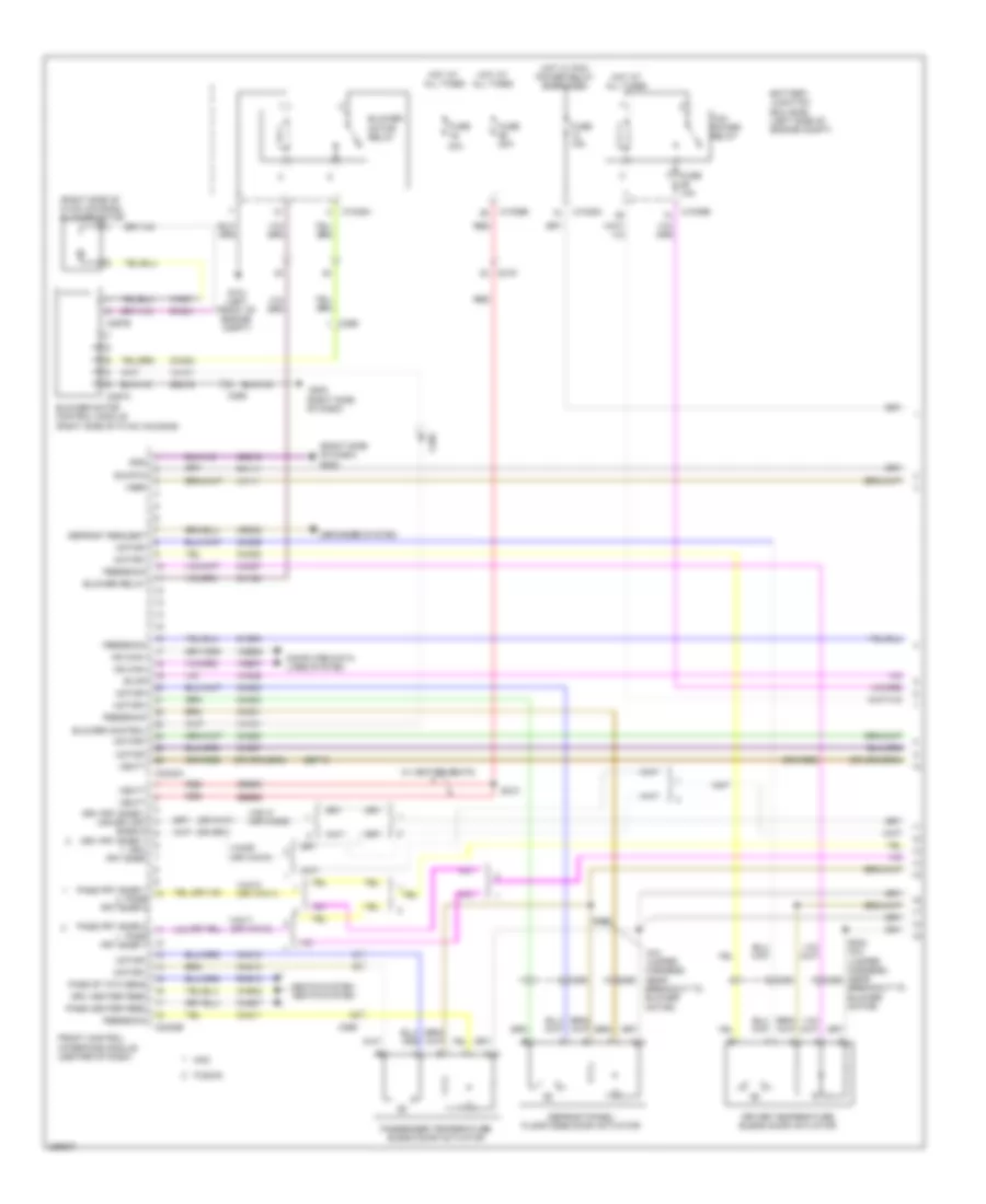
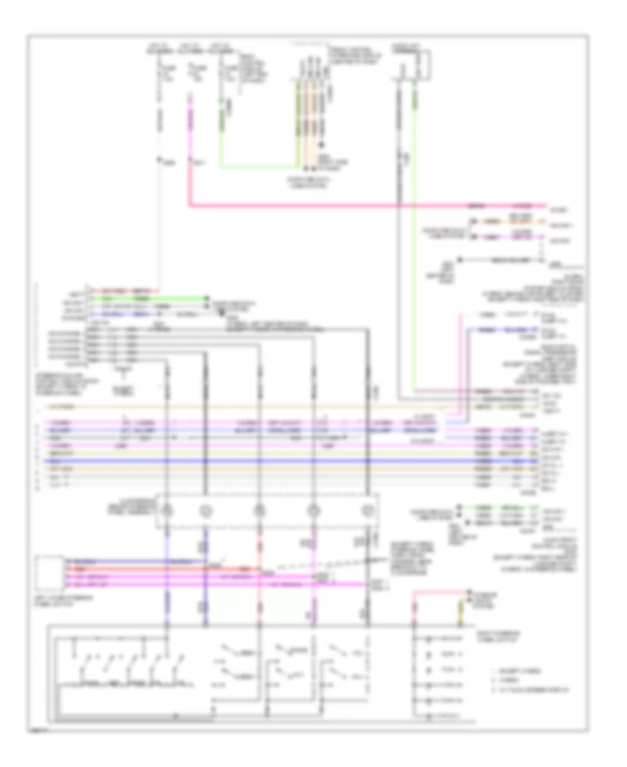
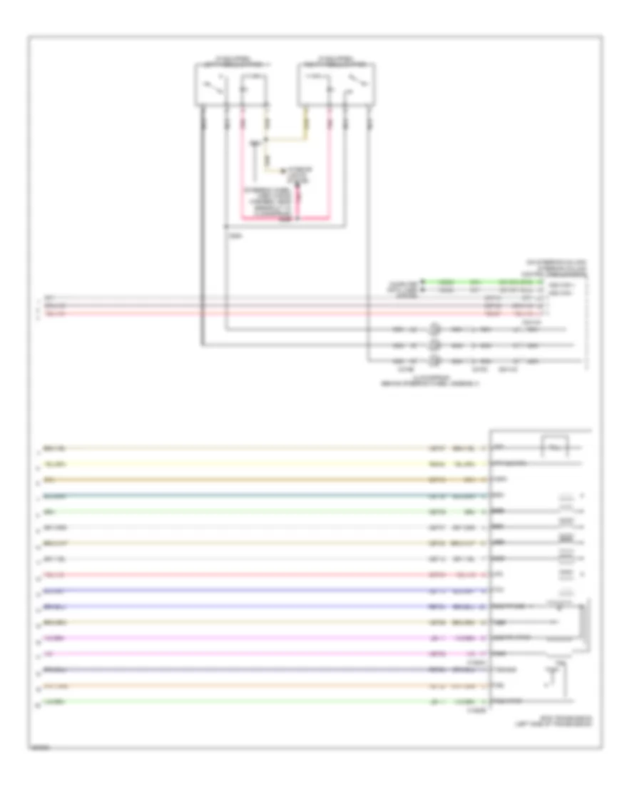
Manual A/C Wiring Diagram (1 of 3) for Ford Fusion SE 2013
List of elements for Manual A/C Wiring Diagram (1 of 3) for Ford Fusion SE 2013:
- (a/c jumper harness, near breakout to blower motor)
- (right side of dash) g202
- (right side of hvac unit) blower motor
- 40a
- A/c clutch relay
- Air distribution door actuator (left side of hvac unit)
- Battery junction box (bjb) (left side of engine compt)
- Blower control
- Blower motor control module (right side of hvac unit)
- Blower motor relay
- Blower relay
- C1035a
- C219
- C2402a
- C2402b
- C265
- C268
- C297a
- C297b
- Ch123
- Ch201
- Ch202
- Ch203
- Ch206
- Ch207
- Ch208
- Ch211
- Ch212
- Ch213
- Ch402
- Chs02
- Chs07
- Computer data lines system
- Crd02
- Defogger system
- Defrost request
- Drv frnt snsr
- Drv heater feed
- Evap
- Feedback
- Front controls interface module (center of dash)
- Fuse
- Fuse 10a
- Fuse 15a
- G101 (left front of engine compt)
- Gd216
- Gnd
- Hot at all times
- Hot w/ pcm power relay energized
- Lh111
- Motor+
- Motor-
- Ms can+
- Ms can-
- Pass heater feed
- Pass st ntc sens
- Passenger temperature door actuator (right side of hvac unit)
- Rh111
- Rh301
- Rhs10
- S202
- S203 (a/c jumper harness, near breakout to blower motor)
- Sbp12
- Seats system
- Sig rtn
- Vbatt
- Vdb06
- Vdb07
- Vh101
- Vh301
- Vh406
- Vh409
- Vref
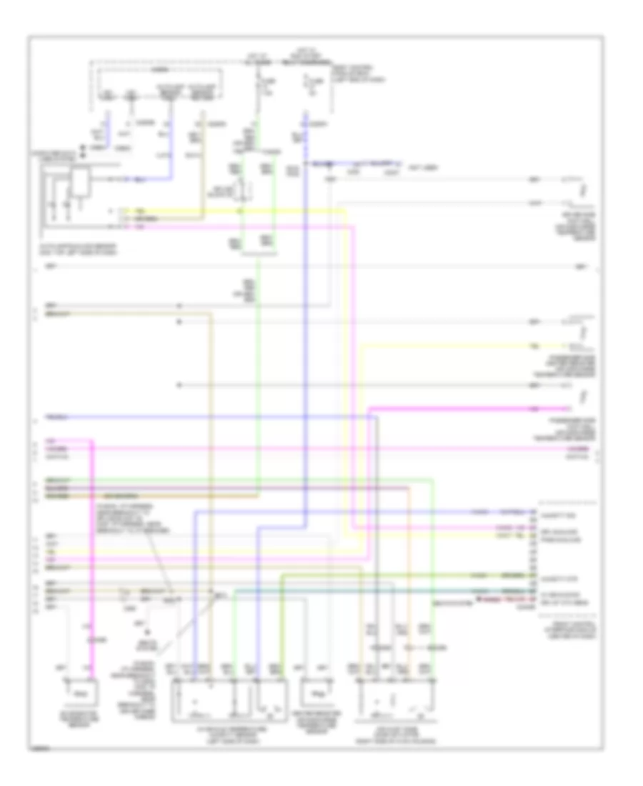
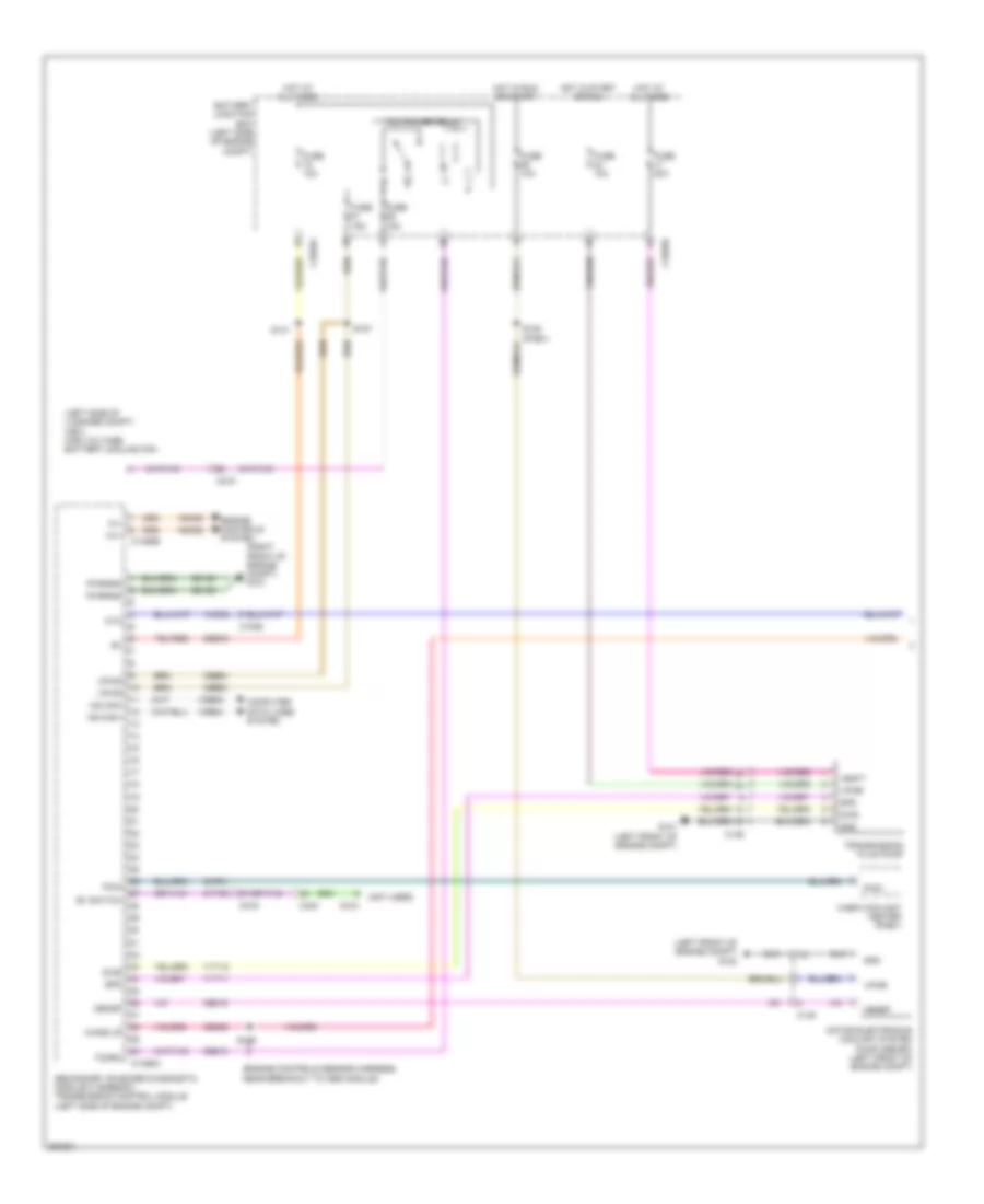
Manual A/C Wiring Diagram (2 of 3) for Ford Fusion SE 2013
List of elements for Manual A/C Wiring Diagram (2 of 3) for Ford Fusion SE 2013:
- (battery harness, near breakout to g109) (w/ auto start/ stop system) s140
- (i/p harness, near breakout to g202)
- (i/p harness, near breakout to splice block 19)
- (left front of engine compt)
- (right side of hvac unit)
- Active grille shutter (right front of engine compt)
- Air conditioning (a/c) compressor (left front of engine)
- Air conditioning (a/c) compressor control solenoid (near a/c compressor)
- Air inlet door actuator
- Auto start/stop deactivation switch
- Body control module (bcm) (left end of dash)
- C134
- C146
- C210
- C2280h
- C2402b
- C265
- C340
- Ch253
- Ch469
- Driver side footwell air discharge temperature sensor (left end of dash)
- Drv st ntc sens
- Electric motor coolant pump (w/ auto start/stop system) (left side of engine)
- Evaporator temperature sensor (left side of hvac housing)
- Front controls interface module (center of dash)
- Fuse 5a
- Fuse 7.5a
- G101 (left front of engine compt)
- G200 (in steering wheel)
- Gnd
- Hot at all times
- Hot w/ run/ start relay energized
- Humidity mtr
- Humidity sig
- In vehicle sig
- In-vehicle temperature/ humidity sensor (left side of dash)
- Lin
- Power distribution system
- Pwr
- Pwr/diag
- Rhs05
- S101
- S110
- S139
- S207
- S213
- S301
- Seats system
- Splice block 6
- Start/stop ind
- Start/stop sw
- Strt/stp dis sw
- Strt/stp ind
- Vh413
- Vh414
- Vha31
- Vpwr
- W/ auto start/ stop system
- W/o auto start/ stop system
Manual A/C Wiring Diagram (3 of 3) for Ford Fusion SE 2013
List of elements for Manual A/C Wiring Diagram (3 of 3) for Ford Fusion SE 2013:
- (2.5l) s146
- (engine controls sensor harness, near breakout to pcm)
- (left front of engine compt)
- (or re405)
- 1.6l turbo a/t
- 1.6l turbo m/t
- 2.0l flex fuel
- 2.5l
- 87a
- A/c pressure transducer (right front of engine compt)
- Aat
- Accr
- Acpt
- Ambient air temperature sensor (behind right end of front grille)
- Battery junction box (bjb) (left side of engine compt)
- C1035a
- C1232b
- C1232e
- C134
- C1381b
- C1381e
- C144
- C145
- C1551b
- C1551e
- Ce202
- Cec01
- Ch302
- Ch307
- Cht
- Computer data lines system
- Cooling fan motor 1 (behind radiator)
- Cooling fan motor 2 (behind radiator)
- Cpc
- Cylinder head temperature (cht) sensor (2.0l flex fuel & 2.5l) (2.0l flex fuel: upper right side of engine)
- Ect
- Engine controls system
- Engine coolant temperature (ect) sensor (1.6l turbo & 2.0l flex fuel) (right rear of cylinder head)
- Engine cooling fan high relay
- Engine cooling fan low relay
- Engine cooling fan relay
- Fuse 20a
- Fuse 30a
- G100
- G101 (left front of engine compt)
- Hfc
- Hot at all times
- Hot w/ pcm power relay energized
- Hs1 can +
- Hs1 can -
- Le424
- Lfc
- Lin
- Near breakout to knock sensor 2) (2.0l: engine controls harness, near breakout to manifold absolute pressure sensor)
- Powertrain control module (pcm) (right rear of engine compt)
- Re405
- Re407
- Re454
- S126 (engine controls sensor harness, near breakout to coil on plug 3)
- S133
- Sig rtn
- Vacc
- Vdb04
- Vdb05
- Vdn06
- Ve462
- Ve712
- Ve716
- Ve750
- Vh433
- Vref
ANTI-LOCK BRAKES
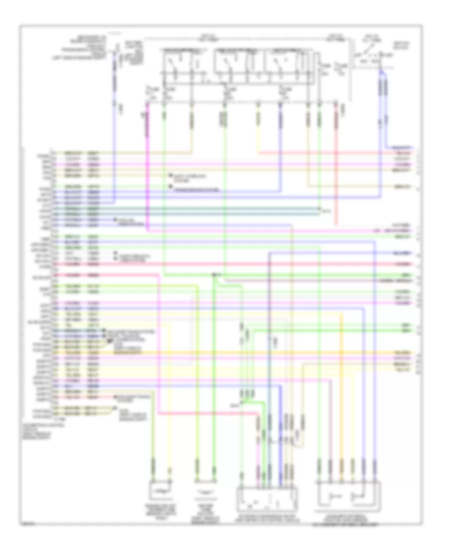
Anti-lock Brakes Wiring Diagram, Except Hybrid (1 of 2) for Ford Fusion SE 2013
List of elements for Anti-lock Brakes Wiring Diagram, Except Hybrid (1 of 2) for Ford Fusion SE 2013:
- Anti-lock brake system (abs) module (left rear of engine compt)
- Battery junction box (bjb) (left side of engine compt)
- Brake booster vacuum sensor (on brake booster)
- C1010
- C1035a
- C192
- C215
- C219
- C3050
- C3134
- C340
- Cbb25
- Ccb16
- Ccb17
- Ccb18
- Ccb19
- Ccb20
- Ccb21
- Ccb22
- Ccb23
- Ccb24
- Ccb25
- Computer data lines system
- Ebp sw1
- Ebp sw2
- Ebp sw3
- Ebp sw4
- Ebp sw5
- Ebp sw6
- Fuse 10a
- Fuse 30a
- Fuse 60a
- Fusion
- G102 (left front of engine compt)
- Gd121
- Gnd
- Hot at all times
- Hot in start or run
- Hs2 can+
- Hs2 can-
- Ign
- Lca37
- Left front wheel speed sensor (left front hub assembly)
- Left parking brake actuator motor (in left rear wheelwell)
- Left rear wheel speed sensor (left rear hub assembly)
- Lf sensor hi
- Lf sensor lo
- Lr sensor hi
- Lr sensor lo
- Mtr a epb lt
- Mtr a epb rt
- Mtr b epb lt
- Mtr b epb rt
- Nca
- Rca17
- Rca18
- Rca19
- Rca20
- Rca37
- Rf sensor hi
- Rf sensor lo
- Right front wheel speed sensor (right front hub assembly)
- Right parking brake actuator motor (in right rear wheelwell)
- Right rear wheel speed sensor (right rear hub assembly)
- Rr sensor hi
- Rr sensor lo
- Sbb69
- Sbb82
- Vac gnd
- Vac sense p
- Vac sig
- Vbatt
- Vca03
- Vca04
- Vca05
- Vca06
- Vca38
- Vdb25
- Vdb26
Anti-lock Brakes Wiring Diagram, Except Hybrid (2 of 2) for Ford Fusion SE 2013
List of elements for Anti-lock Brakes Wiring Diagram, Except Hybrid (2 of 2) for Ford Fusion SE 2013:
- (engine controls sensor harness, near breakout to coil on plug 3)
- 1.6l
- 2.0l
- 2.5l
- 3.7l
- Battery junction box (bjb) (left side of engine compt)
- Body control module (bcm) (left end of dash)
- Bpp
- Bps
- C1035a
- C1232b
- C1381b
- C1551b
- C175b
- C210
- C219
- C2280b
- C2280h
- Ccb08
- Ces09
- Computer data lines system
- Fuse 10a
- Fusion
- G101 (left front of engine compt)
- Hot at all times
- Hs1 can +
- Hs1 can -
- Hs1 can+
- Hs1 can-
- Hs3 can+
- Hs3 can-
- Instrument panel cluster (ipc)
- Interior lights system
- Micro
- Parking brake switch (foot pedal: left kick panel) (hand lever: under center console)
- Powertrain control module (pcm)
- S204
- Stop lp sw
- Stoplamp switch (under left side of dash)
- Sw1
- Sw2
- Sw3
- Sw4
- Sw5
- Sw6
- Vdb04
- Vdb05
Anti-lock Brakes Wiring Diagram, Hybrid (1 of 2) for Ford Fusion SE 2013
List of elements for Anti-lock Brakes Wiring Diagram, Hybrid (1 of 2) for Ford Fusion SE 2013:
- (on brake pedal assembly) brake pedal angle sensor
- Anti-lock brake system (abs) module (left rear of engine compt)
- Battery junction box (bjb) (left side of engine compt)
- Brake booster vacuum sensor
- Bst pwm
- Bst pwr
- C1010
- C1035a
- C192
- C215
- C219
- C3050
- C3134
- C340
- Cbb25
- Cbb45
- Cca22
- Ccb16
- Ccb17
- Ccb18
- Ccb19
- Ccb20
- Ccb21
- Ccb22
- Ccb23
- Ccb24
- Ccb25
- Ccb30
- Ccb33
- Ccb41
- Computer data lines system
- Ebp sw1
- Ebp sw2
- Ebp sw3
- Ebp sw4
- Ebp sw5
- Ebp sw6
- Fuse 10a
- Fuse 30a
- Fuse 60a
- Fusion
- G102 (left front of engine compt)
- Gd121
- Gnd
- Hot at all times
- Hot in start or run
- Hs2 can+
- Hs2 can-
- Ign
- Lca27
- Lca37
- Left front wheel speed sensor (left front hub assembly)
- Left parking brake actuator motor (on left rear wheel hub assembly)
- Left rear wheel speed sensor (left rear hub assembly)
- Lf sensor hi
- Lf sensor lo
- Lr sensor hi
- Lr sensor lo
- Mp gnd
- Mp sense
- Mp sig
- Mtr a epb lt
- Mtr a epb rt
- Mtr b epb lt
- Mtr b epb rt
- Nca
- Pas gnd
- Pas sensep
- Pas sig 1
- Pas sig 2
- Rca17
- Rca18
- Rca19
- Rca20
- Rca27
- Rca37
- Rcb33
- Rf sensor hi
- Rf sensor lo
- Right front wheel speed sensor (right front hub assembly)
- Right parking brake actuator motor (on right rear wheel hub assembly)
- Right rear wheel speed sensor (right rear hub assembly)
- Rr sensor hi
- Rr sensor lo
- Sbb69
- Sbb82
- Vac pump
- Vac pump mon
- Vac sen gnd
- Vac sen sig
- Vac sense pwr
- Vacrc
- Vbatt
- Vca03
- Vca04
- Vca05
- Vca06
- Vca22
- Vca30
- Vca38
- Vca43
- Vcb34
- Vdb25
- Vdb26
Anti-lock Brakes Wiring Diagram, Hybrid (2 of 2) for Ford Fusion SE 2013
List of elements for Anti-lock Brakes Wiring Diagram, Hybrid (2 of 2) for Ford Fusion SE 2013:
- Battery junction box (bjb) (left side of engine compt)
- Body control module (bcm) (left end of dash)
- Bpp
- Bps
- Brake booster solenoid (left rear of engine compt)
- Brake booster travel sensor (on brake booster)
- Bst pwm
- Bst pwr
- C1035a
- C146
- C175b
- C210
- C219
- C2280b
- C2280h
- Ccb08
- Ces09
- Cluster (ipc)
- Computer
- Computer data lines system
- Data lines
- Fuse 10a
- Fuse 40a
- Fuse 5a
- Fusion
- G101 (left front of engine compt)
- Hot at all times
- Hot in start or run
- Hs1 can +
- Hs1 can -
- Hs1 can+
- Hs1 can-
- Hs3 can+
- Hs3 can-
- Instrument panel
- Interior lights system
- Micro
- Parking brake switch (foot pedal: left kick panel) (hand lever: under center console)
- Powertrain control module (pcm) (right rear of engine compt)
- Re406
- S204 (engine controls sensor harness, near breakout to c1010)
- Sigrtn
- Stop lp sw
- Stoplamp switch (under left side of dash)
- Sw1
- Sw2
- Sw3
- Sw4
- Sw5
- Sw6
- System
- Vacuum pump cut-off relay
- Vacuum pump motor
- Vacuum pump relay
- Vdb04
- Vdb05
ANTI-THEFT
Forced Entry Wiring Diagram (1 of 3) for Ford Fusion SE 2013
List of elements for Forced Entry Wiring Diagram (1 of 3) for Ford Fusion SE 2013:
- (except hybrid: near breakout to c215) s307
- (except hybrid: near breakout to driver safety belt anchor preten- sioner)
- 1/2
- 3/4
- 5/6
- 7/8
- 9/0
- A10
- Ajar
- Ajar sig
- Ajar sw sig
- Ant +
- Ant -
- B12
- B13
- B17
- B18
- B19
- B20
- B21
- Batt
- Body control module (bcm) (left end of dash)
- C133
- C134
- C2280c
- C2280d
- C2280e
- C2280f
- C2280g
- C311
- C312
- C313
- C314
- C406
- C4174b
- C700
- C800
- Compartment
- Computer data lines system
- Cpk28
- Cpk29
- Cpk30
- Cpk31
- Cpl25
- Cpl44
- Cpl81
- Except hybrid
- Ext1 ante- nna high
- Ext1 ante- nna low
- Ext2 ante- nna high
- Ext2 ante- nna low
- Fuse 10a
- Fuse 5a
- Fusion
- G101 (left front of engine compt)
- G302 (under driver's seat)
- G400 (left side of luggage compt)
- Gnd
- Half bridge
- Hood ajar
- Hood ajar switch (fusion: left front of engine compt) (mkz: center front of engine compt)
- Hot at all times
- Key- pad a
- Key- pad b
- Key- pad c
- Keyless entry keypad
- Keypad illum (fet)
- Left front exterior door handle
- Left rear exterior door handle
- Logic
- Luggage compartment ajar
- Luggage compartment lid latch (center rear of luggage compt lid)
- Micro
- Mkz
- Ms can+
- Ms can-
- Nca
- Prot- ect 1 ante- nna high
- Prot- ect 1 ante- nna low
- Prot- ect 2 ante- nna high
- Prot- ect 2 ante- nna low
- Rear gate trunk module (hybrid: left side of luggage compt)
- Right front exterior door handle
- Right rear exterior door handle
- Rpk01
- Rpk02
- Rpk06
- Rpk39
- S101
- S305
- S318 (mkz)
- S405
- Vbatt
- Vdb06
- Vdb07
- Vpk01
- Vpk02
- Vpk05
- Vpk06
- Vpk40
- Vpk46
- Vpk47
- Vpl56
- W/ power luggage
- W/o power luggage compartment
Forced Entry Wiring Diagram (2 of 3) for Ford Fusion SE 2013
List of elements for Forced Entry Wiring Diagram (2 of 3) for Ford Fusion SE 2013:
- (except hybrid: rear of right rear door) right rear door latch release motor
- (except hybrid: right side of luggage compt) radio transceiver module
- (left front door window regulator wiring harness, near breakout to left exterior mirror) (mkz) s502
- (not used)
- (rear corner of luggage compt) keyless entry rear antenna
- 1.6l & 2.5l
- 2.0l & 3.7l
- A11
- A16
- Ajar
- Ant +
- Ant -
- C1617f
- C1716f
- C311
- C313
- C314
- C340
- C72b
- C832
- C913
- Can+ ms
- Can- ms
- Computer data lines system
- Except hybrid
- Fusion
- G302 (under c248 driver's seat)
- G302 (under driver's seat)
- G303 (under passenger's seat)
- Gd382
- Gd383
- Gnd
- High current battery junction box (bjb) (except hybrid: left side of engine compt)
- Hot at all times
- Hybrid
- Interior lights system
- Internal antenna rke receiver
- K-line
- Latch gnd
- Left front door latch release motor (except hybrid: rear of left front door)
- Left rear door latch release motor (except hybrid: rear of left rear door)
- Left rear door module
- Lock un-
- Ltch gnd
- Mega fuse 125a
- Passive anti-theft
- Reset
- Right rear door module
- Rpl71
- Rpl72
- S700
- S800
- Sbp29
- Sbp30
- Sbp32
- Set
- System front antenna
- System interior lights
- Un- lock
- Vbatt
- Vdb06
- Vdb07
- Vpl56
Forced Entry Wiring Diagram (3 of 3) for Ford Fusion SE 2013
List of elements for Forced Entry Wiring Diagram (3 of 3) for Ford Fusion SE 2013:
- (except hybrid: body main wiring harness, near breakout to c291) s312
- (except hybrid: body main wiring harness, near breakout to left footwell lamp) (mkz) s234
- (hybrid: front of driver's door)
- (not used)
- (or cpl26)
- (under driver's seat)
- (under passenger's seat)
- A11
- A16
- Ajar
- Body control module (bcm) (left end of dash)
- C2280a
- C2280d
- C2280f
- C248
- C311
- C312
- C501a
- C501b
- C652a
- C652b
- Central lock relay
- Central unlock relay
- Computer data lines system
- Cpl11
- Cpl13
- Cpl15
- Cpl16
- Cpl25
- Cpl26
- Cpl28
- Cpl29
- Cpl30
- Cpl31
- Cpl36
- Cpl39
- Cpl42
- Cpl43
- Cpl51
- Cpl77
- Cpl87
- Cpl88
- Door status
- Driver door module (ddm)
- Driver/ fuel flap unlock relay
- Except hybrid
- Fuse 20a
- Fuse 30a
- G302
- G302 (under driver's seat)
- G303
- Gd382
- Gd383
- Gear shift module (mkz) (except hybrid: upper center of dash)
- Gnd
- Hot at all times
- Illum
- Interior lights system
- Lck status
- Led
- Left front door lock switch
- Lock
- Ltch gnd
- Micro
- Mkz fusion
- Ms can +
- Ms can -
- Ms can+
- Ms can-
- Passenger door module
- Pwr gnd
- Red
- Reset
- Reset/ulck
- Reset/unlock
- Right front door latch release motor (except hybrid: rear of right front door)
- Right front door lock switch
- Rpl61
- Rpl62
- Rpw03
- Rpw05
- Rtn
- S311 (except hybrid: body main wiring harness, near breakout to c291)
- S500
- S600
- Sbp25
- Sbp26
- Set
- Set/lck
- Set/lock
- Splice block 1 (driver's door)
- Splice block 2 (passenger's door)
- Un- lock
- Unlock
- Unlock switch
- Vbatt
- Vdb06
- Vdb07
- W/ memory
- W/o memory
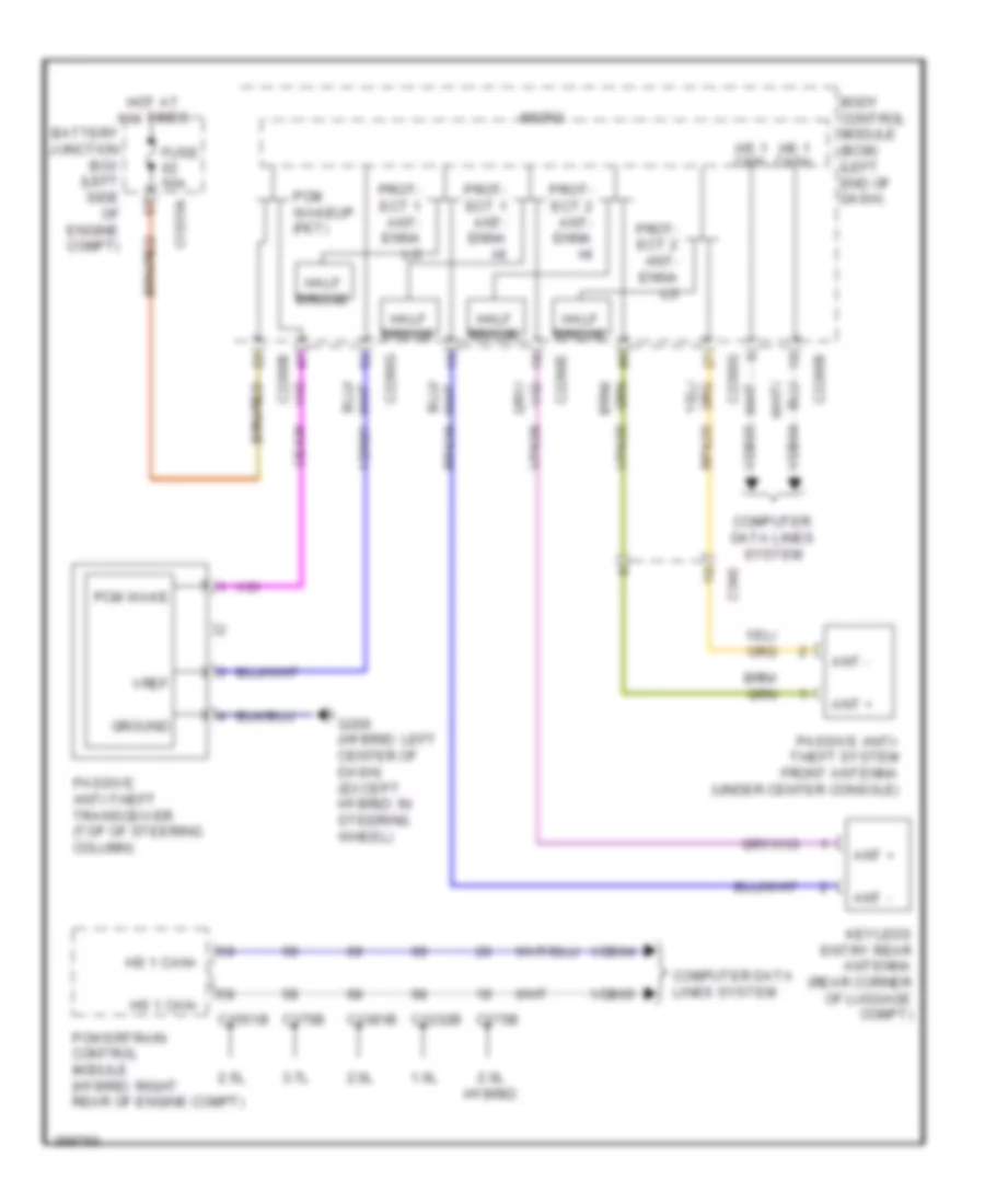
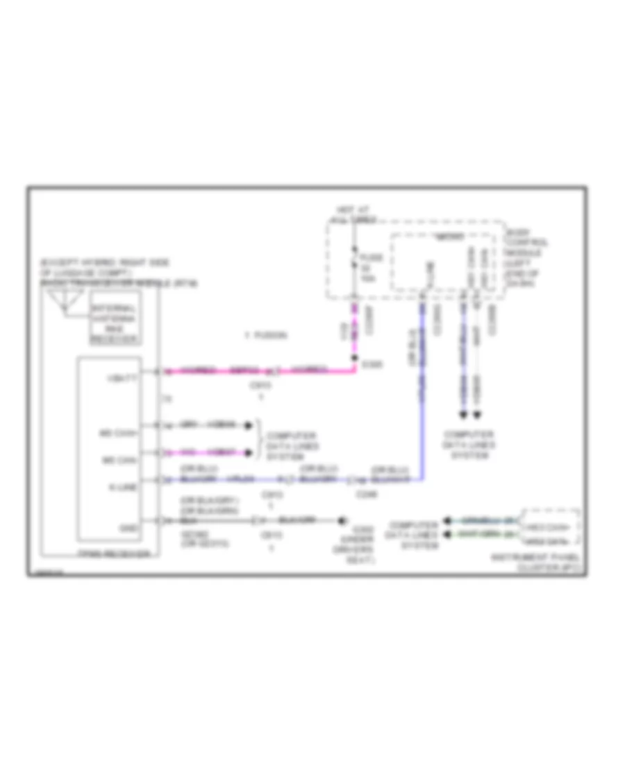
Passive Anti-theft Wiring Diagram for Ford Fusion SE 2013
List of elements for Passive Anti-theft Wiring Diagram for Ford Fusion SE 2013:
- 1.6l
- 2.0l
- 2.0l hybrid
- 2.5l
- 3.7l
- Ant +
- Ant -
- Battery junction box (left side of engine compt)
- Body control module (bcm) (left end of dash)
- C1035a
- C1232b
- C1381b
- C1551b
- C175b
- C2280b
- C2280e
- C2280g
- C340
- Ce436
- Computer data lines system
- Fuse 50a
- G200 (hybrid: left center of dash) (except hybrid: in steering wheel)
- Ground
- Half bridge
- Hot at all times
- Hs 1 can+
- Hs 1 can-
- Keyless entry rear antenna (rear corner of luggage compt)
- Micro
- Passive anti- theft system front antenna (under center console)
- Passive anti-theft transceiver (top of steering column)
- Pcm wake
- Pcm wakeup (fet)
- Powertrain control module (hybrid: right rear of engine compt)
- Prot- ect 1 ant- enna hi
- Prot- ect 1 ant- enna lo
- Prot- ect 2 ant- enna hi
- Prot- ect 2 ant- enna lo
- Rpk05
- Rpk06
- Vdb04
- Vdb05
- Vdn01
- Vpk05
- Vpk06
- Vref
BODY CONTROL MODULES
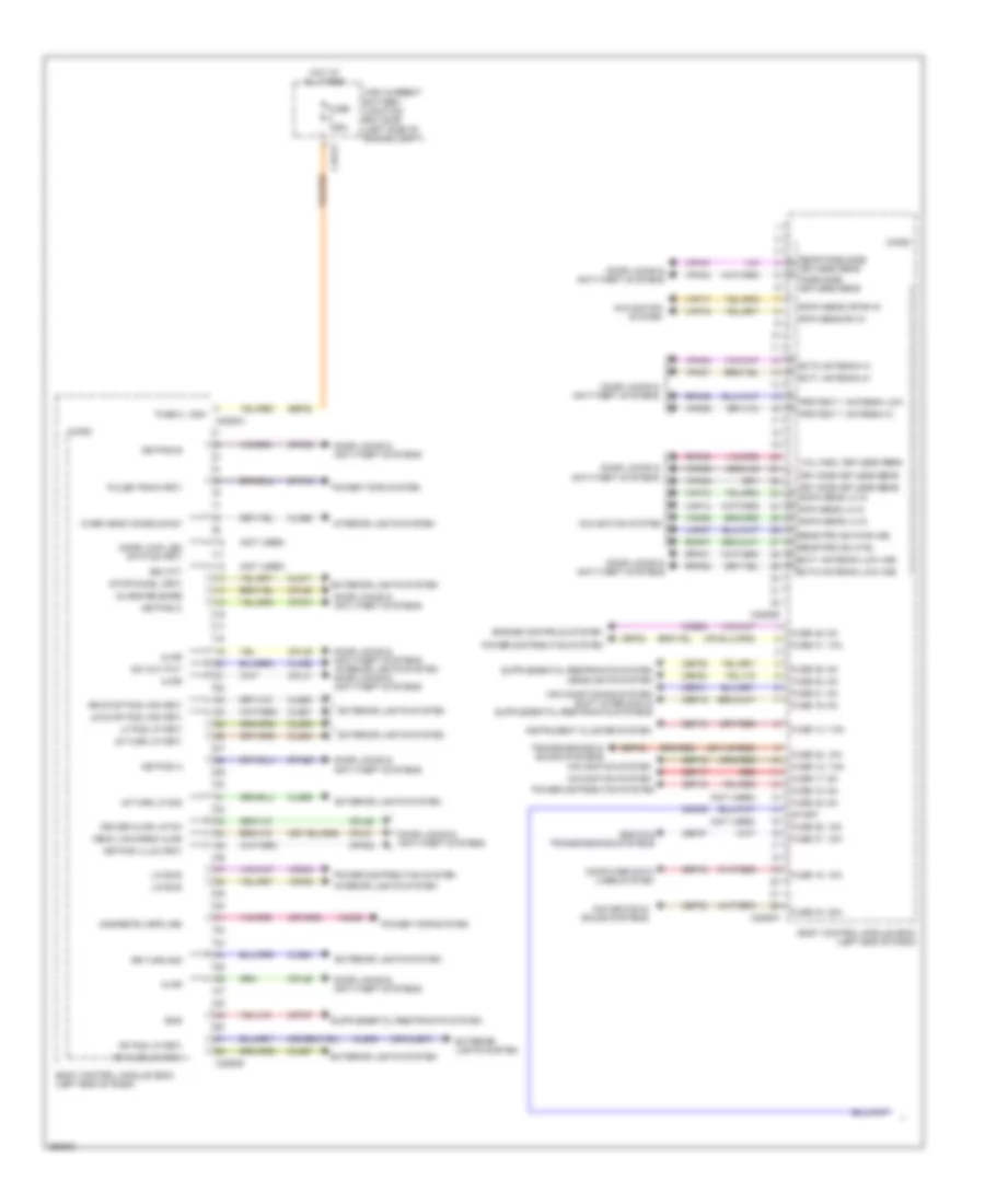
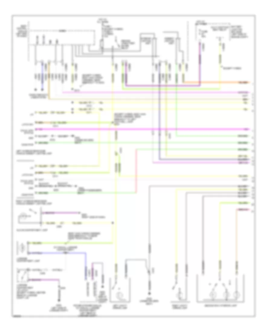
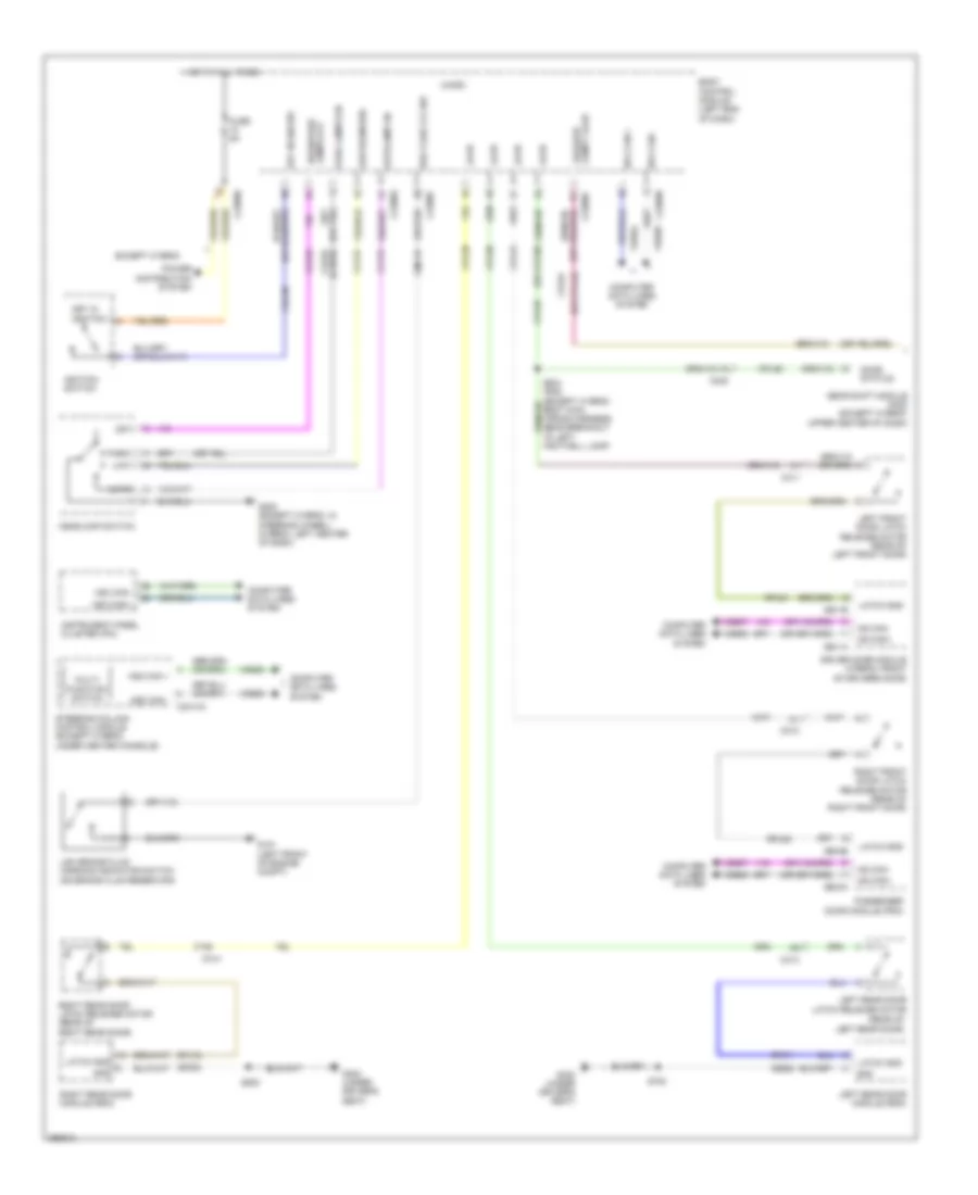
Body Control Modules Wiring Diagram, Except Hybrid (1 of 3) for Ford Fusion SE 2013
List of elements for Body Control Modules Wiring Diagram, Except Hybrid (1 of 3) for Ford Fusion SE 2013:
- (not used)
- (or cls07)
- Ajar
- Body control module (bcm) (left end of dash)
- Bsi (fit)
- C1617f
- C2280a
- C2280d
- C2280e
- C2280h
- Cbp19
- Cbp20
- Cbp21
- Cbp23
- Cbp33
- Cbp35
- Cbp37
- Ccb08
- Cdc35
- Cln68
- Cln69
- Cls05
- Cls06
- Cls17
- Cls23
- Cls27
- Cls51
- Cls53
- Cls54
- Cls55
- Computer data lines system
- Cpk28
- Cpk29
- Cpk30
- Cpk31
- Cpl26
- Cpl31
- Cpl36
- Cpl39
- Cpl60
- Cpl81
- Cpw01
- Cr167
- Deck lid/cargo ajar
- Discrete vspd (hb)
- Door lock led status (fet)
- Door locks & anti-theft systems
- Door locks & anti-theft systems interior lights system door locks & anti-theft systems
- Driver ajar latch
- Drv side keyless sens
- Engine controls system
- Ens
- Ext1 antenna hi
- Ext1 antenna low (hb)
- Ext2 antenna hi
- Ext2 antenna low (hb)
- Exterior lights system
- Fuse 12, 7.5a
- Fuse 125a
- Fuse 13, 7.5a
- Fuse 15, 10a
- Fuse 17, 5a
- Fuse 18, 5a
- Fuse 19, 5a
- Fuse 2, 125a
- Fuse 20, 5a
- Fuse 21, 5a
- Fuse 31, 10a
- Fuse 32, 10a
- Fuse 33, 20a
- Fuse 35, 5a
- Fuse 36, 15a
- Fuse 37, 15a
- Fuse 45, 5a
- Glass release
- Headlights system
- High current battery junction box (bjb) (left side of engine compt)
- Hot at all times
- Instrument cluster system
- Interior lights system
- Keypad a
- Keypad b
- Keypad c
- Keypad illum (fet)
- Lf pos lp (fet)
- Lin bus
- Lmp07
- Lr stop pos lps (fet)
- Lr turn lp (fet)
- Lr turn lp sig
- Micro
- Navigation & sound systems
- Navigation system
- Over head console sw
- Pass side keyless sens
- Power distribution system
- Power tops system
- Protect 1 antenna hi
- Protect 1 antenna low
- Pulse train (fet)
- Rapa sens lh in
- Rear pass side keyless sens
- Rear prk sn ctrl
- Rear prk sn pwr (hb)
- Red
- Rf pos lp (fet)
- Ripa sens lh in
- Ripa sens rh in
- Rmp07
- Ropa sens lh in
- Ropa sens or rh in
- Rpk01
- Rpk02
- Rpk06
- Rpk39
- Rr stop pos lps (fet)
- Rr turn lp (fet)
- Rr turn sig
- Sbf02
- Sbp12
- Sbp13
- Sbp15
- Sbp17
- Sbp18
- Sbp32
- Seats & transmissions systems
- Start
- Stop/chmsl (fet)
- Sw out put
- Transmissions & sound systems
- Vdn04
- Vdn05
- Vicl hndl keyless sens
- Vmc05
- Vmp14
- Vmp15
- Vmp16
- Vmp17
- Vmp29
- Vpk01
- Vpk02
- Vpk06
- Vpk39
- Vpk40
- Vpk46
- Vpk47
Body Control Modules Wiring Diagram, Except Hybrid (2 of 3) for Ford Fusion SE 2013
List of elements for Body Control Modules Wiring Diagram, Except Hybrid (2 of 3) for Ford Fusion SE 2013:
- (not used)
- (or sbf03)
- Ambient ltg (fet)
- Battery junction box (bjb) (left side of engine compt)
- Body control module (bcm) (left end of dash)
- C1035a
- C2280b
- C2280c
- C2280f
- Cbp22
- Cbp23
- Cbp32
- Cbp36
- Cbp38
- Cbx07
- Cdc40
- Cdc55
- Cdc56
- Cdc71
- Cdc72
- Ce226
- Ce436
- Central lock relay
- Central unlock relay
- Child lock relay
- Clf02
- Clf03
- Clf04
- Clf05
- Clf29
- Clf34
- Clf61
- Clf62
- Cln09
- Cls05
- Cls06
- Cls07
- Cls21
- Cls25
- Cls28
- Cls56
- Cls58
- Cmc19
- Computer data lines system
- Cpl10
- Cpl11
- Cpl13
- Cpl25
- Cpl51
- Cr115
- Crh02
- Cruise control system
- Deck lid/left gate
- Demand lp/batt save relay
- Door locks & anti-theft systems
- Door locks system
- Driver/fuel flap unlock relay
- Engine controls system
- Exterior lights system
- Fapa sens lh in
- Fapa sens rh in
- Fipa sens rh in
- Fuel pump (fet)
- Fuel pump on (fet)
- Fuse 10, 5a
- Fuse 2, 7.5a
- Fuse 22, 5a
- Fuse 25, 30a
- Fuse 26, 30a
- Fuse 27, 30a
- Fuse 28, 20a
- Fuse 29, 30a
- Fuse 30, 30a
- Fuse 31, 10a
- Fuse 32, 10a
- Fuse 33, 20a
- Fuse 36, 15a
- Fuse 38 30a
- Fuse 45, 5a
- Fuse 5, 20a
- Fuse 50a
- Fuse 62
- Fuse 67
- G301 (under driver's seat)
- G302 (under driver's seat)
- Gd326
- Gd382
- Gnd
- Headlights system
- Hood ajar
- Horn relay (fet)
- Horns system
- Hot at all times
- Hs1 can+
- Hs1 can-
- Instrument cluster system
- Int ltg (fet)
- Interior lights system
- Ldc59
- Lf drl lp (fet)
- Lf fog lp (fet)
- Lf high beam (fet)
- Lf inn park aid sens
- Lf low beam (fet)
- Lf out park aid sens
- Lf pos lp (fet)
- Lf turn lp (fet)
- Lmp06
- Low lvl brke flud sw
- Micro
- Mirrors system
- Mon
- Navigation system
- Park lp (fet)
- Park lps (fet)
- Park sn pwr frt (hb)
- Pcm wake up (fet)
- Power distribution system
- Protect 2 antenna low
- Pwr point rly (fet)
- Pwr point rly set (fet)
- Rapa sens lh in
- Rdc59
- Red
- Rev lps (fet)
- Rf drl (fet)
- Rf fog lamp (fet)
- Rf high beam (fet)
- Rf low beam (fet)
- Rf pos lp (fet)
- Rf turn lp (fet)
- Rmp06
- Run/acc (fet)
- Run/start (fet)
- Sb101
- Sbb62
- Sbb67
- Sbp02
- Sbp05
- Sbp10
- Sbp25
- Sbp26
- Sbp27
- Sbp28
- Sbp29
- Sbp30
- Sdc57
- Seats system
- Sen +
- Sen -
- Sens gnd
- Sound systems
- Starting/charging system
- Trunk, tailgate, fuel doors system
- Vdb04
- Vdb05
- Vln33
- Vmp10
- Vmp11
- Vmp12
- Vmp13
- Vmp20
- Vmp21
- Vpk05
- Wiper/washer system
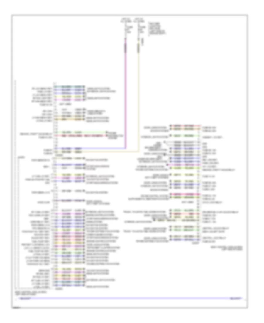
Body Control Modules Wiring Diagram, Except Hybrid (3 of 3) for Ford Fusion SE 2013
List of elements for Body Control Modules Wiring Diagram, Except Hybrid (3 of 3) for Ford Fusion SE 2013:
- (or cls34)
- (or cpr63)
- Acc
- Acc/run
- Air conditioning & headlights systems
- Anti-theft system
- Auto lamp sensor
- Auto lamp sensor gnd
- Auto park ind (fet)
- Autolamp on
- Back light (fet)
- Body control module (bcm) (left end of dash)
- Bsi (fet)
- Btsi
- C2280g
- Cdc26
- Cdc30
- Cdc33
- Cdc34
- Ce436
- Ce903
- Cet53
- Clf19
- Clf21
- Clf23
- Clf24
- Cln34
- Cln55
- Cln56
- Cls32
- Clutch pos sw pedal
- Cmp02
- Cmp18
- Cmp31
- Cmp32
- Cpk34
- Cpk35
- Cpk36
- Cpl45
- Dim +
- Dim-
- Door locks & anti-theft systems
- Eng sw
- Engine controls & transmissions systems
- Engine controls system
- Exterior lights system
- Fog lamp on
- Fusion
- Hazard sw
- Head/park lamps off
- Headlights system
- Horn sw
- Horn sw ctrl mod
- Horns system
- Hot at all times
- Ignition switch
- Interior lights system
- Key in
- Key inhibit (fet)
- Low beam req
- Micro
- Mkz
- Navigation system
- Off
- Park aid ind (fet)
- Park lamps on
- Parking actor sw
- Parking aid sw
- Pcm wakeup (fet)
- Power distribution system
- Power luggage sw
- Prct 2 antenna low (hb)
- Protect 1 antenna lo (fet)
- Prt 2 antenna hi (hb)
- Rlf14
- Rpk05
- Rrh02
- Run
- Shift interlock & transmissions systems
- Shift interlock system
- Start
- Start button (fet)
- Start/stop
- Starting/charging & shift interlock systems
- Strt/run
- Triple valve module
- Trunk, tailgate, fuel doors system
- Vdn01
- Vdn07
- Vlf14
- Vln04
- Vpk05
- Vpl56
- White light (fet)
Body Control Modules Wiring Diagram, Hybrid (1 of 3) for Ford Fusion SE 2013
List of elements for Body Control Modules Wiring Diagram, Hybrid (1 of 3) for Ford Fusion SE 2013:
- (fusion)
- (not used)
- (or cls07)
- (or cpl44)
- Ajar
- Body control module (bcm) (left end of dash)
- Bsi (fit)
- C2280d
- C2280e
- C2280h
- Cbp19
- Cbp20
- Cbp21
- Cbp23
- Cbp33
- Cbp35
- Cbp37
- Ccb08
- Cdc35
- Cln68
- Cln69
- Cls05
- Cls06
- Cls17
- Cls23
- Cls27
- Cls51
- Cls53
- Cls54
- Cls55
- Computer data lines system
- Cpk28
- Cpk29
- Cpk31
- Cpl26
- Cpl31
- Cpl36
- Cpl39
- Cpl60
- Cpl81
- Cpw01
- Cr167
- Ctrl mod 1
- Ctrl mod 3
- Ctrl mod 4
- Discrete vspd (hb)
- Door lock
- Door lock led status (fet)
- Door locks & anti-theft systems
- Door locks system
- Dr door latch
- Engine controls system
- Ens
- Ext1 antenna high (hb)
- Ext1 antenna low (hb)
- Ext2 antenna high (hb)
- Ext2 antenna low (hb)
- Exterior lights system
- Fuse 12, 7.5a
- Fuse 13, 7.5a
- Fuse 15, 10a
- Fuse 18, 5a
- Fuse 19, 5a
- Fuse 20, 5a
- Fuse 21, 5a
- Fuse 31, 10a
- Fuse 32, 10a
- Fuse 33, 20a
- Fuse 35, 5a
- Fuse 36, 15a
- Fuse 37, 15a
- Fuse 45, 5a
- Handle keyless sens
- Headlights system
- Interior lights system
- Interior lights system door locks & anti-theft systems
- Keyless vehicle sens
- Keypad a
- Keypad b
- Keypad c
- Keypad illum (fet)
- Lefr gate glass realese
- Lf pos lp (fet)
- Lmp07
- Lr stop pos lps (fet)
- Lr turn lmp
- Lr turn lp (fet)
- Micro
- Navigation & sound systems
- Navigation system
- Navigation, transmissions & sound systems
- Over head console
- Over head console sw
- Park aid sn pwr (hb)
- Parkaid sn pwr rear (hb)
- Parking aid sens
- Pass ajar sw
- Pass side keyless sens
- Power distribution system
- Power tops system
- Protect 1 antenna low
- Pulse train (fet)
- Rear pass side keyless sens
- Rf pos lp (fet)
- Rh inner parking aid sens
- Rh outer parking aid sens
- Rmp07
- Rpk01
- Rpk02
- Rpk06
- Rpk39
- Rr stop pos lps (fet)
- Rr turn lp (fet)
- Rr turn sig
- Sbp12
- Sbp13
- Sbp15
- Sbp18
- Sbp32
- Seats & transmissions systems
- Start
- Starting/charging system
- Stop chsml (fet)
- Vdn03
- Vdn04
- Vdn05
- Vmc05
- Vmp14
- Vmp15
- Vmp16
- Vmp17
- Vmp29
- Vmp30
- Vpk01
- Vpk02
- Vpk06
- Vpk30
- Vpk39
- Vpk40
- Vpk46
- Vpk47
Body Control Modules Wiring Diagram, Hybrid (2 of 3) for Ford Fusion SE 2013
List of elements for Body Control Modules Wiring Diagram, Hybrid (2 of 3) for Ford Fusion SE 2013:
- (fusion)
- (mkz)
- (not used)
- (or sbf03)
- (or sbp32)
- Ambient ltg (fet)
- Batt curr sns 5v fd (hb)
- Battery junction box (bjb) (left side of engine compt)
- Body control module (bcm) (left end of dash)
- Brke flud sw
- C1035a
- C1617f
- C2280b
- C2280c
- C2280f
- Cbp22
- Cbp23
- Cbp32
- Cbp36
- Cbp38
- Cbx07
- Cdc40
- Cdc55
- Cdc71
- Cdc72
- Ce226
- Ce436
- Central lock relay
- Central unlock relay
- Child lock relay
- Clf02
- Clf03
- Clf04
- Clf05
- Clf29
- Clf34
- Clf61
- Clf62
- Cln09
- Cls05
- Cls06
- Cls07
- Cls21
- Cls25
- Cls28
- Cls56
- Cls58
- Cmc19
- Computer data lines system
- Cpl10
- Cpl11
- Cpl13
- Cpl25
- Cpl51
- Crh02
- Deck lid/left gate relay
- Demand lp/batt save relay
- Door locks & anti-theft systems
- Door locks system
- Driver/fuel flap unlock relay
- Engine controls system
- Exterior lights system
- Fipa sens rh in
- Fuel pump (fp) relay
- Fuel pump on (fet)
- Fuse 1, 10a
- Fuse 10, 5a
- Fuse 125a
- Fuse 14, 10a
- Fuse 2, 125a
- Fuse 2, 7.5a
- Fuse 22, 5a
- Fuse 25, 30a
- Fuse 26, 30a
- Fuse 27, 30a
- Fuse 28, 20a
- Fuse 29, 30a
- Fuse 30, 30a
- Fuse 31, 10a
- Fuse 32, 10a
- Fuse 33 20a
- Fuse 36, 15a
- Fuse 45, 5a
- Fuse 5, 20a
- Fuse 50a
- Fuse 62
- Fuse 67
- G301 (under driver's seat)
- Gd326
- Gd382
- Gnd
- Headlights system
- High current battery junction box (bjb)
- Hood ajar
- Horn relay (fet)
- Horns system
- Hot at all times
- Hs1 can+
- Hs1 can-
- Instrument cluster system
- Int ltg (fet)
- Interior lights system
- Lf drl lp (fet)
- Lf fog lp (fet)
- Lf high beam (fet)
- Lf inn park aid sens
- Lf low beam (fet)
- Lf out park aid sens
- Lf pos lp (fet)
- Lf side park aid sens
- Lf turn lp (fet)
- Lmp06
- Micro
- Mirrors system
- Navigation system
- Park lp (fet)
- Park lps (fet)
- Parkaid sn pwr frt (hb)
- Pcm wake up (fet)
- Power distribution system
- Power tops system
- Pwr point rly rset (fet)
- Pwr point rly set (fet)
- Rapa sens lh in
- Red
- Rev lps (fet)
- Rf drl lp (fet)
- Rf fog lamp (fet)
- Rf high beam (fet)
- Rf low beam (fet)
- Rf pos lp (fet)
- Rf prk aid sens
- Rf turn lp (fet)
- Rmp06
- Run/acc (fet)
- Run/start (fet)
- Sb101
- Sbb62
- Sbb67
- Sbf02
- Sbp02
- Sbp05
- Sbp10
- Sbp14
- Sbp25
- Sbp26
- Sbp27
- Sbp28
- Sbp29
- Sbp30
- Seats system
- Sens gnd
- Sound systems
- Vdb04
- Vdb05
- Vln33
- Vmp10
- Vmp11
- Vmp12
- Vmp13
- Vmp20
- Vmp21
- Wiper/washer system
Body Control Modules Wiring Diagram, Hybrid (3 of 3) for Ford Fusion SE 2013
List of elements for Body Control Modules Wiring Diagram, Hybrid (3 of 3) for Ford Fusion SE 2013:
- (fusion)
- (mkz)
- (or cpl24)
- (or cpr63)
- Acc
- Acc/run
- Air conditioning & headlights systems
- Anti-theft system
- Auto lamp sensor gnd
- Auto lamp sensor input
- Auto park ind (fet)
- Autolamp on
- Back light (fet)
- Body control module (bcm) (left end of dash)
- Bsi (fet)
- Btsi
- C2280g
- Cdc26
- Cdc30
- Cdc33
- Cdc34
- Ce436
- Cet53
- Clf19
- Clf21
- Clf23
- Clf24
- Cln34
- Cln55
- Cln56
- Cls32
- Cmp02
- Cmp18
- Cmp31
- Cmp32
- Cpk34
- Cpk35
- Cpk36
- Cpl45
- Dim +
- Dim-
- Door locks & anti-theft systems
- Eng sw
- Exterior lights system
- Fog lamp on
- Hazard sw
- Head/park lamps off
- Headlights & transmissions systems
- Headlights system
- Horn sw
- Horns system
- Hot at all times
- Ignition switch
- Interior lights system
- Key in
- Key inhibit (fet)
- Left gate release sw
- Lo beam req
- Micro
- Navigation system
- Off
- Park aid ind (fet)
- Park lamps on
- Parking actor sw
- Parking aid
- Pcm wakeup (fet)
- Power distribution system
- Protect 1 antenna lo
- Protect 2 antenna high
- Protect 2 antenna low
- Rf remote recendr
- Rlf14
- Rpk05
- Rrh02
- Run
- Shift interlock & transmissions systems
- Shift interlock system
- Start
- Start button (fet)
- Start/stop
- Starting/charging & shift interlock systems
- Strt/run
- Transmissions system
- Triple valve module
- Trunk, tailgate, fuel doors & transmissions systems
- Trunk, tailgate, fuel doors system
- Vdn01
- Vdn07
- Vlf14
- Vln04
- Vln37
- Vpk05
- Vpl56
- White light (fet)
COMPUTER DATA LINES
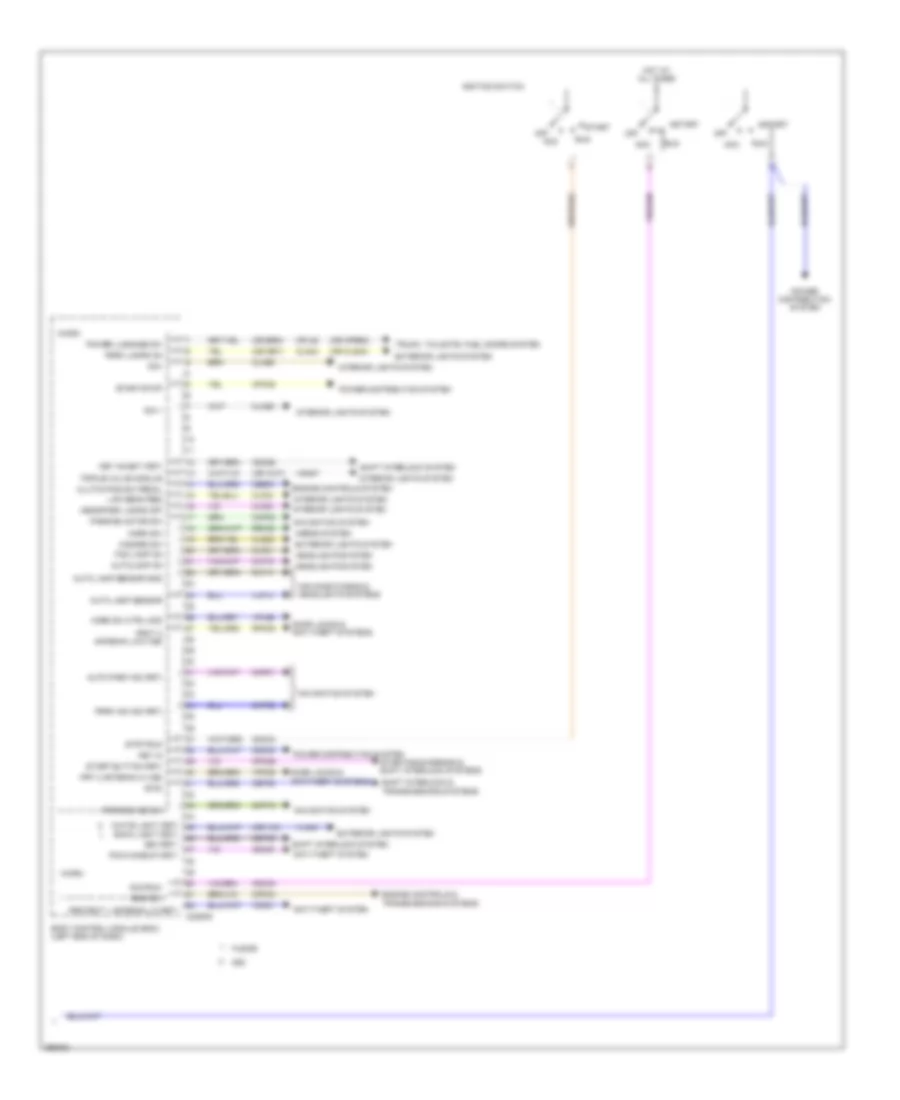
Computer Data Lines Wiring Diagram, Except Hybrid (1 of 3) for Ford Fusion SE 2013
List of elements for Computer Data Lines Wiring Diagram, Except Hybrid (1 of 3) for Ford Fusion SE 2013:
- (engine controls sensor harness, near breakout to coil on plug 3) s124
- (engine controls sensor harness, near breakout to g103) (w/ auto-start- stop system) s127
- (engine controls sensor harness, near breakout to g103) (w/ auto-start- stop system) s129
- (in steering wheel) g200
- (left end of dash) gateway module
- (lower center of dash) accessory protocol interface module (apim)
- 1.6l
- 2.0l
- 2.5l
- Body control module (bcm) (left end of dash)
- C1232b
- C1381b
- C1551b
- C215
- C2280b
- C2280h
- C238
- C3133
- C900
- Data link connector (dlc)
- Dc to dc converter control module (w/ auto start- stop system) (right rear of engine compt)
- Fuse 10a
- Fuse 7.5a
- G201 (left center of dash)
- Gd214
- Gd215
- Hot at all times
- Hs1 can +
- Hs1 can -
- Hs2 can +
- Hs2 can -
- Hs2 can - c310b
- Hs3 can +
- Hs3 can -
- Micro
- Ms can +
- Ms can -
- Occupant classification system module (under passenger's seat)
- Power train control module (pcm) (w/ auto start- stop system)
- Powertrain control module (pcm)
- Restraints control module (under center console)
- S206
- Sbp13
- Sbp15
- Splice block 17 (left side of dash)
- Splice block 37 (under passenger's seat)
- Splice block 38 (under passenger's seat)
- Vdb04
- Vdb05
- Vdb06
- Vdb07
- Vdb25
- Vdb26
- Vdb29
- Vdb30
- W/ touch screen display
- W/o touch screen display
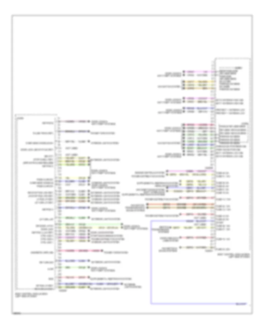
Computer Data Lines Wiring Diagram, Except Hybrid (2 of 3) for Ford Fusion SE 2013
List of elements for Computer Data Lines Wiring Diagram, Except Hybrid (2 of 3) for Ford Fusion SE 2013:
- (3.7l: battery harness, near breakout to g109)
- (ends in harness)
- (engine controls sensor harness, near breakout to anti-lock brake system module) s118
- (except 3.7l: battery harness, near breakout to c146)
- (not
- (not used)
- Anti-lock brake system (abs) module (left rear of engine compt)
- Audio digital signal processing (dsp) module (right side of luggage compt)
- Audio front control module (right rear of luggage compt)
- C146
- C1463b
- C192
- C215
- C219
- C237
- C238
- C2414a
- C260
- C900
- Evac & fill
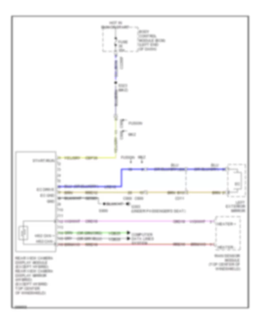
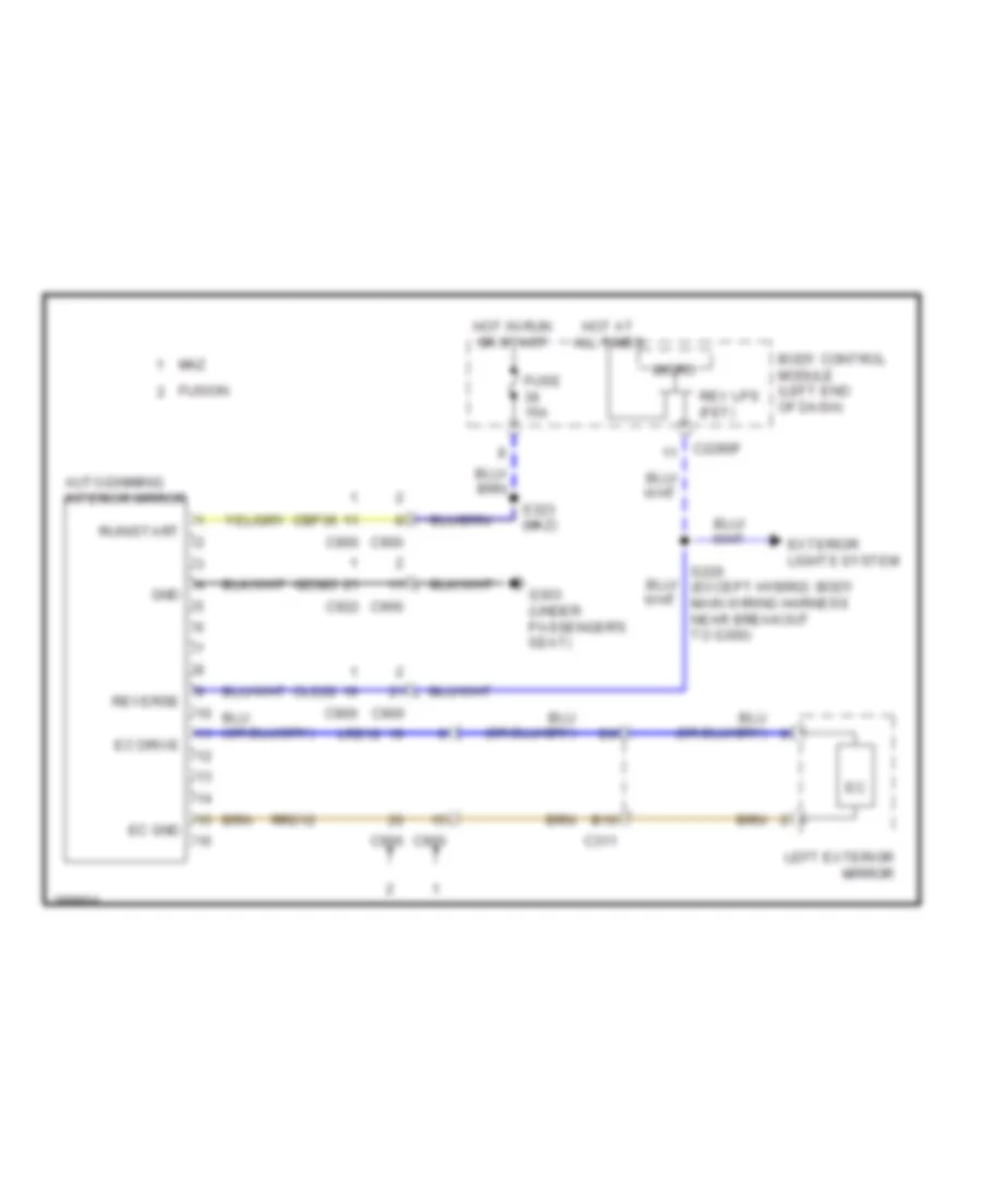
- Front control/ display interface module (fcdim) (w/ 4.2 inch display)
- Head up display (hud) module
- Hs2 can +
- Hs2 can + c4326c
- Hs2 can -
- Hs2 can - steering column control module (on steering column)
- Hs3 can +
- Hs3 can + c240a
- Hs3 can -
- Instrument panel cluster (ipc) module
- Power steering control module (right rear of engine compt)
- Proximity warning radar unit (left front of engine compt)
- Rearview camera display module (top center of windshield)
- S107 (engine controls sensor harness, near breakout to c134)
- S108 (engine controls sensor harness, near breakout to c134)
- S115
- S116
- S117 (engine controls sensor harness, near breakout to c192)
- S137 (battery harness, near breakout to c146)
- S138
- Splice block 18 (left side of dash)
- Splice block 20 (center of dash)
- Splice block 21 (center of dash)
- Splice block 39 (near base of right "b" pillar)
- Splice block 59 (top of right "a" pillar)
- Splice block 8 (w/ 4.2 inch display)
- Used)
- Vdb25
- Vdb26
- Vdb29
- Vdb30
- W/ head up display
- W/ sony audio
- W/o head up display
- W/o sony audio
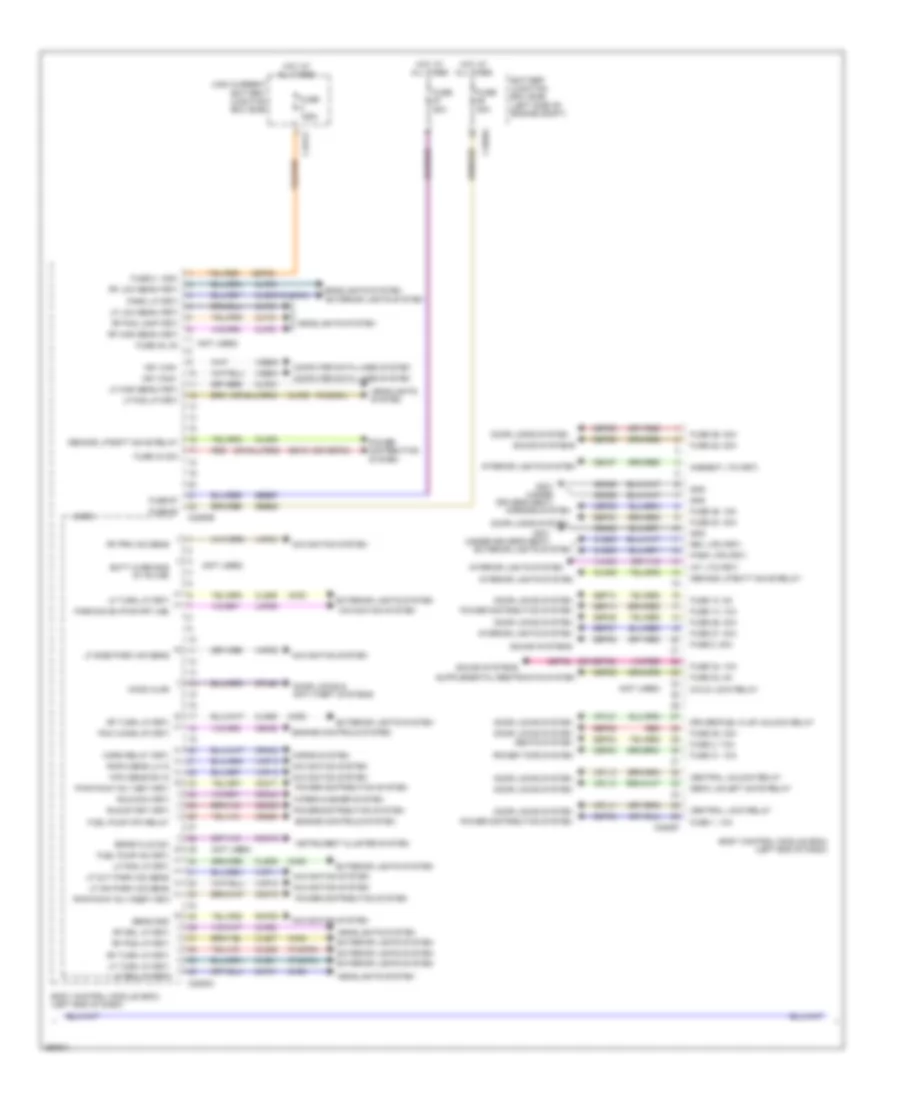
Computer Data Lines Wiring Diagram, Except Hybrid (3 of 3) for Ford Fusion SE 2013
List of elements for Computer Data Lines Wiring Diagram, Except Hybrid (3 of 3) for Ford Fusion SE 2013:
- (ends in harness)
- (not used)
- C237
- C248
- C260
- C3052
- C311
- C312
- C501a
- C913
- Control module (sod-l)
- Control module (sod-r)
- Driver door module (ddm)
- Driver seat module (dsm) (under driver's seat)
- Front controls interface module (center of dash)
- Global positioning system module (right end of dash)
- Left side obstacle detection
- Ms can +
- Ms can + c2402a
- Ms can + c652a
- Ms can -
- Ms can - c341d
- Passenger door module (pdm)
- Radio transceiver module (right side of luggage compt)
- Right side obstacle detection
- Splice block 15 (lower left side of dash)
- Splice block 16 (left side of dash)
- Splice block 32 (w/ blind spot information system) (left side of luggage compt)
- Splice block 33 (under driver's seat)
- Splice block 34 (base of left kick panel)
- Splice block 35 (left kick panel)
- Splice block 36 (right kick panel)
- Splice block 41 (w/ blind spot information system) (right side of luggage compt)
- Used) (not
- Vdb06
- Vdb07
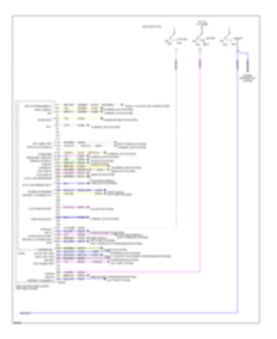
Computer Data Lines Wiring Diagram, Hybrid (1 of 3) for Ford Fusion SE 2013
List of elements for Computer Data Lines Wiring Diagram, Hybrid (1 of 3) for Ford Fusion SE 2013:
- (engine controls sensor harness, in breakout to c215) s129
- (engine controls sensor harness, near breakout to battery junction box)
- (front of center console) accessory protocol interface module (apim)
- (left center of dash) g200
- (left end of dash) gateway module
- (power steering hev harness, near breakout to high current battery junction box)
- (power steering hev harness, near breakout to high current battery junction box) s199
- Air conditioning control module (accm)
- Battery energy control module (becm) (behind left side of rear seat)
- Body control module (bcm) (left end of dash)
- C1458a
- C146
- C175b
- C215
- C2280b
- C2280h
- C238
- C3133
- C900
- Charge port light ring (at charge port)
- Data link connector (dlc)
- Fuse 10a
- Fuse 7.5a
- G201 (left center of dash)
- Gd214
- Gd215
- Hot at all times
- Hs1 can +
- Hs1 can + c4237a
- Hs1 can -
- Hs2 can +
- Hs2 can -
- Hs2 can - c310b
- Hs3 can +
- Hs3 can -
- Micro
- Module (ocsm) (under passenger's seat)
- Ms can +
- Ms can -
- Occupant classification
- Powertrain control module (pcm) (right rear of engine compt)
- Restraints control module (under center console)
- S124
- S127
- S198
- S206
- Sbp13
- Sbp15
- Secondary onboard diagnostic module c (sobdmc)/ transmission control module (tcm) (left side of engine compt)
- Splice block 17 (left side of dash)
- Splice block 37 (under passenger's seat)
- Splice block 38 (under passenger's seat)
- Splice block 6 (under center console)
- Vdb04
- Vdb05
- Vdb06
- Vdb07
- Vdb25
- Vdb26
- Vdb29
- Vdb30
- W/ touch screen display
- W/o touch screen display
Computer Data Lines Wiring Diagram, Hybrid (2 of 3) for Ford Fusion SE 2013
List of elements for Computer Data Lines Wiring Diagram, Hybrid (2 of 3) for Ford Fusion SE 2013:
- (engine controls sensor harness, near breakout to transmission range control module)
- (left front of vehicle)
- (not used)
- Anti-lock brake system (abs) control module (left rear of engine compt)
- Audio digital signal processing (dsp) module (under right side of package tray)
- Audio front control module (acm) (center of dash)
- C146
- C1463b
- C192
- C215
- C219
- C237
- C238
- C2414a
- C260
- C900
- Digital audio control module c
- Ends in harness
- Evac & fill
- Front control/ display interface module (w/ 4.2 inch display) (center of dash) hs3 can -
- Head up display (hud) module
- Hs2 can +
- Hs2 can + c4326c
- Hs2 can -
- Hs3 can +
- Hs3 can + c240a
- Hs3 can -
- Hs3 can - c4820a
- Instrument panel cluster (ipc)
- Power steering control module (pscm)
- Proximity warning radar unit (left front of engine compt)
- Rearview camera display mirror
- S128
- S130
- S137
- S138
- Splice block 14 (top of right "a" pillar)
- Splice block 18 (left side of dash)
- Splice block 20 (center of dash)
- Splice block 21 (center of dash)
- Splice block 22 (w/ 4.2 inch display) (left side of dash)
- Splice block 39 (w/o blind spot) (near base of right "b" pillar)
- Splice block 40 (right side of luggage compt)
- Steering column control module (sccm)
- Transmission range control module (trcm) (right rear corner of engine compt)
- Vdb25
- Vdb26
- Vdb29
- Vdb30
- W/ head up display
- W/o head up display
Computer Data Lines Wiring Diagram, Hybrid (3 of 3) for Ford Fusion SE 2013
List of elements for Computer Data Lines Wiring Diagram, Hybrid (3 of 3) for Ford Fusion SE 2013:
- (ends in harness)
- (not used)
- C237
- C248
- C260
- C3052
- C311
- C312
- C501a
- C913
- Control module (sod-l)
- Control module (sod-r)
- Driver door module (front of driver's door)
- Driver's seat module (under driver's seat)
- Front control interface module (center of dash)
- Global positioning system module (behind instrument cluster)
- Left side obstacle detection
- Ms can +
- Ms can + c2402a
- Ms can + c652a
- Ms can -
- Ms can - c341d
- Passenger door module (pdm)
- Radio transceiver module (rtm)
- Right side obstacle detection
- Splice block 15 (lower left side of dash)
- Splice block 16 (left side of dash)
- Splice block 32 (left front of luggage compt)
- Splice block 33 (under driver's seat)
- Splice block 34 (base of left kick panel)
- Splice block 35 (left kick panel)
- Splice block 36 (right kick panel)
- Splice block 39 (w/ blind spot) (near base of right "b" pillar)
- Used) (not
- Vdb06
- Vdb07
- W/ blind spot
- W/o blind spot
COOLING FAN
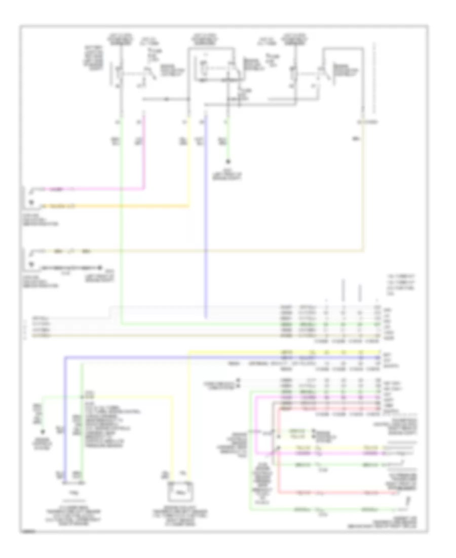
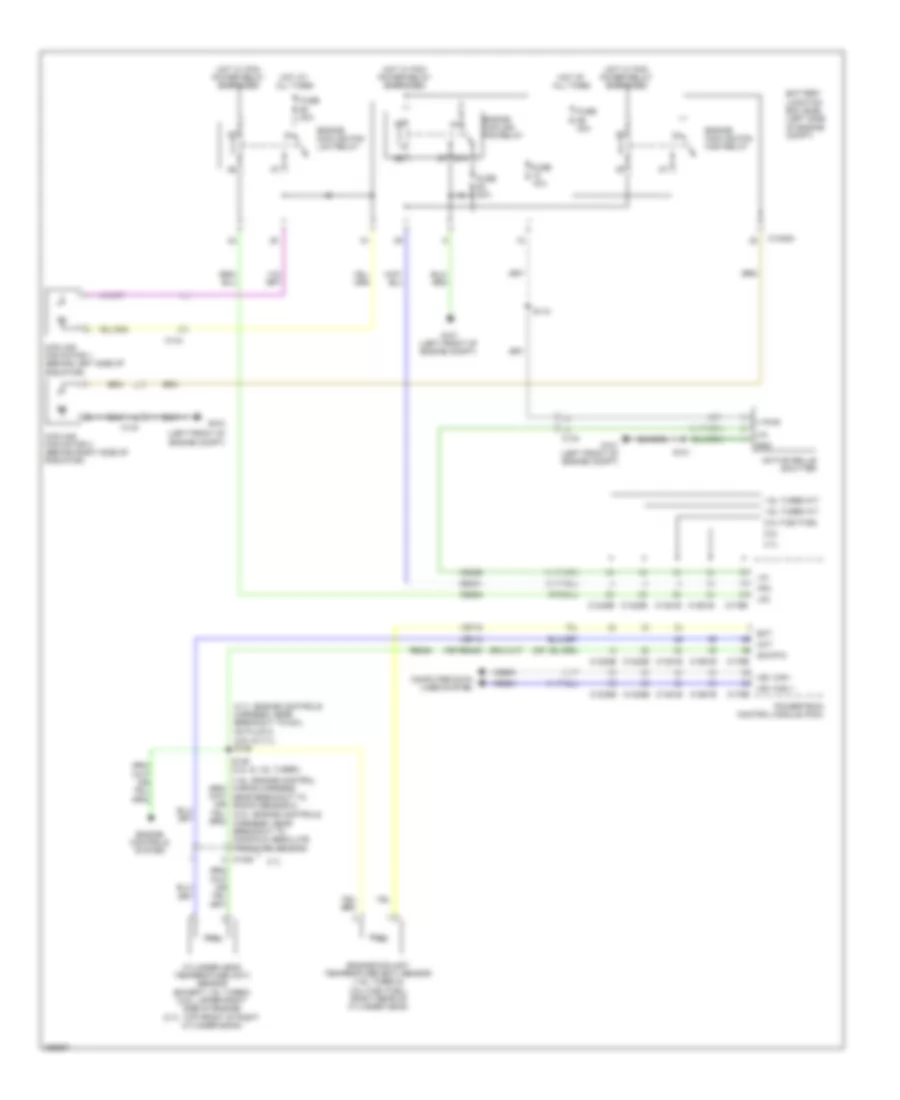
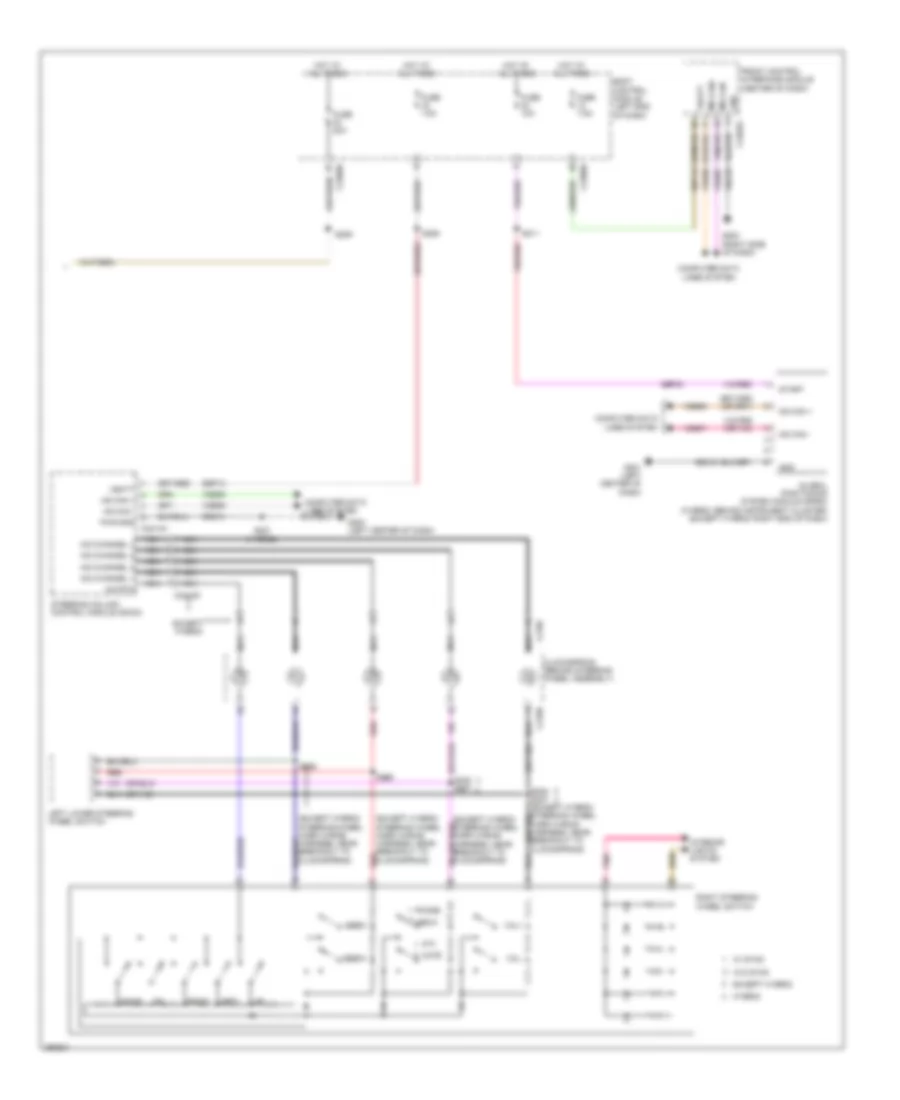
Cooling Fan Wiring Diagram, Except Hybrid for Ford Fusion SE 2013
List of elements for Cooling Fan Wiring Diagram, Except Hybrid for Ford Fusion SE 2013:
- (1.6l: engine control wiring harness, near breakout to knock sensor 2)
- (2.5l & 3.7l) s146
- (3.7l: engine controls harness, near breakout to coil on plug 3)
- (left front of engine compt)
- (or re405)
- 1.6l turbo a/t
- 1.6l turbo m/t
- 2.0l flex fuel
- 2.5l
- 3.7l
- 87a
- Active grille shutter
- Battery junction box (bjb) (left side of engine compt)
- C1035a
- C1046
- C1232b
- C1232e
- C134
- C1381b
- C1381e
- C144
- C1551b
- C1551e
- C175b
- C175e
- Ce202
- Cec01
- Cht
- Computer data lines system
- Cooling fan motor 1 (behind left side of radiator)
- Cooling fan motor 2 (behind right side of radiator)
- Cylinder head temperature (cht) sensor (except 1.6l turbo) (2.5l: upper right side of engine) (3.7l: top front of right cylinder bank)
- Ect
- Engine controls system
- Engine coolant temperature (ect) sensor (1.6l turbo & 2.0l flex fuel) (right rear of cylinder head)
- Engine cooling fan high relay
- Engine cooling fan low relay
- Engine cooling fan relay
- Fuse 15a
- Fuse 20a
- Fuse 30a
- G100
- G101 (left front of engine compt)
- Gnd
- Hfc
- Hot at all times
- Hot w/ pcm power relay energized
- Hs1 can +
- Hs1 can -
- Lfc
- Lin
- Powertrain control module (pcm)
- Re454
- S101
- S110
- S149 (2.0l & 1.6l turbo)
- Sig rtn
- V pwr
- Vdb04
- Vdb05
- Vdn06
- Ve712
- Ve716
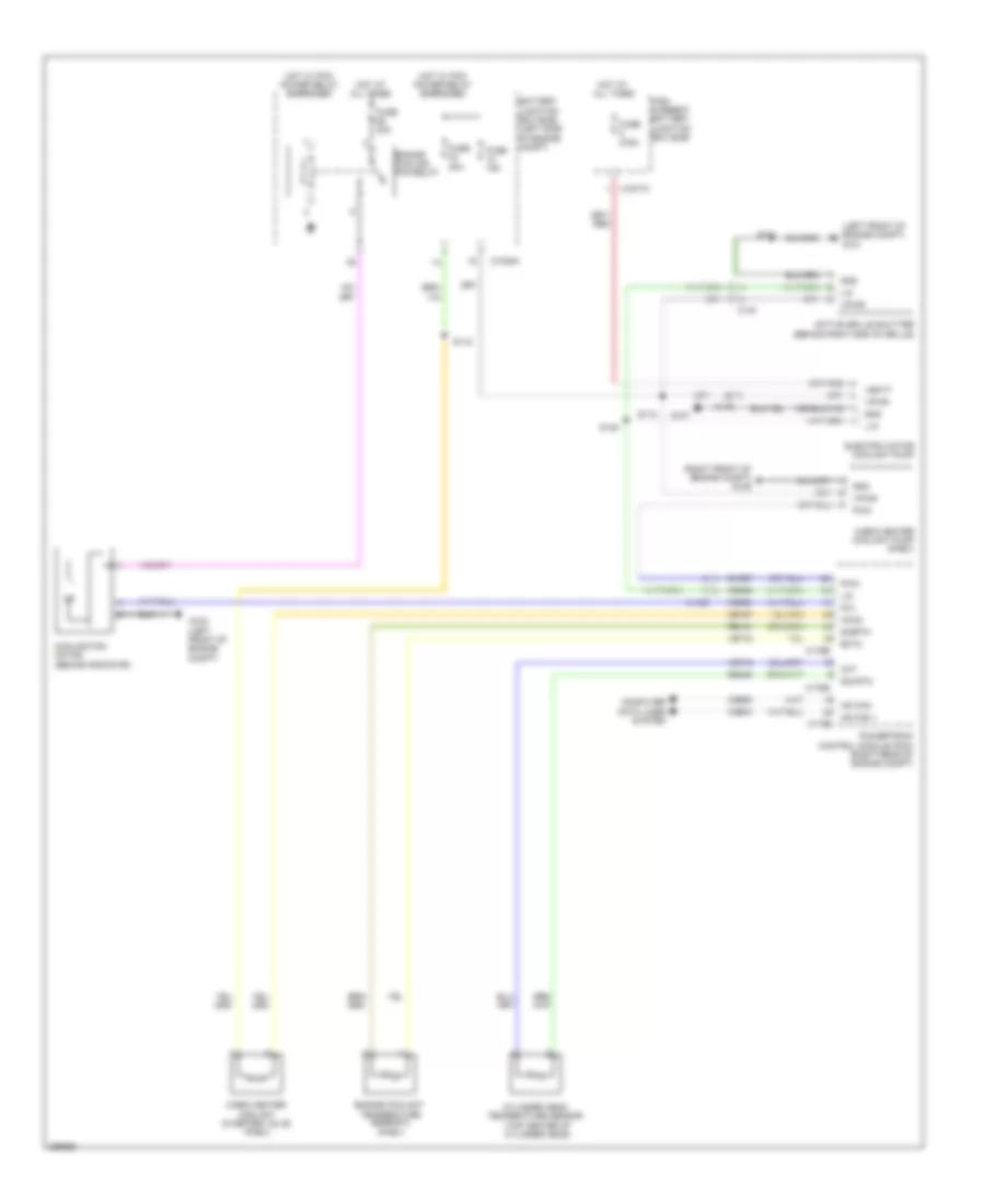
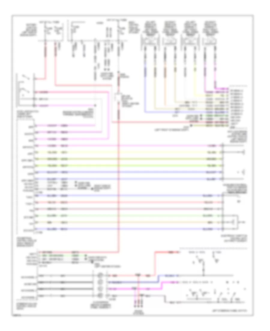
Cooling Fan Wiring Diagram, Hybrid for Ford Fusion SE 2013
List of elements for Cooling Fan Wiring Diagram, Hybrid for Ford Fusion SE 2013:
- (left front of engine compt)
- (left front of engine compt) g101
- (right front of engine compt) g106
- (top center of cylinder head)
- Active grille shutter (behind right end of grille)
- Battery junction box (bjb) (left side of engine compt)
- C1026
- C1035a
- C134
- C146
- C1617k
- C175b
- C175e
- Cabin heater coolant diverter valve (phev)
- Cabin heater coolant pump (phev)
- Ce167
- Ch307
- Cht
- Computer data lines system
- Cooling fan motor (behind radiator)
- Cylinder head temperature sensor
- Ect2
- Electric motor coolant pump
- Engine coolant temperature sensor 2 (phev)
- Engine cooling fan relay
- Fcv
- Fuse 15a
- Fuse 20a
- Fuse 275a
- Fuse 30a
- G100
- G107
- Gnd
- Hcho
- High current battery junction box (bjb)
- Hot at all times
- Hot w/ pcm power relay energized
- Hs can +
- Hs can -
- Lin
- Powertrain control module (pcm) (right rear of engine compt)
- Pwm
- Re141
- Re405
- S101
- S110
- S115
- S145
- Sig rtn
- Sigrtn
- Vbatt
- Vdb04
- Vdb05
- Vdn06
- Ve712
- Ve716
- Vec03
- Vpwr
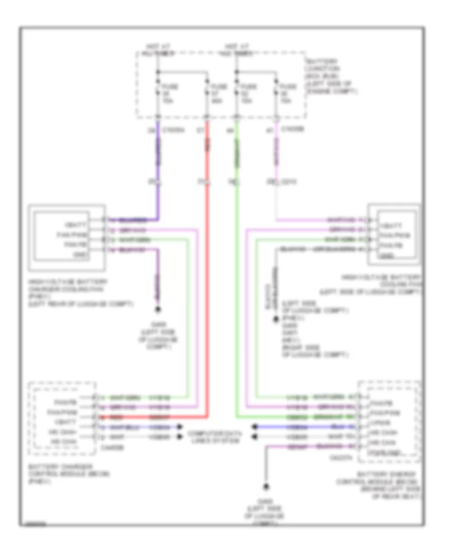
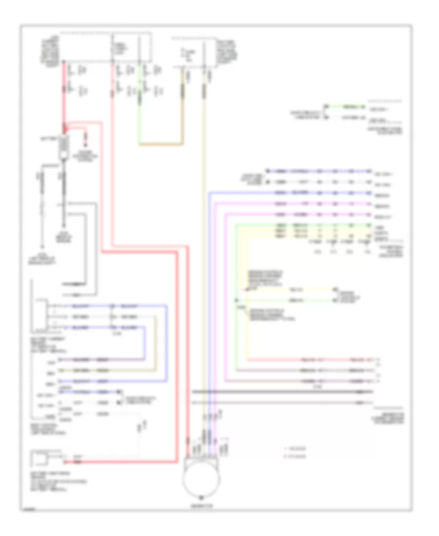
Hybrid Cooling Fan Wiring Diagram, Hybrid for Ford Fusion SE 2013
List of elements for Hybrid Cooling Fan Wiring Diagram, Hybrid for Ford Fusion SE 2013:
- (behind left side of rear seat)
- (left side of luggage compt) (phev) g400 g401 (hev) (right side of luggage compt)
- Battery charger control module (becm) (phev)
- Battery energy control module (becm)
- Battery junction box (rjb) (left side of engine compt)
- C1035a
- C1035b
- C215
- C4237a
- C4455b
- Cbb52
- Computer data lines system
- Fan fb
- Fan pwm
- Fuse 15a
- Fuse 40a
- G400 (left side of luggage compt)
- Gd347
- Gnd
- High voltage battery charger cooling fan (phev) (left rear of luggage compt)
- High voltage battery cooling fan (left side of luggage compt)
- Hot at all times
- Hs can+
- Hs can-
- Pwr gnd
- Red
- Sbb57
- Vbatt
- Vdb04
- Vdb05
- Vpwr
- Vyb18
- Vyb19
CRUISE CONTROL
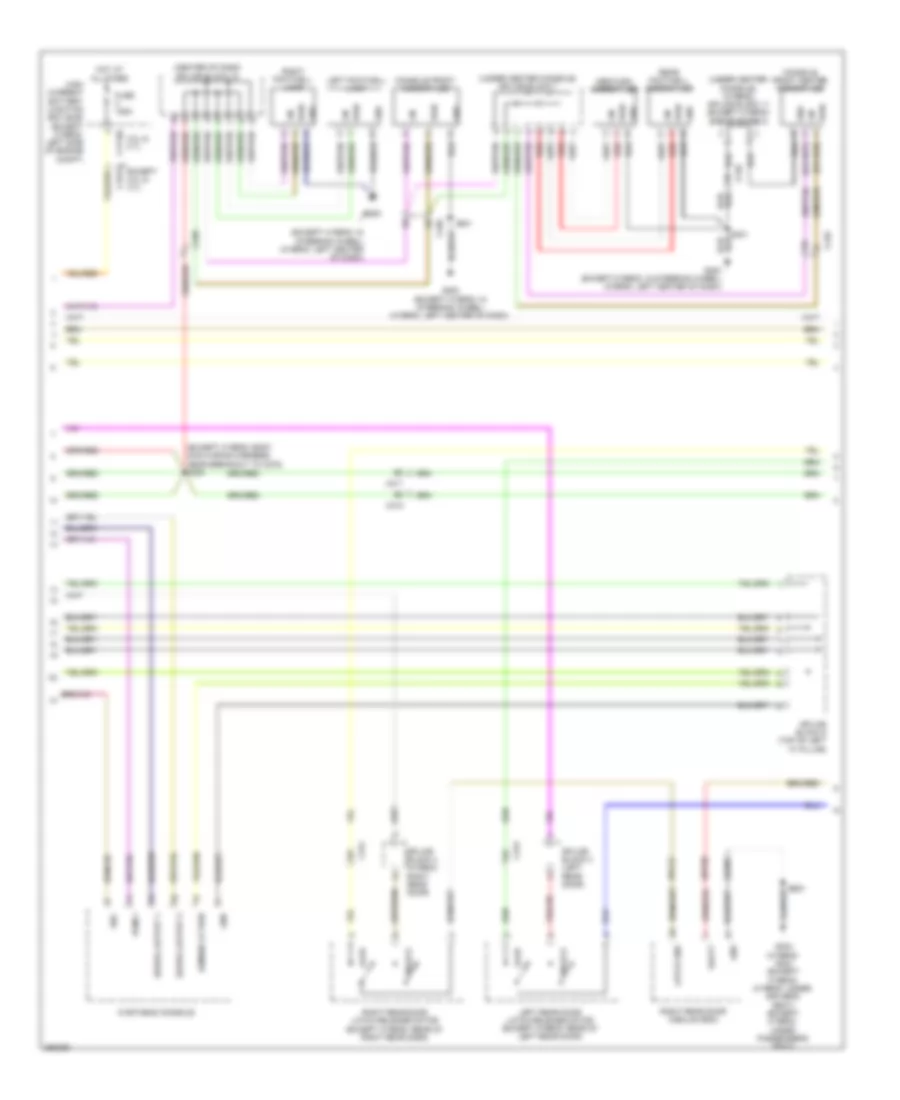
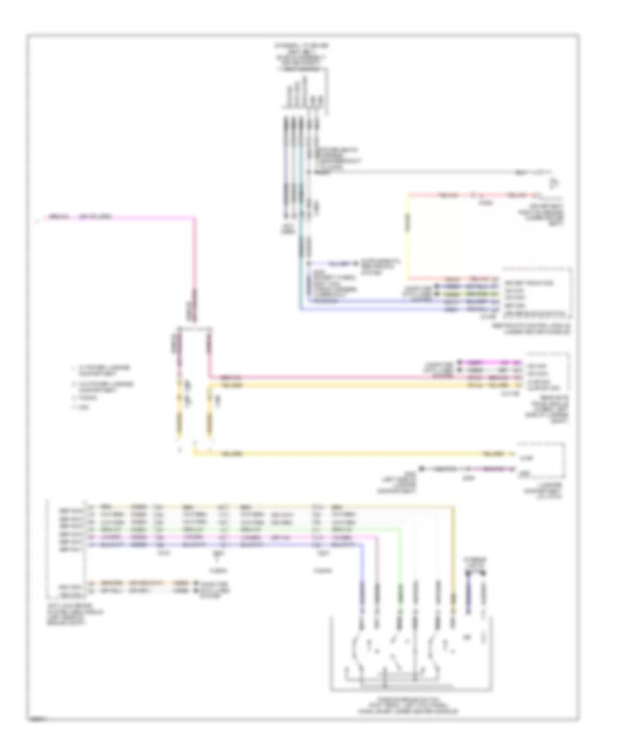
Cruise Control Wiring Diagram, Except Hybrid (1 of 2) for Ford Fusion SE 2013
List of elements for Cruise Control Wiring Diagram, Except Hybrid (1 of 2) for Ford Fusion SE 2013:
- (left front of engine compt) g101
- (not used)
- (or ret04)
- 1.6l
- 1.6l turbo
- 1.6l turbo a/t
- 2.0l
- 2.5l
- 3.7l
- A/t
- Accelerator pedal position sensor (left side of dash)
- App1
- App2
- Apprtn1
- Apprtn2
- Appvref1
- Appvref2
- Battery junction box (bjb) (left side of engine compt)
- Body control module (left end of dash)
- Bpp
- Bps
- C1035a
- C1035b
- C1232b
- C1232e
- C1381b
- C1381e
- C1551b
- C1551e
- C1551t
- C175b
- C175e
- C215
- C219
- C2280b
- C2280f
- C2280h
- Cbb23
- Ccb08
- Ce412
- Ce426
- Ces09
- Computer data lines system
- Electronic throttle control (etc) (2.0l & 2.5l:
- Etcref
- Etcrtn
- Except 1.6l turbo
- Except 3.7l
- Fuse 10a
- Fuse 15a
- Fuse 5a
- Fuse 7.5a
- G101 (left front of engine compt)
- G104 (right side of engine compt)
- Gd113
- Gd120
- Gnd
- Hot at all times
- Hot in start or run
- Hs can+
- Hs can-
- Hs1 can+
- Hs1 can-
- Hs2 can+
- Hs2 can-
- Le111
- Le134
- Le136
- Le137
- M/t
- Micro
- On throttle body)
- Oss
- Powertrain control module (pcm)
- Proximity warning radar unit (left front of engine compt)
- Pwr gnd
- Re134
- Re136
- Re137
- Ret24
- S204 (engine controls sensor harness, near breakout to coil on plug 3)
- S206 (fusion)
- S214
- S305
- Sbp32
- Stop lamp switch (under left side of dash)
- Tacm +
- Tacm -
- Tp1
- Tp2
- Trp
- Tss/oss/ tr gnd c175t
- Turbo
- Vbatt
- Vdb04
- Vdb05
- Vdb25
- Vdb26
- Ve701
- Ve702
- Ve818
- Ve819
- Vet26
- Vet32
- Vpwr
- Vref tss/oss/ tr vppwr
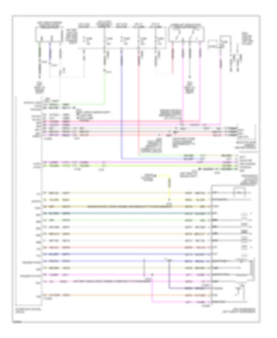
Cruise Control Wiring Diagram, Except Hybrid (2 of 2) for Ford Fusion SE 2013
List of elements for Cruise Control Wiring Diagram, Except Hybrid (2 of 2) for Ford Fusion SE 2013:
- (2.0l & 1.6l turbo) (1.6l turbo: battery cable (battery cable
- (except 2.0l: battery cable wiring harness, in breakout to transmission) (2.0l: engine controls harness, near breakout to transmission) s142
- (right center of dash) (mkz) splice block 26
- (steering wheel horn wiring harness, near breakout to clockspring)
- 0ss vp pwr
- 2.0l & 1.6l turbo
- 2.5l
- 3.7l
- 6f35 transmission (left side of transmission)
- 6f50 transmission (left side of transmission)
- Ad channel 2
- Ad channel 3
- Ad channel 4
- Ad return
- C1520a
- C218b
- C218c
- C2414a
- C2414d
- Clock spring (behind steering wheel assembly)
- Cncl
- Computer data lines system
- Except 3.7l
- Fusion
- G200 (in steering wheel)
- Gap dn
- Gap up
- Gd124
- Hs2 can+
- Hs2 can-
- Left steering wheel switch
- Logic gnd
- Mkz
- Nca
- Off
- On/off
- Oss
- Oss/tr gnd
- Oss/tr pwr
- Red
- Res
- Res/ cncl
- S143
- S143 s141 (2.5l)
- S221 (mkz)
- S237
- S238
- S239
- Sbp13
- Set +
- Set -
- Sound systems
- Steering column control module (on steering column)
- To transmission)
- Tr-p
- Transmissions system
- Trs
- Vbatt
- Vdb25
- Vdb26
- W/ adaptive cruise control
- W/o adaptive cruise control
- Wiring harness, in breakout
- Wiring harness, in breakout to transmission) (2.0l: engine controls harness, near breakout to transmission)
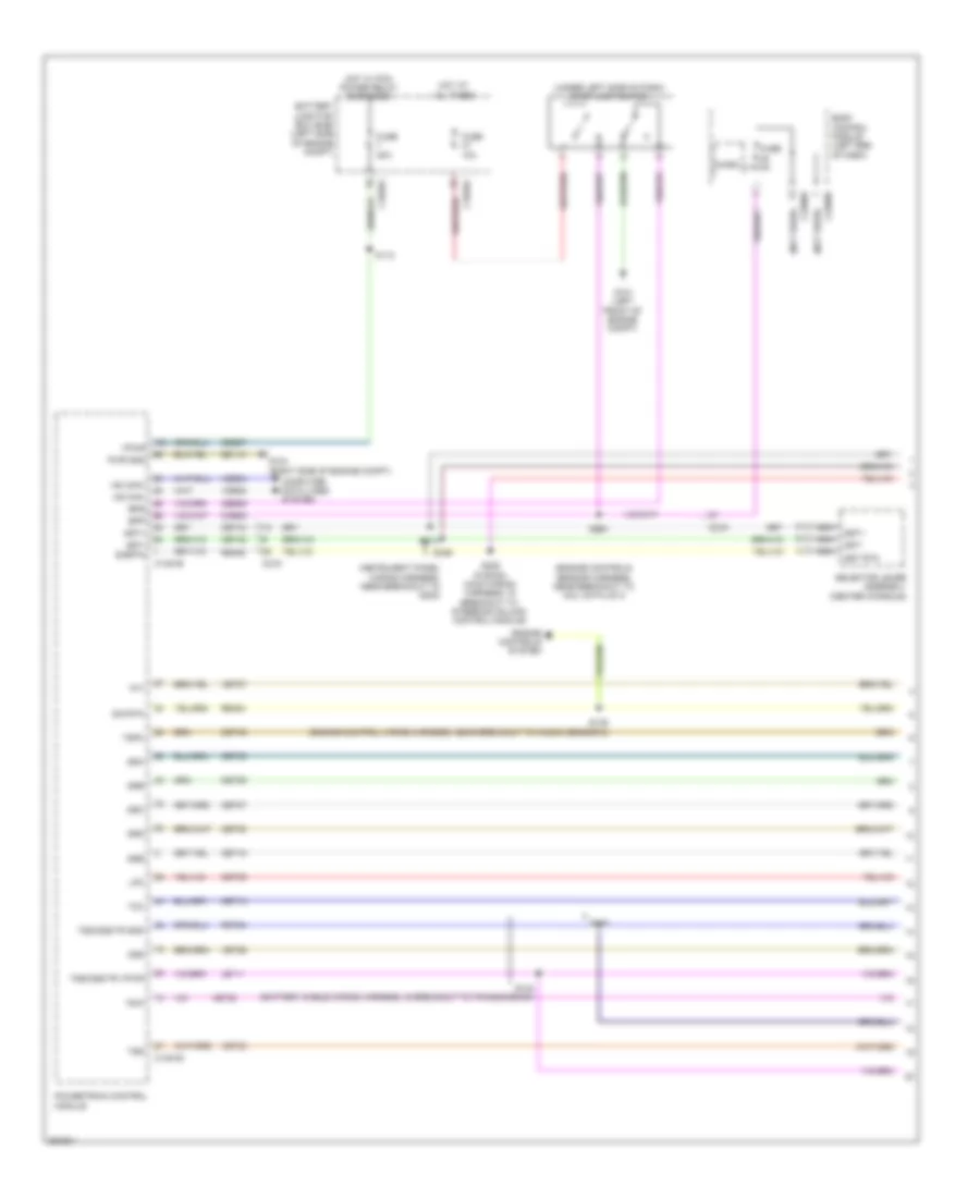
Cruise Control Wiring Diagram, Hybrid for Ford Fusion SE 2013
List of elements for Cruise Control Wiring Diagram, Hybrid for Ford Fusion SE 2013:
- (not used)
- (on left front hub assembly) left front wheel speed sensor
- (on left rear hub assembly) left rear wheel speed sensor
- (on right front hub assembly) right front wheel speed sensor
- (on right rear hub assembly) right rear wheel speed sensor
- (right side of engine compt) g105
- Accelerator pedal position sensor (on accelerator pedal bracket)
- Ad channel 2
- Ad channel 3
- Ad channel 4
- Ad return
- Anti-lock brake system (abs) control module (left rear of engine compt)
- App rtn1
- App rtn2
- App1
- App2
- Appv ref1
- Appv ref2
- Battery junction box (bjb) (left side of engine compt)
- Body control module (left end of dash)
- Bpp
- Bps
- C1010
- C1035a
- C175b
- C175e
- C2114a
- C215
- C218b
- C219
- C2280b
- C2280h
- Ccb08
- Ce412
- Ce426
- Ces09
- Clockspring (behind steering wheel assembly)
- Cncl
- Computer data lines system
- Electronic throttle control (etc) (on throttle body)
- Etc ref
- Etc rtn
- Fuse 10a
- Fuse 30a
- Fuse 5a
- Fuse 7.5a
- G102 (left front of engine compt)
- G200 (left center of dash)
- Gd113
- Gd121
- Gd124
- Gnd
- Hot at all times
- Hs can+
- Hs can-
- Hs1 can+
- Hs1 can-
- Hs2 can+
- Hs2 can-
- Le134
- Le136
- Le137
- Left steering wheel switch
- Lf sens hi
- Lf sens lo
- Lr sens hi
- Lr sens lo
- Micro
- Nca
- Off
- Powertrain control module (right rear of engine compt)
- Pwr gnd
- Rca17
- Rca18
- Rca19
- Rca20
- Re134
- Re136
- Re137
- Re406
- Red
- Res
- Rf sens hi
- Rf sens lo
- Rr sens hi
- Rr sens lo
- S204 (engine controls sensor harness, near breakout to c1010)
- S237
- S238
- S239
- Sbb69
- Sbp13
- Set +
- Set -
- Sig
- Sig rtn
- Sound systems
- Splice block 26 (mkz) (right center of dash)
- Steering column control module (sccm)
- Stop lamp switch (under left side of dash)
- Tacm +
- Tacm -
- Tp1
- Tp2
- Vbatt
- Vca03
- Vca04
- Vca05
- Vca06
- Vdb04
- Vdb05
- Vdb25
- Vdb26
- Ve701
- Ve702
- Ve818
- Ve819
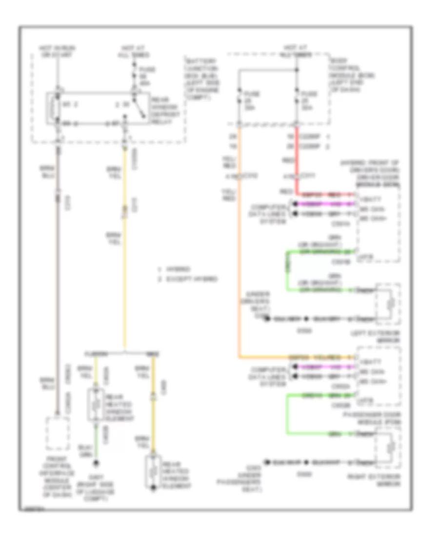
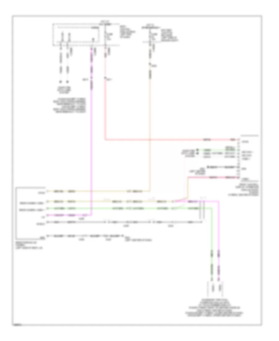
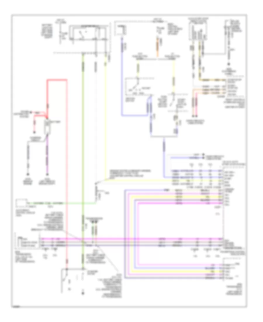
DEFOGGERS
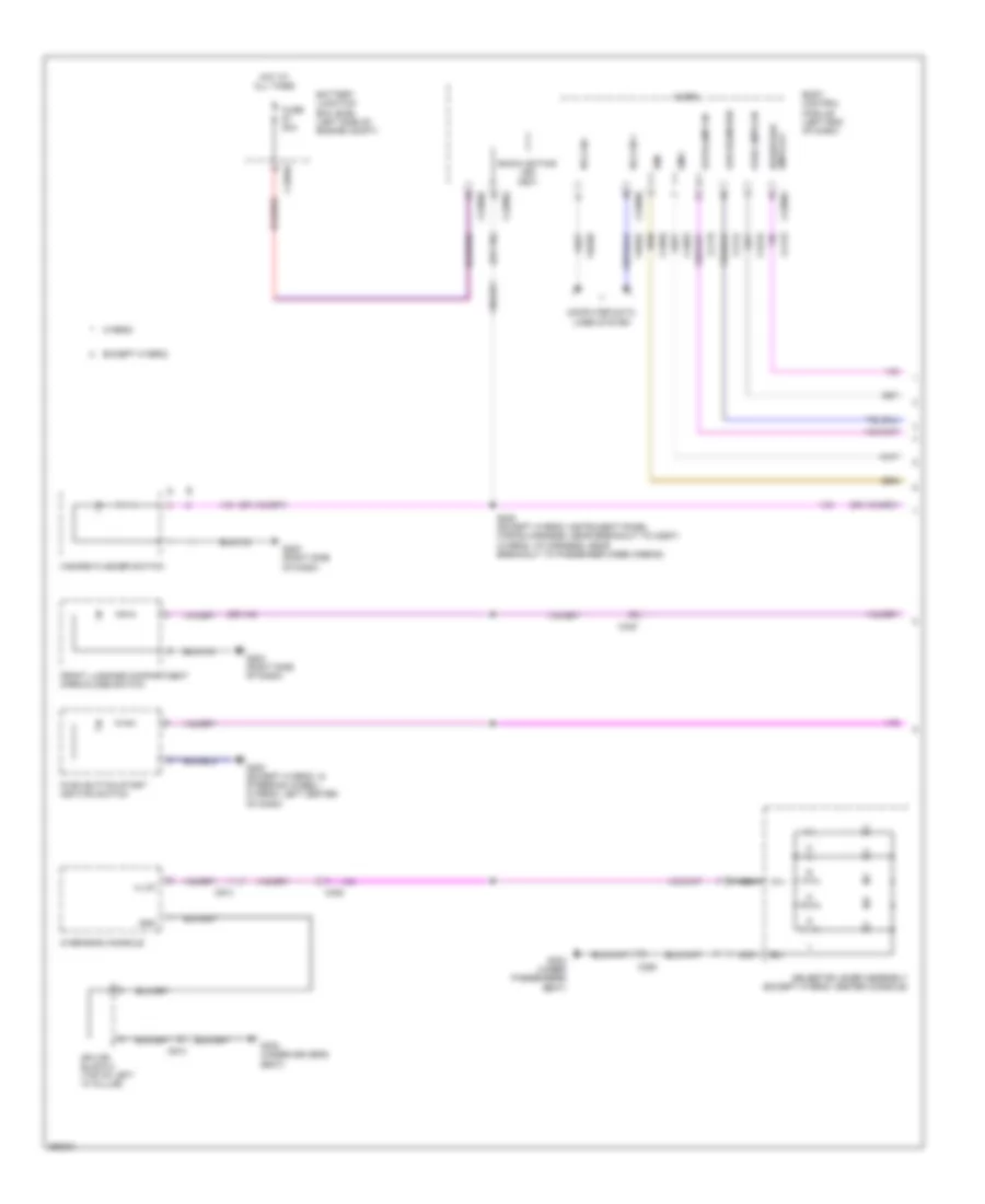
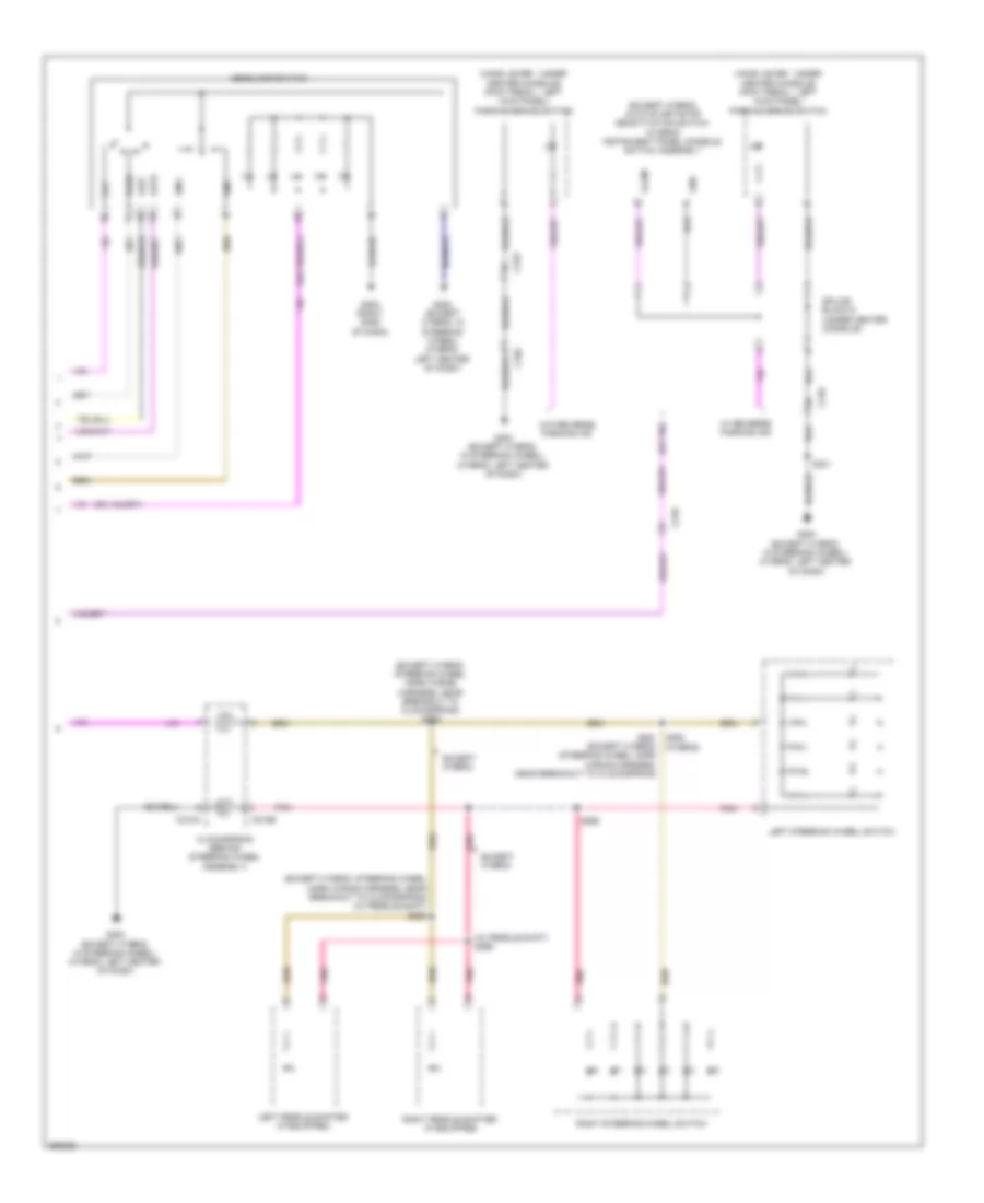
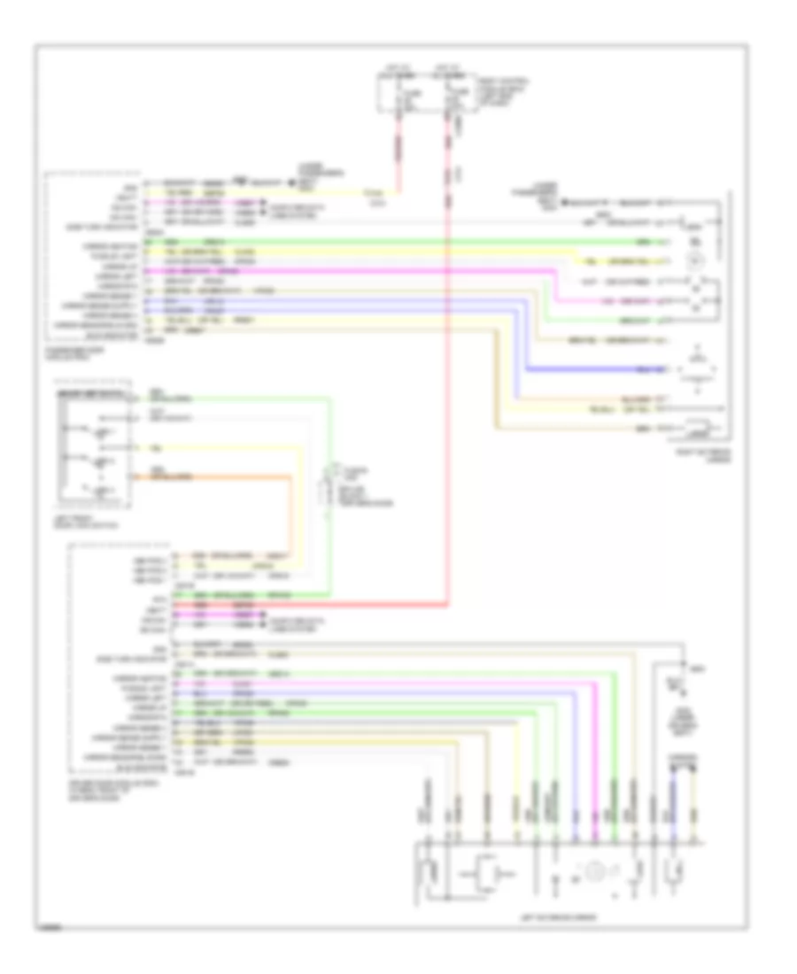
Defoggers Wiring Diagram for Ford Fusion SE 2013
List of elements for Defoggers Wiring Diagram for Ford Fusion SE 2013:
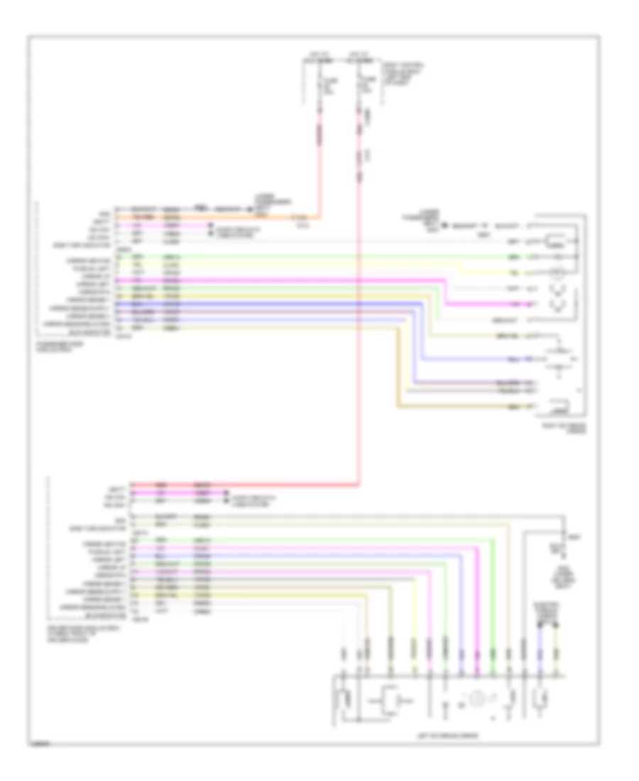
- (hybrid: front of driver's door) driver door module (ddm)
- (under driver's seat) g302
- Battery junction box (bjb) (left side of engine compt)
- Body control module (bcm) (left end of dash)
- C1035a
- C215
- C219
- C2280f
- C2402a
- C311 a16
- C312 a16
- C402a
- C402b
- C408
- C501a
- C501b
- C652a
- C652b
- Computer data lines system
- Crd02
- Crd13
- Except hybrid
- Front control interface module (center of dash)
- Fuse 30a
- Fuse 40a
- Fusion
- G303 (under passenger's seat)
- G401 (right side of luggage compt)
- Hot at all times
- Hot in run or start
- Htr
- Hybrid
- Left exterior mirror
- Mkz
- Ms can+
- Ms can-
- Nca
- Passenger door module (pdm)
- Rear heated window element
- Rear window defrost relay
- Red
- Right exterior mirror
- S500
- S600
- Sbp25
- Sbp26
- Vbatt
- Vdb06
- Vdb07
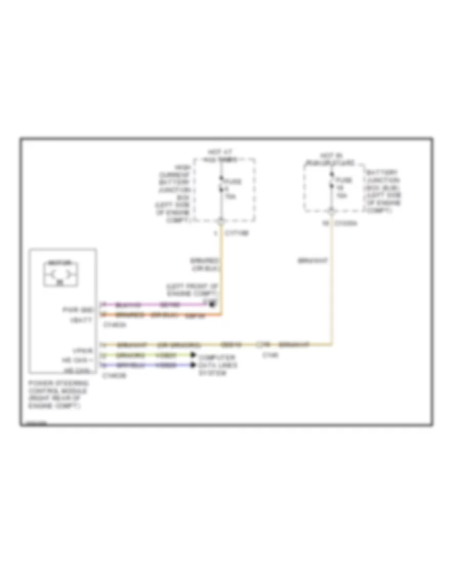
ELECTRONIC POWER STEERING
Electronic Power Steering Wiring Diagram, Except Hybrid for Ford Fusion SE 2013
List of elements for Electronic Power Steering Wiring Diagram, Except Hybrid for Ford Fusion SE 2013:
- (left front of engine compt) g107
- Battery junction box (bjb) (left side of engine compt)
- C1035a
- C146
- C1463a
- C1463b
- C1716b
- Cbb19
- Computer data lines system
- Fuse 10a
- Fuse 70a
- Gd192
- High current battery junction box (left side of engine compt)
- Hot at all times
- Hot in run or start
- Hs can +
- Hs can -
- Motor
- Power steering control module (right rear of engine compt)
- Pwr gnd
- Sbf06
- Vbatt
- Vdb25
- Vdb26
- Vpwr
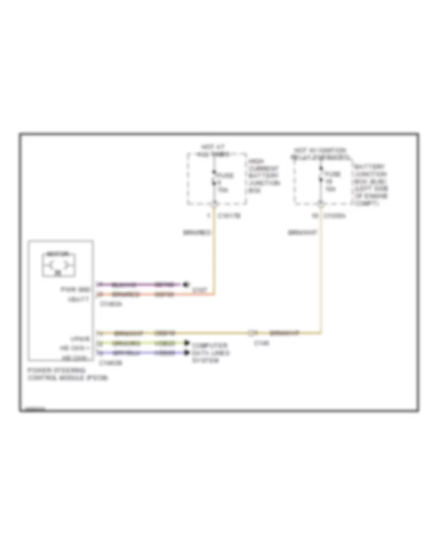
Electronic Power Steering Wiring Diagram, Hybrid for Ford Fusion SE 2013
List of elements for Electronic Power Steering Wiring Diagram, Hybrid for Ford Fusion SE 2013:
- Battery junction box (bjb) (left side of engine compt)
- C1035a
- C146
- C1463a
- C1463b
- C1617b
- Cbb19
- Computer data lines system
- Fuse 10a
- Fuse 70a
- G107
- Gd192
- High current battery junction box
- Hot at all times
- Hot w/ ignition relay energized
- Hs can +
- Hs can -
- Motor
- Power steering control module (pscm)
- Pwr gnd
- Sbf06
- Vbatt
- Vdb25
- Vdb26
- Vpwr
ELECTRONIC SUSPENSION
Electronic Suspension Wiring Diagram for Ford Fusion SE 2013
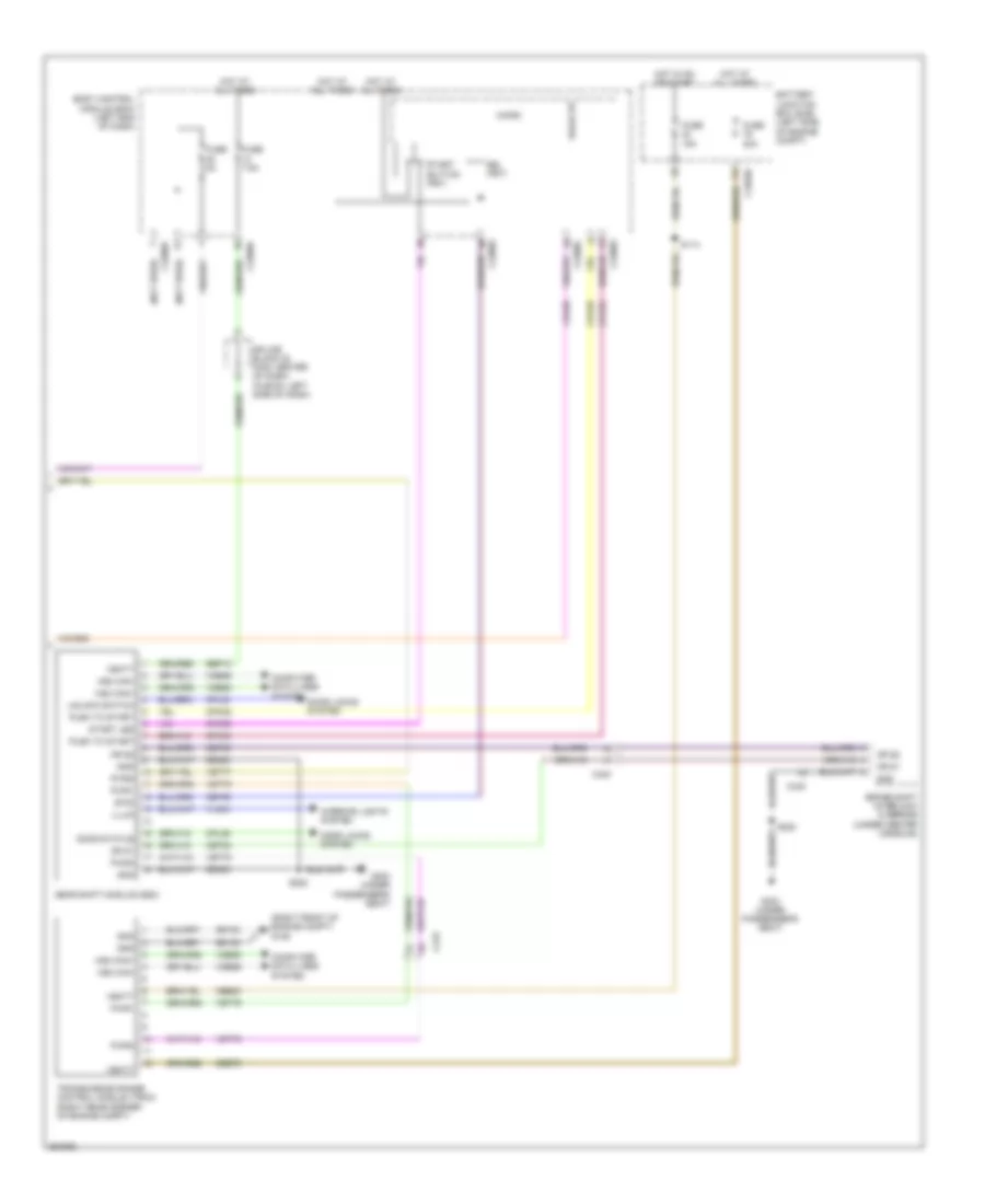
List of elements for Electronic Suspension Wiring Diagram for Ford Fusion SE 2013:
- (hybrid: engine controls sensor harness, near breakout to transmission range control module) (except hybrid: engine controls sensor harness, near breakout to left front height sensor)
- (on left front shock absorber assembly) (except hybrid) left front shock absorber (hybrid) left front hydraulic solenoid valve
- (on left rear shock absorber assembly) (except hybrid) left rear shock absorber (hybrid) left rear hydraulic solenoid valve
- Active dmpr fl hi
- Active dmpr fl lo
- Active dmpr fr hi
- Active dmpr fr lo
- Active dmpr rl hi
- Active dmpr rl lo
- Active dmpr rr hi
- Active dmpr rr lo
- Body control module (bcm) (left end of dash)
- C1010
- C215
- C2280f
- C3051
- C4396c
- C4396d
- Cbp36
- Ccd03
- Ccd04
- Ccd05
- Ccd06
- Computer data lines system
- Fl sig
- Fr sig
- Fuse 15a
- G401 (right side of luggage compt)
- Gd313
- Gnd
- Hot in run or start
- Hs can +
- Hs can -
- Isp-r
- Lcd02
- Lcd23
- Left front height sensor (in left front wheelwell)
- Left rear height sensor (in left rear wheelwell)
- Rcd02
- Rcd03
- Rcd04
- Rcd05
- Rcd06
- Rcd23
- Right front height sensor (in right front wheelwell)
- Right front hydraulic solenoid valve (hybrid) right front shock absorber (except hybrid) (on right front shock absorber assembly)
- Right rear height sensor (in right rear wheelwell)
- Right rear hydraulic solenoid valve (hybrid) right rear shock absorber (except hybrid) (on right rear shock absorber assembly)
- Rl sig
- Rr sig
- S121
- S122
- S323 (mkz)
- S417 (body main harness, near breakout to c3051)
- S418 (body main harness, near breakout to c3051)
- Sig gnd
- Vcd10
- Vcd11
- Vcd12
- Vcd13
- Vdb25
- Vdb26
- Vehicle dynamics module (vdm) (left side of luggage compt)
- Vref
ENGINE PERFORMANCE
1.6L TURBO
1.6L Turbo, Engine Performance Wiring Diagram, A/T (1 of 6) for Ford Fusion SE 2013
List of elements for 1.6L Turbo, Engine Performance Wiring Diagram, A/T (1 of 6) for Ford Fusion SE 2013:
- (engine controls sensor harness, near breakout to anti-lock brake system module) s120
- 10a
- Accr
- Air conditioning system
- Apprtn1
- Apprtn2
- Appvref1
- Appvref2
- Battery junction box (bjb) (left side of engine compt)
- C1010
- C1026
- C1035a
- C1035b
- C1232b
- C215
- C219
- C248
- C315
- Cact
- Canv
- Cbb26
- Cdc12
- Cdc15
- Cdc35
- Ce113
- Ce114
- Ce170
- Ce233
- Ce436
- Ce515
- Ce608
- Cec01
- Cec02
- Ch302
- Ch307
- Computer data lines system
- Cooling fans system
- Cpc
- Cr115
- Dc to dc converter control module (w/ auto start/ stop system) (right rear of engine compt)
- Eng start sig
- Evapcp
- Fp pwr
- Fp rtn
- Fpc
- Fpm
- Fuel lvl2
- Fuel pump (fp) assembly (top of fuel tank)
- Fuel pump control module (left front of luggage compt)
- Fuel pump relay
- Fuel rtn
- Fuel sndr
- Fuel vpwr
- Fuse
- Fuse 10a
- Fuse 15a
- Fuse 20a
- Fuse 30a
- G304 (left "c" pillar)
- Gd304
- Genmon
- Gnd
- Hfc
- Hot at all times
- Hot in on or start
- Hs 1 can +
- Hs 1 can -
- Hs3 can +
- Hs3 can -
- Htr12
- Ies
- Instrument panel cluster (ipc) module
- Isp r
- Le136
- Le137
- Le230
- Le423
- Le424
- Lfc
- Lin
- Nca
- Pcm power relay
- Pcm wake
- Powertrain control module (pcm)
- Re136
- Re137
- Re230
- Re242
- Re332
- Re406
- Re407
- Re515
- Return
- S415
- S419
- Sig
- Sigrtn
- Smc
- Sme
- Smr
- Starting/ charging system
- Vacc
- Vdb04
- Vdb05
- Vdn06
- Ve225
- Ve462
- Ve518
- Vref
1.6L Turbo, Engine Performance Wiring Diagram, A/T (2 of 6) for Ford Fusion SE 2013
List of elements for 1.6L Turbo, Engine Performance Wiring Diagram, A/T (2 of 6) for Ford Fusion SE 2013:
- (engine controls sensor harness, near breakout to coil on plug 3)
- (engine controls sensor harness, near breakout to pcm)
- (engine controls sensor harness, near breakout to pcm) s134
- (instrument panel wiring harness, near breakout to g202)
- (right front of engine compt) air conditioning (a/c) pressure transducer
- (right front of engine compt) turbocharger boost pressure/charge air cooler temperature (tcbp/cact) sensor
- (top of engine) fuel pressure sensor
- (top of fuel tank) fuel level sensor
- (top of fuel tank) fuel tank pressure (ftp) sensor
- Accelerator pedal position (app) sensor (left side of dash)
- C1010
- C145
- C146
- C1558a
- C315
- Cact
- G101 (left front of engine compt)
- Generator
- Intake air temperature (iat) sensor (left front of engine compt)
- Nca
- Pnk
- S119 (engine controls sensor harness, near breakout to anti- lock brake system module)
- S131 (engine controls sensor harness, near breakout to pcm)
- S133
- S204
- S205 (main wiring harness, in breakout to steering column control module)
- S214
- S216
- Selector lever assembly (center console)
- Sigrtn
- Sst rtn
- Sst+
- Sst-
- Stop lamp switch (under left side of dash)
- Tcbp
- Vref
1.6L Turbo, Engine Performance Wiring Diagram, A/T (3 of 6) for Ford Fusion SE 2013
List of elements for 1.6L Turbo, Engine Performance Wiring Diagram, A/T (3 of 6) for Ford Fusion SE 2013:
- (behind right end of front grille) ambient air temperature (aat) sensor
- (engine controls sensor harness, near breakout to coil on plug 3) s126
- (engine controls sensor harness, near breakout to g101) s112
- (not used)
- (on generator) generator current sensor
- Aat
- Acpt
- App1
- App2
- Bcs2 alt
- Body control module (bcm) (left end of dash)
- Bpp
- Bps
- C1232b
- C134
- C146
- C1617f
- C219
- C2280a
- C2280b
- C2280c
- C2280h
- Cbb07
- Ccb08
- Cdc10
- Cdc54
- Ce237
- Ce420
- Ce436
- Ces09
- Cet42
- Cet43
- Computer data lines system
- Evap
- Frd
- Ftp
- Fuel pump (fet)
- Fuel pump on (fet)
- Fuse 5a
- G104 (right side of engine compt)
- Gd113
- Gencom
- High current battery junction box (bjb) (left side of engine compt)
- Ho2s12
- Hot at all times
- Hs1 can+
- Hs1 can-
- Iat
- Mega fuse 125a
- Micro
- Pcm rc
- Powertrain control module (pcm)
- Pwr gnd
- Smcs
- Sst+
- Sst-
- Starting/ charging system
- Tcbp
- Vdb04
- Vdb05
- Vdc61
- Ve701
- Ve702
- Ve727
- Ve731
- Ve740
- Ve750
- Ve805
- Ve922
- Vh433
- Vpwr
1.6L Turbo, Engine Performance Wiring Diagram, A/T (4 of 6) for Ford Fusion SE 2013
List of elements for 1.6L Turbo, Engine Performance Wiring Diagram, A/T (4 of 6) for Ford Fusion SE 2013:
- (engine controls wiring
- (rear of engine) evaporative emission (evap) purge valve
- (rear of exhaust manifold) heated oxygen sensor (ho2s) 12
- (rear of exhaust manifold) universal heated oxygen sensor (ho2s) 11
- (right front of cylinder head) variable camshaft timing 12 (vct12) solenoid
- (top left front of cylinder head) variable camshaft timing 11 (vct11) solenoid
- (top right side of engine) fuel injection pump
- (under right rear of vehicle) evap canister vent valve
- Atfpc
- Atfpm
- C1010
- C1026
- C1232e
- Ce205
- Ce206
- Ce207
- Ce208
- Ce226
- Ce304
- Ce305
- Ce412
- Ce426
- Cet05
- Cet07
- Cet09
- Cet49
- Cmp12
- Cop2d
- Cop3b
- Electronic throttle control (etc)
- Evap purge valve
- Fvr
- Fvrrtn
- Harness, near breakout to knock sensor 2) s147
- Inj1
- Inj1rtn
- Inj2
- Inj2rtn
- Inj3
- Inj3rtn
- Inj4
- Inj4rtn
- Ks1+
- Ks1-
- Le451
- Lpc
- Nca
- Powertrain control module (pcm)
- Re205
- Re206
- Re207
- Re208
- Re226
- Re323
- Re405
- S113
- S315
- Sigrtn
- Ssa
- Ssc
- Tacm+
- Tacm-
- Tft
- Tp1
- Tp2
- Tspc
- Uo2s11
- Uo2spc11
- Ve707
- Ve801
- Ve818
- Ve819
- Ve826
- Vet27
- Vyt11
- Vyt12
1.6L Turbo, Engine Performance Wiring Diagram, A/T (5 of 6) for Ford Fusion SE 2013
List of elements for 1.6L Turbo, Engine Performance Wiring Diagram, A/T (5 of 6) for Ford Fusion SE 2013:
- (bottom
- (bottom right front of engine) turbocharger (tc) wastegate regulating valve solenoid
- (engine controls harness, near breakout to crankshaft position sensor) s151
- (left front of engine) engine coolant valve
- (left rear of engine) engine cooling bypass solenoid
- (left side of engine compt) transmission fluid pump
- (right front of engine compt) active grille shutter
- (top of engine, above respective cylinder)
- (top right side of engine)
- Batt
- C1026
- C1045
- C134
- C146
- Coil on plug (cop) 1
- Coil on plug (cop) 2
- Coil on plug (cop) 3
- Coil on plug (cop) 4
- Fuel injector
- G101 (left front of engine compt)
- G110 (left rear of engine)
- Gnd
- Knock sensor 1 (ks1) (left rear of engine)
- Power distribution system
- Pwr/diag
- Right side of engine) turbocharger bypass valve (tcby)
- Run/start
- S110
- S139
- S144
- S148
- Spd command
1.6L Turbo, Engine Performance Wiring Diagram, A/T (6 of 6) for Ford Fusion SE 2013
List of elements for 1.6L Turbo, Engine Performance Wiring Diagram, A/T (6 of 6) for Ford Fusion SE 2013:
- (battery cable wiring harness, in breakout to transmission)
- (engine control wiring harness, near breakout to knock sensor 2) s149
- (engine controls harness, near breakout knock sensor 2) s146
- (engine controls harness, near breakout to crankshaft position sensor) s150
- (lower right front of engine block) crankshaft position (ckp) sensor
- (near breakout to coil knock sensor 2) s145
- (right rear of cylinder head) engine coolant temperature (ect) sensor
- (top front of engine) fuel rail pressure (frp) sensor
- (top left front of engine) manifold absolute pressure (map) sensor
- (top left rear of cylinder head) camshaft position 11 (cmp11) sensor
- (top right rear of cylinder head) camshaft position 12 (cmp12) sensor
- 6f35 transmission (left side of transmission)
- C1232e
- C1520a
- C1520b
- Ce166
- Ce167
- Ce235
- Ce303
- Ce306
- Ce421
- Ce422
- Ce460
- Cet05
- Cet06
- Cet07
- Cet08
- Cet09
- Cet10
- Cet18
- Cet49
- Ckp
- Cmc24
- Cmp11
- Cop1a
- Cop4c
- Cvb
- Ect
- Etcref
- Etcrtn tss/oss/ tr gnd map
- Frp
- Knock sensor 2 (ks2) (left front of engine)
- Ks2+
- Ks2-
- Le111
- Le134
- Le238
- Le423
- Le448
- Le452
- Le458
- Lpc
- Oil pressure switch (left side of engine block)
- Ops
- Oss
- Oss/tr gnd
- Oss/tr vpwr
- Powertrain control module (pcm)
- Re134
- Re324
- Re454
- Ret24
- S142 (in breakout to transmission)
- S143
- Sigrtn
- Ssa
- Ssb
- Ssc
- Ssd
- Sse
- Tcby
- Tcc
- Tcwrvs
- Tft
- Tft sig rtn
- Tr-p
- Trs
- Tspc
- Tss
- Tss/gnd
- Tss/oss/ tr vpwr
- Tss/vpwr
- Uo2sgref11
- Uo2shtr11
- Uo2spct11
- Vct11
- Vct12
- Ve706
- Ve711
- Ve716
- Ve802
- Ve803
- Ve836
- Vet26
- Vet27
- Vet32
- Vet33
- Vref
1.6L Turbo, Engine Performance Wiring Diagram, M/T (1 of 7) for Ford Fusion SE 2013
List of elements for 1.6L Turbo, Engine Performance Wiring Diagram, M/T (1 of 7) for Ford Fusion SE 2013:
- Aat
- Accr
- Acpt
- Air conditioning
- Air conditioning system
- App1
- App2
- Apprtn 1
- Apprtn 2
- Appvref1
- Appvref2
- Battery junction box (bjb) (left side of engine compt)
- C1010
- C1026
- C1035a
- C1232b
- Cact
- Canv
- Cbb26
- Cdc12
- Cdc15
- Cdc35
- Ce113
- Ce114
- Ce170
- Ce233
- Ce237
- Ce436
- Cec01
- Cec02
- Cet47
- Ch302
- Ch307
- Computer data lines system
- Cooling fans system
- Cpc
- Cpp1
- Cpp2
- Cr115
- Dc to dc converter control module (w/ auto start/ stop system (right rear of engine compt)
- Evap canister vent valve (under right rear of vehicle)
- Evap purge valve
- Evapcp
- Exterior lights system
- Fpc
- Fpm
- Fuse 10a
- Fuse 15a
- Fuse 20a
- Genmon
- Hfc
- Ho2s12
- Hot at all times
- Hot in run or start
- Hsi can +
- Hsi can -
- Htr12
- Ies
- Ispr
- Le136
- Le137
- Le230
- Le423
- Le424
- Le456
- Le458
- Lfc
- Lin
- Pcm power relay
- Pcm rc
- Pcm-wake
- Powertrain control module (pcm)
- Re136
- Re137
- Re230
- Re242
- Re332
- Re335
- Re403
- Re407
- S110
- S113
- S315
- Sigrtn
- Smc
- Sme
- Smr
- Starting/charging system
- System
- Vacc
- Vdb04
- Vdb05
- Vdn06
- Ve225
- Ve462
- Ve518
- Ve701
- Ve702
- Ve731
- Ve750
- Ve757
- Vh433
- Vref
1.6L Turbo, Engine Performance Wiring Diagram, M/T (2 of 7) for Ford Fusion SE 2013
List of elements for 1.6L Turbo, Engine Performance Wiring Diagram, M/T (2 of 7) for Ford Fusion SE 2013:
- (behind right end of front grille) ambient air temperature (aat) sensor
- (engine controls sensor harness, near breakout to anti-lock brake system module)
- (engine controls sensor harness, near breakout to coil on plug 3)
- (engine controls sensor harness, near breakout to pcm)
- (on generator) generator current sensor
- (rear of exhaust manifold) heated oxygen sensor (ho2s) 12
- (right front of engine compt) a/c pressure transducer
- (right front of engine compt) turbocharger boost pressure/charge air coolant temperature (tcbp/cact) sensor
- Accelerator pedal position (app) sensor (left side of dash)
- C1010
- C1026
- C134
- C145
- C146
- C315
- Cact
- Clutch master cylinder push rod position sensor (on clutch master cylinder)
- Cpp1
- Cpp2
- Fuel pressure sensor (top of engine)
- Fuel tank pressure sensor (top of fuel tank)
- Nca
- S119
- S126
- S131
- S133
- S134
- Sigrtn
- Tcbp
- Vref
1.6L Turbo, Engine Performance Wiring Diagram, M/T (3 of 7) for Ford Fusion SE 2013
List of elements for 1.6L Turbo, Engine Performance Wiring Diagram, M/T (3 of 7) for Ford Fusion SE 2013:
- Bcs2alt
- Bpp
- Bps
- C1232b
- C146
- C1558a
- Cbb07
- Ccb08
- Cdc10
- Cdc54
- Ce420
- Ces09
- Computer data lines system
- Electronic throttle control (etc)
- Evap
- Exterior lights system
- Frp
- Ftp
- G101 (left front of engine compt)
- G104 (right side of engine compt)
- Gd113
- Gencom
- Generator
- Hs1 can +
- Hs1 can -
- Iat
- Knock sensor 1 (ks1) (left rear of engine)
- Knock sensor 2 (ks2) (left front of engine)
- Powertrain control module (pcm)
- Pwrgnd
- S112
- S204 (engine controls sensor harness, near breakout to coil on plug 3)
- Smcs
- Starting/ system charging
- Stop lamp switch (under left side of dash)
- Tcbp
- Vdb04
- Vdb05
- Vdc61
- Ve727
- Ve740
- Ve805
- Ve922
- Vpwr
1.6L Turbo, Engine Performance Wiring Diagram, M/T (4 of 7) for Ford Fusion SE 2013
List of elements for 1.6L Turbo, Engine Performance Wiring Diagram, M/T (4 of 7) for Ford Fusion SE 2013:
- (left front of engine compt) intake air temperature sensor
- (rear of engine) evaporative emission (evap) purge valve
- (rear of exhaust manifold) universal heated oxygen sensor (ho2s) 11
- (right front of cylinder head) variable camshaft timing 12 (vct12) solenoid
- (top left front of cylinder head) variable camshaft timing 11 (vct11) solenoid
- C1026
- C1232e
- Ce205
- Ce206
- Ce207
- Ce208
- Ce226
- Ce412
- Ce426
- Fvr
- Fvrrtn
- Inj1
- Inj1 rtn
- Inj2
- Inj2 rtn
- Inj3
- Inj3 rtn
- Inj4
- Inj4 rtn
- Ks1+
- Ks1-
- Ks2+
- Ks2-
- Nca
- Powertrain control module (pcm)
- Re205
- Re206
- Re207
- Re208
- Re226
- Re323
- Re324
- S147
- Tacm+
- Tacm-
- Ve801
- Ve802
1.6L Turbo, Engine Performance Wiring Diagram, M/T (5 of 7) for Ford Fusion SE 2013
List of elements for 1.6L Turbo, Engine Performance Wiring Diagram, M/T (5 of 7) for Ford Fusion SE 2013:
- (left side of dash) clutch pedal position switch (cpp)
- (top right side of engine)
- Battery junction box (bjb) (left side of engine compt)
- Body control module (left end of dash)
- C1010
- C1035a
- C1045
- C1617f
- C215
- C219
- C2280a
- C2280b
- C2280c
- C2280g
- C315
- Can - hs1
- Ce515
- Ce608
- Computer data lines system
- Fp pwr
- Fp rtn
- Fpc
- Fpm
- Fuel injector
- Fuel pump (fet)
- Fuel pump assembly (top of fuel tank)
- Fuel pump control module (left front of luggage compt)
- Fuel pump on (fet)
- Fuel pump relay
- Fuse 30a
- G101 (left front of engine compt)
- G304 (left "c" pillar)
- Gd304
- Gnd
- High current battery junction box (bjb) (left side of engine compt)
- Hot at all times
- Hs1 can +
- Mega fuse 125a
- Micro
- Nca
- Re515
- S120
- S415
- S419
- Vdb04
- Vdb05
- Ve225
- Ve518
- Vpwr
1.6L Turbo, Engine Performance Wiring Diagram, M/T (6 of 7) for Ford Fusion SE 2013
List of elements for 1.6L Turbo, Engine Performance Wiring Diagram, M/T (6 of 7) for Ford Fusion SE 2013:
- (engine control wiring harness, near breakout to knock sensor 2)
- (left front of engine) manifold absolute pressure (map) sensor
- (left rear of engine) camshaft position (cmp) sensor 11
- (left side of engine) fuel rail pressure (frp) sensor
- (right rear of cylinder head) engine coolant temperature (ect) sensor
- (right rear of engine) camshaft position (cmp) sensor 12
- (right side of engine) crankshaft position (ckp) sensor
- C1026
- C248
- C315
- Computer data lines system
- Engine coolant valve (left front of engine)
- Engine cooling bypass solenoid (left rear of engine)
- Fuel injection pump (top right side of engine)
- Fuel level sensor (top of fuel tank)
- Fuel lvl 2
- Fuel rtn
- Fuel snd
- Instrument panel cluster module (ipc)
- Ms3 can +
- Ms3 can -
- Pnk
- Return
- S145
- S146
- S149
- S150 (engine controls harness, near breakout to crankshaft position sensor)
- S151
- S152
- Sig
- Turbocharger bypass valve (tcby) (bottom right side of engine)
- Turbocharger wastegate regulating valve solenoid (bottom right side of engine)
1.6L Turbo, Engine Performance Wiring Diagram, M/T (7 of 7) for Ford Fusion SE 2013
List of elements for 1.6L Turbo, Engine Performance Wiring Diagram, M/T (7 of 7) for Ford Fusion SE 2013:
- C1232e
- Ce166
- Ce167
- Ce235
- Ce303
- Ce304
- Ce305
- Ce306
- Ce421
- Ce422
- Ce460
- Ckp
- Cmc24
- Cmp11
- Cmp12
- Coil on plug (cop) 1
- Coil on plug (cop) 2
- Coil on plug (cop) 3
- Coil on plug (cop) 4
- Cop1a
- Cop2d
- Cop3b
- Cop4c
- Cvb
- Ect
- Etcref
- Etcrtn
- Frp
- G110 (left rear of engine)
- Le134
- Le238
- Le423
- Le448
- Le451
- Le452
- Le458
- Map
- Oil pressure switch (left side of engine block)
- Ops
- Powertrain control module (pcm)
- Re134
- Re238
- Re405
- Re429
- Re433
- Re454
- S144
- S148
- Sigrtn
- Tcby
- Tcwrvs
- Tp1
- Tp2
- Uo2s11
- Uo2sgref11
- Uo2shtr11
- Uo2spc11
- Uo2spct11
- Vct11
- Vct12
- Ve706
- Ve707
- Ve711
- Ve716
- Ve803
- Ve818
- Ve819
- Ve826
- Ve836
- Vref
2.0L FLEX FUEL
2.0L Flex Fuel, Engine Performance Wiring Diagram (1 of 6) for Ford Fusion SE 2013
List of elements for 2.0L Flex Fuel, Engine Performance Wiring Diagram (1 of 6) for Ford Fusion SE 2013:
- (engine controls sensor harness, near breakout to anti-lock brake system module) s120
- 10a
- Accr
- Air conditioning system
- Apprtn1
- Apprtn2
- Appvref1
- Appvref2
- Awd-m
- Battery junction box (bjb) (left side of engine compt)
- C1010
- C1026
- C1035a
- C1381b
- C215
- C219
- C248
- C315
- Cact
- Cbb26
- Cdc12
- Cdc15
- Cdc35
- Ce113
- Ce233
- Ce436
- Ce515
- Ce608
- Cec01
- Cec02
- Ch302
- Computer data lines system
- Cooling fans system
- Cr115
- Evapcp
- Fp pwr
- Fp rtn
- Fpc
- Fpm
- Fuel lvl2
- Fuel pump (fp) assembly (top of fuel tank)
- Fuel pump control module (left front of luggage compt)
- Fuel pump relay
- Fuel rtn
- Fuel sndr
- Fuse
- Fuse 10a
- Fuse 15a
- Fuse 20a
- Fuse 30a
- G304 (left "c" pillar)
- Gd304
- Genmon
- Gnd
- Hfc
- Hot at all times
- Hot in start or run
- Hs3 can +
- Hs3 can -
- Htr12
- Ies
- Instrument panel cluster (ipc) module
- Isp-r
- Le136
- Le137
- Le230
- Le423
- Le424
- Lfc
- Lin
- Nca
- Pcm power relay
- Pcm wake
- Powertrain control module (pcm)
- Re136
- Re137
- Re230
- Re242
- Re332
- Re406
- Re407
- Re515
- Return
- S415
- S419
- Sig
- Sigrtn
- Smc
- Smr
- Starting/ charging system
- Transmissions system
- Vacc
- Vcf34
- Vdn06
- Ve225
- Ve462
- Ve518
- Vpwr
- Vref
2.0L Flex Fuel, Engine Performance Wiring Diagram (2 of 6) for Ford Fusion SE 2013
List of elements for 2.0L Flex Fuel, Engine Performance Wiring Diagram (2 of 6) for Ford Fusion SE 2013:
- (engine controls sensor harness, near breakout to anti- lock brake system module)
- (engine controls sensor harness, near breakout to pcm)
- (engine controls sensor harness, near breakout to pcm) s134
- (instrument panel wiring harness, near breakout to g202)
- (right front of engine compt) air conditioning (a/c) pressure transducer
- (right front of engine compt) turbocharger boost pressure/charge air cooler temperature (tcbp/cact) sensor
- (top of engine) fuel pressure sensor
- (top of fuel tank) fuel level sensor
- (top of fuel tank) fuel tank pressure (ftp) sensor
- Accelerator pedal position (app) sensor (left side of dash)
- C1010
- C145
- C218b
- C218c
- C2414a
- C2414d
- C315
- Cact
- Cet42
- Cet43
- Clockspring (behind steering wheel assembly)
- Computer data lines system
- G101 (left front of engine compt)
- Hs2 can+
- Hs2 can-
- Intake air temperature (iat) sensor (left front of engine compt)
- Nca
- Nca sst rtn
- Nca sst+
- Pnk
- Re407
- S119
- S131 (engine controls sensor harness, near breakout to pcm)
- S133
- S204
- S205
- S214
- S216
- Selector lever assembly (fusion) (center console)
- Sigrtn
- Sst-
- Steering column control module (sccm) (on steering column)
- Stop lamp switch (under left side of dash)
- Tcbp
- Vdb25
- Vdb26
- Vref
2.0L Flex Fuel, Engine Performance Wiring Diagram (3 of 6) for Ford Fusion SE 2013
List of elements for 2.0L Flex Fuel, Engine Performance Wiring Diagram (3 of 6) for Ford Fusion SE 2013:
- (behind right end of front grille) ambient air temperature (aat) sensor
- (engine controls sensor harness, near breakout to coil on plug 3) s126
- (not used)
- (on generator) generator current sensor
- Aat
- Acpt
- App1
- App2
- Awd-c
- Bcs2 alt
- Body control module (bcm) (left end of dash)
- Bpp
- Bps
- C134
- C1381b
- C146
- C1716f
- C219
- C2280a
- C2280b
- C2280c
- C2280h
- Cbb07
- Ccb08
- Cdc10
- Cdc54
- Ce226
- Ce237
- Ce420
- Ce436
- Ces09
- Cet42
- Cet43
- Computer data lines system
- Cr115
- Evap
- Flp
- Ftp
- Fuel pump (fet)
- Fuel pump on (fet)
- Fuse 5a
- G104 (right side of engine compt)
- Gd113
- Gear shift module (gsm) (upper center of dash)
- Gencom
- High current battery junction box (bjb) (left side of engine compt)
- Ho2s12
- Hot at all times
- Hs1 can+
- Hs1 can-
- Iat
- Mega fuse 125a
- Micro
- Nca
- Pcm rc
- Powertrain control module (pcm)
- Pwr 2
- Pwr gnd
- S112
- Smcs
- Sst+
- Sst-
- Starting/charging system
- Tcbp
- Transmissions system
- Vcf35
- Vdb04
- Vdb05
- Vdc61
- Ve701
- Ve702
- Ve727
- Ve731
- Ve740
- Ve750
- Ve805
- Ve922
- Vet77
- Vh433
- Vpwr
2.0L Flex Fuel, Engine Performance Wiring Diagram (4 of 6) for Ford Fusion SE 2013
List of elements for 2.0L Flex Fuel, Engine Performance Wiring Diagram (4 of 6) for Ford Fusion SE 2013:
- (engine controls harness, near breakout to coil on plug 1) s147
- (not used)
- (not used) c1026
- (rear of exhaust manifold) heated oxygen sensor (ho2s) 12
- (rear of exhaust manifold) universal heated oxygen sensor (ho2s) 11
- (top front of cylinder head) variable camshaft timing 11 (vct11) solenoid
- (top front of cylinder head) variable camshaft timing 12 (vct12) solenoid
- (top rear of engine) evaporative emission (evap) purge valve
- (top rear of engine) fuel injection pump
- Atfpc
- Atfpm
- C1010
- C1026
- C1381e
- Ce205
- Ce206
- Ce207
- Ce208
- Ce226
- Ce304
- Ce305
- Ce412
- Ce426
- Cet05
- Cet07
- Cet09
- Cet49
- Cmp12
- Cop2d
- Cop3b
- Electronic throttle control (etc) (on throttle body)
- Evap purge valve
- Fvr
- Fvrrtn
- Inj1
- Inj1rtn
- Inj2
- Inj2rtn
- Inj3
- Inj3rtn
- Inj4
- Inj4rtn
- Ks1+
- Ks1-
- Le451
- Lpc
- Nca
- Powertrain control module (pcm)
- Re205
- Re206
- Re207
- Re208
- Re226
- Re323
- Re405
- S113
- Sigrtn
- Ssa
- Ssc
- Tacm+
- Tacm-
- Tft
- Tp1
- Tp2
- Tspc
- Uo2s11
- Uo2spc11
- Ve707
- Ve801
- Ve818
- Ve819
- Ve826
- Vet27
- Vyt11
- Vyt12
2.0L Flex Fuel, Engine Performance Wiring Diagram (5 of 6) for Ford Fusion SE 2013
List of elements for 2.0L Flex Fuel, Engine Performance Wiring Diagram (5 of 6) for Ford Fusion SE 2013:
- (engine controls harness, near breakout to crankshaft position sensor) s151
- (if equipped) left paddle shifter
- (if equipped) right paddle shifter
- (lower right front of engine) turbocharger (tc) wastegate regulating valve solenoid
- (right front of engine compt) active grille shutter
- (steering wheel horn wiring harness, near breakout to clockspring) s296
- (top center of engine) turbocharger bypass valve (tcby)
- (top left side of engine )
- (top of engine, above respective cylinder)
- (upper right side of engine) cylinder head temperature (cht) sensor
- C1026
- C1033
- C134
- Coil on plug (cop) 1
- Coil on plug (cop) 2
- Coil on plug (cop) 3
- Coil on plug (cop) 4
- Distribution system
- Fuel injector
- G110 (right front of engine)
- Interior lights system
- Knock sensor 1 (ks1)
- Nca
- Pnk
- S110
- S144
- S148
- S293
- S294
2.0L Flex Fuel, Engine Performance Wiring Diagram (6 of 6) for Ford Fusion SE 2013
List of elements for 2.0L Flex Fuel, Engine Performance Wiring Diagram (6 of 6) for Ford Fusion SE 2013:
- (engine controls harness, near breakout to coil on plug 1) s146
- (engine controls harness, near breakout to manifold absolute pressure sensor) s149
- (engine controls harness, near breakout to transmission)
- (engine controls harness, near breakout to variable camshaft timing 12 solenoid) s150
- (lower right front of engine block) crankshaft position (ckp) sensor
- (near breakout to coil on plug 4) s145
- (not used)
- (right rear of cylinder head) engine coolant temperature (ect) sensor
- (top front of engine) fuel rail pressure (frp) sensor
- (top left front of engine) manifold absolute pressure (map) sensor
- (top left rear of cylinder head) camshaft position 11 (cmp11) sensor
- (top left rear of cylinder head) camshaft position 12 (cmp12) sensor
- 6f35 transmission (con c1520a: left side of transmission) (con c1520b: rear of transmission)
- C1026
- C1033
- C1381e
- C1520a
- C1520b
- Ce148
- Ce235
- Ce239
- Ce303
- Ce306
- Ce421
- Ce422
- Ce460
- Cet05
- Cet06
- Cet07
- Cet08
- Cet09
- Cet10
- Cet18
- Cet49
- Cht
- Ckp
- Cmc24
- Cmp11
- Cop1a
- Cop4c
- Ect
- Etcref
- Etcrtn tss/oss/ tr gnd map
- Frp
- Knock sensor 2 (ks2) (left rear of engine)
- Ks2+
- Ks2-
- Le111
- Le134
- Le238
- Le423
- Le448
- Le452
- Le458
- Lpc
- Oil pressure switch (oil filter housing)
- Ops
- Oss
- Oss/tr gnd
- Oss/tr vpwr
- Pm htr
- Powertrain control module (pcm)
- Re134
- Re324
- Re454
- Ret24
- S142 (engine controls harness, near breakout to transmission)
- S143
- Sigrtn
- Ssa
- Ssb
- Ssc
- Ssd
- Sse
- Tcby
- Tcc
- Tcwrvs
- Tft
- Tft sig rtn
- Tr-p
- Trs
- Tspc
- Tss
- Tss/gnd
- Tss/oss/ tr vpwr
- Tss/vpwr
- Uo2sgref11
- Uo2shtr11
- Uo2spct11
- Vct11
- Vct12
- Ve706
- Ve711
- Ve712
- Ve716
- Ve802
- Ve803
- Vet26
- Vet27
- Vet32
- Vet33
- Vref
2.0L HYBRID
2.0L Hybrid, Engine Performance Wiring Diagram (1 of 9) for Ford Fusion SE 2013
List of elements for 2.0L Hybrid, Engine Performance Wiring Diagram (1 of 9) for Ford Fusion SE 2013:
- Aat
- Acc run
- Accelerator pedal position (app) sensor (on accelerator pedal bracket)
- Acpt
- Air conditioning system
- Air conditioning system trunk, tailgate, fuel doors system
- App1
- App2
- Apprtn1
- Apprtn2
- Appvref1
- Appvref2
- Battery junction box (left side of engine compt)
- Bpp
- Bps
- C1010
- C1026
- C1035a
- C1458a
- C175b
- C219
- Cbb07
- Cbb26
- Ccb08
- Cdc35
- Ce204
- Ce229
- Ce237
- Ce436
- Ces09
- Cet34
- Ch116
- Computer data lines system
- Cooling fans system
- Cto
- Ecby
- Ect2
- Engine coolant temperature sensor 2 (ect2) (phev)
- Evapldp
- Evapldppr
- Evaporative emission (evap) leak detection control module
- Fcv
- Ffdp
- Fpc
- Fpm
- Ftp
- Fuel pump (fp) relay
- Fuse 10a
- Fuse 15a
- Fuse 20a
- Fuse 30a
- G105 (right side of engine compt)
- Gd113
- Heater core shutoff (right rear of engine compt)
- Hot at all times
- Hs can+
- Hs can-
- Ignition relay
- Ignition switch
- Isp r
- Le136
- Le137
- Le230
- Le423
- Off
- Pcm power relay
- Pcmrc
- Powertrain control module (right rear of engine compt)
- Pwr gnd
- Pwr2
- Re136
- Re137
- Re141
- Re230
- Re259
- Re406
- Re407
- S112
- S113
- S315
- Secondary on board diagnostic module c/ transmission control module (left side of engine compt)
- Shift interlock system
- Sigrtn
- Start
- Tcs
- Transmissions system
- Vdb04
- Vdb05
- Ve203
- Ve225
- Ve518
- Ve701
- Ve702
- Ve716
- Ve750
- Ve922
- Ve934
- Vet76
- Vh433
- Vmc02
- Vpwr
- Vref
- Wake
2.0L Hybrid, Engine Performance Wiring Diagram (2 of 9) for Ford Fusion SE 2013
List of elements for 2.0L Hybrid, Engine Performance Wiring Diagram (2 of 9) for Ford Fusion SE 2013:
- (left "c" pillar)
- (right front of engine compt) air conditioning pressure transducer
- (top of fuel tank) fuel pump assembly
- (top of fuel tank) fuel tank pressure (ftp) sensor
- (top of valve cover)
- Body control module (left end of dash)
- C1010
- C145
- C215
- C2280c
- C2280h
- C315
- Cdc35
- Cdc55
- Ce436
- Ce515
- Ce608
- Ecm wake
- Exterior lights system
- Fpc
- Fpm
- Fppwr
- Fprtn
- Fuel pump (fet)
- Fuel pump control module
- G304 (left "c" pillar)
- Gd304
- Gnd
- Ign rly ctrl
- Ignition coil on plug 1
- Ignition coil on plug 2
- Ignition coil on plug 3
- Ignition coil on plug 4
- Ignition transformer capacitor (top center of engine)
- Instrument cluster system
- Micro
- Nca
- Re515
- S119 (engine controls sensor harness, near breakout to abs module)
- S144
- S204 (engine controls sensor harness, near breakout to c1010)
- Start
- Stop lamp switch (under left side of dash)
- Ve225
- Ve518
- Vpwr fuel
2.0L Hybrid, Engine Performance Wiring Diagram (3 of 9) for Ford Fusion SE 2013
List of elements for 2.0L Hybrid, Engine Performance Wiring Diagram (3 of 9) for Ford Fusion SE 2013:
- (left front of engine) knock sensor 1
- (left rear of engine) knock sensor 2
- (lower right front of engine block) crankshaft position sensor
- (phev) fuel tank isolation valve
- C1010
- C1026
- C146
- C175t
- Ce303
- Ce304
- Ce305
- Ckp
- Cop1a
- Cop2d
- Cop3b
- Cop4c
- Evaporative emission (evap) vapor blocking valve
- G105 (right side of engine compt)
- Gd113
- Gnd
- Hf35 transmission
- Ks 1+
- Ks 1-
- Ks 2+
- Ks 2-
- Le459
- Let57
- Powertrain control module (right rear of engine compt)
- Re135
- Re323
- Re324
- Ret57
- Sirtn
- Tr a1 sig
- Tr a2 sig
- Tr ref
- Tr rtn
- Ve711
- Ve801
- Ve802
- Vet56
- Vet57
- Vref
2.0L Hybrid, Engine Performance Wiring Diagram (4 of 9) for Ford Fusion SE 2013
List of elements for 2.0L Hybrid, Engine Performance Wiring Diagram (4 of 9) for Ford Fusion SE 2013:
- (at charge port) (phev) charge port light ring
- (rear of left front fender) (phev) charge port
- 40a
- Batt
- Battery charger control module (bccm) (phev)
- Battery junction box (left side of engine compt)
- Body control module (left end of dash)
- C1035a
- C1035b
- C1824
- C215
- C2280f
- C4455a
- C4455b
- Cbb29
- Computer data lines system
- Cyb55
- Cyb56
- Cyd14
- Fan fb
- Fan pwm
- Fuse 10a
- Fuse 15a
- Fuse 40a
- G101 (left front of engine compt)
- G113 (base of left "a" pillar)
- G400 (left side of luggage compt)
- Gnd
- High voltage battery charger cooling fan (phev) (left rear of luggage compt)
- High voltage battery cooling fan (left side of luggage compt)
- Hot at all times
- Hs can+
- Hs can-
- Hv (+)
- Hv (-)
- Hyb53
- Hyb54
- Inline fuse 1
- Inline fuse 2
- Red
- Resistor
- Ryb57
- S999
- Sbb57
- Vbatt
- Vdb04
- Vdb05
- Vpwr
- Vyb18
- Vyb19
- Wake
2.0L Hybrid, Engine Performance Wiring Diagram (5 of 9) for Ford Fusion SE 2013
List of elements for 2.0L Hybrid, Engine Performance Wiring Diagram (5 of 9) for Ford Fusion SE 2013:
- (left side of engine compt) high voltage battery junction box
- (mkz: near breakout to c495) (fusion: near breakout to luggage compt lid latch) s407
- (or hs/can+)
- (or hs/can-) hs/can+
- (or vdb04) vdb05
- (phev) charge cooling actuator
- Battery energy control module (becm) (behind left side of rear seat)
- Body control module (left end of dash)
- C215
- C2280d
- C4236b
- C4236c
- C4237a
- C4237b
- C4815b
- C4815c
- C4815d
- C4815e
- C4816b
- C495
- Cbb52
- Computer data lines system
- Cont pwr en
- Cr167
- Cs aout2
- Cs rtn
- Cs vref
- Ctrl
- Cyb03
- Cyb04
- Cyb10
- Cyb12
- Cyb13
- Cyc03
- Cyc04
- Cyc05
- Cyc06
- Cyc07
- Cyc08
- Cyc09
- Cyd14
- Dcdc wkup
- Ens
- Fan fb
- Fan pwm
- Feedback
- Fhev
- G400 (left side of luggage compt)
- Gd347
- Gnd
- High voltage traction battery temperature sensor
- Hs can+
- Hs can-
- Hs/can-
- Int+
- Int-
- Lines system computer data
- Lyc01
- Mc+ ctrl
- Mc-ctrl
- Micro
- Motor +
- Motor -
- Phev
- Prc ctrl
- Pwr gnd
- Red
- Ryb07
- Ryc01
- S235
- S415 (near breakout to c315)
- Sbf04
- Sbp14
- Temp rtn
- Temp sig
- Vbatt
- Vdb04
- Vdb04 (or vdb05)
- Vdb05
- Vpwr
- Vyb07
- Vyb18
- Vyb19
- Vyc02
- Wake
2.0L Hybrid, Engine Performance Wiring Diagram (6 of 9) for Ford Fusion SE 2013
List of elements for 2.0L Hybrid, Engine Performance Wiring Diagram (6 of 9) for Ford Fusion SE 2013:
- (left side of engine compt) (phev) high voltage battery junction box
- (left side of engine compt) dual battery fuse assembly
- (not used)
- 200a
- 30a
- Battery
- Battery junction box (left side of engine compt)
- Battery monitoring sensor (left rear of luggage compt)
- C1035b
- C1035c
- C1458a
- C1458e
- C1458g
- C1617a
- C1617e
- C1617k
- C1815a
- C1815b
- C4000
- C4001
- C4002
- C4453a
- C4453b
- C4453c
- C4453d
- C4815a
- C4815f
- C4815g
- C4815h
- Cabin coolant heater
- Cbb51
- Ce613
- Computer data lines system
- Cyd14
- Dc/dc converter module (phev)
- Dcdc wkup
- Fuse 15a
- G404 (left rear of luggage compt)
- Hdc52
- Hdc53
- High current battery junction box (bjb)
- High voltage battery
- High voltage battery service disconnect
- High voltage high current fuse
- Hot at all times
- Hs can+
- Hs can-
- Hv batt+
- Hv batt-
- Hv+
- Hv-
- Hyt01
- Hyt02
- Int+
- Int-
- Mega fuse 275a
- Midi fuse pnk 200a
- Midi fuse white 120a
- Nca
- Positive pack relay
- Red
- S107
- Sbf08
- Sdc02
- Secondary on board diagnostic module c/ transmission control module (left side of engine compt)
- Tcm power relay
- Tcmrc
- Vbatt
- Vdb04
- Vdb05
- Vpwr
2.0L Hybrid, Engine Performance Wiring Diagram (7 of 9) for Ford Fusion SE 2013
List of elements for 2.0L Hybrid, Engine Performance Wiring Diagram (7 of 9) for Ford Fusion SE 2013:
- Battery compartment thermistor 1
- Battery compartment thermistor 10
- Battery compartment thermistor 2
- Battery compartment thermistor 3
- Battery compartment thermistor 4
- Battery compartment thermistor 5
- Battery compartment thermistor 6
- Battery compartment thermistor 7
- Battery compartment thermistor 8
- Battery compartment thermistor 9
- Battery energy control module (becm) (behind left side of rear seat)
- Body control module (left end of dash)
- C2280d
- C4237c
- C4237d
- Lin 8
- Micro
- Ryb33
- Ryb34
- Ryb35
- Ryb36
- Ryb37
- Ryb38
- Ryb39
- Ryb40
- Ryb41
- Ryb42
- Temp rtn
- Temp sig
- Vdn03
- Vyb33
- Vyb34
- Vyb35
- Vyb36
- Vyb37
- Vyb38
- Vyb39
- Vyb40
- Vyb41
- Vyb42
2.0L Hybrid, Engine Performance Wiring Diagram (8 of 9) for Ford Fusion SE 2013
List of elements for 2.0L Hybrid, Engine Performance Wiring Diagram (8 of 9) for Ford Fusion SE 2013:
- (exhaust manifold) universal heated oxygen sensor (ho2s) 11
- (on throttle body) electronic throttle control (etc) module
- (top center of cylinder head) cylinder head temperature sensor
- Evaporative emission (evap) purge valve (left rear of engine)
- Heated oxygen sensor (ho2s) 12 (exhaust manifold)
- Nca
- Variable camshaft timing (vct11) solenoid 11 (top front of cylinder head)
2.0L Hybrid, Engine Performance Wiring Diagram (9 of 9) for Ford Fusion SE 2013
List of elements for 2.0L Hybrid, Engine Performance Wiring Diagram (9 of 9) for Ford Fusion SE 2013:
- (left side of engine) manifold absolute pressure sensor
- (on top of the engine, left of fuel injector 4 breakout)
- (top of engine)
- (top rear of engine) egr stepper motor
- C1026
- C175e
- Cabin heater coolant pump
- Ce101
- Ce102
- Ce103
- Ce104
- Ce113
- Ce205
- Ce206
- Ce207
- Ce208
- Ce233
- Ce235
- Ce412
- Ce420
- Ce421
- Ce426
- Ce622
- Ce908
- Ch307
- Cht
- Coil 1
- Coil 2
- Coil 3
- Coil 4
- Cooling fans system
- Cpc
- Digital
- Egrmc1
- Egrmc2
- Egrmc3
- Egrmc4
- Etcref
- Etcrtn
- Evapcp
- Evapldpsv
- Ffduc
- Fuel injector
- Ho2s12
- Htr12
- Iat
- Inj1
- Inj2
- Inj3
- Inj4
- Le134
- Le423
- Le448
- Le451
- Le452
- Lin
- Maf
- Map
- Mass air flow/intake air temperature (maf/iat) sensor (on throttle body)
- Oil pressure switch (oil filter housing)
- Ops
- Powertrain control module (right rear of engine compt)
- Pwm
- Re134
- Re320
- Re329
- Re405
- Re406
- S120
- S147
- S153
- Sigrtn
- Tacm+
- Tacm-
- Tp1
- Tp2
- Trunk, tailgate, fuel doors system
- Uo2s11
- Uo2shtr11
- Uo2spc11
- Uo2spct11
- Vbv
- Vct11
- Vdn06
- Ve712
- Ve731
- Ve740
- Ve803
- Ve807
- Ve818
- Ve819
- Ve826
- Vref
- Vref 5v
2.5L
2.5L, Engine Performance Wiring Diagram (1 of 5) for Ford Fusion SE 2013
List of elements for 2.5L, Engine Performance Wiring Diagram (1 of 5) for Ford Fusion SE 2013:
- (near breakout to coil on plug 3) s126
- 15a
- 20a
- Aat
- Accr
- Acpt
- Air conditioning pressure transducer (right front of engine compt)
- Air conditioning system
- Ambient air temperature sensor (behind right end of front grille)
- App1
- App2
- Apprtn1
- Apprtn2
- Appvref1
- Appvref2
- Battery junction box (bjb) (left side of engine compt)
- Bcs2 alt
- Bpp
- Bps
- C1010
- C1035a
- C134
- C145
- C146
- C1551b
- C219
- C2414a
- C315
- Canv
- Cbb07
- Cbb26
- Cbb49
- Ccb08
- Cdc10
- Cdc12
- Cdc15
- Cdc35
- Cdc54
- Ce114
- Ce237
- Ce436
- Cec01
- Cec02
- Ces09
- Cet42
- Cet43
- Ch302
- Computer data lines system
- Cooling fans system
- Cr115
- Fpc
- Fpm
- Fppwr
- Ftp
- Fuel tank pressure sensor (top of fuel tank)
- Fuse
- G104 (right side of engine compt)
- Gd113
- Gencom
- Generator current sensor (on generator)
- Genmon
- Hfc
- Hot at all times
- Hs can +
- Hs can -
- Iat
- Ies
- Isp r
- Le136
- Le137
- Le230
- Le423
- Lfc
- Lin
- Mafrtn
- Mafs
- Nca sst +
- Nca sst -
- Nca sst rtn
- Pcm power relay
- Pcm wake
- Pcmrc
- Power gnd
- Powertrain control module (pcm)
- Re136
- Re137
- Re320
- Re407
- Ref
- S112
- S133 (near breakout to pcm)
- S205 (in breakout to steering column control module)
- Selector lever assembly (center console)
- Sigrtnc
- Smc
- Smcs
- Smr
- Sst +
- Sst -
- Starting/charging system
- Steering column control module (on steering column)
- Vdb04
- Vdb05
- Vdc61
- Vdn06
- Ve225
- Ve462
- Ve518
- Ve701
- Ve702
- Ve740
- Ve750
- Ve807
- Ve922
- Vh433
- Vpwr
- Vref
2.5L, Engine Performance Wiring Diagram (2 of 5) for Ford Fusion SE 2013
List of elements for 2.5L, Engine Performance Wiring Diagram (2 of 5) for Ford Fusion SE 2013:
- (under right rear of vehicle) evap canister vent control solenoid
- 10a
- 6f35 transmission (left side of transmission)
- Accelerator pedal position (app) sensor (left side of dash)
- Battery junction box (bjb) (left side of engine compt)
- Body control module (left end of dash)
- C1010
- C1035a
- C219
- C2280c
- C2280h
- Digital
- Fuel pump (fet)
- Fuel pump on (fet)
- Fuel pump relay
- Fuse
- Fuse 30a
- Fuse 5a
- Hot at all times
- Hot in start or run
- Lpc
- Mass air flow/ intake air temperature (maf/iat) sensor (left front of engine compt)
- Micro
- Oss
- Oss/tr gnd
- Oss/tr vpwr
- Pcm wake up (fet)
- Pcm wakeup sply
- S113
- S120
- S204 (near breakout to coil on plug 3)
- Ssa
- Ssb
- Ssc
- Ssd
- Sse
- Tcc
- Tft
- Tft sig rtn
- Tr-p
- Trs
- Tspc
- Vref 5v
2.5L, Engine Performance Wiring Diagram (3 of 5) for Ford Fusion SE 2013
List of elements for 2.5L, Engine Performance Wiring Diagram (3 of 5) for Ford Fusion SE 2013:
- (in breakout to transmission)
- (in breakout to transmission) s141
- (left front of luggage compt) fuel pump control module
- (near breakout to fuel injector 1)
- (not used)
- (rear side of transmission) turbine shaft speed (tss) sensor
- (top of fuel tank) fuel pump assembly
- C1010
- C1026
- C1551t
- C215
- C248
- C315
- Ce225
- Ce233
- Ce515
- Ce608
- Cet05
- Cet06
- Cet07
- Cet08
- Cet09
- Cet10
- Cet18
- Cet25
- Cet34
- Computer data lines system
- Fpc
- Fpm
- Fppwr
- Fprtn
- Fuel sender return
- Fuel sender signal
- G304 (left "c" pillar)
- Gd304
- Gnd
- Heated oxygen sensor (ho2s) 12 (rear of exhaust manifold)
- Ho2s-12
- Hs3 can+
- Hs3 can-
- Htr-12
- Instrument cluster (ic)
- Le111
- Lpc
- Nca
- Oss
- Powertrain control module (pcm)
- Re406
- Re515
- Ret24
- S142
- S156
- S419
- Sigrtnt
- Ssa
- Ssb
- Ssc
- Ssd
- Sse
- Tcc
- Tcs
- Tft
- Trs
- Trs/oss vpwr
- Tspc
- Tss
- Tss/oss/tr gnd
- Ve518
- Ve731
- Vet26
- Vet27
- Vet32
- Vet33
- Vper fuel
2.5L, Engine Performance Wiring Diagram (4 of 5) for Ford Fusion SE 2013
List of elements for 2.5L, Engine Performance Wiring Diagram (4 of 5) for Ford Fusion SE 2013:
- (front of engine) knock sensor
- (left rear of engine) evaporative emission (evap) purge valve
- (oil filter housing)
- (top rear of engine) egr stepper motor
- Coil
- Crankshaft position sensor (lower right front of engine block)
- Electronic throttle control (etc) motor (on throttle body)
- Exterior lights system
- G101 (left front of engine compt)
- Oil pressure switch
- S147
- S204
- Stoplamp switch (under left side of dash)
- Variable camshaft timing 11 (vct) solenoid (top front of cylinder head)
2.5L, Engine Performance Wiring Diagram (5 of 5) for Ford Fusion SE 2013
List of elements for 2.5L, Engine Performance Wiring Diagram (5 of 5) for Ford Fusion SE 2013:
- (left rear of engine) manifold absolute pressure (map) sensor
- (top of engine)
- (top of intake manifold) fuel injectors
- (upper right side of engine) cylinder head temperature sensor
- C1026
- C1551e
- Camshaft position sensor 11
- Ce101
- Ce102
- Ce103
- Ce104
- Ce113
- Ce205
- Ce206
- Ce207
- Ce208
- Ce235
- Ce303
- Ce304
- Ce305
- Ce306
- Ce412
- Ce422
- Ce426
- Cht
- Cmc24
- Cmp 1
- Coil on plug (cop) 1
- Coil on plug (cop) 2
- Coil on plug (cop) 3
- Coil on plug (cop) 4
- Cop1a
- Cop2d
- Cop3b
- Cop4c
- Cpk+
- Cpk-
- De135
- Egrmc1
- Egrmc2
- Egrmc3
- Egrmc4
- Etcref
- Etcrtn
- Evapcp
- Ignition transformer capacitor (top rear of engine)
- Inj1
- Inj2
- Inj3
- Inj4
- Ks1+
- Ks1-
- Le111
- Le134
- Le423
- Le448
- Le451
- Le452
- Map
- Ops
- Powertrain control module (pcm)
- Re134
- Re135
- Re323
- Re405
- S144
- S146
- S153 (near breakout to fuel injector 2)
- Shdrtn
- Sigrtn
- Tacm+
- Tacm-
- Tp2
- Tps1
- Universal heated oxygen sensor (ho2s) 11 (rear of exhaust manifold)
- Uo2s11
- Uo2sgref 11
- Uo2shtr (or htr-11)
- Uo2spc 11
- Uo2spct 11
- Vct 11
- Ve706
- Ve711
- Ve712
- Ve801
- Ve803
- Ve818
- Ve819
- Ve826
- Vref
EXTERIOR LIGHTS
Backup Lamps Wiring Diagram for Ford Fusion SE 2013
List of elements for Backup Lamps Wiring Diagram for Ford Fusion SE 2013:
- (1.6l & 2.5l: battery cable wiring harness, in breakout to transmission) (2.0l: engine controls harness, near breakout to transmission)
- (1.6l)
- (1.6l: battery cable wiring harness, in breakout to transmission) (2.0l: engine controls harness, near breakout to transmission)
- (2.0l except hybrid)
- (2.0l hybrid)
- (2.0l)
- (2.5l)
- (2.5l) s141
- (3.7l)
- (battery cable wiring harness, in breakout to transmission)
- (left side of luggage compt) g400
- 6f35 transmission (2.0l & 1.6l) (left side of transmission)
- 6f50 transmission (except hybrid: left side of transmission)
- Battery junction box (bjb) (left side of engine compt)
- Body control module (left end of dash)
- C1026
- C1035a
- C1232b
- C1232e
- C1381b
- C1381e
- C146
- C1520a
- C1551b
- C1551t
- C168c
- C175b
- C175t
- C2280b
- C2280f
- C406
- Computer data lines system
- Fuse 50a
- Fusion
- G400 (left side of luggage compt)
- Gnd
- Hf35 transmission
- Hot at all times
- Hs can+
- Hs can-
- Le111
- Left lamp assembly
- Let57
- Micro
- Mkz
- Oss/ tr gnd
- Oss/ tr vpwr
- Powertrain control module (hybrid: right rear of engine compt)
- Ret24
- Ret57
- Rev lps (fet)
- Reverse
- Reversing lamp
- Right lamp assembly
- S142
- S143
- S143 (2.0l & 1.6l)
- S405
- S408 (rear window wiper motor harness, near breakout to left reversing lamp)
- Tr ref
- Tr rtn
- Tr-1
- Tr-2
- Tr-3
- Tr-4
- Tr-p
- Tra1 sig
- Tra2 sig
- Transmissions system
- Trgnd
- Trs
- Tss/oss/tr gnd
- Tss/oss/tr vpwr
- Vdb04
- Vdb05
- Vet29
- Vet30
- Vet31
- Vet32
- Vet56
- Vet57
Exterior Lamps Wiring Diagram, with Halogen Headamps (1 of 3) for Ford Fusion SE 2013
List of elements for Exterior Lamps Wiring Diagram, with Halogen Headamps (1 of 3) for Ford Fusion SE 2013:
- (hybrid: rear window wiper motor harness, near breakout to rear parking aid camera) (except hybrid: rear window wiper harness, near breakout to video camera) s404
- (not used)
- (or cls34)
- Autolamp on
- Backlighting (fet)
- Battery box (bjb) junction (left side of engine compt)
- Body control module (left end of dash)
- C1035a
- C219
- C2280b
- C2280c
- C2280d
- C2280f
- C2280g
- C2280h
- C405
- C406
- Clf19
- Clf23
- Clf24
- Cln34
- Cls32
- Cls54
- Cpl60
- Except hybrid
- Except hybrid fusion & hybrid
- Except hybrid mkz
- Fuse 10a
- Fuse 30a
- Fuse 50a
- Fuse 5a
- Fusion
- G106 (hybrid) (right front of engine compt) g400 (except hybrid mkz) (left side of luggage compt) g401 (except hybrid fusion) (right side of luggage compt)
- G400 (left side of luggage compt)
- G401 (right side of luggage compt)
- Gnd
- Hazard
- Head/park lp off
- High mounted stoplamp
- Hot at all times
- Hybrid
- Left rear lamp assembly
- Lf pos lp (fet)
- Lf turn lp (fet)
- Lo beam req
- Lr stop pos lp (fet)
- Lr turn lp (fet)
- Luggage compartment lid release switch
- Luggage compt sw
- Micro
- Mkz
- Outage turn
- Park lps (fet)
- Pk lps on
- Red
- Reversing lamp
- Rf pos lp (fet)
- Rf turn lp (fet)
- Right rear lamp assembly
- Rr stop pos lps (fet)
- Rr turn lp (fet)
- S405
- Side marker
- Stop
- Stop turn
- Stop/chmsl (fet)
- Turn
Exterior Lamps Wiring Diagram, with Halogen Headamps (2 of 3) for Ford Fusion SE 2013
List of elements for Exterior Lamps Wiring Diagram, with Halogen Headamps (2 of 3) for Ford Fusion SE 2013:
- (1.6l)
- (2.0l hybrid)
- (2.0l)
- (2.5l)
- (3.7l)
- (hybrid: engine controls sensor harness, near breakout to c1010) (except hybrid: engine controls sensor harness, near breakout to coil on plug 3)
- (under left side of dash) stop lamp switch
- A16
- Auto
- Bpp
- Bps
- C1232b
- C1381b
- C1551b
- C175b
- C2414a
- C311
- C501a
- Ccb08
- Ces09
- Cls22
- Computer data lines system
- Driver door module (ddm) (hybrid: front of driver's door)
- Except hybrid
- G101 (left front of engine compt)
- G200 (except hybrid: in steering wheel) (hybrid: left center of dash)
- G202 (right side of dash)
- G302 (under driver's seat)
- Gd382
- Gnd
- Hazard flasher switch
- Headlamp switch
- Hs2 can +
- Hs2 can -
- Hybrid
- Left exterior mirror
- Low
- Ms can+
- Ms can-
- Multi- function switch
- Nca
- Off
- Park
- Powertrain control module (pcm) (hybrid: right rear of engine compt)
- Re406
- Red
- S204
- S208 (hybrid: i/p harness, near breakout to passenger knee air bag) (except hybrid fusion: instrument panel wiring harness, near breakout to c2607) (except hybrid mkz: main wiring harness, near breakout to parking brake switch)
- S500
- Sbp25
- Sig rtn
- Steering column control module (sccm) (except hybrid: on steering column)
- Turn lp vpwr
- Vbatt
- Vdb06
- Vdb07
- Vdb25
- Vdb26
Exterior Lamps Wiring Diagram, with Halogen Headamps (3 of 3) for Ford Fusion SE 2013
List of elements for Exterior Lamps Wiring Diagram, with Halogen Headamps (3 of 3) for Ford Fusion SE 2013:
- (hybrid: body main harness, near breakout to c313) (except hybrid: body main wiring harness, near breakout to driver safety belt anchor pretensioner) s416
- (left side of luggage compt) g400
- (mkz) left headlamp assembly
- (mkz) right headlamp assembly
- (near breakout to c405) s403
- (rear window wiper motor harness, near breakout to luggage compartment lid latch) s406
- A16
- C1509a
- C1510a
- C312
- C405
- C406
- C652a
- Cls26
- Computer data lines system
- Fusion
- G101 (left front
- G101 (left front of engine compt)
- G106 (right front of engine compt)
- G303 (under passenger's seat)
- G400 (left side of luggage compt)
- Gd383
- Left headlamp assembly (fusion)
- Left rear side marker lamp
- Left reversing lamp
- License plate lamp
- Lin gnd
- Mkz
- Ms can+
- Ms can-
- Nca
- Of engine compt)
- Park
- Park lp
- Passenger door module (pdm)
- Reversing lamp
- Right exterior mirror
- Right headlamp assembly (fusion)
- Right rear side marker lamp
- Right reversing lamp
- S111 (except hybrid: engine controls sensor harness, near breakout to c134) (hybrid: engine controls sensor harness, in breakout to c1059)
- S123 (hybrid: engine controls sensor harness, near breakout to c1010) (except hybrid: engine controls sensor harness, near breakout to coil on plug 3)
- S136 (engine controls sensor harness, near breakout to g106)
- S402
- S405
- S600
- Sbp26
- Side marker
- Tail
- Turn
- Turn lp vpwr
- Vdb06
- Vdb07
Exterior Lamps Wiring Diagram, without Halogen Headlamps (1 of 3) for Ford Fusion SE 2013
List of elements for Exterior Lamps Wiring Diagram, without Halogen Headlamps (1 of 3) for Ford Fusion SE 2013:
- (hybrid: rear window wiper motor harness, near breakout to rear parking aid camera) (except hybrid: rear window wiper harness, near breakout to video camera) s404
- (not used)
- (or cls34)
- Autolamp on
- Battery box (bjb) junction (left side of engine compt)
- Body control module (left end of dash)
- C1035a
- C219
- C2280b
- C2280c
- C2280d
- C2280f
- C2280g
- C2280h
- C405
- C406
- Clf19
- Clf23
- Clf24
- Cln34
- Cls32
- Cls54
- Cls55
- Cls56
- Cls58
- Cpl60
- Except hybrid
- Except hybrid fusion & hybrid
- Except hybrid mkz
- Fuse 10a
- Fuse 30a
- Fuse 50a
- Fuse 5a
- Fusion
- G106 (hybrid) (right front of engine compt) g400 (except hybrid mkz) (left side of luggage compt) g401 (except hybrid fusion) (right side of luggage compt)
- G400 (left side of luggage compt)
- G401 (right side of luggage compt)
- Gnd
- Hazard
- Head/park lp off
- High mounted stoplamp
- Hot at all times
- Hot in start or run
- Hybrid
- Left rear lamp assembly
- Lf pos lp (fet)
- Lf turn
- Lf turn lp (fet)
- Lo beam req
- Lr stop pos lp (fet)
- Lr turn lp (fet)
- Luggage compartment lid release switch
- Luggage compt sw
- Micro
- Mkz
- Outage turn
- Park lps (fet)
- Pk lps on
- Red
- Reversing lamp
- Rf pos lp (fet)
- Rf turn
- Rf turn lp (fet)
- Right rear lamp assembly
- Rr stop pos lps (fet)
- Rr turn lp (fet)
- S405
- Side marker
- Stop
- Stop turn
- Stop/chmsl (fet)
- Turn
Exterior Lamps Wiring Diagram, without Halogen Headlamps (2 of 3) for Ford Fusion SE 2013
List of elements for Exterior Lamps Wiring Diagram, without Halogen Headlamps (2 of 3) for Ford Fusion SE 2013:
- (hybrid: engine controls sensor harness, near breakout to c1010) (except hybrid: engine controls sensor harness, near breakout to coil on plug 3) s204
- (left front of engine compt) g101
- (under left side of dash) stop lamp switch
- Auto
- Bin thrm park +
- Bin thrm park -
- Bin thrm turn
- C1509a
- C1509b
- C1510a
- C1510b
- Except hybrid
- G101 (left front of engine compt)
- G106 (right front of engine compt)
- G200 (except hybrid: in steering wheel) (hybrid: left center of dash)
- Gnd
- Headlamp switch
- Headlights system
- Hybrid
- Led pl/drl +
- Led pl/drl -
- Led turn +
- Led turn -
- Left front park/turn lamp
- Left headlamp assembly
- Low
- Off
- Outage turn
- Park
- Rd bin turn
- Rd thrm park
- Rd thrm turn
- Red
- Right front park/turn lamp
- Right headlamp assembly
- S109 (hybrid: engine controls sensor harness, near breakout to brake booster solenoid) (except hybrid: engine controls sensor harness, near breakout to c134)
- Turn gnd
- Turn lp
- Vpwr
Exterior Lamps Wiring Diagram, without Halogen Headlamps (3 of 3) for Ford Fusion SE 2013
List of elements for Exterior Lamps Wiring Diagram, without Halogen Headlamps (3 of 3) for Ford Fusion SE 2013:
- (1.6l)
- (2.0l hybrid)
- (2.0l)
- (2.5l)
- (3.7l)
- (hybrid: body main harness, near breakout to c313) (except hybrid: body main wiring harness, near breakout to driver safety belt anchor pretensioner) s416
- (hybrid: engine controls sensor harness, near breakout to c1010) (except hybrid: engine controls sensor harness, near breakout to coil on plug 3) s123
- (left side of luggage compt) g400
- (near breakout to c405) s403
- (rear window wiper motor harness, near breakout to luggage compartment lid latch) s406
- A16
- Bpp
- Bps
- C1381b
- C1509a
- C1510a
- C1551b
- C175b
- C2402b
- C2414a
- C311
- C312
- C405
- C406
- C501a
- C652a
- Ccb08
- Ces09
- Cls22
- Cls26
- Cls32
- Computer data lines system
- Driver door module (ddm) (hybrid: front of driver's door)
- Front control interface module (fcim) (center of dash)
- Fusion
- G101 (left front of engine compt)
- G106 (right front of engine compt)
- G302 (under driver's seat)
- G303 (under passenger's seat)
- G400 (left side of luggage compt)
- Gd382
- Gd383
- Gnd
- Hs2 can +
- Hs2 can -
- Left exterior mirror
- Left headlamp assembly (fusion)
- Left headlamp assembly (mkz)
- Left rear side marker lamp
- Left reversing lamp
- License plate lamp
- Lin gnd
- Mkz
- Ms can+
- Ms can-
- Multi- function switch
- Nca
- Park
- Park lp
- Passenger door module (pdm)
- Powertrain control module (pcm) (hybrid: right rear of engine compt) c1232b
- Re406
- Red
- Reversing lamp
- Right exterior mirror
- Right headlamp assembly (fusion)
- Right headlamp assembly (mkz)
- Right rear side marker lamp
- Right reversing lamp
- S111 (except hybrid: engine controls sensor harness, near breakout to c134) (hybrid: engine controls sensor harness, in breakout to c1059)
- S136 (engine controls sensor harness, near breakout to g106)
- S402
- S405
- S500
- S600
- Sbp25
- Sbp26
- Side marker
- Sigrtn
- Steering column control module (sccm) (except hybrid: on steering column)
- Tail
- Turn lp vpwr
- Vbatt
- Vdb06
- Vdb07
- Vdb25
- Vdb26
GROUND DISTRIBUTION
Ground Distribution Wiring Diagram, Except Hybrid (1 of 4) for Ford Fusion SE 2013
List of elements for Ground Distribution Wiring Diagram, Except Hybrid (1 of 4) for Ford Fusion SE 2013:
- (1.6l: left rear of engine) (2.0l: right front of engine)
- (3.7l) powertrain control module (pcm)
- (except 3.7l)
- (fusion) front audio control module (acm)
- (fusion) front control/ display interface module
- (fusion) left front fog lamp
- (fusion) right front fog lamp
- (fusion) right front windshield wiper motor
- (left end of dash) gateway module
- (left front of engine compt)
- (left side of engine compt) battery junction box (bjb)
- (m/t) clutch pedal position (cpp) switch
- (m/t) reversing lamp switch
- (mkz) compact disc player
- (right side of engine compt)
- (w/ auto start/stop system) dc to dc converter control module
- (w/ halogen) left headlamp assembly
- (w/ led) left headlamp assembly
- (w/ led) right headlamp assembly
- 1.6l
- 2.0l
- 2.0l & 1.6l
- 2.5l
- Accessory protocol interface module
- Active grille shutter
- Air conditioning (a/c) compressor
- Anti-lock brake system (abs) module
- Battery
- Blower motor control module
- C1035a
- C1232b
- C133
- C134
- C1381b
- C144
- C146
- C1463a
- C1509a
- C1551b
- C175b
- C2402a
- C240a
- C248
- C268
- C297a
- C315
- C406
- Coil on plug (cop) 1
- Coil on plug (cop) 2
- Coil on plug (cop) 3
- Coil on plug (cop) 4
- Cooling fan motor 2
- Data link connector (dlc)
- Electric motor coolant pump
- Front controls interface module (fcim)
- Front luggage compartment open/close switch
- Fuel pump control module
- Fusion
- G100 (left front of engine compt)
- G101
- G101 (left rear of engine)
- G102 (left front of engine compt)
- G103 (right rear of engine compt)
- G104 (right side of engine compt)
- G105
- G106 (right front of engine compt)
- G107
- G108 (left rear of engine compt)
- G109 (rear of engine)
- G110
- G201 (left center of dash)
- G202 (right side of dash)
- G304 (left "c" pillar)
- Global positioning system module (gpsm)
- Glove compartment lamp
- Hazard flasher switch
- Headlamp switch
- Hood ajar switch
- Horn
- Left front windshield wiper motor
- Low brake fluid warning indicator switch
- Low washer fluid warring indicator switch
- Nca
- Power steering control module (pscm)
- Powertrain control module (pcm)
- Proximity warning radar unit
- Rear parking aid camera
- S101 (w/ fog lamps) (except 2.0l: front park aid sensor harness, near breakout to c134) (2.0l: front park aid sensor harness, near breakout to left front fog lamp)
- S139 (w/ auto-start- stop system) (1.6l: battery harness, near breakout to g109) (2.0l: battery harness, near breakout to c146)
- Stoplamp switch
- Transmission fluid pump
- Transmission range control module (trcm)
- W/o touch screen display
- Windshield wiper pump
Ground Distribution Wiring Diagram, Except Hybrid (2 of 4) for Ford Fusion SE 2013
List of elements for Ground Distribution Wiring Diagram, Except Hybrid (2 of 4) for Ford Fusion SE 2013:
- (fusion)
- (fusion) parking brake switch
- (led) headlamp control module (hcm)
- (left end of dash) gateway module
- (mkz) front luggage compartment open/close switch
- (mkz) heated steering wheel module
- (mkz) parking brake switch
- (not used)
- (w/ 110v power inverter) direct current/ alternating current (dc/ac) inverter
- (w/ paddle shifter)
- Auto-start -stop deactivation switch
- C210
- C218a
- C218b
- C2414a
- C2606
- C340
- Cigar lighter
- Clock spring (behind steering wheel assembly)
- Data link connector (dct)
- Driver inner i/p lamp
- Driver outer i/p lamp
- Front console ambient led
- Front console center ambient led
- Front power outlet socket
- Fusion
- G111 (fusion: left front of engine compt) (mkz: right side of engine compt)
- G112 (fusion: left front of engine compt) (mkz: right side of engine compt)
- G200 (in steering wheel)
- Head up display (hud) module
- Headlamp switch
- Horn switch
- Ignition switch-push button start
- Instrument panel cluster (ipc) module
- Left footwell lamp
- Left lower steering wheel switch
- Left paddle shifter
- Left steering wheel switch
- Left upper steering wheel switch
- Media bin ambient led
- Mkz
- Parking brake switch
- Passenger i/p lamp
- Passive anti-theft transceiver
- Pnk
- Pnk s240 (w/ adjustable steering column) (steering wheel horn wiring harness, near breakout to clockspring)
- Rear footwell ambient led
- Rear passenger power outlet socket
- Right footwell lamp
- Right lower steering wheel switch
- Right paddle shifter
- Right steering wheel switch
- Right upper steering wheel switch
- S221 (main wiring harness, near breakout to collapsible steering column module)
- S295 (steering wheel horn wiring harness, near breakout to clockspring)
- S295 (steering wheel pnk horn wiring harness, near breakout to clockspring)
- S296
- S296 (w/ paddle shifter) (steering wheel horn wiring harness, near breakout to clockspring)
- S301 (center console wiring harness, near breakout to media hub)
- Splice block 11
- Splice block 6
- Steering column
- Steering column control module (sccm)
- W/ adjustable
- W/ ambient lighting
- W/ reverse parking aid
- W/o ambient lighting
- W/o reverse parking aid
Ground Distribution Wiring Diagram, Except Hybrid (3 of 4) for Ford Fusion SE 2013
List of elements for Ground Distribution Wiring Diagram, Except Hybrid (3 of 4) for Ford Fusion SE 2013:
- (fusion: rear driver side door window regulator wiring harness, near breakout to c313) (mkz: rear driver side door window regulator wiring harness, near breakout to left rear door window c313 regulator motor)
- (left end of dash) body control module (bcm)
- (mkz) high mounted stoplamp
- (mkz) left front scuff plate trim panel
- (mkz) reversing lamp
- (mkz) right rear lamp assembly
- (not used)
- (power seats wiring harness, near breakout to c3309) s336
- (w/o power luggage compartment) power striker module
- A21
- B21
- C2280f
- C3047
- C3052
- C3053
- C311
- C328
- C3309
- C341a
- C341b
- C405
- C406
- C408
- C4174a
- C501a
- C510
- C913
- Driver active motion seat module (scmg)
- Driver door module
- Driver seat module
- Driver side front seat control switch
- Fusion
- G301 (under driver's seat)
- G302 (under driver's seat)
- G400 (left side of luggage compt)
- Keyless entry keypad
- Left active motion control pump
- Left exterior mirror
- Left front door map pocket lamp
- Left front interior door handle ambient lighting lamp
- Left front seat backrest heater
- Left interior rear door handle ambient lighting lamp
- Left lock status led
- Left rear door module
- Left rear lamp assembly
- Left rear seat cushion heater mat
- Left rear side marker lamp
- Left reversing lamp
- Left side obstacle detection control module
- Left vanity mirror lamp
- License plate lamp
- Luggage compartment lid latch
- Luggage compartment lid power striker motor
- Luggage compartment lid rear control switch
- Luggage compartment lid release switch
- Mkz
- Nca
- Overload console
- Radio transceiver module (rtm)
- Rear gate trunk module (rgtm)
- Rear heated seat module
- Rear seat heated seat switch
- Right rear seat cushion heater mat
- Right rear side marker lamp
- Right reversing lamp
- Right vanity mirror lamp
- S303 (passenger seat heating pad wiring harness, near breakout to c3047)
- S402 (right rear parking aid sensor wiring harness, near breakout to c405)
- S405 (fusion: rear window wiper harness, near breakout to left reversing lamp) (mkz: rear window wiper harness, near breakout to video camera)
- S500 (fusion: left front door window regulator wiring harness, near breakout to c311 driver door window regulator motor) (mkz: left front door window regulator wiring harness, near breakout to left exterior mirror)
- S700
- Second row interior lamp
- Splice block 5
- W/ active motion
- W/o active motion
Ground Distribution Wiring Diagram, Except Hybrid (4 of 4) for Ford Fusion SE 2013
List of elements for Ground Distribution Wiring Diagram, Except Hybrid (4 of 4) for Ford Fusion SE 2013:
- (fusion)
- (fusion) high mounted stoplamp
- (fusion) selector lever assembly
- (fusion: rear passenger side door window regulator wiring harness, near breakout to c314) (mkz: rear passenger c314 side door window regulator wiring harness, near breakout to right rear door window regulator motor)
- (interior lamp wiring harness, near breakout to rain sensor module) s900
- (mkz) audio front control module (acm)
- (mkz) brakeshift interlock override
- (mkz) gear shift module (gsm)
- (mkz) radio transceiver module (rtm)
- (mkz) rear window blind module
- (mkz) right front scuff plate trim panel
- (not used)
- (w/o panoramic roof) roof opening panel module
- (w/o sony audio) audio digital signal processing (dsp) module
- A21
- All wheel drive (awd) relay module
- Audio digital control module c (adcmc)
- Auto- dimming interior mirror
- C214
- C263
- C3133
- C3205
- C3265a
- C340
- C4326b
- C4396d
- C4452c
- C4820b
- C4821a
- C610
- C652a
- C900
- C919
- C922
- C925
- Control
- Front seat climate control module (scme)
- Fusion
- G303 (under passenger's seat)
- G401 (right side of luggage compt)
- Heated rear window element
- Left vanity mirror lamp
- Mkz
- Mkz w/ panoramic roof
- Nca
- Overload console
- Panoramic roof opening panel primary motor
- Panoramic roof opening panel secondary motor
- Panoramic roof opening panel shield motor
- Passenger active motion seat module
- Passenger door module (pdm)
- Passenger side front seat control switch
- Pump
- Rain sensor module
- Rear view camera display module
- Right active motion
- Right exterior mirror
- Right front door map pocket lamp
- Right front interior door handle ambient lighting lamp
- Right front seat backrest heater
- Right lock status led
- Right rear door module (rcm)
- Right rear interior door handle ambient lighting lamp
- Right rear lamp assembly
- Right side obstacle detection control module
- Right vanity mirror lamp
- S201 (audio jumper wiring harness breakout to c214)
- S222 (main wiring harness, near breakout to c263)
- S331 (power seat motor assembly wiring harness, near breakout to c3205)
- S600 (fusion: right front door window regulator wiring harness, near breakout to c312) c312 (mkz: right front door window regulator wiring harness, near breakout to right exterior mirror)
- S800
- S903 (panoramic roof wiring harness, near breakout to c9086)
- S904 (panoramic roof wiring harness, near breakout to c9086) nca
- Second row interior lamp
- Splice block 14
- Subwoofer amplifier
- Vehicle dynamics module (vdm)
- W/ premium radio
- W/o premium radio
Ground Distribution Wiring Diagram, Hybrid (1 of 4) for Ford Fusion SE 2013
List of elements for Ground Distribution Wiring Diagram, Hybrid (1 of 4) for Ford Fusion SE 2013:
- (fusion) right front windshield wiper motor
- (hev) transmission fluid pump
- (hev) vacuum pump motor
- (left side of engine compt) battery junction box
- (mkz) left footwell lamp
- (phev) cabin heater coolant pump
- (phev) charge port light ring
- (power seats harness, in breakout to c3309)
- (w/ halogen lamps) left headlamp assembly
- (w/ halogen lamps) right headlamp assembly
- (w/ led headlamps) left headlamp assembly
- (w/ led lamps) right headlamp assembly
- A21
- Active grille shutter
- Anti-lock brake system (abs) control module
- B21
- Battery
- Battery monitoring sensor
- Body control module
- C1035a
- C110
- C134
- C145
- C1458a
- C146
- C1509a
- C1510a
- C2280f
- C3052
- C3053
- C311
- C313
- C328
- C3304b
- C3309
- C340
- C341a
- C341b
- C501a
- C510
- C913
- Cooling fan motor
- Driver active motion seat module (scmg)
- Driver door module
- Driver seat module (dsm)
- Driver side front seat control switch
- Fuel pump control module
- Fusion
- G100 (left front of engine compt)
- G101 (left front of engine compt)
- G102 (left front of engine compt)
- G106 (right front of engine compt)
- G108 (phev) (right rear of engine compt)
- G301 (under driver's seat)
- G302 (under driver's seat)
- G304 (left "c" pillar)
- G404 (left rear of luggage compt)
- Hood ajar switch
- Keyless entry keypad
- Left active motion control pump
- Left exterior mirror
- Left front door map pocket lamp
- Left front fog lamp
- Left front seat backrest heater
- Left front windshield wiper motor
- Left horn
- Left interior front door handle ambient lighting lamp
- Left lock status led
- Left rear
- Left rear door module (rdm)
- Left rear interior door handle ambient lighting lamp
- Left vanity mirror lamp
- Low brake fluid warning indicator switch
- Low washer fluid warning indicator switch
- Mkz
- Motor electronics coolant system pump (mecsp)
- Nca
- Overhead console
- Proximity warning radar unit
- Radio transceiver module (rtm)
- Rear heated seat module
- Rear seat heated seat switch
- Right front fog lamp
- Right horn
- Right rear lamp assembly
- Right rear seat cushion heater mat
- Right vanity mirror lamp
- S101 (front park aid sensor harness, near breakout to left front fog lamp)
- S325 (left seatback harness, in breakout to c3309)
- S336
- S500 (fusion: left front door harness, near breakout to driver door window regulator motor) (mkz: left front door harness, near breakout to left exterior mirror)
- S700 (fusion: left rear door harness, near breakout to c313) (mkz: left rear door harness, near breakout to rear door window)
- Seat cushion heater mat
- Second row interior lamp
- Secondary onboard diagnostic module (scbdmc)/ transmission control module
- Splice block 5
- Transmission range control module
- W/ 10-way driver power seat w/ memory
- W/ 10-way driver power seat w/o memory
- Windshield washer pump
Ground Distribution Wiring Diagram, Hybrid (2 of 4) for Ford Fusion SE 2013
List of elements for Ground Distribution Wiring Diagram, Hybrid (2 of 4) for Ford Fusion SE 2013:
- (mkz) front luggage compartment open/ close switch
- (mkz) heated steering wheel module
- (mkz) parking brake switch
- (not used)
- (phev) cabin coolant heater
- (phev) electric motor coolant pump
- C1463a
- C1815c
- C210
- C2114a
- C218a
- C218b
- C2414a
- C2414d
- C260
- C263
- C340
- Cigar lighter
- Clock- spring
- Clockspring
- Data link connector (dlc)
- Direct current/ alternating current (dc/ac) inverter
- Driver inner i/p lamp
- Driver outer i/p lamp
- Front console ambient led
- Front console center ambient led
- Front power outlet socket
- Fusion
- G107
- G111 (fusion: left front of engine compt) (mkz: right side of engine compt)
- G112 (fusion: left front of engine compt) (mkz: right side of engine compt)
- G200 (left center of dash)
- Gateway module
- Head up display (hud) module
- Head- lamp control module
- Headlamp switch
- Horn switch
- Ignition switch push button start
- Instrument panel cluster (ipc)
- Instrument panel console switch assembly
- Left footwell lamp
- Left lower steering wheel switch
- Left steering wheel switch
- Left upper steering wheel switch
- Media bin ambient led
- Mkz
- Parking brake switch
- Passenger i/p lamp
- Passive anti- theft transceiver
- Pnk
- Power steering control module (pscm)
- Rear footwell ambient led
- Rear passenger power outlet socket
- Right footwell lamp
- Right lower steering wheel switch
- Right steering wheel switch
- Right upper steering wheel switch
- S240
- S295
- S301
- Splice block 11
- Splice block 6
- Steering column control module (sccm)
- W/ adjustable steering column
- W/ ambient lighting
- W/ reverse parking aid
- W/o ambient lighting
- W/o reverse parking aid
Ground Distribution Wiring Diagram, Hybrid (3 of 4) for Ford Fusion SE 2013
List of elements for Ground Distribution Wiring Diagram, Hybrid (3 of 4) for Ford Fusion SE 2013:
- (fusion)
- (fusion) front luggage compartment open/close switch
- (fusion) hazard flasher switch
- (mkz) brakeshift interlock override
- (mkz) c922
- (mkz) gear shift module (gsm)
- (mkz) rear window blind module
- (mkz) right footwell lamp
- (not used)
- (w/o panoramic roof) roof opening panel module
- A21
- Air conditioning control module (accm)
- Auto- dimming interior mirror
- Battery charging control module
- Blower motor control module
- C1026
- C146
- C175b
- C175t
- C1824
- C2402a
- C263
- C268
- C297a
- C312
- C3133
- C314
- C3205
- C3265a
- C340
- C4455a
- C610
- C652a
- C900
- C919
- C925
- Charge port
- Control module
- Front controls interface module (fcim)
- Front seat climate control module (scme)
- Fusion
- G105 (right side of engine compt)
- G113 (phev) (base of left "a"pillar)
- G202 (right side of dash)
- G303 (under passenger's seat)
- Glove compartment lamp
- Left vanity mirror lamp
- Mkz
- Mkz w/ panoramic roof
- Nca
- Overload console
- Panoramic roof opening panel primary motor
- Panoramic roof opening panel secondary motor
- Panoramic roof opening panel shield motor
- Passenger active motion seat module (scmg)
- Passenger door module
- Passenger side front seat control switch
- Powertrain
- Rain sensor module
- Rear view camera display mirror
- Resistor
- Right active motion control pump
- Right exterior mirror
- Right front door map pocket lamp
- Right front interior door handle ambient lighting lamp
- Right front seat backrest heater
- Right lock status led
- Right rear door module
- Right rear interior door handle ambient lighting lamp
- Right vanity mirror lamp
- S324
- S600 (fusion: right front door harness, near breakout to c312) (mkz: right front door harness, near breakout to right exterior mirror)
- S800 (fusion: right rear door harness, near breakout to c314) (mkz: right rear door harness, near breakout to right rear door window regulator motor)
- S900 (interior lamp harness, near breakout to rain sensor module)
- S903
- S904 (rear of nca roof panel)
- Second row interior lamp
- Selector level assembly
- Splice block 14
Ground Distribution Wiring Diagram, Hybrid (4 of 4) for Ford Fusion SE 2013
List of elements for Ground Distribution Wiring Diagram, Hybrid (4 of 4) for Ford Fusion SE 2013:
- (fusion w/ touch screen display) audio digital signal processing (dsp) module
- (fusion) front control/ display interface module
- (fusion) heated rear window element
- (fusion) high mounted stoplamp
- (fusion: rear window wiper motor harness, near breakout to left reversing lamp) (mkz: rear window wiper motor harness, near breakout to rear parking aid camera)
- (mkz) compact disc player
- (mkz) front audio control module (acm)
- (mkz) high mounted stoplamp
- (mkz) radio transceiver module (rtm)
- (not used)
- (phev) battery energy control module (becm)
- (w/ blind spot information system) right side obstacle detection control (sod) sensor
- (w/ sony) audio digital signal processing module
- (w/o power luggage compartment) power striker module
- Accessory protocol interface module
- All wheel drive (awd) relay module
- Audio digital control module c (dacmc)
- C214
- C240a
- C248
- C402b
- C405
- C406
- C408
- C4174a
- C4326b
- C4396d
- C4452c
- C4820b
- C4821a
- Data link connector (dlc)
- Front audio control module (acm)
- Fuel filler door latch motor
- Fusion
- G201 (left center of dash)
- G400 (left side of luggage compt)
- G401 (right side of luggage compt)
- Gateway module
- Global positioning system module
- Hev
- High voltage battery charger cooling fan
- High voltage battery cooling fan
- Left rear lamp assembly
- Left rear side marker lamp
- Left reversing lamp
- Left side obstacle detection control module
- License plate lamp
- Luggage compartment lid latch
- Luggage compartment lid power striker motor
- Luggage compartment lid rear control switch
- Luggage compartment lid release switch
- Mkz
- Phev
- Rear gate trunk module
- Rear parking aid camera
- Reversing lamp
- Right rear side marker lamp
- Right reversing lamp
- S201 (audio jumper wiring harness breakout to c214)
- S402 (rear park aid sensor harness, near breakout to c405)
- Subwoofer amplifier
- Vehicle dynamics module
- W/ premium radio
- W/o premium radio
HEADLIGHTS
Headlights Wiring Diagram (1 of 2) for Ford Fusion SE 2013
List of elements for Headlights Wiring Diagram (1 of 2) for Ford Fusion SE 2013:
- (hybrid: left center of dash) (except hybrid: in steering wheel) g200
- (left front of engine compt)
- (or rlf14)
- Accy
- Air conditioning system
- Autolamp sensor (top center of dash)
- Autolamp/sunload sensor (except hybrid fusion: top center of dash) (mkz: top left side of dash)
- Battery junction box (bjb) (left side of engine compt)
- Body control module (left end of dash)
- C1035a
- C134
- C1509a
- C1509b
- C219
- C2280b
- C2280b sbb62
- C2280c
- C2280g
- C2280h
- Cbp20
- Clf02
- Clf04
- Clf29
- Clf61
- Computer data lines system
- Dlf32
- Dlf33
- Drl
- Dual zone a/c
- Except hybrid
- Exterior lights system
- Fuse 50a
- Fuse 5a
- G101
- G101 (left front of engine compt)
- Gd116
- Gd214
- Headlamp control module (left side of dash)
- High
- High beam
- High beam gnd
- Hot at all times
- Hot in run or start
- Hs can +
- Hs can -
- Hs1 can +
- Hs1 can -
- Hs2 can +
- Hs2 can -
- Hybrid
- Led pl/drl +
- Led pl/drl -
- Left front fog lamp (fusion)
- Left front park/turn lamp
- Left headlamp assembly
- Lf drl lp (fet)
- Lf fog lp (fet)
- Lf high beam (fet)
- Lf low beam (fet)
- Lin afs
- Lin gnd
- Lin left
- Lin right
- Lo beam
- Lo beam gnd
- Low
- Micro
- Multi- function switch
- Nca
- Outage turn
- Park lp
- Power gnd
- S101
- S221
- Sensor autolamp
- Sensor gnd autolamp
- Shield
- Side marker
- Single zone a/c
- Start/run
- Steering column control module (except hybrid: on steering column)
- Turn gnd
- Turn lp
- Vdb04
- Vdb05
- Vdb25
- Vdb26
- Vlf14
- Vlf32
- Vlf33
- W/ halogen
- W/o halogen
Headlights Wiring Diagram (2 of 2) for Ford Fusion SE 2013
List of elements for Headlights Wiring Diagram (2 of 2) for Ford Fusion SE 2013:
- (or cln34)
- Accy
- Auto
- Autolamp on
- Battery junction box (bjb) (left side of engine compt)
- Body control module (left end of dash)
- C1035a
- C134
- C1510a
- C1510b
- C2280b
- C2280b sbb67
- C2280c
- C2280g
- Clf03
- Clf05
- Clf19
- Clf21
- Clf23
- Clf24
- Clf34
- Clf62
- Cln55
- Cln56
- Cls34
- Computer data lines system
- Dim +
- Dim -
- Drl
- Except hybrid
- Exterior lights system
- Fog lamps on
- Fog switch
- Fuse 10a
- Fuse 50a
- Fusion
- G101 (left front of engine compt)
- G106 (right front of engine compt)
- G200 (except hybrid: in steering wheel) (hybrid: left center of dash)
- G202 (right side of dash)
- Head/park lamps off
- Headlamp switch
- High
- High beam
- High beam gnd
- Hot at all times
- Hot in run or start
- Hs3 can +
- Hs3 can -
- Hybrid
- Instrument panel cluster (ipc)
- Interior
- Led pl/drl +
- Led pl/drl -
- Lights system
- Lin afs
- Lin gnd
- Lo beam
- Lo beam gnd
- Low
- Low beam req
- Micro
- Mkz
- Nca
- Off
- Outage turn
- Park
- Park lamps on
- Park lp
- Rf drl lp (fet)
- Rf fog lp (fet)
- Rf high beam (fet)
- Rf low beam (fet)
- Right front fog lamp (fusion)
- Right front park/turn lamp
- Right headlamp assembly
- S101
- S109
- Side marker
- Turn gnd
- Turn lp
- W/ halogen
- W/o halogen
HORN
Horn Wiring Diagram, Except Hybrid for Ford Fusion SE 2013
List of elements for Horn Wiring Diagram, Except Hybrid for Ford Fusion SE 2013:
- (fet)
- (left side of engine compt)
- Battery junction box (bjb)
- Body control module (left end of dash)
- C1035a
- C218b
- C218c
- C2280c
- C2280g
- C2414a
- C2414d
- C2606
- Clockspring (behind steering wheel assembly)
- Fuse 20a
- G101 (left front of engine compt)
- G200 (in steering wheel)
- Horn
- Horn (2.5l: left front of engine compt)
- Horn relay
- Horn relay micro
- Horn rly ctrl
- Horn switch (in steering wheel)
- Hot at all times
- Nca
- Pnk
- Rrh02
- S295
- Steering column control module (on steering column)
- W/ adjustable steering column
Horn Wiring Diagram, Hybrid for Ford Fusion SE 2013
List of elements for Horn Wiring Diagram, Hybrid for Ford Fusion SE 2013:
- (fet)
- (left side of engine compt)
- Battery junction box
- Body control module (left end of dash)
- C1035a
- C110
- C218b
- C218c
- C2280c
- C2280g
- C2414a
- C2414d
- C260
- Clockspring (behind steering wheel assembly)
- Fuse 20a
- G101 (left front of engine compt)
- G200 (left center of dash)
- Horn
- Horn relay
- Horn relay micro
- Horn rly ctrl
- Horn switch (in steering wheel)
- Hot at all times
- Left horn (left front of engine compt)
- Nca
- Pnk
- Right horn (left front of engine compt)
- Rrh02
- S100
- S106 (in breakout to c110)
- S295
- Steering column control module
INSTRUMENT CLUSTER
Instrument Cluster Wiring Diagram (1 of 2) for Ford Fusion SE 2013
List of elements for Instrument Cluster Wiring Diagram (1 of 2) for Ford Fusion SE 2013:
- (hybrid: front of driver's door)
- Ajar
- Body control module (bcm) (left end of dash)
- Brk fluid lvl sw
- C219
- C2280b
- C2280c
- C2280d
- C2280g
- C2280h
- C248
- C311
- C312
- C313
- C314
- C315
- C406
- C4174b
- C501a
- C501b
- C652a
- C652b
- Cbb23
- Cdc30
- Cet52
- Cmc19
- Cmc20
- Computer data lines system
- Cpl26
- Cpl31
- Cpl36
- Cpl39
- Cpl44
- Cpl81
- Cpl81 (or cpl44)
- Driver door module
- Except hybrid
- Fuel pump assembly (top of fuel tank)
- Fuel sender 1
- Fuel sender 1 rtn
- Fuel sender 2
- Fuel sender 2 rtn
- Fuse 5a
- Fuse 7.5a
- Fusion
- G106 (right front of engine compt)
- G200 (except hybrid: in steering wheel) (hybrid: left center of dash)
- G200 (hybrid: left center of dash) (except hybrid: in steering wheel)
- G302 (hybrid) g303 (except hybrid) (except hybrid: under passenger's seat) (hybrid: under driver's seat)
- G302 (under driver's seat)
- G303 (under passenger's seat)
- G400 (left side of luggage compt)
- Gd214
- Gd382
- Gd383
- Gnd
- Head up display (hud) module
- Hot at all times
- Hs1 can+
- Hs1 can-
- Hs2 can+
- Hs2 can-
- Hybrid
- Instrument panel cluster (ipc) module
- Key in
- Latch gnd
- Left front door latch release motor (except hybrid: rear of left front door)
- Left rear door latch release motor (except hybrid: rear of left rear door)
- Left rear door module (rdm)
- Low washer fluid warning indicator switch (mkz) (in washer reservoir)
- Low washer sw
- Luggage compartment lid latch (w/ power luggage compartment) (except hybrid: center rear of luggage compt lid)
- Luggage compartment lid latch (w/o power luggage compartment) (except hybrid: center rear of luggage compt lid)
- Luggage compt ajar
- Luggage compt ajar sig
- Luggage compt ajar sw sig
- Micro
- Mkz
- Ms can+
- Ms can-
- Ms3 can +
- Ms3 can -
- Nca
- Park detect
- Passenger door module (pdm)
- Power distribution system
- Rear gate trunk module (rgtm) (hybrid: left side of luggage compt)
- Right front door latch release motor (except hybrid: rear of right front door)
- Right rear door latch release motor (except hybrid: rear of right rear door)
- Right rear door module (rdm)
- Rmc32
- Rmc33
- Rpl61
- Rpl62
- Rpl71
- Rpl72
- Run/start
- S206 (fusion)
- S234 (mkz)
- S405
- S500
- S600
- S700
- S800
- Sbp13
- Selector lever assembly (except hybrid: center console)
- Splice block 26 (mkz) (except hybrid: right center of dash) (hybrid: lower center of dash)
- Vbatt
- Vdb05
- Vdb06
- Vdb07
- Vdb25
- Vdb26
- Vdb29
- Vdb30
- Vdbo4
- Vmc11
- Vmc23
- W/ power luggage compartment
- W/ push button start
- W/o power luggage compartment
- W/o push button start
Instrument Cluster Wiring Diagram (2 of 2) for Ford Fusion SE 2013
List of elements for Instrument Cluster Wiring Diagram (2 of 2) for Ford Fusion SE 2013:
- (top of fuel tank) (except phev) fuel level sensor
- (top of fuel tank) fuel level sensor
- 1.6l turbo a/t
- 1.6l turbo m/t
- 2.0l flex fuel
- 2.5l
- 3.7l
- A/d channel 1
- A/d return
- Anti-lock brake system (abs) module (left rear of engine compt)
- Battery junction box (bjb) (left side of engine compt)
- Body control module (bcm) (left end of dash)
- C1035b
- C1232b
- C1232e
- C1381b
- C1381e
- C1551b
- C1551e
- C175b
- C175e
- C210
- C215
- C218b
- C218c
- C219
- C2280g
- C2414a
- C2414d
- C248
- C2606
- C263
- C315
- C340
- Ccb20
- Ccb21
- Ccb22
- Ccb23
- Ccb24
- Ccb25
- Ce908
- Clockspring (behind steering wheel assembly)
- Cmc24
- Computer data lines system
- Down
- Ebp sw1
- Ebp sw2
- Ebp sw3
- Ebp sw4
- Ebp sw5
- Ebp sw6
- Except hybrid
- Fuse 15a
- Fusion
- Fusion/ mkz
- G101 (left front of engine compt)
- Hot in run or start
- Hs1 can +
- Hs1 can -
- Hs2 can+
- Hs2 can-
- Hybrid
- Ignition switch
- Interior lights
- Key in ignition
- Left
- Left steering wheel switch (fusion) left upper steering wheel switch (mkz)
- Low brake fluid warning indicator switch (on brake fluid reservoir)
- Mkz
- Nca
- Oil pressure switch (1.6l & 3.7l: left side of engine block) (2.0l & 2.5l: oil filter housing)
- Ops
- Parking brake switch (foot pedal: left kick panel) (hand lever: under center console)
- Pnk
- Powertrain control module (pcm) (hybrid: right rear of engine compt)
- Push button start ignition switch
- Right
- Right steering wheel switch (fusion) right upper steering wheel switch (mkz)
- S236 (except hybrid: steering wheel horn wiring harness, near breakout to clockspring)
- S308 (except hybrid w/ blind spot detection) s114 (hybrid)
- Start
- Steering column control module (sccm) (except hybrid: on steering column)
- Sw1
- Sw2
- Sw3
- Sw4
- Sw5
- Sw6
- System
- Vdb04
- Vdb05
- Vdb25
- Vdb26
INTERIOR LIGHTS
Courtesy Lamps Wiring Diagram (1 of 3) for Ford Fusion SE 2013
List of elements for Courtesy Lamps Wiring Diagram (1 of 3) for Ford Fusion SE 2013:
- (body main wiring harness, near breakout to rear gate trunk module)
- (except hybrid: body main wiring harness, near breakout to g303)
- (except hybrid: body main wiring harness, near breakout to left footwell lamp) s304
- (under passenger's seat)
- (w/ manual luggage compartment) s414
- Ajar sw sig
- Ambient lighting (fet)
- Battery junction box (bjb) (left side of engine compt)
- Body control module (left end of dash)
- C1035a
- C1035b
- C2280a
- C2280b
- C2280d
- C2280f
- C2280g
- C263
- C311
- C312
- C313
- C314
- C406
- C913
- Child lock status
- Cln13
- Cln55
- Cln56
- Cln68
- Cln69
- Computer data lines system
- Cond pwr
- Demand lp/battery saver relay
- Dim +
- Dim -
- Except hybrid
- Fuse 1 (except hybrid) fuse 41 (hybrid) 10a
- Fuse 50a
- G202 (right side of dash)
- G302 (under driver's seat)
- G303
- G400 (left side of luggage compt)
- Gd347
- Glove compartment lamp
- Gnd
- Hot at all times
- Hs can +
- Hs can -
- Interior lighting (fet)
- Latch sw
- Left interior rear door handle ambient lighting lamp
- Left vanity mirror lamp
- Lin
- Luggage compartment lamp
- Luggage compartment lid latch (except hybrid: center rear of luggage compt lid)
- Micro
- Multi contour seat relay
- Power striker module (w/ manual luggage compartment) (left rear of luggage compt)
- Right interior rear door handle ambient lighting lamp
- Right vanity mirror lamp
- S313
- S405
- S700
- S800
- Second row interior lamp
- Vdb04
- Vdb05
- Vdn05
- Vdn07
Courtesy Lamps Wiring Diagram (2 of 3) for Ford Fusion SE 2013
List of elements for Courtesy Lamps Wiring Diagram (2 of 3) for Ford Fusion SE 2013:
- (center of dash) splice block 19
- (except hybrid: body main wiring harness, near breakout to c275) s309
- (except hybrid: in steering wheel) (hybrid: left center of dash)
- (or red)
- (under center console) (hybrid) splice block 11 (except hybrid) splice block 6
- (under center console) splice block 7
- 2.0l & 3.7l
- Ajar
- C1617f
- C1716f
- C210
- C238
- C311
- C312
- C313
- C314
- C340
- Console front ambient led
- Console front center ambient led
- Demand lp pwr
- Digital output 1
- Digital output 2
- Except 2.0l & 3.7l
- Fuse 125a
- G200
- G200 (except hybrid: in steering wheel) (hybrid: left center of dash)
- G302 (hybrid) g303 (except hybrid) (hybrid: under driver's seat) (except hybrid: under passenger's seat)
- Gd383
- Gnd
- High current battery junction box (bjb) (except hybrid: left side of engine compt)
- Hot at all times
- Latch gnd
- Left footwell lamp
- Left rear door latch release motor (except hybrid: rear of left rear door)
- Lin
- Media bin ambient led
- Ovethead console
- Pwm 1
- Pwr
- Rear footwell ambient led
- Red
- Right footwell lamp
- Right rear door latch release motor (except hybrid: rear of right rear door)
- Right rear door module (rdm)
- Rpl72
- S301
- S800
- Sbc
- Sbp30
- Splice block 3 (left rear door)
- Splice block 4 (hybrid: right rear door)
- Splice block 5 (top of left "a" pillar)
- Unlock
- Vbatt
Courtesy Lamps Wiring Diagram (3 of 3) for Ford Fusion SE 2013
List of elements for Courtesy Lamps Wiring Diagram (3 of 3) for Ford Fusion SE 2013:
- (or cpl26)
- A16
- Ajar
- Body control module (left end of dash)
- C2280d
- C2280f
- C311
- C312
- C313
- C314
- C501a
- C501b
- C510
- C610
- C652a
- C652b
- Cln31
- Cln32
- Computer data lines system
- Cpl25
- Cpl31
- Cpl36
- Cpl39
- Cpl87
- Cpl88
- Dim +
- Dim -
- Driver door module (ddm) (hybrid: front of driver's door)
- Fuse 30a
- G202 (right side of dash)
- G302 (under driver's seat)
- G303 (under passenger's seat)
- Gd382
- Gd383
- Gnd
- Headlamp switch
- Hot at all times
- Lck status
- Left exterior mirror
- Left front door latch release motor (except hybrid: rear of left front door)
- Left front door map pocket lamp
- Left interior front door handle ambient lighting lamp
- Left lock status led
- Left rear door module (rdm)
- Lin
- Ltch gnd
- Micro
- Ms can +
- Ms can -
- Passenger door module (pdm)
- Puddle light
- Pwr
- Red
- Right exterior mirror
- Right front door latch release motor (except hybrid: rear of right front door)
- Right front door map pocket lamp
- Right interior front door handle ambient lighting lamp
- Right lock status led
- Rpl61
- Rpl62
- Rpl71
- S500
- S600
- S700
- Sbp25
- Sbp26
- Sbp29
- Unlock
- Vbatt
- Vdb06
- Vdb07
Instrument Illumination Wiring Diagram (1 of 2) for Ford Fusion SE 2013
List of elements for Instrument Illumination Wiring Diagram (1 of 2) for Ford Fusion SE 2013:
- A(+)
- Autolamp on
- B(-)
- Backlighting led (fet)
- Battery junction box (bjb) (left side of engine compt)
- Body control module (left end of dash)
- C1035a
- C2280b
- C2280g
- C238
- C263
- C340
- C913
- Clf19
- Clf23
- Clf24
- Cln55
- Cln56
- Cls34
- Computer data lines system
- Dim +
- Dim -
- Except hybrid
- Front luggage compartment open/close switch
- Fuse 50a
- G200 (except hybrid: in steering wheel) (hybrid: left center of dash)
- G202 (right side of dash)
- G302 (under driver's seat)
- G303 (under passenger's seat)
- Gnd
- Hazard flasher switch
- Hot at all times
- Hs can +
- Hs can -
- Hybrid
- Illum
- Lmps off head/park
- Low beam req
- Micro
- Nca
- Overhead console
- Park lmps on
- Push button start ignition switch
- S208 (except hybrid: instrument panel wiring harness, near breakout to c2607) (hybrid: i/p harness, near breakout to passenger knee airbag)
- Seleetor lever assembly (except hybrid: center console)
- Splice block 5 (top of left "a" pillar)
- Vdb04
- Vdb05
Instrument Illumination Wiring Diagram (2 of 2) for Ford Fusion SE 2013
List of elements for Instrument Illumination Wiring Diagram (2 of 2) for Ford Fusion SE 2013:
- (except hybrid) auto start/stop deactivation switch (hybrid) instrument panel console switch assembly
- (except hybrid: steering wheel horn wiring harness, near breakout to clockspring) (w/ peddle shift) s293
- (except hybrid: steering wheel horn wiring harness, near breakout to clockspring) s292
- (hand lever : under center console) (foot pedal : left kick panel) parking brake switch
- (w/ peddle shift) s296
- Auto
- C210
- C218a
- C218b
- C340
- Clockspring (behind steering wheel assembly)
- Dim +
- Dim -
- Except hybrid
- G200 (except hybrid: in steering wheel) (hybrid: left center of dash)
- G202 (right side of dash)
- Gnd
- Headlamp switch
- Illum
- Left peddle shifter (if equipped)
- Left steering wheel switch
- Low
- Off
- Park
- Pnk
- Right peddle shifter (if equipped)
- Right steering wheel switch
- S291 (except hybrid) (steering wheel horn wiring harness, near breakout to clockspring)
- S293 (hybrid)
- S295
- S301
- Splice block 6 (under center console)
- W/ reverse parking aid
- W/o reverse parking aid
MEMORY SYSTEMS
Memory Mirrors Wiring Diagram for Ford Fusion SE 2013
List of elements for Memory Mirrors Wiring Diagram for Ford Fusion SE 2013:
- (under passenger's seat) g303
- A16
- Blis indicator
- Body control module (bcm) (left end of dash)
- C2280f
- C311
- C312
- C501a
- C501b
- C652a
- C652b
- Cln31
- Cln32
- Cls22
- Cls26
- Computer data lines system
- Cpm28
- Cpm33
- Cpm39
- Cpm40
- Cps15
- Cps16
- Cps17
- Crb06
- Crb07
- Crd13
- Driver door module (ddm) (hybrid: front of driver's door)
- Fuse 30a
- Fusion mkz
- G302 (under driver's seat)
- Gd382
- Gd383
- Gnd
- Hot at all times
- Leds
- Left exterior mirror
- Left front door lock switch
- Lpm12
- Lpm30
- Mem 1
- Mem 2
- Mem 3
- Mem pos 1
- Mem pos 2
- Mem pos 3
- Memory set switch
- Mirror heating
- Mirror left
- Mirror rtn
- Mirror sense x
- Mirror sense y
- Mirror sensor/blis gnd
- Mirror up
- Mirrors system
- Ms can+
- Ms can-
- Passenger door module (pdm)
- Puddle light
- Red
- Right exterior mirror
- Rpm05
- Rpm08
- Rpw03
- Rrb06
- Rrb07
- Rtn
- S500
- S600
- Sbp25
- Sbp26
- Side turn indicator
- Splice block 1 (driver's door)
- Vbatt
- Vdb06
- Vdb07
- Vpm35
- Vpm36
- Vpm37
- Vpm38
Memory Seat Wiring Diagram, Except Hybrid (1 of 2) for Ford Fusion SE 2013
List of elements for Memory Seat Wiring Diagram, Except Hybrid (1 of 2) for Ford Fusion SE 2013:
- (body main wiring harness, in breakout to c3133) s320
- (under
- Aft
- Base backward
- Base forward
- Battery junction box (bjb) (left side of engine compt)
- Battery saver
- Body control module (left end of dash)
- C1035a
- C1035b
- C215
- C2280b
- C2280f
- C3052
- C3053
- C3309
- C341a
- C341b
- Cbx03
- Cbx05
- Cln09
- Computer data lines system
- Cps01
- Cps02
- Cps03
- Cps04
- Cps05
- Cps06
- Cps07
- Cps08
- Cps23
- Cps24
- Cps25
- Cps26
- Cps27
- Cps28
- Cps29
- Cps30
- Cps95
- Cps96
- Cpt05
- Deflate
- Down
- Driver active motion seat module (in driver seat back)
- Driver seat front height motor
- Driver seat horizontal motor
- Driver seat lumbar motor (w/o active motion)
- Driver seat module (dsm)
- Driver seat rear height motor
- Driver seat recliner motor
- Driver side front seat control switch
- Driver's seat)
- Feed
- Fore
- Forward
- Front down
- Front height
- Front up
- Fuse 10a
- Fuse 7.5a
- G101 (left front of engine compt)
- G302
- G302 (under driver's seat)
- Gd904
- Gd905
- Gd906
- Gnd
- Hall effect rtn
- Hall effect sns
- Height rear
- Hot at all times
- Incline
- Inflate
- Left active motion control pump (in left front seat back)
- Logic gnd
- Lumbar
- Micro
- Mode
- Ms can +
- Ms can -
- Multi- contour seat relay
- Pwr gnd
- Rear down
- Rear up
- Recline
- Rps12
- Rtn
- S227
- S325
- S334 (power seats wiring harness, near breakout to c3309)
- S336
- Sbx06
- Select
- Vbatt
- Vdb06
- Vdb07
- Vps09
- Vps10
- Vps11
- Vps12
- Zontal hori-
Memory Seat Wiring Diagram, Except Hybrid (2 of 2) for Ford Fusion SE 2013
List of elements for Memory Seat Wiring Diagram, Except Hybrid (2 of 2) for Ford Fusion SE 2013:
- (not used)
- (pins: 11-20 not used)
- (under passenger's seat)
- (w/o active motion) passener seat lumbar motor
- Aft
- Battery junction box (bjb) (left side of engine compt)
- C1010
- C1035a
- C215
- C3133
- C3205
- C341c
- C341d
- C501a
- C501b
- Computer
- Computer data lines system
- Computer datalines system
- Cpp03
- Cpp04
- Cpp18
- Cpp22
- Cpp23
- Cps15
- Cps16
- Cps17
- Cps95
- Cps96
- Cpt05
- Data lines
- Deflate
- Down
- Driver door module (ddm)
- Driver seat module (dsm)
- Feed
- Fore
- Fuse 30a
- Fusion
- G303
- G303 (under passenger's seat)
- Gd904
- Gnd
- Height front
- Height rear
- Hot at all times
- Incline
- Inflate
- Left front door lock switch
- Less
- Lumbar
- Memory set switch
- Mkz
- Mode
- More
- Ms can +
- Ms can -
- Passenger active motion seat module (scmh) (if equipped) (in passenger seat back)
- Passenger seat front height motor
- Passenger seat horizontal motor
- Passenger seat rear height motor
- Passenger seat recliner motor
- Passenger side front seat control switch
- Recline
- Right active motion control pump (in right front seat back)
- Rpp06
- Rpp07
- Rpw03
- S324
- S331
- Sbx06
- Select
- Set 1
- Set 2
- Set 3
- Sns feedback
- Sns rtn
- Splice block 1 (driver's door)
- Steering column memory circuit
- System
- Tel frwd
- Tel rrwd
- Tilt down
- Tilt up
- Vbatt
- Vdb06
- Vdb07
- Zontal hori-
Memory Seat Wiring Diagram, Hybrid (1 of 2) for Ford Fusion SE 2013
List of elements for Memory Seat Wiring Diagram, Hybrid (1 of 2) for Ford Fusion SE 2013:
- (under
- Aft
- Base backward
- Base forward
- Battery junction box (bjb) (left side of engine compt)
- Battery saver
- Body control module (left end of dash)
- C1035a
- C1035b
- C215
- C2280b
- C2280f
- C3052
- C3053
- C3309
- C341a
- C341b
- Cbx03
- Cbx05
- Cln09
- Computer data lines system
- Cps01
- Cps02
- Cps03
- Cps04
- Cps05
- Cps06
- Cps07
- Cps08
- Cps23
- Cps24
- Cps25
- Cps26
- Cps27
- Cps28
- Cps29
- Cps30
- Cps96
- Cpt05
- Cpt95
- Deflate
- Down
- Driver active motion seat module (scmg) (if equipped)
- Driver seat front height motor
- Driver seat horizontal motor
- Driver seat lumbar motor (w/o active motion)
- Driver seat module (dsm) (under driver's seat)
- Driver seat rear height motor
- Driver seat recliner motor
- Driver side front seat control switch
- Driver's seat)
- Feed
- Fore
- Forward
- Front down
- Front height
- Front up
- Fuse 10a
- Fuse 7.5a
- G101 (left front of engine compt)
- G302
- G302 (under driver's seat)
- Gd904
- Gd905
- Gd906
- Gnd
- Hall effect rtn
- Hall effect sns
- Height rear
- Hot at all times
- Incline
- Inflate
- Left active motion control pump
- Less
- Logic gnd
- Lumbar
- Micro
- More
- Ms can +
- Ms can -
- Multi- contour seat relay
- Multi- contour switch
- Pwr gnd
- Rear down
- Rear up
- Recline
- Rps12
- S227
- S320
- S325
- S334 (power seats harness, near breakout to c3309)
- S336
- Sbx06
- Vbatt
- Vdb06
- Vdb07
- Vps09
- Vps10
- Vps11
- Vps12
- Zontal hori-
Memory Seat Wiring Diagram, Hybrid (2 of 2) for Ford Fusion SE 2013
List of elements for Memory Seat Wiring Diagram, Hybrid (2 of 2) for Ford Fusion SE 2013:
- (front of driver's door) driver door module
- (not used)
- (pins: 1-8 not used)
- (pins: 11-20 not used)
- (w/o active motion) passener seat lumbar motor
- Aft
- Battery junction box (bjb) (left side of engine compt)
- C1010
- C1035a
- C215
- C3133
- C3205
- C341c
- C341d
- C501a
- C501b
- Computer
- Computer data lines system
- Computer datalines system
- Cpp03
- Cpp04
- Cpp18
- Cpp22
- Cpp23
- Cps15
- Cps16
- Cps17
- Cps96
- Cpt05
- Cpt95
- Data lines
- Deflate
- Down
- Driver seat module (dsm) (under driver's seat)
- Feed
- Fore
- Fuse 30a
- Fusion
- G303 (under passenger's seat)
- Gd904
- Gnd
- Height front
- Height rear
- Hot at all times
- Incline
- Inflate
- Left front door lock switch
- Less
- Lumbar
- Memory set switch
- Mkz
- More
- Ms can +
- Ms can -
- Multi- contour switch
- Passenger active motion seat module
- Passenger seat front height motor motor
- Passenger seat horizontal motor
- Passenger seat rear height motor
- Passenger seat recliner motor
- Passenger side front seat control switch
- Recline
- Right active motion pump
- Rpp06
- Rpp07
- Rpw03
- S324
- S331
- Sbx06
- Set 1
- Set 2
- Set 3
- Sns feedback
- Sns rtn
- Splice block 1 (driver's door)
- Steering column memory circuit
- System
- Tel frwd
- Tel rrwd
- Tilt down
- Tilt up
- Vbatt
- Vdb06
- Vdb07
- Zontal hori-
Steering Column Memory Wiring Diagram for Ford Fusion SE 2013
List of elements for Steering Column Memory Wiring Diagram for Ford Fusion SE 2013:
- (except hybrid: on steering column) steering column control module (sccm)
- (hybrid: left center of dash) (except hybrid: in steering wheel)
- (mkz) s221
- (under driver's seat) g302
- Battery junction box (bjb) (left side of engine compt)
- Body control module (bcm) (left end of dash)
- C1035a
- C215
- C2280h
- C2414a
- C275
- C3052
- C3053
- C310b
- C341a
- C341c
- C341d
- C501a
- C501b
- Cbx05
- Computer data lines system
- Cpp03
- Cpp04
- Cpp18
- Cpp22
- Cpp23
- Cps15
- Cps16
- Cps17
- Driver door module (ddm)
- Driver safety belt buckle (integral to driver seat belt buckle assembly)
- Driver seat module (dsm) (hybrid: under driver's seat)
- Driver seat position sensor (under driver's seat)
- Fuse 30a
- Fuse 7.5a
- Fusion mkz
- G200
- Gd214
- Gd906
- Gnd
- Hot at all times
- Hs2 can +
- Hs2 can -
- Left front door lock switch
- Memory set switch
- Ms can+
- Ms can-
- Nca
- Pwr gnd
- Pwr gnd (hybrid) logic gnd (except hybrid)
- Restraints control module (under center console)
- Rpp06
- Rpp07
- Rpw03
- Rr137
- Rtn
- S322 (except hybrid: body main wiring harness, in breakout to c3133)
- S337 (power seats wiring harness, near breakout to c3309)
- Sbp13
- Set 1
- Set 2
- Set 3
- Sns feedback
- Sns rtn
- Splice block 1 (driver's door)
- Splice block 26 (except hybrid: right center of dash) (hybrid: lower center of dash)
- Splice block 26 (mkz) (except hybrid: right center of dash) (hybrid: lower center of dash)
- Steering column adjust switch
- Tel frwd
- Tel rrwd
- Telescope adjustable steering column motor (on steering column)
- Tilt adjustable steering column motor (on steering column)
- Tilt down
- Tilt up
- Vbatt
- Vdb06
- Vdb07
- Vdb25
- Vdb26
NAVIGATION
Blind Spot Information System Wiring Diagram for Ford Fusion SE 2013
List of elements for Blind Spot Information System Wiring Diagram for Ford Fusion SE 2013:
- A16
- Battery junction box (bjb) (left side of engine compt)
- Blis alert
- Body control module (bcm) (left end of dash)
- C1035b
- C2280f
- C311
- C312
- C501a
- C501b
- C652a
- C652b
- Cbb23
- Computer data lines system
- Crb06
- Crb07
- Driver door module (ddm) (hybrid: front of driver's door)
- Fuse 15a
- Fuse 30a
- G302 (under driver's seat)
- G303 (under passenger's seat)
- G400 (left side of luggage compt)
- G401 (right side of luggage compt)
- Gd313
- Gd347
- Gd382
- Gd383
- Gnd
- Hot at all times
- Hot in run or start
- Left exterior mirror
- Left exterior mirror blind spot (blis)/ cross traffic alert (cta) led
- Left side obstacle detection control module (sod-l) (except hybrid: left rear corner of luggage compt) (hybrid: behind left end of rear bumper)
- Ms can+
- Ms can-
- Nca
- Passenger door module (pdm)
- Red
- Right exterior mirror
- Right exterior mirror blind spot (blis)/ cross traffic alert (cta) led
- Right side obstacle detection control module (sod-r) (except hybrid: right rear corner of luggage compt) (hybrid: behind right end of rear bumper)
- Rrb06
- Rrb07
- Rtn
- Run/start
- S308
- S500
- S600
- Sbp25
- Sbp26
- Vbatt
- Vdb06
- Vdb07
Navigation Wiring Diagram, with Sony (1 of 3) for Ford Fusion SE 2013
List of elements for Navigation Wiring Diagram, with Sony (1 of 3) for Ford Fusion SE 2013:
- A17
- A18
- Accessory protocol interface module (fusion except hybrid: lower center of dash) (mkz except hybrid: upper center of dash) (fusion hybrid: front of center console) (mkz hybrid: center of dash)
- Alert 1 in +
- Alert 1 in -
- Alert 2 in +
- Alert 2 in -
- Alert out shield
- Anc lf +
- Anc lf -
- Anc rf +
- Anc rf -
- Anc rr +
- Anc rr -
- Audio digital signal processing (dsp) module (hybrid: under right side of package tray) (except hybrid: right side of luggage compt)
- Audio enable
- Audio in lf +
- Audio in lf -
- Audio in rf +
- Audio in rf -
- Audio shield
- Body control module (left end of dash)
- C2280f
- C2280h
- C2383
- C260
- C263
- C311
- C312
- C313
- C314
- C4326a
- C4326b
- C4326c
- C4820a
- C4820b
- Cbp33
- Computer data lines system
- Digital audio control module c (except hybrid: right rear of luggage compt)
- Dme58
- Dme80
- Fuse 20a
- G401 (right side of luggage compt)
- Gd313
- Gnd1
- Gnd2
- Hot at all times
- Hs can +
- Hs can -
- Ip spkr+
- Ip spkr-
- Left front door speaker
- Left rear door speaker
- Left subwoofer
- Lf dr spkr+
- Lf dr spkr-
- Lf twtr spkr+
- Lf twtr spkr-
- Lr dr spkr -
- Lr dr spkr+
- Lr subwoofer +
- Lr subwoofer -
- Mic 1+ lf
- Mic 1-lf
- Mic 2+ rr
- Mic 2-rr
- Mic 3-rr
- Nca
- Pwr gnd
- Rc spkr+
- Rc spkr-
- Red
- Rf dr spkr+
- Rf dr spkr-
- Rf twtr spkr+
- Rf twtr spkr-
- Right front door speaker
- Right rear door speaker
- Right subwoofer
- Rme01
- Rme02
- Rme06
- Rme07
- Rme08
- Rme09
- Rme10
- Rme11
- Rme12
- Rme30
- Rme57
- Rme58
- Rme59
- Rme78
- Rme79
- Rme80
- Rme99
- Rmea0
- Rr dr spkr +
- Rr dr spkr-
- Rr subwoofer +
- Rr subwoofer -
- S209
- S411
- Sbp28
- Sme23
- Sync alert in +
- Sync alert in -
- Synca lert in +
- Vbat1
- Vbat2
- Vdb29
- Vdb30
- Vme01
- Vme02
- Vme06
- Vme07
- Vme08
- Vme09
- Vme10
- Vme11
- Vme12
- Vme30
- Vme57
- Vme58
- Vme59
- Vme78
- Vme79
- Vme80
- Vmea0
- Vpwr
Navigation Wiring Diagram, with Sony (2 of 3) for Ford Fusion SE 2013
List of elements for Navigation Wiring Diagram, with Sony (2 of 3) for Ford Fusion SE 2013:
- (mast antenna) audio unit antenna
- + fr
- + lf mic
- + rr mic
- - fr mic
- - lf mic
- - rr mic
- Active noise control microphone 1 (hev) (hybrid: right front of roof panel) (except hybrid: left side roof panel)
- Active noise control microphone 2 (hev) (left front of roof panel)
- Alert 1 in+
- Alert 1 in-
- Alert 2 in+
- Alert 2 in-
- Alert in +
- Alert in -
- Ant pwr
- Audio enable
- Audio front control module (acm) (hybrid: center of dash) (except hybrid: right rear of luggage compt)
- Audio shield
- B14
- B15
- C238
- C240a
- C240b
- C260
- C263
- C264
- C311
- C312
- C900
- Cbp33
- Cdl in l +
- Cdl in r +
- Cdl inl -
- Cdl inr -
- Center parcel shelf speaker
- Cme36
- Coax
- Coaxial cable
- Computer data lines system
- Dme07
- Front active noise control microphone 3 (center rear of roof panel)
- G201 (left center of dash)
- Gd215
- Gnd
- Hs can +
- Hs can -
- Instrument panel center speaker
- Left front door tweeter speaker
- Lf+
- Lf-
- Mic
- Nca
- Red
- Rf+
- Rf-
- Right front door tweeter speaker
- Rme07
- Rme09
- Rme10
- Rme12
- Rme52
- Rme53
- Rme80
- Sdl-h
- Sdl-l
- Sme23
- Sw 12v
- Sync radio circuit
- Vbatt
- Vdb29
- Vdb30
- Vme07
- Vme09
- Vme10
- Vme12
- Vme52
- Vme53
- Vme80
- Vme90
- Vme91
Navigation Wiring Diagram, with Sony (3 of 3) for Ford Fusion SE 2013
List of elements for Navigation Wiring Diagram, with Sony (3 of 3) for Ford Fusion SE 2013:
- (except hybrid: steering wheel horn wiring harness, near breakout to clockspring)
- A/d channel 1
- A/d channel 2
- A/d channel 3
- A/d channel 4
- A/d rtn
- Body control module (left end of dash)
- C218b
- C218c
- C2280h
- C2402a
- C2414a
- C2414d
- Clockspring (behind steering wheel assembly)
- Computer data lines system
- Down
- Except hybrid
- Front control interface module (center of dash)
- Fuse 10a
- Fuse 20a
- Fuse 7.5a
- G200 (left center of dash)
- G201 (left center of dash)
- G202 (right side of dash)
- Gd214
- Gd215
- Gd216
- Global positioning system module (gpsm) (hybrid: behind instrument cluster) (except hybrid: right end of dash)
- Gnd
- Hot at all times
- Hs can +
- Hs can -
- Hybrid
- Interior lights system
- Left
- Left lower steering wheel switch
- Media
- Ms can +
- Ms can -
- Ms can+
- Ms can-
- Mute
- Nca
- Phone
- Pnk
- Ptt
- Pwr gnd
- Red
- Right
- Right steering wheel switch
- S206
- S209
- S211
- S221 (hybrid)
- S236
- S239
- Sbp12
- Sbp13
- Sbp32
- Seek+
- Seek-
- Start
- Steering column control module (sccm)
- Vbatt
- Vdb06
- Vdb07
- Vdb25
- Vdb26
- Vol+
- Vol-
- W/ sync
- W/o sync
Navigation Wiring Diagram, without Sony (1 of 3) for Ford Fusion SE 2013
List of elements for Navigation Wiring Diagram, without Sony (1 of 3) for Ford Fusion SE 2013:
- (mast antenna) audio unit antenna
- Alert in +
- Alert in -
- Ant pwr
- Audio enable
- Audio front control module (acm) (right front of roof panel)
- Body control module (left end of dash)
- C2280h
- C238
- C240a
- C240b
- C263
- Cbp33
- Cdl in l +
- Cdl in r +
- Cdl inl -
- Cdl inr -
- Center instrument panel speaker
- Cme36
- Coax
- Coaxial cable
- Computer data lines system
- Ctr spkr +
- Ctr spkr -
- Dme07
- Fuse 20a
- G201 (left center of dash)
- Gd215
- Hot at all times
- Hs can +
- Hs can -
- Left steering wheel switch
- Lf spkr +
- Lf spkr -
- Lr spkr +
- Lr spkr -
- Nca
- Pwr gnd
- Red
- Rf spkr +
- Rf spkr -
- Rme06
- Rme07
- Rme09
- Rme10
- Rme12
- Rme52
- Rme53
- Rme80
- Rr spkr +
- Rr spkr -
- S209
- S412 (body main harness,near breakout to dsp module)
- Sdl-h
- Sdl-l
- Shield
- Sme23
- Sme56
- Sw 12v
- Sync radio circuit
- Vbatt
- Vdb29
- Vdb30
- Vme06
- Vme07
- Vme09
- Vme10
- Vme12
- Vme52
- Vme53
- Vme80
- Vme90
- Vme91
Navigation Wiring Diagram, without Sony (2 of 3) for Ford Fusion SE 2013
List of elements for Navigation Wiring Diagram, without Sony (2 of 3) for Ford Fusion SE 2013:
- Body control module (left end of dash)
- C218b
- C2280h
- C2402a
- C2414a
- C264
- Clockspring (behind steering wheel assembly)
- Computer data lines system
- Down
- Front control interface module (center of dash)
- Fuse 10a
- Fuse 7.5a
- G200 (left center of dash)
- G201 (left center of dash)
- G202 (right side of dash)
- Gd214
- Gd215
- Gd216
- Global positioning system module (gpsm) (hybrid: behind instrument cluster)
- Gnd
- Hot at all times
- Hs can +
- Hs can -
- Interior lights system
- Left
- Media
- Ms can +
- Ms can -
- Ms can+
- Ms can-
- Mute
- Nca
- Nca a/d channel 4 nca a/d channel 3 nca a/d channel 2 nca a/d channel 1 nca a/d rtn
- Phone
- Pnk
- Ptt
- Pwr gnd
- Red
- Right
- Right steering wheel switch
- S206
- S211
- S221 (fusion)
- S236
- S237
- S238
- S239
- Sbp12
- Sbp13
- Sbp32
- Seek+
- Seek-
- Start
- Steering column control module (sccm)
- Vbatt
- Vdb06
- Vdb07
- Vdb25
- Vdb26
- Vol+
- Vol-
- W/ sync
- W/o sync
Navigation Wiring Diagram, without Sony (3 of 3) for Ford Fusion SE 2013
List of elements for Navigation Wiring Diagram, without Sony (3 of 3) for Ford Fusion SE 2013:
- (right side of luggage compt) g401
- A17
- A18
- Active noise control microphone 1 (hev) (front center roof panel)
- Active noise control microphone 2 (hev) (left front of roof panel)
- Audio enble
- C263
- C311
- C312
- C313
- C314
- C4820a
- C4820b
- C900
- Cbp33
- Computer data lines system
- Digital audio control module c (dacmc)
- Front active noise control microphone 3 (center rear of roof panel)
- Gd313
- Hs can +
- Hs can -
- Left front door speaker
- Left front door tweeter speaker
- Left rear door speaker
- Left rear door tweeter speaker
- Lf spkr +
- Lf spkr -
- Lr spkr +
- Lr spkr -
- Mic + fr
- Mic + lf
- Mic + rr
- Mic - fr
- Mic - lf
- Mic - rr
- Mic 1 + lf
- Mic 1 - lf
- Mic 2 + frt
- Mic 2 - rf
- Mic 3 + rr
- Mic 3- rr
- Pwr gnd
- Rf spkr +
- Rf spkr -
- Right front door speaker
- Right front door tweeter speaker
- Right rear door speaker
- Right rear door tweeter speaker
- Rme07
- Rme09
- Rme10
- Rme12
- Rme57
- Rme99
- Rmea0
- Rr spkr +
- Rr spkr -
- Sme56
- Vdb29
- Vdb30
- Vme07
- Vme09
- Vme10
- Vme12
- Vme57
- Vme99
- Vmea0
- Vpwr
Parking Assistant Wiring Diagram (1 of 2) for Ford Fusion SE 2013
List of elements for Parking Assistant Wiring Diagram (1 of 2) for Ford Fusion SE 2013:
- Body control module (left end of dash)
- C134
- C215
- C2280b
- C2280c
- C2280e
- C2280f
- C405
- Cbb23
- Computer data lines system
- Front park aid sn power (hb)
- Fuse 10a
- G101 (left front of engine compt)
- Gd120
- Gnd
- Half bridge
- Hot at all times
- Hs can +
- Hs can -
- Hs2 can +
- Hs2 can -
- Left rear active park assist sensor (except hybrid)
- Left rear outer parking aid sensor (left rear outer side of rear bumper)
- Left/center rear inner parking aid sensor (hybrid) left rear inner parking aid sensor (except hybrid) (left rear inner side of rear bumper)
- Micro
- Proximity warning radar unit (hybrid) (left front of engine compt)
- Rara snsr lh in
- Rara snsr rh in
- Rear park aid sn power (hb)
- Right front active park assist sensor (except hybrid: behind right end of front bumper) (hybrid: right end of rear bumper)
- Right rear active park assist sensor (except hybrid)
- Right rear inner parking aid sensor (right rear inner side of rear bumper)
- Right rear outer parking aid sensor (right rear outer side of rear bumper)
- Ripa snsr lh in
- Ripa snsr rh in
- Rmp07
- Ropa snsr lh in
- Ropa snsr rh in
- S305
- S400 (fusion: rear parking aid sensor wiring harness, near breakout to left/center rear inner parking aid sensor) (mkz: right rear parking aid sensor wiring harness, near breakout to right rear inner parking aid sensor)
- S401 (except hybrid: right rear parking aid sensor wiring harness, near breakout to right rear inner parking aid sensor) (hybrid: rear park aid sensor harness, near breakout to right inner rear parking aid sensor)
- Sbp32
- Snsr gnd
- Solid state
- Vbatt
- Vdb04
- Vdb05
- Vdb25
- Vdb26
- Vmp14
- Vmp15
- Vmp16
- Vmp17
- Vmp29
- Vmp30
- Vpwr
Parking Assistant Wiring Diagram (2 of 2) for Ford Fusion SE 2013
List of elements for Parking Assistant Wiring Diagram (2 of 2) for Ford Fusion SE 2013:
- (except hybrid 1.6l: front park aid sensor harness, near breakout to c134) (except hybrid 2.0l: front park aid sensor harness, near breakout to left front fog lamp) (hybrid: front park aid sensor harness, near breakout to front inner parking aid sensor)
- (except hybrid: engine controls harness, near breakout to powertrain control module) s102
- (hybrid: front park aid sensor harness, near breakout to front inner parking aid sensor)
- (hybrid: left center of dash) (except hybrid: in steering wheel) g200
- (w/ rear ambient lighting) s301
- Auto park
- Auto park ind (fet)
- Battery junction box (bjb) (left side of engine compt)
- Body control module (left end of dash)
- C1035a
- C1035b
- C134
- C210
- C210 interior lights system
- C2280b
- C2280c
- C2402a
- C2402b
- C340
- Ce469
- Ch253
- Cmp18
- Cmp32
- Computer data lines system
- Except hybrid
- Fapa snsr lh in
- Fapa snsr rh in
- Fipa snsr lh in
- Fipa snsr rh in
- Fopa snsr lh in
- Front controls interface module (fcim) (center of dash)
- Fuel door
- Fuel door disable sw
- Fuel door ind
- Fuse 15a
- Fuse 50a
- Hot at all times
- Hot in on or start
- Hybrid
- Illum
- Instrument panel control switch assembly (hybrid) auto start/stop deactivation switch (except hybrid)
- Left front active park assist sensor (except hybrid: behind left end of front bumper) (hybrid: left end of rear bumper)
- Left front inner parking aid sensor (left front inner side of front bumper)
- Left front outer parking aid sensor (left front outer side of front bumper)
- Micro
- Ms can +
- Ms can -
- Park aid
- Park aid ind (fet)
- Rapa snsr lh in
- Right front inner parking aid sensor (right front inner side of front bumper)
- Right front outer parking aid sensor (right front outer side of front bumper)
- Rmp06
- S103
- S114
- Snsr gnd
- Solid state
- Splice block 6 (under center console)
- Start/stop
- Start/stop disable sw
- Start/stop ind
- Vdb06
- Vdb07
- Vmp10
- Vmp11
- Vmp12
- Vmp13
- Vmp20
- Vmp21
Rear Camera Wiring Diagram for Ford Fusion SE 2013
List of elements for Rear Camera Wiring Diagram for Ford Fusion SE 2013:
- (fusion except hybrid: body main wiring harness, near breakout to c275) (mkz except hybrid: body main wiring harness, near breakout to c3047)
- Accessory protocol interface module (apim) (w/ touch screen display) (fusion hybrid: front of center console) (mkz hybrid: center of dash) (fusion except hybrid: lower center of dash) (mkz except hybrid: upper center of dash)
- Battery junction box (bjb) (left side of engine compt)
- Body control module (bcm) (left end of dash)
- C1035b
- C2280b
- C2280d
- C2280h
- C248
- C406
- Cbp23
- Computer data lines system
- Dmp19
- Front control/ display interface module (fcdim) (fusion) (hybrid: center of dash)
- Fuse 10a
- Fuse 15a
- G201 (left center of dash)
- Gd125
- Gd215
- Gnd
- Hot at all times
- Hot in start or run
- Hs can +
- Hs can -
- Hs3 can +
- Hs3 can -
- Lin
- Micro
- Nca
- Rear camera video +
- Rear camera video -
- Rear parking aid camera (left side of deck lid)
- Red
- Rmp19
- S211
- S308
- S310
- Sbp32
- Shield
- Vdb04
- Vdb05
- Vdb29
- Vdb3d
- Vdn04
- Video +
- Video -
- Vmp19
- Vnd04
- Vpwr
POWER DISTRIBUTION
Power Distribution Wiring Diagram, Except Hybrid (1 of 7) for Ford Fusion SE 2013
List of elements for Power Distribution Wiring Diagram, Except Hybrid (1 of 7) for Ford Fusion SE 2013:
- (in breakout to right front windshield wiper motor)
- (left side of engine compt) battery junction box (bjb)
- (near breakout to c134)
- (near breakout to g101) s112
- (near breakout to g101) s113
- (near breakout to knock sensor 2) s147
- (not used)
- (w/ auto start/ stop system) s140
- 1.6l turbo
- 1.6l turbo & 2.5l
- 1.6l turbo 2.0l & 2.0l flex fuel
- 2.0l & 2.0l flex fuel
- 2.0l & 2.0l flex fuel 1.6l turbo
- 2.0l flex fuel, 2.0l & 3.7l
- 2.5l
- 3.7l
- Active grille shutter
- Air conditioning (a/c) compressor control solenoid
- Battery
- Battery monitoring sensor (w/ auto start/stop system)
- C1010
- C1026
- C102c
- C1035a
- C1035c
- C1232b
- C134
- C1381b
- C146
- C1463a
- C1551b
- C1558c
- C1617a
- C1617b
- C1617c
- C1617e
- C1617f
- C1617h
- C1716a
- C1716b
- C1716c
- C1716e
- C1716f
- C1716h
- C175b
- Egr stepper motor (2.5l)
- Electric motor coolant pump (w/ auto start/ stop system)
- Engine coolant valve (1.6l turbo)
- Engine cooling bypass solenoid (1.6l turbo)
- Evap canister vent valve (2.5l & 1.6l turbo)
- Evap purge valve (2.0l flex fuel, 2.0l & 1.6l turbo)
- Evaporative emission (evap) purge valve (3.7l)
- Evaporative emission (evap) purge valve (except 3.7l)
- Fuel pump (fp) relay
- Fuse 10a
- Fuse 15a
- Fuse 20a
- Generator
- Generator current sensor
- Heated oxygen sensor (ho2s) 12 (3.7l)
- Heated oxygen sensor (ho2s) 12 (except 3.7l)
- Heated oxygen sensor (ho2s) 22 (3.7l)
- High current battery junction box (bjb) (left side of engine compt)
- Mass air flow intake air temperature (maf/iat) sensor (2.5l & 3.7l)
- Mega fuse 125a
- Mega fuse 275a
- Mega fuse 50a
- Mega fuse 70a
- Nca
- Pcm power relay
- Power steering control module (pscm)
- Powertrain control module (pcm)
- Red
- S110
- S135 (1.6l turbo)
- Starter motor
- To body control module (bcm) (diagram 4 of 7)
- To body control module (bcm) (diagram 6 of 7)
- To dc to dc converter control module (diagram 7 of 7)
- To fuse 11 (diagram 2 of 7)
- To fuse 37 (diagram 2 of 7)
- Turbo- charger (tc) wastegate regulating solenoid valve (1.6l turbo, 2.0l & 2.0l flex fuel)
- Turbo- charger bypass valve (tcby) (1.6l turbo, 2.0l flex fuel & 2.0l)
- Universal heated oxygen sensor (ho2s) 11 (1.6l turbo, 2.0l & 2.0l flex fuel)
- Universal heated oxygen sensor (ho2s) 11 (3.7l)
- Universal heated oxygen sensor (ho2s) 11 (except 3.7l)
- Universal heated oxygen sensor (ho2s) 21 (3.7l)
- Variable camshaft timing 11 (vct11) solenoid (3.7l)
- Variable camshaft timing 11 (vct11) solenoid (except 3.7l)
- Variable camshaft timing 12 (vct12) solenoid (1.6l turbo, 2.0l & 2.0l flex fuel)
- Variable camshaft timing 12 (vct12) solenoid (3.7l)
- Variable camshaft timing 21 (vct21) solenoid (3.7l)
- Variable camshaft timing 22 (vct22) solenoid (3.7l)
Power Distribution Wiring Diagram, Except Hybrid (2 of 7) for Ford Fusion SE 2013
List of elements for Power Distribution Wiring Diagram, Except Hybrid (2 of 7) for Ford Fusion SE 2013:
- (2.0l & 1.6l: near breakout to coil on plug 2)
- (2.5l: near breakout to ignition transformer capacitor) (3.7l: near breakout to coil on plug 2) s144
- (left side of engine compt) battery junction box (bjb)
- (near breakout to coil on plug 56) s154
- (not used)
- 2.0l & 2.0l flex fuel 1.6l turbo
- 2.5l
- 3.7l
- A/c clutch relay
- Anti-lock brake system (abs) module
- Auto park ind (fet)
- Back lighting (fet)
- Blower motor relay
- Body control module (bcm) (left end of dash)
- Bsi (fet)
- C1010
- C1026
- C1035a
- C1035b
- C1232b
- C1381b
- C146
- C1463b
- C1551b
- C175b
- C192
- C2280b
- Coil on plug (cop) 1
- Coil on plug (cop) 2
- Coil on plug (cop) 3
- Coil on plug (cop) 4 (3.7l)
- Coil on plug (cop) 4 (except 3.7l)
- Coil on plug (cop) 5 (3.7l)
- Coil on plug (cop) 6 (3.7l)
- Demand lp/ batt save relay
- Engine cooling fan high relay
- Engine cooling fan low relay
- Engine cooling fan relay
- Evap canister vent valve
- Except 2.5l
- From e fuel pump (fp) relay (diagram 1 of 7)
- From fuse 7 (diagram 1 of 7)
- Fuse (2.5l & 3.7l) 10a
- Fuse 10a
- Fuse 15a
- Fuse 30a
- Fuse 40a
- Fuse 50a
- Fuse 5a
- Horn relay
- Ignition transformer capacitor (2.5l)
- Int lighting (fet)
- Left headlamp assembly
- Left hi beam (fet)
- Lf drl lp (fet)
- Lf fog lp (fet)
- Lf low beam (fet)
- Lf pos lp (fet)
- Lf turn lp (fet)
- Lr stop pos lps (fet)
- Lr turn lp (fet)
- Park aid ind (fet)
- Park lps (fet)
- Pcm wake up (fet)
- Power steering control module (pscm)
- Powertrain control module (pcm)
- Rear window defrost relay
- Rev lps (fet)
- Rf drl lp (fet)
- Rf fog lp (fet)
- Rf hi beam (fet)
- Rf low beam (fet)
- Rf pos lp (fet)
- Rf turn lamp (fet)
- Rf turn lp (fet)
- Right headlamp assembly
- Rr stop pos lps (fet)
- Rr turn lp (fet)
- Run/ start relay
- Starter relay
- Stop/ chmsl (fet)
- To body control module (bcm) (diagram 6 of 7)
- To fuse 23 (diagram 3 of 7)
- To fuse 53 (diagram 3 of 7)
- Transmission fluid pump (w/ auto start/ stop system)
- White light (fet)
Power Distribution Wiring Diagram, Except Hybrid (3 of 7) for Ford Fusion SE 2013
List of elements for Power Distribution Wiring Diagram, Except Hybrid (3 of 7) for Ford Fusion SE 2013:
- (left end of dash)
- (left front of engine )
- (left side of engine compt) battery junction box (bjb)
- (near breakout to c275) (w/ blind spot detection) s308
- (near breakout to g101) s114
- (not used)
- (w/ blind spot detection)
- 1.6 l turbo & 2.5l
- 2.0l, 2.0l flex fuel & 3.7l
- Anti-lock brake system (abs) module
- Body control module (bcm)
- C1010
- C102a
- C1035a
- C1035b
- C129
- C146
- C1558a b
- C215
- C219
- C2280c
- C263
- C3047
- C3053
- C3133
- C3304b
- C340
- C341a
- C406
- C922
- Cigar lighter
- Driver seat module (dsm)
- Driver side front seat control switch
- From fuse 68 (diagram 2 of 7)
- From rear window defrost relay (diagram 2 of 7)
- Front power outlet socket
- Fuse 10a
- Fuse 15a
- Fuse 20a
- Fuse 30a
- Fuse 40a
- Fuse 60a
- G101
- G200 (in steering wheel)
- Generator
- Head up display (hud) module
- Left side obstacle detection control module (sod-l)
- Micro
- Multi contour seat relay
- Passenger side front seat control switch
- Power point relay 1
- Power point relay 2
- Power point relay reset (fet)
- Power point relay set (fet)
- Proximity warning radar unit (w/ adaptive cruise)
- Rear heated seat module
- Rear parking aid camera
- Rear passenger power outlet socket
- Red
- Right side obstacle detection control module (sod-r)
- S302 (near breakout to left rear seat backrest heater mat)
- Stop lamp switch
- To dc to dc converter control module (diagram 7 of 7)
- To dc to dc converter module control (diagram 7 of 7)
- To direct current/ alternating current (dc/ac) inverter (diagram 7 of 7)
- To fuse 72 (diagram 4 of 7)
- Transmission range control module (trcm) (mkz)
- W/ auto start/stop system
- W/ memory
- W/o memory
Power Distribution Wiring Diagram, Except Hybrid (4 of 7) for Ford Fusion SE 2013
List of elements for Power Distribution Wiring Diagram, Except Hybrid (4 of 7) for Ford Fusion SE 2013:
- (left end of dash) body control module (bcm)
- (left side of engine compt) battery junction box (bjb)
- (near breakout to driver side seat cushion blower motor) s227
- (near breakout to passenger safety belt anchor pretensioner) s306
- (not used)
- A16
- Audio digital signal processing (dsp) module (thx audio)
- Audio digital signal processing (dsp) module (w/ sony)
- B3 c311
- C1010
- C1035a
- C1035b
- C146
- C214
- C215
- C219
- C2280a
- C2280f
- C2280h
- C2402b
- C3052
- C311
- C312
- C313
- C3133
- C314
- C3265a
- C341b
- C4174a
- C4326b
- C4452c
- C466a
- C501a
- C652a
- C919
- C925
- Driver door module (ddm)
- Driver safety belt anchor pretensioner)
- Driver seat module (dsm)
- Driver side front seat control switch
- From fuse 81 (diagram 3 of 7)
- From high current battery junction box (bjb) (diagram 1 of 7)
- Front controls interface module (fcim) (w/ heated seats)
- Front seat climate control module (scme)
- Fuse 20a
- Fuse 30a
- Fuse 40a
- Fuse 5a
- Fuse 7.5a
- Keyless entry keypad
- Left rear door module (rdm)
- Nca
- Panoramic roof opening panel primary motor (if equipped)
- Panoramic roof opening panel secondary motor (if equipped)
- Panoramic roof opening panel shield motor (if equipped)
- Passenger door module (pdm)
- Power striker module
- Rear gate trunk module (rgtm)
- Red
- Right rear door module (rdm)
- Roof opening panel module (w/o panoromic roof)
- S210 (near breakout to g201)
- S318 (near breakout to driver safety belt anchor pretensioner)
- S327 (near breakout to front seat climate control module)
- S411
- S902 (near breakout to left vanity mirror lamp)
- Subwoofer amplifier (mkz)
- To door lock led status (fet) (diagram 5 of 7)
- To ignition switch (diagram 7 of 7)
- To push button start ignition switch (diagram 7 of 7)
- Transmission fluid pump (w/ auto start/ stop system)
- Transmission range control module (trcm) (mkz)
- W/ power luggage compartment
- W/ push button start
- W/o power luggage compartment
- W/o push button start
- Wiper relay
Power Distribution Wiring Diagram, Except Hybrid (5 of 7) for Ford Fusion SE 2013
List of elements for Power Distribution Wiring Diagram, Except Hybrid (5 of 7) for Ford Fusion SE 2013:
- (near breakout to c3047)
- (near breakout to driver safety belt anchor pretensioner) s323
- (near breakout to g202)
- (near breakout to parking brake switch) s219
- (not used)
- Accessory delay relay
- All wheel drive (awd) relay module
- Ambient ltg (fet)
- Auto dimming interior mirror
- Batt curr sns 5v fd (hb)
- Body control module (bcm) (left end of dash)
- C2280f
- C2280h
- C248
- C263
- C3047
- C310a
- C3133
- C3304b
- C4396c
- C900
- C919
- C925
- Central lock relay
- Central unlock relay
- Child lock relay
- Circuit breaker 30a
- Data link c0nnector (dlc)
- Decklid/ lift gate relay
- Door lock led status (fet)
- Double/ aux lock relay
- Driver/ fuel flap unlock relay
- From k fuse 18 (diagram 4 of 7)
- Fuel pump on (fet)
- Fuse 10a
- Fuse 15a
- Fuse 20a
- Fuse 30a
- Fuse 5a
- Fusion
- Gateway module
- Headlamp control module (hcm)
- Heated steering wheel module
- In vehicle temperature & humidity sensor
- Keypad illum (fet)
- Micro
- Mkz
- Nca
- Occupant classification system module (ocsm)
- Panoramic roof opening panel primary motor
- Passenger air bag deactivation (pad) indicator (fusion)
- Rear heated seat module
- Rear view camera display module
- Rear window blind module (mkz)
- Restraints control module (rcm)
- Roof opening panel module
- Run/start relay
- S212
- S220 (near breakout to driver side center register air discharge temperature sensor)
- S233
- Selector lever assembly
- To direct current/ alternating current (dc/ac) inverter (diagram 7 of 7)
- To start button (fet) (diagram 7 of 7)
- Vehicle dynamics module (vdm)
- W/ camera
- W/ panoramic
- W/o camera
- W/o panoramic
Power Distribution Wiring Diagram, Except Hybrid (6 of 7) for Ford Fusion SE 2013
List of elements for Power Distribution Wiring Diagram, Except Hybrid (6 of 7) for Ford Fusion SE 2013:
- (audio jumper wiring harness breakout to c214) s200
- (fusion: near breakout to c2607) (mkz: near breakout to c2607) s209
- (left end of dash) body control module (bcm)
- (near breakout to bcm) s206
- (near breakout to c2480) s211
- Accessory protocol interface module (apim)
- Audio front control module (acim) (fusion)
- Audio front control module (acim) (mkz)
- C214
- C215
- C2280b
- C2280c
- C2280f
- C2280h
- C2402a
- C240a
- C2414a
- C263
- C4820b
- C4821a
- C913
- Compact disc player (mkz)
- Digital audio control module c (dacmc) (mkz)
- From battery junction box (bjb) (diagram 2 of 7)
- From high current battery junction box (bjb) (diagram 1 of 7)
- Front control/ display interface module (fcdim)
- Front controls interface module (fcim)
- Fuse 10a
- Fuse 20a
- Fuse 7.5a
- Fusion
- Gateway module
- Gear shift module (gsm)
- Global positioning system module (gpsm)
- Instrument panel cluster (ipc) module
- Micro
- Mkz
- Proximity warning radar unit (w/ adaptive cruise)
- Radio transceiver module (rtm)
- Run/start (fet)
- S305 (near breakout to c300)
- Splice block 22
- Splice block 26
- Steering column control module (sccm)
Power Distribution Wiring Diagram, Except Hybrid (7 of 7) for Ford Fusion SE 2013
List of elements for Power Distribution Wiring Diagram, Except Hybrid (7 of 7) for Ford Fusion SE 2013:
- 1.6l turbo
- 2.0l & 2.0l flex fuel
- 2.5l
- 3.5l
- Ac outlet
- Ac-a
- Ac-b
- Acc
- Acc/run
- Batt pwr
- Battery junction box (bjb) (diagram 3 of 7)
- Body control module (bcm) (left end of dash)
- C1232b
- C1381b
- C1551b
- C175b
- C219
- C2280b
- C2280d
- C2280g
- C2280h
- C248
- C340
- C406
- Cbb23
- Ce170
- Computer data lines system
- Dc to dc converter control module (w/ auto start/ stop system) (right rear of engine compt)
- Direct current/ alternating current (dc/ac) inverter (behind lower center of dash)
- Eng st sig
- Eng sw
- From
- From battery junction box (bjb) (diagram 3 of 7)
- From body control module (bcm) (diagram 4 of 7)
- From body control module (bcm) (diagram 5 of 7)
- From high current battery junction box (bjb) (diagram 1 of 7)
- From keypad illum (fet) (diagram 5 of 7)
- Fusion
- G103 (right rear of engine compt)
- G200 (in steering wheel)
- Gd214
- Gd241
- Gnd
- Hs1 can +
- Hs1 can -
- Hya01
- Hya02
- Ign sw sig
- Ignition switch
- Inn sw sig
- Interior lights system
- Key in
- Key in ignition
- Led+
- Led-
- Lin
- Lin 01
- Lock
- Lya03
- Micro
- Mkz
- Nca
- Off
- Powertrain control module (pcm)
- Powertrain control module (pcm) (2.0l & 2.0l flex fuel)
- Push button start ignition switch
- Pwr
- Rear parking aid camera
- Red
- Run
- Rya03
- S310
- Sb101
- Sbb81
- Sbf03
- Sbp23
- Selector lever assembly
- Start
- Start button (fet)
- Start/ stop
- Start/ stop 1 (active high)
- Start/ stop 2 (active low)
- Start/run
- Vdb04
- Vdb05
- Vdn04
- Vqm bus pwr
Power Distribution Wiring Diagram, Hybrid (1 of 7) for Ford Fusion SE 2013
List of elements for Power Distribution Wiring Diagram, Hybrid (1 of 7) for Ford Fusion SE 2013:
- (left side of engine compt) battery junction box (bjb)
- (near breakout to c192)
- (near breakout to c192) s112
- (near breakout to g101) s113
- (not used)
- (on top of the engine, left of fuel injector 4 breakout) s147
- Active grille shutter
- Battery
- Battery energy control m0odule
- Battery monitoring sensor
- Body control module (bcm) (left end of dash)
- C1010
- C1026
- C1035a
- C1035c
- C134
- C146
- C1463a
- C148g
- C1617a
- C1617b
- C1617e
- C1617f
- C1617h
- C1617k
- C175b
- C2280c
- C4237a
- C4453d
- Cabin heater coolant diverter valve
- Cabin heater coolant pump
- Dc/dc converter module (phev)
- Dual battery fuse assembly
- Egr stepper motor
- Electric motor coolant pump
- Engine cooling fan relay
- Evaporative emission (evap) leak detection control module
- Evaporative emission (evap) purge valve
- Evaporative emission (evap) vapor blocking valve
- Fuel pump (fp) relay
- Fuel tank isolation valve (phev)
- Fuse 10a
- Fuse 15a
- Fuse 20a
- Fuse 30a
- Heated oxygen sensor (ho2s) 12
- Heater core shut off
- High current battery junction box (bjb)
- Ign rly ctrl
- Ignition relay
- Mass air flow/ intake air (maf/iat) temperature sensor
- Mega fuse 125a
- Mega fuse 50a
- Mega fuse 70a
- Mega fuse 8 275a
- Midi fuse (pink) 200a
- Midi fuse (white) 120a
- Nca
- Pcm power relay
- Power steering control module (pscm)
- Powertrain control module (pcm)
- Red
- S110
- S115 (near breakout to battery junction box)
- S315
- Secondary on board diagnostic module c (sobdmc)/ transmission control module (tcm)
- To body control module (bcm) (diagram 4 of 7)
- To body control module (bcm) (diagram 6 of 7)
- To fuse 11 (diagram 2 of 7)
- To fuse 37 (diagram 2 of 7)
- Universal heated oxygen sensor (ho2s) 11
- Vacuum pump relay
- Variable camshaft timing 11 (vct11) solenoid
Power Distribution Wiring Diagram, Hybrid (2 of 7) for Ford Fusion SE 2013
List of elements for Power Distribution Wiring Diagram, Hybrid (2 of 7) for Ford Fusion SE 2013:
- (engine controls sensor harness, near breakout to c192) s141
- (left side of engine compt) battery junction box (bjb)
- (not used)
- Anti-lock brake system (abs) module
- Auto park ind (fet)
- Back lighting (fet)
- Battery charger control module (phev)
- Blower motor relay
- Body control module (bcm) (left end of dash)
- Bsi (fet)
- C1026
- C1035a
- C1035b
- C1458a
- C146
- C1463b
- C175b
- C192
- C215
- C2280b
- C4455b
- Coil on plug (cop) 1
- Coil on plug (cop) 2
- Coil on plug (cop) 3
- Coil on plug (cop) 4
- Demand lp/ batt save relay
- Engine cooling fan relay
- From d fuel pump (fp) relay (diagram 1 of 7)
- From fuse 7 (diagram 1 of 7)
- Fuse 10a
- Fuse 15a
- Fuse 20a
- Fuse 30a
- Fuse 40a
- Fuse 50a
- Fuse 5a
- High voltage battery charger cooling fan (phev)
- High voltage battery cooling fan
- Horn relay
- Ignition transformer capacitor
- Interior lighting (fet)
- Left headlamp assembly
- Lf drl lp (fet)
- Lf fog lp (fet)
- Lf hi beam (fet)
- Lf low beam (fet)
- Lf pos lp (fet)
- Lf turn lp (fet)
- Lr pos stop lps (fet)
- Lr turn turn lp (fet)
- Park aid ind (fet)
- Park lps (fet)
- Pcm wake up (fet)
- Power steering control module (pscm)
- Powertrain control module (pcm)
- Rear window defrost relay
- Red
- Rev lps (fet)
- Rf drl lp (fet)
- Rf fog lp (fet)
- Rf hi beam (fet)
- Rf low beam (fet)
- Rf pos lp (fet)
- Rf turn lp (fet)
- Right headlamp assembly
- Rr stop pos lps (fet)
- Rr turn lp (fet)
- Run/ start relay
- Secondary on board diagnostic module c (sobdmc)/ transmission control module (tcm)
- Stop/ chmsl (fet)
- To body control module (bcm) (diagram 6 of 7)
- To fuse 23 (diagram 3 of 7)
- To fuse 53 (diagram 3 of 7)
- Transmission fluid pump
- Vacuum pump cut-off relay
- Vacuum pump relay
- White light (fet)
Power Distribution Wiring Diagram, Hybrid (3 of 7) for Ford Fusion SE 2013
List of elements for Power Distribution Wiring Diagram, Hybrid (3 of 7) for Ford Fusion SE 2013:
- (body main harness, near breakout to c913)
- (left side of engine compt) battery junction box (bjb)
- (near breakout to c192) s114
- (not used)
- (w/ blind spot detection)
- (w/ blind spot detection) s308
- Anti-lock brakes system (abs) module
- Battery energy control module (becm)
- Body control module (bcm) (left end of dash)
- C1010
- C1035a
- C1035b
- C215
- C219
- C2280c
- C2280i
- C263
- C3047
- C3053
- C3133
- C3304b
- C340
- C341a
- C406
- C4237a
- C922
- Charge port light ring (phev)
- Cigar lighter
- Driver seat module (dsm) (dsm) (dsm) (dsm)
- Driver side front seat control switch
- From fuse 20 (diagram 2 of 7)
- From fuse 68 (diagram 2 of 7)
- Front power outlet socket
- Fuel door release relay
- Fuse 10a
- Fuse 15a
- Fuse 20a
- Fuse 30a
- Fuse 40a
- Fuse 60a
- Fuse fuse fuse fuse 30a 30a 30a 30a
- G101 (left front of engine compt)
- G200 (left center of dash)
- Head up display (hud) module
- Left side obstacle detection control module (sod-l)
- Micro
- Multi contour seat relay
- Passenger side front seat control switch
- Power point relay 1
- Power point relay 2
- Power point relay reset (fet)
- Power point relay set (fet)
- Proximity warning radar unit
- Rear heated seat module
- Rear parking aid camera
- Rear passenger power outlet socket
- Red
- Right side obstacle detection control module (sod-r)
- S302
- S999
- Stop lamp switch
- To direct current/ alternating current (dc/ac) inverter (diagram 7 of 7)
- To fuse 72 (diagram 4 of 7)
- Transmission range control module (trcm) (mkz)
Power Distribution Wiring Diagram, Hybrid (4 of 7) for Ford Fusion SE 2013
List of elements for Power Distribution Wiring Diagram, Hybrid (4 of 7) for Ford Fusion SE 2013:
- (body main harness, near breakout to c313) s411
- (fusion: near breakout to apim) red (mkz: near breakout to cd changer) s210
- (left end of dash) body control module (bcm)
- (left side of engine compt) battery junction box (bjb)
- (near breakout to c134)
- (near breakout to dual climate controlled seat module)
- (near breakout to left vanity mirror lamp)
- (not used)
- A16
- Air conditioning control module (accm)
- Audio digital signal processing (dsp) module (w/ sony)
- Audio digital signal processing (dsp) module (w/ thx audio)
- B3 c311
- Battery energy control module (becm)
- C1010
- C1035a
- C1035b
- C145
- C1458a
- C146
- C214
- C215
- C219
- C2280b
- C2280f
- C2280h
- C2402b
- C3052
- C311
- C312
- C313
- C3133
- C314
- C3265a
- C341b
- C4174a
- C4237a
- C4326b
- C4452c
- C466a
- C501a
- C652a
- C919
- C925
- Cabin coolant heater (phev)
- Driver door module (ddm)
- Driver seat module (dsm)
- Driver side front seat control switch
- From fuse 81 (diagram 3 of 7)
- From high current battery junction box (bjb) (diagram 1 of 7)
- Front controls interface module (fcim) (w/ heated seats)
- Front seat climate control module (scme)
- Fuse 15a
- Fuse 20a
- Fuse 30a
- Fuse 40a
- Fuse 5a
- Fuse 7.5a
- Keyless entry keypad
- Left rear door module (rdm)
- Motor electronics coolant system pump (mecsp)
- Nca
- Panoramic roof opening panel primary motor (if equipped)
- Panoramic roof opening panel secondary motor (if equipped)
- Panoramic roof opening panel shield motor (if equipped)
- Passenger door module (pdm)
- Power striker module
- Rear gate trunk module (rgtm)
- Red
- Right rear door module (rdm)
- Roof opening panel module (w/o panoramic roof)
- S107
- S227
- S306
- S318
- S327
- S902
- Secondary on board diagnostic module c (sobdmc)/ transmission control module (tcm)
- Subwoofer amplifier module (mkz)
- Tcm power relay
- To door lock led status (fet) (diagram 5 of 7)
- To ignition switch (diagram 7 of 7)
- Transmission range control module (trcm) (mkz)
- W/ power luggage compartment
- W/o power luggage compartment
- Wiper relay
Power Distribution Wiring Diagram, Hybrid (5 of 7) for Ford Fusion SE 2013
List of elements for Power Distribution Wiring Diagram, Hybrid (5 of 7) for Ford Fusion SE 2013:
- (near breakout to parking brake switch) s219
- (not used)
- Accessory delay relay
- All wheel drive (awd) relay module
- Ambient ltg (fet)
- Auto dimming interior mirror
- Batt curr sns 5v fd (hb)
- Body control module (bcm) (left end of dash)
- C2280f
- C2280h
- C248
- C263
- C3047
- C310a
- C3133
- C3304b
- C4396c
- C900
- C919
- C925
- Central lock relay
- Central unlock relay
- Child lock relay
- Data link c0nnector (dlc)
- Decklid/ liftgate relay
- Door lock led status (fet)
- Double/ aux lock relay
- Driver/ fuel flap unlock relay
- From j fuse 18 (diagram 4 of 7)
- Fuel pump on (fet)
- Fuse 10a
- Fuse 15a
- Fuse 20a
- Fuse 30a
- Fuse 5a
- Fusion
- Gateway module
- Headlamp control module (hcm)
- Heated steering wheel module
- In vehicle temperature & humidity sensor
- Keypad illum (fet)
- Micro
- Mkz
- Nca
- Occupant classification system module (ocsm)
- Panoramic roof opening panel primary motor
- Passenger air bag deactivation (pad) indicator (fusion)
- Rear heated seat module
- Rear view camera display module
- Rear window blind module (mkz)
- Restraints control module (rcm)
- Roof opening panel module
- Run/start relay
- S212 (near breakout to g202)
- S220 (near breakout to pscm)
- S233
- S323
- Selector lever assembly
- Start button (fet)
- To direct current/ alternating current (dc/ac) inverter (diagram 7 of 7)
- Vehicle dynamics module (vdm)
- W/ panoramic
- W/ rear view camera
- W/o panoramic
- W/o rear view camera
Power Distribution Wiring Diagram, Hybrid (6 of 7) for Ford Fusion SE 2013
List of elements for Power Distribution Wiring Diagram, Hybrid (6 of 7) for Ford Fusion SE 2013:
- (audio jumper wiring harness breakout to c214) s200
- (left end of dash) body control module (bcm)
- (near breakout to bcm) s206
- (near breakout to hazard switch) s211
- (near breakout to passenger knee airbag) s209
- Accessory protocol interface module (apim)
- Audio front control module (acim) (fusion)
- Audio front control module (acim) (mkz)
- C214
- C215
- C2280b
- C2280c
- C2280f
- C2280h
- C2402a
- C240a
- C2414a
- C263
- C4820b
- C4821a
- C913
- Compact disc player (mkz)
- Digital audio control module c (dacmc) (mkz)
- From battery junction box (bjb) (diagram 2 of 7)
- From high current battery junction box (bjb) (diagram 1 of 7)
- Front control/ display interface module (fcdim)
- Front controls interface module (fcim)
- Fuse 10a
- Fuse 20a
- Fuse 7.5a
- Fusion
- Gateway module
- Gear shift module (gsm)
- Global positioning system module (gpsm)
- Instrument panel cluster (ipc) module
- Micro
- Mkz
- Proximity warning radar unit
- Radio transceiver module (rtm)
- Run/start (fet)
- S305
- Splice block 22 (fusion: left side of dash) (mkz: center of dash)
- Splice block 26
- Steering column control module (sccm)
Power Distribution Wiring Diagram, Hybrid (7 of 7) for Ford Fusion SE 2013
List of elements for Power Distribution Wiring Diagram, Hybrid (7 of 7) for Ford Fusion SE 2013:
- Ac outlet
- Ac-a
- Ac-b
- Acc
- Acc/run
- Body control module (bcm) (left end of dash)
- C175b
- C219
- C2280g
- C2280h
- C248
- C32280d
- C340
- C406
- Cbp23
- Direct current/ alternating current (dc/ac) inverter (behind lower center of dash)
- From battery junction box (bjb) (diagram 3 of 7)
- From body control module (bcm) (diagram 4 of 7)
- From body control module (bcm) (diagram 5 of 7)
- Fusion
- G200 (left center of dash)
- Gd214
- Gnd
- Hya01
- Hya02
- Ignition switch
- Key in
- Key in ignition
- Led+
- Led-
- Lin
- Lin 01
- Lock
- Lya03
- Micro
- Mkz
- Nca
- Off
- Powertrain control module (pcm)
- Rear parking aid camera
- Red
- Run
- Rya03
- S310
- Sbb81
- Selector lever assembly
- Start
- Start/run
- Vdn04
POWER DOOR LOCKS
Power Door Locks Wiring Diagram (1 of 3) for Ford Fusion SE 2013
List of elements for Power Door Locks Wiring Diagram (1 of 3) for Ford Fusion SE 2013:
- (except hybrid: near breakout to c215) s307
- (except hybrid: near breakout to driver safety belt anchor preten- sioner)
- 1/2
- 3/4
- 5/6
- 7/8
- 9/0
- A10
- Ajar
- Ajar sig
- Ajar sw sig
- Ant +
- Ant -
- B12
- B13
- B17
- B18
- B19
- B20
- B21
- Batt
- Body control module (bcm) (left end of dash)
- C133
- C134
- C2280c
- C2280d
- C2280e
- C2280f
- C2280g
- C311
- C312
- C313
- C314
- C406
- C4174b
- C700
- C800
- Compartment
- Computer data lines system
- Cpk28
- Cpk29
- Cpk30
- Cpk31
- Cpl25
- Cpl44
- Cpl81
- Except hybrid
- Ext1 ante- nna high
- Ext1 ante- nna low
- Ext2 ante- nna high
- Ext2 ante- nna low
- Fuse 10a
- Fuse 5a
- Fusion
- G101 (left front of engine compt)
- G302 (under driver's seat)
- G400 (left side of luggage compt)
- Gnd
- Half bridge
- Hood ajar
- Hood ajar switch (fusion: left front of engine compt) (mkz: center front of engine compt)
- Hot at all times
- Key- pad a
- Key- pad b
- Key- pad c
- Keyless entry keypad
- Keypad illum (fet)
- Left front exterior door handle
- Left rear exterior door handle
- Logic
- Luggage compartment ajar
- Luggage compartment lid latch (center rear of luggage compt lid)
- Micro
- Mkz
- Ms can+
- Ms can-
- Nca
- Prot- ect 1 ante- nna high
- Prot- ect 1 ante- nna low
- Prot- ect 2 ante- nna high
- Prot- ect 2 ante- nna low
- Rear gate trunk module (hybrid: left side of luggage compt)
- Right front exterior door handle
- Right rear exterior door handle
- Rpk01
- Rpk02
- Rpk06
- Rpk39
- S101
- S305
- S318 (mkz)
- S405
- Vbatt
- Vdb06
- Vdb07
- Vpk01
- Vpk02
- Vpk05
- Vpk06
- Vpk40
- Vpk46
- Vpk47
- Vpl56
- W/ power luggage
- W/o power luggage compartment
Power Door Locks Wiring Diagram (2 of 3) for Ford Fusion SE 2013
List of elements for Power Door Locks Wiring Diagram (2 of 3) for Ford Fusion SE 2013:
- (except hybrid: rear of right rear door) right rear door latch release motor
- (except hybrid: right side of luggage compt) radio transceiver module
- (left front door window regulator wiring harness, near breakout to left exterior mirror) (mkz) s502
- (not used)
- (rear corner of luggage compt) keyless entry rear antenna
- 1.6l & 2.5l
- 2.0l & 3.7l
- A11
- A16
- Ajar
- Ant +
- Ant -
- C1617f
- C1716f
- C311
- C313
- C314
- C340
- C72b
- C832
- C913
- Can+ ms
- Can- ms
- Computer data lines system
- Except hybrid
- Fusion
- G302 (under c248 driver's seat)
- G302 (under driver's seat)
- G303 (under passenger's seat)
- Gd382
- Gd383
- Gnd
- High current battery junction box (bjb) (except hybrid: left side of engine compt)
- Hot at all times
- Hybrid
- Interior lights system
- Internal antenna rke receiver
- K-line
- Latch gnd
- Left front door latch release motor (except hybrid: rear of left front door)
- Left rear door latch release motor (except hybrid: rear of left rear door)
- Left rear door module
- Lock un-
- Ltch gnd
- Mega fuse 125a
- Passive anti-theft
- Reset
- Right rear door module
- Rpl71
- Rpl72
- S700
- S800
- Sbp29
- Sbp30
- Sbp32
- Set
- System front antenna
- System interior lights
- Un- lock
- Vbatt
- Vdb06
- Vdb07
- Vpl56
Power Door Locks Wiring Diagram (3 of 3) for Ford Fusion SE 2013
List of elements for Power Door Locks Wiring Diagram (3 of 3) for Ford Fusion SE 2013:
- (except hybrid: body main wiring harness, near breakout to c291) s312
- (except hybrid: body main wiring harness, near breakout to left footwell lamp) (mkz) s234
- (hybrid: front of driver's door)
- (not used)
- (or cpl26)
- (under driver's seat)
- (under passenger's seat)
- A11
- A16
- Ajar
- Body control module (bcm) (left end of dash)
- C2280a
- C2280d
- C2280f
- C248
- C311
- C312
- C501a
- C501b
- C652a
- C652b
- Central lock relay
- Central unlock relay
- Computer data lines system
- Cpl11
- Cpl13
- Cpl15
- Cpl16
- Cpl25
- Cpl26
- Cpl28
- Cpl29
- Cpl30
- Cpl31
- Cpl36
- Cpl39
- Cpl42
- Cpl43
- Cpl51
- Cpl77
- Cpl87
- Cpl88
- Door status
- Driver door module (ddm)
- Driver/ fuel flap unlock relay
- Except hybrid
- Fuse 20a
- Fuse 30a
- G302
- G302 (under driver's seat)
- G303
- Gd382
- Gd383
- Gear shift module (mkz) (except hybrid: upper center of dash)
- Gnd
- Hot at all times
- Illum
- Interior lights system
- Lck status
- Led
- Left front door lock switch
- Lock
- Ltch gnd
- Micro
- Mkz fusion
- Ms can +
- Ms can -
- Ms can+
- Ms can-
- Passenger door module
- Pwr gnd
- Red
- Reset
- Reset/ulck
- Reset/unlock
- Right front door latch release motor (except hybrid: rear of right front door)
- Right front door lock switch
- Rpl61
- Rpl62
- Rpw03
- Rpw05
- Rtn
- S311 (except hybrid: body main wiring harness, near breakout to c291)
- S500
- S600
- Sbp25
- Sbp26
- Set
- Set/lck
- Set/lock
- Splice block 1 (driver's door)
- Splice block 2 (passenger's door)
- Un- lock
- Unlock
- Unlock switch
- Vbatt
- Vdb06
- Vdb07
- W/ memory
- W/o memory
POWER MIRRORS
Electrochromic Mirror Wiring Diagram, with Rear View Camera for Ford Fusion SE 2013
List of elements for Electrochromic Mirror Wiring Diagram, with Rear View Camera for Ford Fusion SE 2013:
- B10
- Body control module (bcm) (left end of dash)
- C2280f
- C311
- C900
- Cbp36
- Computer data lines system
- Crd19
- Ec drive
- Ec gnd
- Fuse 15a
- Fusion
- G303 (under passenger's seat)
- Gd383
- Gnd
- Heater +
- Heater -
- Hot in run or start
- Hs2 can +
- Hs2 can -
- Left exterior mirror
- Lrd12
- Mkz
- Rain sensor module (top center of windshield)
- Rear view camera display module (except hybrid) rear view camera display mirror (hybrid) (except hybrid: top center of windshield)
- Rrd12
- Rrd19
- S900
- Start/run
- Vdb25
- Vdb26
Electrochromic Mirror Wiring Diagram, without Rear View Camera for Ford Fusion SE 2013
List of elements for Electrochromic Mirror Wiring Diagram, without Rear View Camera for Ford Fusion SE 2013:
- Auto-dimming interior mirror
- B10
- Body control module (left end of dash)
- C2280f
- C311
- C900
- C922
- Cbp36
- Cls28
- Ec drive
- Ec gnd
- Exterior lights system
- Fuse 15a
- Fusion
- G303 (under passenger's seat)
- Gd383
- Gnd
- Hot at all times
- Hot in run or start
- Left exterior mirror
- Lrd12
- Micro
- Mkz
- Rev lps (fet)
- Reverse
- Rrd12
- Run/start
- S226 (except hybrid: body main wiring harness near breakout to g300)
- S323 (mkz)
Power Mirrors Wiring Diagram for Ford Fusion SE 2013
List of elements for Power Mirrors Wiring Diagram for Ford Fusion SE 2013:
- (under passenger's seat) g303
- A16
- Blis indicator
- Body control module (bcm) (left end of dash)
- C2280f
- C311
- C312
- C341d
- C501a
- C501b
- C652a
- Cln31
- Cln32
- Cls22
- Cls26
- Computer data lines system
- Cpm28
- Cpm33
- Cpm39
- Cpm40
- Crb06
- Crb07
- Crd13
- Driver door module (ddm) (hybrid: front of driver's door)
- Electro- chromic mirror circuit
- Fuse 30a
- G302 (under driver's seat)
- Gd382
- Gd383
- Gnd
- Hot at all times
- Leds
- Left exterior mirror
- Lpm12
- Lpm30
- Mirror heating
- Mirror left
- Mirror rtn
- Mirror sense x
- Mirror sense y
- Mirror sensor/blis gnd
- Mirror up
- Ms can+
- Ms can-
- Passenger door module (pdm)
- Puddle light
- Red
- Right exterior mirror
- Rpm05
- Rpm08
- Rrb06
- Rrb07
- S500
- S600
- Sbp25
- Sbp26
- Side turn indicator
- Vbatt
- Vdb06
- Vdb07
- Vpm35
- Vpm36
- Vpm37
- Vpm38
POWER SEATS
Climate Control Seats Wiring Diagram for Ford Fusion SE 2013
List of elements for Climate Control Seats Wiring Diagram for Ford Fusion SE 2013:
- Accessory protocol interface module (apim) (fusion except hybrid: lower center of dash) (mkz except hybrid: upper center of dash) (fusion hybrid: front of center console) (mkz hybrid: center of dash)
- Battery junction box (bjb) (left side of engine compt)
- C1010
- C1035b
- C3053
- C3133
- C3205
- C3265a
- C3265b
- C3265c
- C3309
- Cbx01
- Chs01
- Chs02
- Chs03
- Chs06
- Chs07
- Chs08
- Chs09
- Chs14
- Chs29
- Computer data lines system
- Dbckblwctl
- Dbksensrt
- Dbkted+
- Dbkted-
- Dblwr+
- Dblwr-
- Dcshcblwctl
- Dcshsens
- Dcshsensrt
- Dcshted+
- Dcshted-
- Driver side seat backrest blower motor
- Driver side seat cushion blower motor
- Drv batt
- Front seat climate control module (scme) (under passenger's seat)
- Fuse 30a
- G303 (under passenger's seat)
- Gd904
- Gnd
- Hot at all times
- I can+
- I can-
- Ms can+
- Ms can-
- Nca
- Pass batt
- Passenger seat backrest blower motor
- Passenger side seat cushion blower motor
- Pbckblwctl
- Pbksens
- Pbksensrt
- Pbkted+
- Pbkted-
- Pblwr+
- Pblwr-
- Pcshcblwctl
- Pcshsens
- Pcshsensrt
- Pcshted+
- Pcshted-
- Rhs01
- Rhs02
- Rhs03
- Rhs05
- Rhs06
- Rhs07
- Rhs08
- Rhs10
- Rhs20
- S326 (power seat motor assembly wiring harness, near breakout to front seat climate control module)
- S327
- S328 (power seat motor assembly wiring harness, near breakout to front seat climate control module)
- S331
- S333 (power seats wiring harness, near breakout to c3309)
- S335 (power seats wiring harness, near breakout to c3309)
- Vdb06
- Vdb07
- Vdb29
- Vdb30
- Vhs18
- Vhs21
- Vhs23
- Vhs26
- Vhs27
- Vhs36
- W/ touch screen display
- W/o touch screen display
Front Heated Seats Wiring Diagram for Ford Fusion SE 2013
List of elements for Front Heated Seats Wiring Diagram for Ford Fusion SE 2013:
- (body main wiring harness, in breakout to c3133) s321
- (power seat motor assembly wiring harness, near breakout to c3205)
- Air conditioning system
- Battery junction box (bjb) (left side of engine compt)
- C1035b
- C219
- C2402a
- C2402b
- C248
- C263
- C3053
- C3133
- C3205
- C3309
- Chs02
- Chs07
- Computer data lines system
- Drv heated seat element
- Drv htr feed
- Drv st ntc sense
- Except hybrid
- Front control interface module (fcim) (center of dash)
- Fuse 30a (or 20a)
- G202 (right side of dash)
- G302 (under driver's seat)
- G303 (under
- Gd216
- Gnd
- Hot at all times
- Hybrid
- Left front seat backrest heater
- Left front seat cushion heater
- Mkz except hybrid
- Mkz hybrid & fusion
- Ms can+
- Ms can-
- Nca
- Pass heated seat element
- Pass htr feed
- Pass st ntc sense
- Passenger's seat)
- Red
- Return
- Rh111
- Rhs05
- Rhs10
- Right front seat backrest heater
- Right front seat cushion heater
- S207 (fusion: i/p harness, near breakout to splice block 19) (mkz hybrid: i/p harness, near breakout to i/p speaker) (mkz except hybrid: main wiring harness, near breakout to c2198)
- S210
- S331
- S336
- Sbb65
- Vdb06
- Vdb07
Heated Steering Wheel Wiring Diagram for Ford Fusion SE 2013
List of elements for Heated Steering Wheel Wiring Diagram for Ford Fusion SE 2013:
- Body control module (bcm) (left end of dash)
- C218a
- C218b
- C218c
- C218e
- C2280h
- C2414c
- C2414d
- Cbp37
- Chs71
- Chs72
- Clock spring (behind steering wheel assembly)
- Computer data lines system
- Except hybrid
- Fuse 15a
- G200 (hybrid: left center of dash) (except hybrid: in steering wheel)
- Gd214
- Gnd
- Heated steering wheel module (left side of dash)
- Heater
- Hot in run or start
- Htr
- Htr rtn
- Hybrid
- Ms can +
- Ms can -
- Nca
- Pia
- Rhs72
- Rhs73
- Run/start
- S220
- Steering column control module (sccm) (on steering column)
- Steering wheel
- Therm fd
- Therm rtn
- Vdb06
- Vdb07
Power Seats Wiring Diagram, 10-Way Driver Seat for Ford Fusion SE 2013
List of elements for Power Seats Wiring Diagram, 10-Way Driver Seat for Ford Fusion SE 2013:
- (not used)
- (under driver's seat)
- Aft
- Battery junction box (bjb) (left side of engine compt)
- C215
- C3053
- C3309
- Deflate
- Down
- Driver seat front height motor
- Driver seat horizontal motor
- Driver seat lumbar motor
- Driver seat rear height motor
- Driver seat recliner motor
- Driver side front seat control switch
- Fore
- Front height
- Fuse 30a
- G302
- Horizontal
- Hot at all times
- Incline
- Inflate
- Lumbar
- Rear height
- Recline
Power Seats Wiring Diagram, 10-Way Passenger Seat for Ford Fusion SE 2013
List of elements for Power Seats Wiring Diagram, 10-Way Passenger Seat for Ford Fusion SE 2013:
- (not used)
- Aft
- Battery junction box (bjb) (left side of engine compt)
- C1010
- C1035a
- C3133
- C3205
- Deflate
- Down
- Fore
- Front height
- Fuse 30a
- G303 (under passenger's seat)
- Horizontal
- Hot at all times
- Incline
- Inflate
- Lumbar
- Passenger seat front height motor
- Passenger seat horizontal motor
- Passenger seat lumbar motor (w/o active motion)
- Passenger seat rear height motor
- Passenger seat recliner motor
- Passenger side front seat control switch
- Rear height
- Recline
- S331
Power Seats Wiring Diagram, 4-Way Passenger Seat for Ford Fusion SE 2013
List of elements for Power Seats Wiring Diagram, 4-Way Passenger Seat for Ford Fusion SE 2013:
- Aft
- Battery junction box (bjb) (left side of engine compt)
- C1010
- C1035a
- C3133
- C3205
- Fore
- Fuse 30a
- G303 (except hybrid) (under passenger's seat) g302 (hybrid) (under driver's seat)
- Horizontal
- Hot at all times
- Incline
- Passenger seat horizontal motor
- Passenger seat recliner motor
- Passenger side front seat control switch
- Recline
- S331
Rear Heated Seats Wiring Diagram for Ford Fusion SE 2013
List of elements for Rear Heated Seats Wiring Diagram for Ford Fusion SE 2013:
- Backlighting ind
- Battery junction box (bjb) (left side of engine compt)
- Body control module (bcm) (left end of dash)
- C1035b
- C215
- C2280h
- C248
- C3047
- C328
- C3304a
- C3304b
- Cbp37
- Chs31
- Chs48
- Chs49
- Chs52
- Chs53
- Chs54
- Chs58
- Chs80
- Driver's seat)
- Drv batt
- Drv high sw
- Except hybrid
- Fuse 20a
- Fuse 5a
- G302 (under
- G302 (under driver's seat)
- Gd382
- Gnd
- Hot at all times
- Hot w/ run start relay energized
- Hybrid
- Interior lights system
- Left high ind
- Left low ind
- Left rear seat backrest heater mat
- Left rear seat cushion heater mat
- Left sw
- Lr htr fd
- Lr seat ntc
- Nca
- Pass batt
- Pass high ind
- Pass high sw
- Pass low ind
- Rear heated seat module (under left second row seat)
- Rear seat heater switch
- Red
- Return
- Rhs41
- Right high ind
- Right low ind
- Right rear seat backrest heater mat
- Right rear seat cushion heater mat
- Right sw
- Rr high/off
- Rr htr fd
- Rr low/off
- Rr seat ntc
- Run/start
- S119 (hybrid)
- S219 (except hybrid)
- S302
- S303
- Sbb73
- Splice block 12 (under left second row seat)
- Vhs42
- Vhs45
POWER TOP/SUNROOF
Power Top/Sunroof Wiring Diagram for Ford Fusion SE 2013
List of elements for Power Top/Sunroof Wiring Diagram for Ford Fusion SE 2013:
- Accessory delay relay
- Auto
- Body control module (bcm) (left end of dash)
- C2280b
- C2280d
- C2280f
- C913
- C919
- Cbp23
- Close
- Computer data lines system
- Cpr31
- Cpr38
- Cpr40
- Cpw01
- Discrete vspd (hb)
- Fuse 10a
- Fuse 30a
- G303 (under passenger's seat)
- Gd382
- Gnd
- Half bridge
- Hot at all times
- Hs1 can +
- Hs1 can -
- Logic
- M/roof close
- M/roof open
- M/roof tilt
- Micro
- Open
- Overhead console
- Pulse train (fet)
- Roof opening panel module (except hybrid: front of roof)
- Sbp27
- Sw return
- Vdb04
- Vdb05
- Vmc05
- Vpwr
POWER WINDOWS
Power Windows Wiring Diagram (1 of 2) for Ford Fusion SE 2013
List of elements for Power Windows Wiring Diagram (1 of 2) for Ford Fusion SE 2013:
- A15
- A16
- Body control module (left end of dash)
- C2280f
- C311
- C312
- C313
- C314
- C501a
- C501b
- C652a
- Cbp31
- Child lock feedback
- Computer data lines system
- Cpl70
- Cpl78
- Cpw19
- Cpw20
- Cpw23
- Cpw24
- Cpw34
- Cpw35
- Cpw40
- Cpw41
- Cpw52
- Cpw53
- Cpw59
- Delaccy
- Door locks system
- Driver door module (ddm) (hybrid: front of driver's door)
- Driver door window regulator motor
- Fuse 30a
- Fusion
- G302 (under driver's seat)
- G303 (under passenger's seat)
- Gd382
- Gd383
- Gnd
- Hall sens sply
- Hall sensor 1
- Hall sensor 2
- Hall sensor gnd
- Hot at all times
- Illumination
- Lin
- Lpw36
- Lpw42
- Lpw54
- Mkz
- Ms can +
- Ms can -
- Passenger door module (pdm)
- Passenger door window control switch
- Passenger door window regulator motor
- Red
- Right rear door module
- Rpw03
- Rpw05
- Rpw09
- Rpw37
- Rpw43
- Rpw55
- S500
- S600
- Sbp25
- Sbp26
- Sbp30
- Splice block 2 (passenger's door)
- Vbatt
- Vdb06
- Vdb07
- Vdn09
- Vdn10
- Vpw38
- Vpw39
- Vpw44
- Vpw45
- Vpw56
- Vpw57
- Window down
- Window sw gnd
- Window up
Power Windows Wiring Diagram (2 of 2) for Ford Fusion SE 2013
List of elements for Power Windows Wiring Diagram (2 of 2) for Ford Fusion SE 2013:
- (not used)
- A15
- C311
- C313
- Child loch feedback
- Cpl69
- Cpw21
- Cpw22
- Cpw46
- Cpw47
- Cpw58
- Delaccy
- Door locks system
- Driver door window control switch
- Fusion
- G302 (under driver's seat)
- Gd382
- Gnd
- Hall sensor gng
- Hall sensor1
- Hall sensor2
- Illumination
- Interior lights system
- Left front door lock switch
- Left rear door module
- Left rear door window control switch
- Lin
- Lpw48
- Mkz
- Rear door window regulator motor
- Right rear door window control switch
- Right rear window regulator motor
- Rpw07
- Rpw49
- S700
- Sbp29
- Splice block 1 (driver's door)
- Splice block 3 (left rear door)
- Splice block 4 (hybrid: right rear door)
- Vbatt
- Vdn09
- Vpw50
- Vpw51
- Window down
- Window sw gnd
- Window up
RADIO
Base Radio Wiring Diagram for Ford Fusion SE 2013
List of elements for Base Radio Wiring Diagram for Ford Fusion SE 2013:
- (mast antenna)
- (not used)
- (right side of dash) g202
- A17
- A18
- Amp enble
- Ant pwr
- Audio front control module (acm) (except hybrid: right rear of luggage compt) (hybrid: center of dash)
- Audio unit antenna
- Body control module (left end of dash)
- C2280h
- C238
- C2402a
- C264
- C311
- C312
- C313
- C314
- Cbp33
- Cme36
- Coax
- Coaxial cable
- Computer data lines system
- Dme07
- Front control interface module (center of dash)
- Fuse 20a
- Fuse 7.5a
- G201 (left center of dash)
- Gd215
- Gd216
- Gnd
- Hot at all times
- Hs can +
- Hs can -
- Left front door speaker
- Left rear door speaker
- Lf spkr +
- Lf spkr -
- Lr spkr +
- Lr spkr -
- Ms can+
- Ms can-
- Nca
- Pwr gnd
- Rf spkr +
- Rf spkr -
- Right front door speaker
- Right rear door speaker
- Rme07
- Rme09
- Rme10
- Rme12
- Rr spkr +
- Rr spkr -
- S209
- Sbp12
- Shield
- Sme56
- Sw 12v
- Vbatt
- Vdb06
- Vdb07
- Vdb29
- Vdb30
- Vme07
- Vme09
- Vme10
- Vme12
Premium Radio Wiring Diagram (1 of 3) for Ford Fusion SE 2013
List of elements for Premium Radio Wiring Diagram (1 of 3) for Ford Fusion SE 2013:
- (mast antenna) audio unit antenna
- Alert in +
- Alert in -
- Ant pwr
- Audio enable
- Audio front control module (acm) (right front of roof panel)
- Body control module (left end of dash)
- C2280h
- C238
- C240a
- C240b
- C263
- Cbp33
- Cdl in l +
- Cdl in r +
- Cdl inl -
- Cdl inr -
- Center instrument panel speaker
- Cme36
- Coax
- Coaxial cable
- Computer data lines system
- Ctr spkr +
- Ctr spkr -
- Dme07
- Fuse 20a
- G201 (left center of dash)
- Gd215
- Hot at all times
- Hs can +
- Hs can -
- Left steering wheel switch
- Lf spkr +
- Lf spkr -
- Lr spkr +
- Lr spkr -
- Nca
- Pwr gnd
- Red
- Rf spkr +
- Rf spkr -
- Rme06
- Rme07
- Rme09
- Rme10
- Rme12
- Rme52
- Rme53
- Rme80
- Rr spkr +
- Rr spkr -
- S209
- S412 (body main harness,near breakout to dsp module)
- Sdl-h
- Sdl-l
- Shield
- Sme23
- Sme56
- Sw 12v
- Sync radio circuit
- Vbatt
- Vdb29
- Vdb30
- Vme06
- Vme07
- Vme09
- Vme10
- Vme12
- Vme52
- Vme53
- Vme80
- Vme90
- Vme91
Premium Radio Wiring Diagram (2 of 3) for Ford Fusion SE 2013
List of elements for Premium Radio Wiring Diagram (2 of 3) for Ford Fusion SE 2013:
- Body control module (left end of dash)
- C218b
- C2280h
- C2402a
- C2414a
- C264
- Clockspring (behind steering wheel assembly)
- Computer data lines system
- Down
- Front control interface module (center of dash)
- Fuse 10a
- Fuse 7.5a
- G200 (left center of dash)
- G201 (left center of dash)
- G202 (right side of dash)
- Gd214
- Gd215
- Gd216
- Global positioning system module (gpsm) (hybrid: behind instrument cluster)
- Gnd
- Hot at all times
- Hs can +
- Hs can -
- Interior lights system
- Left
- Media
- Ms can +
- Ms can -
- Ms can+
- Ms can-
- Mute
- Nca
- Nca a/d channel 4 nca a/d channel 3 nca a/d channel 2 nca a/d channel 1 nca a/d rtn
- Phone
- Pnk
- Ptt
- Pwr gnd
- Red
- Right
- Right steering wheel switch
- S206
- S211
- S221 (fusion)
- S236
- S237
- S238
- S239
- Sbp12
- Sbp13
- Sbp32
- Seek+
- Seek-
- Start
- Steering column control module (sccm)
- Vbatt
- Vdb06
- Vdb07
- Vdb25
- Vdb26
- Vol+
- Vol-
- W/ sync
- W/o sync
Premium Radio Wiring Diagram (3 of 3) for Ford Fusion SE 2013
List of elements for Premium Radio Wiring Diagram (3 of 3) for Ford Fusion SE 2013:
- (right side of luggage compt) g401
- A17
- A18
- Active noise control microphone 1 (hev) (front center roof panel)
- Active noise control microphone 2 (hev) (left front of roof panel)
- Audio enble
- C263
- C311
- C312
- C313
- C314
- C4820a
- C4820b
- C900
- Cbp33
- Computer data lines system
- Digital audio control module c (dacmc)
- Front active noise control microphone 3 (center rear of roof panel)
- Gd313
- Hs can +
- Hs can -
- Left front door speaker
- Left front door tweeter speaker
- Left rear door speaker
- Left rear door tweeter speaker
- Lf spkr +
- Lf spkr -
- Lr spkr +
- Lr spkr -
- Mic + fr
- Mic + lf
- Mic + rr
- Mic - fr
- Mic - lf
- Mic - rr
- Mic 1 + lf
- Mic 1 - lf
- Mic 2 + frt
- Mic 2 - rf
- Mic 3 + rr
- Mic 3- rr
- Pwr gnd
- Rf spkr +
- Rf spkr -
- Right front door speaker
- Right front door tweeter speaker
- Right rear door speaker
- Right rear door tweeter speaker
- Rme07
- Rme09
- Rme10
- Rme12
- Rme57
- Rme99
- Rmea0
- Rr spkr +
- Rr spkr -
- Sme56
- Vdb29
- Vdb30
- Vme07
- Vme09
- Vme10
- Vme12
- Vme57
- Vme99
- Vmea0
- Vpwr
SONY Radio Wiring Diagram (1 of 3) for Ford Fusion SE 2013
List of elements for SONY Radio Wiring Diagram (1 of 3) for Ford Fusion SE 2013:
- A17
- A18
- Accessory protocol interface module (fusion except hybrid: lower center of dash) (mkz except hybrid: upper center of dash) (fusion hybrid: front of center console) (mkz hybrid: center of dash)
- Alert 1 in +
- Alert 1 in -
- Alert 2 in +
- Alert 2 in -
- Alert out shield
- Anc lf +
- Anc lf -
- Anc rf +
- Anc rf -
- Anc rr +
- Anc rr -
- Audio digital signal processing (dsp) module (hybrid: under right side of package tray) (except hybrid: right side of luggage compt)
- Audio enable
- Audio in lf +
- Audio in lf -
- Audio in rf +
- Audio in rf -
- Audio shield
- Body control module (left end of dash)
- C2280f
- C2280h
- C2383
- C260
- C263
- C311
- C312
- C313
- C314
- C4326a
- C4326b
- C4326c
- C4820a
- C4820b
- Cbp33
- Computer data lines system
- Digital audio control module c (except hybrid: right rear of luggage compt)
- Dme58
- Dme80
- Fuse 20a
- G401 (right side of luggage compt)
- Gd313
- Gnd1
- Gnd2
- Hot at all times
- Hs can +
- Hs can -
- Ip spkr+
- Ip spkr-
- Left front door speaker
- Left rear door speaker
- Left subwoofer
- Lf dr spkr+
- Lf dr spkr-
- Lf twtr spkr+
- Lf twtr spkr-
- Lr dr spkr -
- Lr dr spkr+
- Lr subwoofer +
- Lr subwoofer -
- Mic 1+ lf
- Mic 1-lf
- Mic 2+ rr
- Mic 2-rr
- Mic 3-rr
- Nca
- Pwr gnd
- Rc spkr+
- Rc spkr-
- Red
- Rf dr spkr+
- Rf dr spkr-
- Rf twtr spkr+
- Rf twtr spkr-
- Right front door speaker
- Right rear door speaker
- Right subwoofer
- Rme01
- Rme02
- Rme06
- Rme07
- Rme08
- Rme09
- Rme10
- Rme11
- Rme12
- Rme30
- Rme57
- Rme58
- Rme59
- Rme78
- Rme79
- Rme80
- Rme99
- Rmea0
- Rr dr spkr +
- Rr dr spkr-
- Rr subwoofer +
- Rr subwoofer -
- S209
- S411
- Sbp28
- Sme23
- Sync alert in +
- Sync alert in -
- Synca lert in +
- Vbat1
- Vbat2
- Vdb29
- Vdb30
- Vme01
- Vme02
- Vme06
- Vme07
- Vme08
- Vme09
- Vme10
- Vme11
- Vme12
- Vme30
- Vme57
- Vme58
- Vme59
- Vme78
- Vme79
- Vme80
- Vmea0
- Vpwr
SONY Radio Wiring Diagram (2 of 3) for Ford Fusion SE 2013
List of elements for SONY Radio Wiring Diagram (2 of 3) for Ford Fusion SE 2013:
- (mast antenna) audio unit antenna
- + fr
- + lf mic
- + rr mic
- - fr mic
- - lf mic
- - rr mic
- Active noise control microphone 1 (hev) (hybrid: right front of roof panel) (except hybrid: left side roof panel)
- Active noise control microphone 2 (hev) (left front of roof panel)
- Alert 1 in+
- Alert 1 in-
- Alert 2 in+
- Alert 2 in-
- Alert in +
- Alert in -
- Ant pwr
- Audio enable
- Audio front control module (acm) (hybrid: center of dash) (except hybrid: right rear of luggage compt)
- Audio shield
- B14
- B15
- C238
- C240a
- C240b
- C260
- C263
- C264
- C311
- C312
- C900
- Cbp33
- Cdl in l +
- Cdl in r +
- Cdl inl -
- Cdl inr -
- Center parcel shelf speaker
- Cme36
- Coax
- Coaxial cable
- Computer data lines system
- Dme07
- Front active noise control microphone 3 (center rear of roof panel)
- G201 (left center of dash)
- Gd215
- Gnd
- Hs can +
- Hs can -
- Instrument panel center speaker
- Left front door tweeter speaker
- Lf+
- Lf-
- Mic
- Nca
- Red
- Rf+
- Rf-
- Right front door tweeter speaker
- Rme07
- Rme09
- Rme10
- Rme12
- Rme52
- Rme53
- Rme80
- Sdl-h
- Sdl-l
- Sme23
- Sw 12v
- Sync radio circuit
- Vbatt
- Vdb29
- Vdb30
- Vme07
- Vme09
- Vme10
- Vme12
- Vme52
- Vme53
- Vme80
- Vme90
- Vme91
SONY Radio Wiring Diagram (3 of 3) for Ford Fusion SE 2013
List of elements for SONY Radio Wiring Diagram (3 of 3) for Ford Fusion SE 2013:
- (except hybrid: steering wheel horn wiring harness, near breakout to clockspring)
- A/d channel 1
- A/d channel 2
- A/d channel 3
- A/d channel 4
- A/d rtn
- Body control module (left end of dash)
- C218b
- C218c
- C2280h
- C2402a
- C2414a
- C2414d
- Clockspring (behind steering wheel assembly)
- Computer data lines system
- Down
- Except hybrid
- Front control interface module (center of dash)
- Fuse 10a
- Fuse 20a
- Fuse 7.5a
- G200 (left center of dash)
- G201 (left center of dash)
- G202 (right side of dash)
- Gd214
- Gd215
- Gd216
- Global positioning system module (gpsm) (hybrid: behind instrument cluster) (except hybrid: right end of dash)
- Gnd
- Hot at all times
- Hs can +
- Hs can -
- Hybrid
- Interior lights system
- Left
- Left lower steering wheel switch
- Media
- Ms can +
- Ms can -
- Ms can+
- Ms can-
- Mute
- Nca
- Phone
- Pnk
- Ptt
- Pwr gnd
- Red
- Right
- Right steering wheel switch
- S206
- S209
- S211
- S221 (hybrid)
- S236
- S239
- Sbp12
- Sbp13
- Sbp32
- Seek+
- Seek-
- Start
- Steering column control module (sccm)
- Vbatt
- Vdb06
- Vdb07
- Vdb25
- Vdb26
- Vol+
- Vol-
- W/ sync
- W/o sync
SYNC Radio Wiring Diagram (1 of 2) for Ford Fusion SE 2013
List of elements for SYNC Radio Wiring Diagram (1 of 2) for Ford Fusion SE 2013:
- (center front of roof) microphone
- (or gd215)
- (or vdb06)
- (or vdb07)
- 5v pwr
- Accessory protocol interface module (apim) (fusion except hybrid: lower center of dash) (except hybrid mkz: upper center of dash) (fusion hybrid: front of center console) (mkz hybrid: center of dash)
- Alert out +
- Alert out -
- Alert shield
- Audio input socket
- Audio shld
- Aux audio l+
- Aux audio l-
- Aux audio out l+
- Aux audio out l-
- Aux audio r+
- Aux audio r-
- Aux video in +
- Aux video in -
- Aux video out +
- Aux video out -
- Aux video out r+
- Aux video out r-
- Body control module (left end of dash)
- C2280h
- C260
- C340
- C900
- C913
- Common
- Computer data lines system
- Dme45
- Dme52
- Dme80
- Dme88
- Fuse 10a
- Fuse 20a
- G201 (left center of dash)
- Gd215
- Gnd
- Hot at all times
- Hs1 can +
- Hs1 can -
- Hs3 can +
- Hs3 can -
- Lme89
- Mc in +
- Mc in -
- Media hub (w/ touch screen display)
- Mic +
- Mic -
- Mic in+
- Mic in-
- Ms can +
- Ms can -
- Navigation system vdb29
- Nca
- Rme45
- Rme46
- Rme52
- Rme53
- Rme80
- Rme88
- Rme89
- Rmm23
- Rmp19
- Rr camera in +
- Rr camera in -
- S209
- S211
- Sbp32
- Sdl-h
- Sdl-l
- Start
- Stereo in l +
- Stereo in r +
- Stereo out l +
- Stereo out l -
- Stereo out r +
- Stereo out r -
- Stereo shield
- Usb cable
- Usb1
- Vdb04
- Vdb05
- Vdb29
- Vdb30
- Video shld
- Vme45
- Vme46
- Vme52
- Vme53
- Vme80
- Vme88
- Vme90
- Vme91
- Vmm23
- Vmp19
- W/ touch screen display
- W/o touch screen display
SYNC Radio Wiring Diagram (2 of 2) for Ford Fusion SE 2013
List of elements for SYNC Radio Wiring Diagram (2 of 2) for Ford Fusion SE 2013:
- (except hybrid: steering wheel horn wiring harness, near breakout to clockspring)
- Alert in +
- Alert in -
- Ant pwr
- Audio digital signal processing (dsp) module (except hybrid: right side of luggage compt) (hybrid: under right side of package tray)
- Audio front control module (acm) (except hybrid: right rear of luggage compt) (hybrid: in steering wheel)
- Audio unit antenna
- Body control module (left end of dash)
- C218b
- C218c
- C2280h
- C238
- C2402a
- C240a
- C240b
- C2414a
- C2414d
- C260
- C263
- Cbp33
- Cd in l +
- Cd in l -
- Cd in r +
- Cd in r -
- Clockspring (behind steering wheel assembly)
- Cme36
- Coax
- Coaxial cable
- Computer data lines system
- Down
- Except hybrid
- Front control interface module (center of dash)
- Fuse 10a
- Fuse 7.5a
- G200 (hybrid: left center of dash) (except hybrid: in steering wheel)
- G201 (left center of dash)
- G202 (right side of dash)
- Gd214
- Gd215
- Gd216
- Global positioning system module (gpsm) (hybrid: behind instrument cluster) (except hybrid: right end of dash)
- Gnd
- Hot at all times
- Hs can +
- Hs can -
- Hybrid
- Interior lights system
- Left
- Left lower steering wheel switch
- Ms can +
- Ms can -
- Ms can+
- Ms can-
- Nca
- Nca a/d channel 4 nca a/d channel 2 nca a/d channel 3 nca a/d channel 1 nca a/d rtn
- Phone
- Pnk
- Ptt
- Pwr gnd
- Red
- Right
- Right steering wheel switch
- Rme52
- Rme53
- Rme80
- S206
- S211
- S221 (hybrid)
- S236
- S237
- S238
- S238 s237
- S239
- Sbp12
- Sbp13
- Sbp32
- Sdl-h
- Sdl-l
- Seek+
- Seek-
- Start
- Steering column control module (sccm) (except hybrid: in steering wheel)
- Sw 12v
- Sync alert in +
- Sync alert in - c43260
- Vbatt
- Vdb06
- Vdb07
- Vdb25
- Vdb26
- Vdb29
- Vdb30
- Vme52
- Vme53
- Vme80
- Vme90
- Vme91
- Vol+
- Vol-
- W/ sony
- W/ touch screen display
- W/o sony
SHIFT INTERLOCK
Shift Interlock Wiring Diagram, Except Hybrid for Ford Fusion SE 2013
List of elements for Shift Interlock Wiring Diagram, Except Hybrid for Ford Fusion SE 2013:
- (2.0l: engine controls harness, near breakout to transmission) (1.6l & 2.5l: battery cable wiring harness, in breakout to transmission)
- (3.7l)
- (not used)
- 1.6l
- 2.0l
- 2.5l
- 3.7l
- 6f35 transmission
- 6f50 transmission (3.7l)
- Battery junction box (bjb) (left side of engine compt)
- Body control module (left end of dash)
- Bpp
- Brake shift interlock override (mkz) (under center console)
- Bsi (fet)
- Btsi
- C1035a
- C1232b
- C1232e
- C1381b
- C1381e
- C1551b
- C1551t
- C175b
- C175t
- C219
- C2280b
- C2280g
- C2280h
- C263
- C340
- Ccb08
- Cdc26
- Cdc30
- Cet53
- Cet82
- Cet83
- Computer data lines system
- Fuse 10a
- Fuse 5a
- Fuse 7.5a
- G303 (under passenger's seat)
- Gear shift module (gsm) (mkz) (upper center of dash)
- Gnd
- Hot at all times
- Hot in run or start
- Hs1 can +
- Hs1 can -
- Hs1 can+
- Hs1 can-
- Hs2 can+
- Hs2 can-
- Hs3 can +
- Hs3 can -
- Ignition switch
- Illum
- Instrument panel cluster (ipc)
- Interior lights system
- Key in
- Key inhibit (fet)
- Le111
- Lock
- Micro
- Nca
- Or s1
- Or s2
- Oss/tr gnd
- Oss/tr vpwr
- Park detect
- Pds gnd
- Power distribution system
- Powertrain control module
- Ret24
- S141 (2.5l) s143 (1.6l & 2.0l) (1.6l & 2.5l: battery cable wiring harness, in breakout to transmission) (2.0l: engine controls harness, near breakout to transmission)
- S142
- S143 (1.6l: battery cable wiring harness, in breakout to transmission) (2.0l: engine controls harness, near breakout to transmission)
- S204 (engine controls sensor harness, near breakout to coil on plug 3)
- S212
- S222
- Sbp12
- Selector lever assembly (fusion) (center console)
- Sol gnd
- Splice block 22 (center of dash)
- Sst rtn
- Sst+
- Sst-
- Stop lamp switch (under left side of dash)
- Tcs+
- Tcs-
- Tr 1
- Tr 2
- Tr 3
- Tr 4
- Tr gnd
- Tr-p
- Transmissions system
- Trs
- Tss/oss/tr gnd
- Tss/oss/tr vpwr
- Vbatt
- Vdb04
- Vdb05
- Vdb25
- Vdb26
- Vet29
- Vet30
- Vet31
- Vet32
Shift Interlock Wiring Diagram, Hybrid for Ford Fusion SE 2013
List of elements for Shift Interlock Wiring Diagram, Hybrid for Ford Fusion SE 2013:
- (i/p harness, near breakout to g202)
- (not used)
- (under left side of dash) stop lamp switch
- Battery junction box (bjb) (left side of engine compt)
- Body control module (left end of dash)
- Bpp
- Brake shift interlock override (mkz)
- Btsi
- C1026
- C1035a
- C146
- C175b
- C175t
- C219
- C2280b
- C2280g
- C2280h
- C2414a
- C263
- C340
- Ccb08
- Cdc26
- Cdc30
- Cet34
- Cet42
- Cet43
- Cet53
- Cet82
- Cet83
- Computer data lines system
- Fuse 10a
- Fuse 5a
- Fuse 7.5a
- G303 (under passenger's seat)
- Gd383
- Gear shift module (gsm) (mkz)
- Gnd
- Hf35 transmission
- Hot at all times
- Hot in run or start
- Hs can +
- Hs can -
- Hs1 can+
- Hs1 can-
- Hs2 can+
- Hs2 can-
- Hs3 can +
- Hs3 can -
- Ignition switch
- Instrument panel cluster (ipc)
- Interior lights system
- Key in
- Key inhibit (fet)
- Let57
- Lock
- Micro
- Nca
- Or s1
- Or s2
- Park detect
- Power distribution system
- Powertrain control module (right rear of engine compt)
- Re407
- Ret57
- S204 (engine controls sensor harness, near breakout to c1010)
- S205 (on steering column)
- S212 (w/ heated seats)
- S214
- S216
- S222
- Sbp12
- Select lever assembly (fusion)
- Splice block 22 (center of dash)
- Steering column control module
- Tcs
- Tcs+
- Tcs-
- Tr a1 sig
- Tr a2 sig
- Tr ref
- Tr rtn
- Vbatt
- Vdb04
- Vdb05
- Vdb25
- Vdb26
- Vet56
- Vet57
STARTING/CHARGING
Charging Wiring Diagram for Ford Fusion SE 2013
List of elements for Charging Wiring Diagram for Ford Fusion SE 2013:
- (engine controls sensor harness, near breakout to coil on plug 3) s126
- (engine controls sensor harness, near breakout to pcm)
- 1.6l
- 1.6l &
- 1.6l & 2.5l
- 2.0l
- 2.5l
- 2.5l &
- 3.7l
- 3.7l & 2.0l
- Battery
- Battery junction box (bjb) (left side of engine compt)
- Bcs2 alt
- Body control module (bcm) (left end of dash)
- C102a
- C102c
- C1035a
- C1035c
- C1232b
- C1381b
- C146
- C1551b
- C1558a
- C1558c
- C1617a
- C1617c
- C1617e
- C1716a
- C1716c
- C1716e
- C175b
- C2280b
- C2280c
- Cdc10
- Cdc15
- Cdc56
- Computer data lines system
- Controls system
- Engine
- Fuse 10a
- G108 (left rear of engine compt)
- G109 (rear of engine)
- Gencom
- Generator
- Generator current sensor (on generator)
- Genmon
- High current battery junction box (bjb) (left side of engine compt)
- Hs1 can +
- Hs1 can -
- Hs3 can +
- Hs3 can -
- Instrument panel cluster (ipc)
- Ldc57
- Le423
- Mcro
- Mega fuse 8 275a
- Mon
- Nca
- Power distribution system
- Powertrain control module (pcm)
- Rdc59
- Re407
- Red
- S133
- Sdc57
- Sen+
- Sen-
- Sigrtn
- Vdb04
- Vdb05
- Vdc61
- Vref
Starting Wiring Diagram for Ford Fusion SE 2013
List of elements for Starting Wiring Diagram for Ford Fusion SE 2013:
- (1.6l & 2.5l: battery cable wiring harness, in breakout to transmission) (2.ol: engine controls harness, near breakout to transmission)
- (engine controls sensor harness, in breakout to dc to dc converter control module) s157
- 1.6l
- 1.6l & w/ auto
- 2.0l
- 2.0l/ 1.6l
- 2.5l
- 3.7l
- 6f35 transmission (2.0l, 2.5l & 1.6l) (left side of transmission)
- 6f50 transmission (3.7l) (left side of transmission)
- Acc
- Auto front control module (acm)
- Auto start stop deactivation switch
- Battery
- Battery junction box (bjb) (left side of engine compt)
- Body control module (bcm) (left end of dash)
- C1010
- C1035a
- C1232b
- C1232e
- C1381b
- C1381e
- C146
- C1520a
- C1551b
- C1551t
- C175b
- C175t
- C1909
- C210
- C214
- C219
- C2280h
- C2402b
- C340
- C4821a
- Cdc12
- Cdc35
- Cdc54
- Ce469
- Ch253
- Charging circuit
- Computer data lines system
- Front controls interface module (fcim) (center of dash)
- Fuse 30a
- Fuse 5a
- G108 (left rear of engine compt)
- G109 (rear of engine)
- G200 (in steering wheel)
- Gnd
- Hot at all times
- Hs1 can +
- Hs1 can -
- Ignition switch
- Le111
- Micro
- Mkz
- Ms can+
- Ms can-
- Nca
- Off
- Oss/tr gnd
- Oss/tr vpwr
- Power distribution system
- Powertrain control module (pcm)
- Push button start ignition switch
- Red
- Ret24
- Run
- S141 (2.5l) (battery cable wiring harness, in breakout to transmission)
- S142
- S143
- S143 (2.0l/1.6l) (1.6l: battery cable wiring harness, in breakout to transmission) (2.0l: engine controls harness, near breakout to transmission)
- S301
- Smcs
- Splice block 6 (under center console)
- Start
- Start stop system
- Start/ stop 1 (active high)
- Start/ stop ind
- Start/stop dis sw
- Starter motor
- Starter relay
- Stop ind start/
- Tr gnd
- Tr-1
- Tr-2
- Tr-3
- Tr-4
- Tr-p
- Tr-p tss/oss/ trv pwr tss/oss/tr gnd
- Transmissions system
- Trs
- Tss/oss/ tr gnd
- Vdb04
- Vdb05
- Vdb06
- Vdb07
- Vet29
- Vet30
- Vet31
- Vet32
- W/ push button start
- W/o push button start
SUPPLEMENTAL RESTRAINTS
Supplemental Restraints Wiring Diagram, Except Hybrid (1 of 3) for Ford Fusion SE 2013
List of elements for Supplemental Restraints Wiring Diagram, Except Hybrid (1 of 3) for Ford Fusion SE 2013:
- (fusion) passenger air bag deactivation (pad) indicator
- (or rr131)
- (or rr132)
- (or vr217)
- (or vr218)
- (pins: 1 to 4 not used)
- (pins: 15 to 16 not used)
- (pins: 19 to 22 not used)
- (pins: 25 to 26 not used)
- (pins: 27 to 30 not used)
- A10
- Amber ind
- Body control module (left end of dash)
- C216a
- C216b
- C218a
- C219
- C2280d
- C2280f
- C2280h
- C3053
- C310a
- C310b
- C311
- C312
- C3133
- C3206
- C3368
- Case gnd
- Cbp35
- Clock spring (behind steering wheel assembly)
- Cr101
- Cr102
- Cr103
- Cr104
- Cr105
- Cr106
- Cr109
- Cr111
- Cr139
- Cr144
- Cr147
- Cr167
- Cr168
- Cr169
- Cr170
- Cr171
- Cr180
- Cr181
- Driv pretensioner feed
- Driv pretensioner rtn
- Driver air bag (in steering wheel)
- Driver side air bag (outer edge of driver seat back)
- Driver side air curtain (driver side of roof liner)
- Driver track pos
- Drvr air bag 1 feed
- Drvr air bag 1 rtn
- Drvr air bag 2 feed
- Drvr air bag 2 rtn
- Drvr curtain feed
- Drvr curtain rtn
- Drvr frt cr sn feed
- Drvr frt cr sn rtn
- Drvr side air feed
- Drvr side air rtn
- Drvr side im sn rtn
- Drvr steering col feed
- Drvr steering col rtn
- Drvt side im sn feed
- Engaged when harness connector is disconnected from module (shorting bars are connected between the following pins: 7-8, 29-30 of conn c310a)
- Ens
- Front driver door side impact sensor (center of left front door)
- Front passenger door side impact sensor (center of passenger door)
- Fuse 5a
- Hot in run or start
- Left 2nd row belt feed
- Left 2nd row belt rtn
- Left front impact severity sensor (left front of engine compt)
- Micro
- Nca
- Pad ind
- Pad indicator
- Pass adapt load limiter feed
- Pass adapt load limiter rtn
- Pass air bag 1 feed
- Pass air bag 1 rtn
- Pass air bag 2 feed
- Pass air bag 2 rtn
- Pass air bag vent feed
- Pass air bag vent rtn
- Pass curtain feed
- Pass curtain rtn
- Pass frt cr sn feed
- Pass frt cr sn rtn
- Pass pretensioner feed
- Pass pretensioner rtn
- Pass side air feed
- Pass side air rtn
- Pass side im sn feed
- Pass side im sn rtn
- Pass steering col feed
- Pass steering col rtn
- Pass track pos
- Passenger side air bag (outer edge of passenger seat back)
- Passenger side air curtain (passenger side of roof liner)
- Restraints control module (rcm) (under center console)
- Right 2nd row belt feed
- Right 2nd row belt rtn
- Right front impact severity sensor (right front of engine compt)
- Rr101
- Rr102
- Rr103
- Rr104
- Rr105
- Rr106
- Rr109
- Rr111
- Rr116
- Rr129
- Rr130
- Rr135
- Rr136
- Rr139
- Rr144
- Rr147
- Rr168
- Rr169
- Rr170
- Rr171
- Rr180
- Rr181
- S212
- Shorting bar
- Shorting bar is
- Stage 1
- Stage 2
- Strg column feed
- Strg column rtn
- Vpwr
- Vr213
- Vr214
- Vr215
- Vr216
- Vr221
- Vr222
Supplemental Restraints Wiring Diagram, Except Hybrid (2 of 3) for Ford Fusion SE 2013
List of elements for Supplemental Restraints Wiring Diagram, Except Hybrid (2 of 3) for Ford Fusion SE 2013:
- C256a
- C256b
- C256c
- C3053
- C3133
- Collapsible steering column module
- Driver lower air bag (under left side of dash)
- Driver safety belt anchor pretensioner (base of left "b" pillar)
- Driver safety belt retractor pretensioner
- Driver seat position sensor (under driver seat)
- Left "c" pillar side impact sensor (base of left "c" pillar)
- Nca
- Passenger air bag (right side of dash)
- Passenger lower air bag (under right side of dash)
- Passenger safety belt anchor pretensioner (base of right "b" pillar)
- Passenger safety belt load limiting retractor (base of right "b" pillar)
- Passenger seat position sensor (under passenger seat)
- Right "c" pillar side impact sensor (base of right "c" pillar)
- Shorting bar
- Stage 1
- Stage 2
- Vent
Supplemental Restraints Wiring Diagram, Except Hybrid (3 of 3) for Ford Fusion SE 2013
List of elements for Supplemental Restraints Wiring Diagram, Except Hybrid (3 of 3) for Ford Fusion SE 2013:
- (body main wiring harness, in breakout to c3133)
- (not used)
- (or rr133)
- (or rr134)
- (or vr219)
- (or vr220)
- (power seat motor assembly wiring harness, near breakout to c3205)
- 2nd row lh buckl sw
- 2nd row rh buckl sw
- 2nd row safety belt buckle assembly (w/ rear inflatable belts) (integral to seat belt buckle assemblies)
- Bts sig
- Bts vref
- Buckle sw nca
- Buckle switch
- C300
- C310b
- C3133
- Cbx02
- Computer data lines system
- Cr120
- Cr122
- Cr167
- Cr201
- Cr203
- Cr204
- Cr206
- Driver buckle switch
- Driver safety belt buckle (integral to driver seat belt buckle assembly)
- Drv rectac preten +
- Drv rectac preten -
- Drvr 2row im sn feed
- Drvr 2row im sn rtn
- Ens
- Gd901
- Gnd
- Gnd nca
- Hs can +
- Hs can -
- Hs3 can+
- Hs3 can-
- Instrument panel cluster (ipc)
- Left 2nd row safety belt inflator (if equipped) (in left seat belt)
- Lr142
- Nca
- Nca bts sig
- Nca bts vref
- Nca gnd nca gnd
- Nca pass buck sw
- Near breakout to c3309)
- Not used nca
- Occupant classification system module (ocsm) (under passenger's seat)
- Pass 2row im sn feed
- Pass 2row im sn rtn
- Pass retrac preten +
- Pass retrac preten -
- Passenger safety belt buckle (integral to passenger seat belt buckle assembly)
- Passenger safety belt retractor pretensioner (base of right "b" pillar)
- Restraints control module (rcm) (under center console)
- Return
- Right 2nd row safety belt inflator (if equipped) (in right seat belt)
- Rr120
- Rr122
- Rr131
- Rr132
- Rr137
- Run/start
- S300 (seat belt switch jumper wiring harness, in breakout to c300)
- S322
- S330
- S332 (power seat motor assembly wiring harness, near breakout to c3133)
- S337 (power seats wiring harness, c3053
- S350
- Shorting bar
- Vdb04
- Vdb05
- Vdb25
- Vdb26
- Vr210
- Vr217
- Vr218
Supplemental Restraints Wiring Diagram, Hybrid (1 of 3) for Ford Fusion SE 2013
List of elements for Supplemental Restraints Wiring Diagram, Hybrid (1 of 3) for Ford Fusion SE 2013:
- (fusion) passenger air bag deactivation (pad) indicator
- (or rr131)
- (or rr132)
- (or vr217)
- (or vr218)
- (pins: 1 to 4 not used)
- (pins: 15 to 16 not used)
- (pins: 19 to 22 not used)
- (pins: 25 to 26 not used)
- (pins: 27 to 30 not used)
- A10
- Amber ind
- Body control module (bcm) (left end of dash)
- C216a
- C216b
- C218a
- C219
- C2280d
- C2280f
- C2280h
- C3053
- C310a
- C310b
- C311
- C312
- C3133
- C3206
- C3368
- Case gnd
- Cbp35
- Clockspring (behind steering wheel assembly)
- Cr101
- Cr102
- Cr103
- Cr104
- Cr105
- Cr106
- Cr109
- Cr111
- Cr139
- Cr144
- Cr147
- Cr167
- Cr168
- Cr169
- Cr170
- Cr171
- Cr180
- Cr181
- Cr235
- Driv pretensioner feed
- Driv pretensioner rtn
- Driver air bag (in steering wheel)
- Driver front door side impact sensor (center of driver front door)
- Driver side air curtain (driver side of roof liner)
- Driver track pos
- Drvr air bag 1 feed
- Drvr air bag 1 rtn
- Drvr air bag 2 feed
- Drvr air bag 2 rtn
- Drvr canopy feed
- Drvr canopy rtn
- Drvr frt cr sn feed
- Drvr frt cr sn rtn
- Drvr side air feed
- Drvr side air rtn
- Drvr side im sn rtn
- Drvr steering col feed
- Drvr steering col rtn
- Drvt side im sn feed
- Engaged when harness connector is disconnected from module (shorting bars are connected between the following pins: 7-8, 29-30 of conn c310a)
- Ens
- Fuse 5a
- Hot in run or start
- Left front impact severity sensor (left front corner of engine compt)
- Left front side air bag module (outer edge of left front seat back)
- Left second row belt feed
- Left second row belt rtn
- Micro
- Nca
- Pad ind
- Pad indicator
- Pass adapt load limiter feed
- Pass adapt load limiter rtn
- Pass air bag 1 feed
- Pass air bag 1 rtn
- Pass air bag 2 feed
- Pass air bag 2 rtn
- Pass air bag vent feed
- Pass air bag vent rtn
- Pass canopy feed
- Pass canopy rtn
- Pass frt cr sn feed
- Pass frt cr sn rtn
- Pass pretensioner feed
- Pass pretensioner rtn
- Pass side air feed
- Pass side air rtn
- Pass side im sn feed
- Pass side im sn rtn
- Pass steering col feed
- Pass steering col rtn
- Pass track pos
- Passenger front door side impact sensor (center of passenger front door)
- Passenger side air curtain (passenger side of roof liner)
- Restraints control module (rcm) (under center console)
- Right front impact severity sensor (right front corner of engine compt)
- Right front side air bag module (outer edge of right front seat back)
- Right second row belt feed
- Right second row belt rtn
- Rr101
- Rr102
- Rr103
- Rr104
- Rr105
- Rr106
- Rr109
- Rr111
- Rr116
- Rr129
- Rr130
- Rr135
- Rr136
- Rr139
- Rr144
- Rr147
- Rr168
- Rr169
- Rr170
- Rr171
- Rr180
- Rr181
- S212
- S235 (hev & phev)
- Shorting bar
- Shorting bar is
- Stage 1
- Stage 2
- Strg column feed
- Strg column rtn
- Vpwr
- Vr213
- Vr214
- Vr215
- Vr221
- Vr222
Supplemental Restraints Wiring Diagram, Hybrid (2 of 3) for Ford Fusion SE 2013
List of elements for Supplemental Restraints Wiring Diagram, Hybrid (2 of 3) for Ford Fusion SE 2013:
- Battery energy control module (becm) (hev & phev) (behind left side of rear seat)
- C256a
- C256b
- C256c
- C3053
- C3133
- C4237a
- Collapsible steering column module (on steering column)
- Cr167
- Driver lower air bag (under left side of dash)
- Driver safety belt anchor pretensioner (base of left "b" pillar)
- Driver safety belt retractor pretensioner (base of left "b" pillar)
- Ens
- Left "c" pillar side impact sensor (in left "c" pillar)
- Nca
- Passenger air bag (right side of dash)
- Passenger lower air bag (under right side of dash)
- Passenger safety belt anchor pretensioner (base of right "b" pillar)
- Passenger safety belt load limiting retractor (base of right "b" pillar)
- Right "c" pillar side impact sensor (in right "c" pillar)
- Shorting bar
- Stage 1
- Stage 2
- Vent
Supplemental Restraints Wiring Diagram, Hybrid (3 of 3) for Ford Fusion SE 2013
List of elements for Supplemental Restraints Wiring Diagram, Hybrid (3 of 3) for Ford Fusion SE 2013:
- (not used)
- (or rr133)
- (or rr134)
- (or vr219)
- (or vr220)
- (under center console) restraints control module (rcm)
- Bts sig
- Bts vref
- Buckle sw
- C300
- C310b
- C3133
- Cbx02
- Computer data lines system
- Cr120
- Cr122
- Cr167
- Cr201
- Cr203
- Cr204
- Cr206
- Driver buckle switch
- Driver safety belt buckle (integral to driver seat belt buckle assembly)
- Driver seat position sensor (under driver seat)
- Drv rectac preten +
- Drv rectac preten -
- Drvr 2row im sn feed
- Drvr 2row im sn rtn
- Ens
- Gd901
- Gnd
- Hs can +
- Hs can -
- Hs3 can+
- Hs3 can-
- Instrument panel cluster (ipc)
- Left second row safety belt inflator (in left second row seat belt)
- Lh 2nd row buckl sw
- Lr142
- Nca
- Occupant classification system module (ocsm) (under passenger's seat)
- Pass 2row im sn feed
- Pass 2row im sn rtn
- Pass buckle switch
- Pass retrac preten +
- Pass retrac preten -
- Passenger safety belt buckle (integral to passenger seat belt buckle assembly)
- Passenger safety belt retractor pretensioner (base of right "b" pillar)
- Passenger seat position sensor (under passenger seat)
- Return
- Rh 2nd row buckl sw
- Right second row safety belt inflator (in right second row seat belt)
- Rr120
- Rr122
- Rr131
- Rr132
- Rr137
- Run/start
- S300
- S322
- S329
- S330 (power seat motor assembly harness, near breakout to c3205)
- S332 (power seat motor assembly harness, near breakout to c3133)
- Second row safety belt buckle assembly (integral to seat belt buckle assemblies)
- Shorting bar
- Vdb04
- Vdb05
- Vdb25
- Vdb26
- Vr210
- Vr217
- Vr218
TRANSMISSION
1.6L TURBO
1.6L Turbo, A/T Wiring Diagram for Ford Fusion SE 2013
List of elements for 1.6L Turbo, A/T Wiring Diagram for Ford Fusion SE 2013:
- (engine controls sensor harness, near breakout to coil on plug 3)
- (instrument panel wiring harness, near breakout to g202)
- (left side of engine) electric motor coolant pump
- (not used)
- (under left side of dash) stop lamp switch
- 6f35 transmission (left side of transmission)
- Atfpc
- Atfpm
- Batt
- Battery junction box (bjb) (left side of engine compt)
- Body control module (left end of dash)
- Bpp
- Bps
- C1026
- C1035a
- C1035b
- C1232b
- C1232e
- C146
- C1520a
- C1520b
- C219
- C2280b
- C2280h
- Cbb07
- Ccb08
- Ces09
- Cet05
- Cet06
- Cet07
- Cet08
- Cet09
- Cet10
- Cet18
- Cet42
- Cet43
- Cet49
- Ch307
- Computer data lines system
- Cpc/fc2 hi spd
- Engine controls system
- Fuse 10a
- Fuse 15a
- Fuse 20a
- Fuse 5a
- G101 (left front of engine compt)
- G104 (right side of engine compt)
- Gd113
- Gnd
- Hot at all times
- Hot in on or start
- Hot w/ pcm power relay energized
- Hs can+
- Hs can-
- Le111
- Lpc
- Micro
- Nca
- Oss
- Oss/tr gnd
- Oss/tr vpwr
- Powertrain control module
- Pwr
- Pwr gnd
- Pwr/diag
- Re406
- Re454
- Ret24
- Run/start
- S112
- S139
- S140
- S142 (battery cable wiring harness, in breakout to transmission)
- S143
- S149 (engine control wiring harness, near breakout to knock sensor 2)
- S204
- S205 (main wiring harness, in breakout to steering column control module)
- S214
- S216
- Selector lever assembly (center console)
- Sig rtn
- Sigrtn
- Spd command
- Ssa
- Ssb
- Ssc
- Ssd
- Sse
- Sst rtn
- Sst+
- Sst-
- Tcc
- Tft
- Tft sig rtn
- Tr-p
- Transmission fluid pump (left side of engine compt)
- Trs
- Tspc
- Tss
- Tss/gnd
- Tss/oss/tr gnd
- Tss/oss/tr vpwr
- Tss/vpwr
- Vdb04
- Vdb05
- Vet26
- Vet27
- Vet32
- Vet33
- Vpwr
- Vyt11
- Vyt12
2.0L FLEX FUEL
2.0L Flex Fuel, A/T Wiring Diagram (1 of 2) for Ford Fusion SE 2013
List of elements for 2.0L Flex Fuel, A/T Wiring Diagram (1 of 2) for Ford Fusion SE 2013:
- (engine controls sensor harness, near breakout to coil on plug 3)
- (instrument panel wiring harness, near breakout to g202)
- (not used)
- (under left side of dash) stop lamp switch
- Battery junction box (bjb) (left side of engine compt)
- Body control module (left end of dash)
- Bpp
- Bps
- C1035a
- C1381b
- C1381e
- C219
- C2280b
- C2280h
- Cbb07
- Ccb08
- Ces09
- Cet05
- Cet06
- Cet07
- Cet08
- Cet09
- Cet10
- Cet18
- Cet42
- Cet43
- Cet49
- Computer data lines system
- Engine controls system
- Fuse 10a
- Fuse 20a
- Fuse 5a
- G101 (left front of engine compt)
- G104 (right side of engine compt)
- Gd113
- Hot at all times
- Hot w/ pcm power relay energized
- Hs can+
- Hs can-
- Le111
- Lpc
- Micro
- Nca
- Oss
- Powertrain control module
- Pwr gnd
- Re406
- Re454
- Ret24
- S112
- S142 (battery cable wiring harness, in breakout to transmission)
- S143
- S149 (engine control wiring harness, near breakout to knock sensor 2)
- S204
- S205 (fusion) (main wiring harness, in breakout to steering column control module)
- S214
- S216
- Selector lever assembly (center console)
- Sig rtn
- Sigrtn
- Ssa
- Ssb
- Ssc
- Ssd
- Sse
- Sst rtn
- Sst+
- Sst-
- Tcc
- Tft
- Tr-p
- Tspc
- Tss
- Tss/oss/tr gnd
- Tss/oss/tr vpwr
- Vdb04
- Vdb05
- Vet26
- Vet27
- Vet32
- Vet33
- Vpwr
2.0L Flex Fuel, A/T Wiring Diagram (2 of 2) for Ford Fusion SE 2013
List of elements for 2.0L Flex Fuel, A/T Wiring Diagram (2 of 2) for Ford Fusion SE 2013:
- (if equipped) left paddle shifter
- (if equipped) right paddle shifter
- (on steering column) steering column control module (sccm)
- (steering wheel horn wiring harness, near breakout to clockspring) s296
- 6f35 transmission (left side of transmission)
- C1520a
- C1520b
- C218b
- C218c
- C2414a
- C2414d
- Cet05
- Cet06
- Cet07
- Cet08
- Cet09
- Cet10
- Cet18
- Cet42
- Cet43
- Cet49
- Clockspring (behind steering wheel assembly)
- Computer data lines system
- Hs2 can +
- Hs2 can -
- Interior lights system
- Le111
- Lpc
- Nca
- Oss
- Oss/tr gnd
- Oss/tr vpwr
- Pnk
- Re407
- Re454
- Ret24
- S293
- S294
- Ssa
- Ssb
- Ssc
- Ssd
- Sse
- Tcc
- Tft
- Tft sig rtn
- Tr-p
- Trs
- Tspc
- Tss
- Tss/gnd
- Tss/vpwr
- Vdb25
- Vdb26
- Vet26
- Vet27
- Vet32
- Vet33
2.0L Flex Fuel, AWD Wiring Diagram for Ford Fusion SE 2013
List of elements for 2.0L Flex Fuel, AWD Wiring Diagram for Ford Fusion SE 2013:
- (right side of luggage compt) g401
- 2.0l
- 3.7l
- Active torque control coupling (atcc) solenoid (vehicle underbody, near fuel tank)
- All wheel drive (awd) relay module (right side of luggage compt)
- Atcc sol +
- Atcc sol -
- Awdc
- Awdm
- Body control module (bcm) (left end of dash)
- C1010
- C1381b
- C175b
- C2280h
- C263
- C3051
- Cbp37
- Ccf21
- Computer data lines system
- Fuse 15a
- Gd313
- Gnd
- Hot in start or run
- Hs1 can -
- Hs2 can +
- Nca
- Powertrain control module (pcm)
- Rcf21
- Run/start
- S220
- Vcf34
- Vcf35
- Vdb04
- Vdb05
2.0L HYBRID
2.0L Hybrid, A/T Wiring Diagram (1 of 3) for Ford Fusion SE 2013
List of elements for 2.0L Hybrid, A/T Wiring Diagram (1 of 3) for Ford Fusion SE 2013:
- (engine controls sensor harness, near breakout to abs module)
- (left front of engine compt) g100
- (left side of luggage compt) (hev) high voltage battery cooling fan
- (not used)
- (right front of engine compt) g101
- Battery junction box (left side of engine compt)
- C1026
- C1035a
- C1035b
- C145
- C1458a
- C1458e
- C146
- C210
- C215
- C219
- C340
- Cabin coolant heater (phev)
- Cbb51
- Ce318
- Ce436
- Ce613
- Chp01
- Computer data lines system
- Cto
- Cyt30
- Diag
- Engine controls system
- Ev switch
- Fuse 10a
- Fuse 15a
- Fuse 20a
- G101 (left front of engine compt)
- Gd120
- Gnd
- Hdc52
- Hdc53
- Hot at all times
- Hot in run or start
- Hot in start or run
- Hs can+
- Hs can-
- Hv+
- Hv-
- Mecsp
- Motor electronics coolant system pump (mecsp) (left front of engine compt)
- Pwm
- Pwrgnd
- S107
- S108 (phev)
- S119
- S141
- Sbb18
- Secondary on board diagnostic module c (sobdmc)/ transmission control module (left side of engine compt)
- Spd
- Tcm power relay
- Tcmrc
- Transmission fluid pump
- Vbatt
- Vdb04
- Vdb05
- Vmc02
- Vpwr
- Vyt11
- Vyt12
- Wake up
2.0L Hybrid, A/T Wiring Diagram (2 of 3) for Ford Fusion SE 2013
List of elements for 2.0L Hybrid, A/T Wiring Diagram (2 of 3) for Ford Fusion SE 2013:
- (engine controls sensor harness, near breakout to c1010)
- (right rear of engine compt) powertrain control module (pcm)
- (right side of engine compt) g105
- (under left side of dash) stop lamp switch
- Battery junction box (bjb) (left side of engine compt)
- Bpp
- Bps
- C1026
- C1035a
- C1458b
- C1458c
- C1458d
- C146
- C168a
- C168b
- C168c
- C175b
- C175e
- C175t
- C219
- Cbb07
- Ccb08
- Ces09
- Computer data lines system
- Cto
- Dyt17
- Dyt25
- Fuse 10a
- Fuse 20a
- Gc1
- Gc2
- Gct
- Gctrtn
- Gd113
- Gr1
- Gr2
- Gs1
- Gs2
- Gup
- Gvp
- Gwp
- Hf35 transmission
- Hot at all times
- Hot w/ pcm power relay energized
- Hs can+
- Hs can-
- Hya04
- Hya05
- Hya06
- Hya07
- Hya08
- Hya09
- Let57
- Mc1
- Mc2
- Mct
- Mctrtn
- Mr1
- Mr2
- Ms1
- Ms2
- Mup
- Mvp
- Mwp
- Nca
- Pwr2
- Pwrgnd
- Re406
- Ret57
- Ryt21
- Ryt22
- Ryt29
- S112
- S133 (engine controls sensor harness, near breakout to transmission range control module)
- S134 (engine controls sensor harness, near breakout to transmission range control module)
- S204
- Secondary on board diagnostic module c (sobdmc)/ transmission control module (left side of engine compt)
- Shield
- Sigrtn
- Tft
- Tftrtn
- Tr a1 sig
- Tr a2 sig
- Tr ref
- Tr rtn
- Vdb04
- Vdb05
- Vet56
- Vet57
- Vet76
- Vmc02
- Vpwr
- Vyt15
- Vyt16
- Vyt17
- Vyt18
- Vyt19
- Vyt20
- Vyt21
- Vyt22
- Vyt23
- Vyt24
- Vyt25
- Vyt26
- Vyt27
- Vyt28
- Vyt29
2.0L Hybrid, A/T Wiring Diagram (3 of 3) for Ford Fusion SE 2013
List of elements for 2.0L Hybrid, A/T Wiring Diagram (3 of 3) for Ford Fusion SE 2013:
- (not used)
- (right front of engine compt) g106
- Battery junction box (bjb) (left side of engine compt)
- Body control module (bcm) (left end of dash)
- Brake shift interlock override (under center console)
- Bsi (fet)
- Btsi
- C1035b
- C219
- C2280b
- C2280c
- C2280g
- C2280h
- C340
- Cbb23
- Ce436
- Cet53
- Cet82
- Cet83
- Computer data lines system
- Cpk34
- Cpk35
- Cpk36
- Cpl26
- Cpl30
- Door locks system
- Door status
- Fuse 15a
- Fuse 20a
- Fuse 5a
- Fuse 7.5a
- G303 (under passenger's seat)
- Gd123
- Gd383
- Gear shift module (gsm)
- Gnd
- Hot at all times
- Hot in on or start
- Hs2 can+
- Hs2 can-
- Illum
- Interior lights system
- Micro
- Or s1
- Or s2
- Push to start
- Pwr1
- Pwr2
- Pwr3
- S114
- S222
- Sbb76
- Sbp12
- Splice block 22 (mkz: center of dash) (fusion: left side of dash)
- Start button (fet)
- Start led
- Transmission range control module (trcm) (right rear corner of engine compt)
- Unlock switch
- Vbatt
- Vdb25
- Vdb26
- Vet76
- Vet77
- Vet78
- Vln04
- Wake up
2.0L Hybrid, AWD Wiring Diagram for Ford Fusion SE 2013
List of elements for 2.0L Hybrid, AWD Wiring Diagram for Ford Fusion SE 2013:
- (not used)
- (right side of luggage compt) g401
- Active torque control coupling (atcc) solenoid (vehicle underbody, near fuel tank)
- All wheel drive (awd) relay module
- Atcc sol +
- Atcc sol -
- Awdc
- Awdm
- Body control module (bcm) (left end of dash)
- C1010
- C2280h
- C263
- C3051
- Cbp37
- Ccf21
- Fuse 15a
- Gd313
- Gnd
- Hot in start or run
- Nca
- Rcf21
- Run/start
- S220 (mkz)
- Vcf34
- Vcf35
2.5L
2.5L, A/T Wiring Diagram for Ford Fusion SE 2013
List of elements for 2.5L, A/T Wiring Diagram for Ford Fusion SE 2013:
- (engine controls sensor harness, near breakout to coil on plug 3)
- (instrument panel wiring harness, near breakout to g202)
- (not used)
- (not used) c1026
- (under left side of dash) stop lamp switch
- 6f35 transmission (left side of transmission)
- Battery junction box (bjb) (left side of engine compt)
- Body control module (left end of dash)
- Bpp
- Bps
- C1035a
- C1551b
- C1551t
- C219
- C2280b
- C2280h
- Cbb07
- Ccb08
- Ces09
- Cet05
- Cet06
- Cet07
- Cet08
- Cet09
- Cet10
- Cet18
- Cet25
- Cet34
- Cet42
- Cet43
- Computer data lines system
- Engine controls system
- Fuse 10a
- Fuse 20a
- Fuse 5a
- G101 (left front of engine compt)
- G104 (right side of engine compt)
- Gd113
- Harness, in breakout to steering column control module)
- Hot at all times
- Hot w/ pcm power relay energized
- Hs can+
- Hs can-
- Le111
- Lpc
- Micro
- Nca
- Oss
- Oss/tr gnd
- Oss/tr vpwr
- Powertrain control module
- Pwr gnd
- Re406
- Re407
- Ret24
- S112
- S141
- S142 (battery cable wiring harness, in breakout to transmission)
- S156 (engine controls harness, near breakout to fuel injector 1)
- S204
- S214
- S216
- Selector lever assembly (center console)
- Sig rtn
- Sigrtn
- Ssa
- Ssb
- Ssc
- Ssd
- Sse
- Sst rtn
- Sst+
- Sst-
- Tcc
- Tcs
- Tft
- Tft sig rtn
- Tr-p
- Trs
- Tspc
- Tss
- Tss/oss/tr gnd
- Tss/oss/tr vpwr
- Turbine shaft speed (tss) sensor (rear side of transmission)
- Vdb04
- Vdb05
- Vet26
- Vet27
- Vet32
- Vet33
- Vpwr
TRUNK, TAILGATE, FUEL DOOR
Fuel Door Release Wiring Diagram for Ford Fusion SE 2013
List of elements for Fuel Door Release Wiring Diagram for Ford Fusion SE 2013:
- Battery junction box (bjb) (left side of engine compt)
- C-vref
- C1010
- C1026
- C1035b
- C175b
- C175e
- C201
- C210
- C215
- C2402a
- C2402b
- C340
- Ce204
- Ce469
- Ce622
- Ch253
- Computer data lines system
- Ffduc
- Front controls interface module (fcim)
- Fuel door ajar switch
- Fuel door disable sw
- Fuel door ind
- Fuel door release relay
- Fuel filler door latch motor (behind left rear quarterpanel)
- Fuse 10a
- G105 (right side of engine compt)
- G200 (left center of dash)
- G400 (left side of luggage compt)
- Gd113
- Hot at all times
- Hs can +
- Hs can -
- Instrument panel console switch assembly
- Lamp
- Ms can +
- Ms can -
- Powertrain control module (pcm) (right rear of engine compt)
- Pwr gnd
- Re407
- Return
- S301
- Splice block 6 (under center console)
- Vdb04
- Vdb05
- Vdb06
- Vdb07
Trunk Release Wiring Diagram, with Power Decklid for Ford Fusion SE 2013
List of elements for Trunk Release Wiring Diagram, with Power Decklid for Ford Fusion SE 2013:
- (body main wiring harness,
- (or cpl61)
- (or cpl71)
- (or cpr65)
- (or cpr72)
- Ajar
- Battery junction box (bjb) (left side of engine compt)
- Body control module (bcm) (left end of dash)
- C1035a
- C1035b
- C215
- C2280b
- C2280d
- C2280f
- C275
- C405
- C406
- C4174a
- C4174b
- Chime +
- Cinch close
- Cinched
- Compt sens 1
- Computer data lines system
- Cpl10
- Cpl44
- Cpl60
- Cpl65
- Cpl72
- Cpl81
- Cpr55
- Cpr56
- Cpr57
- Cpr58
- Cpr61
- Cpr63
- Cpr71
- Cpr89
- Dckld liftglass sw
- Direction
- Direction cinched
- Except hybrid
- Front luggage compartment open/close switch
- Fuse 30a
- Fuse 5a
- G200 (except hybrid: in steering wheel) (hybrid: left center of dash)
- G400 (left side of luggage compt)
- Gd347
- Gnd
- Hot at all times
- Hs1 can +
- Hs1 can -
- Hybrid
- Interior lights system
- Luggage compartment lid latch (center rear of luggage compt lid)
- Luggage compartment lid power striker motor (left rear of luggage compt)
- Luggage compartment lid rear control switch
- Luggage compartment lid release switch
- Luggage compt ajar sig
- Luggage compt ajar sw sig
- Luggage compt sw sig
- Master open/ close sw sig
- Micro
- Motor
- Motor presented
- Ms can +
- Ms can -
- Mtr close
- Mtr open
- Near breakout to left rear lamp assembly) (w/ navigation) s413
- Power decklid chime (left rear corner of luggage compt)
- Power luggage compartment lid motor (left side of luggage compt)
- Presented
- Pwr close sw
- Pwr luggage
- Pwr luggage compt close
- Pwr luggage compt sens 2 chime -
- Rear gate trunk module (rgtm)
- Rpr55
- Rpr56
- S318
- S402
- S405
- Sbb80
- Sbp10
- Sensor 1
- Sensor 2
- Sensor gnd
- Sensor pwr
- Striker dn sw sig
- Striker up sw sig
- Unlatch
- Vbatt
- Vbatt pwr luggage compt open
- Vdb04
- Vdb05
- Vdb06
- Vdb07
- Vpr53
- Vpr54
Trunk Release Wiring Diagram, without Power Decklid for Ford Fusion SE 2013
List of elements for Trunk Release Wiring Diagram, without Power Decklid for Ford Fusion SE 2013:
- (except hybrid: in steering wheel) (hybrid: left center of dash) (mkz) g200
- (left side of luggage compt) g400
- (or cpl61)
- (or cpl65)
- (or cpl71)
- (or cpl72)
- 2.0l & 3.7l
- Ajar
- Ajar sw sig
- Battery junction box (bjb) (left side of engine compt)
- Body control module (bcm) (left end of dash)
- C1035a
- C1035b
- C1617f
- C1716f
- C215
- C2280a
- C2280b
- C2280d
- C2280f
- C2280g
- C275
- C405
- C406
- Can + hs1
- Can - hs1
- Cinch close
- Cinched
- Cinched direction
- Cln13
- Compt ajar luggage
- Compt sw luggage
- Computer data lines system
- Cpl44 (or cpl81)
- Cpl60
- Cpr61
- Cpr63
- Cpr65
- Cpr71
- Cpr72
- Decklid/ liftgate relay
- Except 2.0l & 3.7l
- Except hybrid
- Front luggage compartment open/close switch
- Fuse 125a
- Fuse 15a
- Fuse 30a
- Fusion
- G202 (fusion) (right side of dash)
- G301 (hybrid) (under driver's seat)
- G302 (except hybrid) (under driver's seat)
- G400 (left side of luggage compt)
- Gd347
- Gnd
- High current battery junction box (bjb) (except hybrid: left side of engine compt)
- Hot at all times
- Hybrid
- Interior lights system
- Lamp
- Luggage compartment lid latch (center rear of luggage compt lid)
- Luggage compartment lid power striker motor (left rear of luggage compt)
- Luggage compartment lid release switch
- Micro
- Mkz
- Mkz except hybrid
- Motor
- Motor presented
- Power striker module (left rear of luggage compt)
- Presented
- Presented direction
- Sbb80
- Striker dn sw sig
- Striker up sw sig
- Sw ip release
- Vbaat
- Vdb04
- Vdb05
WARNING SYSTEMS
Chime Wiring Diagram (1 of 2) for Ford Fusion SE 2013
List of elements for Chime Wiring Diagram (1 of 2) for Ford Fusion SE 2013:
- (cln34) cls34
- (or cpl26)
- (or cpl44)
- (rear of left rear door)
- Ajar
- Auto
- Autolamp on
- Body control module (left end of dash)
- Body main wiring harness, near breakout to left footwell lamp)
- Brk fluid lvl sw
- C2280b
- C2280c
- C2280d
- C2280g
- C2280h
- C2414a
- C248
- C311
- C312
- C313
- C314
- C501a
- C501b
- C652a
- C652b
- Cdc30
- Clf19
- Clf23
- Clf24
- Cmc19
- Computer data lines system
- Cpl25
- Cpl26
- Cpl31
- Cpl36
- Cpl39
- Cpl81
- Door status
- Driver door module (hybrid: front of driver's door)
- Except hybrid
- Function switch
- Fuse 5a
- G101 (left front of engine compt)
- G200 (except hybrid: in steering wheel) (hybrid: left center of dash)
- G302 (under driver's seat)
- Gd382
- Gd383
- Gear shift module (mkz) (except hybrid: upper center of dash)
- Gnd
- Headlamp switch
- Hot at all times
- Hs1 can +
- Hs1 can -
- Hs2 can +
- Hs2 can -
- Hs3 can+
- Hs3 can-
- Ignition switch
- Instrument panel cluster (ipc)
- Key in ign sw
- Key in ignition
- Lamps off head/park
- Latch gnd
- Left front door latch release motor (rear of left front door)
- Left rear door latch release motor
- Left rear door module (rdm)
- Low
- Low beam req
- Low brake fluid warning indicator switch (on brake fluid reservoir)
- Luggage compt ajar
- Micro
- Ms can+
- Ms can-
- Multi-
- Off
- Park
- Park lamps on
- Passenger door module (pdm)
- Power distribution system
- Right front door latch release motor (rear of right front door)
- Right rear door latch release motor (rear of right rear door)
- Right rear door module (rdm)
- Rpl61
- Rpl62
- Rpl71
- Rpl72
- S700
- S800
- Steering column control module (except hybrid: under center console)
- Vdb04
- Vdb05
- Vdb06
- Vdb07
- Vdb25
- Vdb26
Chime Wiring Diagram (2 of 2) for Ford Fusion SE 2013
List of elements for Chime Wiring Diagram (2 of 2) for Ford Fusion SE 2013:
- (integral to driver seat belt buckle assembly) driver safety belt buckle
- (not used)
- Ajar
- Ajar sig
- Ajar sw sig
- Anti-lock brake system (abs) module (left rear of engine compt)
- Bts sig
- Bts vref
- Buckle sw
- C210
- C219
- C3053
- C310b
- C340
- C406
- C4174b
- Ccb20
- Ccb21
- Ccb22
- Ccb23
- Ccb24
- Ccb25
- Compartment
- Computer data lines system
- Cpl44
- Cpl81
- Cr201
- Driver buckle switch
- Driver seat position sensor (under driver seat)
- Driver track pos
- Ebp sw1
- Ebp sw2
- Ebp sw3
- Ebp sw4
- Ebp sw5
- Ebp sw6
- Fusion
- G400 (left side of luggage compartment)
- Gnd
- Harness, near breakout to c3309) s337
- Hs can+
- Hs can-
- Hs2 can+
- Hs2 can-
- Interior lights system
- Luggage compartment lid latch
- Mkz
- Ms can+
- Ms can-
- Nca
- Parking brake switch (foot pedal: left kick panel) (hand lever: under center console)
- Rear gate trunk module (hybrid: left side of luggage compt)
- Restraints control module (under center console)
- Return
- Rr137
- S322 (except hybrid: body main wiring harness, in breakout to c3133)
- S405
- Sw1
- Sw2
- Sw3
- Sw4
- Sw5
- Sw6
- Vdb06
- Vdb07
- Vdb25
- Vdb26
- Vr215
- W/ power luggage
- W/o power luggage compartment
Tire Pressure Monitoring Wiring Diagram for Ford Fusion SE 2013
List of elements for Tire Pressure Monitoring Wiring Diagram for Ford Fusion SE 2013:
- (except hybrid: right side of luggage compt) radio transceiver module (rtm)
- Body control module (left end of dash)
- C2280b
- C2280f
- C2280g
- C248
- C913
- Computer data lines system
- Fuse 10a
- Fusion
- G302 (under driver's seat)
- Gd382 (or gd313)
- Gnd
- Hot at all times
- Hs1 can+
- Hs1 can-
- Hs3 can+
- Hs3 can-
- Instrument panel cluster (ipc)
- Internal antenna rke receiver
- K-line
- Micro
- Ms can+
- Ms can-
- S305
- Sbp32
- Tpms receiver
- Vbatt
- Vdb04
- Vdb05
- Vdb06
- Vdb07
- Vpl56
WIPER/WASHER
Wiper/Washer Wiring Diagram for Ford Fusion SE 2013
List of elements for Wiper/Washer Wiring Diagram for Ford Fusion SE 2013:
- (in washer reservoir) (mkz) low washer fluid warning indicator switch
- (mkz: main wiring harness, near breakout to glove compartment lamp) (fusion: instrument panel wiring harness, near breakout to g202) s215
- (right front of engine compt) g106
- Battery junction box (bjb) (left side of engine compt)
- Body control module (bcm) (left end of dash)
- C1010
- C1035a
- C1035b
- C219
- C2280b
- C2280c
- C2280h
- C2414a
- C260
- C900
- Cdc40
- Comm
- Computer data lines system
- Crd19
- Crw13
- Crw15
- Except hybrid
- Frt wiper hi
- Fuse 15a
- Fuse 25a
- Fuse 7.5a
- Fusion
- G101 (left front of engine compt)
- G106 (right front of engine compt)
- G200 (hybrid: left center of dash) (except hybrid: in steering wheel)
- G303 (under passenger's seat)
- Gd214
- Gd383
- Gnd
- Heater +
- Heater -
- Hot at all times
- Hs1 can +
- Hs1 can -
- Hs2 can +
- Hs2 can -
- Hs3 can +
- Hs3 can -
- Hybrid
- Ign
- Intrument panel cluster (ipc)
- Left front windshield wiper motor (left front rear side of engine compt)
- Lin
- Low washer sw
- Micro
- Mirrors system
- Mkz
- Multi-function switch
- Power distribution system
- Pump
- Pwr gnd
- Rain sensor module (top center of windshield)
- Right front windshield wiper motor (fusion) (right front rear side of engine compt)
- Rrd19
- Run/ acc (fet)
- S135 (engine controls sensor harness, in breakout to right front windshield wiper motor)
- S206
- S221 (mkz)
- S900
- Sbp13
- Splice block
- Steering control module (sccm) (on steering column)
- Vbatt
- Vdb04
- Vdb05
- Vdb25
- Vdb26
- Vln05
- Windshield washer pump (in washer fluid reservoir)
- Wiper relay

 Čeština
 Dansk
Dansk Deutsch
 Ελληνικά
 English
 English
 Español
 Suomi
Suomi Français
 עברית
עברית Hrvatski
 Magyar
 Italiano
 日本語
日本語 한국어
한국어 Nederlands
 Polski
 Português
 Português
 Română
 Русский
 Slovenčina
 Slovenščina
 Svenska
 Türkçe
 中文 (中国)