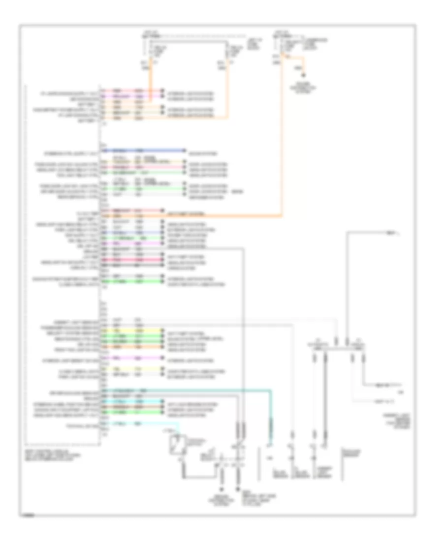
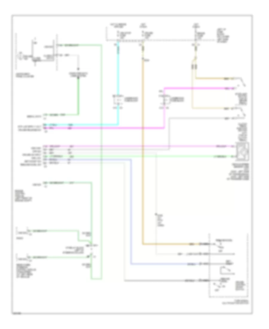
AIR CONDITIONING
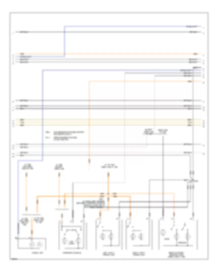
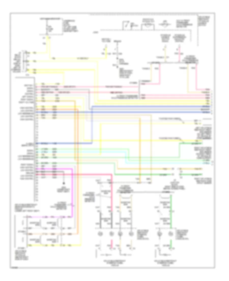
Automatic A/C Wiring Diagram (1 of 2) for GMC Cab & Chassis Sierra 2004 3500
 https://portal-diagnostov.com/license.html
Automotive Electricians Portal FZCO
Automotive Electricians Portal FZCO
https://portal-diagnostov.com/license.html
https://portal-diagnostov.com/license.html
Automotive Electricians Portal FZCO
Automotive Electricians Portal FZCO
List of elements for Automatic A/C Wiring Diagram (1 of 2) for GMC Cab & Chassis Sierra 2004 3500:
- (6.6l vin 1)
- (6.6l vin 2)
- (gasoline)
- 5v ref
- A/c comp cl rly ctrl
- A/c comp fuse 10a
- A/c compressor clutch
- A/c compressor clutch relay
- A/c low pressure switch (right side of accumulator)
- A/c on
- A/c recirc
- A/c ref pre sens sig
- A/c refrigerant pressure sensor (in high side pressure line)
- A10
- A11
- A12
- A5 c1
- Amb air temp sig
- Ambient air temperature sensor (in right front bumper filler assembly
- Auto
- B c5
- B(+)
- B10
- B11
- B12
- Blower fuse 40a
- Blower motor (right side of dash)
- Blower motor control processor (behind right side of dash)
- Blower speed ctrl
- C4 e
- C5 c1
- Class 2 ser data
- Class 2 serial data
- Fan dn
- Fan up
- Frt def
- G104 (on left rear of engine block)
- G200 (near right "a" pillar)
- G200 (near right side of dash, "a" pillar)
- G203 (near left "a" pillar)
- Ground
- Hot at all times
- Hot in run
- Hot in run or start
- Hvac 1 fuse 10a
- Hvac control module (behind center of dash)
- Hvac/ ecas fuse 10a
- I/p relay block (left side of dash)
- Ign 3
- Ign e fuse 10a
- Inside air temp sig
- Inside air temperature sensor assembly (in headliner above driver)
- Inst lamp dim ctrl
- Interior lights system
- Left i/p fuse block (lower left side of dash)
- Left temp control
- Lo lt air temp sig
- Lo press sens sig
- Lo rt air temp sig
- Logic
- Low ref
- Lower left air temperature sensor (left end of hvac module)
- Lower right air temperature sensor (bottom of hvac module)
- Lt temp door ctrl
- Mode
- Mode door ctrl
- Off
- Powertrain control module or engine control module (left front of engine compt)
- Recir
- Recir door ctrl
- Recirc door po sig
- Red
- Right i/p fuse block (lower right side of dash)
- Right temp control
- Rt temp door ctrl
- S102 (in engine harness)
- S218 (in i/p harn)
- S345
- Sp205 (in i/p harn)
- Speed ctrl
- Tan
- Temp sen ass ctrl
- Underhood fuse block (left side of engine compt, near battery)
- Up lt air temp sig
- Up rt air temp sig
- Upper left air temperature sensor (below dash trim panel)
- Upper right air temperature sensor (below dash trim panel)
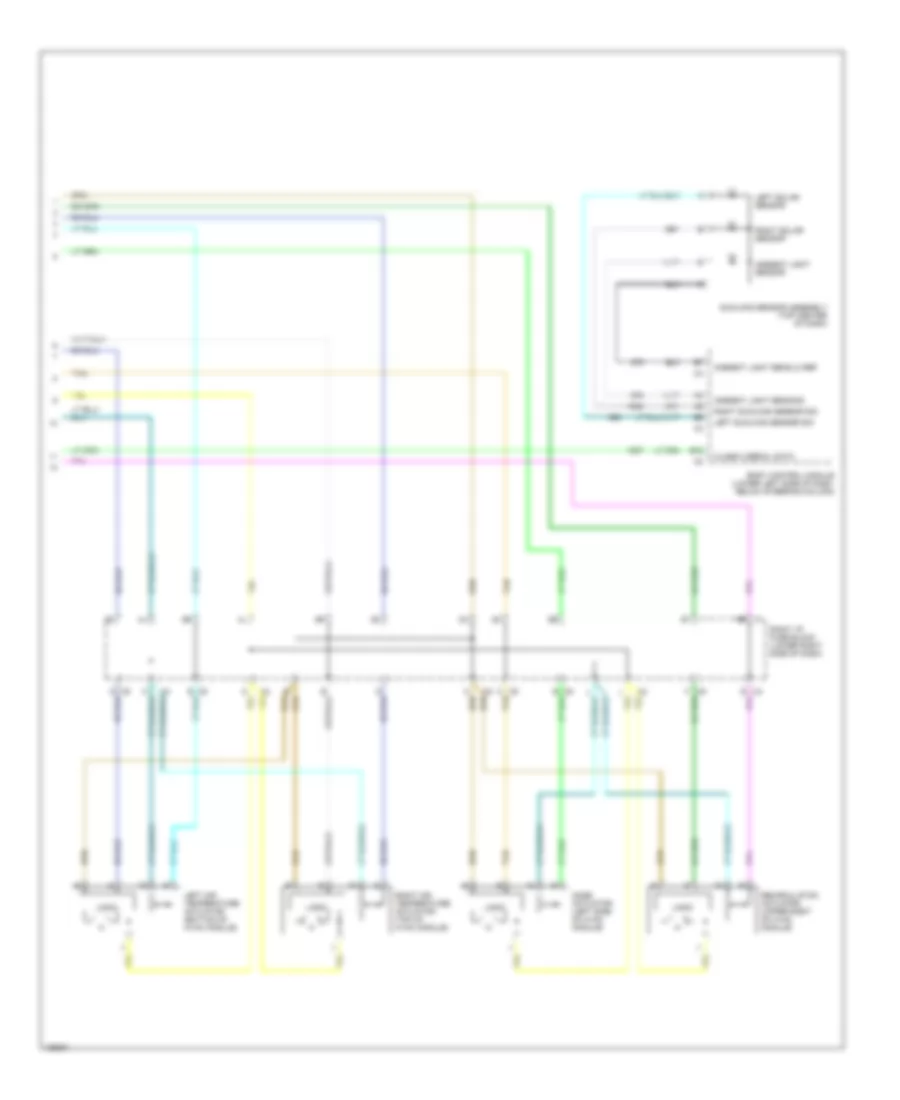
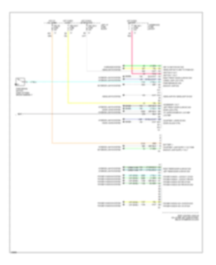
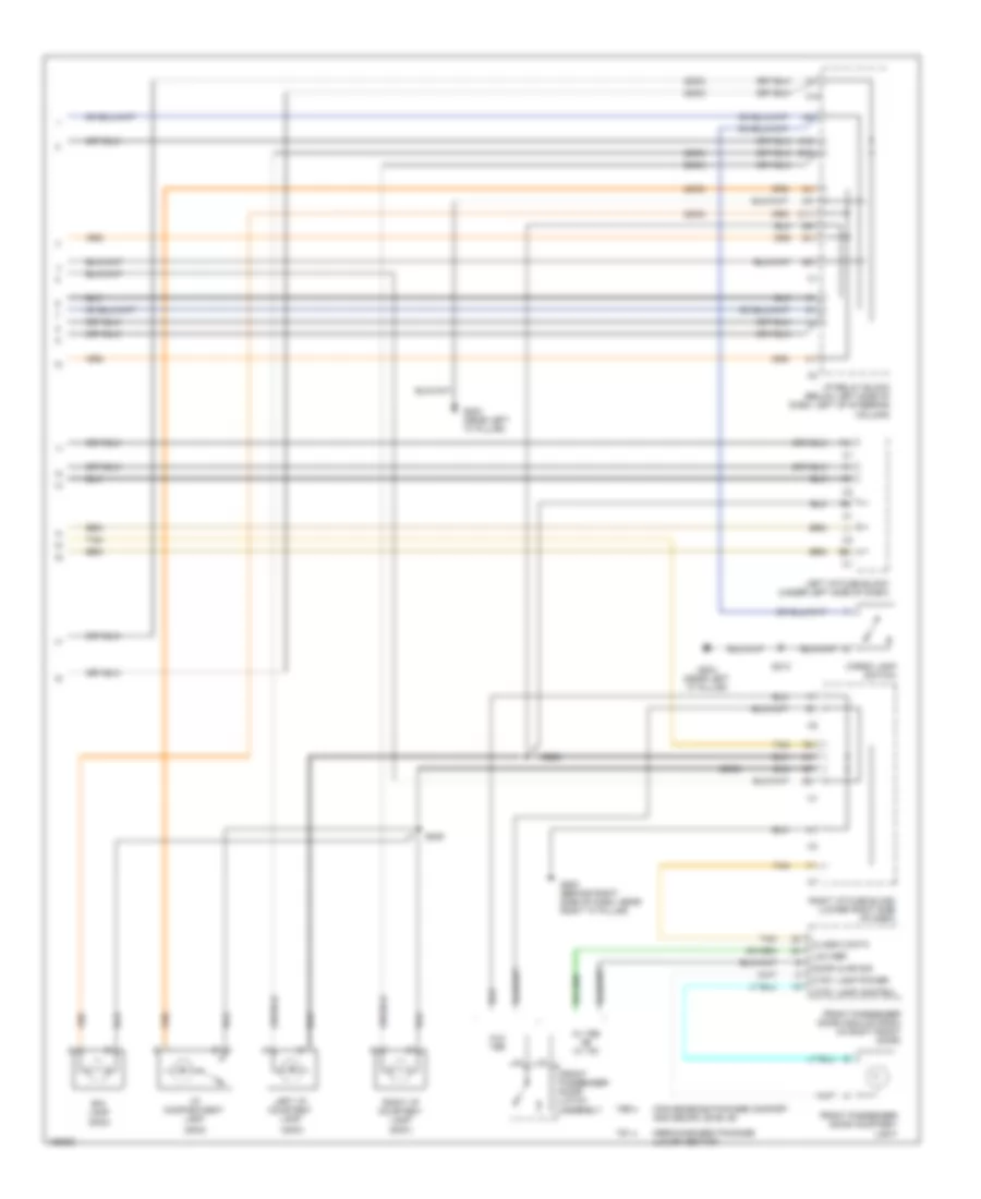
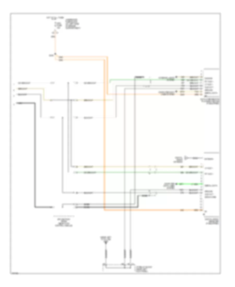
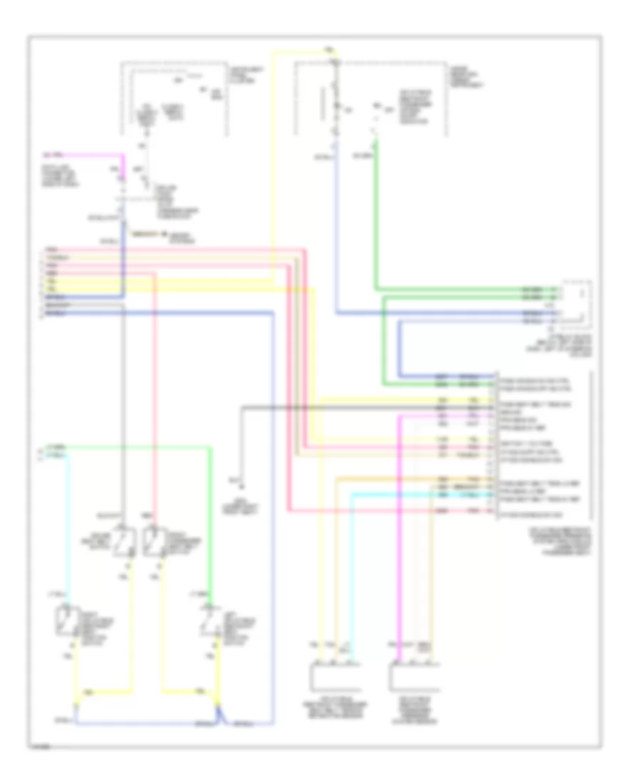
Automatic A/C Wiring Diagram (2 of 2) for GMC Cab & Chassis Sierra 2004 3500
List of elements for Automatic A/C Wiring Diagram (2 of 2) for GMC Cab & Chassis Sierra 2004 3500:
- Ambient light sens lo ref
- Ambient light sens sig
- Ambient light sensor
- B12
- Body control module (lower left side of dash, below steering column)
- Class 2 serial data
- Left air temperature actuator (bottom of hvac module)
- Left solar sensor
- Left sunload sensor sig
- Logic
- Mode actuator (left side of hvac module)
- Recirculation actuator (upper right of hvac module)
- Right air temperature actuator (top of hvac module)
- Right i/p fuse block (lower right side of dash)
- Right solar sensor
- Right sunload sensor sig
- Sunload sensor assembly (top center of dash)
- Tan
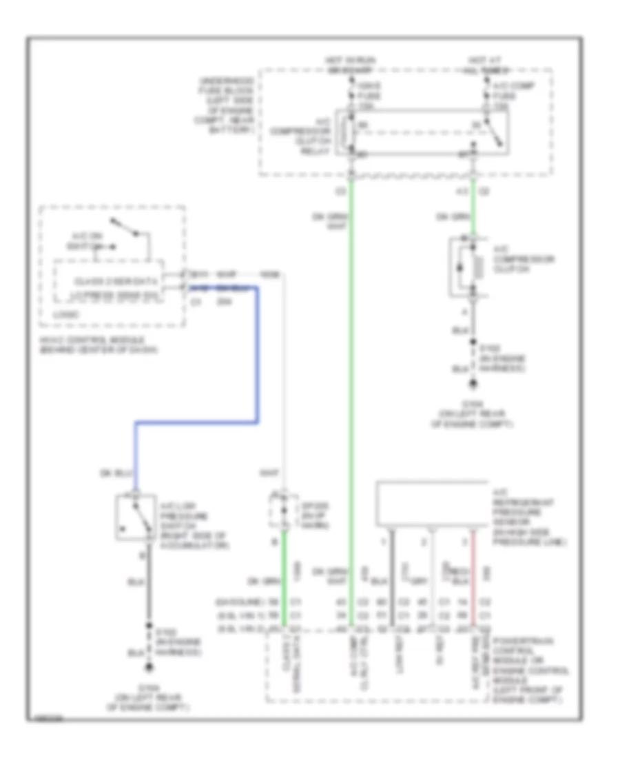
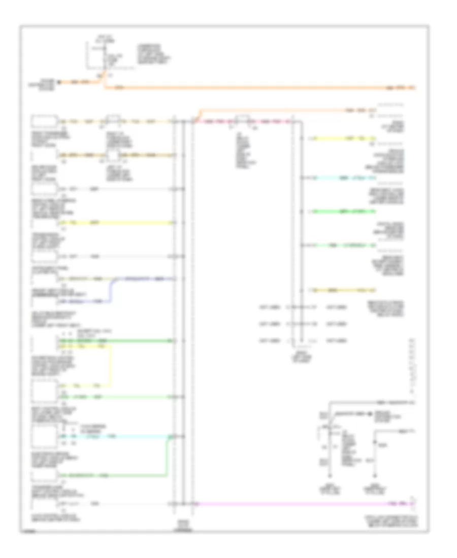
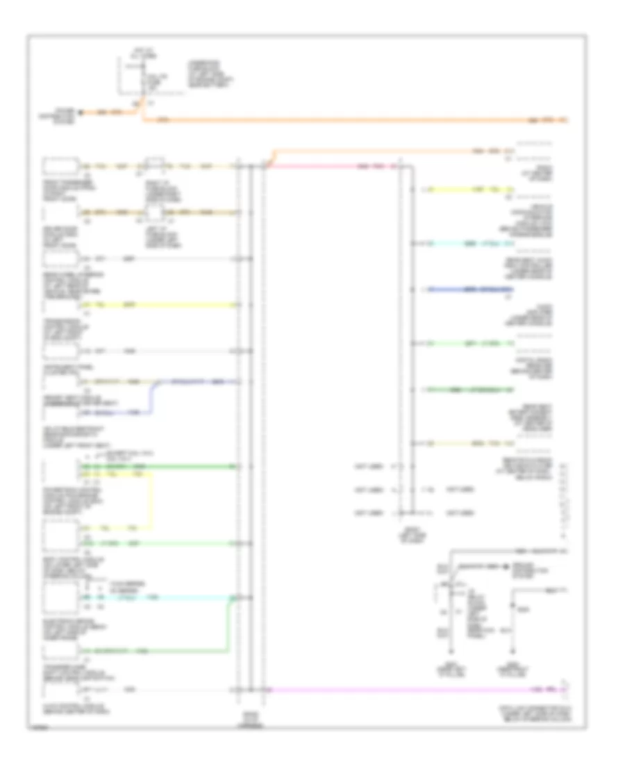
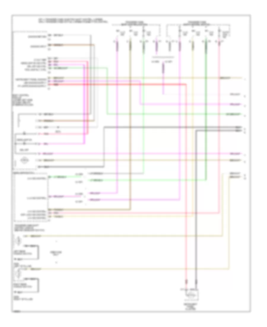
Compressor Wiring Diagram for GMC Cab & Chassis Sierra 2004 3500
List of elements for Compressor Wiring Diagram for GMC Cab & Chassis Sierra 2004 3500:
- (6.6l vin 1)
- (6.6l vin 2)
- (gasoline)
- 5v ref
- A/c comp cl rly ctrl
- A/c comp fuse 10a
- A/c compressor clutch
- A/c compressor clutch relay
- A/c low pressure switch (right side of accumulator)
- A/c on switch
- A/c ref pre sens sig
- A/c refrigerant pressure sensor (in high side pressure line)
- A12
- B11
- Class 2 ser data
- Class 2 serial data
- G104 (on left rear of engine compt)
- Hot at all times
- Hot in run or start
- Hvac control module (behind center of dash)
- Ign e fuse 10a
- Lo press sens sig
- Logic
- Low ref
- Powertrain control module or engine control module (left front of engine compt)
- Sp205 (in i/p harn)
- Underhood fuse block (left side of engine compt, near battery)
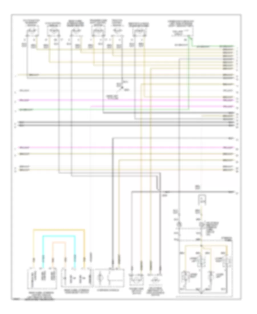
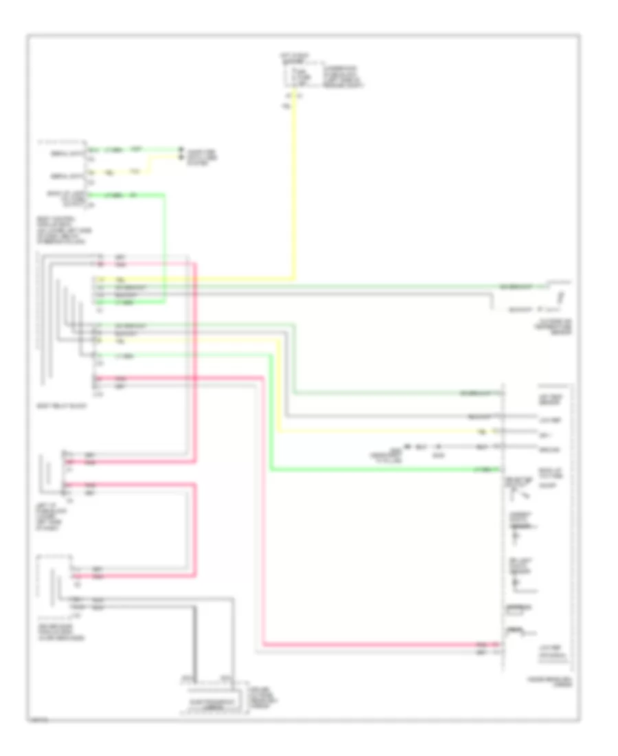
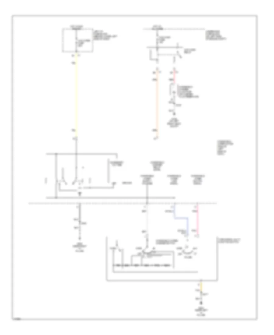
Heater Wiring Diagram for GMC Cab & Chassis Sierra 2004 3500
List of elements for Heater Wiring Diagram for GMC Cab & Chassis Sierra 2004 3500:
- 87a
- B c5
- Blower fuse 40a
- Blower motor (under right side of dash)
- Blower motor control switch
- Blower motor relay
- Blower motor resistor assembly (on hvac module, near blower motor)
- G200 (near right "a" pillar)
- Hot at all times
- Hot in run
- Htr a/c fuse 30a
- Hvac control module (behind center of dash)
- Left i/p fuse block (lower left side of dash)
- Off
- Red
- Right i/p fuse block (lower right side of dash)
- Tan
- Underhood fuse block (left side of engine compt, near battery)
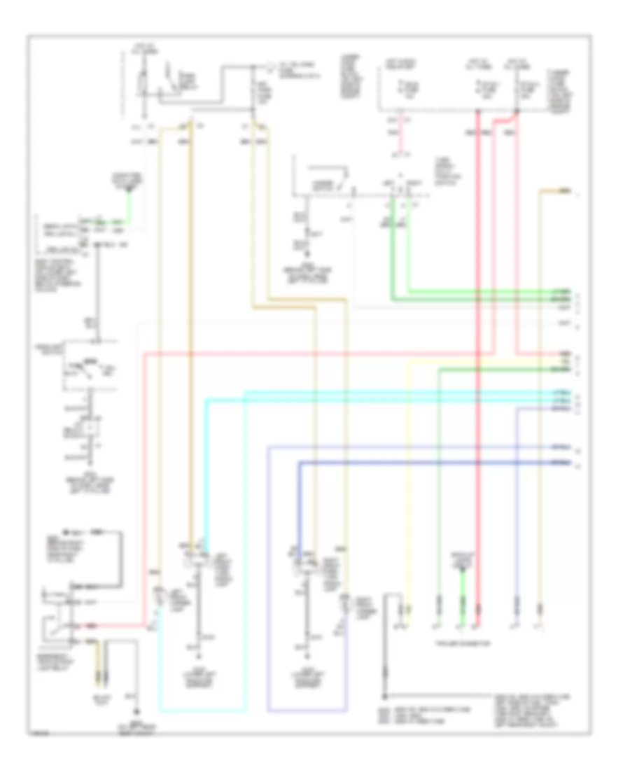
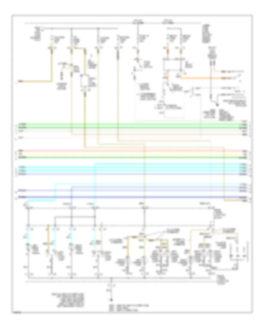
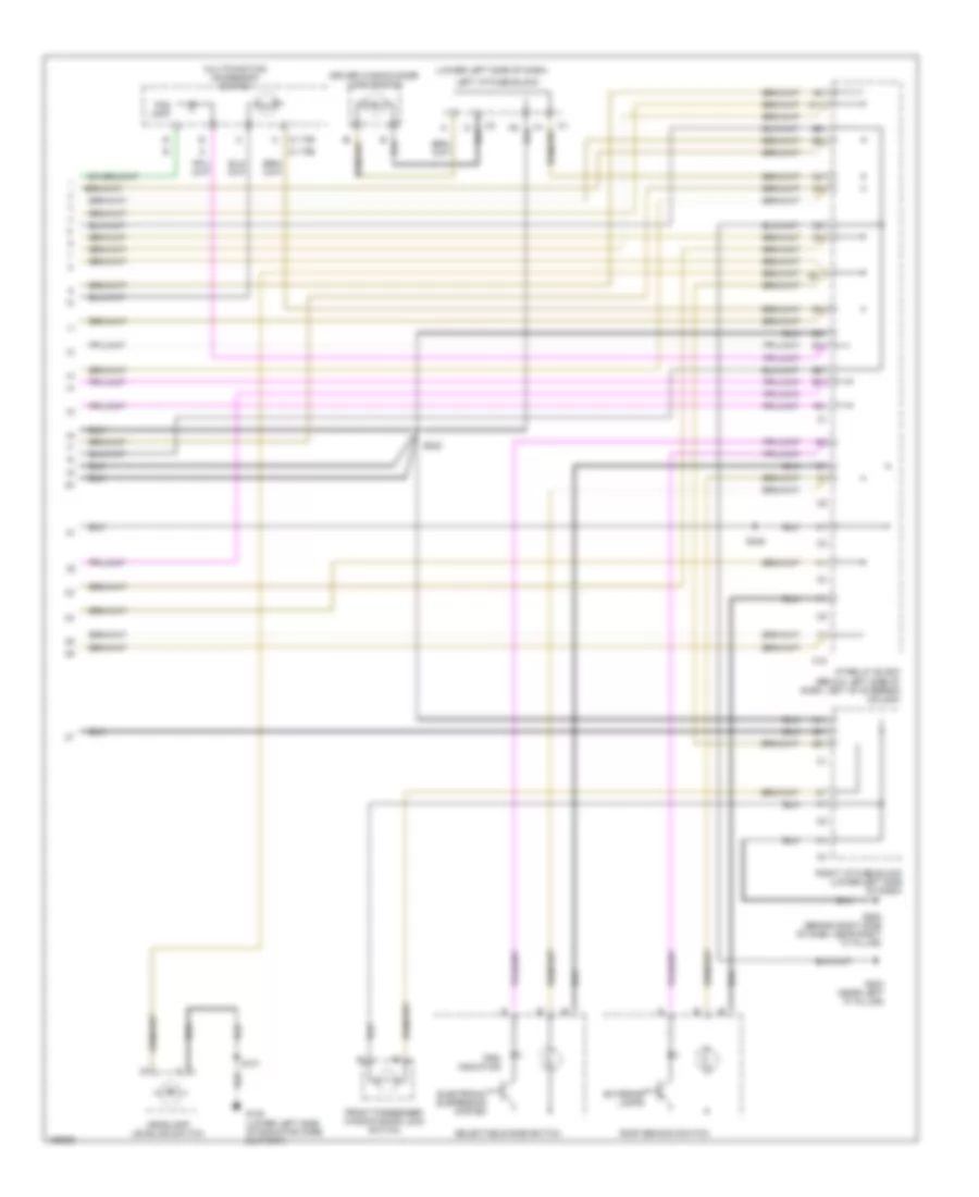
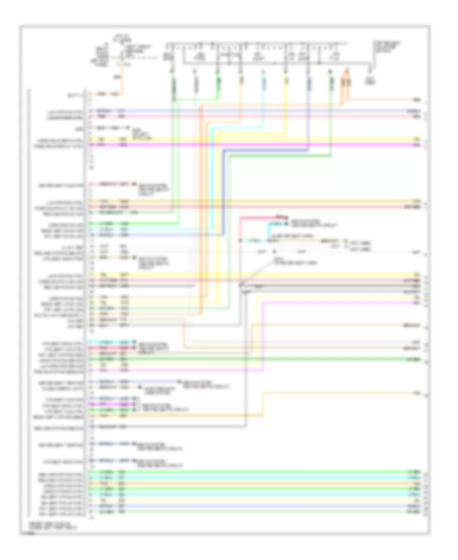
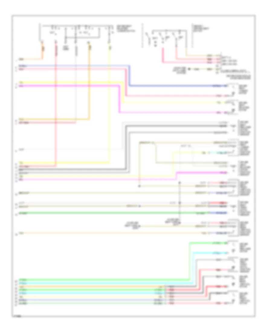
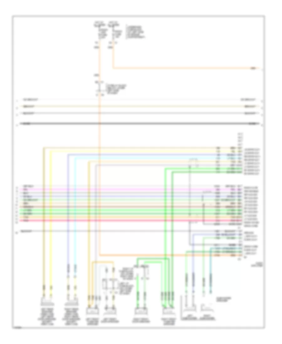
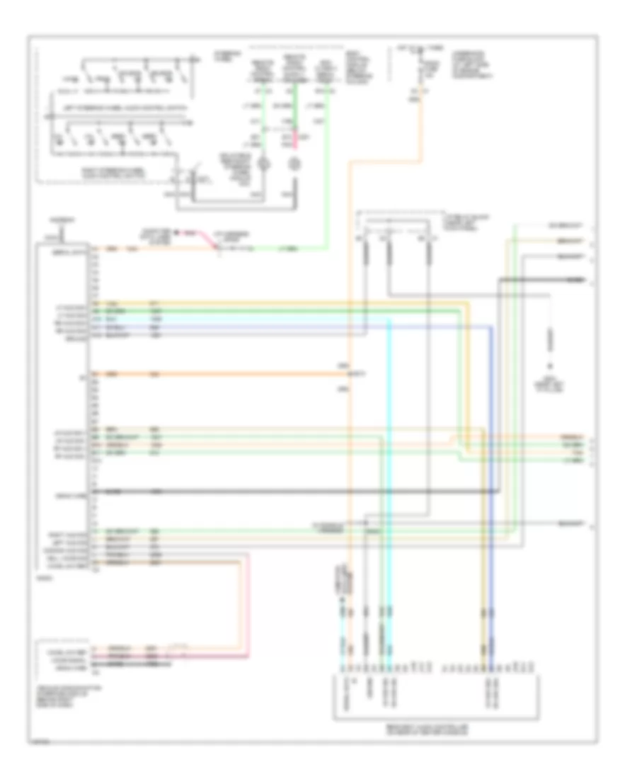
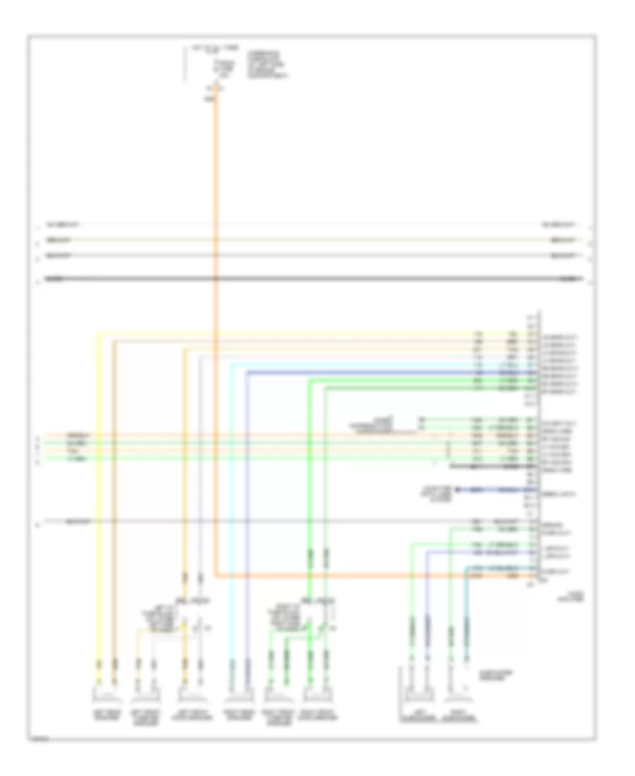
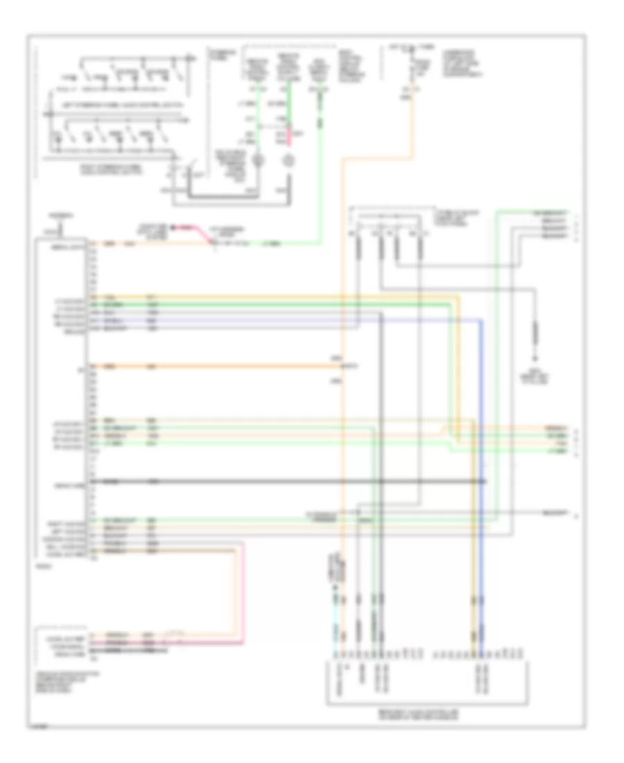
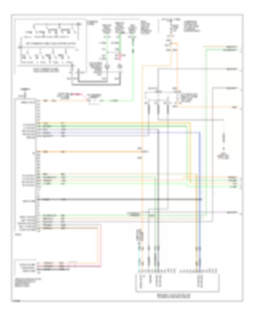
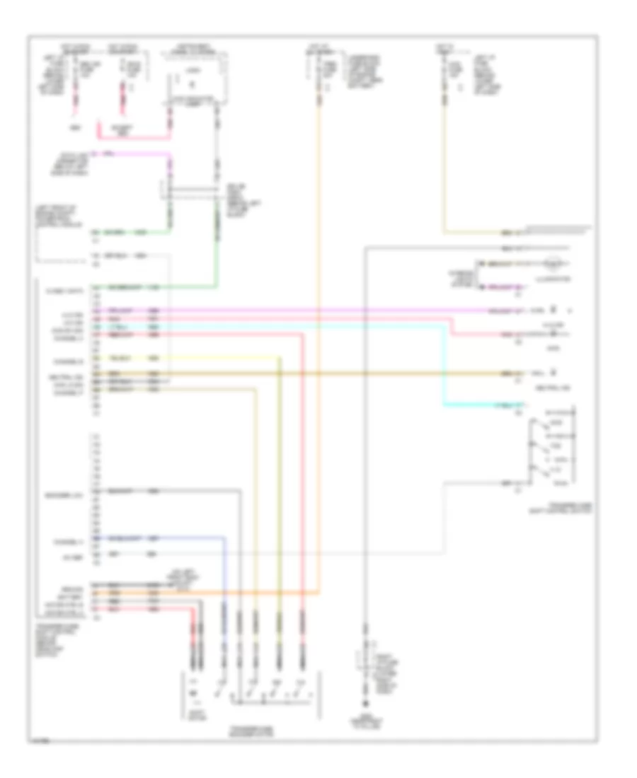
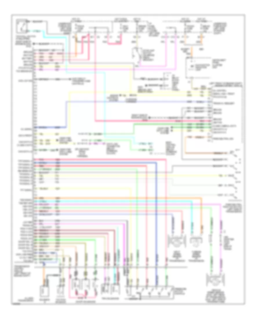
Manual A/C Wiring Diagram (1 of 2) for GMC Cab & Chassis Sierra 2004 3500
List of elements for Manual A/C Wiring Diagram (1 of 2) for GMC Cab & Chassis Sierra 2004 3500:
- (6.6l vin 1)
- (6.6l vin 2)
- (gasoline)
- 5v ref
- 87a
- A/c comp cl rly ctrl
- A/c comp fuse 10a
- A/c compressor clutch
- A/c compressor clutch relay
- A/c low pressure switch (right side of accumulator)
- A/c on switch
- A/c recirc
- A/c ref pre sens sig
- A/c refrigerant pressure sensor (in high side pressure line)
- A10
- A11
- A12
- A5 c1
- B c5
- B(+)
- B10
- B11
- B12
- Blower fuse 40a
- Blower motor (under right side of dash)
- Blower motor control switch
- Blower motor relay
- Blower motor resistor assembly (on hvac module, near blower motor)
- Class 2 ser data
- Class 2 serial data
- Frt def
- G104 (on left rear of engine block)
- G200 (near right "a" pillar)
- G203 (near left "a" pillar)
- Ground
- Hot at all times
- Hot in run
- Hot in run or start
- Htr a/c fuse 30a
- Hvac 1 fuse 10a
- Hvac control module (behind center of dash)
- Hvac/ ecas fuse 10a
- I/p relay block (left side of dash)
- Ign 3
- Ign e fuse 10a
- Inst lamp dim ctrl
- Interior lights system
- Left i/p fuse block (lower left side of dash)
- Left temp control
- Lo press sens sig
- Logic
- Low ref
- Lt temp door ctrl
- Mode control
- Mode door ctrl
- Off
- Off blow mt ctrl
- Powertrain control module or engine control module (left front of engine compt)
- Recir door ctrl
- Recirc switch
- Red
- Right i/p fuse block (lower right side of dash)
- Right temp control
- Rt temp door ctrl
- S102 (in engine harness)
- Sp205 (in i/p harn)
- Tan
- Underhood fuse block (left side of engine compt, near battery)
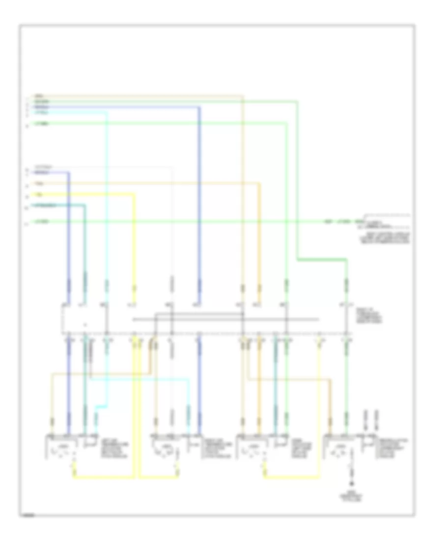
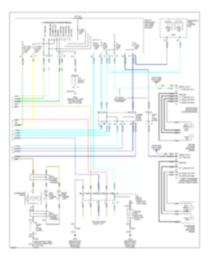
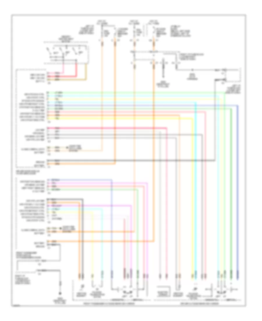
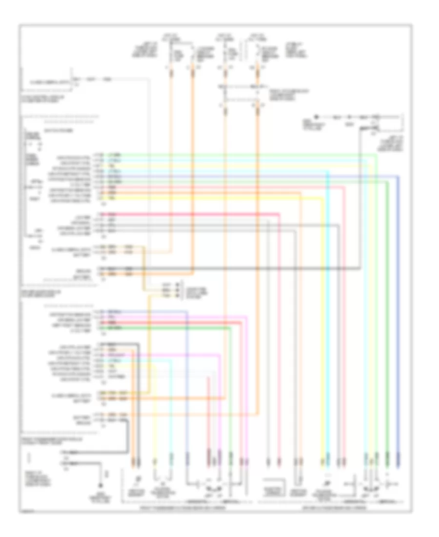
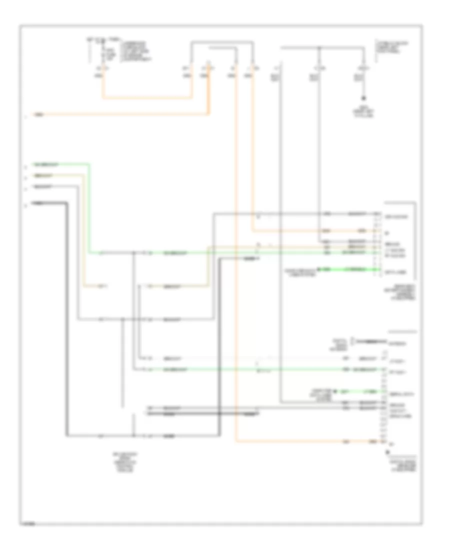
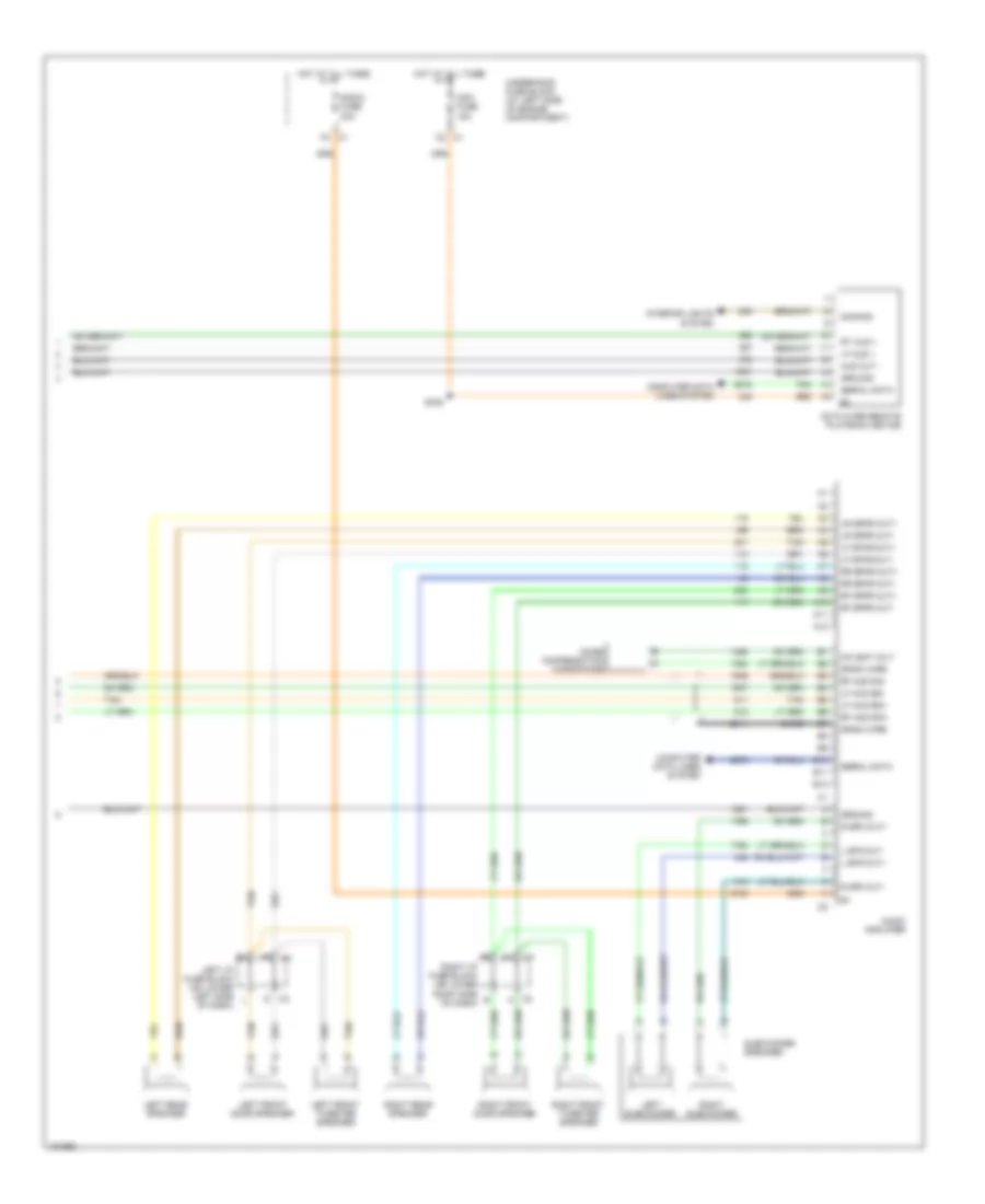
Manual A/C Wiring Diagram (2 of 2) for GMC Cab & Chassis Sierra 2004 3500
List of elements for Manual A/C Wiring Diagram (2 of 2) for GMC Cab & Chassis Sierra 2004 3500:
- (not used)
- B12
- Body control module (lower left side of dash, below steering column)
- Class 2 serial data
- G200 (near right "a" pillar)
- Left air temperature actuator (bottom of hvac module)
- Logic
- Mode actuator (left side of hvac module)
- Recirculation actuator (upper right of hvac module)
- Right air temperature actuator (top of hvac module)
- Right i/p fuse block (lower right side of dash)
- Tan
ANTI-LOCK BRAKES
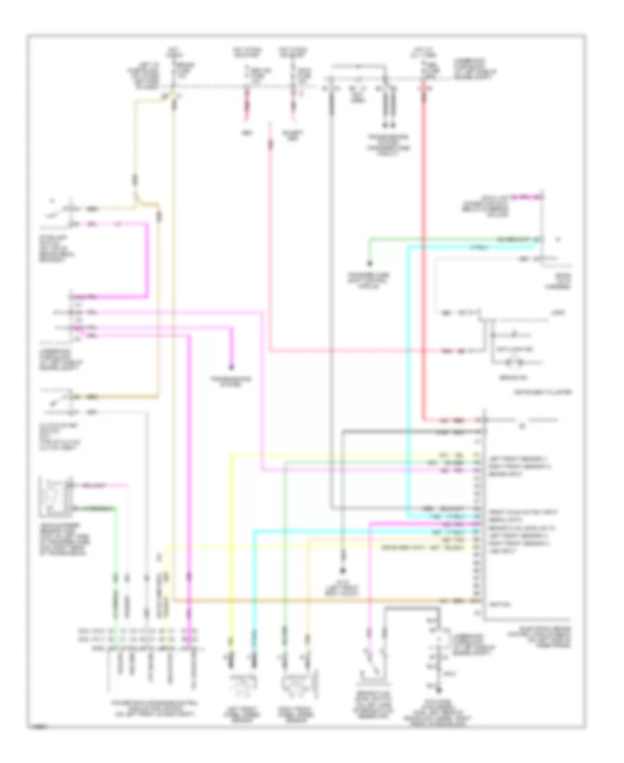
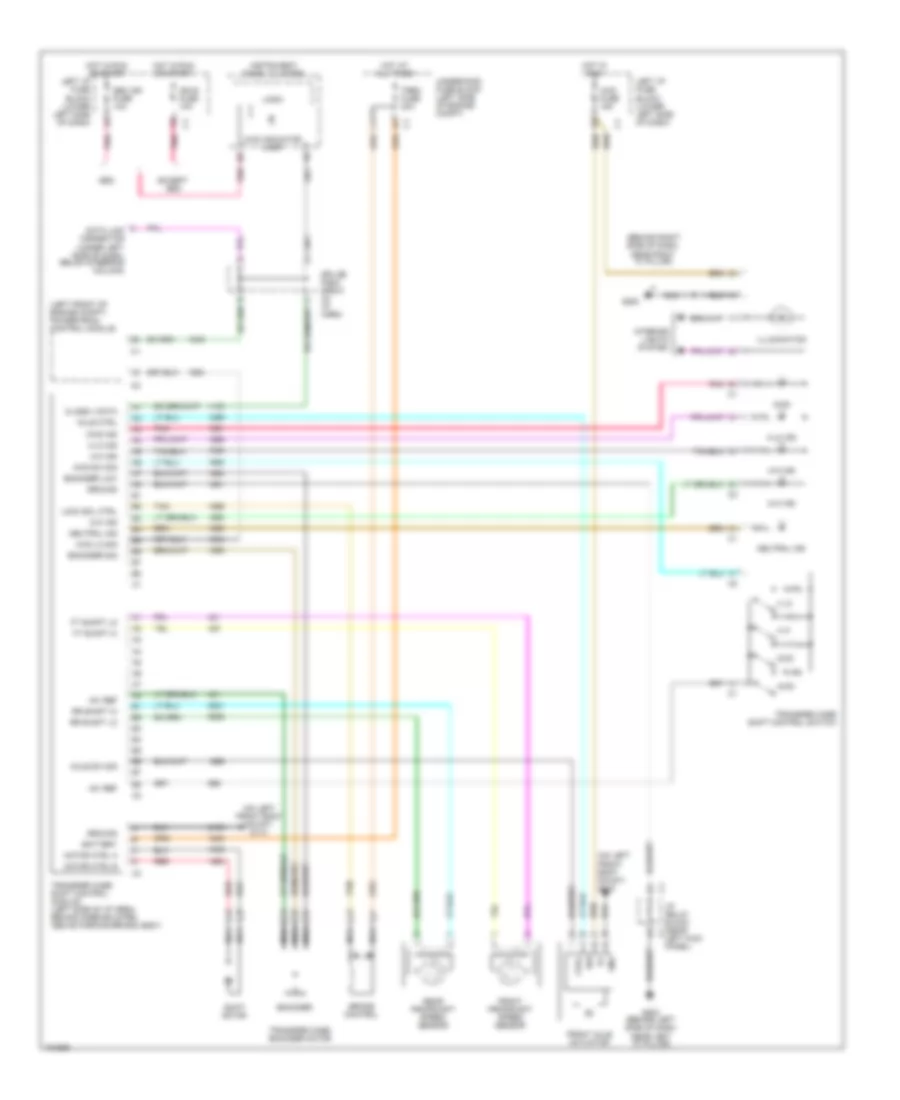
Anti-lock Brakes Wiring Diagram for GMC Cab & Chassis Sierra 2004 3500
List of elements for Anti-lock Brakes Wiring Diagram for GMC Cab & Chassis Sierra 2004 3500:
- (6.6l vin 1)
- (6.6l vin 2)
- (gas)
- (not used)
- A10
- Abs fuse 60a
- Anti-lock ind
- B1 c3
- B10
- Brake fluid level sw in
- Brake fluid level switch (on left side of brake fluid reservoir)
- Brake fuse 10a
- Brake ind
- Brake input
- C12
- C2 b7
- C9 a
- Clutch start switch (m/t) (top of clutch clutch assy)
- Cpp sw sig
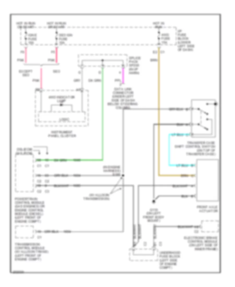
- Data link connector (dlc) (below steering column)
- E6 c1
- Electronic brake control module (ebcm) (on left side of inner frame)
- Except seo
- Front axle act/sw input
- G104 (gas) g106 (diesel) (gas: left rear of eng block, diesel: right front of eng block)
- G110 (left front body mount)
- Hot at all times
- Hot in run
- Hot in run or start
- Ign e fuse 10a
- Ignition
- Instrument cluster
- Left front sensor (+)
- Left front sensor (-)
- Left front wheel speed sensor
- Left i/p fuse block (on lower left side of dash)
- Logic
- Nca
- Pnk
- Powertrain or engine control module (pcm or ecm) (on left front of eng compt)
- Red
- Right front sensor (+)
- Right front sensor (-)
- Right front wheel speed sensor
- S102
- Seo
- Seo ign fuse 10a
- Serial data
- Sp205 (in i/p harness)
- Stoplamp switch (on top of brake pedal bracket)
- Tan
- Tcc brake sw
- Transfer case shift control module
- Transmissions system
- Transmissions system (transfer case circuit)
- Underhood fuse block (at left side of engine compt)
- Vehicle speed sensor (vss) (4wd: on left side of transfer case, 2wd: right rear of transmission)
- Vss high
- Vss input
- Vss low
- Vss output
ANTI-THEFT
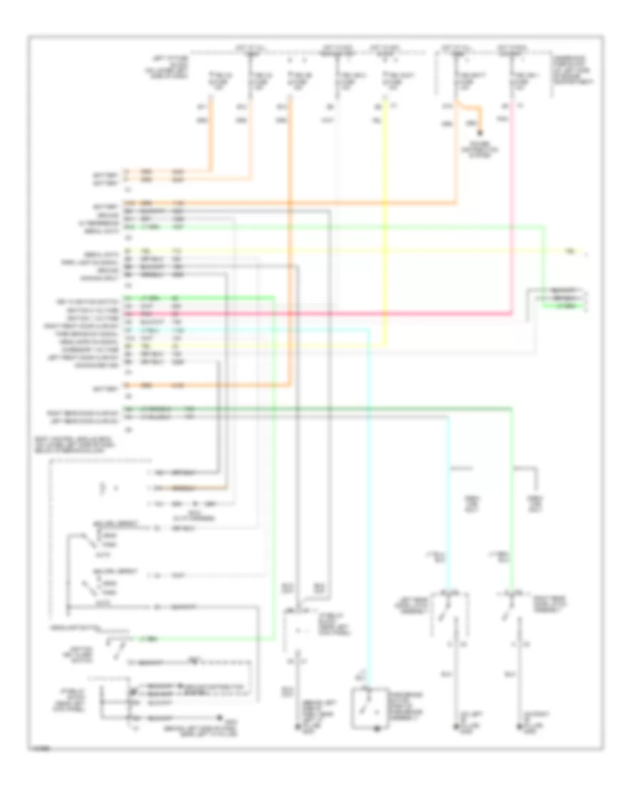
Forced Entry Wiring Diagram for GMC Cab & Chassis Sierra 2004 3500
List of elements for Forced Entry Wiring Diagram for GMC Cab & Chassis Sierra 2004 3500:
- (inside driver door)
- (inside right front passenger door)
- (lower left side of dash, near steering column)
- A12
- Ajar sw
- All times
- B12
- Base
- Battery
- Body control module
- D12
- Door ajar sw sig
- Door sw lo ref
- Driver door module
- Driver mini-wedge door jamb switch (rear of driver's door)
- Exterior lights system
- Front passenger door module
- Front passenger mini-wedge door jamb switch (rear of right front door)
- G200 (behind right side of dash)
- G203 (near left "a" pillar)
- G305 (bottom of left "b" pillar)
- G306 (bottom of right "b" pillar)
- Ground
- Headlights ctrl
- Headlights system
- Horn rly ctrl
- Horns system
- Hot at
- I/p relay block (near left kick panel)
- Key sw
- Key sw lo ref
- Key sw sig
- Left i/p fuse block (lower left side of dash)
- Left rear mini-wedge door jamb switch (crew cab) (rear or left rear door)
- Lf door ajar sw
- Lr door ajar sw
- Pk lamp rel
- Rf door ajar sw
- Right i/p fuse block (lower right side of dash)
- Right rear mini-wedge door jamb switch (crew cab) (rear or right rear door)
- Rr door ajar sw
- Serial data
- Splice pack sp205 (in i/p harness)
- Tan
- Tbc batt fuse 10a
- Underhood fuse block (left side of eng compt)
- Uplevel
Passlock Wiring Diagram for GMC Cab & Chassis Sierra 2004 3500
List of elements for Passlock Wiring Diagram for GMC Cab & Chassis Sierra 2004 3500:
- 12v reference
- A11
- A12
- B12
- Battery
- Body control module (lower left side of dash, near steering column)
- Class 2 serial data
- D12
- Data
- Data link connector (under left side of dash)
- Except 6.6l vin 2 6.6l vin 2
- G203 (near left "a" pillar)
- Ground
- Hot at all times
- Hot in run & start
- I/p relay block (near left kick panel)
- Ign
- Ign 1 voltage
- Ign sw sig
- Ignition key alarm switch (on ignition key cylinder)
- Instrument panel cluster
- Key
- Lock cylinder
- Low reference
- Magnet
- Passlock sensor (internal to steering column)
- Pnk
- Powertrain control module (pcm) or engine conrtrol module (ecm) (on left front of engine compt)
- S217 (in steering column harness)
- Sec sens sig
- Security indicator
- Security sensor
- Serial data
- Splice pack sp205 (in i/p harn)
- Tamper sensor
- Tbc batt fuse 10a
- Tbc ign 1 fuse 10a
- Underhood fuse block (left side of eng compt)
BODY CONTROL MODULES
Body Control Modules Wiring Diagram (1 of 2) for GMC Cab & Chassis Sierra 2004 3500
List of elements for Body Control Modules Wiring Diagram (1 of 2) for GMC Cab & Chassis Sierra 2004 3500:
- (base) (upper level)
- (bsae)
- (upper level)
- 12 volt ref
- A10
- A11
- A12
- Ambient light sens sig
- Ambient light sensor
- Ambient light sensor (top center of dash)
- Anti-lock brakes system
- Anti-theft system
- B10
- B11
- B12
- Battery +
- Body control module (on lower left side of dash, below steering column)
- Class 2 serial data
- Computer data lines system
- D12
- Defogger system
- Dimming input/courtesy lmp pwm
- Dimming potentiometer 5volt ref
- Door locks system
- Driver door unlock rly ctrl
- Driver sunload sens sig
- Drl off ind
- Drl relay ctrl
- Drl sw sig
- E11
- E12
- Exterior lights system
- Fog light relay ctrl
- Front fog lamp sw sig
- G203 (behind left side of dash, near "a" pillar)
- Ground
- Ground distribution system
- Headlamp high beam relay ctrl
- Headlamp low beam relay ctrl
- Headlights system
- Horn rly ctrl
- Horns system
- Hot at all times
- I/p lamp dinning ctrl
- I/p relay block
- Interior lamp defeat sw sig
- Interior lights system
- L solar sensor
- Led dimming sig
- Left i/p fuse block
- Low ref
- Park lamp relay ctrl
- Park lamp sw on sig
- Pass door lock sw lock ctrl
- Pass door lock sw unlock ctrl
- Passenger sunload sens sig
- Pnk
- Power distribution system
- Power tops system
- R solar sensor
- Rear defog rly ctrl
- Red
- Remote radio ctrl sig
- Security system sens sig
- Sound system
- Steering wheel position sen sig
- Sunload sensor
- Tbc 2a fuse 15a
- Tbc 2c fuse 15a
- Tbc batt fuse 10a
- Tow/haul sw sig
- Tow/haul switch
- Underhood fuse block
- W/ automatic a/c
- W/ manual a/c
Body Control Modules Wiring Diagram (2 of 2) for GMC Cab & Chassis Sierra 2004 3500
List of elements for Body Control Modules Wiring Diagram (2 of 2) for GMC Cab & Chassis Sierra 2004 3500:
- (base)
- (crew cab)
- (up level)
- A10
- A11
- Accessory volt
- B11
- B12
- Backup lamp sig
- Battery +
- Body control module (on lower left side of dash, below steering column)
- Cargo lamp low ctrl
- Courtesy lamps on sig
- Door lock ctrl
- Door locks system
- Door unlock ctrl
- Exterior lights system
- Headlamp sw flash to pass sig
- Headlamp sw headlamp on sig
- Headlights system
- Hot at all times
- Hot in run & acc
- Hot in run & start
- Hot in run, start & acc
- I/p lamps dimmer sw low ref
- Ignition 0 volt
- Ignition 1 volt
- Interior lights system
- Key in ignition sw sig
- Left front door ajar sw sig
- Left i/p fuse block
- Left rear door ajar sw sig
- Low ref
- Park brake sw sig
- Park brake switch (part of park brake assembly)
- Pnk
- Power window lockout lr sig
- Power window lockout rr sig
- Power window sw lr down sig
- Power window sw lr up sig
- Power window sw rr down sig
- Power window sw rr up sig
- Power windows system
- Right front door ajar sw sig
- Right rear door ajar sw sig
- Tbc 2b fuse 15a
- Tbc accy fuse 10a
- Tbc ign 0 fuse 10a
- Tbc ign 1 fuse 10a
- Underhood fuse block
- Warnings system
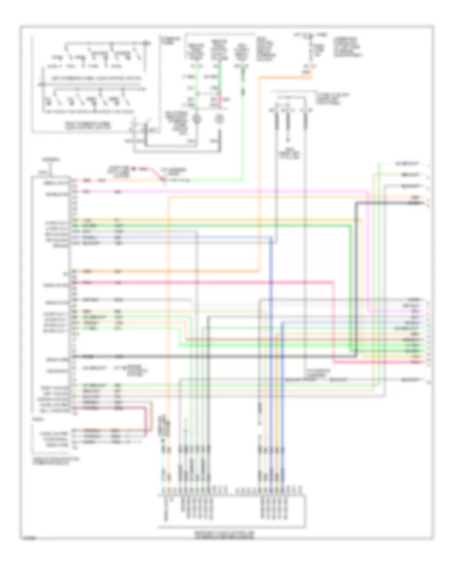
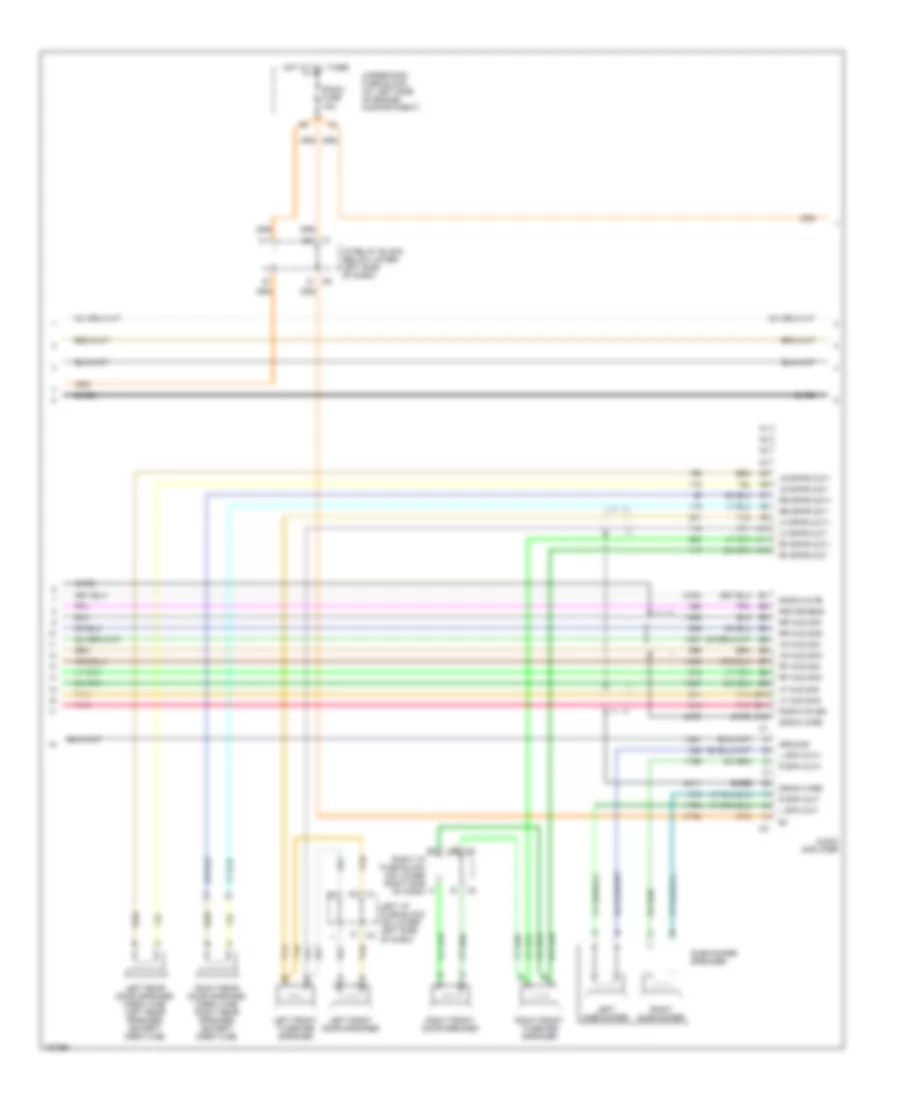
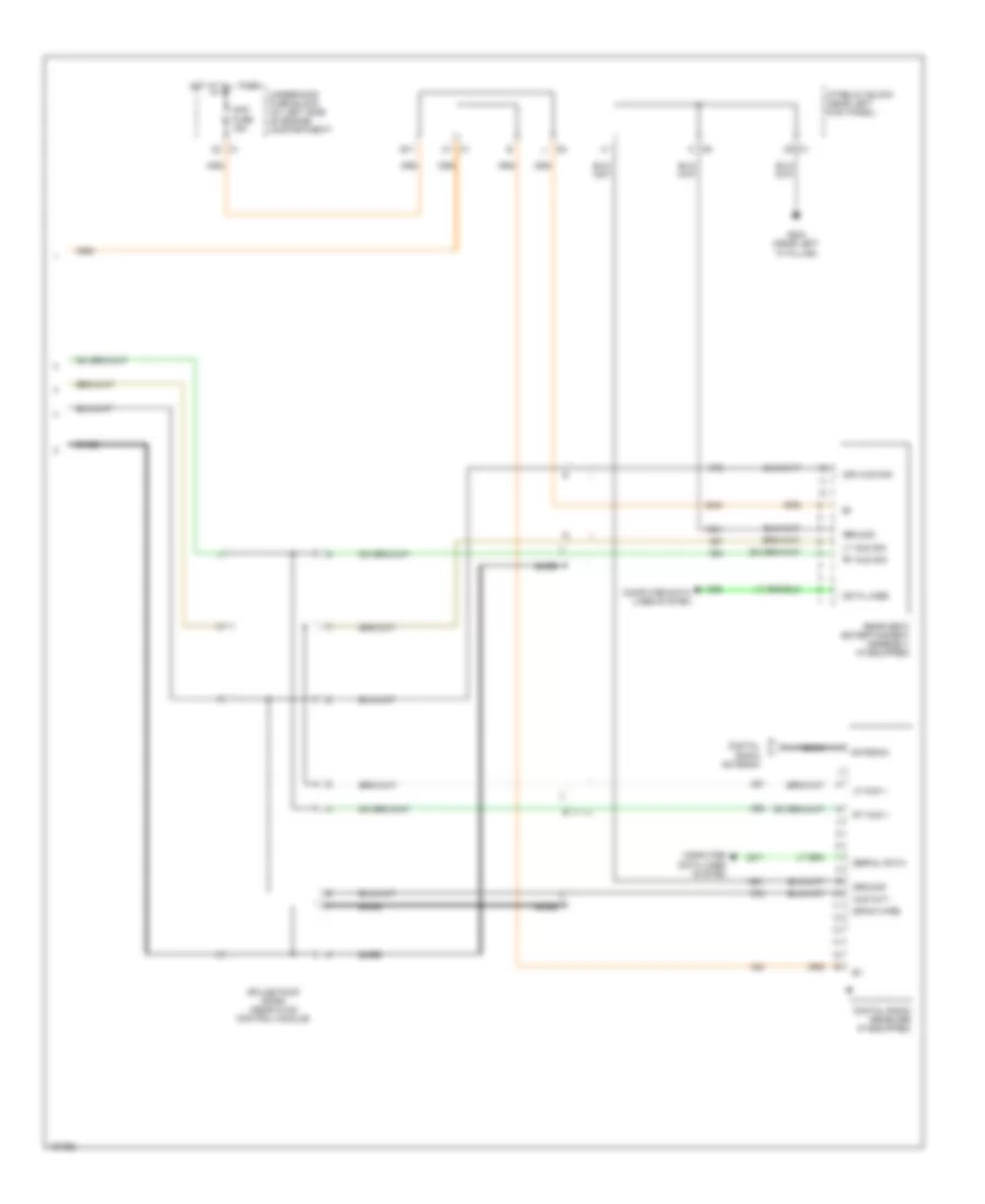
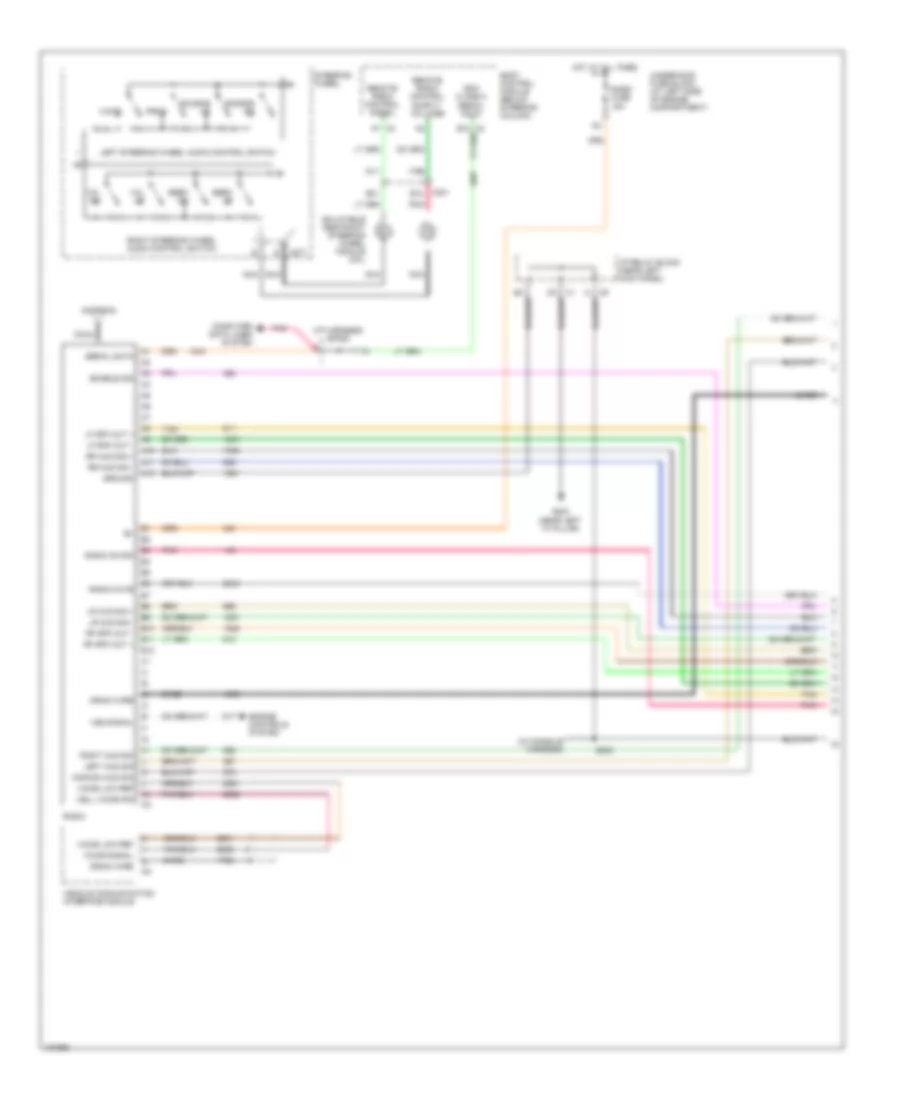
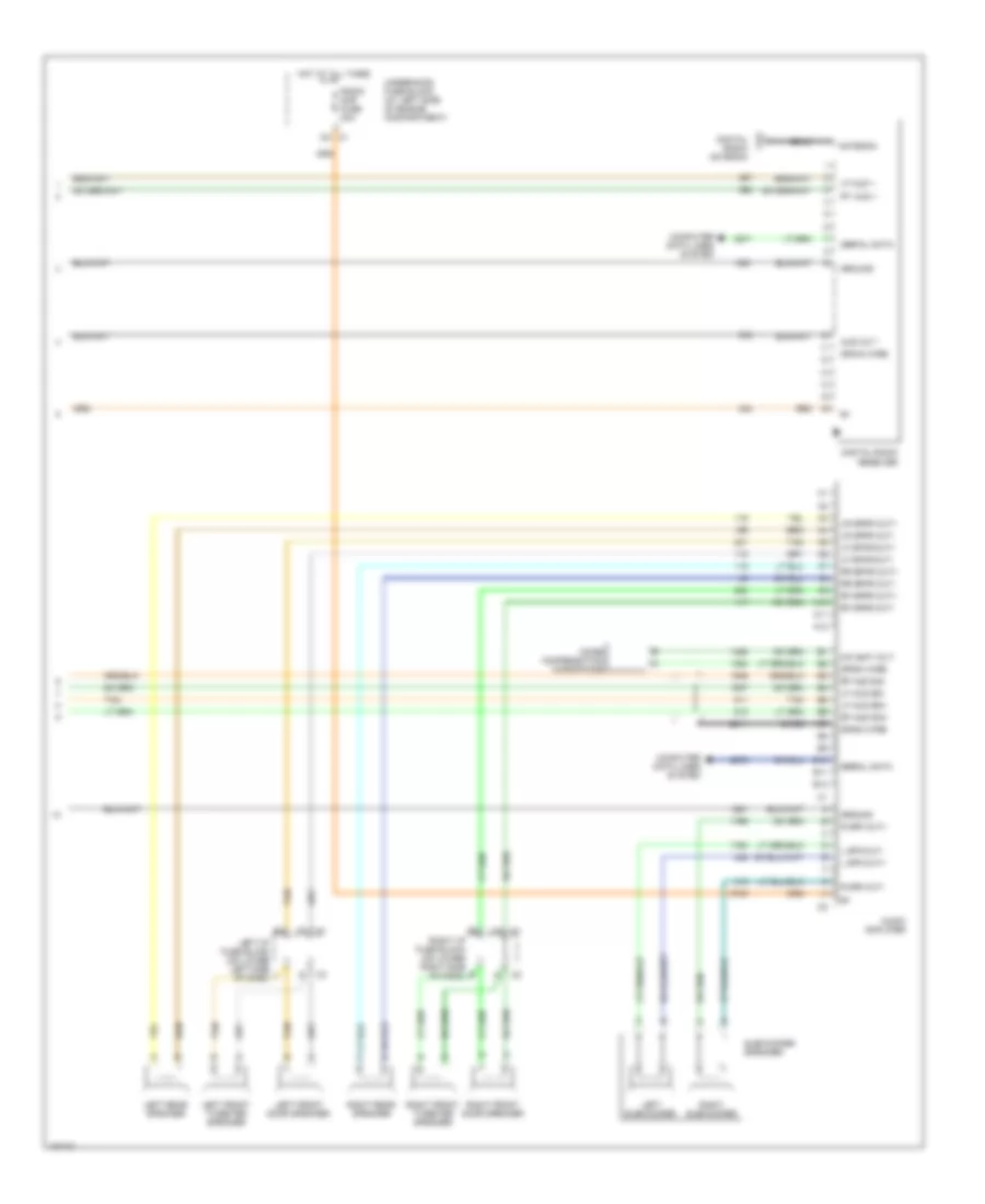
COMPUTER DATA LINES
Computer Data Lines Wiring Diagram, Base & Up-Level for GMC Cab & Chassis Sierra 2004 3500
List of elements for Computer Data Lines Wiring Diagram, Base & Up-Level for GMC Cab & Chassis Sierra 2004 3500:
- (10/20 series)
- (30 series)
- (not used)
- B11
- B12
- Body control module (on lower left side of dash, below steering column)
- Cig ltr fuse 15a
- Data link connector (dlc) (under left side of dash, below steering column)
- Digital radio receiver (behind center of dash)
- Driver door module (ddm) (in left front door)
- Electronic brake control module (ebcm) (on left side of inner frame)
- Except 6.6l vin 2 6.6l vin 2
- Front passenger door module (fpdm) (in right front door)
- G200 (near right "a" pillar)
- G203 (near left "a" pillar)
- Ground distribution system
- Hot at all times
- Hvac control module (behind center of dash)
- I/p relay block (under left side of dash, near kick panel)
- Inflatable restraint sensing/diagnostic module (under left front seat)
- Instrument panel cluster (ipc)
- Left i/p fuse block (under left side of dash)
- Memory seat module (underside of driver seat)
- Pnk
- Power distribution system
- Powertrain control module (pcm)/engine control module (ecm) (on left front of engine compt)
- Radio (at center of dash)
- Rear seat audio (rsa) controller (under rear of center console)
- Rear seat entertainment (rse) assembly (at center of headliner)
- Rear wheel steering control module (at left rear of vehicle, near spare tire bracket)
- Remote playback device-cd player (center of dash, below radio)
- Right i/p fuse block (under right side of dash)
- S202
- Sp205 (in i/p harness)
- Sp207 (left side of dash)
- Tan
- Transfer case shift control module (behind headlamp switch)
- Transmission control module (at left front of eng compt)
- Underhood fuse block (at left side of engine compt, near battery)
- Vehicle communication interface module (vcim) (behind passenger air bag module)
Computer Data Lines Wiring Diagram, Luxury for GMC Cab & Chassis Sierra 2004 3500
List of elements for Computer Data Lines Wiring Diagram, Luxury for GMC Cab & Chassis Sierra 2004 3500:
- (10/20 series)
- (30 series)
- (not used)
- Audio amplifier (under rear of center console)
- B10
- B11
- B12
- Body control module (on lower left side of dash, below steering column)
- Cig ltr fuse 15a
- Data link connector (dlc) (under left side of dash, below steering column)
- Digital radio receiver (behind center of dash)
- Driver door module (ddm) (in left front door)
- Electronic brake control module (ebcm) (on left side of inner frame)
- Except 6.6l vin 2 6.6l vin 2
- Front passenger door module (fpdm) (in right front door)
- G200 (near right "a" pillar)
- G203 (near left "a" pillar)
- Ground distribution system
- Hot at all times
- Hvac control module (behind center of dash)
- I/p relay block (under left side of dash, near kick panel)
- Inflatable restraint sensing/diagnostic module (under left front seat)
- Instrument panel cluster (ipc)
- Left i/p fuse block (under left side of dash)
- Memory seat module (underside of driver seat)
- Pnk
- Power distribution system
- Powertrain control module (pcm)/engine control module (ecm) (on left front of engine compt)
- Radio (at center of dash)
- Rear seat audio (rsa) controller (under rear of center console)
- Rear seat entertainment (rse) assembly (at center of headliner)
- Rear wheel steering control module (at left rear of vehicle, near spare tire bracket)
- Remote playback device-cd player (at center of dash, below radio)
- Right i/p fuse block (under right side of dash)
- S202
- Sp205 (in i/p harness)
- Sp207 (left side of dash)
- Tan
- Transfer case shift control module (behind headlamp switch)
- Transmission control module (at left front of eng compt)
- Underhood fuse block (at left side of engine compt, near battery)
- Vehicle communication interface module (vcim) (behind passenger air bag module)
CRUISE CONTROL
6.6L VIN 2
6.6L VIN 2, Cruise Control Wiring Diagram for GMC Cab & Chassis Sierra 2004 3500
List of elements for 6.6L VIN 2, Cruise Control Wiring Diagram for GMC Cab & Chassis Sierra 2004 3500:
- A10
- Brake fuse 10a
- C12
- Class 2 data
- Clutch pedal position switch (m/t) (top of clutch pedal)
- Computer data lines system
- Cpp sw
- Cruise control on/off switch
- Cruise fuse 10a
- Cruise ind
- Cruise on input
- Cruise release sw
- Engine control module (left front of engine compt)
- Hot in run
- I/p relay block (left of steering column)
- Ign
- Instrument panel cluster
- Left i/p fuse block (on lower left side of dash)
- Nca
- Off
- Radio
- Rear wheel steering control module (if equipped) (at left rear of vehicle)
- Resume/ accel
- Resume/accel
- Resume/accel sw
- S162 (w/ pto) (i/p harn)
- S240
- Serial data
- Set/ coast
- Set/coast sw
- Stoplamp switch (top of brake pedal)
- Turn signal multifunction switch
- Underhood fuse block
- Veh stop fuse 15a
- Vehicle speed sensor (vss) (m/t) (2wd: left side of transmission) (4wd: left side of transfer case)
- Vss high
- Vss low
- Vss sig
DEFOGGERS
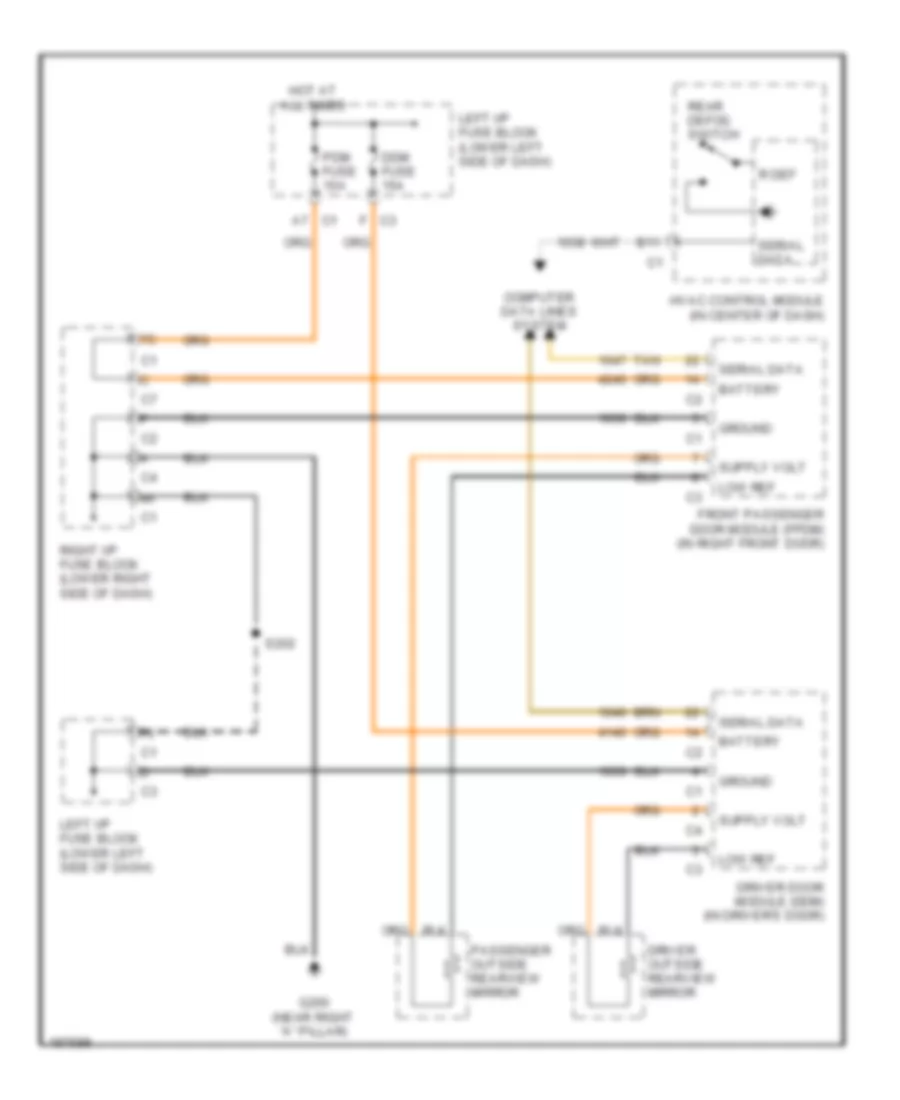
Heated Mirrors Wiring Diagram for GMC Cab & Chassis Sierra 2004 3500
List of elements for Heated Mirrors Wiring Diagram for GMC Cab & Chassis Sierra 2004 3500:
- A7 c1
- B11
- Battery
- Computer data lines system
- Ddm fuse 15a
- Driver door module (ddm) (in driver's door)
- Driver outside rearview mirror
- F c3
- Front passenger door module (fpdm) (in right front door)
- G200 (near right "a" pillar)
- Ground
- Hot at all times
- Hvac control module (in center of dash)
- Left i/p fuse block (lower left side of dash)
- Low ref
- Passenger outside rearview mirror
- Pdm fuse 10a
- R def
- Rear defog switch
- Right i/p fuse block (lower right side of dash)
- S202
- Serial data
- Tan
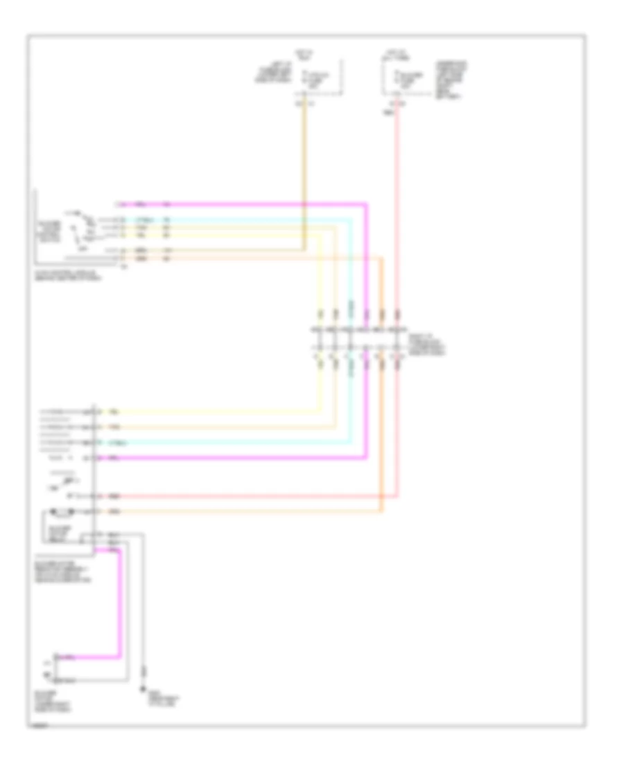
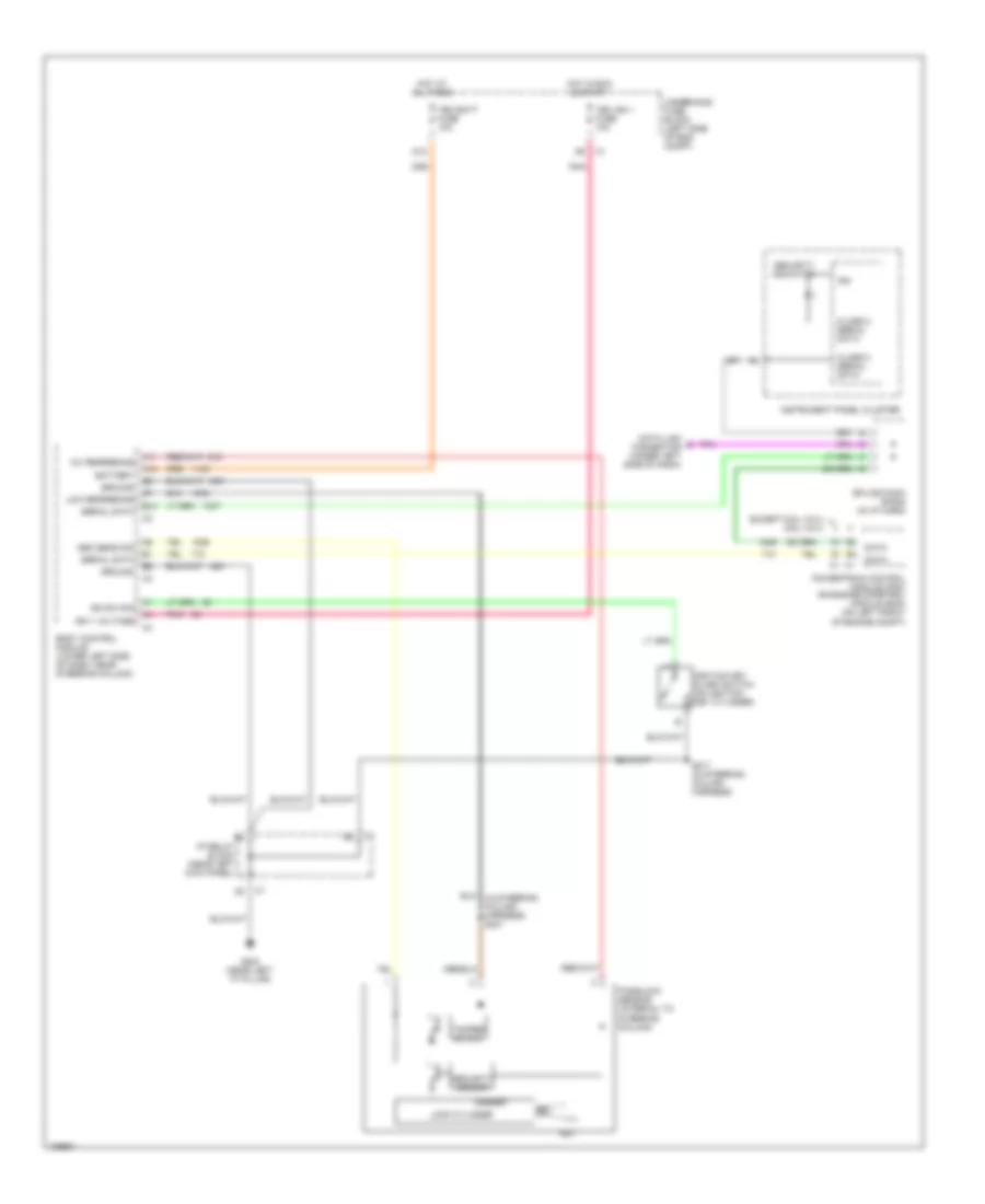
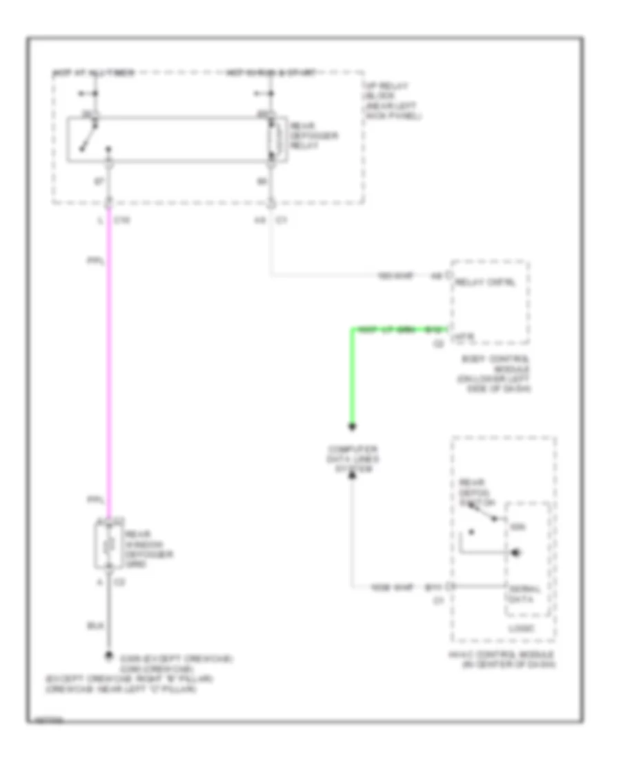
Rear Defogger Wiring Diagram for GMC Cab & Chassis Sierra 2004 3500
List of elements for Rear Defogger Wiring Diagram for GMC Cab & Chassis Sierra 2004 3500:
- (except crewcab: right "b" pillar) (crewcab: near left "c" pillar)
- A c1
- A c2
- A6 c1
- B11
- B12
- Body control module (on lower left side of dash)
- Computer data lines system
- G306 (except crewcab) g390 (crewcab)
- Hot at all times
- Hot in run & start
- Htr
- Hvac control module (in center of dash)
- I/p relay block (near left kick panel)
- Ign
- L c10
- Logic
- Rear defog switch
- Rear defogger relay
- Rear window defogger grid
- Relay cntrl
- Serial data
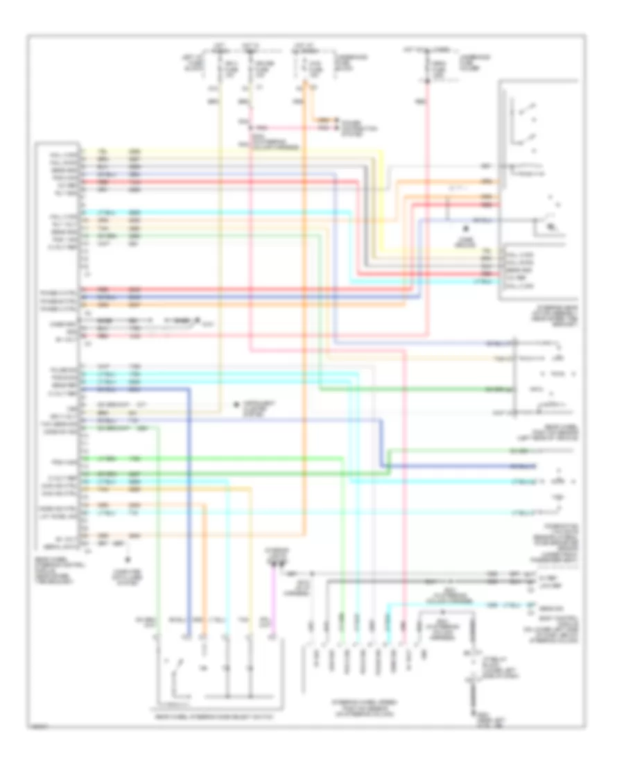
ELECTRONIC POWER STEERING
Electronic Power Steering Wiring Diagram for GMC Cab & Chassis Sierra 2004 3500
List of elements for Electronic Power Steering Wiring Diagram for GMC Cab & Chassis Sierra 2004 3500:
- 12v ref
- 2ws ind ctrl
- 4ws fuse 15a
- 4ws ind ctrl
- 5 volt ref
- 5v ref
- B+ volt
- B11
- Base
- Body control module (on lower left side of dash, below steering column)
- C1 b5
- C1 c5
- Case gnd
- Case ground
- Combination yaw rate sensor/lateral accelerometer sensor (under front passenger seat)
- Computer data lines system
- Cruise fuse 10a
- D12
- G101
- G203 (near left "a" pillar)
- Gnd
- Hall a sig
- Hall b sig
- Hall c sig
- Hot at all times
- Hot in run
- I/p relay block (lower left side of dash)
- Ign 3 fuse 10a
- Ign 3 volt
- Instrument cluster system
- Interior lights system
- Lat accel sig
- Left i/p fuse block
- Low ref
- Mega fuse 125a
- Mode ind ctrl
- Mode sw sig
- Phase a ctrl
- Phase b ctrl
- Phase c ctrl
- Pnk
- Pos 1 sig
- Pos 2 sig
- Pos a sig
- Pos b sig
- Power distribution system
- Pulse sig
- Rear wheel position sensor (left rear of vehicle)
- Rear wheel steering control module (near spare tire bracket)
- Rear wheel steering mode select switch
- Red
- Rly gnd
- Rly volt
- S212 (in i/p harness)
- S240 (in steering pnk column harness)
- S241 (in steering column harness)
- Sens gnd
- Sens ref
- Sens sig
- Serial data
- Steering gear motor assembly (near spare tire bracket)
- Steering wheel speed/ position sensor (on steering column)
- Tan
- Tan c
- Underhood fuse block
- Underhood fuse holder
- Vss
- Yaw sens sig
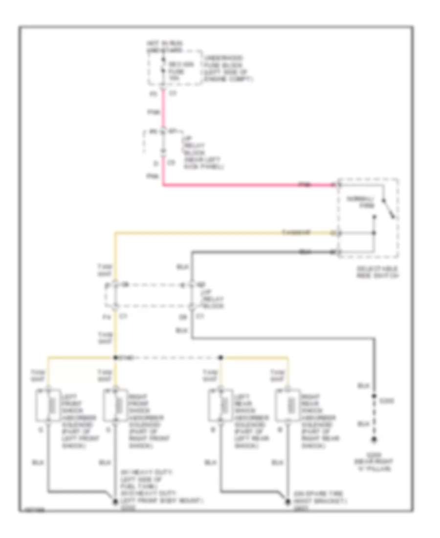
ELECTRONIC SUSPENSION
Electronic Suspension Wiring Diagram for GMC Cab & Chassis Sierra 2004 3500
List of elements for Electronic Suspension Wiring Diagram for GMC Cab & Chassis Sierra 2004 3500:
- (on spare tire hoist bracket) g401
- (w/ heavy duty: left side of fuel tank) (w/o heavy duty: left front body mount) g302
- G200 (near right "a" pillar)
- Hot in run and start
- I/p relay block
- I/p relay block (near left kick panel)
- Left front shock absorber solenoid (part of left front shock)
- Left rear shock absorber solenoid (part of left rear shock)
- Normal/ firm
- Pnk
- Right front shock absorber solenoid (part of right front shock)
- Right rear shock absorber solenoid (part of right rear shock)
- S140
- S202
- Selectable ride switch
- Seo ign fuse 10a
- Underhood fuse block (left side of engine compt)
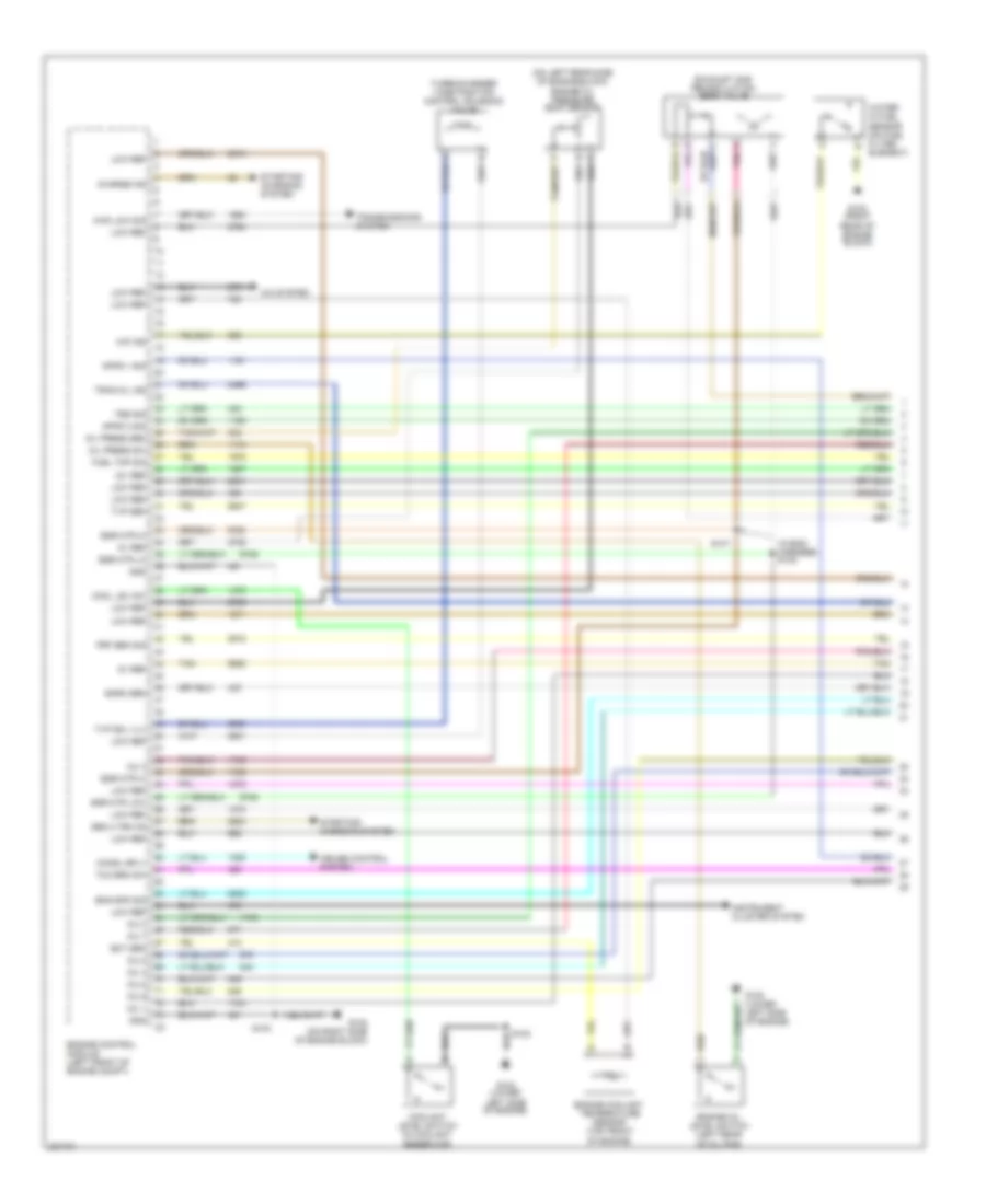
ENGINE PERFORMANCE
6.6L VIN 2
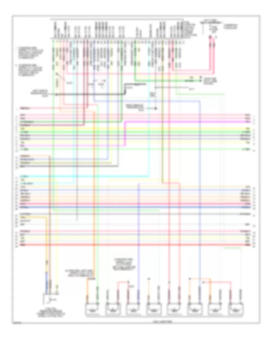
6.6L VIN 2, Engine Performance Wiring Diagram (1 of 6) for GMC Cab & Chassis Sierra 2004 3500
List of elements for 6.6L VIN 2, Engine Performance Wiring Diagram (1 of 6) for GMC Cab & Chassis Sierra 2004 3500:
- (in eng harness) s148
- (on left rear side of engine block) engine oil pressure (eop) sensor
- 12v ref
- 4wd low sig
- 5v ref
- A/c system
- Apps 1 sig
- Apps 3 sig
- Baro sen
- Charge ind
- Chmsl sply
- Cool lev sw
- Coolant level switch (in coolant reservoir)
- Cruise control system
- D pnk
- Ect sen
- Egr mtr hi
- Egr mtr lo
- Egr mtr low
- Eng spd sig
- Engine control module (left front of engine compt)
- Engine coolant temperature sensor (top front of engine)
- Engine oil level switch (left rear of oil pan)
- Exhaust gas recirculation (egr) valve
- Frp sen sig
- Fuel tmp sig
- G102 (on right side of engine block)
- G103 (right rear of engine block)
- G104 (lower left side of engine)
- G108 (lower left side of engine)
- Gen 2 trn on
- Gnd
- Inj 1
- Inj 2
- Inj 3
- Inj 4
- Inj 5
- Inj 6
- Inj 7
- Inj 8
- Instrument cluster system
- Low ref
- Oil press sen
- Oil press sw
- S102
- S103
- S147
- Starting/ charging system
- Tan
- Tbs sig
- Tcc brk sw
- Tran mil ind
- Transmissions system
- Turbocharger vane position control solenoid valve
- Tvp sen
- Tvp sol vlv
- Water in fuel sensor (on fuel filter element)
- Wif ind
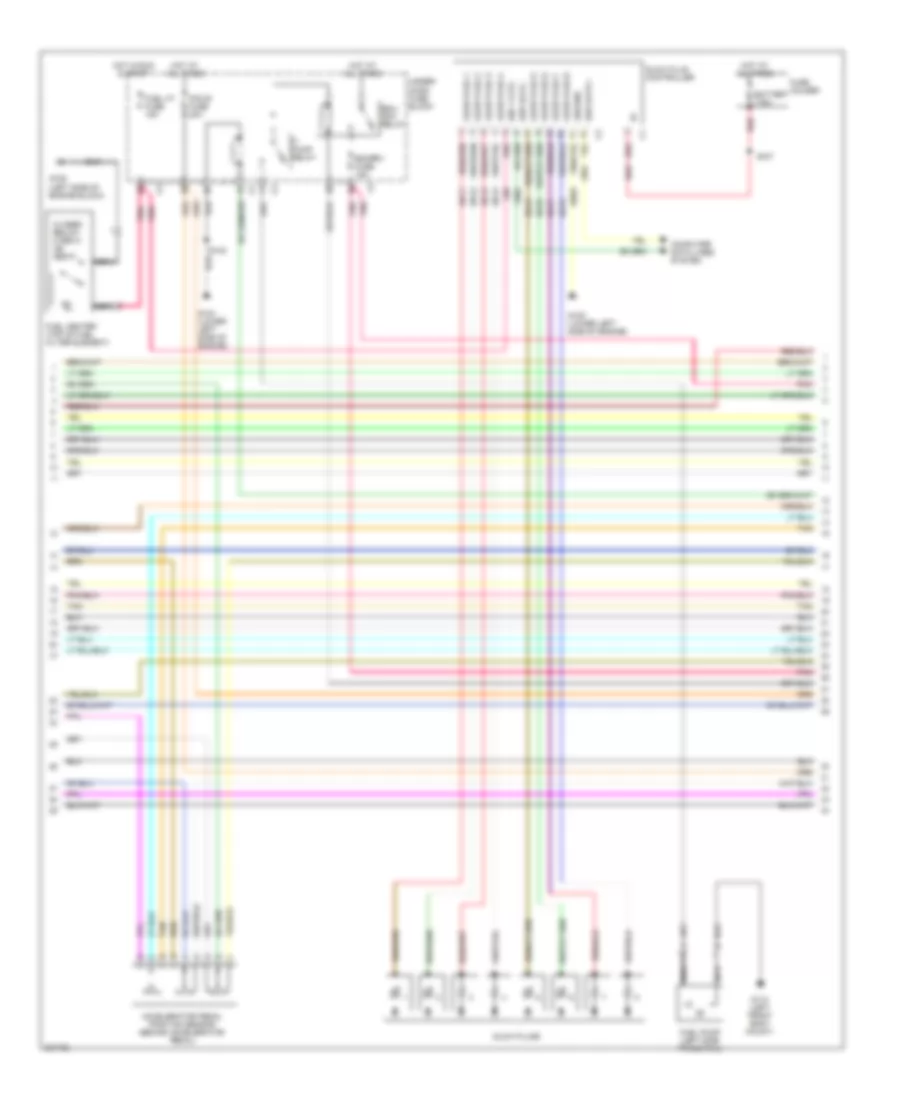
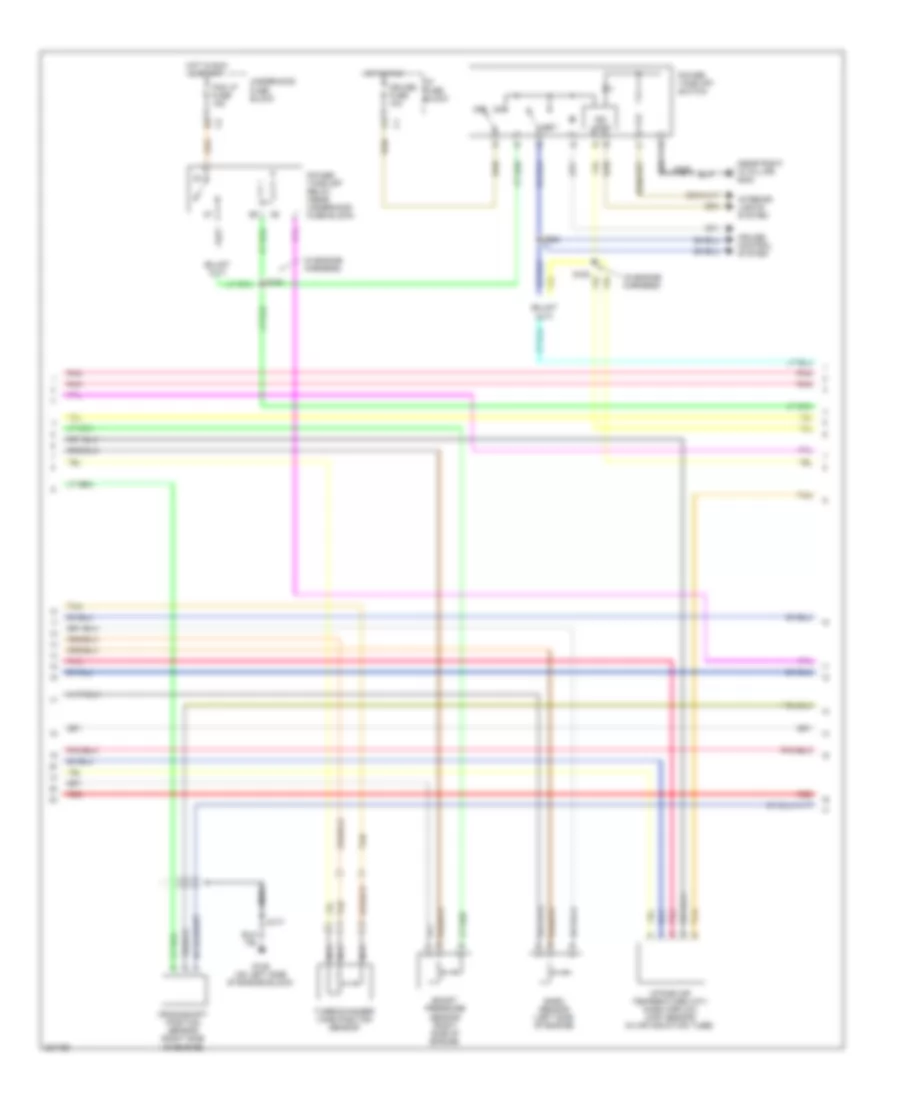
6.6L VIN 2, Engine Performance Wiring Diagram (2 of 6) for GMC Cab & Chassis Sierra 2004 3500
List of elements for 6.6L VIN 2, Engine Performance Wiring Diagram (2 of 6) for GMC Cab & Chassis Sierra 2004 3500:
- Accelerator pedal position sensor (behind accelerator pedal)
- Battery 175a
- Closed below 8 deg c (46 deg f)
- Computer data lines system
- Ecmprv fuse 15a
- Edu/ ign1 relay
- F/ pump relay
- Fuel heater (top of fuel filter element)
- Fuel ht fuse 15a
- Fuel pump (left side frame rail)
- Fuse holder
- G104 (lower left side of engine)
- G108 (lower left side of engine)
- G109 (left side of engine block)
- G110 (left front body mount)
- Glow plug 1
- Glow plug 2
- Glow plug 3
- Glow plug 4
- Glow plug 5
- Glow plug 6
- Glow plug 7
- Glow plug 8
- Glow plug controller
- Glow plugs
- Ground
- Hb03
- Hb11
- Hb12
- Hb13
- Hb14
- Hb15
- Hb16
- Hb17
- Hb18
- Hot at all times
- Hot in run & start
- Ign 1 vltg
- Nca
- Pcm b fuse 20a
- Pnk
- Red
- S102
- S127
- Ser data +
- Ser data -
- Tan
- Under- hood fuse block
6.6L VIN 2, Engine Performance Wiring Diagram (3 of 6) for GMC Cab & Chassis Sierra 2004 3500
List of elements for 6.6L VIN 2, Engine Performance Wiring Diagram (3 of 6) for GMC Cab & Chassis Sierra 2004 3500:
- (on right side of engine block) g102
- 12v ref
- 5v ref
- A/c
- Abs system
- Apps 2 sig
- Body relay block
- Brake fuse 10a
- C12
- Class 2 data
- Clutch pedal position switch (top of pedal bracket)
- Computer data lines system
- Crank fuse 10a
- E11
- Ecm 1 fuse 15a
- Egr vlv pos
- Engine control module (left front of engine compt)
- Ficm rly ctrl
- Fp reg sol
- Fuel lev sen
- Fuel pmp rly
- Fuel pressure regulator
- G103 (on right rear of engine block)
- Gen fdc dig
- Gnd
- Hot in off, run & start
- Hot in run
- Hot in run & start
- Hot in start
- I/p fuse block
- Ign vlt
- Ign 0 fuse 10a c1
- Ign 0 vlt
- Ign 1 vlt
- Instrument cluster system
- Low ref
- Maf sens
- Nca
- Pnk
- Red
- S103
- S141
- S142
- S143
- S144
- S174
- Ser data +
- Ser data -
- Starting/charging system
- Stoplamp switch (top of brake pedal bracket)
- System
- Tan
- Under- hood fuse block
- Vss
- Wts ind
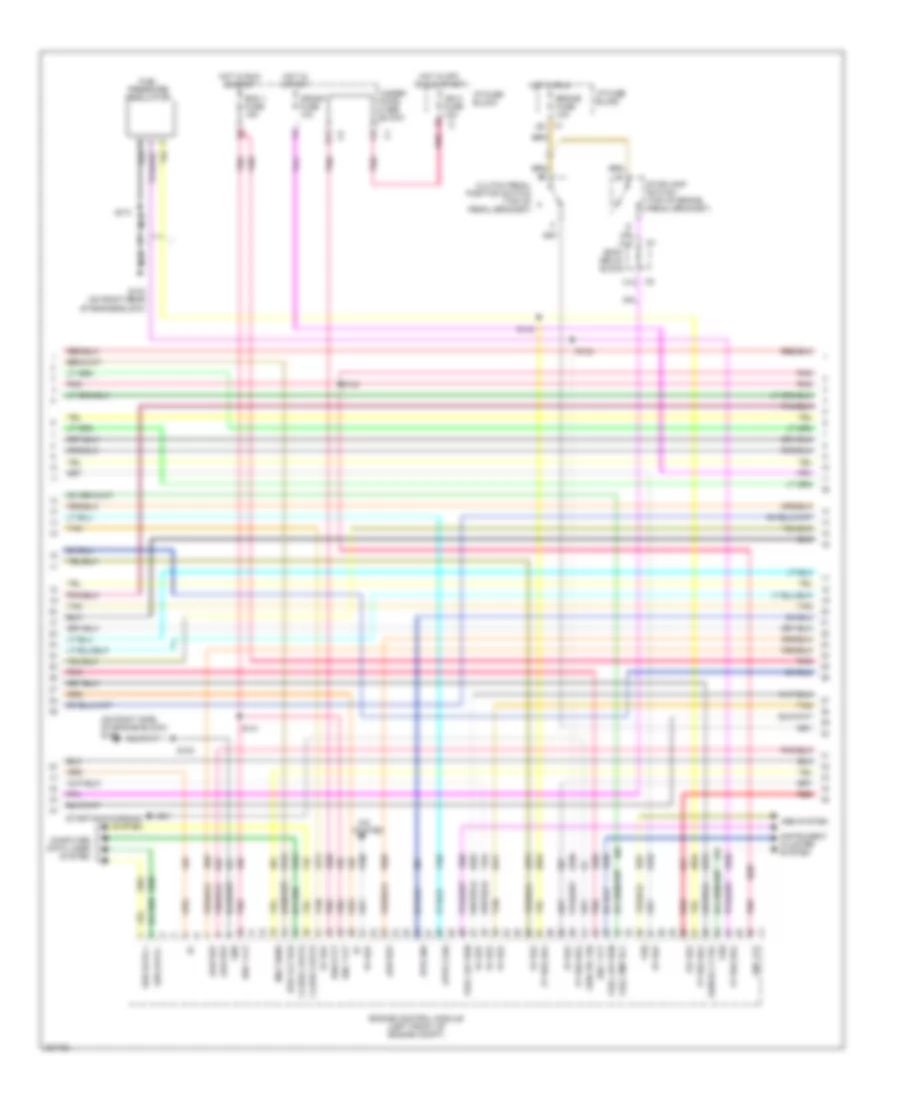
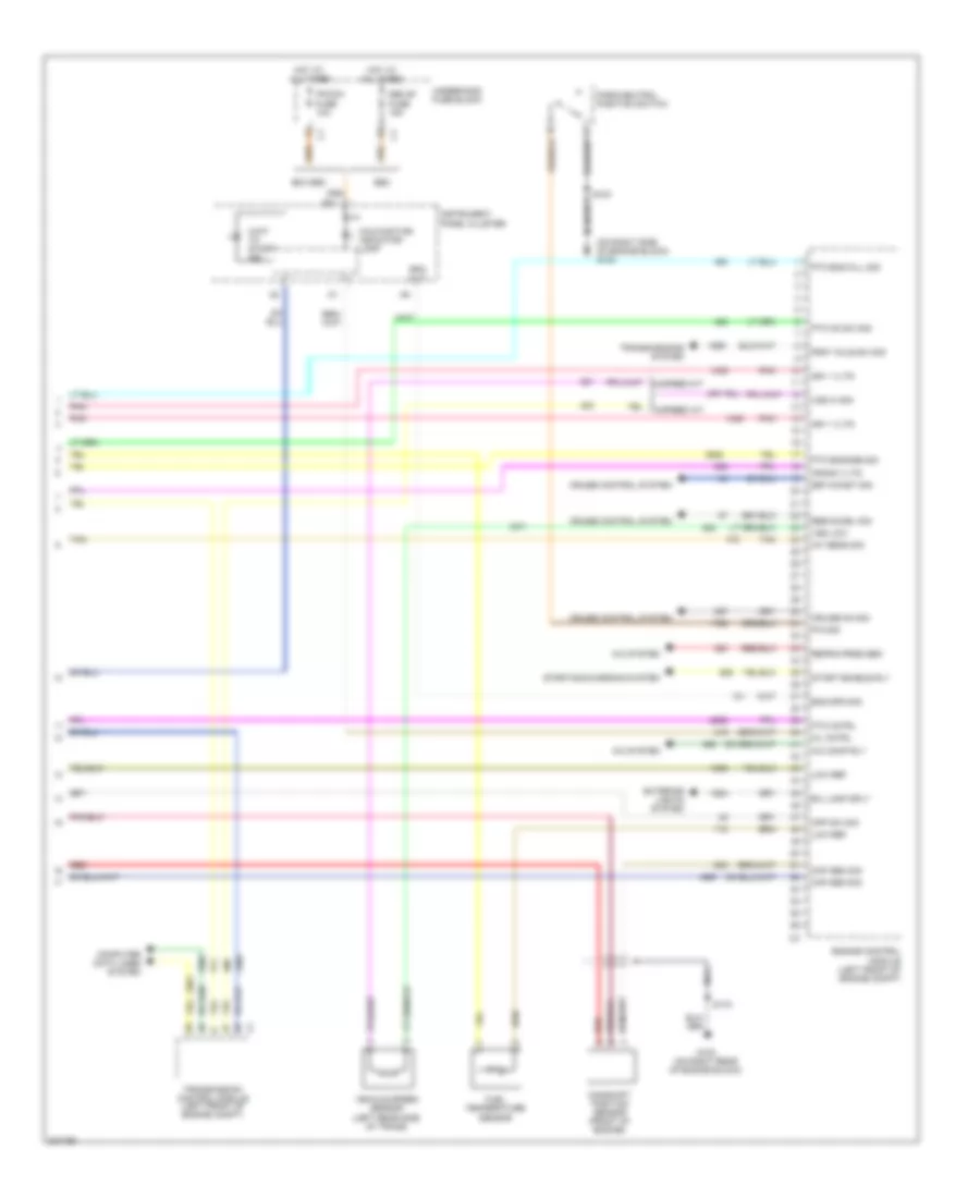
6.6L VIN 2, Engine Performance Wiring Diagram (4 of 6) for GMC Cab & Chassis Sierra 2004 3500
List of elements for 6.6L VIN 2, Engine Performance Wiring Diagram (4 of 6) for GMC Cab & Chassis Sierra 2004 3500:
- (in engine harn,
- (in engine harn, approx 13 cm (5.12 in) from left fuel injector bank breakout)
- (in forward lamp harn, approx 5 cm (1.97 in) from c104 breakout)
- (left side of engine block)
- (pins 49-58 not used)
- (pins 6-43 not used)
- (pins 68-81 not used)
- (pins 82-89 not used)
- (pins 95-113 not used)
- (right rear of engine block)
- Approx 10.16 cm (4 in) from fuel injector control module c1 breakout)
- Approx 12.7 cm (5 in) from fuel injector control module c1 breakout)
- Can hi
- Can low
- Computer data lines system
- Engine spd
- Fuel injector control module (under air intake duct)
- Fuel injectors
- Fuel rail pressure sensor (under intake manifold shield, on fuel rail)
- G103
- G109
- Ground
- Hot w/ edu relay energized
- Ic13
- Ic15
- Ic16
- Ic17
- Ic18
- Ic19
- Ic20
- Ic21
- Ic22
- Ic520
- Ic521
- Ic60
- Ign
- Ign 1 vltg
- Ign 2,3,5,8
- Inj 1 ctrl
- Inj 2 ctrl
- Inj 3 ctrl
- Inj 4 ctrl
- Inj 5 ctrl
- Inj 6 ctrl
- Inj 7 ctrl
- Inj 8 ctrl
- Inj1 command
- Inj2 command
- Inj3 command
- Inj4 command
- Inj5 command'
- Inj6 command
- Inj7 command
- Inj8 command
- Injb fuse 25a
- Iz17
- Iz18
- Nca
- Pnk
- Red
- S166
- S167
- S168
- S169
- S171
- S175
- S176
- Tan
- Underhood fuse block
6.6L VIN 2, Engine Performance Wiring Diagram (5 of 6) for GMC Cab & Chassis Sierra 2004 3500
List of elements for 6.6L VIN 2, Engine Performance Wiring Diagram (5 of 6) for GMC Cab & Chassis Sierra 2004 3500:
- (in engine harness)
- (near right "a" pillar) g200
- Baro sensor (left side of engine)
- Boost pressure sensor (right side of engine)
- Crankshaft position sensor (right side of engine)
- Cruise control system
- Cruise fuse 10a
- Fog lp fuse 15a
- G109 (on left side of engine block)
- Hot in run
- Hot in run & start
- I/p fuse block
- Ind logic
- Intake air temperature (iat)/ mass airflow (maf) sensor (in air induction tube)
- Interior lights system
- Nca
- Off
- Pnk
- Power take off relay (near underhood fuse block)
- Power take off switch
- Red
- S163
- S177
- S205
- S224
- Set
- Tan
- Turbochanger vane position sensor
- Underhood fuse block
6.6L VIN 2, Engine Performance Wiring Diagram (6 of 6) for GMC Cab & Chassis Sierra 2004 3500
List of elements for 6.6L VIN 2, Engine Performance Wiring Diagram (6 of 6) for GMC Cab & Chassis Sierra 2004 3500:
- (m/t)
- (on right side of engine block) g102
- 5-speed a/t
- 6-speed m/t
- A/c comp rly
- A/c system
- B/u lamp sply
- B11
- Camshaft position sensor (front of engine)
- Ckp sen sig
- Computer data lines system
- Cpp sw sig
- Crank vltg
- Cruise control system
- Cruise on sig
- Eng spd sig
- Engine control module (left front of engine compt)
- Exc seo
- Exterior lights system
- Frnt axle sw sig
- Fuel temperature sensor
- G103 (on right rear of engine block)
- Hot at all times
- Iat sens sig
- Ign 1 vltg
- Instrument panel cluster
- Ipc/dic fuse 10a
- Low ref
- Malfunction indicator lamp
- Mil cntrl
- Nca
- P/n sig
- Park/neutral position switch
- Pnk
- Pto cntrl
- Pto eng kill sig
- Pto engage sig
- Pto on sw sig
- Red
- Refrig prss sen
- Res/accel sig
- Rpm out
- S103
- S170
- Seo
- Seo b1 fuse 15a
- Set/coast sig
- Start enable rly
- Starting/charging system
- Tan
- Transmission control module (left front of engine compt)
- Transmissions system
- Underhood fuse block
- Vehicle speed sensor (left rear side of trans)
- Vss hi sig
- Vss low
- Wait to start ind
EXTERIOR LIGHTS
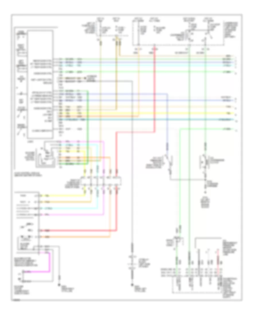
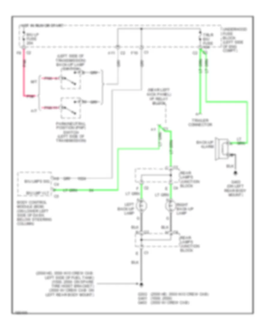
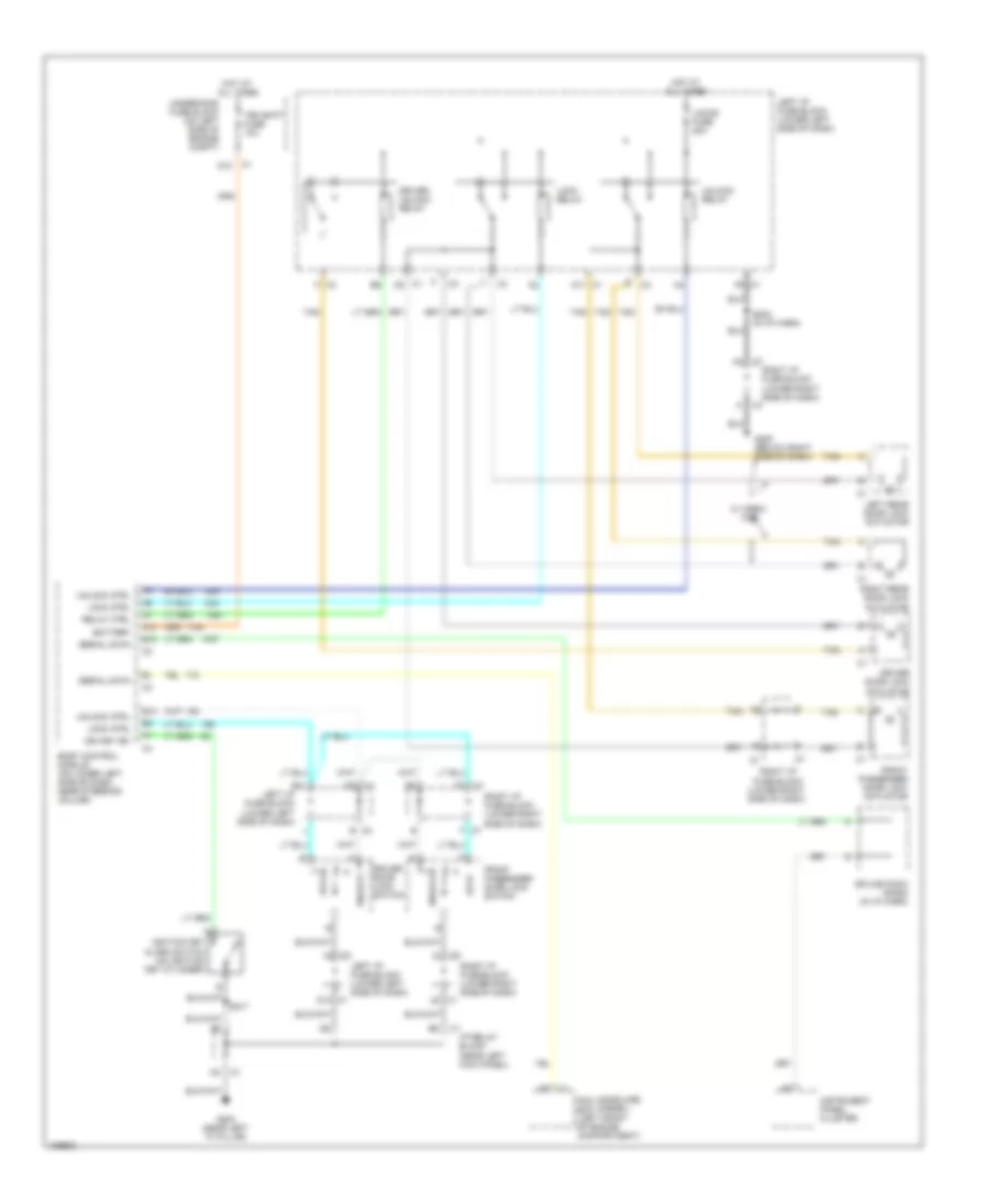
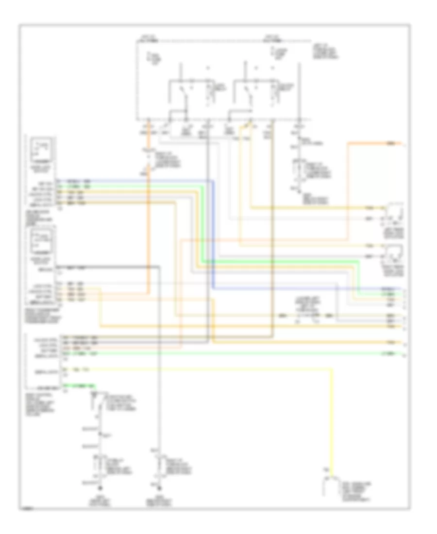
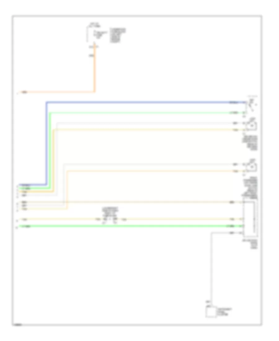
Back-up Lamps Wiring Diagram for GMC Cab & Chassis Sierra 2004 3500
List of elements for Back-up Lamps Wiring Diagram for GMC Cab & Chassis Sierra 2004 3500:
- (2500 hd, 3500 w/o crew cab) (1500, 2500) (3500 w/ crew cab)
- (2500 hd, 3500 w/o crew cab: left side of fuel tank) (1500, 2500: on spare tire hoist bracket) (3500 w/ crew cab: on left rear body mount)
- (left side of transmission) back-up lamp switch
- (near left kick panel) i/p relay block
- A/t
- A11
- B/u lmp vlt
- B/u lmps sig
- B/u lp fuse 20a
- Back-up alarm
- Body control module (bcm) (on lower left side of dash, below steering column)
- F10
- G302 g401 g403
- G403 (on left rear body mount)
- Hot in run or start
- Left back-up lamp
- M/t
- Park/neutral position (pnp) switch (left side of transmission)
- Pnk
- Rear lamps junction block
- Right back-up lamp
- Trailer connector
- Trlr b/u fuse 10a
- Underhood fuse block (left side of eng compt)
Exterior Lamps Wiring Diagram (1 of 3) for GMC Cab & Chassis Sierra 2004 3500
List of elements for Exterior Lamps Wiring Diagram (1 of 3) for GMC Cab & Chassis Sierra 2004 3500:
- (2500 hd, 3500 w/o crew cab) (1500, 2500) (3500 w/ crew cab)
- (2500 hd, 3500 w/o crew cab: left side of fuel tank) (1500, 2500: on spare tire hoist bracket) (3500 w/ crew cab: on left rear body mount)
- Anl/
- Auto
- Back-up lamps circuit
- Body control module (bcm) (on lower left side of dash, below steering column)
- C2 b2
- Computer data lines system
- D10
- Drl
- Emergency vehicle roof lamp relay
- F11
- Frt park fuse 10a
- G100 (lower left radiator support)
- G200 (behind right side of dash, near right "a" pillar)
- G203 (behind left side of dash, near left "a" pillar)
- G302 g401 g403
- G403 (on left rear body mount)
- Hazard switch
- Head
- Headlamp switch
- Hot at all times
- Hot in run and start
- I/p relay block
- Ign e fuse 10a
- Left
- Left front marker lamp
- Left front park/ turn signal lamp
- Park
- Park lamp relay
- Pnk
- Prk lmp on
- Prk lmp rly
- Red
- Right
- Right front marker lamp
- Right front park/ turn signal lamp
- S100
- S101
- S215
- S217
- Serial data
- Stud 1 fuse 40a
- Stud 2 fuse 30a
- To trl park fuse (diagram 2 0f 3)
- Trailer connector
- Turn signal/ multi- function switch
- Under- hood fuse block (on left side of engine compt)
Exterior Lamps Wiring Diagram (2 of 3) for GMC Cab & Chassis Sierra 2004 3500
List of elements for Exterior Lamps Wiring Diagram (2 of 3) for GMC Cab & Chassis Sierra 2004 3500:
- (2500 hd, 3500 w/o crew cab) (1500, 2500) (3500 w/ crew cab)
- (2500 hd, 3500 w/o crew cab: left side of fuel tank) (1500, 2500: on spare tire hoist bracket) (3500 w/ crew cab: on left rear body mount)
- (except w/ 4-wheel steering)
- (in brake clutch harn)
- (w/ roof marker lamps)
- (w/ 4-wheel steering)
- (w/ pto)
- A12
- Beacon lighting
- C1 b
- C1 d
- C1 g
- C1 h
- C2 d
- C3 b6
- C3 d
- C3 h
- C4 f
- D12
- E11
- F12
- From a frt park fuse (diagram 1 0f 3)
- G302 g401 g403
- G304 (except crewcab) (under right front seat)
- G305 (crewcab) (on left "b" pillar)
- Hot at all times
- I/p relay block
- Int park fuse 10a
- Interior lights system
- Left front clear- ance lamp
- Left license lamp
- Left rear clear- ance lamp
- Left rear turn signal
- Left tail/ stop- lamp
- Lr park fuse 10a
- Rear lamps junction block
- Red
- Right front clear- ance lamp
- Right i/p fuse block
- Right license lamp
- Right rear clear- ance lamp
- Right rear turn signal
- Right tail/ stop- lamp
- Roof beacon relay (at lower left "b" pillar
- Roof beacon switch
- Rr park fuse 10a
- S206 (in i/p harn)
- S215
- S219
- S420
- S421
- S422
- S423
- S424
- Seo b1 fuse 15a
- Seo b2 fuse 30a
- Stop lp fuse 25a
- Stop- lamp switch
- Tailgate marker lamp
- Trl park fuse 15a
- Under- hood fuse block (on left side of engine compt)
- Vehicle roof lamp lighting
- W/ emergency
- W/ roof
Exterior Lamps Wiring Diagram (3 of 3) for GMC Cab & Chassis Sierra 2004 3500
List of elements for Exterior Lamps Wiring Diagram (3 of 3) for GMC Cab & Chassis Sierra 2004 3500:
- (behind right side of dash, near right "a" pillar)
- (behind right side of dash, near right "a" pillar) g200
- (w/ level 3 convenience package)
- A11
- Battery
- C10
- C3 e1
- C6 right i/p fuse block
- Center high mounted stop lamp (chmsl)
- Clearance lamps
- Computer data lines system
- D10
- Driver door module (ddm) (in driver's door)
- Driver outside rearview mirror
- E10
- Ext- erior illum lamp
- F10
- Flash fuse 25a
- Front passenger door module (fpdm) (in right front door)
- G200
- G200 (behind right side of dash, near right "a" pillar)
- G203 (behind left side of dash, near left "a" pillar)
- Ground
- Hazard sw
- Hot at all times
- I/p relay block
- I/p relay block (near left kick panel)
- Instrument panel cluster (ipc)
- Left i/p fuse block (on lower left side of dash)
- Left roof l marker lamp
- Left turn ind
- Logic
- Lr lamp volt
- Lt door lmp gnd
- Lt door lmp pwr
- Lt trlr st/trn fuse 10a
- Lt turn fuse 10a
- Lt turn sig
- Lt turn sig volt
- Nca
- Passenger outside rearview mirror
- Red
- Right i/p fuse block
- Right roof r marker lamp
- Right turn ind
- Rr lamp volt
- Rt door lmp gnd
- Rt door lmp pwr
- Rt trlr st/trn fuse 10a
- Rt turn fuse 10a
- Rt turn sig
- Rt turn sig volt
- S200 (at roof marker harness)
- S201 (at roof marker harness)
- S202
- S205
- S207
- Serial data
- Stoplamp sw
- Tan
- Turn ind
- Turn signal/flasher module
- Under- hood fuse block
- Veh chmsl fuse 10a
- Veh stop fuse 15a
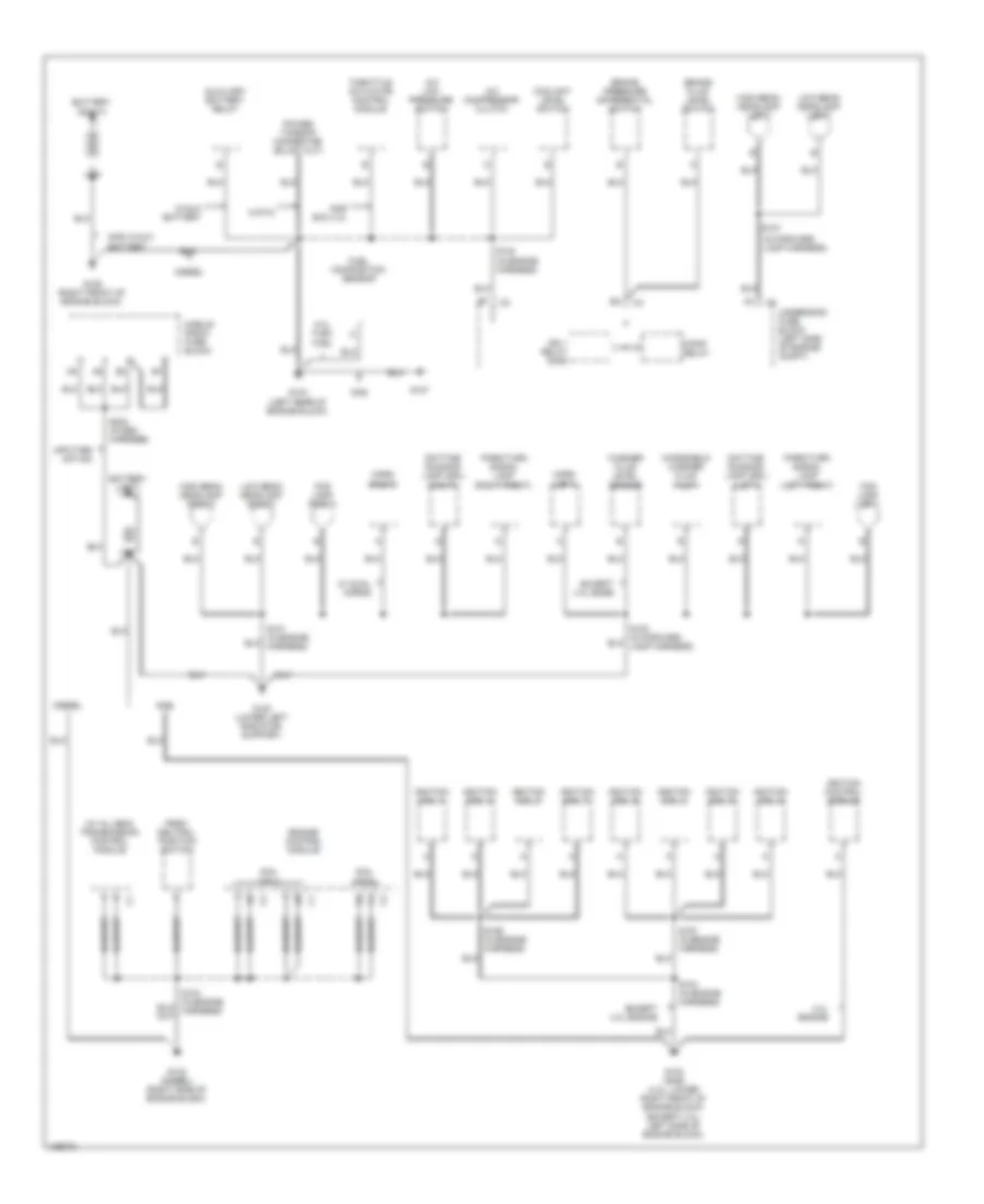
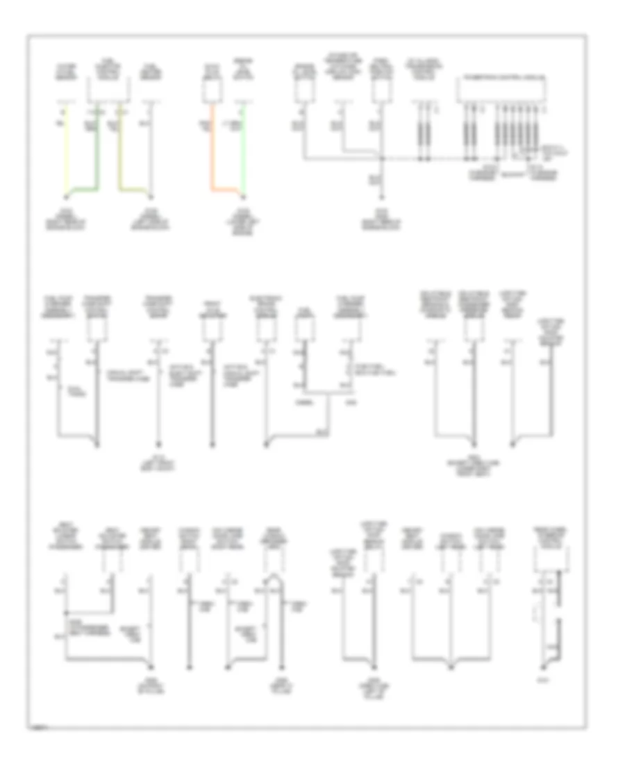
GROUND DISTRIBUTION
Ground Distribution Wiring Diagram (1 of 4) for GMC Cab & Chassis Sierra 2004 3500
List of elements for Ground Distribution Wiring Diagram (1 of 4) for GMC Cab & Chassis Sierra 2004 3500:
- (6.6l vin 1)
- (6.6l vin 2)
- (in forward lamp harness)
- (w/ allison) transmission control module
- 4.3l engine
- 5.3l flex fuel
- A/c compressor clutch
- A/c low pressure switch
- Auxiliary battery relay
- Battery (left)
- Battery (right)
- Brake fluid level switch
- Brake pressure differential switch
- Coolant level switch
- Daytime running lamp (drl) (left)
- Daytime running lamp (drl) (right)
- Diesel
- Engine control module
- Except 4.3l base
- Except 4.3l engine
- F/pmp relay
- Fog lamp (left)
- Fog lamp (right)
- Fuel composition sensor
- G100 (lower left radiator support)
- G102 (diesel) (right side of engine block)
- G102 (gas) (4.3l: lower right front of engine block) (except 4.3l: left side of engine block)
- G104 (left rear of engine block)
- G106 (right front of engine block)
- G107
- Gas
- Gas exc 4.3l
- Gas w/aux battery
- High beam headlamp (left)
- High beam headlamp (right)
- Horn (left)
- Horn (right)
- Ign 1 relay (gas)
- Ignition coil 1
- Ignition coil 2
- Ignition coil 3
- Ignition coil 4
- Ignition coil 5
- Ignition coil 6
- Ignition coil 7
- Ignition coil 8
- Ignition control module
- Low beam headlamp (left)
- Low beam headlamp (right)
- Mobile radio fuse block
- Park/ neutral position switch
- Park/turn signal lamp (left front)
- Park/turn signal lamp (right front)
- S102 (in engine harness)
- S104 (in engine harness)
- S107
- S156 (in engine harness)
- S157 (in engine harness)
- S223 (in seo harness)
- Throttle actuator control module
- Underhood fuse block (left side of engine compt)
- Upfitter option
- W/ dual horns
- W/aux battery
- W/pto
- Washer fluid level sensor
- Windshield washer fluid pump
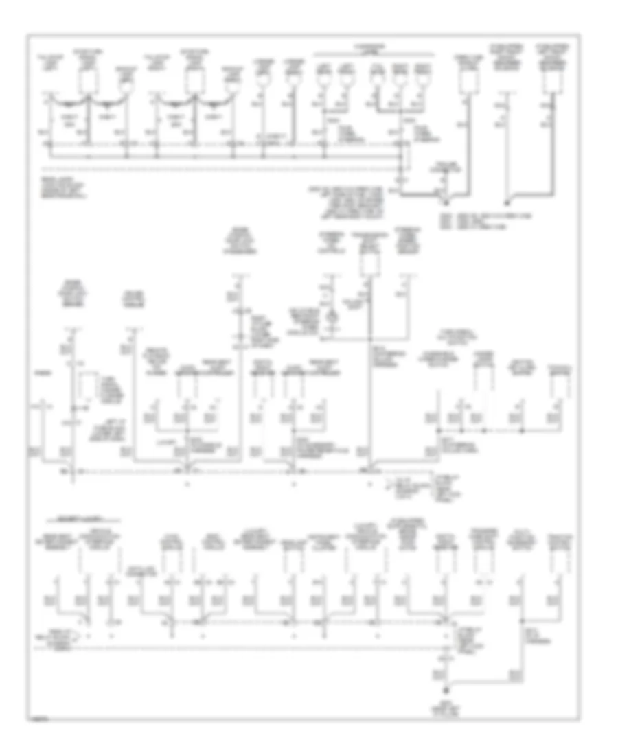
Ground Distribution Wiring Diagram (2 of 4) for GMC Cab & Chassis Sierra 2004 3500
List of elements for Ground Distribution Wiring Diagram (2 of 4) for GMC Cab & Chassis Sierra 2004 3500:
- (exc flex fuel) c
- (flex fuel)
- (upfitter option) roof beacon relay
- (upfitter option) roof mounted beacon
- (w/ allison) transmission control module
- Active & elect shift transfer case
- Active & manual shift transfer case
- C1 a
- C2 a
- C2 d
- C3 a
- Crew cab
- Diesel
- Dual tanks
- Electronic brake control module
- Engine oil level switch
- Exc 8.1l w/o calif lev
- Except crew cab
- Front axle actuator
- Fuel heater sensor
- Fuel injector control module
- Fuel pump
- Fuel pump & sender assembly (secondary)
- G101
- G103 (diesel) (right rear of engine block)
- G103 (gas) (right rear of engine block)
- G108 (diesel) (lower left side of engine)
- G109 (diesel) (left side of engine block)
- G110 (left front body mount)
- G304 (except crew cab) (under right front seat)
- G305 (crew cab) (left "b" pillar)
- G306 (on right "b" pillar)
- G390 (near "c" pillar)
- Gas
- Glow plug relay
- Inflatable restraint passenger presense module
- Inflatable restraint sensing & diagnostic module
- Intake air temperature (iat)/mass airflow (maf) sensor
- Manual shift transfer case
- Memory seat module (driver)
- Mini wedge (door jamb switch) (left rear)
- Mini wedge (door jamb switch) (right rear)
- Nca
- Park/ neutral position switch
- Powertrain control module
- Rear wheel steering control module
- Rear window defogger grid
- S103 (in engine harness)
- S110 (in engine harness)
- S329 (in passenger seat harness)
- Seat adjuster switch (passenger)
- Seat bolster/ lumbar switch (passenger)
- Transfer case shift control motor
- Transfer case shift control switch
- Water in fuel sensor
- Window switch (right rear)
- Window switch) (left rear)
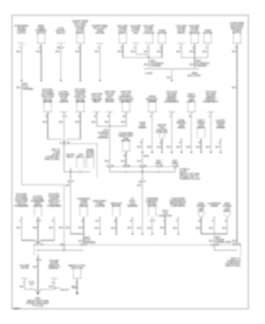
Ground Distribution Wiring Diagram (3 of 4) for GMC Cab & Chassis Sierra 2004 3500
List of elements for Ground Distribution Wiring Diagram (3 of 4) for GMC Cab & Chassis Sierra 2004 3500:
- (2500 hd, 3500 w/o crew cab) (1500, 2500) (3500 w/ crew cab)
- (2500 hd, 3500 w/o crew cab: left side of fuel tank) (1500, 2500: on spare tire hoist bracket) (3500 w/ crew cab: on left rear body mount)
- (base) window/ door lock switch (driver)
- (base) window/ door lock switch (passenger)
- (crew cab) backup alarm
- (except luxury)
- (if equipped) left front shock absorber solenoid
- (if equipped) right front shock absorber solenoid
- (left front)
- (left rear)
- (luxury) rear seat entertainment assembly
- (luxury) vehicle communication interface module
- (right front)
- (right rear)
- (tail gate)
- A12
- Audio amplifier
- B12
- Backup lamp (left)
- Backup lamp (right)
- Body control module
- C (gmc)
- C1 2c
- C1 a8
- C1 c5
- C1 d10
- C1 e
- C2 a
- C2 b6
- C3 b6
- Chevy
- Clearance lamps
- Column shift
- Cruise control module
- Data link connector
- Digital radio receiver
- E (chevy)
- Four wheel steering
- From i/p relay block a (diagram 3 of 4)
- G203 (near left "a" pillar)
- G302 g401 g403
- Gmc
- Hazard lamps switch
- Headlamp switch
- Hvac control module
- I/p relay block (near left kick panel)
- Ignition key alarm switch
- Inflatable restraint steering wheel module coil
- Instrument panel cluster
- Left i/p fuse block (lower left side of dash)
- License lamp (left)
- License lamp (right)
- Luxury
- Multi- function accessory switch
- Nca
- Radio
- Rear lamps junction block (inside of left rear frame rail)
- Rear seat audio controller
- Rear seat entertainment assembly
- Remote playback device (cd player)
- Right i/p fuse block (lower right side of dash)
- S213 (in i/p harness)
- S216 (in steering column harness)
- S217 (in steering column harn)
- S423
- S424
- Steering wheel dic controls
- Steering wheel speed/ position sensor
- Stop/turn signal lamp (right)
- Stop/turn signal lamp) (left)
- Tail/stop lamp (left)
- Tail/stop lamp (right)
- To i/p relay block (diagram 3 of 4)
- Tow/haul switch
- Traction control switch
- Trailer connector
- Transfer case shift control module
- Transmission shift select switch
- Turn signal hazard flasher module
- Turn signal/ multifunction switch
- Vehicle communication interface module
- Windshield wiper/washer switch
Ground Distribution Wiring Diagram (4 of 4) for GMC Cab & Chassis Sierra 2004 3500
List of elements for Ground Distribution Wiring Diagram (4 of 4) for GMC Cab & Chassis Sierra 2004 3500:
- (auto a/c) air temp sensor assembly (inside front)
- (auto a/c) air temp sensor assembly (inside rear)
- (base) driver unlock relay
- (except bose or luxury) auxiliary power outlet (front)
- (except bose or luxury) cigar lighter
- (if equipped) inflatable restraint disable switch
- (if equipped) power takeoff switch
- (if equipped) selectable ride switch
- (luxury) garage door opener
- (not used)
- (upfitter option) emergency vehicle roof lamp relay
- (upfitter option) roof beacon switch
- (upfitter option) wrecker relay
- (w conv package) driver door module
- (w conv package) passenger door module
- (w/o conv package) mini wedge door jamb switch (driver)
- (w/o conv package) mini wedge door jamb switch (passenger)
- (w/o conv package) window/ door lock switch (driver)
- (w/o conv package) window/ door lock switch (passenger)
- A/t shift lock solenoid
- A12
- Auto a/c
- Auxiliary power outlet (bin)
- Auxiliary power outlet (console)
- Auxiliary power outlet (front)
- Blower motor
- Blower motor resistor assembly
- Bose exc luxury
- C1 6c
- C1 a
- C1 b9
- C1 d9
- C1 f6
- C3 c
- C4 a
- C5 e
- C7 f
- C8 f
- C9 a
- Center high mounted stop lamp
- Cigar lighter
- Clearance lamps
- Data link connector
- Dome lamp (front)
- Dome/ reading lamp (rear)
- G200 (behind right side of dash, near right "a" pillar)
- Headlamp switch
- Hvac control module
- I/p relay block (below left side of dash, left of steering column)
- Inside rearview mirror
- Instrument panel cluster
- Left i/p fuse block (lower left side of dash)
- Lock relay
- Luxury
- Man a/c
- Rear wheel steering switch
- Recirculation actuator
- Right i/p fuse block (lower right side of dash)
- Roof marker lamp (left)
- Roof marker lamp (right)
- S205
- S215 (in brake clutch harness)
- S345
- Transfer case shift control switch
- Unlock relay
- Vanity mirror lamp (left)
- Vanity mirror lamp (right)
- Windshield wiper motor module
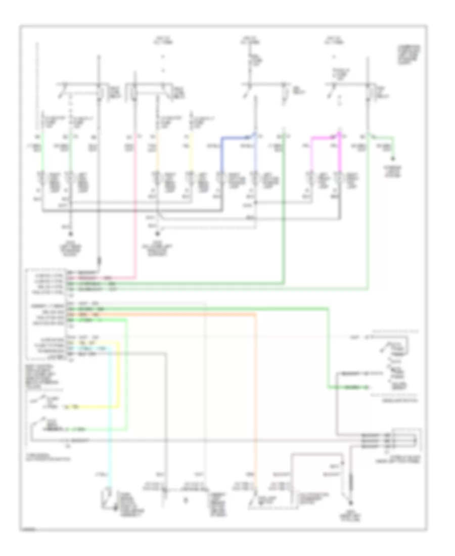
HEADLIGHTS
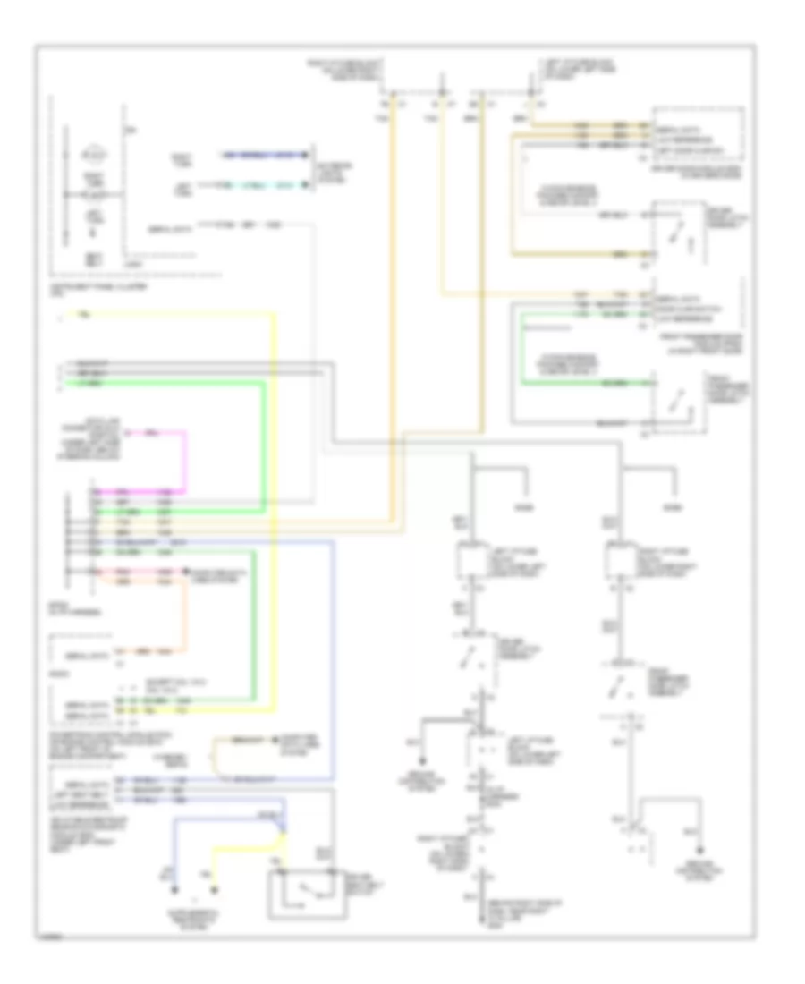
Headlights Wiring Diagram for GMC Cab & Chassis Sierra 2004 3500
List of elements for Headlights Wiring Diagram for GMC Cab & Chassis Sierra 2004 3500:
- (w/ cj2)
- (w/ t89)
- (w/o cj2)
- (w/o t89)
- A12
- Ambient light sensor (on top center of dash)
- Ambient lt sens
- Anl/drl defeat
- Auto
- Body control module (bcm) (on lower left side of dash, below steering column)
- Drl fuse 10a
- Drl relay
- Drl rly ctrl
- Drl sw sig
- Flash to pass
- Fog lamp switch
- Fog lp fuse 15a
- Fog lp relay
- Fog lp rly ctrl
- Fog lp sw sig
- G100 (on lower left radiator support)
- G104 (left rear of engine block)
- G203 (near left "a" pillar)
- Hdlp dim sw sig
- Hdlp hi bm relay
- Hdlp lo bm relay
- Head
- Headlamp switch
- Hi bm rly ctrl
- Hi hdlp lt fuse 10a
- Hi hdlp rt fuse 10a
- Hi/lo beam select
- Hlps on sig
- Hot at all times
- I/p relay block (near left kick panel)
- Interior lights system
- Left daytime running lamp
- Left front fog lamp
- Left high beam head- lamp
- Left low beam head- lamp
- Lo bm rly ctrl
- Lo hdlp lt fuse 10a
- Lo hdlp rt fuse 10a
- Low ref
- Multifunction accessory switch
- Park
- Park brake switch (part of park brake assembly)
- Pk brake sig
- Right daytime running lamp
- Right front fog lamp
- Right high beam head- lamp
- Right low beam head- lamp
- S100
- S101
- S107
- S213
- Turn signal multifunction switch
- Underhood fuse block (left side of engine compt)
HORN
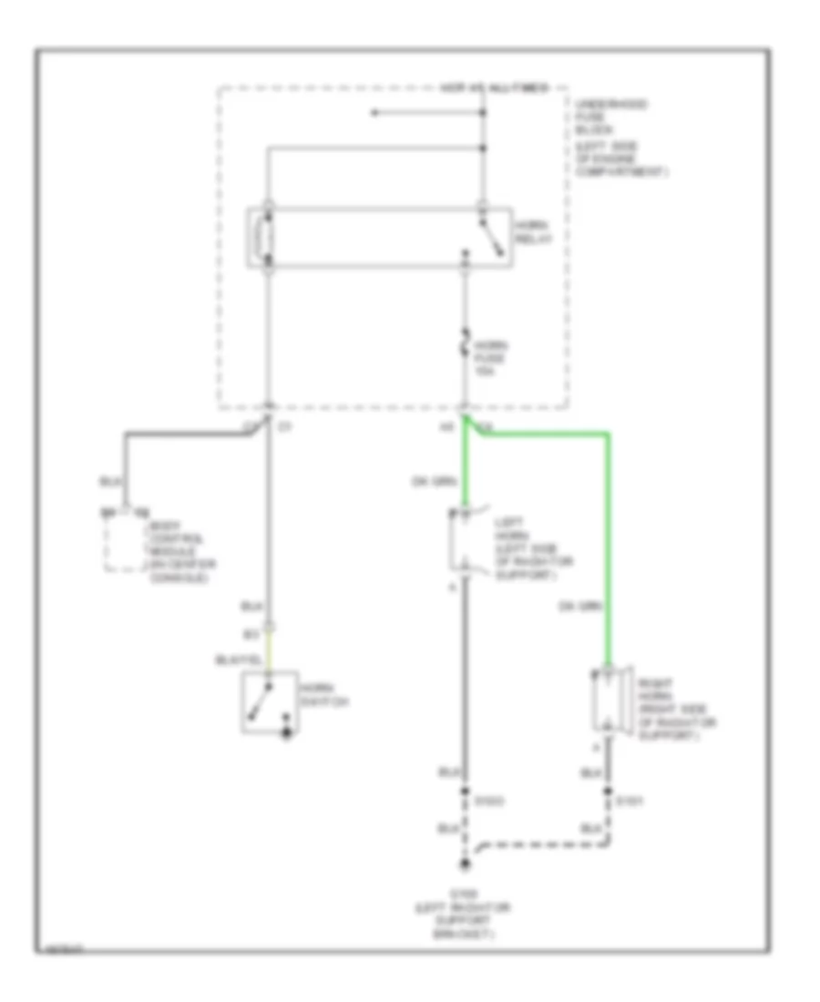
Horn Wiring Diagram for GMC Cab & Chassis Sierra 2004 3500
List of elements for Horn Wiring Diagram for GMC Cab & Chassis Sierra 2004 3500:
- (left side of engine compartment)
- C2 body control module (in center console)
- G100 (left radiator support bracket)
- Horn fuse 15a
- Horn relay
- Horn switch
- Hot at all times
- Left horn (left side of radiator support)
- Right horn (right side of radiator support)
- S101
- S10o
- Underhood fuse block
INSTRUMENT CLUSTER
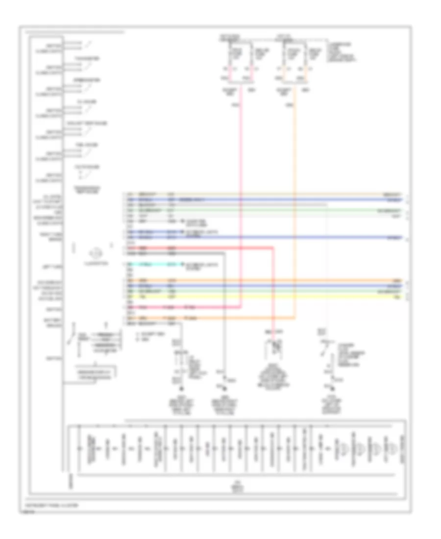
Instrument Cluster Wiring Diagram (1 of 2) for GMC Cab & Chassis Sierra 2004 3500
List of elements for Instrument Cluster Wiring Diagram (1 of 2) for GMC Cab & Chassis Sierra 2004 3500:
- (diesel only)
- A10
- A11
- A12
- Abs ind
- Air bag ind
- B10
- B11
- B12
- Battery
- Battery ind
- Body control module (bcm) (on lower left side of dash, below steering column)
- Brake
- Brake ind
- C1 lamp
- Cargo lamp ind
- Class 2 data
- Computer data lines
- Coolant temp gauge
- Cruise ind
- Dic fuel sig
- Dic mode sw
- Dic sw sig
- Dic toggle sw
- Eng speed sig
- Except seo
- Exterior lights system
- Fuel gauge
- G100 (on lower left of radiator support)
- G200 (behind right side of dash, near right "a" pillar)
- G203 (behind left side of dash, near left "a" pillar)
- Ground
- High beam ind
- Hot at all times
- Hot in run or start
- Hour meter
- I/p dim
- I/p relay block (near left kick panel)
- Ign e fuse 10a
- Ignition
- Illumination
- Instrument panel cluster
- Ipc serial data
- Ipc/dic fuse 10a
- Left turn
- Left turn ind
- Lo wash fluid
- Low fuel ind
- Message display
- Mil cntrl
- Odometer
- Oil gauge
- Orn
- Overdrive off ind
- Pnk
- Prnd321
- Red
- Right turn
- Right turn ind
- S100
- S202
- Seat belt ind
- Security ind
- Seo
- Seo b1 fuse 15a
- Seo ign fuse 10a
- Service 4wd ind
- Soon ind (mil) service engine
- Speedometer
- Tachometer
- Tire pressure ind
- Tow/haul ind
- Traction control ind
- Transmission temp gauge
- Trip
- Trip reset
- Underhood fuse block (left side of engine compt)
- Upshift ind
- Variable dimming
- Volts gauge
- Vss
- Wait to start
- Wait to start ind (diesel only)
- Washer fluid level sensor (in washer fluid reservoir)
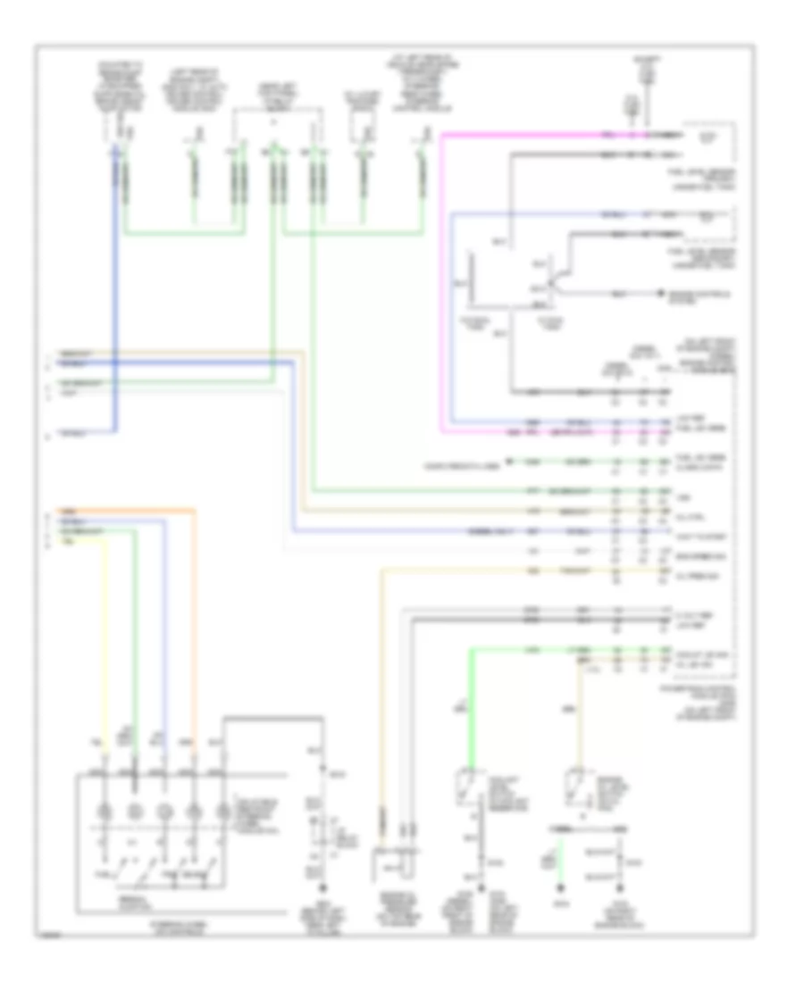
Instrument Cluster Wiring Diagram (2 of 2) for GMC Cab & Chassis Sierra 2004 3500
List of elements for Instrument Cluster Wiring Diagram (2 of 2) for GMC Cab & Chassis Sierra 2004 3500:
- (at left rear of vehicle, near spare tire bracket) (w/ 4 wheel steering) rear wheel steering control module
- (diesel only)
- (left rear of engine compt) (gas only, w/ auto cruise control) cruise control module (ccm)
- (near left kick panel) i/p relay block
- (on left front of engine compt) (diesel) engine control module (ecm)
- (w/ luxury package) radio
- 5 volt ref
- 5.3l flex fuel
- A10
- Class 2 data
- Computer data lines
- Coolant level switch (in coolant reservoir)
- Coolnt lev sig
- Diesel
- Diesel (6.6 vin 1)
- Diesel (6.6 vin 2)
- Eng speed sig
- Engine controls system
- Engine oil level switch (on oil pan)
- Engine oil pressure sensor (on top rear of engine)
- Except 5.3l flex fuel
- Fuel
- Fuel lev sens
- Fuel level sensor (primary) (inside fuel tank)
- Fuel level sensor (secondary) (inside fuel tank)
- G103 (on right rear of engine block)
- G104 (gas) (on left rear of engine block)
- G106 (diesel) (on right front of engine block)
- G108
- G203 (behind left side of dash, near left "a" pillar)
- Gas
- I/p relay block
- Inflatable restraint steering wheel module coil
- Low ref
- Mil ctrl
- Nca
- Oil lev sw
- Oil pres sig
- Person- alization
- Powertrain control module (pcm) (gas) (on left front of engine compt)
- S102
- S103
- S216
- S312
- Select
- Steering wheel dic controls
- Trip
- Vss
- W/ dual tank
- W/o dual tank
- Wait to start
INTERIOR LIGHTS
Courtesy Lamps Wiring Diagram (1 of 3) for GMC Cab & Chassis Sierra 2004 3500
List of elements for Courtesy Lamps Wiring Diagram (1 of 3) for GMC Cab & Chassis Sierra 2004 3500:
- A11
- B12
- Body control module (lower left side of dash, below steering column)
- C3 a6
- Cargo lamp low ctrl
- Class 2 data
- Class 2 serial data
- Convenience package comfort and decor level #3
- Crew cab only
- Crew cab w/ ye9
- Ctsy lamp ctrl
- Ctsy lamp on sig
- Ctsy lamp power
- Dome lamp switch
- Door ajar sig
- Driver door latch assembly
- Driver door module (ddm) (in left front door)
- F tan
- G305 (left "b" pillar)
- G306 (on right "b" pillar)
- Headlamp switch
- Int lamp defeat sig
- Int lamp defeat sw
- Left front door courtesy lamp
- Left rear door courtesy lamp (2003)
- Left rear door latch assembly
- Lf door ajar sig
- Low ref
- Lr door ajar sig
- Merchandised package luxury edition
- Rear dome lamp
- Rf door ajar sig
- Right rear door courtesy lamp (2003)
- Right rear door latch assembly
- Rr door ajar sig
- Sp205 (left side of dash)
- Tan
- W/ ye9 or w/ y91
- W/o ye9
- Y91 =
- Ye9 =
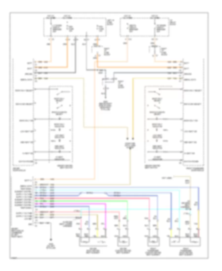
Courtesy Lamps Wiring Diagram (2 of 3) for GMC Cab & Chassis Sierra 2004 3500
List of elements for Courtesy Lamps Wiring Diagram (2 of 3) for GMC Cab & Chassis Sierra 2004 3500:
- (in headliner harness between overhead console reading lamps and i/p
- Cargo lamp
- Convenience package comfort and decor level 3
- Crew cab w/ ye9
- Dome
- Except crew cab w/ ye9
- Left vanity mirror lamp
- Map lamps
- Merchandised package luxury edition
- Overhead console
- Reading
- Rear courtesy reading lamps (crew cab w/ ye9)
- Relay block)
- Right vanity mirror lamp
- S321
- S345
- Tan
- W/ y91 and crew cab w/ ye9
- W/ ye9 and crew cab w/o ye9
- W/ ye9 except crew cab
- Y91 =
- Ye9 =
Courtesy Lamps Wiring Diagram (3 of 3) for GMC Cab & Chassis Sierra 2004 3500
List of elements for Courtesy Lamps Wiring Diagram (3 of 3) for GMC Cab & Chassis Sierra 2004 3500:
- (2003)
- A12
- B10
- Bin lamp
- C10
- C11
- Cargo lamp switch
- Class 2 data
- Convenience package comfort and decor level #3
- Ctsy lamp control
- Ctsy lamp power
- Door ajar sig
- Front passenger door courtesy light
- Front passenger door latch assembly
- Front passenger door module (fpdm) (in right front door)
- G200 (behind right side of dash, near right "a" pillar)
- G203 (near left "a" pillar)
- I/p compartment lamp
- I/p relay block (below left side of dash, left of steering column)
- Left i/p courtesy lamp
- Left i/p fuse block (under left side of dash)
- Low ref
- Merchandised package luxury edition
- Right i/p courtesy lamp (2003)
- Right i/p fuse block (lower right side of dash)
- S202
- S205
- S213
- Tan
- W/ ye9 or w/ y91
- W/o ye9
- Y91 =
- Ye9 =
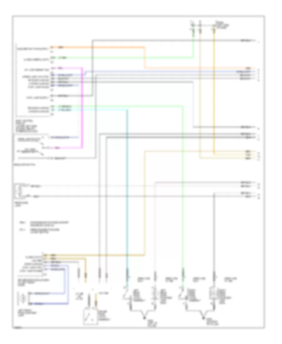
Instrument Illumination Wiring Diagram (1 of 3) for GMC Cab & Chassis Sierra 2004 3500
List of elements for Instrument Illumination Wiring Diagram (1 of 3) for GMC Cab & Chassis Sierra 2004 3500:
- 2 hi ind
- 2 hi ind control
- 4 hi ind
- 4 hi ind control
- 4 lo ind
- 4 lo ind control
- 5 volt ref
- A11
- A12
- Auto 4wd ind
- B pnk
- B11
- Body control module (lower left side of dash, below steering column)
- Crew cab only
- Diff lock ind control
- Dimming input
- Dimming return
- Drl off
- Drl off ind ctrl
- Fog lamp rly ctrl
- G305 (left "b" pillar)
- G306 (right "b" pillar)
- Headlamp on
- Headlamp on ind ctrl
- Headlamp switch
- Instrument panel cluster
- Instrument panel dimming
- Left rear window switch
- Np1 = transfer case, electric shift control, 2 speed np8 = transfer case active, 2 speed pushbutton control
- Pnk
- Red
- Right rear window switch
- S212
- Transfer case shift control module (behind headlamp switch)
- Transfer case shift control switch
- W/ np1
- W/ np8
Instrument Illumination Wiring Diagram (2 of 3) for GMC Cab & Chassis Sierra 2004 3500
List of elements for Instrument Illumination Wiring Diagram (2 of 3) for GMC Cab & Chassis Sierra 2004 3500:
- (left rear of vehicle, near spare tire bracket)
- (near left "a" pillar)
- 2ws ind
- 2ws ind control
- 4ws ind
- 4ws ind control
- Control
- Fog lamp circuit
- G203
- Hvac control module
- Inflatable restraint i/p module disable switch
- Inflatable restraint steering wheel module coil
- Lower left
- Lower right
- Multifunction accessory switch
- Nca
- Overhead console
- Power take off (pto) switch
- Rear wheel steering control module
- Rear wheel steering mode select switch
- Remote playback device-cd player
- S205
- Steering wheel
- Tan
- Tow ind
- Tow mode ind
- Traction control switch
- Transfer case shift control switch
- Underhood fuse block (left side of engine compt, near battery)
- Upper left
- Upper right
Instrument Illumination Wiring Diagram (3 of 3) for GMC Cab & Chassis Sierra 2004 3500
List of elements for Instrument Illumination Wiring Diagram (3 of 3) for GMC Cab & Chassis Sierra 2004 3500:
- (lower left side of dash)
- A11
- C10
- Driver window/door lock switch
- Electronic suspension system
- Exterior lamps
- Firm indicator
- Fog lamp
- Front passenger window/door lock switch
- G100 (lower left side of radiator core support)
- G200 (behind right side of dash, near right "a" pillar)
- G203 (near left "a" pillar)
- Headlamp leveling switch
- I/p relay block (below left side of dash, left of steering column)
- Left i/p fuse block
- Multifunction accessory switch
- Right i/p fuse block (lower left side of dash)
- Roof beacon switch
- S101
- S202
- S345
- Selectable ride switch
- W/ t89
- W/ t96
MEMORY SYSTEMS
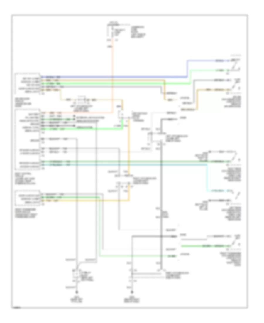
Memory Mirrors Wiring Diagram for GMC Cab & Chassis Sierra 2004 3500
List of elements for Memory Mirrors Wiring Diagram for GMC Cab & Chassis Sierra 2004 3500:
- 5 volt ref
- Batt (+)
- Battery
- Class 2 serial data
- Computer data lines system
- Ddm fuse 15a
- Driver door module (in driver's door)
- Driver outside rearview mirror
- Electro- chromic
- Exit
- Folding/ telescoping motor
- Front passenger door module (in passenger's door)
- Front passenger outside rearview mirror
- G200 (near right "a" pillar)
- Ground
- Heating element
- Horizontal
- Hot at all times
- I/p relay block (below left side of dash, left of steering column)
- Left
- Left i/p fuse block (lower left side of dash)
- Low ref
- Lt doors circuit breaker 25a
- Mem 1 sw sig
- Mem 2 sw sig
- Memory/ heated seat switch
- Mir htr low ref
- Mir htr sply voltage
- Mir mtr dwn ctrl
- Mir mtr extend ctrl
- Mir mtr retract ctrl
- Mir mtr rt ctrl
- Mir position sens sig
- Mir sens low ref
- Mir signal
- Mtr position sens sig
- Pdm fuse 15a
- Pnk
- Red
- Right i/p fuse block (lower right side of dash)
- Rt door circuit breaker 25a
- Rt/dwn mtr common
- S202 (in i/p harness)
- Set
- Tan
- Vert posit sens sig
- Vertical
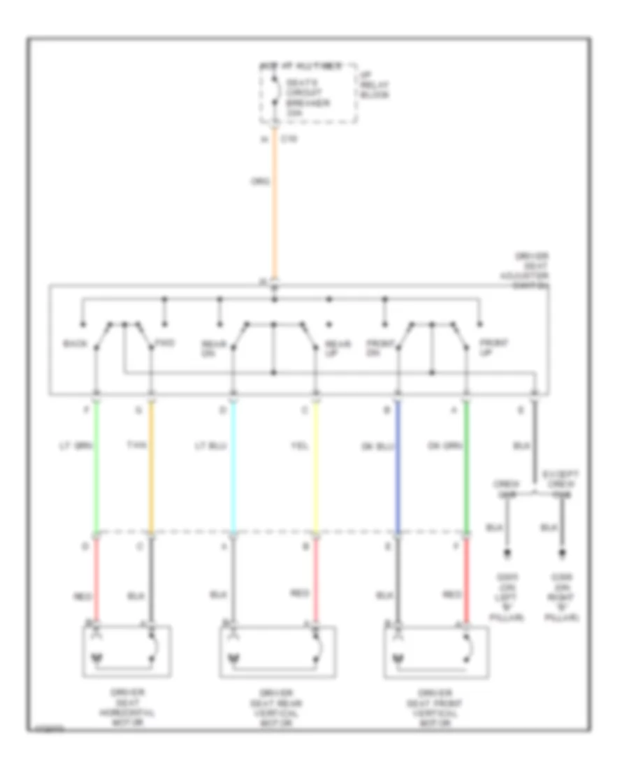
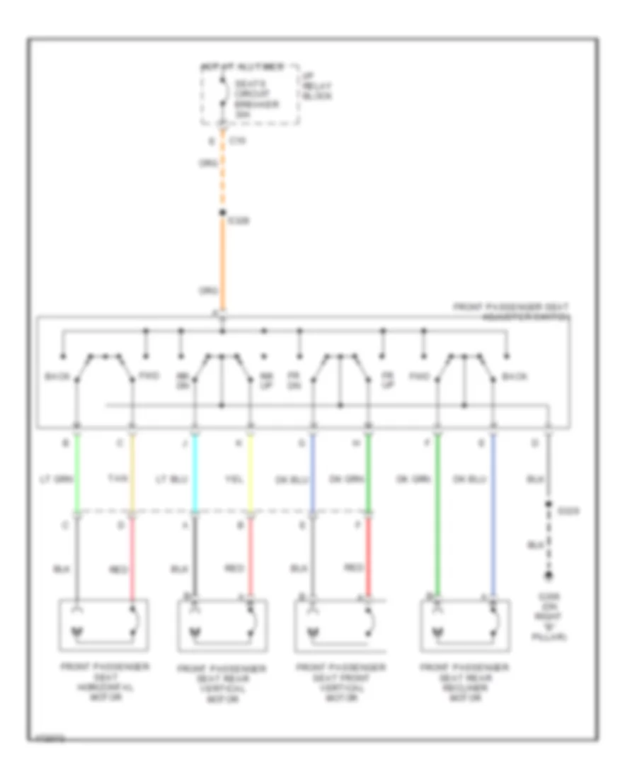
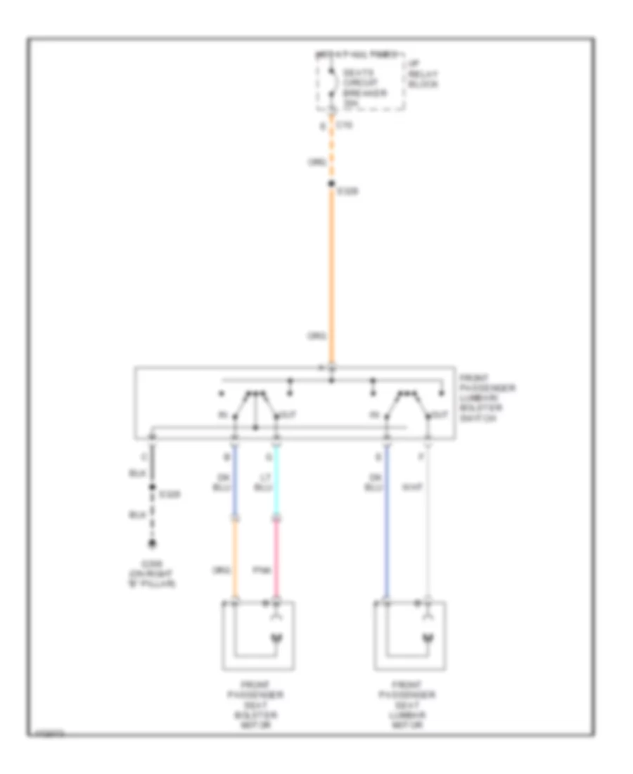
Memory Seat Wiring Diagram (1 of 2) for GMC Cab & Chassis Sierra 2004 3500
List of elements for Memory Seat Wiring Diagram (1 of 2) for GMC Cab & Chassis Sierra 2004 3500:
- (in driver seat harn)
- (not used)
- 5 volt ref
- Batt (+)
- C (not used)
- C10 h
- Class 2 serial data
- Computer data lines system
- Driver seat adjuster switch
- Frt dwn
- Frt up
- Frt vert dn sw sig
- Frt vert mtr dn ctrl
- Frt vert mtr pos sen
- Frt vert mtr up ctrl
- Frt vert up sw sig
- Fwd
- G305 (on left "b" pillar)
- Gnd
- Heated seat cus pwr
- Heated seat temp sig
- Horiz fwd sw sig
- Horiz mtr fwd ctrl
- Horiz mtr pos sen sig
- Horiz mtr rwd ctrl
- Horiz rwd sw sig
- Hot at all times
- Htd seat back ctrl
- Htd seat back pwr
- Htd seat cus ctrl
- Htd seat cus pwr
- I/p relay block (near left kick panel)
- Low ref
- Lum horiz pos sen sig
- Lum mtr fwd ctrl
- Lum mtr rwd ctrl
- Lum mtr rwd ctrl lum mtr rwd ctrl
- Memory seat module (under left front seat)
- Pnk
- Pnk pnk
- Rear vert dn sw sig
- Rear vert mtr pos sens
- Rear vert up sw sig
- Rec fwd
- Rec rwd
- Recline fwd sw sig
- Recline mtr fwd ctrl
- Recline mtr pos sen sig
- Recline mtr rwd ctrl
- Recline rwd sw sig
- Rr dwn
- Rr up
- Rr vert mtr dn ctrl
- Rr vert mtr up ctrl
- Rwd
- S311
- S314
- S315 (in driver seat harn)
- Seat circuit breaker 30a
- Seats system (heated seats circuit)
- Tan
- Torso blstr in sw sig
- Torso blstr out sw sig
- Torso bolster in ctrl
- Torso bolster out ctrl
- Trso blstr pos sens sig
Memory Seat Wiring Diagram (2 of 2) for GMC Cab & Chassis Sierra 2004 3500
List of elements for Memory Seat Wiring Diagram (2 of 2) for GMC Cab & Chassis Sierra 2004 3500:
- (in driver seat harn) s309
- (in driver seat harn) s310
- A red
- Batt (+)
- C (not used)
- Class 2 serial data
- Computer data lines system
- Driver door module (in driver's door)
- Driver seat bolster motor
- Driver seat bolster motor position sensor
- Driver seat bolster/ lumbar switch
- Driver seat front vertical motor
- Driver seat front vertical position sensor
- Driver seat horiz- ontal position sensor
- Driver seat lumbar motor
- Driver seat lumbar motor position sensor
- Driver seat rear vertical motor
- Driver seat rear vertical position sensor
- Driver seat recliner motor
- Driver seat recliner motor position sensor
- Exit
- Mem 1 sw sig
- Mem 2 sw sig
- Memory/ heated seat switch
- Out
- Pnk
- Red
- Set
- Tan
POWER DISTRIBUTION
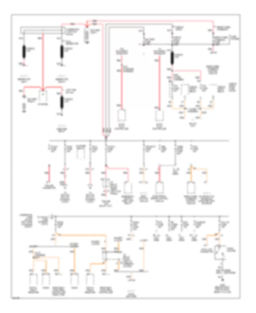
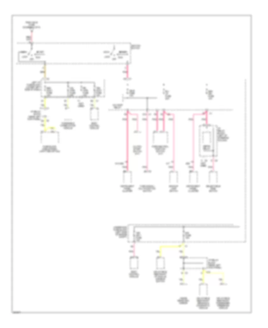
6.6L VIN 2
6.6L VIN 2, Power Distribution Wiring Diagram (1 of 5) for GMC Cab & Chassis Sierra 2004 3500
List of elements for 6.6L VIN 2, Power Distribution Wiring Diagram (1 of 5) for GMC Cab & Chassis Sierra 2004 3500:
- (base) (exc base)
- (in seo harness)
- (not used)
- 4ws fuse 15a
- A c7
- A12
- Abs fuse 60a
- Audio amplifier
- B c9
- B11 c1
- B12 c1
- B2 c3
- Battery (left)
- Battery (right)
- Battery fuse 175a
- Body control module
- C3 b
- C7 b
- C9 d
- Cig ltr fuse 15a
- Cigar lighter
- D12 c1
- Data link connector
- Digital radio receiver
- Dual generator
- E10
- Eap fuse 15a
- Electronic brake control module
- Emergency vehicle roof lamp relay
- Evaporative emissions canister vent solenoid
- Except luxury
- F2 c1
- Fuse holder
- Fusible link
- G200 (behind right side of dash, near "a" pillar)
- Generator (left)
- Generator (right)
- Glow plug controller
- Harness)
- I/p relay block (left of steering column)
- I/p relay block (near left kick panel)
- Ign a fuse 40a
- Ign b fuse 40a
- Luxury
- Mini fuse 30a
- Mobile radio
- Mobile radio fuse 125a
- Mobile radio fuse block
- Mobile radio relay
- Nca
- Radio
- Radio amp fuse 30a
- Radio fuse 15a
- Rear seat audio (rsa) controller
- Rear seat audio (rsa) controller (crew cab)
- Rear wheel steering
- Rear wheel steering control module
- Rear wheel steering fuse 125a
- Red
- Rr wiper fuse 25a
- Rtd fuse 30a
- S127 (in engine harness)
- S205 s303
- S220 (in seo red
- S221
- S222
- Starter
- Starter relay
- Stud 1 fuse 40a
- Stud 2 fuse 30a
- Sunroof fuse 25a
- Tbc batt fuse 10a
- To ignition switch (diagram 4 of 5)
- To ignition switch (diagram 5 of 5)
- To ipc/dic fuse (diagram 2 of 5)
- Trailer connector
- Underhood fuse block (left side of engine compt)
- Underhood junction block
- Upfitter option
- Vses/ ecas fuse 60a
- W/ california emissions
- W/o california emissions
- Wrecker relay
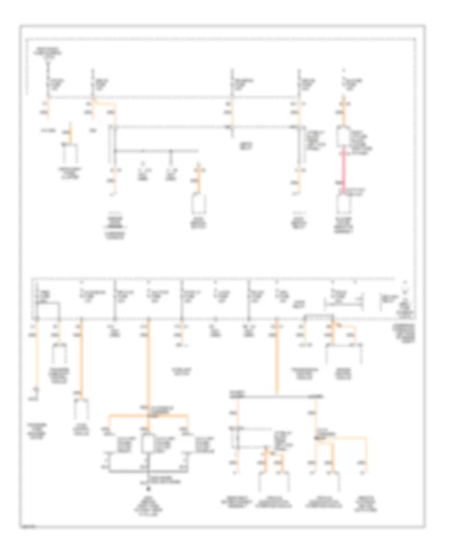
6.6L VIN 2, Power Distribution Wiring Diagram (2 of 5) for GMC Cab & Chassis Sierra 2004 3500
List of elements for 6.6L VIN 2, Power Distribution Wiring Diagram (2 of 5) for GMC Cab & Chassis Sierra 2004 3500:
- (auto a/c) (man a/c)
- (in i/p harness) s335
- (not used)
- 8s8
- A c10
- A g
- A10
- Aux pwr fuse 20a
- Auxiliary power outlet (bin)
- Auxiliary power outlet (console)
- Auxiliary power outlet (front)
- B c5
- B11
- B11 c1
- Blower fuse 40a
- Blower motor resistor assembly
- C1 c2
- C1 f12
- C10
- C3 b
- C4 d
- C4 e6
- C6 a
- C8 a
- D12
- Defog relay
- E c8
- E11 c1
- Edu/ign1 relay
- Engine control module
- Except luxury
- F/pmp relay
- From radio fuse (diagram 1 of 5)
- G200 (behind right side of dash, near "a" pillar)
- Garage door opener
- Hvac control module
- Hvac/ecas fuse 10a
- I/p relay block (near left kick panel)
- Info fuse 15a
- Instrument panel cluster
- Ipc/dic fuse 10a
- Lh hid fuse 20a
- Luxury
- Nca
- Overhead console
- Pcm b fuse 20a
- Rear seat entertainment assembly
- Red
- Remote playback device (cd player)
- Rh hid fuse 20a
- Right i/p fuse block (lower right side of dash)
- Roof beacon relay
- Roof beacon switch
- Rr defog fuse 30a
- Rr hvac fuse 30a
- Seo b1 fuse 15a
- Seo b2 fuse 30a
- Stop lp fuse 25a
- Stoplamp switch
- To lbec 1 fuse (diagram 3 of 5)
- Transfer case encoder motor
- Transfer case shift control module
- Transmission control module
- Trec fuse 30a
- Underhood fuse block (left side of engine compt)
- Vehicle communication interface module
- W/o 8s8
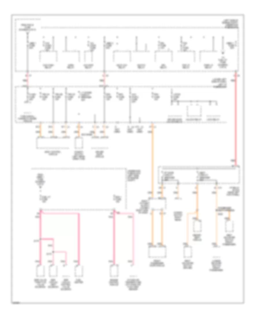
6.6L VIN 2, Power Distribution Wiring Diagram (3 of 5) for GMC Cab & Chassis Sierra 2004 3500
List of elements for 6.6L VIN 2, Power Distribution Wiring Diagram (3 of 5) for GMC Cab & Chassis Sierra 2004 3500:
- (left side of engine compt) underhood fuse block
- (lower left side of dash)
- (not used)
- (passenger seat harness)
- A c5
- A c6
- A/c comp fuse 10a
- A/c comp relay
- A10 c1
- A12
- A7 c1
- Aux pwr 2 fuse 20a
- B c7
- B12
- Body control module
- C c3
- C9 c1
- Ddm fuse 15a
- Driver door module
- Driver door unlock relay
- Drl fuse 10a
- Drl relay
- E c10
- E c7
- E10
- E11 c1
- E12
- Ecc fuse 10a
- Ecm 1 fuse 15a
- Egr vacuum control valve solenoid
- Egr vacuum vent solenoid
- Egr valve throttle valve solenoid
- Engine control module
- Exc base
- F c3
- Flash fuse 25a
- Fog lp fuse 15a
- Fog lp relay
- From mbec 1 fuse (diagram 3 of 5)
- From pcm b fuse (diagram 2 of 5)
- Front passenger door module
- Fuel heater
- Fuel ht fuse 15a
- G c4
- Hdlp-hi relay
- Hdlp-low relay
- Horn relay
- I/p relay block (near left kick panel)
- Intake air temperature (iat)/mass air flow (maf) sensor
- Lbec 1 fuse 50a
- Lbec 2 fuse 50a
- Left i/p fuse block
- Lock relay
- Locks fuse 20a
- Lt doors circuit breaker 25a
- Lumbar bolster switch (front passenger)
- M c4
- Mbec 1 fuse 50a
- Memory seat module
- Park lp relay
- Pdm fuse 10a
- Pnk
- Red
- Right i/p fuse block (lower right side of dash)
- Rt door circuit breaker 25a
- S178
- S179
- S328
- Seat adjuster switch (driver)
- Seat adjuster switch (front passenger)
- Seat circuit breaker 30a
- Tbc 2a fuse 15a
- Tbc 2b fuse 15a
- Tbc 2c fuse 15a
- To fuel ht fuse (diagram 3 of 5)
- Turn signal/ hazard flasher module
- Underhood fuse block (left side of engine compt)
- Unlock relay
- W/s wash fuse 15a
- W/s wash relay
- Window switch (left rear) (crew cab)
- Window switch (right rear)
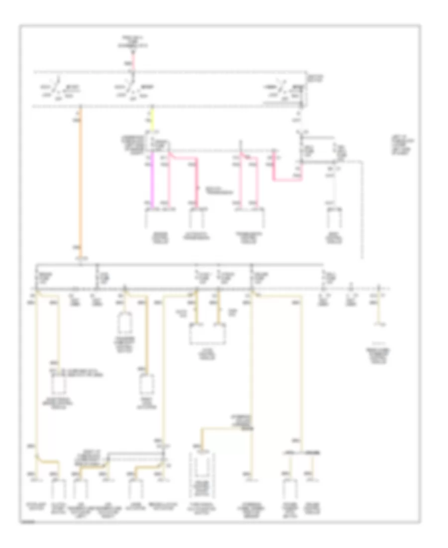
6.6L VIN 2, Power Distribution Wiring Diagram (4 of 5) for GMC Cab & Chassis Sierra 2004 3500
List of elements for 6.6L VIN 2, Power Distribution Wiring Diagram (4 of 5) for GMC Cab & Chassis Sierra 2004 3500:
- (auto a/c)
- (man a/c)
- (not used)
- (over 8600 gvw) (8600 gvw or less)
- (steering column harness) s240
- 4wd fuse 15a
- Acc
- Air temperature actuator (left)
- Air temperature actuator (right)
- Automatic transmission
- B10 a1
- Body control module
- Brake fuse 10a
- C1 c9
- C1 d12
- C1 e8
- C175
- C2 c2
- C4 b
- C4 c
- Clutch start switch
- Crank fuse 10a
- Cruise
- Cruise control module
- Cruise control on/off switch
- Cruise fuse 10a
- E11
- Electronic brake control module
- Engine control module
- Exc m74 transmission
- F10
- From ign a fuse (diagram 1 of 5)
- Front axle actuator
- Htr/ac fuse 30a
- Hvac 1 fuse 10a
- Hvac control module
- Ign 0 fuse 10a
- Ign 3 fuse 10a
- Ignition switch
- Left i/p fuse block (lower left side of dash)
- Lock
- Mode actuator
- Off
- Pnk
- Power takeoff (pto) switch
- Pto
- Rear wheel steering control module
- Recirculation actuator
- Red
- Right i/p fuse block (lower right side of dash)
- Run
- Start
- Steering wheel speed/ position sensor
- Stoplamp switch
- Tbc ign 0 fuse 10a
- Transfer case shift control switch
- Transmission control module
- Turn signal multifunction switch
- Underhood fuse block (left side of engine compt)
6.6L VIN 2, Power Distribution Wiring Diagram (5 of 5) for GMC Cab & Chassis Sierra 2004 3500
List of elements for 6.6L VIN 2, Power Distribution Wiring Diagram (5 of 5) for GMC Cab & Chassis Sierra 2004 3500:
- (not used)
- 8s8
- A/c comp relay
- Acc
- B/u lp fuse 20a
- Backup lamp switch
- Body control module
- C c8
- C1 b2
- C10
- C8 d8
- Clutch start switch (m/t)
- D c5
- D10 c1
- Defog relay
- E c3
- F11
- From ign b fuse (diagram 1 of 5)
- Fuse block mobile radio (upfitter option)
- I/p relay block (left of steering column)
- I/p relay block (near left kick panel)
- Ign e fuse 10a
- Ignition switch
- Inflatable restraint i/p module disable switch
- Inflatable restraint passenger presence module
- Inflatable restraint sensing & diagnostic module
- Inside rearview mirror
- Instrument panel cluster
- Left i/p fuse block (lower left side of dash)
- Lock
- M/t
- Off
- Park/neutral position switch (a/t)
- Pnk
- Rr wpr fuse 15a
- Run
- Selectable ride switch
- Seo accy fuse 10a
- Seo ign fuse 10a
- Sir fuse 15a
- Start
- Tbc accy fuse 10a
- Tbc ign 1 fuse 10a
- Turn signal/ multifunction switch
- Underhood fuse block (left side of engine compt)
- W/o 8s8
- Windshield wiper motor module
- Ws wpr fuse 25a
POWER DOOR LOCKS
Power Door Locks Wiring Diagram, Base for GMC Cab & Chassis Sierra 2004 3500
List of elements for Power Door Locks Wiring Diagram, Base for GMC Cab & Chassis Sierra 2004 3500:
- (gasoline) (diesel)
- A12
- B10
- B11
- B12
- Battery
- Body control module (on lower left side of dash, near steering column)
- C1 2c
- C1 c9
- C1 d10
- C1 d11
- C1 d12
- C1 f6
- C3 b
- C3 f
- C7 f
- Driver door lock actuator
- Driver door lock switch
- Driver unlock relay
- Front passenger door lock actuator
- Front passenger door lock switch
- G200 (below right side of dash)
- G203 (near left "a" pillar)
- Hot at all times
- I/p relay block (near left kick panel)
- Ign key sw
- Ignition key alarm switch (on ignition key cylinder)
- Instrument panel cluster
- Left i/p fuse block (lower left side of dash)
- Left rear door lock actuator
- Lock
- Lock ctrl
- Lock relay
- Locks fuse 20a
- Pcm ecm (left front of engine compartment)
- Relay ctrl
- Right i/p fuse block (lower right side of dash)
- Right rear door lock actuator
- S202 (in i/p harn)
- S217
- Serial data
- Splice pack sp205 (in i/p harn)
- Tan
- Tbc batt fuse 10a
- Underhood fuse block (on left side of engine compt)
- Unlock
- Unlock ctrl
- Unlock relay
- W/ crew cab
Power Door Locks Wiring Diagram, Up Level (1 of 2) for GMC Cab & Chassis Sierra 2004 3500
List of elements for Power Door Locks Wiring Diagram, Up Level (1 of 2) for GMC Cab & Chassis Sierra 2004 3500:
- (gasoline) (diesel)
- (lower left side of dash) left i/p fuse block
- A12
- B12
- Battery
- Body control module (on lower left side of dash, near steering column)
- C1 a2
- C1 a7
- C1 f6
- C4 l (not used)
- Door lock switch
- Driver door module (inside driver door)
- F (not used)
- Front passenger door module (inside right front passenger door)
- G200 (behind right side of dash)
- G200 (below right side of dash)
- G203 (near left kick panel)
- Ground
- Hot at all times
- I/p relay block (behind left side of dash)
- Ign key sw
- Ignition key alarm switch (on ignition key cylinder)
- Key sw
- Key sw sig
- Left i/p fuse block (lower left side of dash)
- Left rear door lock actuator
- Lock
- Lock ctrl
- Lock relay
- Locks fuse 20a
- Pcm ecm (left front of engine compartment)
- Pdm fuse 10a
- Right i/p fuse block (behind right side of dash)
- Right i/p fuse block (lower right side of dash)
- Right rear door lock actuator
- S202 (in i/p harn)
- S217
- Serial data
- Tan
- Unlock
- Unlock ctrl
- Unlock relay
Power Door Locks Wiring Diagram, Up Level (2 of 2) for GMC Cab & Chassis Sierra 2004 3500
List of elements for Power Door Locks Wiring Diagram, Up Level (2 of 2) for GMC Cab & Chassis Sierra 2004 3500:
- (lower right side of dash) right i/p fuse block
- C1 d12
- Driver mini wedge door jamb switch (rear of driver's door)
- Front passenger mini wedge door jamb switch (rear of left front passenger's door)
- Hot at all times
- Instrument panel cluster
- Key sw
- Lock act
- Splice pack sp205 (in i/p harn)
- Tan
- Tbc batt fuse 10a
- Underhood fuse block (on left side of engine compt)
POWER MIRRORS
Electrochromic Mirror Wiring Diagram for GMC Cab & Chassis Sierra 2004 3500
List of elements for Electrochromic Mirror Wiring Diagram for GMC Cab & Chassis Sierra 2004 3500:
- A12
- A7 c1
- Air temp sensor
- Ambient photo sensor
- B11
- B12
- Back up lamp voltage output c5
- Back up voltage
- Body control module (bcm) (on lower left side of dash, below steering column)
- Body relay block
- Compass
- Computer data lines system
- Driver door module (ddm) (in driver's door)
- Driver outside rearview mirror
- Electrochromic mirror
- G200 (near right "a" pillar)
- Ground
- Hot in run & start
- Ign 1
- Inside rearview mirror
- Left i/p fuse block (lower left side of dash)
- Low ref
- Mir signal
- Nca
- On/off
- Outside air temperature sensor
- Pnk
- Rr light photo sensor
- S345
- Selector switch
- Serial data
- Sir fuse 15a
- Temp
- Underhood fuse block (left side of engine compt)
Power Mirrors Wiring Diagram for GMC Cab & Chassis Sierra 2004 3500
List of elements for Power Mirrors Wiring Diagram for GMC Cab & Chassis Sierra 2004 3500:
- 5 volt ref
- B11
- Battery
- Class 2 serial data
- Computer data lines system
- Ddm fuse 15a
- Down
- Driver door module (in driver's door)
- Driver mirror
- Driver outside rearview mirror
- Electro- chromic
- Folding/ telescoping motor
- Front passenger door module (in right front door)
- Front passenger outside rearview mirror
- G200 (near right "a" pillar)
- Ground
- Heating element
- Horizontal
- Hot at all times
- Hvac control module (in center of dash)
- I/p relay block (near left kick panel)
- Left
- Left i/p fuse block (lower left side of dash)
- Low ref
- Lt doors circuit breaker 25a
- Mir htr low ref
- Mir htr sply voltage
- Mir mtr dwn ctrl
- Mir mtr extend ctrl
- Mir mtr retract ctrl
- Mir mtr rt ctrl
- Mir position sens sig
- Mir sens low ref
- Mir signal
- Mtr position sens sig
- Pass- enger mirror
- Pdm fuse 10a
- Pnk
- Red
- Right
- Right i/p fuse block (lower right side of dash)
- Rt door circuit breaker 25a
- Rt/dwn mtr common
- S202
- Switch power
- Tan
- Vert posit sens sig
- Vertical
POWER SEATS
Driver Seat Wiring Diagram for GMC Cab & Chassis Sierra 2004 3500
List of elements for Driver Seat Wiring Diagram for GMC Cab & Chassis Sierra 2004 3500:
- Back
- C10
- Crew cab
- Driver seat adjuster switch
- Driver seat front vertical motor
- Driver seat horizontal motor
- Driver seat rear vertical motor
- Except crew cab
- Front dn
- Front up
- Fwd
- G305 (on left "b" pillar)
- G306 (on right "b" pillar)
- Hot at all times
- I/p relay block
- Rear dn
- Rear up
- Red
- Seats circuit breaker 30a
- Tan
Heated Seats Wiring Diagram for GMC Cab & Chassis Sierra 2004 3500
List of elements for Heated Seats Wiring Diagram for GMC Cab & Chassis Sierra 2004 3500:
- (in driver seat jumper harness)
- (in driver's seat harness) s311
- (not used)
- Back & cushion select
- Back only ind
- Back only indicator
- Back only select
- Batt
- Batt (+)
- Bck & csh select
- C1 4a
- C1 7e
- C1 a7
- C1 c9
- C1 f6
- C10 h
- C2 f
- C3 c
- C3 d
- C3 f
- C4 a
- C7 c
- C7 e
- Computer data lines system
- Ddm fuse 15a
- Driver back heated seat element
- Driver cushion heated seat element
- Driver door module
- Element control
- Front passenger back heated seat element
- Front passenger cushion heated seat element
- Front passenger door module
- G200 (behind right side of dash, near right "a" pillar)
- G305 (on left "b" pillar)
- Gnd
- Ground
- Hi heat ind
- Hi heat indicator
- Hot at all times
- I/p relay block
- Left i/p fuse block
- Low heat ind
- Low heat indicator
- Low ref
- Lt doors circuit breaker 25a
- Med heat ind
- Med heat indicator
- Memory seat module (underside of left front seat)
- Memory/heated seat switch
- Nca
- Pdm fuse 10a
- Pnk
- Right i/p fuse block
- Rt doors circuit breaker 30a
- S202
- S314
- Seats circuit breaker 30a
- Serial data
- Switch power
- Tan
- Temp signal
Passenger Full Feature Seat Wiring Diagram for GMC Cab & Chassis Sierra 2004 3500
List of elements for Passenger Full Feature Seat Wiring Diagram for GMC Cab & Chassis Sierra 2004 3500:
- Back
- C10
- Fr dn
- Fr up
- Front passenger seat adjuster switch
- Front passenger seat front vertical motor
- Front passenger seat horizontal motor
- Front passenger seat rear recliner motor
- Front passenger seat rear vertical motor
- Fwd
- G306 (on right "b" pillar)
- Hot at all times
- I/p relay block
- Red
- Rr dn
- Rr up
- S328
- S329
- Seats circuit breaker 30a
- Tan
Passenger"s Lumbar Wiring Diagram for GMC Cab & Chassis Sierra 2004 3500
List of elements for Passenger"s Lumbar Wiring Diagram for GMC Cab & Chassis Sierra 2004 3500:
- C10 e
- Front passenger lumbar/ bolster switch
- Front passenger seat bolster m0tor
- Front passenger seat lumbar m0tor
- G306 (on right "b" pillar)
- Hot at all times
- I/p relay block
- Out
- Pnk
- S328
- S329
- Seats circuit breaker 30a
POWER WINDOWS
Power Windows Wiring Diagram for GMC Cab & Chassis Sierra 2004 3500
List of elements for Power Windows Wiring Diagram for GMC Cab & Chassis Sierra 2004 3500:
- (crew cab)
- B+ volt
- B12
- Bcm class 2 serial data
- Body control module (left side of dash)
- Body relay block
- C1 7b
- C10
- C7 e
- Ddm class 2 serial data
- Driver door module
- Driver window motor
- Front passenger door module
- Front passenger window motor
- G305 (on left "b" pillar)
- G306 (on right "b" pillar)
- Ground
- Hot at all times
- Illumination
- Interior lights system
- Left front window
- Left i/p fuse block (left side of dash)
- Left rear window
- Left rear window motor
- Left window switch
- Logic
- Lt doors circuit breaker 25a
- Pwr wnd lockout lr sig
- Pwr wnd lockout lr signal
- Pwr wnd lockout rr sig
- Pwr wnd lockout rr signal
- Pwr wnd motor lf down cntrl
- Pwr wnd motor lf up cntrl
- Pwr wnd motor lr rear down cntrl
- Pwr wnd motor lr rear up cntrl
- Pwr wnd motor rf down cntrl
- Pwr wnd motor rf up cntrl
- Pwr wnd motor rr rear down cntrl
- Pwr wnd motor rr rear up cntrl
- Pwr wnd sw lr down sig
- Pwr wnd sw lr up sig
- Pwr wnd sw rr down sig
- Pwr wnd sw rr up sig
- Pwr wnd switch lr down signal
- Pwr wnd switch lr up signal
- Pwr wnd switch rr down signal
- Pwr wnd switch rr up signal
- Right i/p fuse block (right side of dash)
- Right rear window
- Right rear window motor
- Right window switch
- Rr window (crew cab)
- Rt doors circuit breaker 25a
- Splice pack sp205
- Switch power
- Tan
- Window down
- Window right front
- Window up
RADIO
Base Radio Wiring Diagram for GMC Cab & Chassis Sierra 2004 3500
List of elements for Base Radio Wiring Diagram for GMC Cab & Chassis Sierra 2004 3500:
- A10
- A11
- A12
- Antenna
- Aud out -
- B10
- B11
- B12
- Bare
- Cell voice sig
- Coax
- Common aud sig
- Computer data lines system
- Digital radio antenna
- Digital radio receiver (if equipped)
- Drain wire
- G203 (near left "a" pillar)
- Ground
- Hot at all times
- I/p relay block (near left kick panel)
- Left aud sig
- Left front door speaker
- Left front tweeter speaker
- Left i/p fuse block (on lower left side of dash)
- Left rear door speaker (except standard cab) left rear speaker (standard cab)
- Lf aud +
- Lf spk out+
- Lf spk out-
- Lr spk out +
- Lr spk out -
- Radio
- Radio fuse 15a
- Rf spk out +
- Rf spk out -
- Right aud sig
- Right front door speaker
- Right front tweeter speaker
- Right i/p fuse block (on lower right side of dash)
- Right rear door speaker (except standard cab) right rear speaker (standard cab)
- Rr spk out+
- Rr spk out-
- Rt aud +
- Serial data
- Tan
- Underhood fuse block (at left side of engine compartment)
- Vehicle communication interface module (behind passenger air bag module)
- Voice low ref
- Voice signal
Mid-Line Radio Wiring Diagram, with Rear Seat Audio (1 of 3) for GMC Cab & Chassis Sierra 2004 3500
List of elements for Mid-Line Radio Wiring Diagram, with Rear Seat Audio (1 of 3) for GMC Cab & Chassis Sierra 2004 3500:
- (i/p harness) sp205
- (in console harness) s330
- A10
- A11
- A12
- Antenna
- B10
- B11
- B12
- B31
- Bare
- Bcm class 2 serial data
- Body control module (below steering column)
- C201
- C277
- Cell voice sig
- Coax
- Common aud sig
- Computer data lines system
- Drain wire
- Enable sig
- Engine controls system
- G203 (near left "a" pillar)
- Ground
- Hot at all times
- I/p relay block (near left kick panel)
- Inflatable restraint steering wheel module coil
- Left aud sig
- Left steering wheel audio control switch
- Lf spk out+
- Lf spk out-
- Lr aud sig+
- Lr aud sig-
- Lr spk out +
- Lr spk out -
- Nca
- Pnk
- Prog
- Radio
- Radio fuse 15a
- Radio mute
- Radio on sig
- Rear seat audio controller (on rear of center console)
- Remote radio control signal
- Rf spk out +
- Rf spk out -
- Right aud sig
- Right steering wheel audio control switch
- Rr aud sig+
- Rr aud sig-
- Seek dn
- Seek up
- Serial data
- Source dn
- Source up
- Steering wheel
- Tan
- Underhood fuse block (at left side of engine compartment)
- Vehicle communication interface module
- Voice
- Voice low ref
- Voice signal
- Vol dn
- Vol up
- Vss signal
Mid-Line Radio Wiring Diagram, with Rear Seat Audio (2 of 3) for GMC Cab & Chassis Sierra 2004 3500
List of elements for Mid-Line Radio Wiring Diagram, with Rear Seat Audio (2 of 3) for GMC Cab & Chassis Sierra 2004 3500:
- A10
- A11
- A12
- Audio amplifier
- B10
- B11
- B12
- Bare
- Drain wire
- Ground
- Hot at all times
- I/p relay block (below lower left side of dash)
- L spk out+
- L spk out-
- Left front door speaker
- Left front tweeter speaker
- Left i/p fuse block (on lower left side of dash)
- Left rear door speaker (crew cab) left rear speaker (except crew cab)
- Left subwoofer
- Lf aud sig+
- Lf aud sig-
- Lf spkr out+
- Lf spkr out-
- Lr aud sig+
- Lr aud sig-
- Lr spkr out+
- Lr spkr out-
- Pnk
- R spk out+
- R spk out-
- Radio fuse 15a
- Radio mute
- Radio on sig
- Rf aud sig+
- Rf aud sig-
- Rf spkr out+
- Rf spkr out-
- Right front door speaker
- Right front tweeter speaker
- Right i/p fuse block (on lower right side a of dash)
- Right rear door speaker (crew cab) right rear speaker (except crew cab)
- Right subwoofer
- Rr aud sig+
- Rr aud sig-
- Rr spkr out+
- Rr spkr out-
- Rsa enable
- Subwoofer speaker
- Tan
- Underhood fuse block (at left side of engine compartment)
Mid-Line Radio Wiring Diagram, with Rear Seat Audio (3 of 3) for GMC Cab & Chassis Sierra 2004 3500
List of elements for Mid-Line Radio Wiring Diagram, with Rear Seat Audio (3 of 3) for GMC Cab & Chassis Sierra 2004 3500:
- Antenna
- Aud out -
- B11
- Bare
- Coax
- Com aud sig
- Computer data lines system
- Data lines
- Digital radio antenna
- Digital radio receiver (if equipped)
- Drain wire
- G203 (near left "a" pillar)
- Ground
- Hot at all times
- I/p relay block (near left kick panel)
- Info fuse 15a
- Lf aud +
- Lt aud sig
- Rear seat entertainment assembly (if equipped)
- Rt aud +
- Rt aud sig
- Serial data
- Splice pack sp250 (near hvac control module)
- Underhood fuse block (at left side of engine compartment)
Mid-Line Radio Wiring Diagram, without Rear Seat Audio (1 of 3) for GMC Cab & Chassis Sierra 2004 3500
List of elements for Mid-Line Radio Wiring Diagram, without Rear Seat Audio (1 of 3) for GMC Cab & Chassis Sierra 2004 3500:
- (i/p harness) sp205
- (in console harness)
- A10
- A11
- A12
- Antenna
- B10
- B11
- B12
- B31
- Bare
- Bcm class 2 serial data
- Body control module (below steering column)
- C201
- C277
- Cell voice sig
- Coax
- Common aud sig
- Computer data lines system
- Drain wire
- Enable sig
- Engine controls system
- G203 (near left "a" pillar)
- Ground
- Hot at all times
- I/p relay block (near left kick panel)
- Inflatable restraint steering wheel module coil
- Left aud sig
- Left steering wheel audio control switch
- Lf spk out +
- Lf spk out -
- Lr aud sig +
- Lr aud sig -
- Nca
- Pnk
- Prog
- Radio
- Radio fuse 15a
- Radio mute
- Radio on sig
- Remote radio control signal
- Rf spk out +
- Rf spk out -
- Right aud sig
- Right steering wheel audio control switch
- Rr aud sig +
- Rr aud sig -
- S330
- Seek dn
- Seek up
- Serial data
- Source dn
- Source up
- Steering wheel
- Tan
- Underhood fuse block (at left side of engine compartment)
- Vehicle communication interface module
- Voice
- Voice low ref
- Voice signal
- Vol dn
- Vol up
- Vss signal
Mid-Line Radio Wiring Diagram, without Rear Seat Audio (2 of 3) for GMC Cab & Chassis Sierra 2004 3500
List of elements for Mid-Line Radio Wiring Diagram, without Rear Seat Audio (2 of 3) for GMC Cab & Chassis Sierra 2004 3500:
- A10
- A11
- A12
- Audio amplifier
- B10
- B11
- B12
- Bare
- C1 b2
- Drain wire
- Ground
- Hot at all times
- I/p relay block (below lower left side of dash)
- L spk out+
- L spk out-
- Left front door speaker
- Left front tweeter speaker
- Left i/p fuse block (on lower left side of dash)
- Left rear speaker (crew cab) left rear door speaker (except crew cab)
- Left subwoofer
- Lf aud sig+
- Lf aud sig-
- Lf spkr out+
- Lf spkr out-
- Lr aud sig+
- Lr aud sig-
- Lr spkr out+
- Lr spkr out-
- Pnk
- R spk out+
- R spk out-
- Radio amp fuse 30a
- Radio fuse 15a
- Radio mute
- Radio on sig
- Rf aud sig+
- Rf aud sig-
- Rf spkr out+
- Rf spkr out-
- Right front door speaker
- Right front tweeter speaker
- Right i/p fuse block (on lower right side a of dash)
- Right rear speaker (crew cab) right rear door speaker (except crew cab)
- Right subwoofer
- Rr aud sig+
- Rr aud sig-
- Rr spkr out+
- Rr spkr out-
- Rsa enable
- Subwoofer speaker
- Tan
- Underhood fuse block (at left side of engine compartment)
Mid-Line Radio Wiring Diagram, without Rear Seat Audio (3 of 3) for GMC Cab & Chassis Sierra 2004 3500
List of elements for Mid-Line Radio Wiring Diagram, without Rear Seat Audio (3 of 3) for GMC Cab & Chassis Sierra 2004 3500:
- Antenna
- Aud out -
- B11
- Bare
- Coax
- Com aud sig
- Computer data lines system
- Data lines
- Digital radio antenna
- Digital radio receiver (if equipped)
- Drain wire
- G203 (near left "a" pillar)
- Ground
- Hot at all times
- I/p relay block (near left kick panel)
- Info fuse 15a
- Lf aud +
- Lt aud sig
- Nca
- Rear seat entertainment assembly (if equipped)
- Rt aud +
- Rt aud sig
- Serial data
- Splice pack sp250 (near hvac control module)
- Underhood fuse block (at left side of engine compartment)
Premium Sound Radio Wiring Diagram, with CD, with Rear Entertainment, with Digital Receiver (1 of 3) for GMC Cab & Chassis Sierra 2004 3500
List of elements for Premium Sound Radio Wiring Diagram, with CD, with Rear Entertainment, with Digital Receiver (1 of 3) for GMC Cab & Chassis Sierra 2004 3500:
- (i/p harness) sp205
- (in console harness)
- A10
- A11
- A12
- Antenna
- B10
- B11
- B12
- B31
- Bare
- Bcm class 2 serial data
- Body control module (below steering column)
- C201
- C277
- Cell voice sig
- Coax
- Common aud sig
- Computer data lines system
- Drain wire
- G203 (near left "a" pillar)
- Ground
- Hot at all times
- I/p relay block (near left kick panel)
- Inflatable restraint steering wheel module coil
- Left aud sig
- Left steering wheel audio control switch
- Lf aud sig+
- Lf aud sig-
- Lr aud sig +
- Lr aud sig -
- Lr aud sig+
- Lr aud sig-
- Nca
- Pnk
- Prog
- Radio
- Radio fuse 15a
- Rear seat audio controller (on rear of center console)
- Remote radio control signal
- Rf aud sig +
- Rf aud sig -
- Right aud sig
- Right steering wheel audio control switch
- Rr aud sig+
- Rr aud sig-
- S210
- S333
- Seek dn
- Seek up
- Serial data
- Source dn
- Source up
- Steering wheel
- Tan
- Underhood fuse block (at left side of engine compartment)
- Vehicle communication interface module (behind right side of dash)
- Voice
- Voice low ref
- Voice signal
- Vol dn
- Vol up
Premium Sound Radio Wiring Diagram, with CD, with Rear Entertainment, with Digital Receiver (2 of 3) for GMC Cab & Chassis Sierra 2004 3500
List of elements for Premium Sound Radio Wiring Diagram, with CD, with Rear Entertainment, with Digital Receiver (2 of 3) for GMC Cab & Chassis Sierra 2004 3500:
- A10
- A11
- A12
- Audio amplifier
- B10
- B11
- B12
- Bare
- Computer data lines system
- Drain wire
- Ground
- Hot at all times
- L spk out+
- L spk out-
- Left front door speaker
- Left front tweeter speaker
- Left i/p fuse block (on lower left side l of dash)
- Left rear speaker
- Left subwoofer
- Lf aud sig+
- Lf aud sig-
- Lf spkr out+
- Lf spkr out-
- Lr spkr out+
- Lr spkr out-
- Mic sup volt
- Noise compensation microphone
- R spk out+
- R spk out-
- Radio fuse 30a
- Rf aud sig+
- Rf aud sig-
- Rf spkr out+
- Rf spkr out-
- Right front door speaker
- Right front tweeter speaker
- Right i/p fuse block (on lower right side b of dash)
- Right rear speaker
- Right subwoofer
- Rr spkr out+
- Rr spkr out-
- Serial data
- Subwoofer speaker
- Tan
- Underhood fuse block (at left side of engine compartment)
Premium Sound Radio Wiring Diagram, with CD, with Rear Entertainment, with Digital Receiver (3 of 3) for GMC Cab & Chassis Sierra 2004 3500
List of elements for Premium Sound Radio Wiring Diagram, with CD, with Rear Entertainment, with Digital Receiver (3 of 3) for GMC Cab & Chassis Sierra 2004 3500:
- (near left "a" pillar) g203
- Antenna
- Aud out -
- Bare
- Cd player remote playback device (if equipped)
- Coax
- Computer data lines system
- Digital radio antenna
- Digital radio receiver (if equipped)
- Dimming
- Drain wire
- Ground
- Hot at all times
- I/p relay block (near left kick panel)
- Info fuse 15a
- Interior lights system
- Lf aud +
- Nca
- Rt aud +
- S335
- Serial data
- Splice pack sp250 (near hvac control module)
- Tan
- Underhood fuse block (at left side of engine compartment)
Premium Sound Radio Wiring Diagram, with CD (1 of 2) for GMC Cab & Chassis Sierra 2004 3500
List of elements for Premium Sound Radio Wiring Diagram, with CD (1 of 2) for GMC Cab & Chassis Sierra 2004 3500:
- (i/p harness) sp205
- (in console harness)
- A10
- A11
- A12
- Antenna
- B10
- B11
- B12
- B31
- Bare
- Bcm class 2 serial data
- Body control module (below steering column)
- C201
- C277
- Cell voice sig
- Coax
- Common aud sig
- Computer data lines
- Computer data lines system
- Drain wire
- G203 (near left "a" pillar)
- Ground
- Hot at all times
- I/p relay block (near left kick panel)
- Inflatable restraint steering wheel module coil
- Left aud sig
- Left steering wheel audio control switch
- Lf aud sig+
- Lf aud sig-
- Lr aud sig +
- Lr aud sig -
- Lr aud sig+
- Lr aud sig-
- Nca
- Pnk
- Prog
- Radio
- Radio fuse 15a
- Rear seat audio controller (on rear of center console)
- Remote radio control signal
- Rf aud sig +
- Rf aud sig -
- Right aud sig
- Right steering wheel audio control switch
- Rr aud sig+
- Rr aud sig-
- S210
- S333
- Seek dn
- Seek up
- Serial data
- Source dn
- Source up
- Steering wheel
- System
- Tan
- Underhood fuse block (at left side of engine compartment)
- Vehicle communication interface module (behind right side of dash)
- Voice
- Voice low ref
- Voice signal
- Vol dn
- Vol up
Premium Sound Radio Wiring Diagram, with CD (2 of 2) for GMC Cab & Chassis Sierra 2004 3500
List of elements for Premium Sound Radio Wiring Diagram, with CD (2 of 2) for GMC Cab & Chassis Sierra 2004 3500:
- A10
- A11
- A12
- Aud out -
- Audio amplifier
- B10
- B11
- B12
- Bare
- Cd player remote playback device
- Computer data lines system
- Dimming
- Drain wire
- Ground
- Hot at all times
- Info fuse 15a
- Interior lights system
- L spk out+
- L spk out-
- Left front door speaker
- Left front tweeter speaker
- Left i/p fuse block (on lower left side l
- Left rear speaker
- Left subwoofer
- Lf aud +
- Lf aud sig+
- Lf aud sig-
- Lf spkr out+
- Lf spkr out-
- Lr spkr out+
- Lr spkr out-
- Mic sup volt
- Noise compensation microphone
- Of dash)
- R spk out+
- R spk out-
- Radio fuse 30a
- Rf aud sig+
- Rf aud sig-
- Rf spkr out+
- Rf spkr out-
- Right front door speaker
- Right front tweeter speaker
- Right i/p fuse block (on lower right side b of dash)
- Right rear speaker
- Right subwoofer
- Rr spkr out+
- Rr spkr out-
- Rt aud +
- S335
- Serial data
- Subwoofer speaker
- Tan
- Underhood fuse block (at left side of engine compartment)
Premium Sound Radio Wiring Diagram, with Digital Radio Receiver (1 of 2) for GMC Cab & Chassis Sierra 2004 3500
List of elements for Premium Sound Radio Wiring Diagram, with Digital Radio Receiver (1 of 2) for GMC Cab & Chassis Sierra 2004 3500:
- (i/p harness) sp205
- (in console harness)
- A10
- A11
- A12
- Antenna
- B10
- B11
- B12
- B31
- Bare
- Bcm class 2 serial data
- Body control module (below steering column)
- C201
- C277
- Cell voice sig
- Coax
- Common aud sig
- Computer data lines system
- Drain wire
- G203 (near left "a" pillar)
- Ground
- Hot at all times
- I/p fuse block (below lower left side of dash)
- Inflatable restraint steering wheel module coil
- Left aud sig
- Left steering wheel audio control switch
- Lf aud sig+
- Lf aud sig-
- Lr aud sig +
- Lr aud sig -
- Lr aud sig+
- Lr aud sig-
- Nca
- Pnk
- Prog
- Radio
- Radio fuse 15a
- Rear seat audio controller (on rear of center console)
- Remote radio control signal
- Rf aud sig +
- Rf aud sig -
- Right aud sig
- Right steering wheel audio control switch
- Rr aud sig+
- Rr aud sig-
- S210
- S333
- Seek dn
- Seek up
- Serial data
- Source dn
- Source up
- Steering wheel
- Tan
- Underhood fuse block (at left side of engine compartment)
- Vehicle communication interface module (behind right side of dash)
- Voice
- Voice low ref
- Voice signal
- Vol dn
- Vol up
Premium Sound Radio Wiring Diagram, with Digital Radio Receiver (2 of 2) for GMC Cab & Chassis Sierra 2004 3500
List of elements for Premium Sound Radio Wiring Diagram, with Digital Radio Receiver (2 of 2) for GMC Cab & Chassis Sierra 2004 3500:
- A10
- A11
- A12
- Antenna
- Aud out -
- Audio amplifier
- B10
- B11
- B12
- Bare
- Coax
- Computer data lines system
- Digital radio antenna
- Digital radio receiver
- Drain wire
- Ground
- Hot at all times
- L spk out+
- L spk out-
- Left front door speaker
- Left front tweeter speaker
- Left i/p fuse block (on lower left side l of dash)
- Left rear speaker
- Left subwoofer
- Lf aud +
- Lf aud sig+
- Lf aud sig-
- Lf spkr out+
- Lf spkr out-
- Lr spkr out+
- Lr spkr out-
- Mic sup volt
- Noise compensation microphone
- R spk out+
- R spk out-
- Radio amp fuse 30a
- Rf aud sig+
- Rf aud sig-
- Rf spkr out+
- Rf spkr out-
- Right front door speaker
- Right front tweeter speaker
- Right i/p fuse block (on lower right side b of dash)
- Right rear speaker
- Right subwoofer
- Rr spkr out+
- Rr spkr out-
- Rt aud +
- Serial data
- Subwoofer speaker
- Tan
- Underhood fuse block (at left side of engine compartment)
SHIFT INTERLOCK
Shift Interlock Wiring Diagram for GMC Cab & Chassis Sierra 2004 3500
List of elements for Shift Interlock Wiring Diagram for GMC Cab & Chassis Sierra 2004 3500:
- A (w/ jf4)
- A/t shift lock control solenoid (on steering column)
- B (w/ jf4)
- B/u lp fuse 20a
- Btsi fuse 10a
- E (w/o jf4)
- F (w/o jf4)
- G200 (near right "a" pillar)
- Hot in run or start
- Park/ neutral position switch (left side of transmission)
- Pnk
- S202
- Stoplamp switch (top of brake pedal bracket)
- Underhood fuse block (left side of engine compt, near battery)
STARTING/CHARGING
6.6L VIN 2
6.6L VIN 2, Charging Wiring Diagram for GMC Cab & Chassis Sierra 2004 3500
List of elements for 6.6L VIN 2, Charging Wiring Diagram for GMC Cab & Chassis Sierra 2004 3500:
- (at left side of eng compt, near battery) underhood junction block
- (not used)
- (on left front of engine compartment)
- Auxiliary battery relay (right rear of eng compt)
- Auxiliary generator
- B12
- Battery
- Charge indicator control
- Computer data lines
- Engine control module (ecm)
- Fuse holder
- Fusible link
- G100 (lower left radiator support)
- G102 (right side of engine block)
- G106 (on right front of eng block)
- G106 (right front of eng block)
- G203 (near left "a" pillar)
- Generator 2 turn 0n sig
- Generator field duty cycle signal
- Ground
- Hot in run & start
- I/p relay block (near left kick panel)
- Ign 1 volt
- Ign e fuse 10a
- Instrument panel cluster
- Ipc class 2 serial data
- Left battery
- Logig
- Pnk
- Power distribution system
- Primary generator
- Red
- Right battery
- Right battery (w/aux battery)
- Seo ign fuse 10a
- Serial data class 2
- Sp205 (in i/p harn)
- Starter
- Underhood fuse block (at left side of eng compt)
- Upfitter option
- Volts
- W/ seo
- W/aux battery
- W/dual batteries
- W/o seo
6.6L VIN 2, Starting Wiring Diagram for GMC Cab & Chassis Sierra 2004 3500
List of elements for 6.6L VIN 2, Starting Wiring Diagram for GMC Cab & Chassis Sierra 2004 3500:
- Acc
- C1 a11
- C1 a3
- C1 a9
- C1 b12
- C2 a7
- C2 d11
- C2 f3
- C2 f9
- Clutch start switch (m/t) (on top of clutch pedal bracket)
- Crank fuse 10a
- Crank voltage
- D12
- Engine control module (ecm) (on left front of engine compartment)
- F11
- G100 (on lower left of radiator core support)
- G102 (right side of engine block)
- G106 (right front of engine block)
- Ign a fuse 40a
- Ign b fuse 40a
- Ign e fuse 10a
- Ignition switch
- Left battery
- Lock
- Nca
- Off
- Park/neutral position switch (a/t) (on left side of transmission)
- Pnk
- Power distribution system
- Red
- Right battery
- Run
- Run off
- Start
- Starter enable relay ctrl
- Starter motor
- Starter relay
- Starter solenoid
- Underhood fuse block (at left side of eng compt)
- Underhood fuse block (left side of eng compt)
- Underhood junction block (at left side of eng compt)
SUPPLEMENTAL RESTRAINTS
Supplemental Restraints Wiring Diagram (1 of 2) for GMC Cab & Chassis Sierra 2004 3500
List of elements for Supplemental Restraints Wiring Diagram (1 of 2) for GMC Cab & Chassis Sierra 2004 3500:
- 1362 (or 353)
- 2306 (or 371)
- Alo: w/ front passenger/ child presence detector
- B tan
- C10
- Class 2 serial data
- Control
- G200 (behind right side of dash, near right "a" pillar)
- G304 (under right front seat)
- Ground
- High control
- Hot in run or start
- I/p junction block (right side of dash behind access panel)
- I/p module disable switch signal
- I/p module suppression indicator control
- I/p relay block (below left side of dash, left of steering column)
- Ignition 1
- Ignition 1 voltage
- Inflatable restraint i/p module (behind right side of dash)
- Inflatable restraint i/p module disable switch
- Inflatable restraint sensing/diagnostic module (under left front seat)
- Inflatable restraint steering wheel module
- Inflatable restraint steering wheel module coil
- Key switch
- Left inflatable restraint front end sensor (on left front of vehicle, by core support)
- Left signal
- Logic
- Low control
- Low reference
- Nca
- Off
- On-w/o alo auto-w/ alo
- Others
- Pnk
- Red
- Red (or pnk)
- Right inflatable restraint front end sensor (on right front of vehicle, by core support)
- Right inflatable restraint side impact sensor
- Right signal
- Right voltage
- S205 (in i/p harness)
- Shorting bar
- Signal
- Sir fuse 15a
- Stage 1
- Stage 2
- Tan
- Twisted pair wires
- Underhood fuse block (at left side of eng compt, near battery)
- W/ c99 only
- W/ front passenger/ child presence detector
Supplemental Restraints Wiring Diagram (2 of 2) for GMC Cab & Chassis Sierra 2004 3500
List of elements for Supplemental Restraints Wiring Diagram (2 of 2) for GMC Cab & Chassis Sierra 2004 3500:
- Air bag
- C10
- Class 2 serial data
- Data link connector (lower left side of dash)
- Driver seat belt switch
- Front passenger seat belt switch
- G304 (under right front seat)
- Ground
- I/p mod disable sw sig
- I/p mod supp ind ctrl
- I/p relay block (below left side of dash, left of steering column)
- Ign
- Ignition 1 voltage
- Inflatable restraint passenger air bag on/off indicator
- Inflatable restraint passenger presence system (pps) module (under front passenger seat)
- Inflatable restraint passenger presence system sensor
- Inflatable restraint passenger seat belt tension retractor sensor
- Inside rearview mirror instrument
- Instrument panel cluster
- Ipc class 2 serial data
- Left inflatable restraint seat position switch
- Memory systems
- Off
- Pass air bag off ind ctrl
- Pass air bag on ind ctrl
- Pass seat belt tens 5v ref
- Pass seat belt tens lo ref
- Pass seat belt tens sig
- Pnk
- Pps sens 5v ref
- Pps sens lo ref
- Pps sens sig
- Red
- Right inflatable restraint seat position switch
- Splice pack sp205 (in i/p harness near fuse block)
- Tan
TRANSMISSION
Transfer Case Wiring Diagram, 2-Speed Automatic for GMC Cab & Chassis Sierra 2004 3500
List of elements for Transfer Case Wiring Diagram, 2-Speed Automatic for GMC Cab & Chassis Sierra 2004 3500:
- (behind right side of dash, near right "a" pillar)
- (left front of engine compt) powertrain control module
- (on left front body mount) g110
- +5v ref
- 2-hi ind
- 2wd
- 4 hi
- 4 lo
- 4-hi ind
- 4-lo ind
- 4wd fuse 15a
- 4wd indicator lamp
- 4wd lo sig
- 4wd sw sig
- Awd
- Awd ind
- Axle ctrl
- Axle sw sig
- Battery
- Brake control
- Class ii data
- Ctrl
- Data link connector (under left side of dash, below steering column)
- Encoder
- Encoder low
- Encoder sig
- Except seo
- Front axle actuator
- Front propshaft speed sensor
- Ft shaft hi
- Ft shaft lo
- G200
- G203 (behind left side of dash, near left "a" pillar)
- Gnd
- Ground
- Hot at all times
- Hot in run
- Hot in run or start
- I/p relay block (near c1
- Ign e fuse 10a
- Illumination
- Instrument panel cluster
- Interior lights system
- Left i/p fuse block (lower left side of dash)
- Left kick panel)
- Lock sol ctrl
- Logic
- Motor ctrl a
- Motor ctrl b
- Nca
- Neutral ind
- Pnk
- Rear propshaft speed sensor
- Red
- Rr shaft hi
- Rr shaft lo
- Seo
- Seo ign fuse 10a
- Shift motor
- Splice pack sp205 (in i/p harn)
- Tan
- Transfer case encoder motor
- Transfer case shift control module (left side of i/p area, behind knee bolster, above parking brake assy)
- Transfer case shift control switch
- Trec fuse 30a
- Underhood fuse block (left side of engine compt)
Transfer Case Wiring Diagram, 2-Speed Manual for GMC Cab & Chassis Sierra 2004 3500
List of elements for Transfer Case Wiring Diagram, 2-Speed Manual for GMC Cab & Chassis Sierra 2004 3500:
- (in engine harness) s165
- (w/ allison transmission)
- 4wd fuse 15a
- 4wd indicator lamp
- Data link connector (under left side of dash below steering column)
- Dsl(ecm) gas (pcm)
- E2 c1
- Electronic brake control module (on left side of inner frame)
- Except seo
- Front axle actuator
- G110 (on left front body mount)
- Hot in run
- Hot in run or start
- I/p fuse block (lower left side of dash)
- Ign e fuse 10a
- Instrument panel cluster
- Logic
- Pnk
- Powertrain control module (gas engines) or engine control module (diesel) (left front of engine compt)
- Seo
- Seo ign fuse 10a
- Splice pack sp205 (in i/p harn)
- Transfer case shift control switch (on top of transfer case)
- Transmission control module (w/ allison trans) (left front of engine compt)
- Underhood fuse block (left side of engine compt)
Transfer Case Wiring Diagram, Selectable for GMC Cab & Chassis Sierra 2004 3500
List of elements for Transfer Case Wiring Diagram, Selectable for GMC Cab & Chassis Sierra 2004 3500:
- (left front of engine compt) powertrain control module
- (on left front body mount) g110
- +5v ref
- 4 lo
- 4-hi ind
- 4-lo ind
- 4wd fuse 15a
- 4wd indicator lamp
- 4wd lo sig
- 4wd sw sig
- Awd
- Battery
- Channel a
- Channel b
- Channel c
- Channel p
- Class ii data
- Data link connector (below left side of dash)
- Encoder low
- Except seo
- G200 (near right "a" pillar)
- Ground
- Hot at all times
- Hot in run
- Hot in run or start
- Ign e fuse 10a
- Illumination
- Instrument panel cluster
- Interior lights system
- Left i/p fuse block (behind lower left side of dash)
- Logic
- Motor ctrl a
- Motor ctrl b
- Nca
- Neutral ind
- Pnk
- Red
- Right i/p fuse block (lower c4
- Right side of dash)
- Seo
- Seo ign fuse 10a
- Shift motor
- Splice pack sp205 (behind left i/p fuse block)
- Tcs
- Transfer case encoder motor
- Transfer case shift control module (behind headlamp switch)
- Transfer case shift control switch
- Trec fuse 30a
- Underhood fuse block (left side of engine compt, near battery)
6.6L VIN 2
6.6L VIN 2, A/T Wiring Diagram for GMC Cab & Chassis Sierra 2004 3500
List of elements for 6.6L VIN 2, A/T Wiring Diagram for GMC Cab & Chassis Sierra 2004 3500:
- (in engine harness)
- (left front of engine compt) engine control module
- (right side of engine block) g102
- 12 volt ref
- 4wd circuit (transfer case controls)
- 4wd low sig
- Allison transmission
- B11
- B12
- Battery
- Body control module (below steering column)
- Brake fuse 10a
- C1 vss adapter (4wd) (left side of trans)
- C12 c1
- C12 c2
- Can data hi
- Can data lo
- Class 2 data
- Class 2 serial data
- Computer data lines system
- D5 c1
- Data link connector (below steering column)
- E11
- E4 c1
- Engine controls system
- Except seo
- F10
- F7 c1
- G203 (behind left side of dash)
- Ground
- Hot at all times
- Hot in run
- Hot in run acc & start
- I/p fuse block (lower left side of dash)
- I/p relay block (near left kick panel)
- Ign 0 fuse 10a
- Ignition
- Input speed sensor (in transmission)
- Instrument panel cluster (ipc)
- Ipc/dic fuse 10a
- Iss high
- Iss low
- Low ref
- Main line pres
- Malfunction indicator lamp
- Mil control
- Mil signal
- On/off sol a
- On/off sol b
- On/off sol c
- On/off solenoids
- P/n
- Park/neutral position switch (left side of transmission)
- Park/neutral sig
- Pcm b fuse 20a
- Pcs a high
- Pcs a low
- Pcs b high
- Pcs b low
- Pnk
- Pnk s125
- Pressure switch manifold
- Pto status
- Red
- Red c
- Rev
- Reverse sig
- S103
- S164
- S217
- Seo
- Seo b1 fuse 15a
- Sig hi-front
- Signal high - front
- Solenoid g
- Splice pack sp205 (in i/p harness)
- Stoplamp switch (on brake pedal bracket)
- Tan d
- Tcc brake sw
- Tcc pwm
- Tcc pwm solenoid
- Tcc sol
- Tfp signal c
- Tfp signal d
- Tfp signal e
- Tft sensor
- Tft signal
- Tow/haul switch (if equipped)
- Tr signal a
- Tr signal b
- Tr signal c
- Tr signal p
- Trans id
- Trans mil request
- Transmission control module (left front of engine compt)
- Trim solenoids
- Tss return
- Tss signal
- Turbine speed sensor (in transmission)
- Underhood fuse block (left side of engine compt)
- Vehicle speed sensor (2wd: left rear of transmission) (4wd: left side of transfer case)
- Vss high
- Vss low
WARNING SYSTEMS
Warning Systems Wiring Diagram (1 of 2) for GMC Cab & Chassis Sierra 2004 3500
List of elements for Warning Systems Wiring Diagram (1 of 2) for GMC Cab & Chassis Sierra 2004 3500:
- (behind left side of dash, near left "a" pillar) g203
- (on left "b" pillar) g305
- (on right "b" pillar) g306
- 5v reference
- A12
- Accessory voltage
- Anl/drl defeat
- Auto
- B11
- B12
- Battery
- Body control module (bcm) (on lower left side of dash, below steering column)
- Crew cab only
- D12
- Dimming input
- Dimming return
- E11
- E12
- G203 (behind left side of dash, near left "a" pillar)
- Ground
- Ground distribution system
- Head
- Headlamp switch
- Headlamps on signal
- Hot at all times
- Hot in acc & run
- Hot in acc, run & start
- Hot in run & start
- I/p relay block (near left kick panel)
- Ignition 0 voltage
- Ignition 1 voltage
- Ignition key alarm switch
- Key in ignition switch
- Left front door ajar sw
- Left i/p fuse block (on lower left side of dash)
- Left rear door ajar sw
- Left rear door latch assembly
- Park
- Park brake sw signal
- Park brake switch (part of park brake assembly)
- Park lamp on signal
- Pnk
- Power distribution system
- Right front door ajar sw
- Right rear door ajar sw
- Right rear door latch assembly
- S212 (in i/p harness)
- S217
- Serial data
- Tbc 2a fuse 15a
- Tbc 2b fuse 15a
- Tbc 2c fuse 15a
- Tbc accy fuse 10a
- Tbc batt fuse 10a
- Tbc ign 0 fuse 10a
- Tbc ign 1 fuse 10a
- Underhood fuse block (at left side of engine compartment)
Warning Systems Wiring Diagram (2 of 2) for GMC Cab & Chassis Sierra 2004 3500
List of elements for Warning Systems Wiring Diagram (2 of 2) for GMC Cab & Chassis Sierra 2004 3500:
- (behind right side of dash, near right "a" pillar) g200
- Base
- Computer data lines system
- Data link connector (dlc) (partial) (under left side of dash, below steering column)
- Door ajar switch
- Driver door latch assembly
- Driver door module (ddm) (in driver's door)
- Driver seat belt switch
- Except 6.6l vin 2 6.6l vin 2
- Exterior lights system
- Front passenger door latch assembly
- Front passenger door module (fpdm) (in right front door)
- Ground distribution system
- Ign
- Inflatable restraint sensing & diagnostic module (sdm) (under left front seat)
- Instrument panel cluster (ipc)
- Left door ajar sw
- Left i/p fuse block (on lower left side of dash)
- Left seat belt
- Left turn
- Logic
- Low reference
- Pnk
- Powertrain control module (pcm) or engine control module (ecm) (on left front of engine compartment)
- Radio
- Right i/p fuse block (on lower right side of dash)
- Right turn
- Seat belt
- Serial data
- Sp205 (in i/p harness)
- Tan
- W/convenience package comfort & decor level 3
- W/memory seats
WIPER/WASHER
Wiper/Washer Wiring Diagram for GMC Cab & Chassis Sierra 2004 3500
List of elements for Wiper/Washer Wiring Diagram for GMC Cab & Chassis Sierra 2004 3500:
- Accessory voltage
- G100 (on left front body mount)
- G200 (near right "a" pillar)
- G203 (near left "a" pillar)
- Ground
- Hot at all times
- Hot in run and acc
- Left i/p fuse block (behind lower left side of dash)
- Lsd
- Mist
- Off
- Pnk
- Pulse
- Red
- S100
- S202
- S217
- Tan
- Turn signal multi- function switch
- Underhood fuse block (on left side of engine compt)
- W/s wash fuse 15a
- W/s wash relay
- W/s wiper fuse 25a
- Wash
- Windshield washer fluid pump (on washer fluid reservoir)
- Windshield washer relay cntrl
- Windshield wiper high signal
- Windshield wiper motor module (left side of cowl)
- Windshield wiper switch signal
- Windshield wiper/ washer switch

 Čeština
 Dansk
Dansk Deutsch
 Ελληνικά
 English
 English
 Español
 Suomi
Suomi Français
 עברית
עברית Hrvatski
 Magyar
 Italiano
 日本語
日本語 한국어
한국어 Nederlands
 Polski
 Português
 Português
 Română
 Русский
 Slovenčina
 Slovenščina
 Svenska
 Türkçe
 中文 (中国)