AIR CONDITIONING
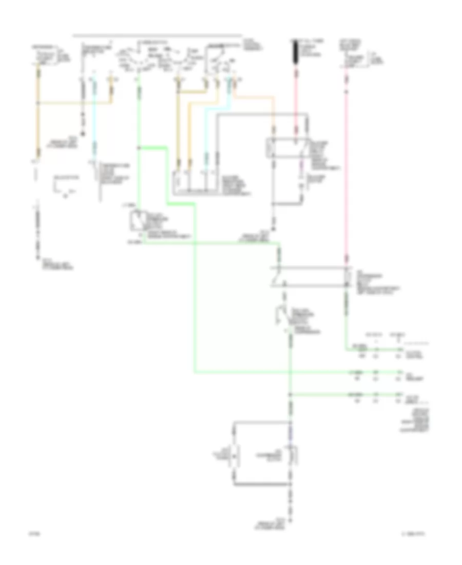
A/C Wiring Diagram, With PCM for GMC Jimmy 1995
 https://portal-diagnostov.com/license.html
Automotive Electricians Portal FZCO
Automotive Electricians Portal FZCO
https://portal-diagnostov.com/license.html
https://portal-diagnostov.com/license.html
Automotive Electricians Portal FZCO
Automotive Electricians Portal FZCO
List of elements for A/C Wiring Diagram, With PCM for GMC Jimmy 1995:
- (rear of compressor)
- (right rear of engine compartment)
- A tan
- A/c clutch diode
- A/c compressor clutch
- A/c compressor clutch relay (engine compartment, left side of cowl)
- A/c high pressure cutout switch
- A/c low pressure cutout switch
- A/c on input
- Bi-lv
- Blend
- Blower motor
- Blower motor relay (right rear of engine compartment)
- Blower resistors (right rear of engine compartment)
- Blower switch
- C 1995 vftc
- Def
- E12
- G114 (rear of left cylinder head)
- Gauges fuse 4 20a
- Hot at all times
- Hot in run
- Hot in run, bulb test or start
- Htr
- Htr a/c fuse 6 25a
- Hvac control assembly
- I/p fuse block
- Max
- Mode switch
- Nca
- Norm
- Off
- Pnk
- Powertrain control module (behind right side of i/p)
- Red
- Solid state
- Tan
- Temperature selector
- Temperature valve motor (right side of bulkhead)
- Vent
A/C Wiring Diagram, With VCM for GMC Jimmy 1995
List of elements for A/C Wiring Diagram, With VCM for GMC Jimmy 1995:
- (rear of compressor)
- (right rear of engine compartment)
- A tan
- A/c clutch diode
- A/c compressor clutch
- A/c compressor clutch relay (engine compartment, left side of cowl)
- A/c high pressure cutout switch
- A/c low pressure cutout switch
- A/c on input
- A/c request
- Bi-lv
- Blend
- Blower motor
- Blower motor relay (right rear of engine compartment)
- Blower resistors (right rear of engine compartment)
- Blower switch
- C 1995 vftc
- Clutch control
- Def
- G114 (rear of left cylinder head)
- Gauges fuse 4 20a
- Hot at all times
- Hot in run
- Hot in run, bulb test or start
- Htr
- Htr a/c fuse 6 25a
- Hvac control assembly
- I/p fuse block
- Max
- Mode switch
- Nca
- Norm
- Off
- Pnk
- Red
- Solid state
- Tan
- Temperature selector
- Temperature valve motor (right side of bulkhead)
- V6 vin w
- V6 vin z
- Vehicle control module (right side of engine compartment)
- Vent
ANTI-LOCK BRAKES
4.3L
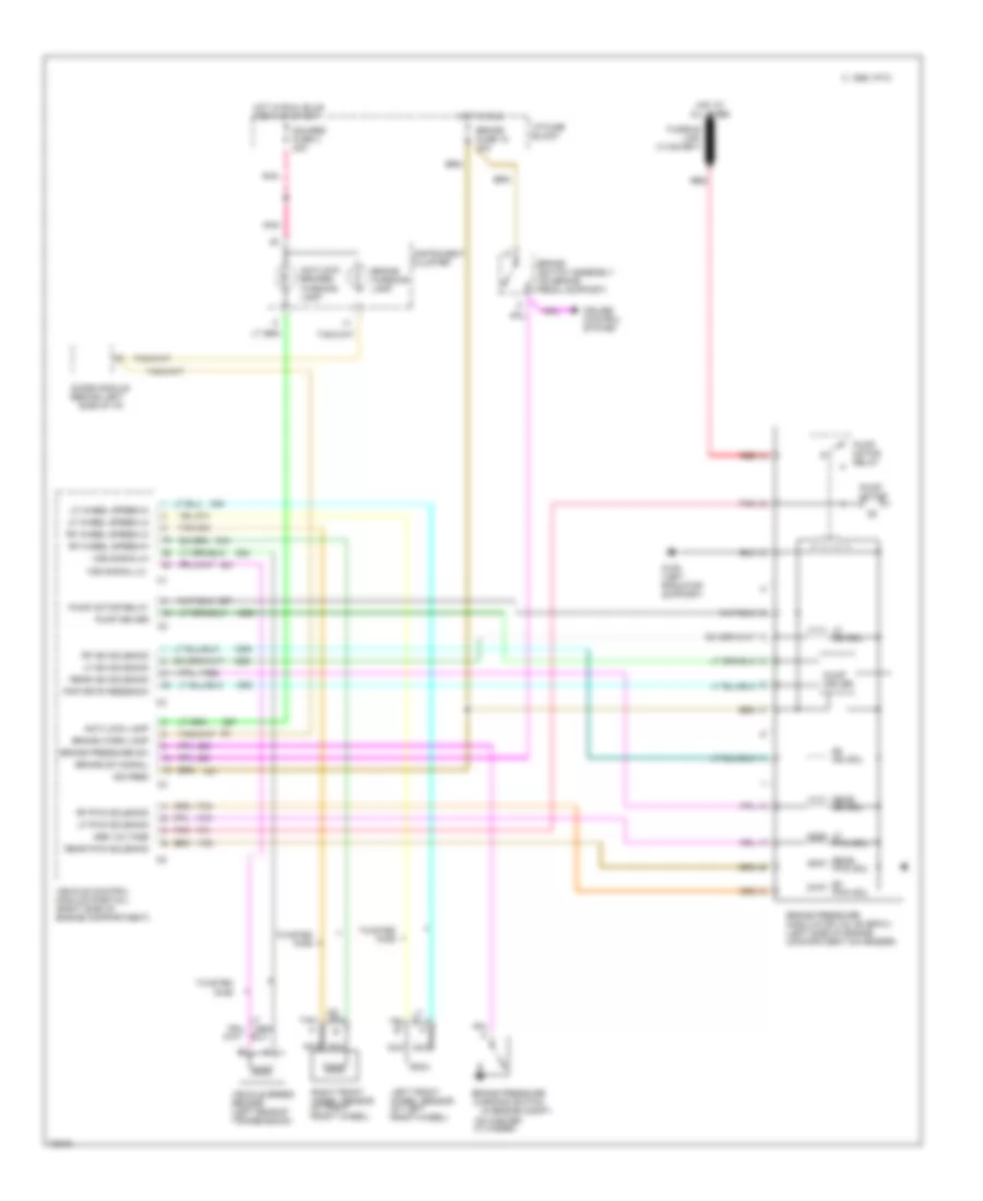
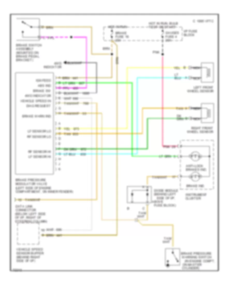
4.3L (VIN W), All-Wheel ABS Wiring Diagram, with PCM for GMC Jimmy 1995
List of elements for 4.3L (VIN W), All-Wheel ABS Wiring Diagram, with PCM for GMC Jimmy 1995:
- (behind left side of i/p,
- (in engine compt,
- 4wd indicator
- A tan
- Above
- Abs ind
- Anti-lock brakes ind.
- Brake fuse 18 20a
- Brake ind.
- Brake pressure modulator valve (left side of engine compartment, on inner fender)
- Brake pressure warning switch
- Brake sw
- Brake switch assembly (mounted on brake pedal bracket)
- Brake warn ind
- C 1995 vftc
- Cluster
- Cylinder)
- Data link connector (below left side of i/p, right of steering column)
- Diag request
- Diode module
- Fuse block)
- Gauges fuse 4 20a
- Hot in run
- Hot in run, bulb test or start
- I/p fuse block
- Ign feed
- Instrument
- Left front wheel sensor
- Lf sensor hi
- Lf sensor lo
- Nca
- On master
- Pnk
- Rf sensor hi
- Rf sensor lo
- Right front wheel sensor
- Tan
- Vehicle speed in
- Vehicle speed sensor buffer (behind right side of i/p)
4.3L (VIN W), All-Wheel ABS Wiring Diagram, with VCM for GMC Jimmy 1995
List of elements for 4.3L (VIN W), All-Wheel ABS Wiring Diagram, with VCM for GMC Jimmy 1995:
- (at left front wheel)
- (at right front wheel)
- (behind left side of i/p)
- (in engine compt,
- (on brake pedal support)
- Abs voltage
- Anti-lock lamp
- Antilock brakes warning lamp
- Brake
- Brake fuse 18 20a
- Brake pressure modulator valve (bpmv) (left side of engine compartment on fender)
- Brake pressure sw
- Brake pressure warning switch
- Brake sw signal
- Brake warn lamp
- Brake warning lamp
- C 1995 vftc
- Cruise control system
- Cylinder)
- Diode module
- G108 (left radiator support)
- Gauges fuse 4 20a
- Hot at all times
- Hot in run
- Hot in run, bulb test or start
- I/p fuse block
- Ign feed
- Instrument cluster
- Left front
- Lf iso sol
- Lf iso solenoid
- Lf pwm sol
- Lf pwm solenoid
- Lf wheel speed-hi
- Lf wheel speed-lo
- Nca
- On master
- Pmp drvr feedback
- Pnk
- Pump driver
- Pump motor
- Pump motor relay
- Rear iso sol
- Rear iso solenoid
- Rear pwm sol
- Rear pwm solenoid
- Red
- Rf iso sol
- Rf iso solenoid
- Rf pwm sol
- Rf pwm solenoid
- Rf wheel speed-hi
- Rf wheel speed-lo
- Right front
- Switch assembly
- Tan
- Twisted pair
- Vehicle control module (partial) (right side of engine compartment)
- Vehicle speed sensor (left rear of transmission)
- Vss signal-hi
- Vss signal-lo
- Wheel sensor
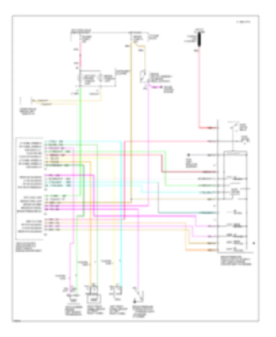
4.3L (VIN Z), All-Wheel ABS Wiring Diagram, with PCM for GMC Jimmy 1995
List of elements for 4.3L (VIN Z), All-Wheel ABS Wiring Diagram, with PCM for GMC Jimmy 1995:
- (behind left side of i/p,
- (in engine compt,
- 4wd indicator
- A tan
- Above
- Abs ind
- Anti-lock brakes ind.
- Brake fuse 18 20a
- Brake ind.
- Brake pressure modulator valve (left side of engine compartment, on inner fender)
- Brake pressure warning switch
- Brake sw
- Brake switch assembly (mounted on brake pedal bracket)
- Brake warn ind
- C 1995 vftc
- Cluster
- Cylinder)
- Data link connector (below left side of i/p, right of steering column)
- Diag request
- Diode module
- Fuse block)
- Gauges fuse 4 20a
- Hot in run
- Hot in run, bulb test or start
- I/p fuse block
- Ign feed
- Instrument
- Left front wheel sensor
- Lf sensor hi
- Lf sensor lo
- Nca
- On master
- Pnk
- Rf sensor hi
- Rf sensor lo
- Right front wheel sensor
- Tan
- Vehicle speed in
- Vehicle speed sensor buffer (behind right side of i/p)
4.3L (VIN Z), All-Wheel ABS Wiring Diagram, with VCM for GMC Jimmy 1995
List of elements for 4.3L (VIN Z), All-Wheel ABS Wiring Diagram, with VCM for GMC Jimmy 1995:
- (at left front wheel)
- (at right front wheel)
- (behind left side of i/p)
- (in engine compt,
- (on brake pedal support)
- Abs voltage
- Anti-lock lamp
- Antilock brakes warning lamp
- Brake
- Brake fuse 18 20a
- Brake ign feed
- Brake pressure modulator valve (bpmv) (left side of engine compartment on fender)
- Brake pressure sw
- Brake pressure warning switch
- Brake sw signal
- Brake warn lamp
- Brake warning lamp
- C 1995 vftc
- Cruise control system
- Cylinder)
- Diode module
- G108 (left radiator support)
- Gauges fuse 4 20a
- Hot at all times
- Hot in run
- Hot in run, bulb test or start
- I/p fuse block
- Instrument cluster
- Left front
- Lf iso sol
- Lf iso solenoid
- Lf pwm sol
- Lf pwm solenoid
- Lf wheel speed-hi
- Lf wheel speed-lo
- Nca
- On master
- Pmp drvr feedback
- Pnk
- Pump driver
- Pump motor
- Pump motor relay
- Rear iso sol
- Rear iso solenoid
- Rear pwm sol
- Rear pwm solenoid
- Red
- Rf iso sol
- Rf iso solenoid
- Rf pwm sol
- Rf pwm solenoid
- Rf wheel speed-hi
- Rf wheel speed-lo
- Right front
- Switch assembly
- Tan
- Twisted pair
- Vehicle control module (partial) (right side of engine compartment)
- Vehicle speed sensor (left rear of transmission)
- Vss signal-hi
- Vss signal-lo
- Wheel sensor
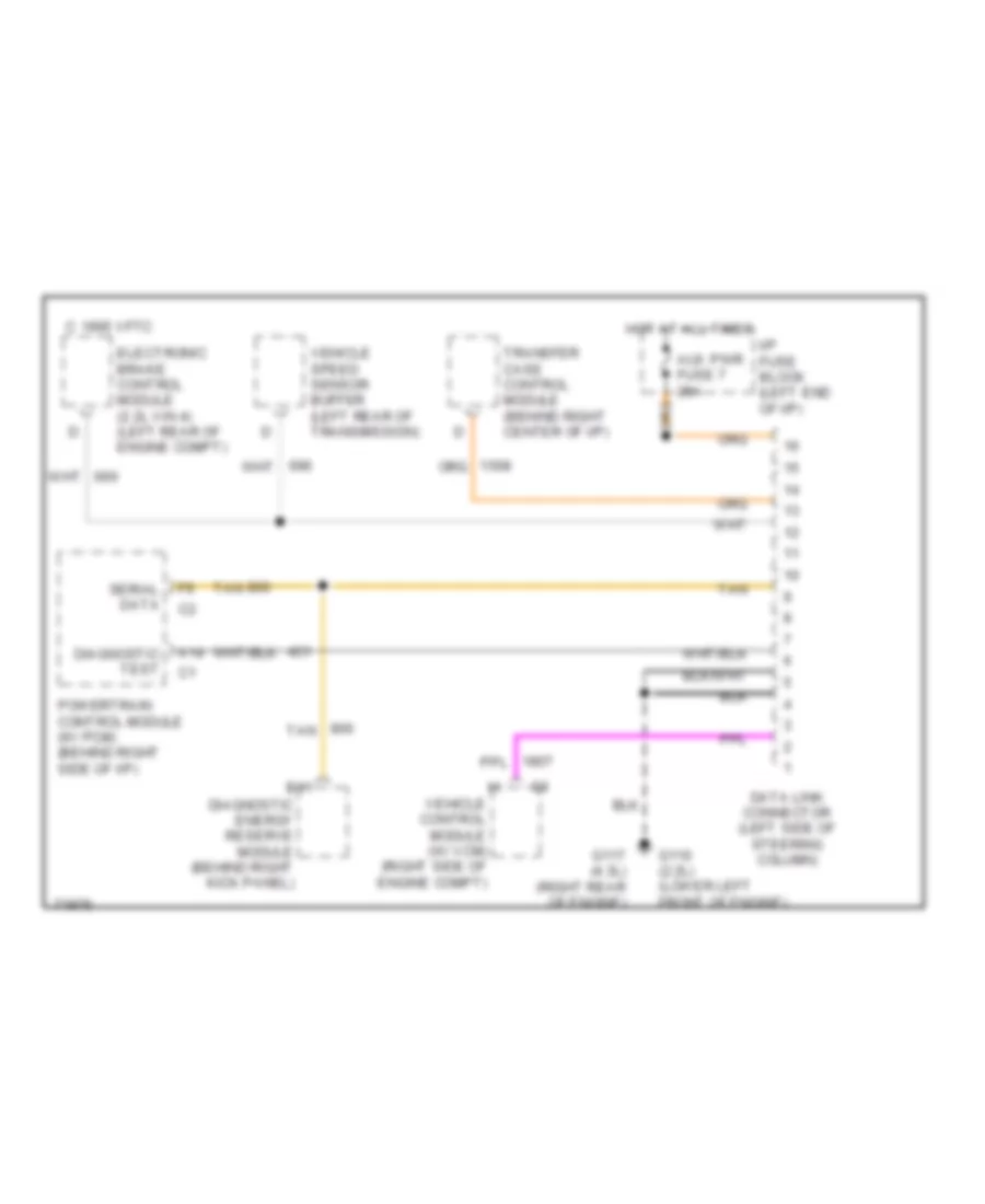
COMPUTER DATA LINES
Data Link Connector Wiring Diagram for GMC Jimmy 1995
List of elements for Data Link Connector Wiring Diagram for GMC Jimmy 1995:
- A14
- Aux pwr fuse 7 25a
- B11
- C 1995 vftc
- Data link connector (left side of steering column)
- Diagnostic energy reserve module (behind right kick panel)
- Diagnostic test
- Electronic brake control module (2.2l vin 4) (left rear of engine compt)
- G110 (2.2l) (lower left front of engine)
- G117 (4.3l) (right rear of engine)
- Hot at all times
- I/p fuse block (left end of i/p)
- Powertrain control module (w/ pcm) (behind right side of i/p)
- Serial data
- Tan
- Transfer case control module (behind right center of i/p)
- Vehicle control module (w/ vcm) (right side of engine compt)
- Vehicle speed sensor buffer (left rear of transmission)
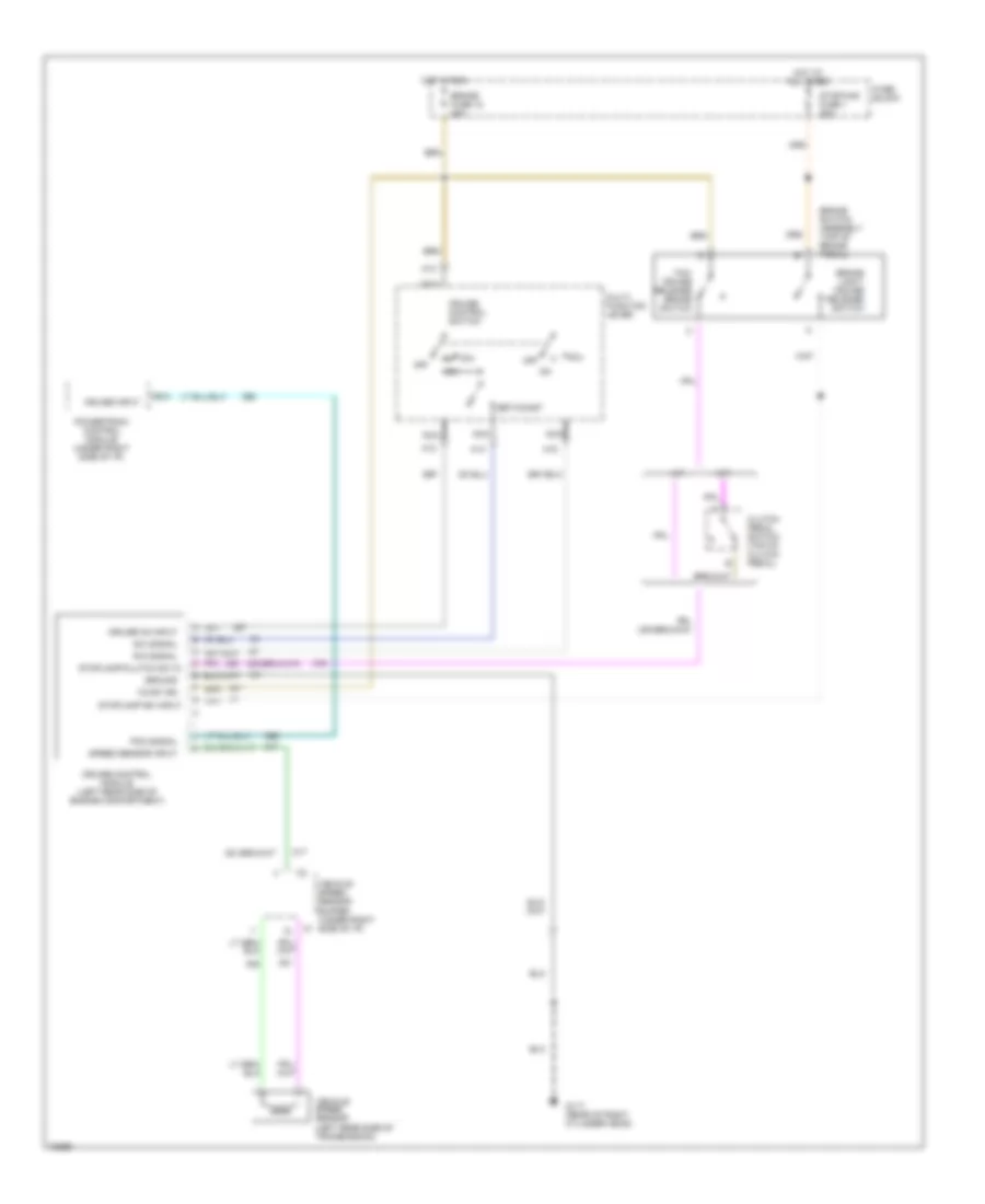
CRUISE CONTROL
4.3L
4.3L (VIN W), Cruise Control Wiring Diagram, with PCM for GMC Jimmy 1995
List of elements for 4.3L (VIN W), Cruise Control Wiring Diagram, with PCM for GMC Jimmy 1995:
- 12vdc ign
- A/t
- A12
- A13
- A14
- A15
- B10
- Brake fuse 18 20a
- Brake light/ cruise release switch
- Brake switch assembly (top of brake pedal)
- Clutch pedal switch (top of clutch pedal)
- Cruise control module (left rear side of engine compartment)
- Cruise control switch
- Cruise input
- Cruise on input
- Fuse block
- G117 (rear of right cylinder head)
- Ground
- Hot at all times
- Hot in run
- M/t
- Multi- function lever
- Nca
- Off
- Pcm signal
- Powertrain control module (under right side of i/p)
- R/a
- R/a signal
- S/c signal
- Set/coast
- Speed sensor input
- Stop/haz fuse 1 20a
- Stoplamp sw input
- Stoplamp/clutch sw in
- Tcc/ cruise release brake switch
- Vehicle speed sensor (left rear side of transmission)
- Vehicle speed sensor buffer (under right side of i/p) c1
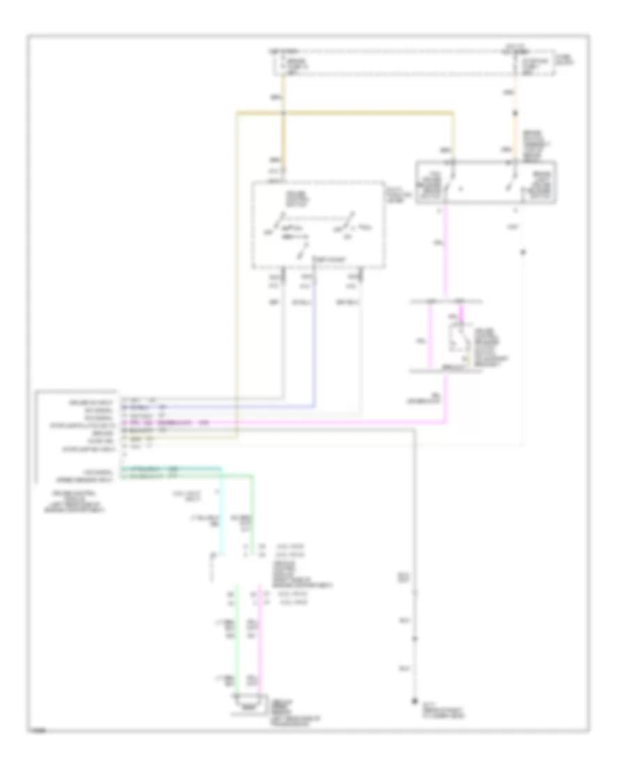
4.3L (VIN W), Cruise Control Wiring Diagram, with VCM for GMC Jimmy 1995
List of elements for 4.3L (VIN W), Cruise Control Wiring Diagram, with VCM for GMC Jimmy 1995:
- (4.3l vin w only)
- (4.3l vin w)
- (4.3l vin z)
- 12vdc ign
- A/t
- A12
- A13
- A14
- A15
- Brake fuse 18 20a
- Brake light/ cruise release switch
- Brake switch assembly (top of brake pedal)
- Cruise control module (left rear side of engine compartment)
- Cruise control release/ clutch switch (on support bracket)
- Cruise control switch
- Cruise on input
- Fuse block
- G117 (rear of right cylinder head)
- Ground
- Hot at all times
- Hot in run
- M/t
- Multi- function lever
- Nca
- Off
- R/a
- R/a signal
- S/c signal
- Set/coast
- Speed sensor input
- Stop/haz fuse 1 20a
- Stoplamp sw input
- Stoplamp/clutch sw in
- Tcc/ cruise release brake switch
- Vcm signal
- Vehicle control module (right side of engine compartment)
- Vehicle speed sensor (left rear side of transmission)
4.3L (VIN Z), Cruise Control Wiring Diagram, with PCM for GMC Jimmy 1995
List of elements for 4.3L (VIN Z), Cruise Control Wiring Diagram, with PCM for GMC Jimmy 1995:
- 12vdc ign
- A/t
- A12
- A13
- A14
- A15
- B10
- Brake fuse 18 20a
- Brake light/ cruise release switch
- Brake switch assembly (top of brake pedal)
- Clutch pedal switch (top of clutch pedal)
- Cruise control module (left rear side of engine compartment)
- Cruise control switch
- Cruise input
- Cruise on input
- Fuse block
- G117 (rear of right cylinder head)
- Ground
- Hot at all times
- Hot in run
- M/t
- Multi- function lever
- Nca
- Off
- Pcm signal
- Powertrain control module (under right side of i/p)
- R/a
- R/a signal
- S/c signal
- Set/coast
- Speed sensor input
- Stop/haz fuse 1 20a
- Stoplamp sw input
- Stoplamp/clutch sw in
- Tcc/ cruise release brake switch
- Vehicle speed sensor (left rear side of transmission)
- Vehicle speed sensor buffer (under right side of i/p) c1
4.3L (VIN Z), Cruise Control Wiring Diagram, with VCM for GMC Jimmy 1995
List of elements for 4.3L (VIN Z), Cruise Control Wiring Diagram, with VCM for GMC Jimmy 1995:
- (4.3l vin w only)
- (4.3l vin w)
- (4.3l vin z)
- 12vdc ign
- A/t
- A12
- A13
- A14
- A15
- Brake fuse 18 20a
- Brake light/ cruise release switch
- Brake switch assembly (top of brake pedal)
- Cruise control module (left rear side of engine compartment)
- Cruise control release/ clutch switch (on support bracket)
- Cruise control switch
- Cruise on input
- Fuse block
- G117 (rear of right cylinder head)
- Ground
- Hot at all times
- Hot in run
- M/t
- Multi- function lever
- Nca
- Off
- R/a
- R/a signal
- S/c signal
- Set/coast
- Speed sensor input
- Stop/haz fuse 1 20a
- Stoplamp sw input
- Stoplamp/clutch sw in
- Tcc/ cruise release brake switch
- Vcm signal
- Vehicle control module (right side of engine compartment)
- Vehicle speed sensor (left rear side of transmission)
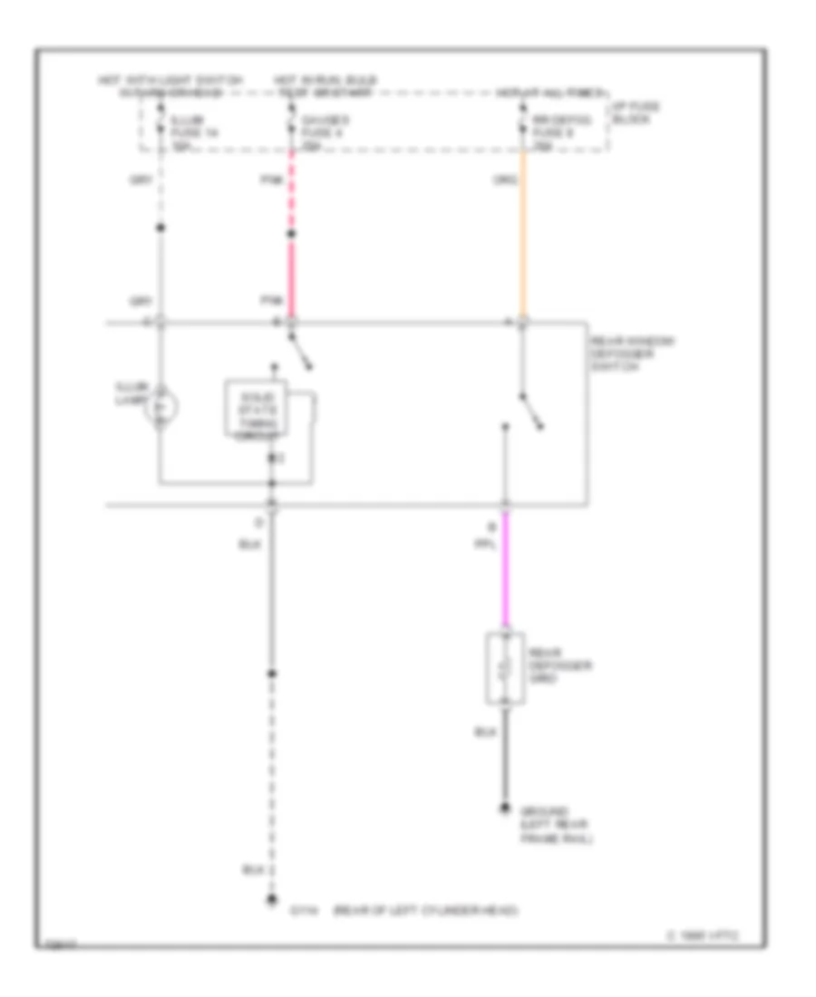
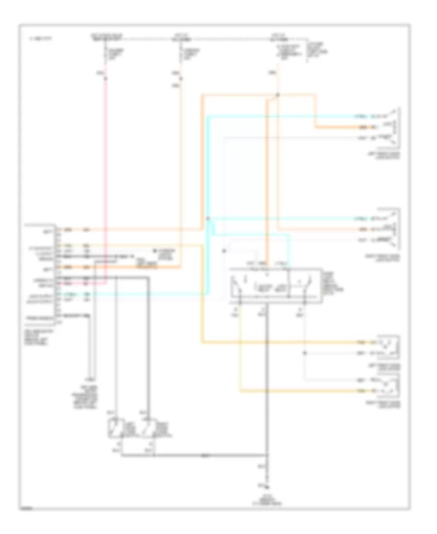
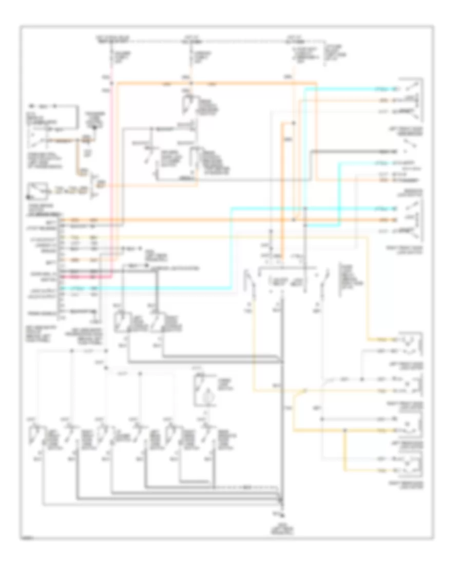
DEFOGGERS
Defogger Wiring Diagram for GMC Jimmy 1995
List of elements for Defogger Wiring Diagram for GMC Jimmy 1995:
- (left rear frame rail)
- (rear of left cylinder head)
- C 1995 vftc
- G114
- Gauges fuse 4 20a
- Ground
- Hot at all times
- Hot in run, bulb test or start
- Hot with light switch in park or head
- I/p fuse block
- Illum fuse 14 10a
- Illum. lamp
- Pnk
- Rear defogger grid
- Rear window defogger switch
- Rr defog fuse 8 30a
- Solid state timing circuit
ENGINE PERFORMANCE
4.3L
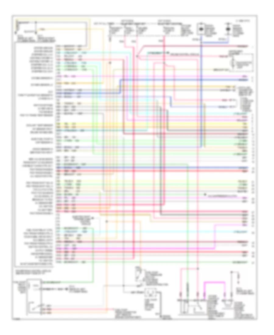
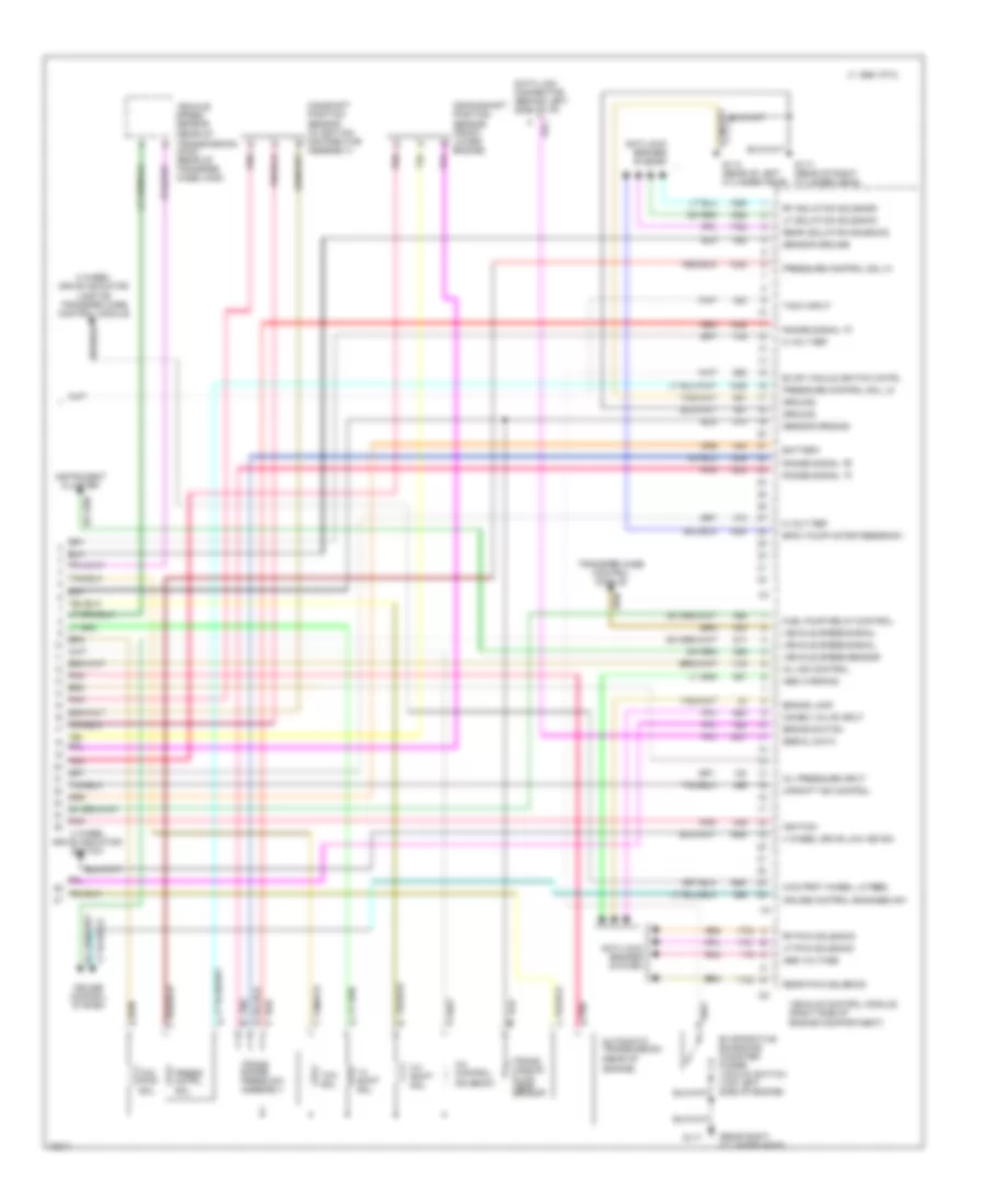
4.3L (VIN W), Engine Performance Wiring Diagrams, with PCM (1 of 2) for GMC Jimmy 1995
List of elements for 4.3L (VIN W), Engine Performance Wiring Diagrams, with PCM (1 of 2) for GMC Jimmy 1995:
- (engine compartment, right side of cowl)
- (frame ground)
- 12v battery
- 12v ignition
- 5v return b
- 5v sensor ref
- A/c compressor clutch
- A/c on signal in
- A10
- A11
- A12
- A13
- A14
- A15
- A16
- B10
- B11
- B12
- B13
- B14
- B15
- B16
- Brake sw to pcm
- Bulb test or start
- C 1995 vftc
- Coolant temp sensor
- Cruise control module
- Cruise ind reg grd
- Data link connector (behind left side of i/p)
- Distributor ref hi
- Distributor ref lo
- Dlc
- Dlc serial data
- E10
- E11
- E12
- E13
- E14
- E15
- E16
- Ecm/batt fuse 9 20a
- Ecm/ign fuse 10 20a
- Egr position input
- Egr valve solenoid
- Elec fuel pump in
- Electric shift trasfer case control module
- Eng 1 fuse 5 20a
- Evap canister purge ctrl
- F10
- F11
- F12
- F13
- F14
- F15
- F16
- Four wheel drive input
- Fuel injector (top of engine inside plenum)
- Fuel pump and sender (at fuel tank)
- Fuel pump oil pressure switch (top rear of engine, near distributor)
- Fuel pump prime connector (left rear of engine compartment)
- Fuel pump relay (inside glove box)
- Fuel pump relay ctrl
- G114 (rear of left cylinder head)
- G117 (rear of right cylinder head)
- Gauges fuse 4 20a
- Hot at all times
- Hot in run,
- I/p fuse block (behind left side of i/p)
- Iat sensor input
- Ignition bypass
- Ignition control (ic)
- Instrument cluster
- Intake manifold runner control valve (top center of intake manifold)
- Intake manifold runner control valve relay
- Knock sensor (in left cylinder head)
- Knock sensor (in right cylinder head)
- Knock sensor in
- Lo side inj a
- Malfunction indicator lamp
- Map sensor in
- Mil indicator ctrl
- Output speed
- Oxygen sensor hi
- Oxygen sensor lo
- Pcm to trans temp sensor
- Pcm trans force mtr hi
- Pcm trans force mtr lo
- Pcm trans range a
- Pcm trans range b
- Pcm trans range c
- Pcm trans shift sol a
- Pcm trans shift sol b
- Pnk
- Powertrain control module (behind right side of i/p)
- Pwm tcc solenoid
- Red
- Stepper coil a hi
- Stepper coil a lo
- Stepper coil b hi
- Stepper coil b lo
- System ground
- Tan
- Tcc clutch ctrl
- Tcc enable
- Throttle position sensor in
- Trans shift 2/3 solenoid
- Variable tuning ctrl rly
- Vss buffer signal
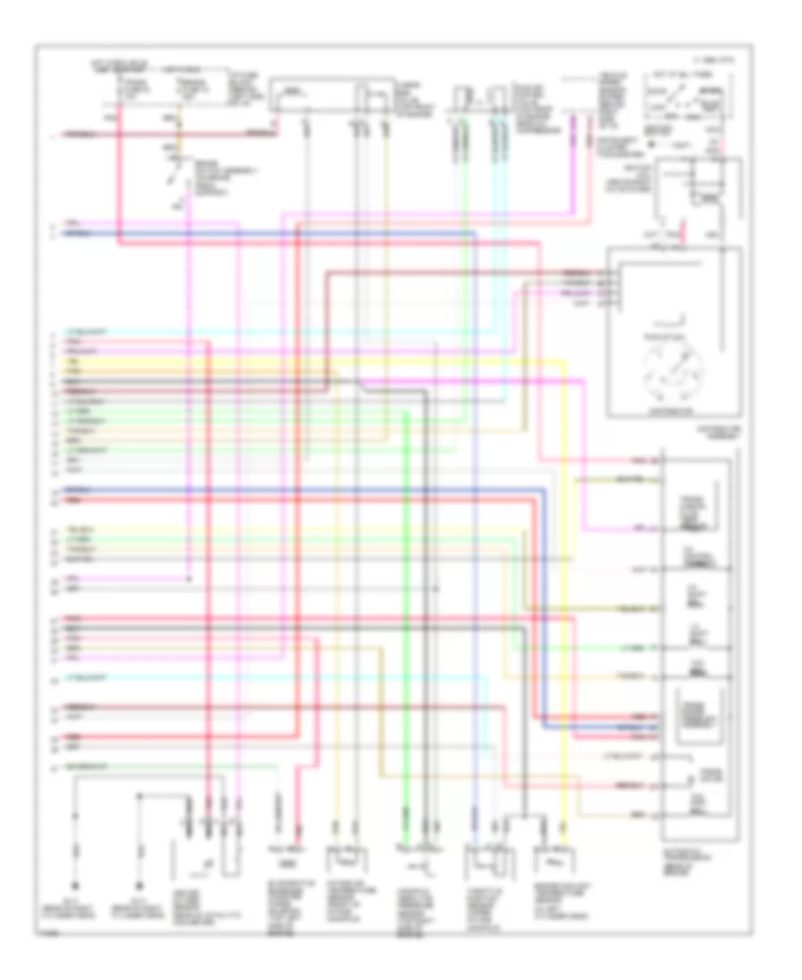
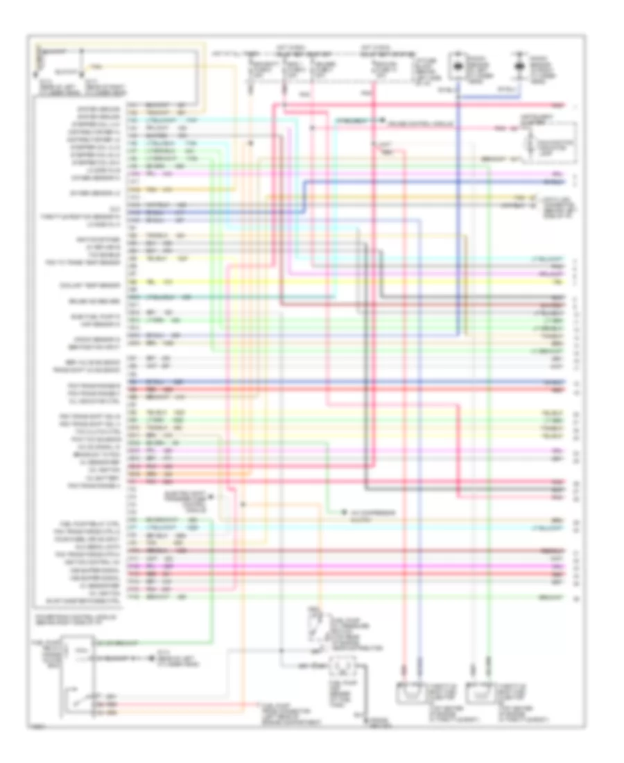
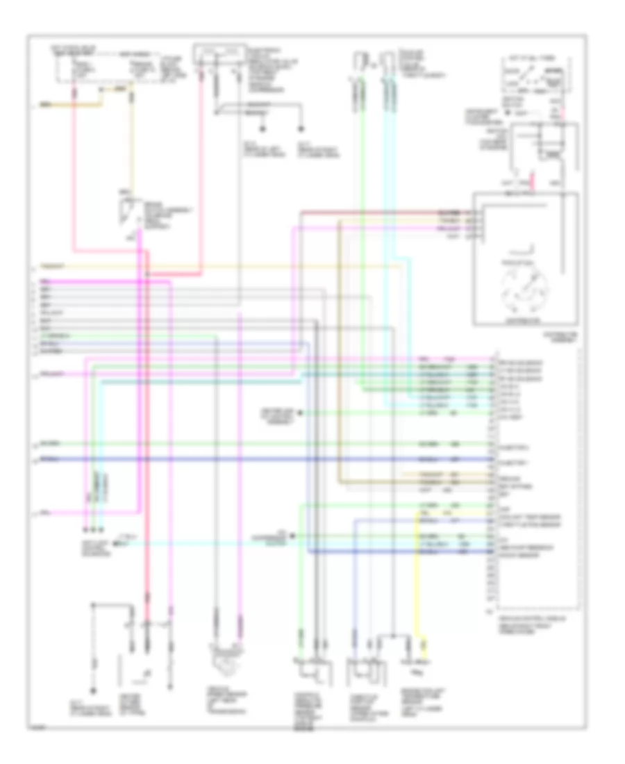
4.3L (VIN W), Engine Performance Wiring Diagrams, with PCM (2 of 2) for GMC Jimmy 1995
List of elements for 4.3L (VIN W), Engine Performance Wiring Diagrams, with PCM (2 of 2) for GMC Jimmy 1995:
- (in left cylinder head)
- (rear of engine)
- (rear of right cylinder head)
- 1-2 shift sol
- 2-3 shift sol
- 3-2 control solenoid
- Accy
- Automatic transmission
- B nca
- Brake fuse 18 20a
- Brake switch assembly (on brake pedal support)
- Bulb test
- C 1995 vftc
- C nca
- C11 red
- D nca
- Distributor
- Distributor assembly
- Engine coolant temperature sensor
- Evaporative emissions canister purge solenoid (top left side of engine)
- Force motor
- G117
- Heated oxygen sensor (rear of catalytic converter)
- Hot at all times
- Hot in run
- Hot in run, bulb test or start
- I/p fuse block (behind left side of i/p)
- Idle air control valve (top front of engine near a/c compressor)
- Ignition coil (above right valve cover)
- Ignition switch
- Instrument cluster (tachometer)
- Intake air temperature sensor (front of intake manifold)
- Linear egr valve (top front of engine)
- Lock
- Manifold absolute pressure sensor (top right side of engine)
- Nca
- Off
- Pick-up coil
- Pnk
- Red
- Run
- Start
- Tan
- Tcc pwm sol
- Tcc sol
- Throttle position sensor (upper intake manifold)
- Trans range press sw assembly
- Trans fuse 23 10a
- Trans- mission fluid temp sensor
- Vehicle speed sensor buffer (behind right side of i/p)
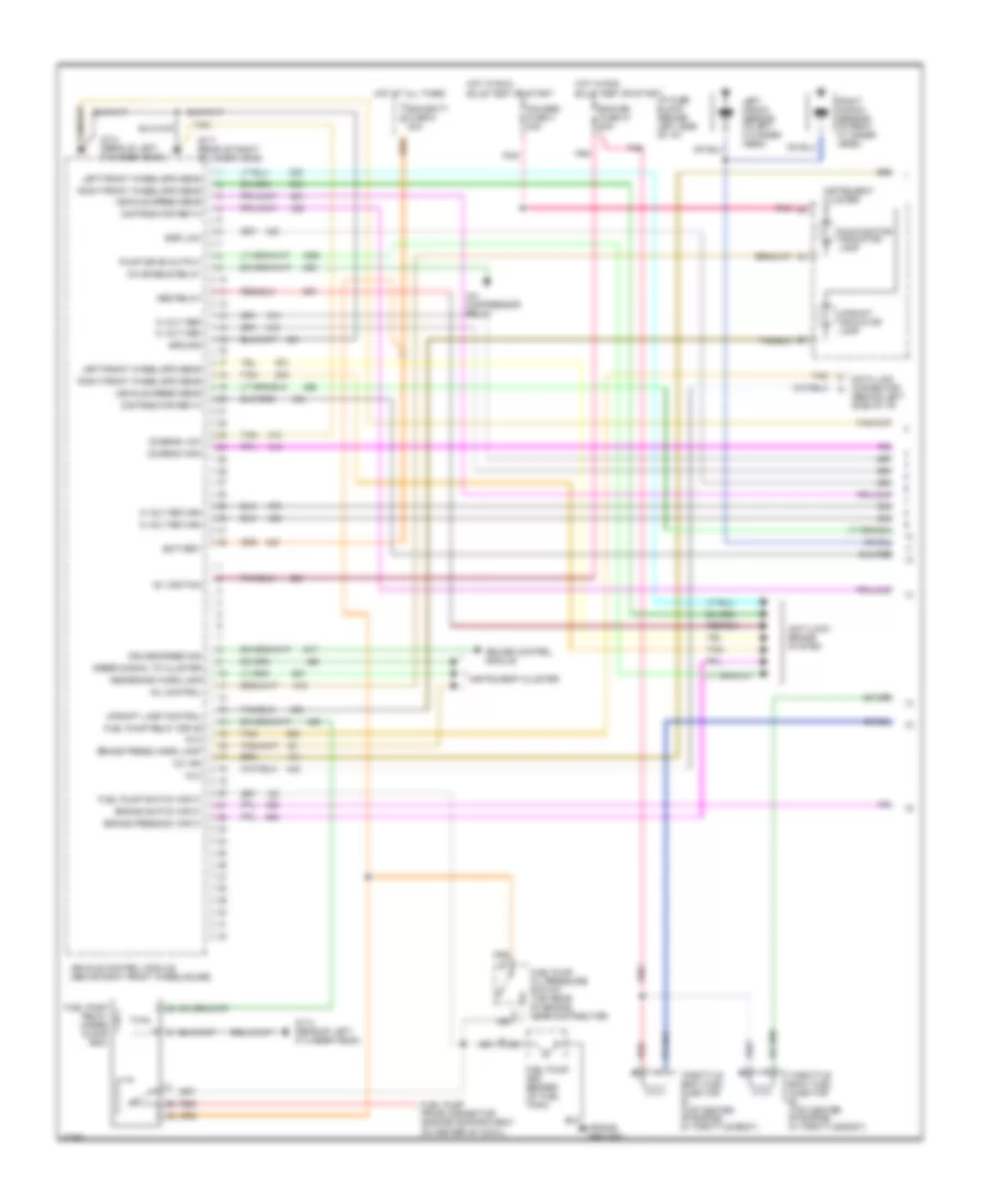
4.3L (VIN W), Engine Performance Wiring Diagrams, with VCM (1 of 3) for GMC Jimmy 1995
List of elements for 4.3L (VIN W), Engine Performance Wiring Diagrams, with VCM (1 of 3) for GMC Jimmy 1995:
- (engine compartment, right side of cowl)
- (frame ground)
- 1-2 shift sol control
- 2-3 shift sol control
- 3-2 control sol control
- Abs enable
- Abs pump motor
- Anti-lock brakes system
- Bulb test or start
- C 1995 vftc
- Camshaft pos sens ret
- Camshaft pos sens sig
- Catalyst 02 sensor hi
- Catalyst 02 sensor lo
- Crankshaft pos sens ret
- Crankshaft pos sens sig
- Ecm/batt fuse 9 20a
- Ecm/ign fuse 10 20a
- Egr ground
- Egr position input
- Eng 1 fuse 5 20a
- Etc sensor input
- Evap valve control
- Exhaust 02 sensor hi
- Exhaust 02 sensor lo
- Fr wheel speed lo
- Fuel injector (top of engine inside plenum)
- Fuel injector control
- Fuel pump and sender (at fuel tank)
- Fuel pump oil pressure switch (top rear of engine, near distributor)
- Fuel pump prime connector (left rear of engine compartment)
- Fuel pump relay (inside glove box)
- G114 (rear of left cylinder head)
- Gauges fuse 4 20a
- Hot at all times
- Hot in run,
- I/p fuse block (behind left side of i/p)
- Idle air valve control
- Idle air valve control bat
- Ignition
- Instrument cluster
- Intake air temp sens signal
- Intake manifold runner control valve (top center of intake manifold)
- Intake manifold runner control valve relay
- Knock sensor signal
- Left knock sensor (in left cylinder head)
- Lf wheel speed hi
- Lf wheel speed lo
- M/t only
- Malfunction indicator lamp
- Map sensor input
- Pnk
- Red
- Rf wheel speed hi
- Right knock sensor (in right cylinder head)
- Tan
- Tcc on/off sol control
- Tcc pwm sol control
- Tft signal
- Tp sensor input
- Upshift indicator lamp
- Variable tuning relay cntrl
- Vehicle control module (right side of engine compartment)
- Vss hi
- Vss lo
4.3L (VIN W), Engine Performance Wiring Diagrams, with VCM (2 of 3) for GMC Jimmy 1995
List of elements for 4.3L (VIN W), Engine Performance Wiring Diagrams, with VCM (2 of 3) for GMC Jimmy 1995:
- (above right valve cover)
- (in left cylinder head)
- (on brake pedal support)
- (rear of left cylinder head)
- (rear of right cylinder head)
- Acc
- B nca
- Brake fuse 18 20a
- Brake switch assembly
- Bulb test
- C 1995 vftc
- C nca
- D nca
- Distributor
- Engine coolant temperature sensor
- Evaporative emissions canister purge solenoid valve (top left side of engine)
- G114
- G117
- Ground
- Heated oxygen sensor (h02s) 1 (front of catalytic converter)
- Heated oxygen sensor (ho2s) 2 (rear of catalytic converter)
- Hot at all times
- Hot in run
- Hot in run, bulb test or start
- I/p fuse block (behind left side of i/p)
- Idle air control valve (top front of engine near a/c compressor)
- Ignition
- Ignition coil (above right valve cover)
- Ignition coil driver module
- Ignition switch
- Ignition timing
- Instrument cluster (tachometer)
- Intake air temperature sensor (front of intake manifold)
- Linear exhaust gas recirculation (egr) valve (top front of engine)
- Lock
- Manifold absolute pressure sensor (top of engine)
- Nca
- Off
- Pnk
- Pnk pnk d
- Run
- Start
- Tach signal
- Tan
- Throttle position sensor (upper intake manifold)
- Trans fuse 23 10a
4.3L (VIN W), Engine Performance Wiring Diagrams, with VCM (3 of 3) for GMC Jimmy 1995
List of elements for 4.3L (VIN W), Engine Performance Wiring Diagrams, with VCM (3 of 3) for GMC Jimmy 1995:
- (4wd)
- (rear of engine)
- (rear of transmission) (2wd) (rear of transfer case)
- (rear right cylinder head)
- 1-2 shift sol
- 2-3 shift sol
- 3-2 control solenoid
- 4 wheel drive indicator lamp or transfer case control module
- 4 wheel drive indicator switch
- 4 wheel drive low ind sig
- 4wd frnt wheel lk feed
- 5 volt ref
- Abs voltage
- Abs warning
- Anti-lock brakes system
- Automatic transmission
- Battery
- Bpmv pump motor feedback
- Brake lamp
- Brake switch
- C 1995 vftc
- C pnk
- Camshaft position sensor (in ignition distributor assembly)
- Combo valve input
- Crankshaft position sensor (front lower engine)
- Cruise control engaged sw
- Cruise control system
- Data link connector (behind left side of i/p)
- Evap vacuum switch cntrl
- Evaporative emissions canister purge vacuum switch (top left side of engine)
- Fuel pump relay control
- G114 (rear of left cylinder head)
- G117
- G117 (rear of right cylinder head)
- Ground
- Ignition
- Instrument cluster
- Lf isolation solenoid
- Lf pwm solenoid
- Mil ind control
- Oil pressure input
- Pnk
- Pnk e
- Press cntrl sol
- Pressure control sol hi
- Pressure control sol lo
- Range signal "a"
- Range signal "b"
- Range signal "c"
- Rear isolation solenoid
- Rear pwm solenoid
- Red
- Red p
- Rf isolation solenoid
- Rf pwm solenoid
- Sensor ground
- Serial data
- Tach input
- Tcc pwm sol
- Tcc sol
- Trans range press sw assembly
- Trans- mission fluid temp sensor
- Transfer case control module
- Upshift ind control
- Vehicle control module (right side of engine compartment)
- Vehicle speed sensor
- Vehicle speed signal
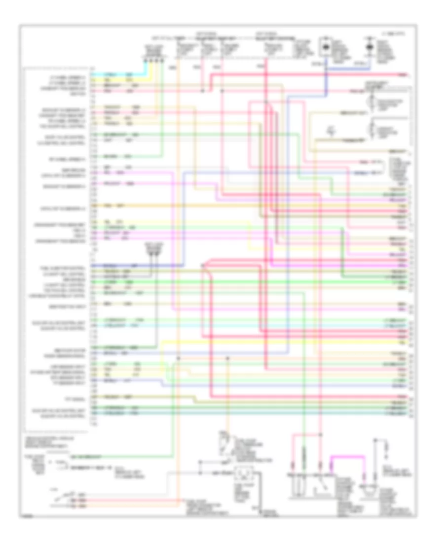
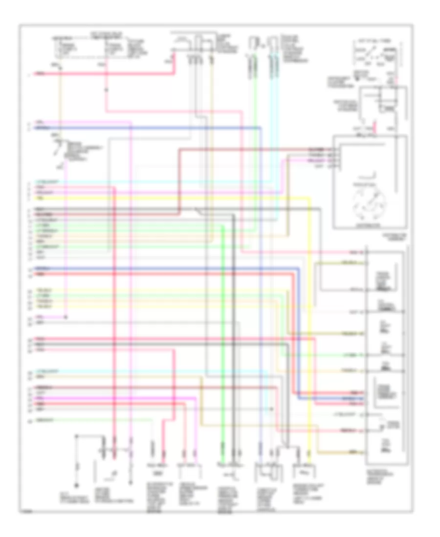
4.3L (VIN Z), Engine Performance Wiring Diagrams, with PCM (1 of 2) for GMC Jimmy 1995
List of elements for 4.3L (VIN Z), Engine Performance Wiring Diagrams, with PCM (1 of 2) for GMC Jimmy 1995:
- (frame ground)
- 12v battery
- 12v ignition
- 5v return b
- 5v sensor ref
- A/c compressor
- A/c on signal in
- A10
- A11
- A12
- A13
- A14
- A15
- A16
- B10
- B11
- B12
- B13
- B14
- B15
- B16
- Brake sw to pcm
- Bulb test or start
- Clutch
- Coolant temp sensor
- Cruise control module
- Cruise ind reg grd
- Data link connector (behind left side of i/p)
- Distributor ref hi
- Distributor ref lo
- Dlc
- Dlc serial data
- E10
- E11
- E12
- E13
- E14
- E15
- E16
- Ecm/batt fuse 9 20a
- Ecm/ign fuse 10 20a
- Egr position input
- Egr valve solenoid
- Elec fuel pump in
- Electric shift transfer case control module
- Eng 1 fuse 5 20a
- Evap canister purge ctrl
- F10
- F11
- F12
- F13
- F14
- F15
- F16
- Four wheel drive input
- Fuel pump and sender (at fuel tank)
- Fuel pump oil pressure switch (top rear of engine, near distributor)
- Fuel pump prime connector (left rear of engine compartment)
- Fuel pump relay (inside glove box)
- Fuel pump relay ctrl
- G114 (rear of left cylinder head)
- G117 (rear of right cylinder head)
- Gauges fuse 4 20a
- Hot at all times
- Hot in run,
- I/p fuse block (behind left side of i/p)
- Ignition bypass
- Ignition control (ic)
- Instrument cluster
- Knock sensor (in left cylinder head)
- Knock sensor (in right cylinder head)
- Knock sensor in
- Lo side inj a
- Lo side inj b
- Malfunction indicator lamp
- Map sensor in
- Mil indicator ctrl
- Oxygen sensor hi
- Oxygen sensor lo
- Pcm to trans temp sensor
- Pcm trans force mtr hi
- Pcm trans force mtr lo
- Pcm trans range a
- Pcm trans range b
- Pcm trans range c
- Pcm trans shift sol a
- Pcm trans shift sol b
- Pnk
- Powertrain control module (behind right side of i/p)
- Pwm tcc solenoid
- Red
- Stepper coil a hi
- Stepper coil a lo
- Stepper coil b hi
- Stepper coil b lo
- System ground
- Tan
- Tcc clutch ctrl
- Tcc enable
- Throttle body fuel injector #1 (top center of engine in throttle body)
- Throttle body fuel injector #2 (top center of engine in throttle body)
- Throttle position sensor in
- Trans shift 2/3 solenoid
- Vss buffer signal
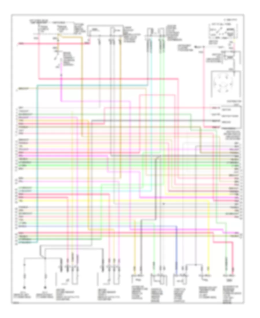
4.3L (VIN Z), Engine Performance Wiring Diagrams, with PCM (2 of 2) for GMC Jimmy 1995
List of elements for 4.3L (VIN Z), Engine Performance Wiring Diagrams, with PCM (2 of 2) for GMC Jimmy 1995:
- (left cylinder head)
- (rear of engine)
- 1-2 shift sol
- 2-3 shift sol
- 3-2 control solenoid
- A pnk
- Accy
- Automatic transmission
- Brake fuse 18 20a
- Brake switch assembly (on brake pedal support)
- Bulb test
- C11
- C13
- Distributor
- Distributor assembly
- Engine coolant tmperature sensor
- Evaporative emissions canister purge solenoid (top left side of engine)
- Force motor
- G117 (rear of right cylinder head)
- Heated oxygen sensor (in cross over pipe)
- Hot at all times
- Hot in run
- Hot in run, bulb test or start
- I/p fuse block (behind left side of i/p)
- Idle air control valve (top front of engine near a/c compressor)
- Ignition coil (top rear of engine)
- Ignition switch
- Instrument cluster (tachometer)
- Linear egr valve (top front of engine)
- Lock
- Manifold absolute pressure sensor (top right side of engine)
- Nca
- Off
- Pick-up coil
- Pnk
- Red
- Run
- Start
- Tcc pwm sol
- Tcc sol
- Throttle position sensor (upper intake manifold)
- Trans range press sw assembly
- Trans fuse 23 10a
- Trans- mission fluid temp sensor
- Vehicle speed sensor buffer (behind right side of i/p)
4.3L (VIN Z), Engine Performance Wiring Diagrams, with VCM (1 of 2) for GMC Jimmy 1995
List of elements for 4.3L (VIN Z), Engine Performance Wiring Diagrams, with VCM (1 of 2) for GMC Jimmy 1995:
- (frame ground)
- 12v ign
- 12v ignition
- 5 volt ref
- 5 volt return
- A/c compressor relay
- A/c enable relay
- Abs brake warn lamp
- Abs relay
- Anti-lock brake system
- Battery
- Brake press sw input
- Brake press warn lamp
- Brake switch input
- Bulb test or start
- Cruise control module
- Cruise speed sig
- Data link connector (behind left side of i/p)
- Distributor ref hi
- Dlc
- Ecm/batt fuse 9 20a
- Ecm/ign fuse 10 20a
- Egr low
- Fuel pump and sender (at fuel tank)
- Fuel pump oil pressure switch (top rear of engine, near distributor)
- Fuel pump prime connector (engine compartment on center of cowl)
- Fuel pump relay (inside glove box)
- Fuel pump relay drive
- Fuel pump switch input
- G114 (rear of left cylinder head)
- G117 (rear of right cylinder head)
- Gauges fuse 4 20a
- Ground
- Hot at all times
- Hot in run,
- I/p fuse block (behind left side of i/p)
- Instrument cluster
- Left front wheel spd sens
- Left knock sensor (in left cylinder head)
- Malfunction indicator lamp
- Mil control
- O2 sens high
- O2 sens low
- Pnk
- Pump drive output
- Red
- Right front wheel spd sens
- Right knock sensor (in right cylinder head)
- Speed signal to cluster
- Tan
- Throttle body fuel injector #1 (top center of engine in throttle body)
- Throttle body fuel injector #2 (top center of engine in throttle body)
- Upshift indicator lamp
- Upshift lamp control
- Vehicle control module (above right front wheelhouse)
- Vehicle speed sens
4.3L (VIN Z), Engine Performance Wiring Diagrams, with VCM (2 of 2) for GMC Jimmy 1995
List of elements for 4.3L (VIN Z), Engine Performance Wiring Diagrams, with VCM (2 of 2) for GMC Jimmy 1995:
- (above right front wheelhouse)
- (left cylinder head)
- A pnk
- A/c
- A/c assy
- A/c compressor clutch
- Abs pump feedback
- Accy
- Anti-lock control solenoids
- Brake fuse 18 20a
- Brake switch assembly (on brake pedal support)
- Bulb test
- Coolant temp sensor
- Distributor
- Distributor assembly
- Electronic vacuum regulator valve solenoid (evrv) (top front of engine near a/c compressor)
- Eng 1 fuse 5 20a
- Engine coolant temperature sensor
- Est
- Est bypass
- G114 (rear of left cylinder head)
- G117 (rear of right cylinder head)
- Ground
- Heated oxygen sensor (in y-pipe)
- Heater and a/c control assembly
- Hot at all times
- Hot in run
- Hot in run, bulb test or start
- I/p fuse block (behind left side of i/p)
- Iac a hi
- Iac a lo
- Iac b hi
- Iac b lo
- Idle air control valve (rear of throttle body)
- Ignition coil (top rear of engine)
- Ignition switch
- Injector 1
- Injector 2
- Instrument cluster (tachometer)
- Knock sensor
- Lf iso solenoid
- Lock
- Manifold absolute pressure sensor (top right side of engine)
- Map
- Nca
- Off
- Pick-up coil
- Pnk
- Rf iso solenoid
- Rr iso solenoid
- Run
- Start
- Throttle pos sensor
- Throttle position sensor (upper intake manifold)
- Vehicle control module
- Vehicle speed sensor (left rear of transmission)
EXTERIOR LIGHTS
Exterior Light Wiring Diagram for GMC Jimmy 1995
List of elements for Exterior Light Wiring Diagram for GMC Jimmy 1995:
- (left radiator support)
- (on brake pedal support bracket)
- (rear of right cyl. head)
- (right radiator support)
- A/t
- Auxiliary lead (taped near junction block)
- Backup light switch (top left side of trans- mission)
- Center high mounted stop lamp
- Convenience center (behind center of i/p)
- Cruise control system
- G108
- G109
- G117
- G404 (left rear frame rail)
- Hazard
- Hazard flasher
- Head
- Headlight switch
- Hot at all times
- Hot in run, bulb test or start
- I/p fuse block (left side of i/p)
- In-line fuse 30a
- Instrument cluster
- Interior lights system
- Junction block (left rear engine compt)
- Left backup light
- Left front marker light
- Left front park/ turn light
- Left tail/ stop/ turn lights
- Left turn & hazard
- Left turn ind.
- License light
- M/t
- Nca
- Normal
- Off
- Park
- Park/ neutral position switch (left side of trans- mission)
- Pnk
- Red
- Right backup light
- Right front marker light
- Right front park/ turn light
- Right tail/ stop/ turn lights
- Right turn & hazard
- Right turn ind.
- Stop -hz fuse 1 15a
- Stop lamp switch
- T/l ctsy fuse 3 20a
- To trailer wiring, or connected to trailer wire plug
- Turn b/u fuse 16 15a
- Turn flasher
- Turn- hazard switch
- W/optional trailer tow package
- Wire leads are spliced
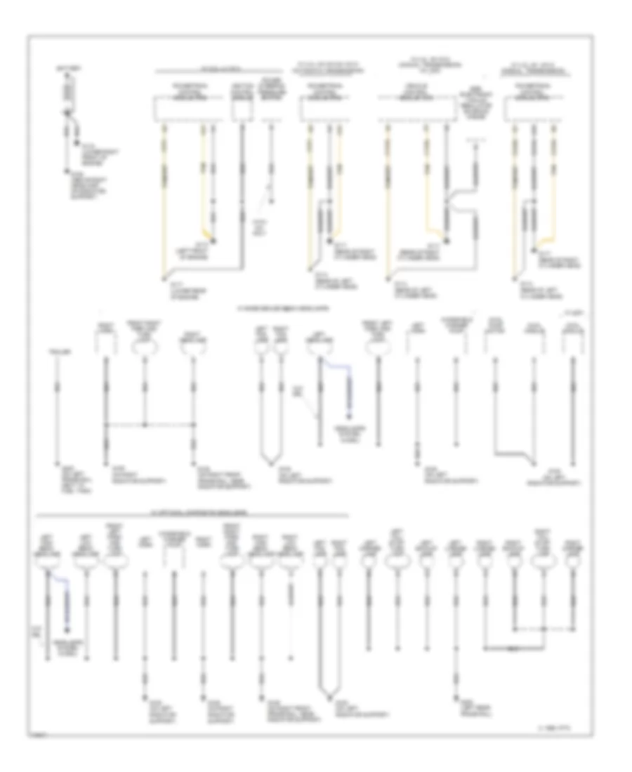
GROUND DISTRIBUTION
Ground Distribution Wiring Diagram (1 of 2) for GMC Jimmy 1995
List of elements for Ground Distribution Wiring Diagram (1 of 2) for GMC Jimmy 1995:
- (lower rear of engine)
- (on right radiator support)
- 4wal module
- 4wal pump motor
- A12
- Battery
- C 1995 vftc
- C111a
- C112a
- C211
- C211a
- C213a
- Egr electronic vacuum regulator solenoid valve
- Front left park and turn lamp
- Front right park and turn lamp
- G108 (on left radiator support)
- G109
- G109 (above right headlamp, on radiator support)
- G109 (on right front frame rail, near radiator support)
- G109 (on right radiator support)
- G110 (left front of engine)
- G114 (rear of left cylinder head)
- G117
- G117 (rear of right cylinder head)
- G119 (lower right front of engine)
- G402 (left rear frame rail)
- G402 (on left frame rail, next to fuel tank)
- Headlamps system (w/drl)
- Ignition control module
- Left backup lamp
- Left fog lamp
- Left headlamp
- Left high beam headlamp
- Left horn
- Left license lamp
- Left low beam headlamp
- Left marker lamp
- Left tail/ stop- turn lamp
- Power steering pressure switch
- Powertrain control module (pcm)
- Right backup lamp
- Right fog lamp
- Right headlamp
- Right high beam headlamp
- Right horn
- Right license lamp
- Right low beam headlamp
- Right marker lamp
- Right tail/ stop- turn lamp
- Tan
- Trailer
- Vehicle control module (vcm)
- W/ 2.2l l4 vin 4
- W/ 4.3l v6 vin w (manual transmission)
- W/ 4.3l v6 vin z & vin w (automatic transmission)
- W/ 4.3l v6 vin z (manual transmission) (w/ vcm)
- W/ base sealed beam headlamps
- W/ optional composite headlamps
- W/ vcm
- W/o drl
- Windshield washer pump
- With a/c only
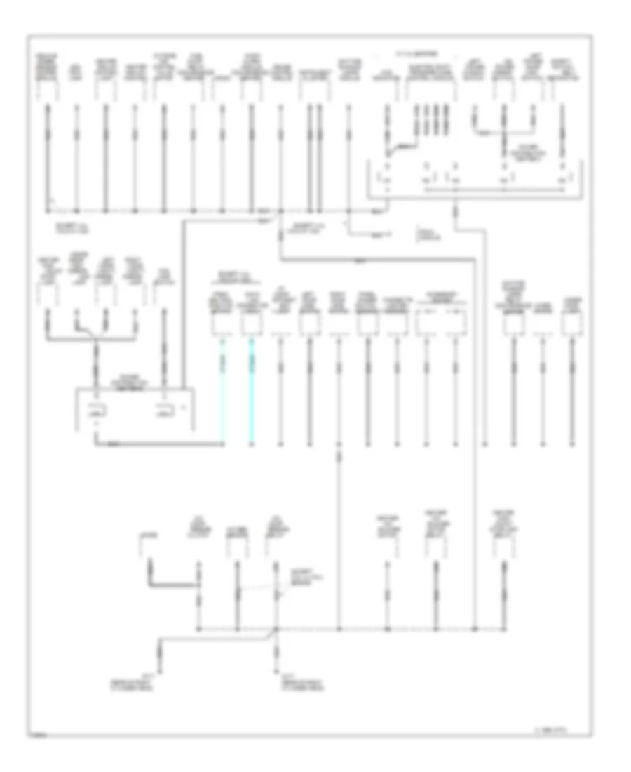
Ground Distribution Wiring Diagram (2 of 2) for GMC Jimmy 1995
List of elements for Ground Distribution Wiring Diagram (2 of 2) for GMC Jimmy 1995:
- (rear of right cylinder head)
- 4wd indicator
- A/c comp- ressor
- Accessory socket
- Ash tray lamp
- Assembly
- Audio alarm module convenience center
- Belt
- Box
- C 1995 vftc
- C10
- C231 a
- C235 c
- C503
- C85
- C86
- Center high
- Center high mount stoplamp relay
- Cigarette lighter assembly
- Clutch
- Connector (dlc)
- Cruise control module
- D10
- D12
- D13
- Data
- Daytime running lamps module
- Daytime running lamps relay convenience center
- Diode
- Electric shift transfer case control module
- Except 2.2l l4 vin 4 engine
- Except 4.3l
- Except 4.3l vin z w/ vcm
- Fog lamp switch
- Fuel
- G117
- Heater and a/c control lamp
- Heater and a/c control
- Heater- a/c blower
- I/p comp- artment
- Inside
- Instrument cluster
- Lamp
- Left
- Left power
- Left door jamb
- Left power door lock switch
- Link
- Map
- Mirror lamp
- Mirror switch
- Motor
- Motor relay
- Mount
- Nca
- O/s
- Outside air control valve motor
- Oxygen sensor
- Panel dimmer switch
- Park/ neutral position switch
- Power
- Power distribution center a
- Power distribution center b
- Pump relay convenience center
- Radio
- Rear view mirror
- Relay
- Retractor
- Right door jamb
- Right visor vanity
- Rwal module
- Safety switch
- Stop- lamp
- Switch
- Under- hood lamp
- Vehicle speed sensor buffer module
- Vin z w/ vcm
- Visor vanity
- W/ 4.3l engines
- Window switch
- Wiper motor
HEADLIGHTS
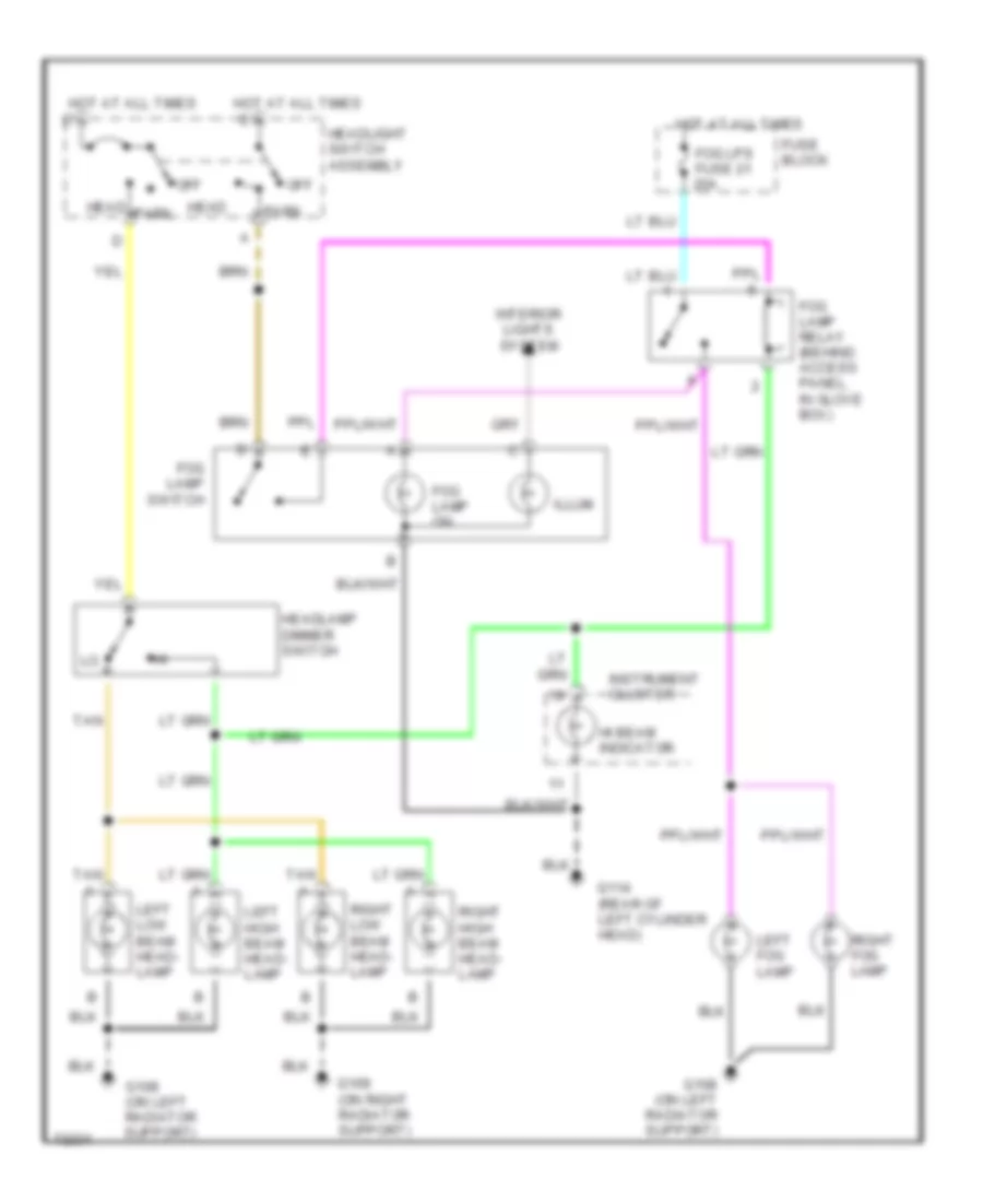
Fog Lamp Wiring Diagram, Composite without DRL for GMC Jimmy 1995
List of elements for Fog Lamp Wiring Diagram, Composite without DRL for GMC Jimmy 1995:
- Fog lamp on
- Fog lamp relay (behind access panel, in glove box)
- Fog lamp switch
- Fog lps fuse 21 20a
- Fuse block
- G108 (on left radiator support)
- G109 (on right radiator support)
- G114 (rear of left cylinder head)
- Head
- Headlamp dimmer switch
- Headlight switch assembly
- Hi beam indicator
- Hot at all times
- Illum
- Instrument cluster
- Interior lights system
- Left fog lamp
- Left high beam head- lamp
- Left low beam head- lamp
- Off
- Park
- Right fog lamp
- Right high beam head- lamp
- Right low beam head- lamp
- Tan
Fog Lamps Wiring Diagram, Sealed Beam without DRL for GMC Jimmy 1995
List of elements for Fog Lamps Wiring Diagram, Sealed Beam without DRL for GMC Jimmy 1995:
- Fog lamp on
- Fog lamp relay (behind access panel, in glove box)
- Fog lamp switch
- Fog lps fuse 21 20a
- Fuse block
- G108 (on left radiator support)
- G109 (on right radiator support)
- G114 (rear of left cylinder head)
- Head
- Headlamp dimmer switch
- Headlight switch assembly
- Hi beam indicator
- Hot at all times
- Illum
- Instrument cluster
- Interior lights system
- Left fog lamp
- Left headlamp assembly
- Off
- Park
- Right fog lamp
- Right headlamp assembly
- Tan
- Tan c
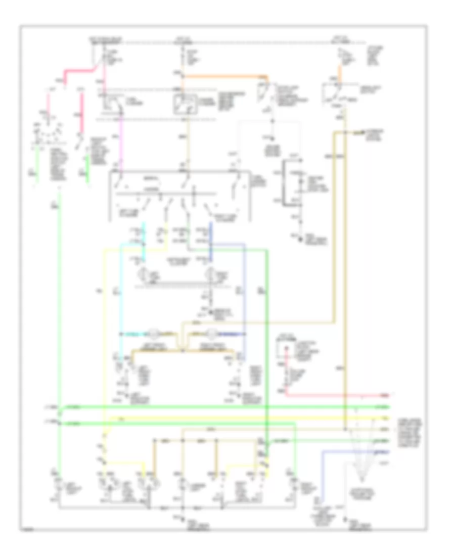
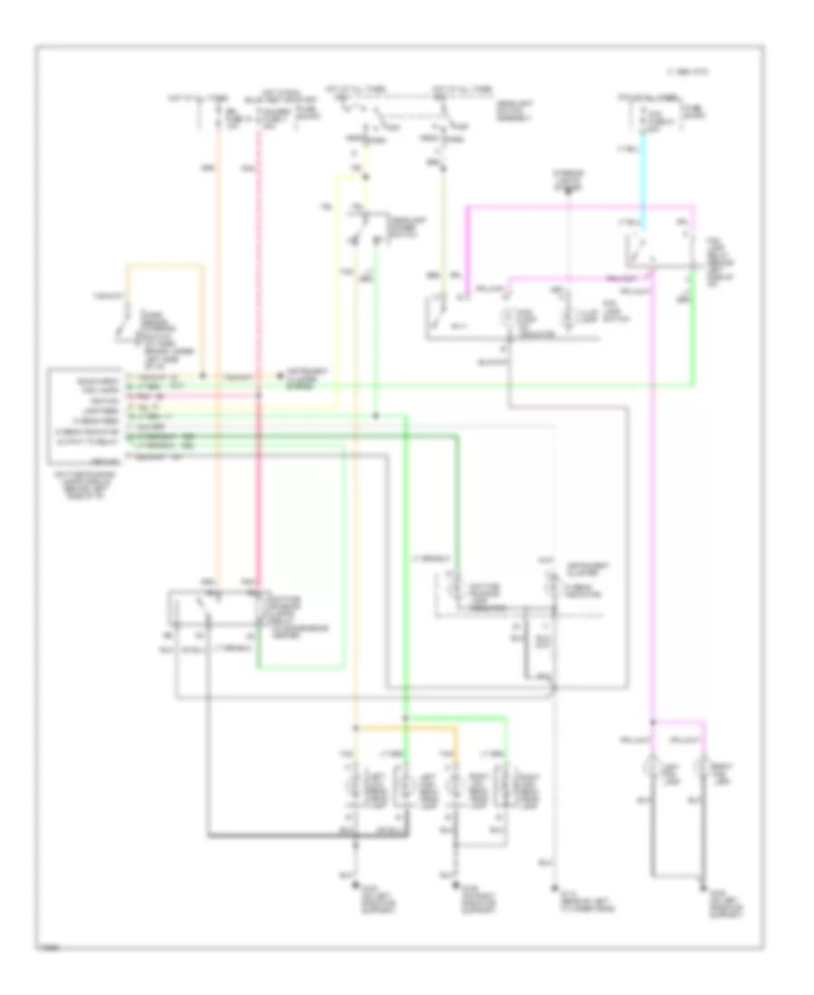
Headlight Wiring Diagram, Composite with DRL for GMC Jimmy 1995
List of elements for Headlight Wiring Diagram, Composite with DRL for GMC Jimmy 1995:
- Bulb check
- C 1995 vftc
- Daytime running lamp indicator
- Daytime running lamps module (behind left side of i/p)
- Daytime running lamps relay (in convenience center)
- Drl fuse 15 10a
- Fog lamp on indicator
- Fog fuse 21 20a
- Fog lamp relay (behind left side of i/p)
- Fog lamp switch
- Fog lamps
- Fuse block
- G108 (on left radiator support)
- G109 (on right radiator support)
- G114 (rear of left cylinder head)
- Gauges fuse 4 20a
- Ground
- Head
- Headlamp dimmer switch
- Headlight switch assembly
- Hi beam feed
- Hi beam indicator
- Hot at all times
- Hot in run, bulb test or start
- Ignition
- Illum lamp
- Instrument cluster
- Instrument cluster system
- Interior lights system
- Lamp feed
- Left fog lamp
- Left high beam head- lamp
- Left low beam head- lamp
- Off
- Output to relay
- Park
- Park brake warning switch (at park brake, under left side of i/p)
- Pnk
- Right fog lamp
- Right high beam head- lamp
- Right low beam head- lamp
- Tan
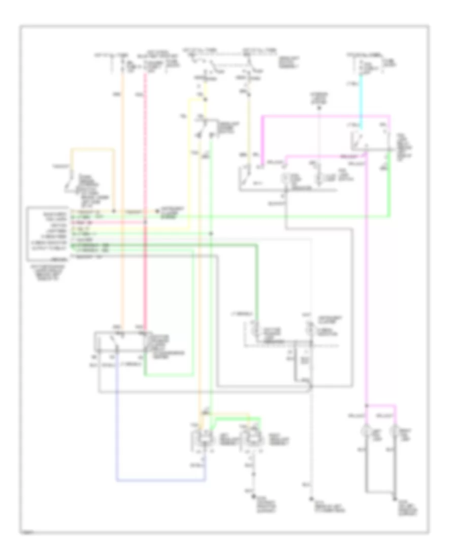
Headlight Wiring Diagram, Sealed Beam with DRL for GMC Jimmy 1995
List of elements for Headlight Wiring Diagram, Sealed Beam with DRL for GMC Jimmy 1995:
- Bulb check
- Daytime running lamp indicator
- Daytime running lamps module (behind left side of i/p)
- Daytime running lamps relay (in convenience center)
- Drl fuse 15 10a
- Fog lamp on indicator
- Fog fuse 21 20a
- Fog lamp relay (behind left side of i/p)
- Fog lamp switch
- Fog lamps
- Fuse block
- G108 (on left radiator support)
- G109 (on right radiator support)
- G114 (rear of left cylinder head)
- Gauges fuse 4 20a
- Ground
- Head
- Headlamp dimmer switch
- Headlight switch assembly
- Hi beam feed
- Hi beam indicator
- Hot at all times
- Hot in run, bulb test or start
- Ignition
- Illum lamp
- Instrument cluster
- Instrument cluster system
- Interior lights system
- Lamp feed
- Left fog lamp
- Left headlamp assembly
- Off
- Output to relay
- Park
- Park brake warning switch (at park brake, under left side of i/p)
- Pnk
- Right fog lamp
- Right headlamp assembly
- Tan
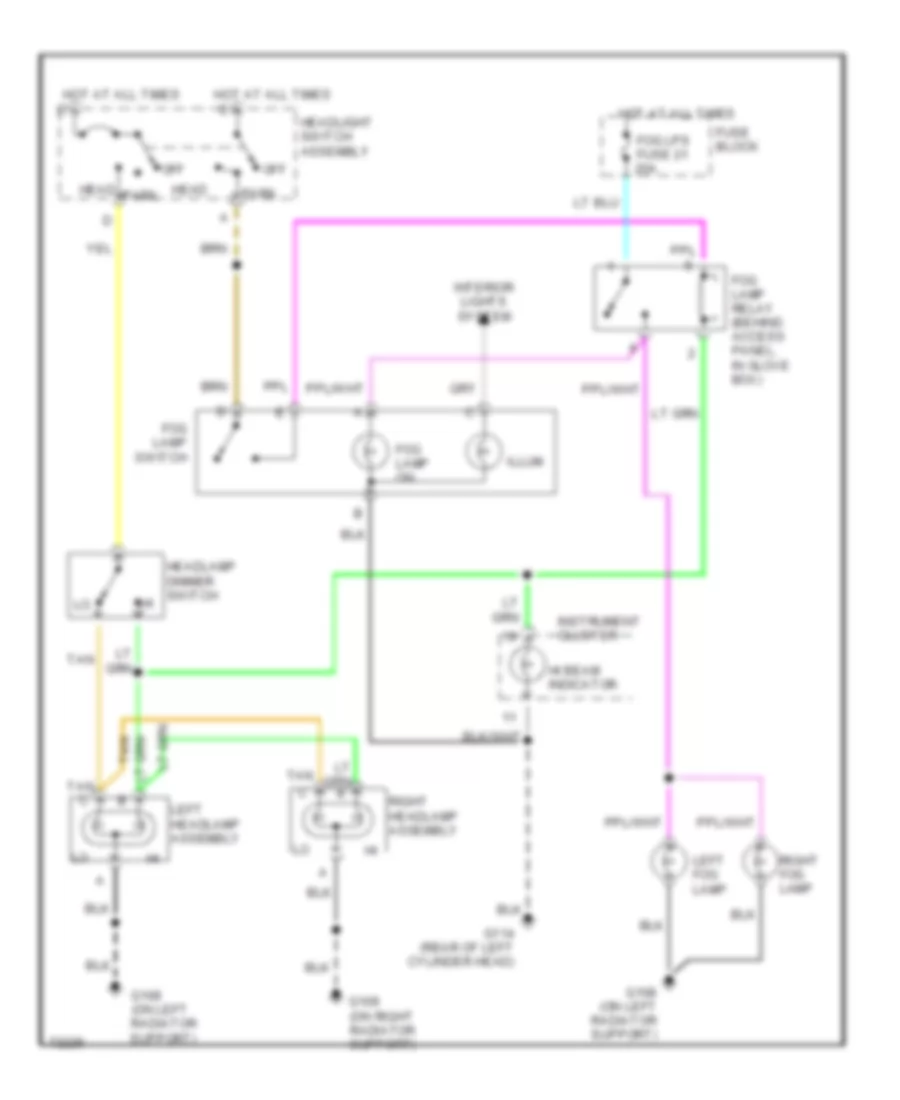
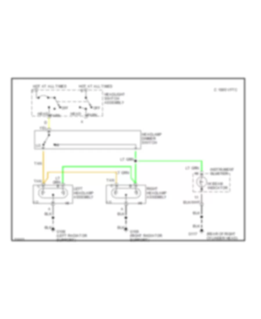
Headlight Wiring Diagram, Sealed Beam without DRL for GMC Jimmy 1995
List of elements for Headlight Wiring Diagram, Sealed Beam without DRL for GMC Jimmy 1995:
- (rear of right cylinder head)
- C 1995 vftc
- G108 (left radiator support)
- G109 (right radiator support)
- G117
- Head
- Headlamp dimmer switch
- Headlight switch assembly
- Hi beam indicator
- Hot at all times
- Instrument cluster
- Left headlamp assembly
- Off
- Park
- Right headlamp assembly
- Tan
HORN
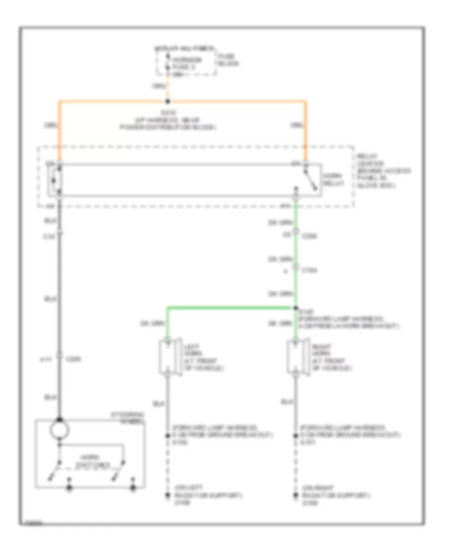
Horn Wiring Diagram for GMC Jimmy 1995
List of elements for Horn Wiring Diagram for GMC Jimmy 1995:
- (forward lamp harness, 6 cm from ground breakout) s150
- (forward lamp harness, 6 cm from ground breakout) s151
- (on left radiator support) g108
- (on right radiator support) g109
- A11
- C10
- C104
- C200
- C206
- Fuse block
- Horn
- Horn relay
- Horn/dm fuse 2 20a
- Hot at all times
- Left horn (at front of vehicle)
- Relay center (behind access panel in glove box)
- Right horn (at front of vehicle)
- S145 (forward lamp harness, 4 cm from lh horn breakout)
- S210 (i/p harness, near power distribution block)
- Steering wheel
- Switches
INSTRUMENT CLUSTER
Brake Warning Wiring Diagram for GMC Jimmy 1995
List of elements for Brake Warning Wiring Diagram for GMC Jimmy 1995:
- (left i/p)
- (left side eng compt)
- (rear of right cylinder head)
- A/t
- Brake pressure modulator valve
- Brake pressure warning switch (left rear eng compt)
- Daytime running lamps module (left i/p)
- Diode module
- From instrument cluster circuit
- G117
- Ignition switch (closed in start)
- M/t
- Nca
- Park brake warning switch (at park brake pedal)
- Rear window release solenoid (top center of endgate)
- Vehicle control module (right side eng compt)
- W/ drl
- W/ pcm
- W/ vcm
- W/o drl
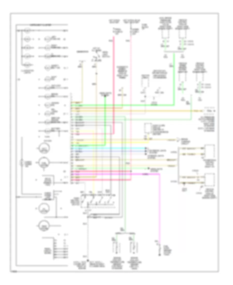
Instrument Cluster Wiring Diagram for GMC Jimmy 1995
List of elements for Instrument Cluster Wiring Diagram for GMC Jimmy 1995:
- (4 cyl.)
- (6 cyl.)
- (6 cyl.-top rear of engine)
- (above right valve cover)
- (vin w)
- (vin z)
- 4 cyl.
- 4wal brake pressure modulator valve (right side engine compt)
- 510 ohm
- 6 cyl.
- Air bag ind.
- Antilock ind.
- Audio alarm module (center i/p, in convenience center)
- Battery ind.
- Brake ind.
- Brake warning circuit
- Check gages ind.
- Check gages lamp driver
- Diagnostic energy reserve module (right kick panel)
- Drl lamps ind.
- Engine coolant temperature sender (left cyl. head)
- Engine coolant temperature sensor (top front of engine)
- Exterior lights system
- Fuel gauge
- Fuel pump/ sender (in fuel tank)
- Fuse block: i/p
- G110 (lower left front of engine)
- G117 (rear of right cylinder head)
- Gages fuse 4 20a
- Generator
- Head-
- Headlights
- Headlights system
- Hi beam ind.
- Hot at all times
- Hot in run or start
- Hot in run, bulb test or start
- Ignition coil
- Ignition coil driver module
- Illumination lights
- Instrument cluster
- Interior lights system
- Left turn ind.
- Light switch
- Off
- Oil gauge
- Oil pressure switch/sender (4 cyl.-lower right side of engine)
- Park/ neutral position switch
- Pnk
- Powertrain control module (right i/p)
- Prndl circuit board
- Prndl fuse 24 10a
- Right turn ind.
- Safety belt ind.
- Service engine soon ind.
- Shift ind.
- Solid state speedo/ tach
- System
- Tan
- Temp gauge
- Vehicle control module (right side engine compt)
- Vehicle speed sensor buffer (right i/p)
- Vin w w/vcm
- Vin z only
- Volt meter
- W/ pcm
- W/ vcm
- W/drl
- W/pcm
- W/vcm
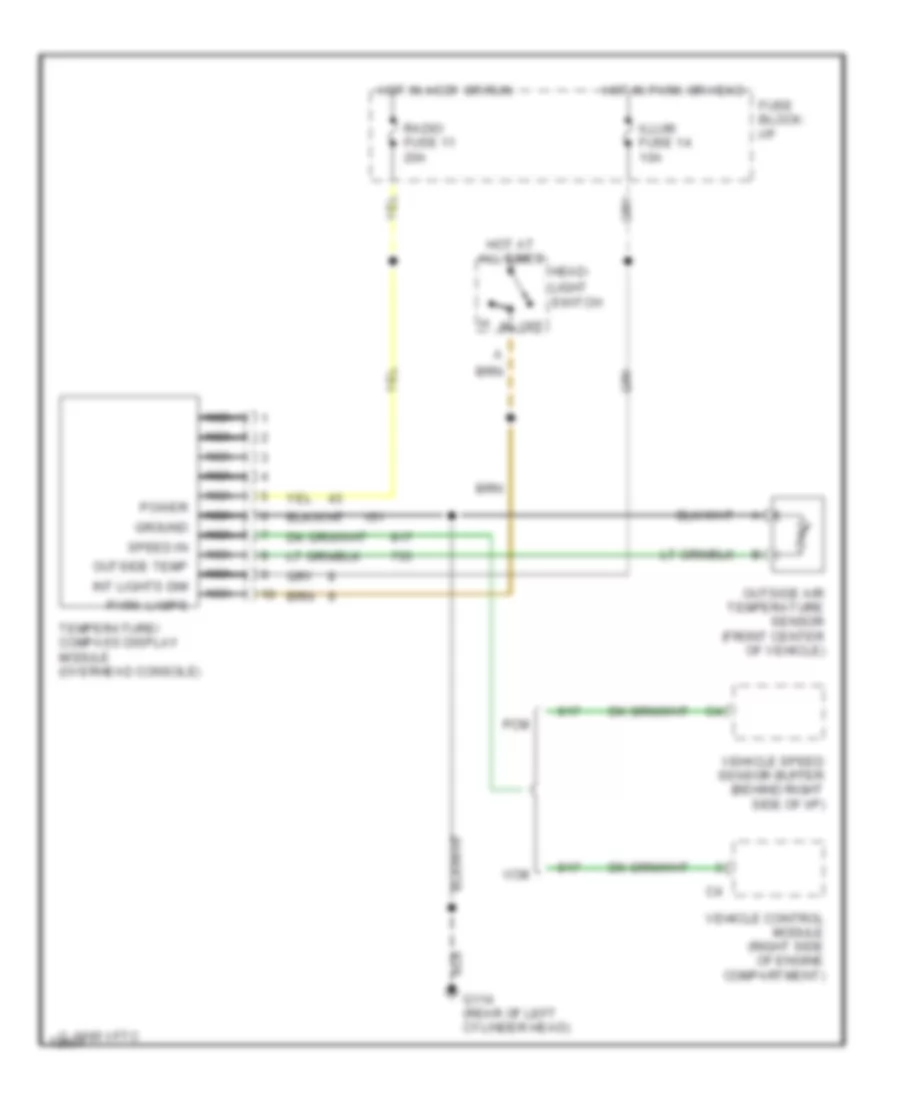
Overhead Console Wiring Diagram for GMC Jimmy 1995
List of elements for Overhead Console Wiring Diagram for GMC Jimmy 1995:
- 1995 vftc c
- Fuse block: i/p
- G114 (rear of left cylinder head)
- Ground
- Head-
- Hot at all times
- Hot in accy or run
- Hot in park or head
- Illum fuse 14 10a
- Int lights dim
- Light switch
- Nca
- Off
- Outside air temperature sensor (front center of vehicle)
- Outside temp
- Park lamps
- Pcm
- Power
- Radio fuse 11 20a
- Speed in
- Temperature/ compass display module (overhead console)
- Vcm
- Vehicle control module (right side of engine compartment)
- Vehicle speed sensor buffer (behind right side of i/p)
INTERIOR LIGHTS
Courtesy Lamps Wiring Diagram for GMC Jimmy 1995
List of elements for Courtesy Lamps Wiring Diagram for GMC Jimmy 1995:
- (4 door)
- (left rear frame rail)
- (lower center of i/p)
- Courtesy switch
- Dome lamp
- Fuse block: i/p
- G112 (left side
- G415
- Gauges fuse 4 20a
- Headlamp switch
- Horn/dm fuse 2 20a
- Hot at all times
- Hot in run or accy
- Hot in run, bulb
- I/p courtesy box lamp
- I/p dimmer switch
- Inside rear view mirror & lamp
- Inside rearview mirror lamps
- Interior lamp control module
- Keyless entry module
- Left door handle switch
- Left front door jamb switch
- Left i/p courtesy lamp
- Left rear door jamb switch
- Left vanity mirror lamp
- Map lamps
- Of engine)
- Park lps fuse 3 20a
- Pnk
- Radio fuse 11 20a
- Rear dome lamp & switch
- Right door handle switch
- Right front door jamb switch
- Right i/p courtesy lamp
- Right rear door jamb switch (4 door)
- Right vanity mirror lamp
- Solid state
- Test or start
- Under- hood lamp
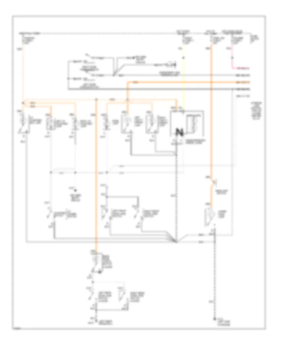
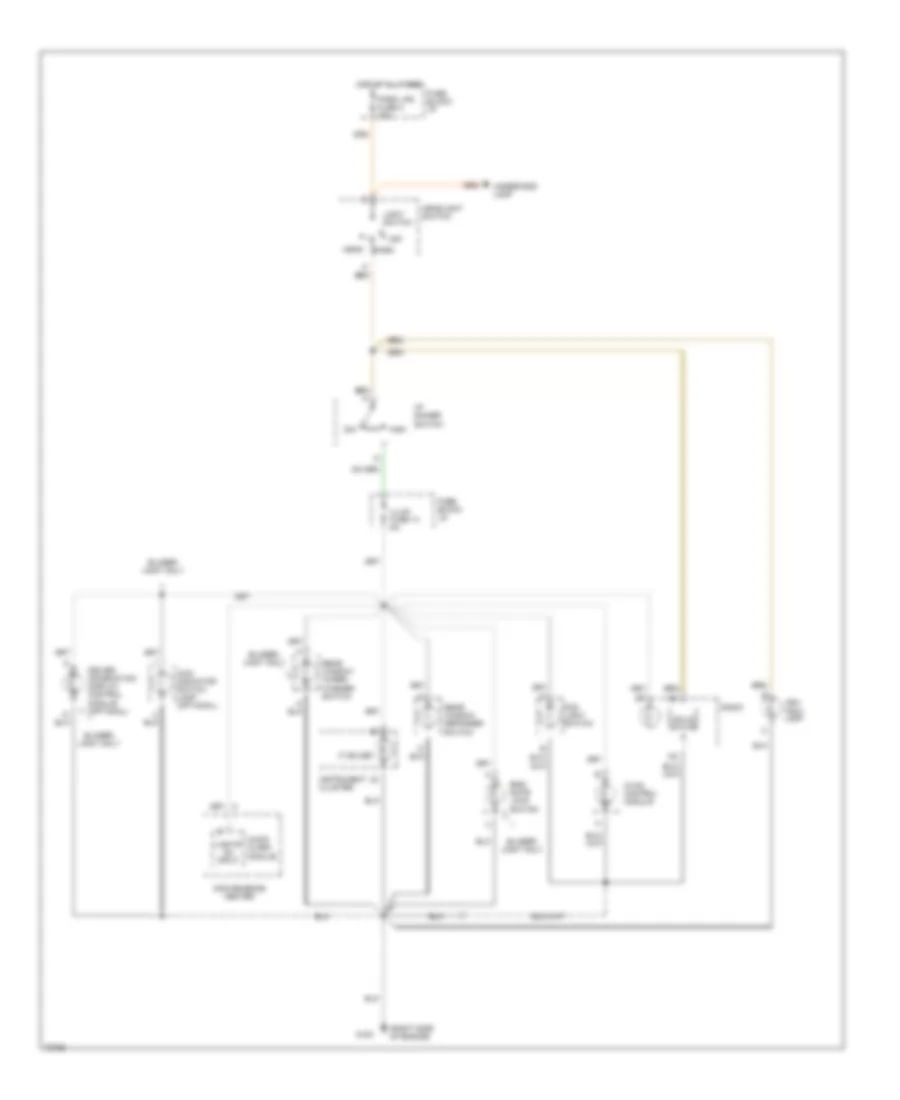
Instrument Illumination Wiring Diagram for GMC Jimmy 1995
List of elements for Instrument Illumination Wiring Diagram for GMC Jimmy 1995:
- (7) bulbs
- (right side of engine)
- 4wd indicator switch lamp (optional)
- Ash tray lamp
- Audio alarm module
- Blazer/ jimmy only
- Center
- Convenience
- Dim
- Driver information display control module (optional)
- End- gate lock switch
- Fog light switch
- Fuse block: i/p
- G120
- Head
- Headlight switch
- High
- Hot at all times
- Hvac control module
- I/p dimmer switch
- Illum fuse 14 5a
- Instrument cluster
- Light switch
- Lights on input
- Off
- Park
- Park lps fuse 3 20a
- Radio
- Rear window defogger switch
- Rear window wiper/ washer switch
- Solid state
- Underhood lamp
POWER DISTRIBUTION
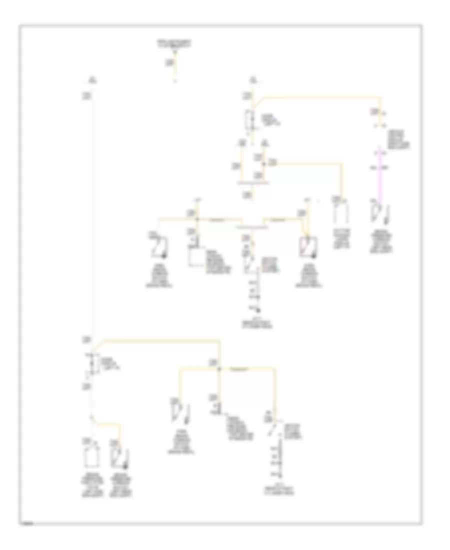
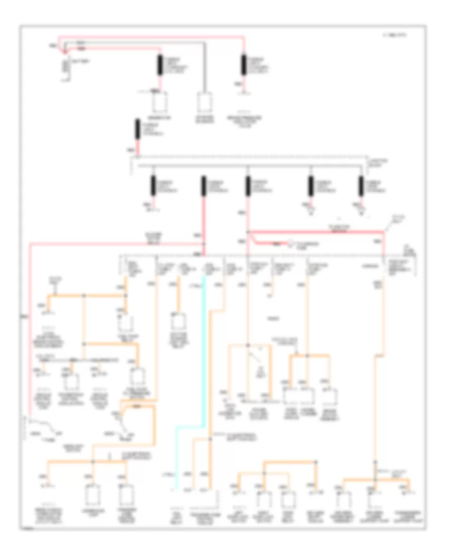
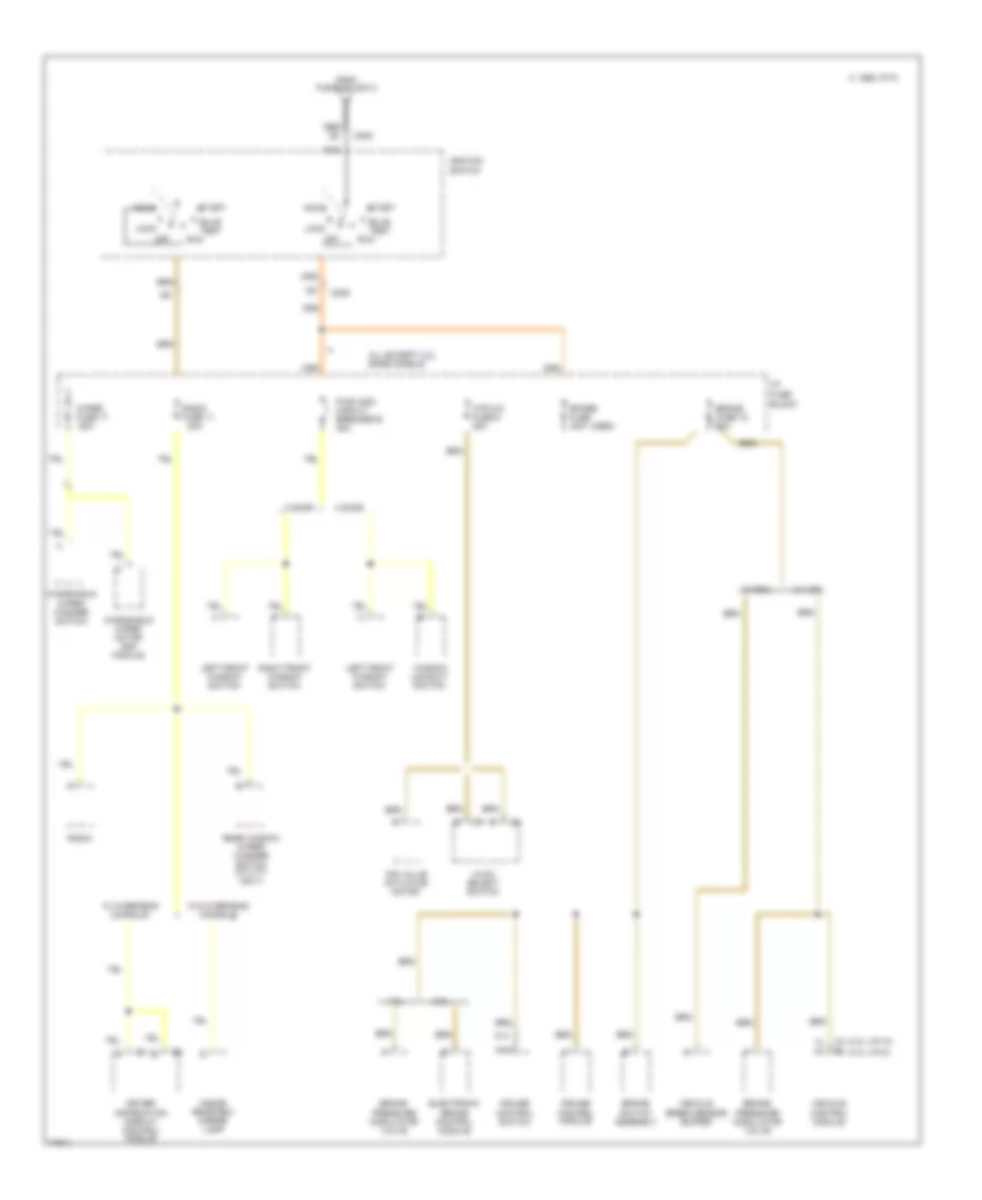
Power Distribution Wiring Diagram (1 of 4) for GMC Jimmy 1995
List of elements for Power Distribution Wiring Diagram (1 of 4) for GMC Jimmy 1995:
- 2 wal electronic brake control module (ebcm)
- 4.3l vin w (vcm)
- 4.3l vin z (vcm)
- 4wd fuse 19 20a
- Audio alarm module
- Battery
- Blower motor relay
- Brake pressure modulator valve
- Brake switch assembly
- C 1995 vftc
- D14
- D15
- Data link connector (dlc)
- Daytime running light (drl) relay
- Door lock relay
- Driver's lumbar support pump
- Driver's power seat assembly
- Drl fuse 15 10a
- E16
- Ecm batt fuse 9 15a
- Fog fuse 21 20a
- Fog light relay
- Fuel pump oil pressure switch
- Fuel pump relay
- Fusible link g (12 ga-rust) (4.3l vin z)
- Generator
- Hazard flasher
- Head
- Headlight switch
- Horn/dm
- I/p fuse block
- Junction block
- Keyless entry module
- Left door lock switch
- Off
- Park
- Passenger's lumbar support pump
- Pcm
- Power auxiliary outlets
- Powertrain control module (pcm)
- Pwr accy circuit breaker a 20a
- Pwr aux fuse 7 25a
- Radio
- Rdo batt fuse 13 10a
- Rear window wiper motor and module (utility only)
- Red
- Red red
- Right door lock switch
- Starter solenoid
- Stop-haz fuse 1 20a
- T/l ctsy fuse 3 20a
- To horn/dm fuse
- To ignition switch
- Transfer case control module
- Underhood lamp
- Utility only
- Vehicle control module (vcm)
- W/ 2.2l only
- W/ 4.3l only
- W/ electronic shift 4wd only
- W/o 4.3l vin z (vcm) only
Power Distribution Wiring Diagram (2 of 4) for GMC Jimmy 1995
List of elements for Power Distribution Wiring Diagram (2 of 4) for GMC Jimmy 1995:
- (4.3l vin w)
- (4.3l vin z)
- 2 door
- 2.2l
- 20a
- 4 door
- 4.3l
- A13
- Accy
- Air valve actuator motor
- All except 2.2l base models
- Block
- Brake fuse 18 20a
- Brake pressure modulator valve
- Brake switch assembly
- Bulb test
- C 1995 vftc
- C205
- C206
- Cruise control module
- Cruise control switch
- Driver information display control module
- Electronic brake control module
- From fusible link c
- Htr a/c fuse 6 25a
- Hvac select switch
- I/p fuse
- Ignition
- Inside rearview mirror lamp
- Left front window switch
- Lock
- Nca
- Off
- Pwr wdo circuit breaker b 30a
- Radio
- Radio fuse 11
- Rear window wiper/ washer switch (utility only)
- Red d2
- Right front window switch
- Run
- Spare fuse (not used)
- Start
- Switch
- Vehicle control module
- Vehicle speed sensor buffer
- W/ overhead console
- W/ pcm
- W/ vcm
- W/o overhead console
- Window lockout switch
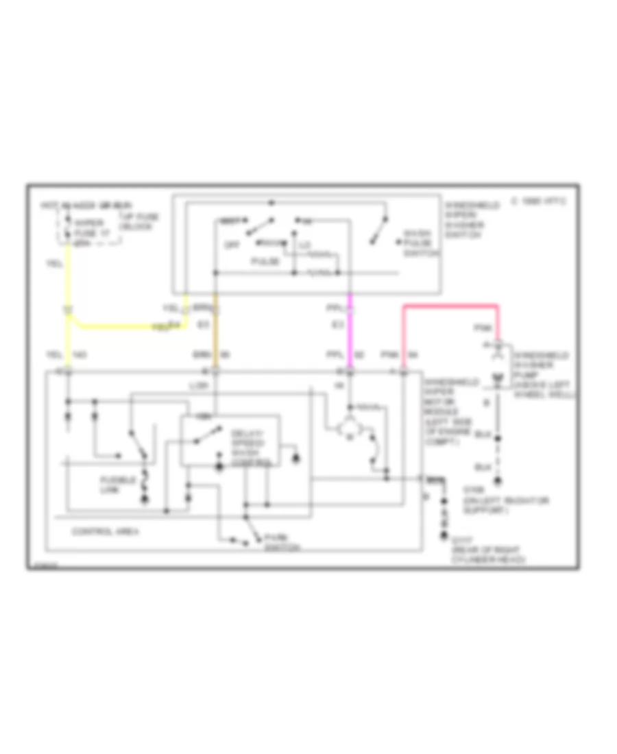
- Windshield wiper motor and module
- Windshield wiper/ washer switch
- Wiper fuse 17 25a
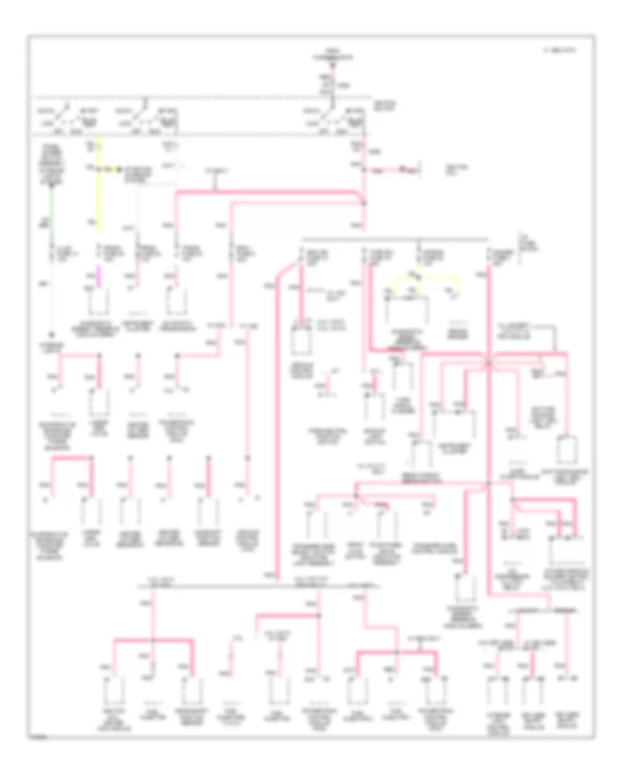
Power Distribution Wiring Diagram (3 of 4) for GMC Jimmy 1995
List of elements for Power Distribution Wiring Diagram (3 of 4) for GMC Jimmy 1995:
- (4.3l vin w only)
- (4.3l vin z) (4.3l vin w)
- (interior lights system)
- (vcm) (pcm)
- 2.2l
- 4.3l vin w w/
- 4.3l vin w w/ pcm
- 4.3l vin w w/ vcm
- 4.3l vin z
- A/c compressor clutch relay
- A/t
- A/t only
- A10
- Accy
- Air bag fuse 22 10a
- All except utility w/ pcm module
- Arming sensor
- Audio alarm module
- Automatic transmission
- B10
- Backup light switch
- Bulb test
- C 1995 vftc
- C205
- C206
- Camshaft position sensor
- Crank fuse 20 10a
- Crankshaft position sensor
- Daytime running light (drl) module
- Daytime running light (drl) relay
- Diagnostic energy reserve module (derm)
- Diagnostic enrgy reserve module (derm)
- E15
- Ecm ign fuse 10 20a
- Eng 1 fuse 5 20a
- Entry
- Evaporative emissions canister purge solenoid
- F15
- Four-wheel drive indicator assembly
- From
- Front axle switch
- Fuel injector
- Fuel injector 1
- Fuel injector 2
- Fuel injectors (1,2,3,4)
- Fusible link b
- Gauges fuse 4 20a
- Heated oxygen sensor
- Heated oxygen sensor #1
- Heated oxygen sensor #2
- I/p fuse block
- Ignition coil
- Ignition coil driver (icd) module
- Ignition switch
- Illum fuse 14 10a
- Instrument cluster
- Intake manifold runner control valve relay
- Interior light control module
- Interior lights
- Keyless entry module
- Linear egr valve
- Lock
- M/t
- Nca
- Off
- Panel dimmer switch assembly
- Park/neutral position switch
- Pcm or 2.2l
- Pickup
- Pnk
- Pnk c5
- Pnk c6
- Pnk e
- Powertrain control module (pcm)
- Prndl fuse 24 10a
- Rear window defog switch
- Red
- Run
- Start
- Starting/ charging system
- Trans fuse 23 10a
- Transfer case control module
- Transfer case select switch/ indicator lamp assembly
- Turn b/u fuse 16 15a
- Turn signal flasher
- Utility
- Vehicle control module
- Vehicle control module (vcm)
- W/ keyless
- W/ pcm
- W/ pcm only
- W/ utility only
- W/ vcm
- W/ vcm only
- W/o keyless
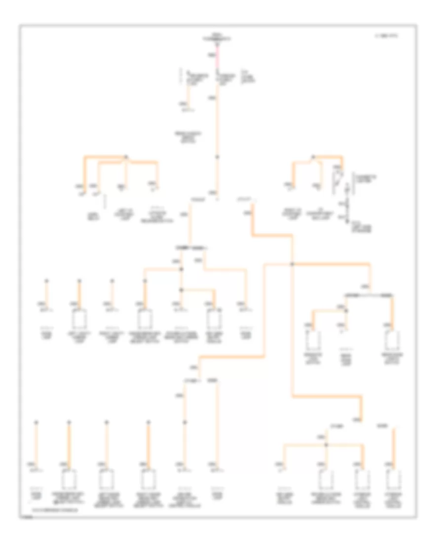
Power Distribution Wiring Diagram (4 of 4) for GMC Jimmy 1995
List of elements for Power Distribution Wiring Diagram (4 of 4) for GMC Jimmy 1995:
- Base
- C 1995 vftc
- Cigarette lighter
- Dome lamp
- Driver information display control module
- Endgate lock switch
- From fusible link d
- G112 (left side of engine)
- Horn relay
- Horn/dm fuse 2 20a
- I/p compartment box lamp
- I/p fuse block
- Inside rearview mirror lamp select switch
- Interior light control module
- Keyless entry module
- Left i/p courtesy lamp
- Left inside rearview mirror lamp select switch
- Left vanity mirror lamp
- Liftgate glass release switch
- Other
- Pickup
- Power outside rearview mirror switch
- Rear dome lamp
- Rear dome lamp & switch
- Rear window defog switch
- Red
- Right i/p courtesy lamp
- Right inside rearview mirror lamp select switch
- Right vanity mirror lamp
- Rr defog fuse 8 30a
- Utility
- W/o overhead console
POWER DOOR LOCKS
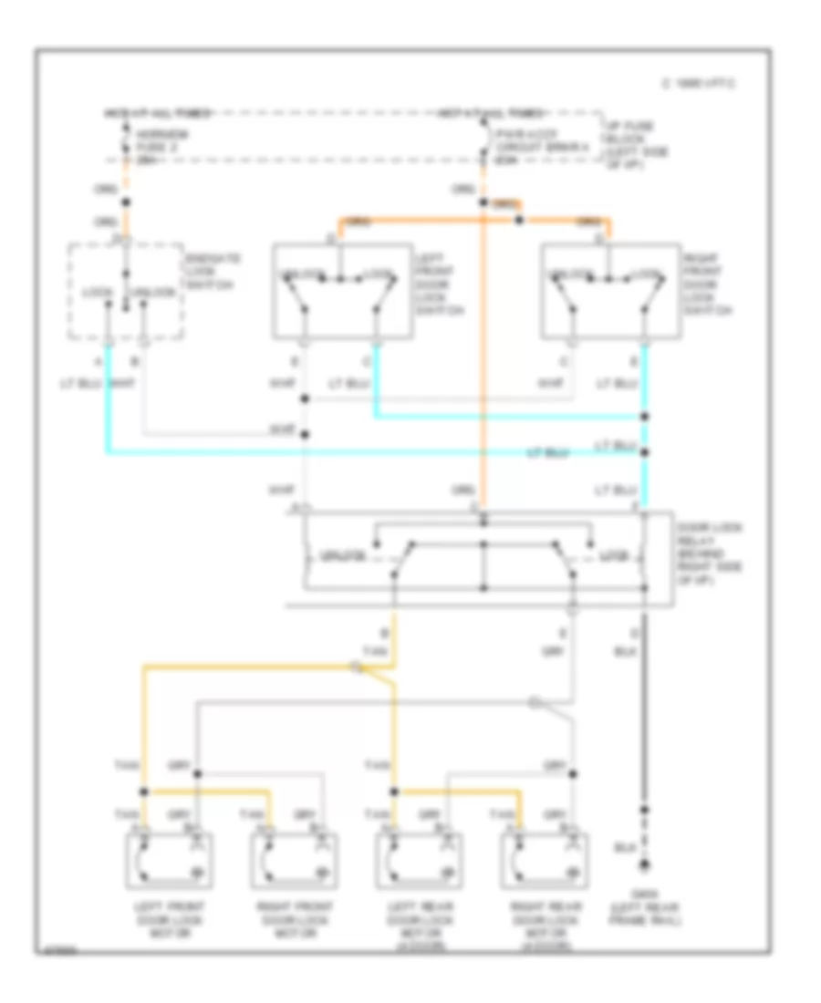
Door Lock Wiring Diagram for GMC Jimmy 1995
List of elements for Door Lock Wiring Diagram for GMC Jimmy 1995:
- C 1995 vftc
- Door lock relay (behind right side of i/p)
- Endgate lock switch
- G404 (left rear frame rail)
- Horn/dm fuse 2 20a
- Hot at all times
- I/p fuse block (left side of i/p)
- Left front door lock motor
- Left front door lock switch
- Left rear door lock motor (4 door)
- Lock
- Pwr accy circuit brkr a 20a
- Right front door lock motor
- Right front door lock switch
- Right rear door lock motor (4 door)
- Tan
- Tan a
- Unlock
Keyless Entry Wiring Diagram, 2 Door for GMC Jimmy 1995
List of elements for Keyless Entry Wiring Diagram, 2 Door for GMC Jimmy 1995:
- Batt
- C 1995 vftc
- Door lock relay (behind right side of i/p)
- G115 (rear of cylinder head)
- G404 (left rear frame rail)
- Gauges fuse 4 20a
- Ground
- Horn/dm fuse 2 20a
- Hot at all times
- Hot in run, bulb test or start
- Hush panel)
- I/p fuse block (left side of i/p)
- Ignition
- Illum out
- Interior lights system
- Jamb sw in
- Keyless entry module (behind left hush panel)
- Keyless entry programming connector (behind left
- Left door jamb switch
- Left front door lock motor
- Left front door lock switch
- Lf unlck out
- Lock
- Lock output
- Lock relay
- Pnk
- Prgrm enable
- Pwr accy circuit breaker a 20a
- Right door jamb switch
- Right front door lock motor
- Right front door lock switch
- Tan
- Unlck output
- Unlock
- Unlock relay
Keyless Entry Wiring Diagram, 4 Door for GMC Jimmy 1995
List of elements for Keyless Entry Wiring Diagram, 4 Door for GMC Jimmy 1995:
- A/t
- Batt
- Cargo lamp switch
- Door hndl in
- Door lock relay (behind right side of i/p)
- Driver's door lock cylinder switch
- Endgate lock switch
- G115 (rear of cylinder head)
- G404 (left rear frame rail)
- Gauges fuse 4 20a
- Ground
- Horn/dm fuse 2 20a
- Hot at all times
- Hot in run, bulb test or start
- I/p dimmer switch
- I/p fuse block (left side of i/p)
- Ignition
- Interior lights system
- Jamb sw in
- Keyless entry module (behind left hush panel)
- Keyless entry programming conn (behind left hush panel)
- Left door handle switch
- Left front door jamb switch
- Left front door lock motor
- Left front door lock switch
- Left rear door jamb switch
- Left rear door lock motor
- Lf unlck out
- Lftgt release
- Lock
- Lock output
- Lock relay
- M/t
- Park brake switch (at brake pedal)
- Park/neutral position switch (left side of transmission)
- Pnk
- Prgrm enable
- Pwr accy circuit breaker a 20a
- Rear endgate door jamb switch
- Rear window release solenoid (top center of endgate)
- Rear window release switch
- Right door handle switch
- Right front door jamb switch
- Right front door lock motor
- Right front door lock switch
- Right rear door jamb switch
- Right rear door lock motor
- Tan
- Transfer case control module
- Unlck output
- Unlock
- Unlock relay
- W/o np1
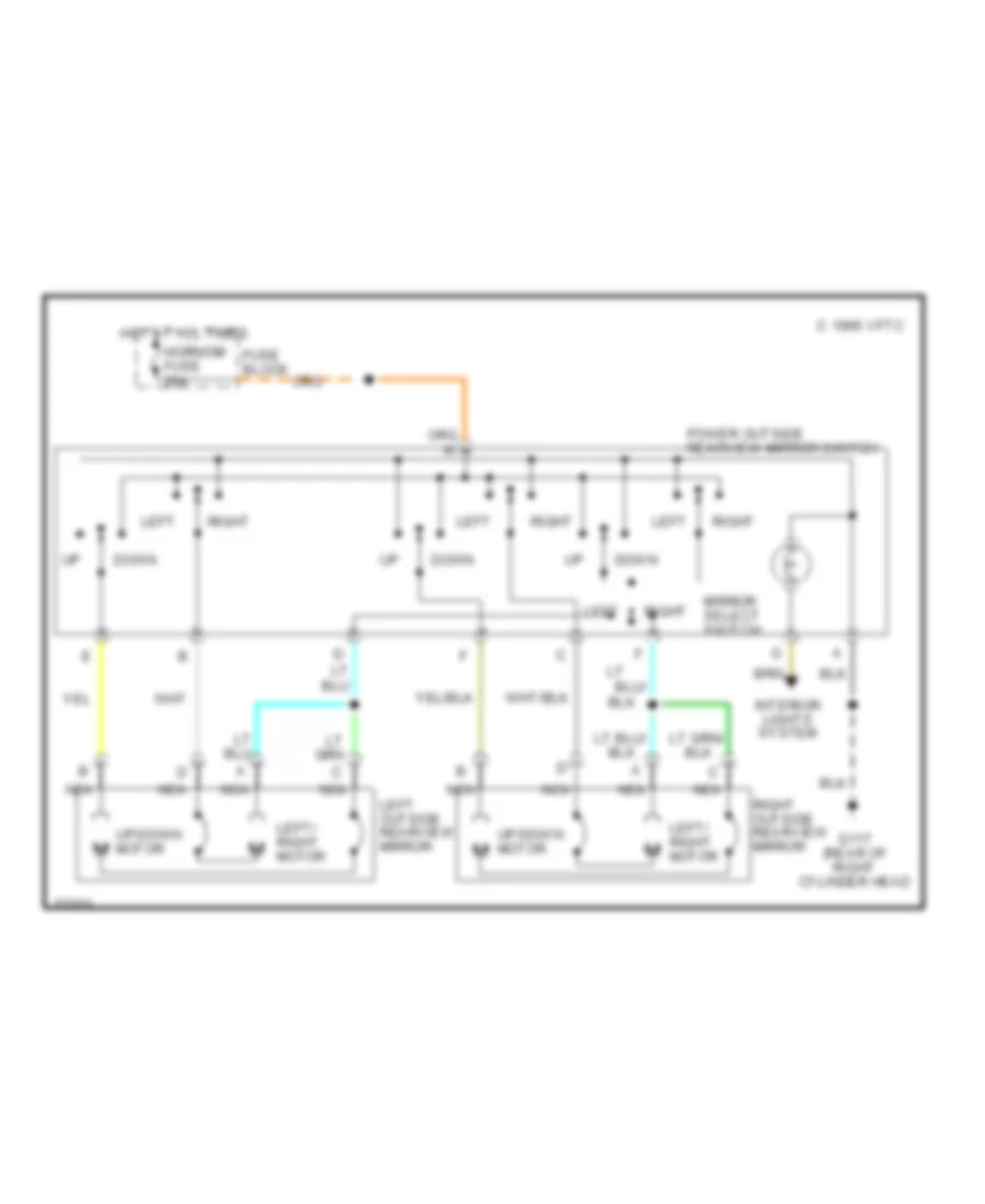
POWER MIRRORS
Power Mirror Wiring Diagram for GMC Jimmy 1995
List of elements for Power Mirror Wiring Diagram for GMC Jimmy 1995:
- C 1995 vftc
- D nca
- Down
- Fuse block
- G117 (rear of right cylinder head
- Horn/dm fuse 20a
- Hot at all times
- Interior lights system
- Left
- Left outside rearview mirror
- Left/ right motor
- Mirror select switch
- Nca
- Power outside rearview mirror switch
- Right
- Right outside rearview mirror
- Up/down motor
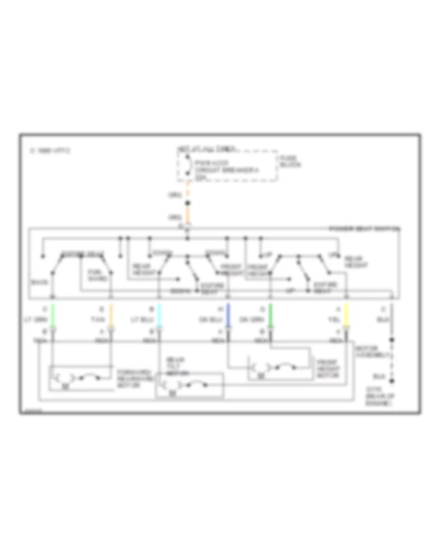
POWER SEATS
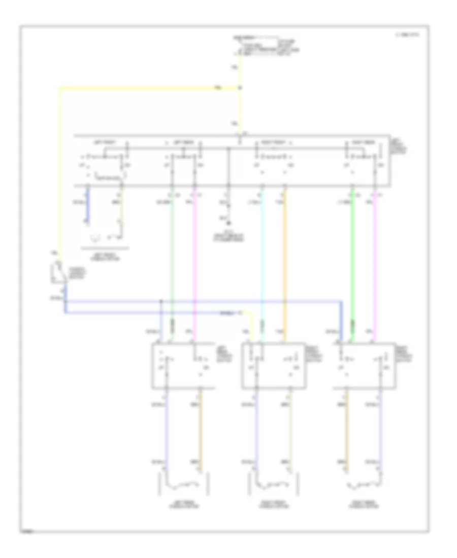
6-Way Power Seat Wiring Diagram for GMC Jimmy 1995
List of elements for 6-Way Power Seat Wiring Diagram for GMC Jimmy 1995:
- Back
- C 1995 vftc
- Down
- Entire seat
- For- ward
- Forward/ rearward motor
- Front height
- Front height motor
- Fuse block
- G115 (rear of engine)
- Hot at all times
- Motor assembly
- Nca
- Power seat switch
- Pwr accy circuit breaker a 20a
- Rear height
- Rear tilt motor
- Tan
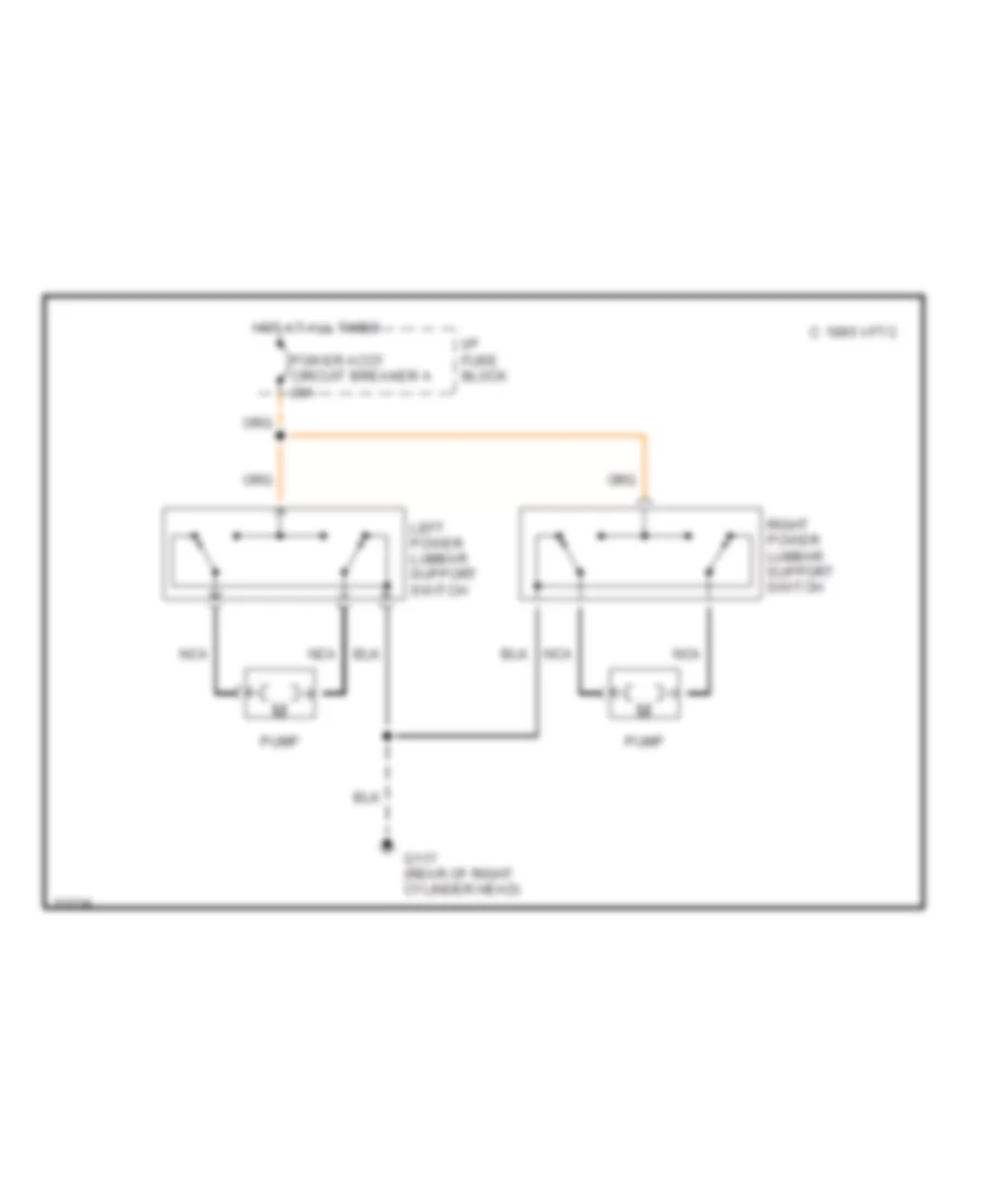
Lumbar Wiring Diagram for GMC Jimmy 1995
List of elements for Lumbar Wiring Diagram for GMC Jimmy 1995:
- C 1995 vftc
- G117 (rear of right cylinder head)
- Hot at all times
- I/p fuse block
- Left power lumbar support switch
- Nca
- Power accy circuit breaker a 20a
- Pump
- Right power lumbar support switch
POWER WINDOWS
Power Window Wiring Diagram, 2 Door for GMC Jimmy 1995
List of elements for Power Window Wiring Diagram, 2 Door for GMC Jimmy 1995:
- C 1995 vftc
- Exp dn mod
- G117 (right rear of cylinder head)
- Hot in run
- I/p fuse block (left side of i/p)
- Left front
- Left front window motor
- Left front window switch
- Pwr wdo circuit breaker 30a
- Right front
- Right front window motor
- Right front window switch
- Tan
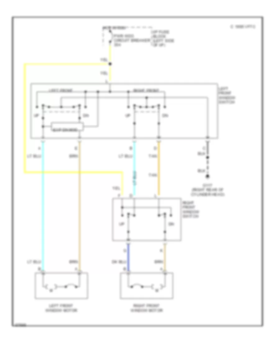
Power Window Wiring Diagram, 4 Door for GMC Jimmy 1995
List of elements for Power Window Wiring Diagram, 4 Door for GMC Jimmy 1995:
- C 1995 vftc
- Exp dn mod
- G117 (right rear of cylinder head)
- Hot in run
- I/p fuse block (left side of i/p)
- Left front
- Left front window motor
- Left front window switch
- Left rear
- Left rear window motor
- Left rear window switch
- Pwr wdo circuit breaker 30a
- Right front
- Right front window motor
- Right front window switch
- Right rear
- Right rear window motor
- Right rear window switch
- Tan
- Window lockout switch
RADIO
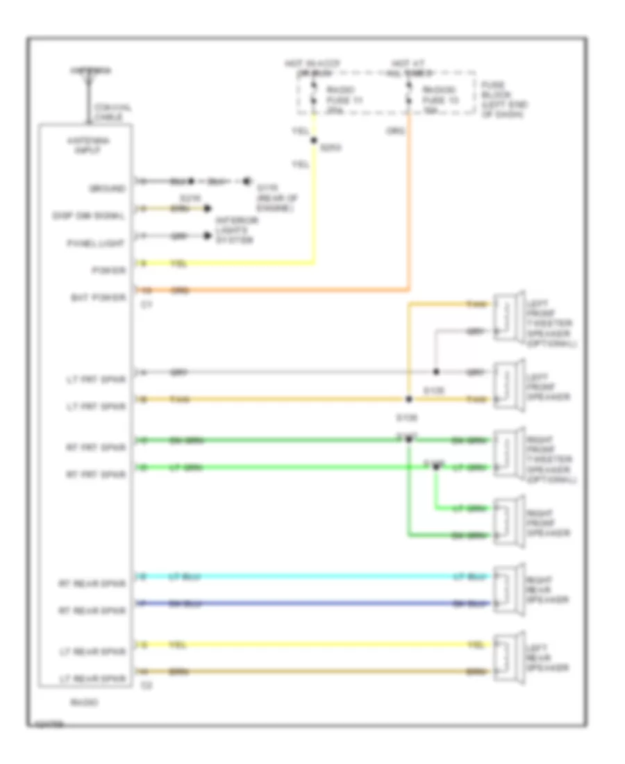
Radio Wiring Diagrams for GMC Jimmy 1995
List of elements for Radio Wiring Diagrams for GMC Jimmy 1995:
- Antenna
- Antenna input
- Bat power
- Coaxial cable
- Disp dim signal
- Fuse block (left end of dash)
- G115 (rear of engine)
- Ground
- Hot at all times
- Hot in accy or run
- Interior lights system
- Left front speaker
- Left front tweeter speaker (optional)
- Left rear speaker
- Lt frt spkr
- Lt rear spkr
- Panel light
- Power
- Radio
- Radio fuse 11 20a
- Radioo fuse 13 10a
- Right front speaker
- Right front tweeter speaker (optional)
- Right rear speaker
- Rt frt spkr
- Rt rear spkr
- S135
- S136
- S137
- S138
- S216
- S250
- Tan
STARTING/CHARGING
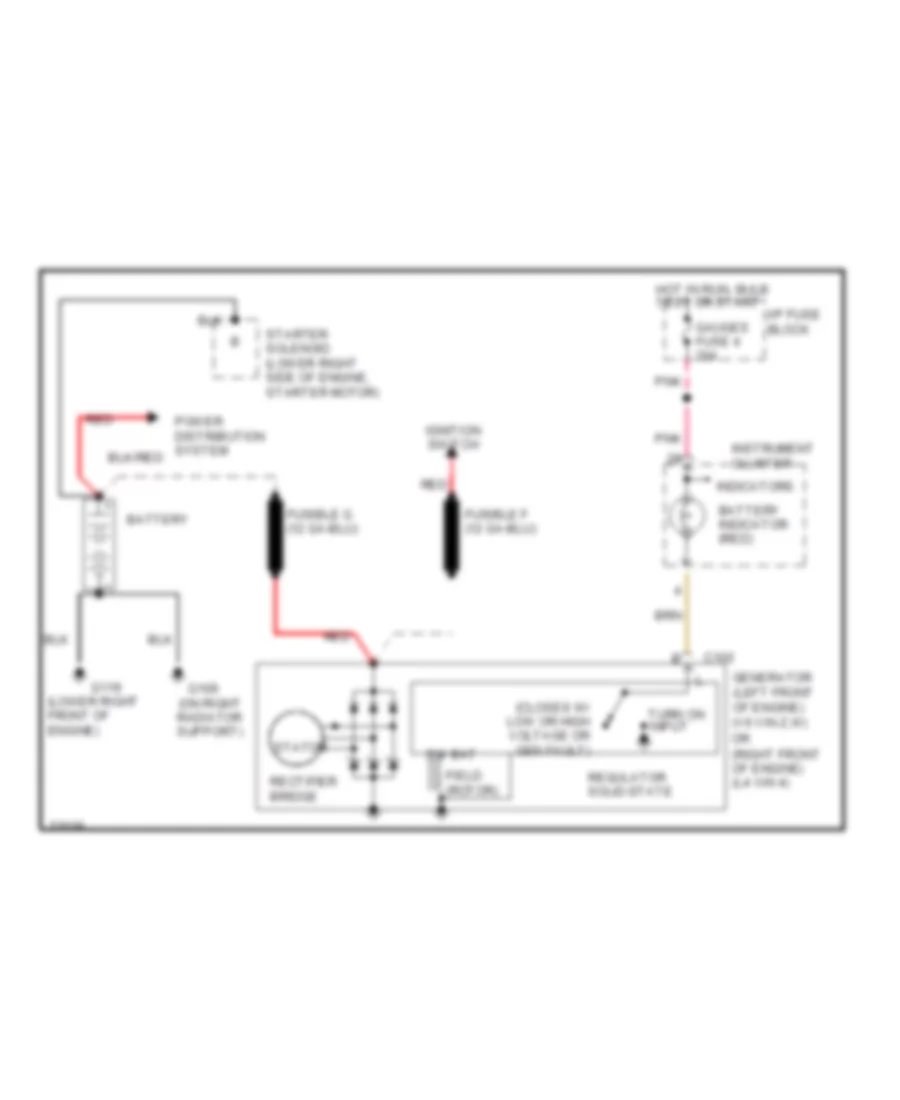
Charging Wiring Diagram for GMC Jimmy 1995
List of elements for Charging Wiring Diagram for GMC Jimmy 1995:
- (closes w/ low or high voltage or gen fault)
- (lower right front of engine)
- (on right radiator support)
- (right front of engine) (l4 vin 4)
- Battery
- Battery indicator (red)
- C102
- Field (rotor)
- G109
- G119
- Gauges fuse 4 20a
- Generator (left front of engine) (v6 vin z,w)
- Hot in run, bulb test or start
- I/p fuse block
- Ignition switch
- Indicators
- Instrument cluster
- Or
- Pnk
- Rectifier bridge
- Red
- Regulator solid-state
- Starter solenoid (lower right side of engine, starter motor)
- Stator
- Sw bat
- Turn on input
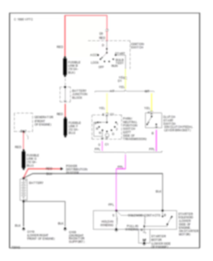
Starting Wiring Diagram for GMC Jimmy 1995
List of elements for Starting Wiring Diagram for GMC Jimmy 1995:
- (front of engine)
- (lower side of engine)
- (lower side of engine, on starter motor)
- A/t
- Accy
- B solenoid contacts
- Bat
- Battery
- Battery junction block
- Bulb test
- C 1995 vftc
- Clutch start switch (on clutch pedal lever bracket)
- G109 (on right radiator support)
- G119 (lower right front of engine)
- Generator
- Hold-in winding
- Ignition switch
- Lock
- M/t
- Off
- Park/ neutral position switch (left side of transmission)
- Power distribution system
- Pull-in winding
- Red
- Run
- Start
- Starter motor
- Starter solenoid
SUPPLEMENTAL RESTRAINTS
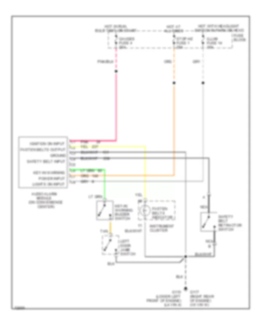
Supplemental Restraint Wiring Diagram for GMC Jimmy 1995
List of elements for Supplemental Restraint Wiring Diagram for GMC Jimmy 1995:
- A10
- A11
- A12
- Air bag fuse 22 10a
- Air bag warning lamp
- Arming sensor (left side frame rail, near center crossmember)
- B10
- B11
- B12
- C 1995 vftc
- Crank fuse 20 10a
- Data link connector (behind left side of i/p)
- Diagnostic energy reserve module (derm) (behind right kick panel)
- G105 (right front frame rail)
- G117 (rear of right cylinder head)
- G123 (right side of bulkhead)
- Gauges fuse 4 20a
- Hot in run, bulb test or start
- Hot in start
- I/p fuse block
- Instrument cluster
- Left hand forward discriminating sensor (left side of lower radiator support)
- Nca
- Pnk
- Powertrain control module (behind right side of i/p)
- Right hand forward discriminating sensor (right side of lower radiator support)
- Safety belt switch (left seat buckle)
- Shorting bar
- Sir coil assembly (top of steering column)
- Steering wheel inflator module (mounted on steering wheel)
- Tan
- Warning systems (audio alarm)
TRANSMISSION
4.3L
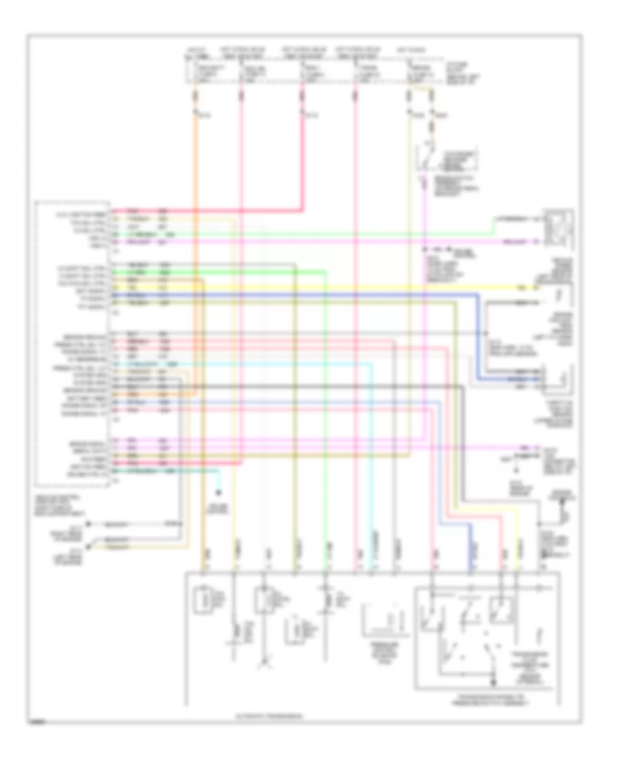
4.3L (VIN W), Transmission Wiring Diagram, with PCM for GMC Jimmy 1995
List of elements for 4.3L (VIN W), Transmission Wiring Diagram, with PCM for GMC Jimmy 1995:
- (behind left side of i/p)
- (left cylinder
- (upper intake manifold)
- 1-2 shift sol ctrl
- 1-2 shift sol.
- 2-3 shift sol ctrl
- 2-3 shift sol.
- 3-2 cntrl sol.
- 3-2 sol ctrl
- 5v reference
- A12
- A14
- A15
- All times
- Automatic transmission
- B10
- Battery feed
- Brake
- Brake signal
- Brake switch assembly (on brake pedal bracket)
- Cruise control
- Cruise ctrl in
- Data link connector (below left side of i/p)
- Diagnostic test
- E10
- E11
- E13
- E15
- E16
- Ecm batt
- Ecm ign fuse 10 20a
- Ect signal
- Eng 1
- Engine controls
- Engine coolant temp sensor
- F10
- F12
- F13
- F14
- F15
- Fuse 18 20a
- Fuse 23 10a
- Fuse 5 20a
- Fuse 9 20a
- G114 (left rear of engine)
- G115 (rear of engine)
- G117 (right rear of engine)
- Head)
- Hot at
- Hot in run
- Hot in run, bulb
- I/p fuse block
- Ignition feed
- Pnk
- Powertrain control module (pcm) (behind right side of i/p)
- Press ctrl sol "hi"
- Press ctrl sol "lo"
- Pressure control solenoid (pcs)
- Range signal "a"
- Range signal "b"
- Range signal "c"
- Red
- S106
- S110 (eng harn, 10 cm from spd sensor)
- S115 (eng harn, 5 cm from g115 breakout)
- S116
- S118
- S119
- S207
- S212 (dash harn, 10 cm from stoplamp sw breakout)
- S240
- Sensor ground
- Serial data
- System gnd
- Tan
- Tcc on/ off sol.
- Tcc pwm sol ctrl
- Tcc pwm sol.
- Tcc sol ctrl
- Tcc/cruise release brake switch
- Test or start
- Tft signal
- Throttle position sensor
- Tp signal
- Trans
- Transmission fluid temperature (tft) sensor (internal)
- Transmission range (tr) pressure switch assembly
- Vehicle speed sensor (left rear of transmission)
- Vehicle speed sensor buffer (behind right side of i/p)
- Vehicle speed signal
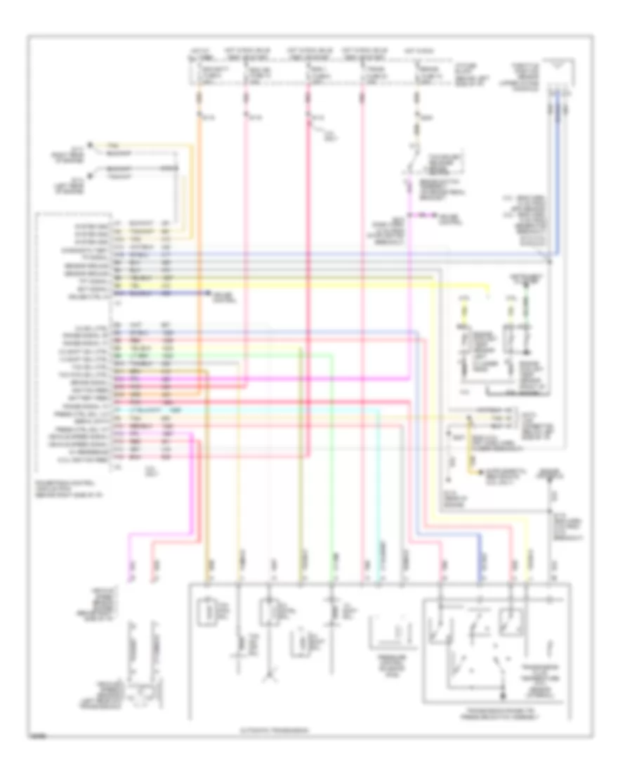
4.3L (VIN W), Transmission Wiring Diagram, with VCM for GMC Jimmy 1995
List of elements for 4.3L (VIN W), Transmission Wiring Diagram, with VCM for GMC Jimmy 1995:
- (4.3l) ignition feed
- (behind left side of i/p)
- (left cylinder
- (upper intake manifold)
- 1-2 shift sol ctrl
- 1-2 shift sol.
- 2-3 shift sol ctrl
- 2-3 shift sol.
- 3-2 cntrl sol.
- 3-2 sol ctrl
- 5v reference
- All times
- Automatic transmission
- Battery feed
- Brake
- Brake signal
- Brake switch assembly (on brake pedal bracket)
- Cruise control
- Cruise ctrl in
- Data link connector (below left side of i/p)
- Ecm batt
- Ecm ign fuse 10 20a
- Ect signal
- Eng 1
- Engine controls
- Engine coolant temp sensor
- Fuse 18 20a
- Fuse 23 10a
- Fuse 5 20a
- Fuse 9 20a
- G114 (left rear of engine)
- G115 (rear of engine)
- G117 (right rear of engine)
- Head)
- Hot at
- Hot in run
- Hot in run, bulb
- I/p fuse block
- Ignition feed
- Pnk
- Press ctrl sol "hi"
- Press ctrl sol "lo"
- Pressure control solenoid (pcs)
- Range signal "a"
- Range signal "b"
- Range signal "c"
- Red
- Run feed
- S106
- S110 (eng harn, 10 cm from spd sensor)
- S116
- S118
- S120
- S122 (eng harn, 5 cm from g115 breakout)
- S207
- S212 (dash harn, 10 cm from stoplamp sw breakout)
- S240
- Sensor ground
- Serial data
- System gnd
- Tcc on/ off sol.
- Tcc pwm sol ctrl
- Tcc pwm sol.
- Tcc sol ctrl
- Tcc/cruise release brake switch
- Test or start
- Tft signal
- Throttle position sensor
- Tp signal
- Trans
- Transmission fluid temperature (tft) sensor (internal)
- Transmission range (tr) pressure switch assembly
- Vehicle control module (vcm) (right side of eng compartment)
- Vehicle speed sensor (left rear of transmission)
- Vss hi
- Vss lo
4.3L (VIN Z), Transmission Wiring Diagram, with PCM for GMC Jimmy 1995
List of elements for 4.3L (VIN Z), Transmission Wiring Diagram, with PCM for GMC Jimmy 1995:
- (4.3l) ignition feed
- (behind left side of i/p)
- (front of
- (left
- (upper intake manifold)
- 1-2 shift sol ctrl
- 1-2 shift sol.
- 2-3 shift sol ctrl
- 2-3 shift sol.
- 2.2l
- 3-2 cntrl sol.
- 3-2 sol ctrl
- 4.3l
- 4.3l - (eng harn, 10 cm from spd sensor) 2.2l - (eng harn, 6 cm from generator breakout) s110 (4.3l) s107 (2.2l)
- 4.3l only
- 5v reference
- A12
- A14
- A15
- All times
- Automatic transmission
- B10
- Battery feed
- Brake
- Brake signal
- Brake switch assembly (on brake pedal bracket)
- Cruise control
- Cruise ctrl in
- Cylinder head)
- Data link connector (below left side of i/p)
- Diagnostic test
- E10
- E11
- E13
- E15
- E16
- Ecm batt
- Ecm ign fuse 10 20a
- Ect signal
- Eng 1
- Engine controls
- Engine coolant temp sensor
- Engine)
- F10
- F12
- F13
- F14
- F15
- Fuse 18 20a
- Fuse 23 10a
- Fuse 5 20a
- Fuse 9 20a
- G114 (left rear of engine)
- G115 (rear of engine)
- G117 (right rear of engine)
- Hot at
- Hot in run
- Hot in run, bulb
- I/p fuse block
- Ignition feed
- Instrument cluster
- Pnk
- Powertrain control module (pcm) (behind right side of i/p)
- Press ctrl sol "hi"
- Press ctrl sol "lo"
- Pressure control solenoid (pcs)
- Range signal "a"
- Range signal "b"
- Range signal "c"
- Red
- S106
- S115 (eng harn, 5 cm from g115 breakout)
- S116
- S118
- S119
- S207
- S212 (dash harn, 10 cm from stoplamp sw breakout)
- S240
- S248 (2.2l) (frt dash harn, in derm breakout)
- Sensor ground
- Serial data
- System gnd
- Tan
- Tcc on/ off sol.
- Tcc pwm sol ctrl
- Tcc pwm sol.
- Tcc sol ctrl
- Tcc/cruise release brake switch
- Test or start
- Tft signal
- Throttle position sensor
- Tp signal
- Trans
- Transmission fluid temperature (tft) sensor (internal)
- Transmission range (tr) pressure switch assembly
- Vehicle speed sensor (left rear of transmission)
- Vehicle speed sensor buffer (behind right side of i/p)
- Vehicle speed signal
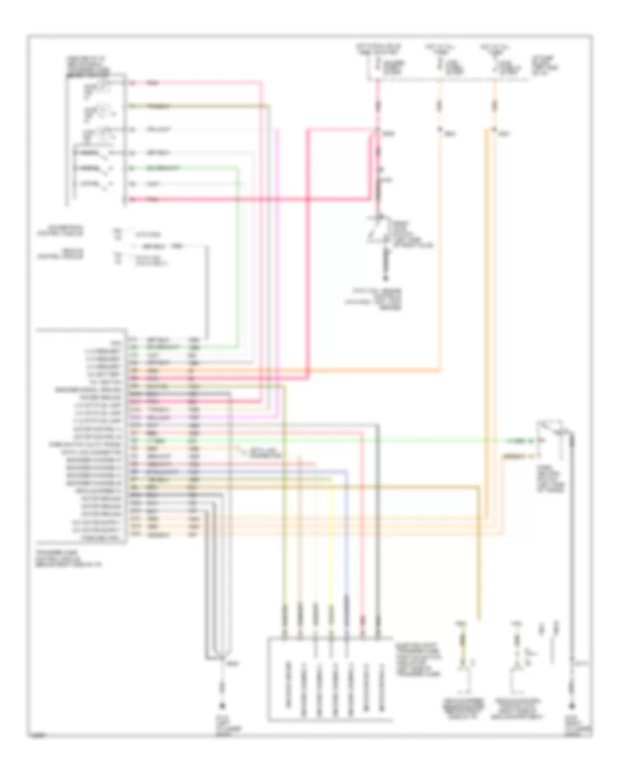
Transfer Case Wiring Diagram for GMC Jimmy 1995
List of elements for Transfer Case Wiring Diagram for GMC Jimmy 1995:
- (center of i/p, above radio) transfer case select switch
- 12v battery
- 12v ignition
- 2 hi request
- 2 hi status lamp
- 2wd ind hi
- 2wd-hi
- 4 hi request
- 4 hi status lamp
- 4 lo request
- 4 lo status lamp
- 4wd fuse 19 20 amp
- 4wd hi
- 4wd ind hi
- 4wd ind lo
- 4wd lo
- C10
- C11
- C12
- C14
- C154
- C16
- Ctsy fuse 3 20 amp
- D10
- D12
- D13
- D14
- D15
- D16
- Data link connector
- Electric shift transfer case position switch and motor (left side of transfer case)
- Encoder channel a
- Encoder channel b
- Encoder channel c
- Encoder channel p
- Encoder channel-a
- Encoder channel-b
- Encoder channel-c
- Encoder channel-p
- Encoder ground
- Encoder signal ground
- Front axle switch (left side of front axle)
- G112 (left cylinder head)
- G120 (right cylinder head)
- Gauges fuse 4 20 amp
- Hot at all times
- Hot in run, bulb test or start
- I/p fuse block (left end of i/p)
- Motor control a
- Motor control b
- Motor ground
- Park switch (auto trans)
- Park/ neutral switch (left side of trans)
- Park/neutral
- Pcm
- Pnk
- Power ground
- Powertrain control module
- Red
- S113
- S208
- S221
- S239
- S244
- Transfer case control module (behind right side of i/p)
- Vcm
- Vehicle control module
- Vehicle control module (vcm) (right side of eng compartment)
- Vehicle speed in
- Vehicle speed sensor buffer (behind right side of i/p)
- Vin w
- Vin z
- With pcm
- With vcm (vin w only)
- With vcm - engine controls with pcm - anti lock brakes
TRUNK, TAILGATE, FUEL DOOR
Rear Glass Release Wiring Diagram for GMC Jimmy 1995
List of elements for Rear Glass Release Wiring Diagram for GMC Jimmy 1995:
- A/t
- C 1995 vftc
- G114 (v6 vin z, w) (rear of left cylinder head)
- G117 (l4 vin 4) (right rear of engine)
- Horn/dm fuse 2 20a
- Hot at all times
- I/p fuse block
- Instrument cluster system
- Interior lights system
- M/t
- Park brake warning switch (at park brake)
- Park/ neutral position switch (left side of transmission)
- Rear window release solenoid
- Rear window release switch
- Red
- Remote keyless entry module
- Transfer case control module
WARNING SYSTEMS
Warning System Wiring Diagrams for GMC Jimmy 1995
List of elements for Warning System Wiring Diagrams for GMC Jimmy 1995:
- Audio alarm module (on convenience center)
- Fasten belts indicator
- Fasten belts output
- Fuse block
- G110 (lower left front of engine) (l4 vin 4)
- G117 (right rear of engine) (v6 vin w)
- Gauges fuse 4 20a
- Ground
- Hot at all times
- Hot in run, bulb test or start
- Hot with headlight switch in park or head
- Ignition on input
- Illum fuse 14 10a
- Instrument cluster
- Key-in warning
- Key-in warning buzzer switch
- Left door jamb switch
- Lights on input
- Nca
- Pnk
- Power input
- Safety belt input
- Safety belt retractor switch
- Stop-hz fuse 1 20a
- Tan
WIPER/WASHER
Front Washer/Wiper Wiring Diagram for GMC Jimmy 1995
List of elements for Front Washer/Wiper Wiring Diagram for GMC Jimmy 1995:
- (on left radiator support)
- C 1995 vftc
- Control area
- Delay/ speed/ wash control
- Fusible link
- G108
- G117 (rear of right cylinder head)
- Hot in accy or run
- I/p fuse block
- Ign
- Low
- Mist
- Off
- Park switch
- Pnk
- Pulse
- Wash pulse switch
- Windshield washer pump (above left wheel well)
- Windshield wiper motor module (left side of engine compt)
- Windshield wiper/ washer switch
- Wiper fuse 17 25a
Rear Wiper/Washer Wiring Diagram for GMC Jimmy 1995
List of elements for Rear Wiper/Washer Wiring Diagram for GMC Jimmy 1995:
- C 1995 vftc
- G108 (on left radiator support)
- G117 (rear of right cylinder head)
- Headlight switch
- Hot at all times
- Hot in accy or run
- Hot with headlight switch in park or head
- I/p fuse block
- Illum fuse 14 10a
- Illum light
- Off
- Radio fuse 11 20a
- Rear endgate door jamb switch (center of liftgate)
- Rear window washer pump (above left wheel well)
- Rear window wiper motor and module (center of liftgate)
- Rear wiper/ washer switch
- T/l ctsy fuse 3 20a
- Wash

 Čeština
 Dansk
Dansk Deutsch
 Ελληνικά
 English
 English
 Español
 Suomi
Suomi Français
 עברית
עברית Hrvatski
 Magyar
 Italiano
 日本語
日本語 한국어
한국어 Nederlands
 Polski
 Português
 Português
 Română
 Русский
 Slovenčina
 Slovenščina
 Svenska
 Türkçe
 中文 (中国)