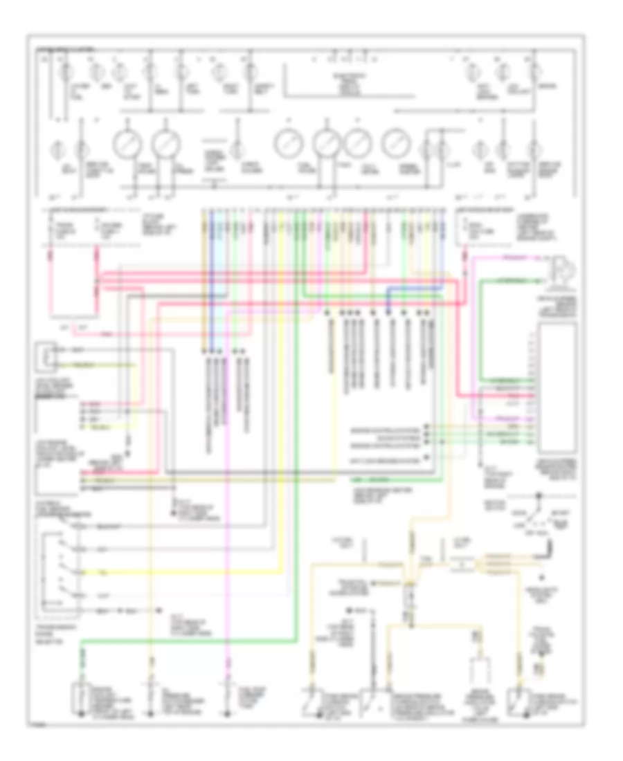
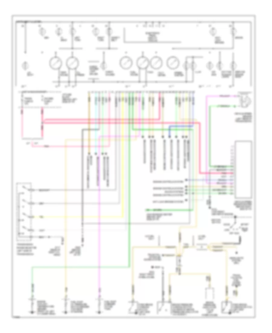
AIR CONDITIONING
A/C Wiring Diagram for GMC Pickup K1995 2500
 https://portal-diagnostov.com/license.html
Automotive Electricians Portal FZCO
Automotive Electricians Portal FZCO
https://portal-diagnostov.com/license.html
https://portal-diagnostov.com/license.html
Automotive Electricians Portal FZCO
Automotive Electricians Portal FZCO
List of elements for A/C Wiring Diagram for GMC Pickup K1995 2500:
- (rear of compressor)
- (rear of right cylinder head)
- A/c compressor clutch
- A/c compressor clutch relay (under i/p, on top of heater-a/c case)
- A/c fuse 10a
- A/c fuse 50a
- A/c high pressure cutout switch (at a/c compressor)
- A/c low pressure cutout switch (at a/c accumulator)
- A/c signal
- Above starter motor)
- Aux fan mini fuse 30a
- Auxiliary
- Auxiliary cooling fan a/c pressure switch
- Auxiliary cooling fan relay (in underhood fuse/relay center)
- Auxiliary cooling fan temperature switch (right cylinder head
- Blower motor
- Blower resistor (under right side of i/p, on heater housing)
- C10
- Comp clutch ctrl
- Cooling fan motor
- Diesel
- Diode
- E12
- Fan control
- Fuse block
- G101 (right inner fender, near battery)
- G108 (on left radiator support)
- G120
- G120 (rear of right cylinder head)
- G202 (below i/p, near data link connector)
- Gas a/t
- Gas m/t
- Ground
- Heater and a/c control module
- High blower relay
- High blower relay (under i/p on top of heater-a/c case)
- Hot at all times
- Hot in run
- Hot in run bulb test or start
- Htr a/c fuse 25a
- Ign e mini fuse 10a
- Ignition
- Illumination
- Interior lights system
- Lo blower
- Med 1 blower
- Med 2 blower
- Mode door actuator (under i/p on heater- a/c case)
- Mode door input
- Nca
- Pnk
- Powertrain control module (under right side of i/p)
- Recirc door input
- Red
- Tan
- Temp door input
- Temperature door actuator (under i/p on heater- a/c case)
- Underhood fuse-relay center
- Water valve (suburban only) (right center of intake area)
- Water valve ctrl
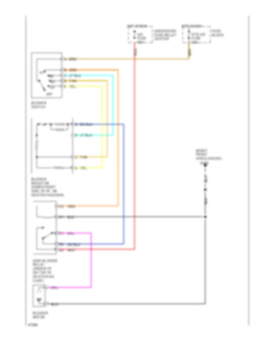
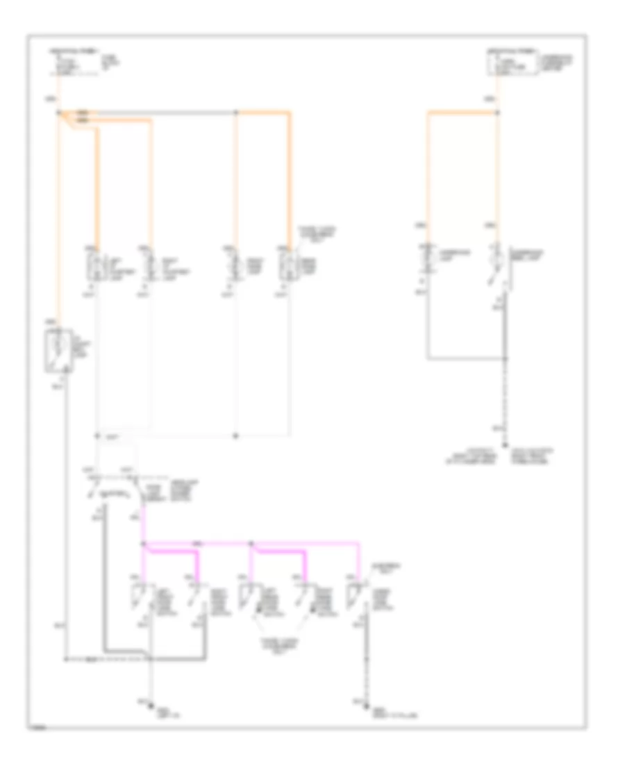
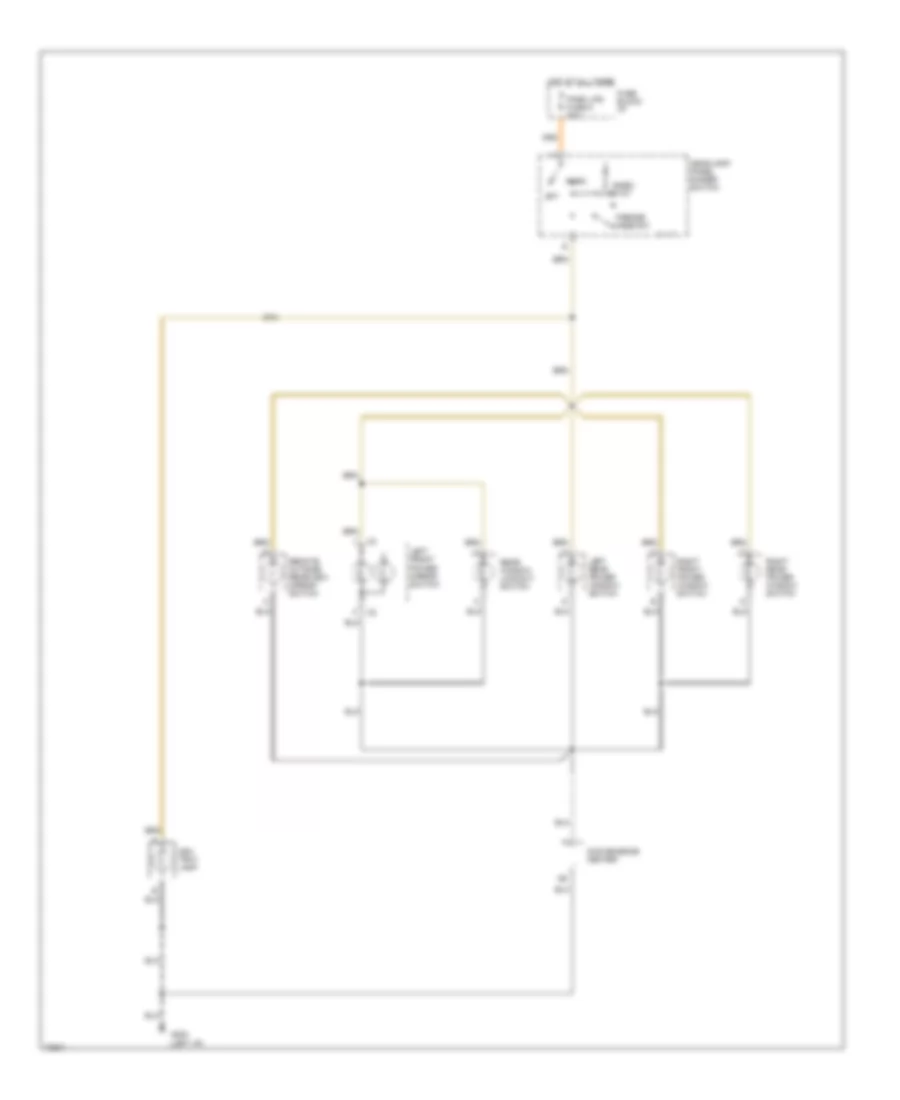
Heater Wiring Diagram for GMC Pickup K1995 2500
List of elements for Heater Wiring Diagram for GMC Pickup K1995 2500:
- (right front wheelhouse)
- A/c fuse 50a
- Blower motor
- Blower resistor (under right side of i/p, on heater housing)
- Blower switch
- Fuse block
- G100
- High blower relay (under i/p on top of heater-a/c case)
- Hot in run
- Htr a/c fuse 25a
- Off
- Red
- Tan
- Underhood fuse-relay center
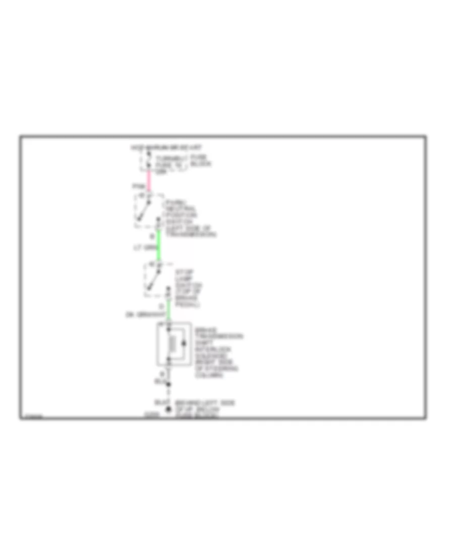
ANTI-LOCK BRAKES
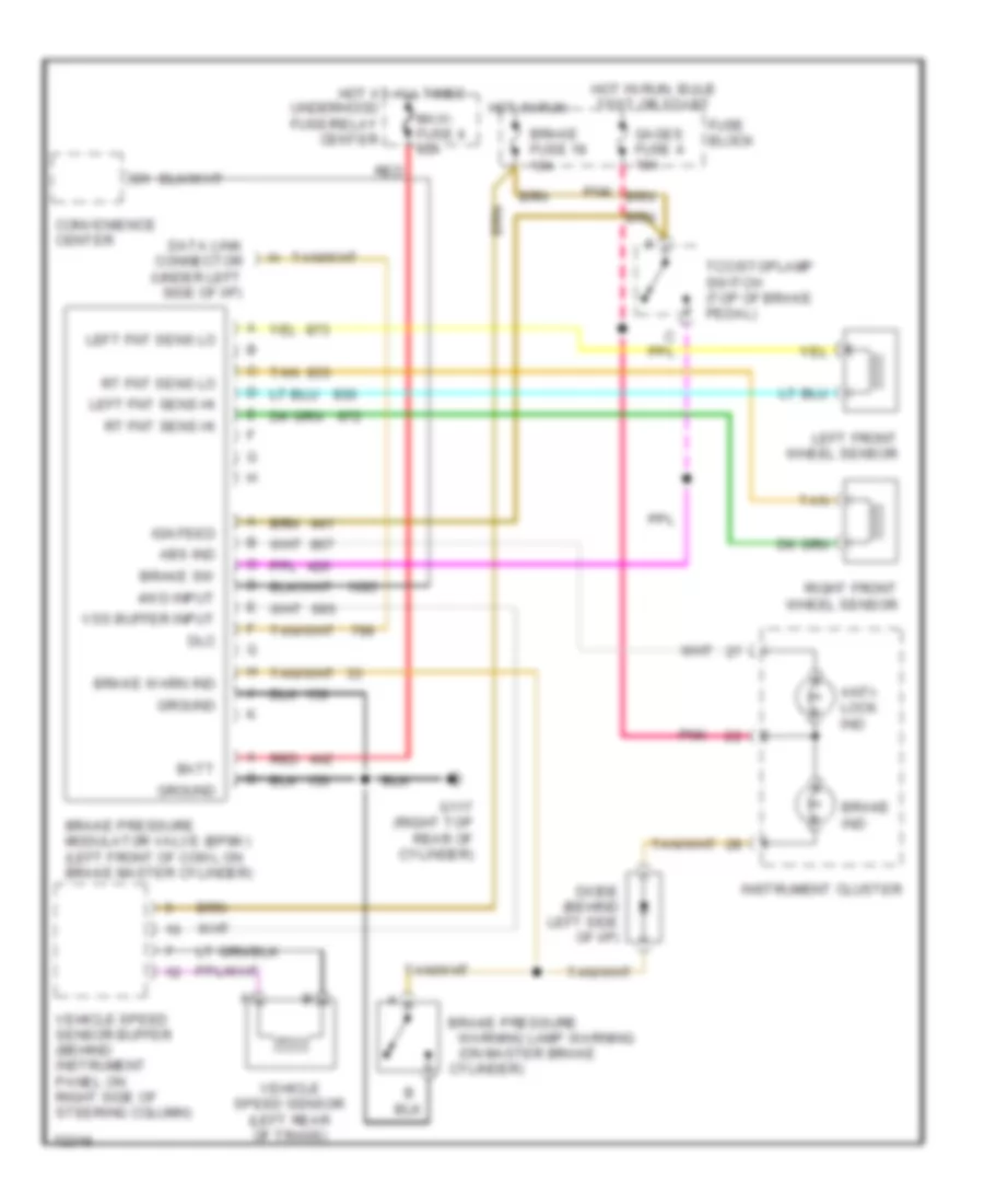
Anti-lock Brake Wiring Diagrams for GMC Pickup K1995 2500
List of elements for Anti-lock Brake Wiring Diagrams for GMC Pickup K1995 2500:
- (on master brake
- 4wd input
- Abs ind
- Anti- lock ind
- Batt
- Brake fuse 18 10a
- Brake ind
- Brake pressure
- Brake pressure modulator valve (bpmv) (left front of cowl on brake master cylinder)
- Brake sw
- Brake warn ind
- Convenience center
- Cylinder)
- Data link connector (under left side of i/p)
- Diode (behind left side of i/p)
- Dlc
- Fuse block
- G117 (right top rear of cylinder)
- Gages fuse 4 10a
- Ground
- Hot at all times
- Hot in run
- Hot in run, bulb test or start
- Ign feed
- Instrument cluster
- Left fnt sens hi
- Left fnt sens lo
- Left front wheel sensor
- Maxi- fuse 4 60a
- Pnk
- Red
- Right front wheel sensor
- Rt fnt sens hi
- Rt fnt sens lo
- Tan
- Tcc/stoplamp switch (top of brake pedal)
- Underhood fuse/relay center
- Vehicle speed sensor (left rear of trans)
- Vehicle speed sensor buffer (behind instrument panel on right side of steering column)
- Vss buffer input
- Warning lamp warning
COMPUTER DATA LINES
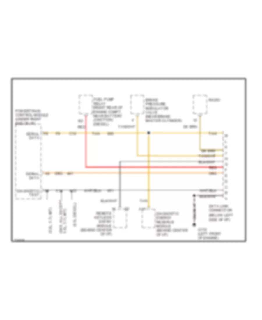
Data Link Connector Wiring Diagram for GMC Pickup K1995 2500
List of elements for Data Link Connector Wiring Diagram for GMC Pickup K1995 2500:
- (5.0l, 5.7l m/t)
- (6.5l diesel)
- (below left side of i/p)
- (gas, all except 5.0l, 5.7l m/t)
- A11
- A12
- A14
- Brake pressure modulator valve (near brake master clyinder)
- C14
- Data link connector
- Diagnostic energy reserve module (behind center of i/p)
- Diagnostic test
- F9 serial data
- Fuel pump relay (right rear of engine compt, near battery junction) (diesel)
- G110 (left front of engine)
- Powertrain control module (under right end of i/p)
- Radio
- Red
- Remote keyless entry module (behind center of i/p)
- Serial data
- Tan
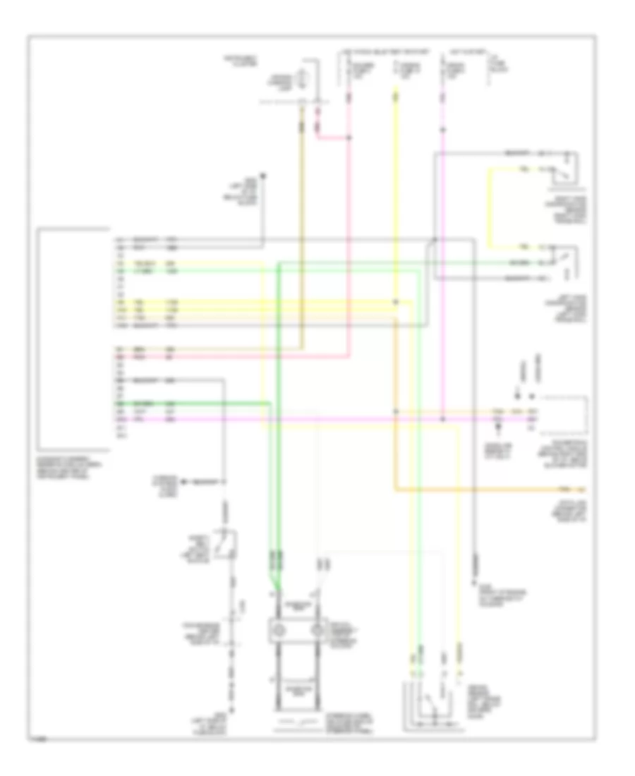
COOLING FAN
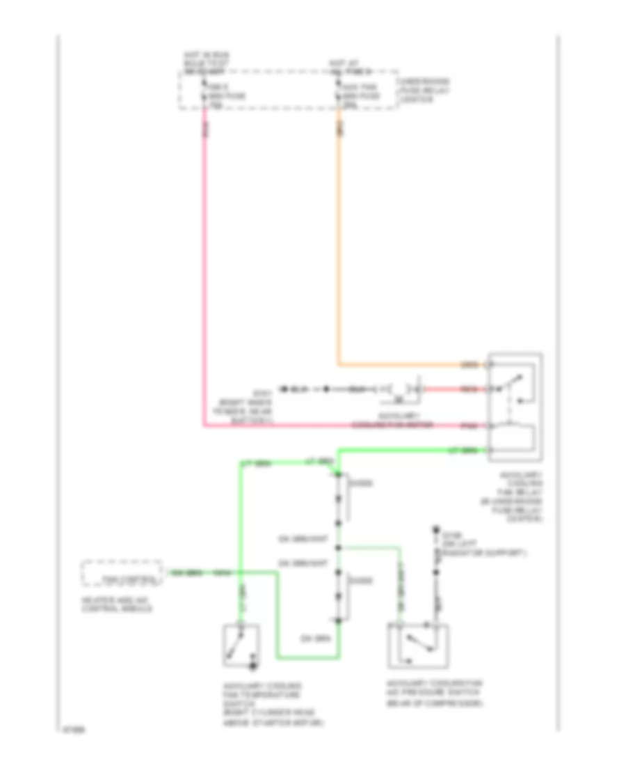
Cooling Fan Wiring Diagram for GMC Pickup K1995 2500
List of elements for Cooling Fan Wiring Diagram for GMC Pickup K1995 2500:
- (rear of compressor)
- Above starter motor)
- Aux fan mini fuse 30a
- Auxiliary
- Auxiliary cooling fan a/c pressure switch
- Auxiliary cooling fan relay (in underhood fuse/relay center)
- Auxiliary cooling fan temperature switch (right cylinder head
- Cooling fan motor
- Diode
- Fan control
- G101 (right inner fender, near battery)
- G108 (on left radiator support)
- Heater and a/c control module
- Hot at all times
- Hot in run bulb test or start
- Ign e mini fuse 10a
- Pnk
- Red
- Underhood fuse-relay center
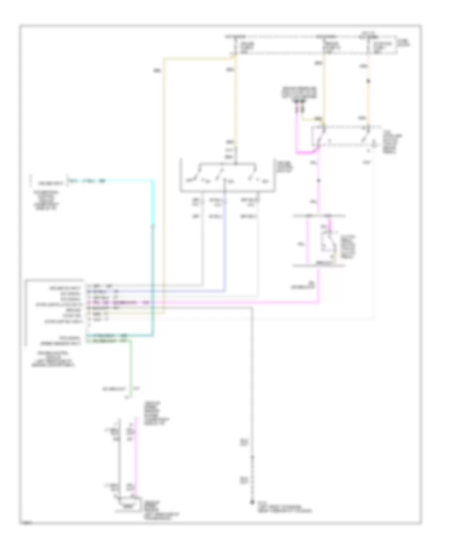
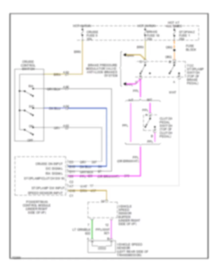
CRUISE CONTROL
4.3L
4.3L (VIN Z), Cruise Control Wiring Diagram for GMC Pickup K1995 2500
List of elements for 4.3L (VIN Z), Cruise Control Wiring Diagram for GMC Pickup K1995 2500:
- 12vdc ign
- A/t
- A12
- A13
- A14
- A15
- B10
- Brake fuse 18 10a
- Brake pressure modulator valve: anti-lock brakes system
- Clutch pedal switch (top of clutch pedal)
- Cruise control module (left rear side of engine compartment)
- Cruise control switch
- Cruise fuse 6 10a
- Cruise input
- Cruise on input
- Fuse block
- G110 (left front of engine, near thermostat housing)
- Ground
- Hot at all times
- Hot in run
- M/t
- Off
- Pcm signal
- Powertrain control module (under right side of i/p)
- R/a
- R/a signal
- S/c
- S/c signal
- Speed sensor input
- Stop/haz fuse 1 20a
- Stoplamp sw input
- Stoplamp/clutch sw in
- Tcc stoplamp switch (top of brake pedal)
- Vehicle speed sensor (left rear side of transmission)
- Vehicle speed sensor buffer (under right side of i/p)
5.0L
5.0L (VIN H), Cruise Control Wiring Diagram for GMC Pickup K1995 2500
List of elements for 5.0L (VIN H), Cruise Control Wiring Diagram for GMC Pickup K1995 2500:
- 12vdc ign
- A/t
- A12
- A13
- A14
- A15
- B10
- Brake fuse 18 10a
- Brake pressure modulator valve: anti-lock brakes system
- Clutch pedal switch (top of clutch pedal)
- Cruise control module (left rear side of engine compartment)
- Cruise control switch
- Cruise fuse 6 10a
- Cruise input
- Cruise on input
- Fuse block
- G110 (left front of engine, near thermostat housing)
- Ground
- Hot at all times
- Hot in run
- M/t
- Off
- Pcm signal
- Powertrain control module (under right side of i/p)
- R/a
- R/a signal
- S/c
- S/c signal
- Speed sensor input
- Stop/haz fuse 1 20a
- Stoplamp sw input
- Stoplamp/clutch sw in
- Tcc stoplamp switch (top of brake pedal)
- Vehicle speed sensor (left rear side of transmission)
- Vehicle speed sensor buffer (under right side of i/p)
5.7L
5.7L (VIN K), Cruise Control Wiring Diagram for GMC Pickup K1995 2500
List of elements for 5.7L (VIN K), Cruise Control Wiring Diagram for GMC Pickup K1995 2500:
- 12vdc ign
- A/t
- A12
- A13
- A14
- A15
- B10
- Brake fuse 18 10a
- Brake pressure modulator valve: anti-lock brakes system
- Clutch pedal switch (top of clutch pedal)
- Cruise control module (left rear side of engine compartment)
- Cruise control switch
- Cruise fuse 6 10a
- Cruise input
- Cruise on input
- Fuse block
- G110 (left front of engine, near thermostat housing)
- Ground
- Hot at all times
- Hot in run
- M/t
- Off
- Pcm signal
- Powertrain control module (under right side of i/p)
- R/a
- R/a signal
- S/c
- S/c signal
- Speed sensor input
- Stop/haz fuse 1 20a
- Stoplamp sw input
- Stoplamp/clutch sw in
- Tcc stoplamp switch (top of brake pedal)
- Vehicle speed sensor (left rear side of transmission)
- Vehicle speed sensor buffer (under right side of i/p)
6.5L
6.5L (VIN F), Cruise Control Wiring Diagram for GMC Pickup K1995 2500
List of elements for 6.5L (VIN F), Cruise Control Wiring Diagram for GMC Pickup K1995 2500:
- A/t
- A12
- A13
- A14
- A15
- Brake fuse 18 10a
- Brake pressure modulator valve: anti-lock brakes system
- C15
- Clutch pedal switch (top of clutch pedal)
- Cruise control switch
- Cruise fuse 6 10a
- Cruise on input
- D11
- D15
- Fuse block
- Hot at all times
- Hot in run
- M/t
- Off
- Powertrain control module (under right side of i/p)
- R/a
- R/a signal
- S/c
- S/c signal
- Speed sensor input
- Stop/haz fuse 1 20a
- Stoplamp sw input
- Stoplamp/clutch sw in
- Tcc stoplamp switch (top of brake pedal)
- Vehicle speed sensor (left rear side of transmission)
- Vehicle speed sensor buffer (under right side of i/p)
6.5L (VIN P), Cruise Control Wiring Diagram for GMC Pickup K1995 2500
List of elements for 6.5L (VIN P), Cruise Control Wiring Diagram for GMC Pickup K1995 2500:
- A/t
- A12
- A13
- A14
- A15
- Brake fuse 18 10a
- Brake pressure modulator valve: anti-lock brakes system
- C15
- Clutch pedal switch (top of clutch pedal)
- Cruise control switch
- Cruise fuse 6 10a
- Cruise on input
- D11
- D15
- Fuse block
- Hot at all times
- Hot in run
- M/t
- Off
- Powertrain control module (under right side of i/p)
- R/a
- R/a signal
- S/c
- S/c signal
- Speed sensor input
- Stop/haz fuse 1 20a
- Stoplamp sw input
- Stoplamp/clutch sw in
- Tcc stoplamp switch (top of brake pedal)
- Vehicle speed sensor (left rear side of transmission)
- Vehicle speed sensor buffer (under right side of i/p)
6.5L (VIN S), Cruise Control Wiring Diagram for GMC Pickup K1995 2500
List of elements for 6.5L (VIN S), Cruise Control Wiring Diagram for GMC Pickup K1995 2500:
- A/t
- A12
- A13
- A14
- A15
- Brake fuse 18 10a
- Brake pressure modulator valve: anti-lock brakes system
- C15
- Clutch pedal switch (top of clutch pedal)
- Cruise control switch
- Cruise fuse 6 10a
- Cruise on input
- D11
- D15
- Fuse block
- Hot at all times
- Hot in run
- M/t
- Off
- Powertrain control module (under right side of i/p)
- R/a
- R/a signal
- S/c
- S/c signal
- Speed sensor input
- Stop/haz fuse 1 20a
- Stoplamp sw input
- Stoplamp/clutch sw in
- Tcc stoplamp switch (top of brake pedal)
- Vehicle speed sensor (left rear side of transmission)
- Vehicle speed sensor buffer (under right side of i/p)
7.4L
7.4L (VIN N), Cruise Control Wiring Diagram for GMC Pickup K1995 2500
List of elements for 7.4L (VIN N), Cruise Control Wiring Diagram for GMC Pickup K1995 2500:
- 12vdc ign
- A/t
- A12
- A13
- A14
- A15
- B10
- Brake fuse 18 10a
- Brake pressure modulator valve: anti-lock brakes system
- Clutch pedal switch (top of clutch pedal)
- Cruise control module (left rear side of engine compartment)
- Cruise control switch
- Cruise fuse 6 10a
- Cruise input
- Cruise on input
- Fuse block
- G110 (left front of engine, near thermostat housing)
- Ground
- Hot at all times
- Hot in run
- M/t
- Off
- Pcm signal
- Powertrain control module (under right side of i/p)
- R/a
- R/a signal
- S/c
- S/c signal
- Speed sensor input
- Stop/haz fuse 1 20a
- Stoplamp sw input
- Stoplamp/clutch sw in
- Tcc stoplamp switch (top of brake pedal)
- Vehicle speed sensor (left rear side of transmission)
- Vehicle speed sensor buffer (under right side of i/p)
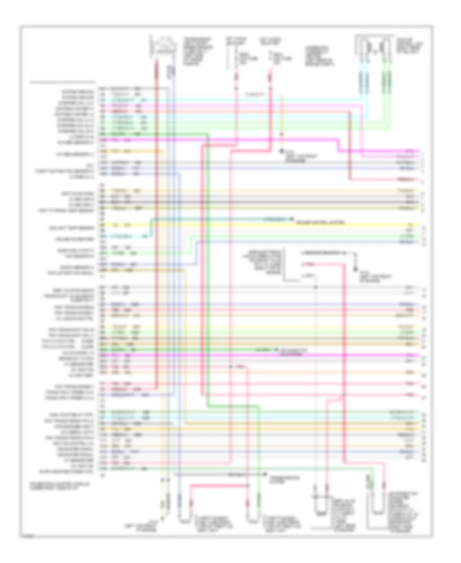
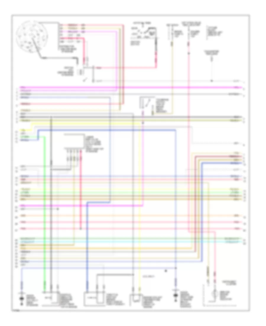
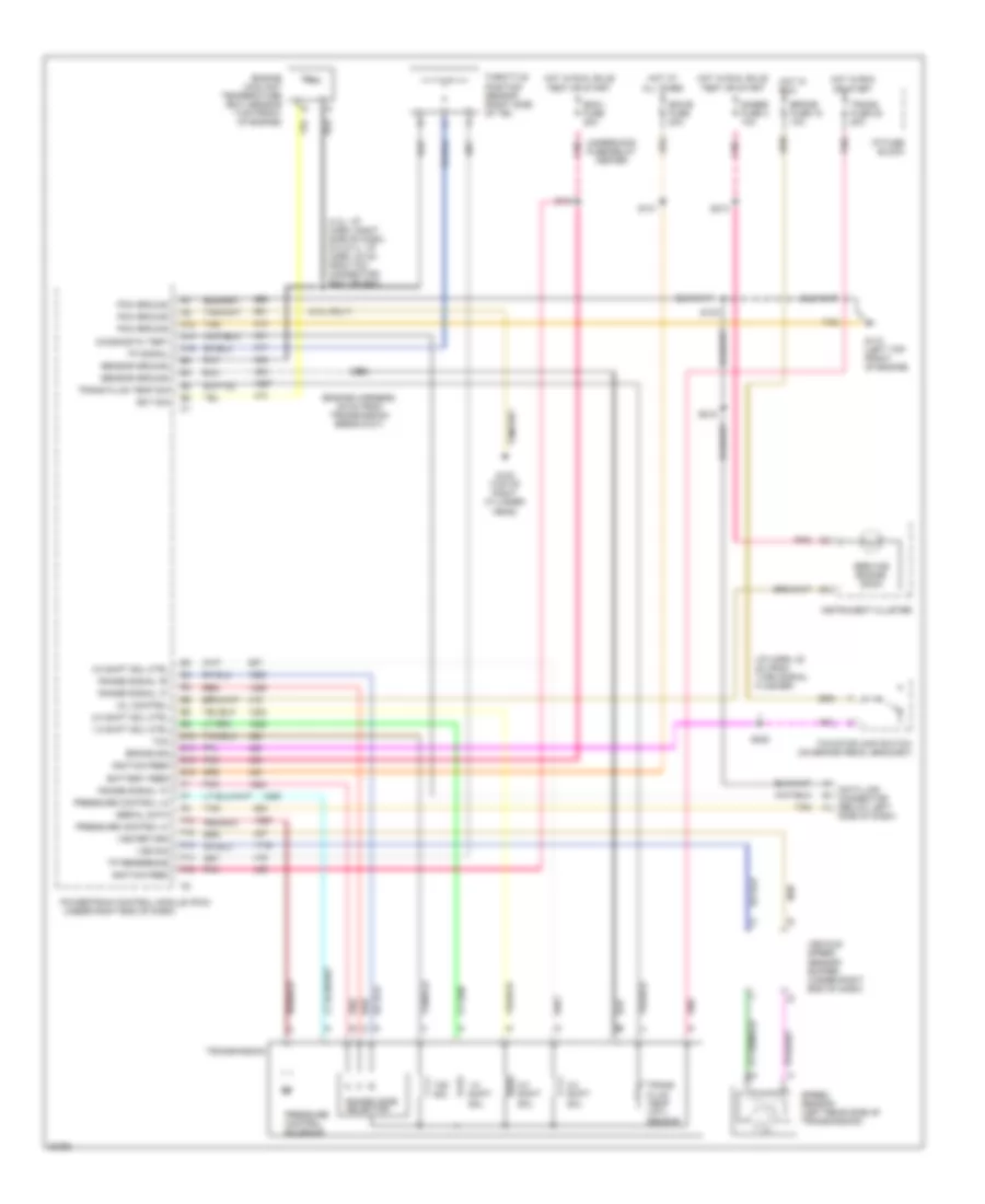
ENGINE PERFORMANCE
4.3L
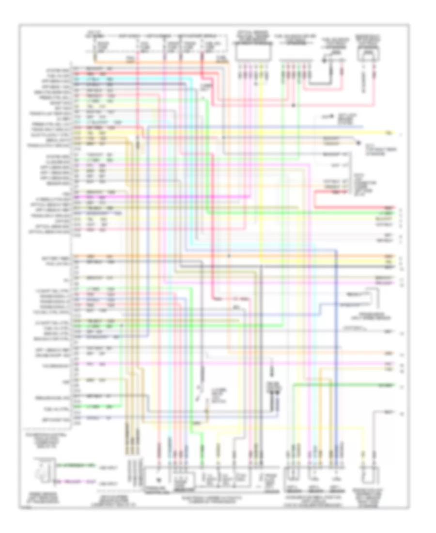
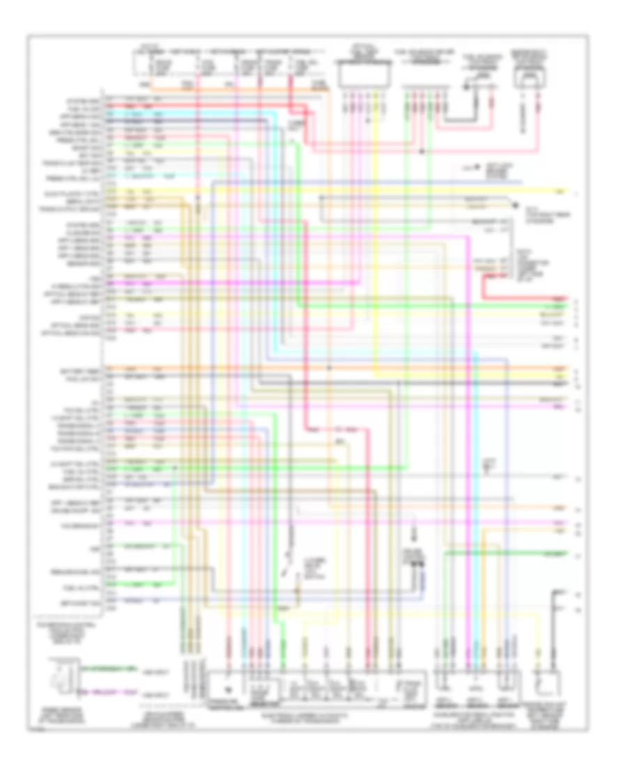
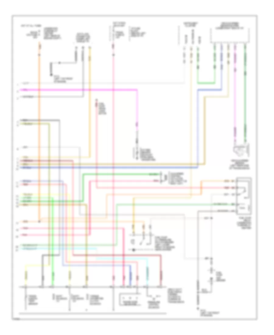
4.3L (VIN Z), Engine Performance Wiring Diagrams, A/T (1 of 3) for GMC Pickup K1995 2500
List of elements for 4.3L (VIN Z), Engine Performance Wiring Diagrams, A/T (1 of 3) for GMC Pickup K1995 2500:
- (4l60e)
- (4l80e)
- (left top front
- 12v battery
- 12v ignition
- 4wd engaged input
- 5v return a
- 5v return b
- 5v sensor ref
- A/c on signal in
- A10
- A11
- A12
- A13
- A14
- A15
- A16
- Air condition- ing system
- B10
- B11
- B12
- B13
- B14
- B15
- B16
- Brake sw to pcm
- Coolant temp sensor
- Cruise control system
- Cruise ind reg grd
- Distributor ref hi
- Distributor ref lo
- Dlc
- Dlc serial data
- E10
- E11
- E12
- E13
- E14
- E15
- E16
- Ecm-i mini fuse 20a
- Egr electronic vacuum regulator solenoid valve (5.7l w/ 4l80e) (right top of engine)
- Egr valve solenoid
- Egr valve solenoid (4.3/5.0/5.7l w/ 4l60e & 4.3l w/ 4l80e) (left rear of engine)
- Elec fuel pump in
- Eng-i mini fuse 20a
- Evap canister purge ctrl
- Evaporative canister purge solenoid (5.0 & 5.7l w/ 4l60e & 4.3l w/ 4l60e & calif emissions) (right side of engine)
- F10
- F11
- F12
- F13
- F14
- F15
- F16
- Fuel pump relay ctrl
- G110
- G110 (left top front of engine)
- Hot in run or start
- Idle air control unit (right rear of tbi unit)
- Ignition bypass
- Ignition control (ic)
- Knock sensor in
- Lo side inj a
- Lo side inj b
- Map sensor in
- Mil indicator ctrl
- Of engine)
- Oxygen sensor hi
- Oxygen sensor lo
- Pcm to trans temp sensor
- Pcm trans force mtr hi
- Pcm trans force mtr lo
- Pcm trans range a
- Pcm trans range b
- Pcm trans range c
- Pcm trans shift sol a
- Pcm trans shift sol b
- Pintle position signal
- Pnk
- Powertrain control module (under right side of i/p)
- Red
- Stepper coil a hi
- Stepper coil a lo
- Stepper coil b hi
- Stepper coil b lo
- System ground
- Tan
- Tcc clutch ctrl
- Throttle body fuel injector #1 (top of throttle body unit)
- Throttle body fuel injector #2 (top of throttle body unit)
- Throttle position sensor in
- Trans input speed in hi
- Trans input speed in lo
- Trans shift 3/2 solenoid (4l60e only)
- Transmission input shaft speed sensor (4l80e only) (left side of trans- mission)
- Transmissions system
- Underhood fuse/relay center (left rear of engine comp't)
- Vss buffer signal
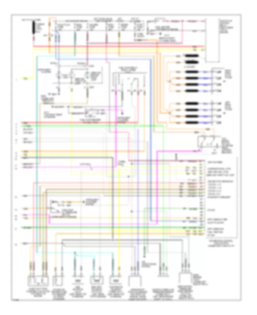
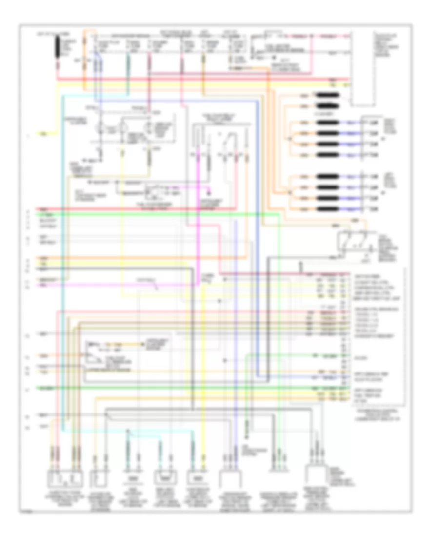
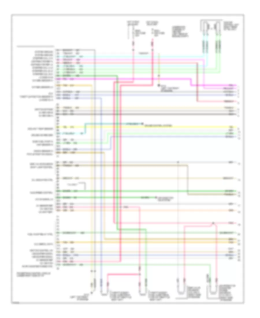
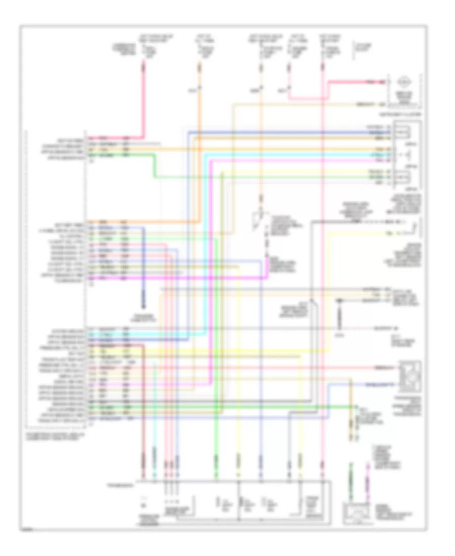
4.3L (VIN Z), Engine Performance Wiring Diagrams, A/T (2 of 3) for GMC Pickup K1995 2500
List of elements for 4.3L (VIN Z), Engine Performance Wiring Diagrams, A/T (2 of 3) for GMC Pickup K1995 2500:
- (4.3l only)
- (center rear
- Accy
- Brake fuse 18 10a
- Bulb test
- Distributor
- Engine coolant temperature sensor (front of engine)
- Gauges fuse 4 10a
- Hot at all times
- Hot in run
- Hot in run, bulb test, or start
- I/p fuse block (behind left side of i/p)
- Ignition coil (center rear of engine)
- Ignition switch
- Instrument cluster
- Knock sensor (4.3l only) (rear of engine)
- Knock sensor (right side of engine, below exhaust manifold)
- Linear egr valve (4.3l w/ 4l60e & calif emiss. only) (right side top of engine)
- Lock
- Manifold absolute pressure sensor (right rear top of engine)
- Nca
- Of engine)
- Off
- Pnk
- Red
- Run
- Service engine soon indicator
- Start
- Tachometer test lead
- Tan
- Tcc/brake switch (top of brake pedal bracket)
- Throttle position sensor (right side of throttle body)
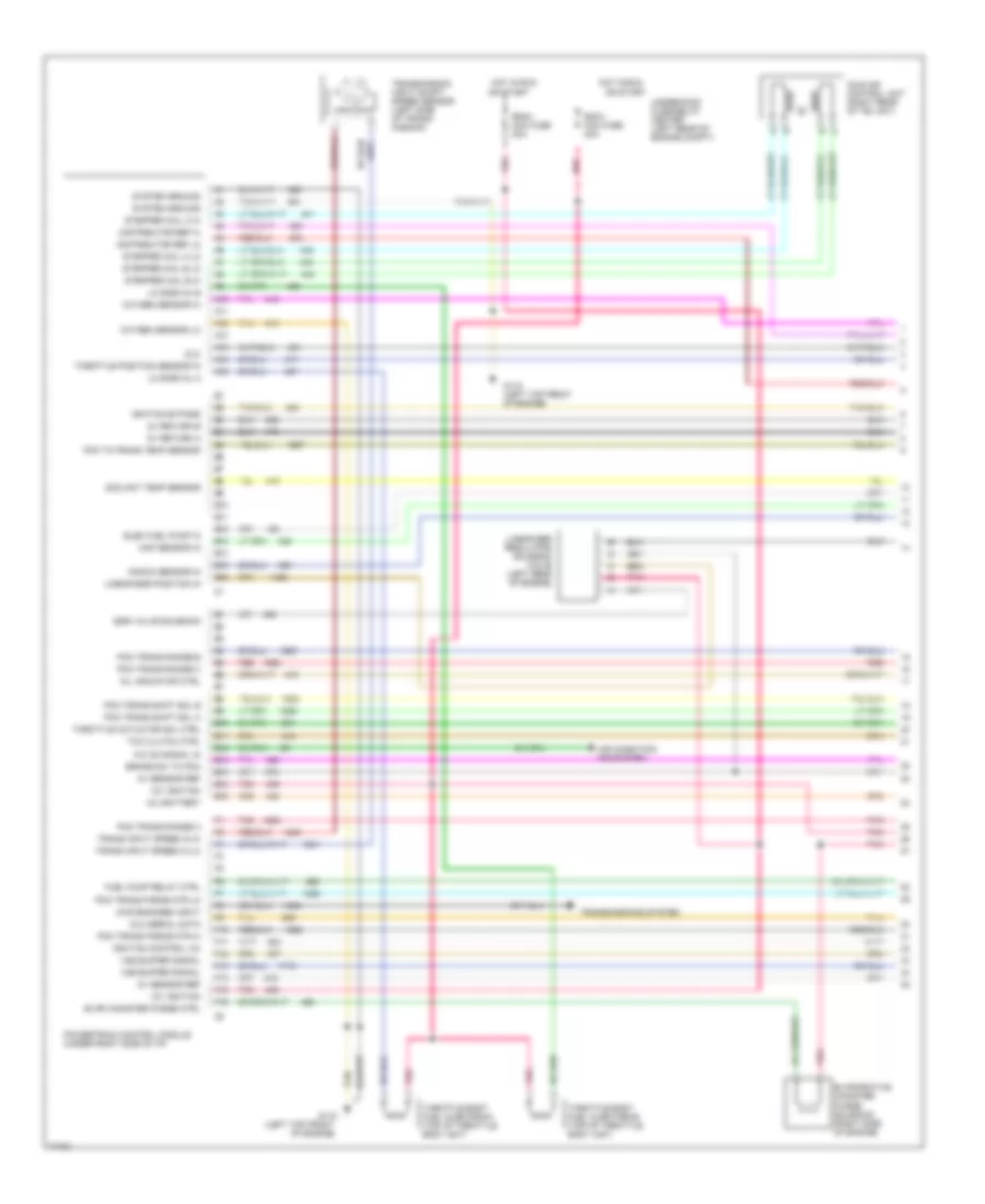
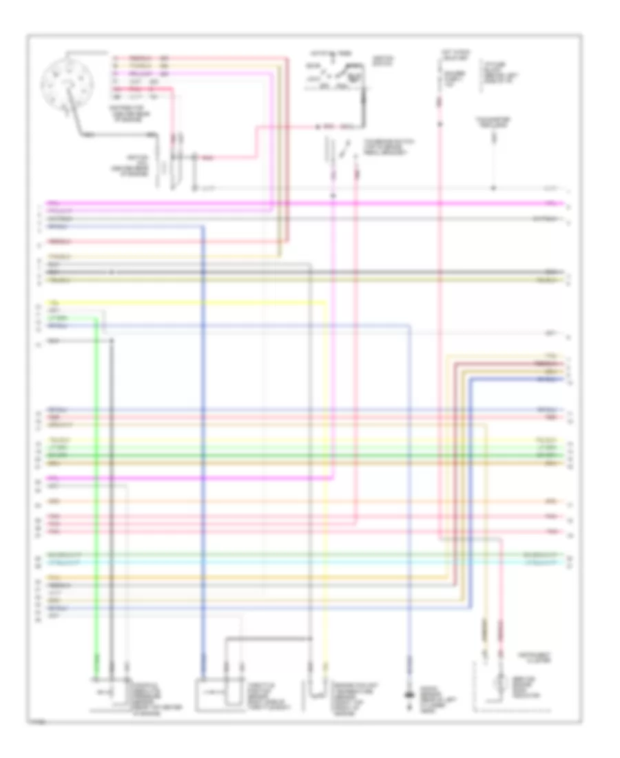
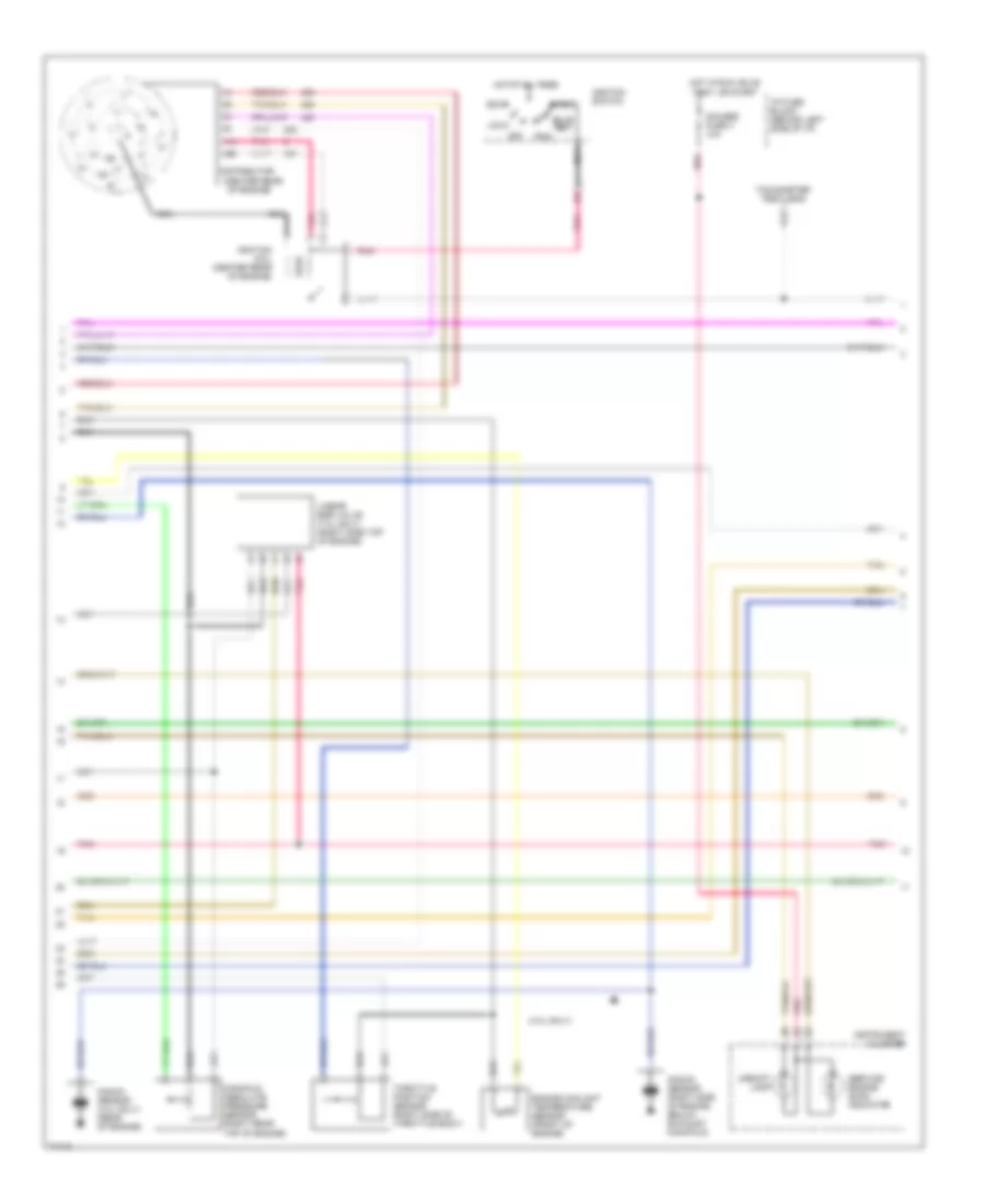
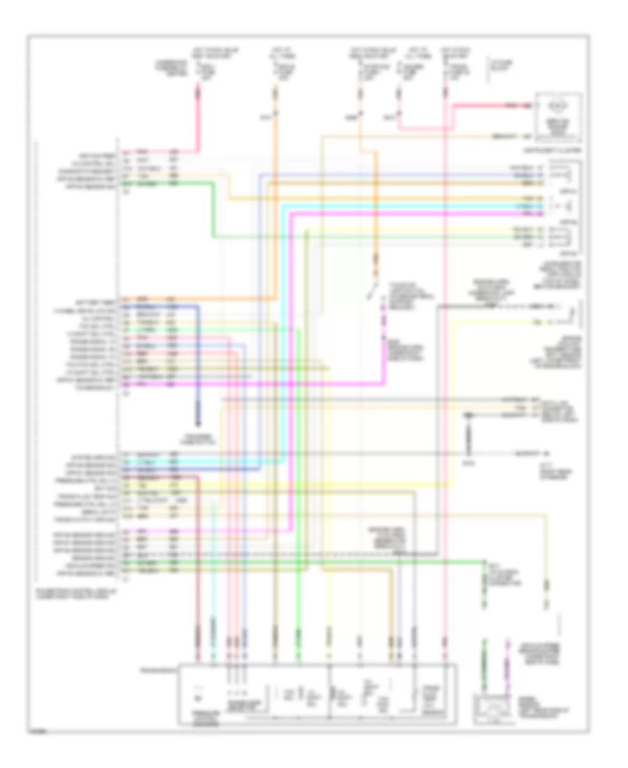
4.3L (VIN Z), Engine Performance Wiring Diagrams, A/T (3 of 3) for GMC Pickup K1995 2500
List of elements for 4.3L (VIN Z), Engine Performance Wiring Diagrams, A/T (3 of 3) for GMC Pickup K1995 2500:
- (4l60e
- (4l60e) t
- (4l80e) s
- 3-2 shift solenoid (4l60e only)
- All except 5.7l w/ 4l80e trans
- C11
- C12
- C13
- C15
- Cluster
- Data link connector (under left side of i/p)
- Ecm-b mini fuse 20a
- Electronic 4-speed automatic overdrive transmission
- Fuel pump and sender
- Fuel pump oil pressure switch (top rear of engine, near distributor)
- Fuel pump prime conn- ector
- Fuel pump relay (underhood fuse/relay center)
- G103 (right front wheelhouse)
- G110 (left top front of engine)
- Heated oxygen sensor (in exhaust y-pipe)
- Hot at all times
- Hot in run or start
- I/p fuse block (behind left side of i/p)
- Instrument
- Oil press in
- Only)
- Pnk
- Pressure control solenoid
- Range mode selector
- Red
- Shift sole- noid 1-2
- Shift solenoid 2-3
- Tach in
- Tan
- Torque converter clutch solenoid
- Trans fuse 20 10a
- Trans- mission temp sensor
- Underhood fuse/relay center (left rear of engine comp't)
- Vehicle speed sensor (left rear side of transmission)
- Vehicle speed sensor buffer (under right end of i/p)
- Vss in
- W/ 4l60e
- W/ 4l80e
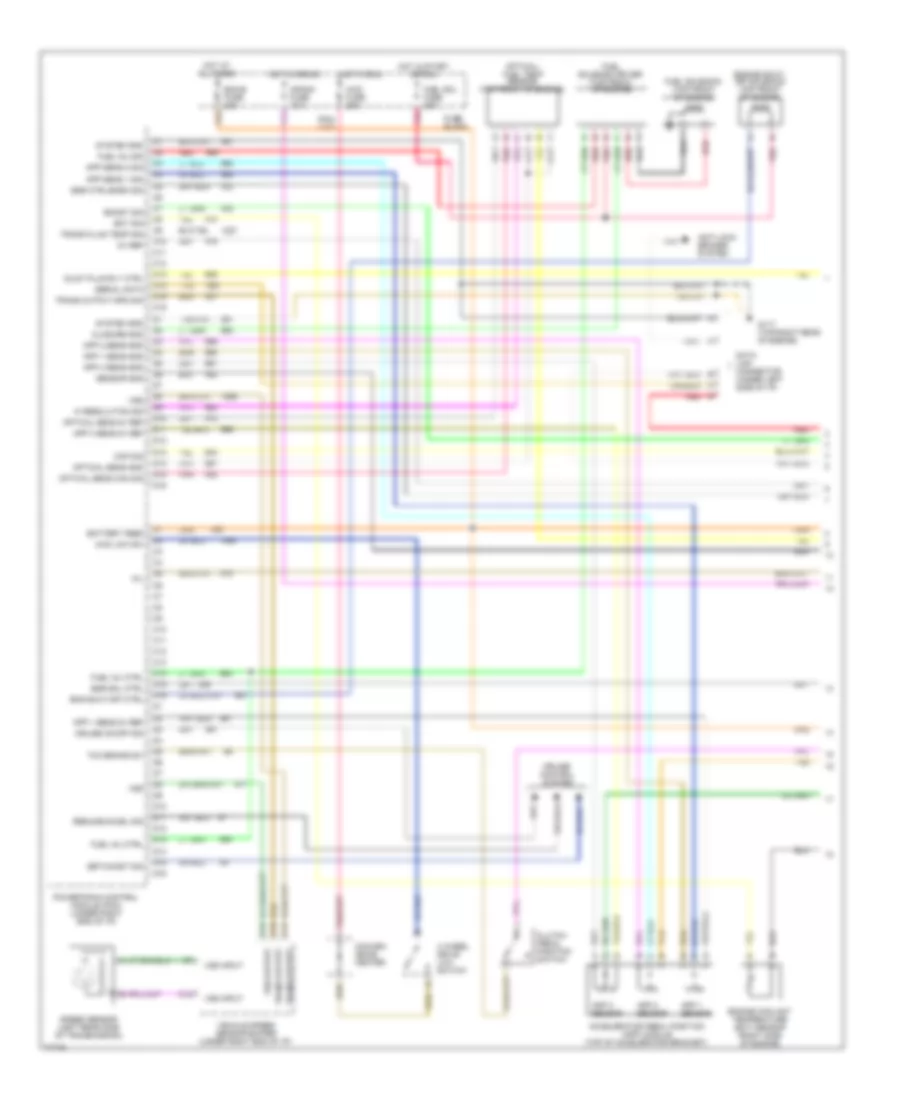
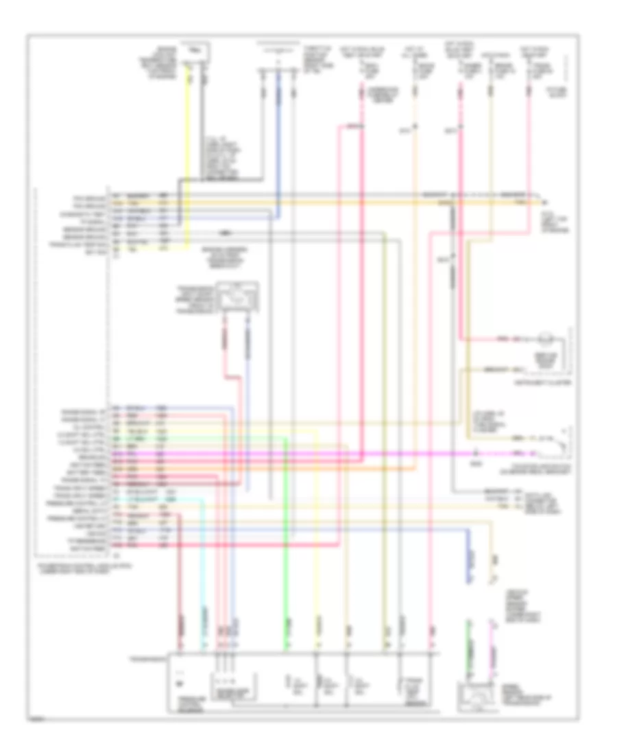
4.3L (VIN Z), Engine Performance Wiring Diagrams, M/T (1 of 3) for GMC Pickup K1995 2500
List of elements for 4.3L (VIN Z), Engine Performance Wiring Diagrams, M/T (1 of 3) for GMC Pickup K1995 2500:
- (left top front
- 12v battery
- 12v ignition
- 5v return a
- 5v return b
- 5v sensor ref
- 7.4l only
- A/c on signal in
- A10
- A11
- A12
- A13
- A14
- A15
- A16
- Air condition- ing system
- B10
- B11
- B12
- B13
- B14
- B15
- B16
- Coolant temp sensor
- Cruise control system
- Cruise ind reg grd
- Distributor ref hi
- Distributor ref lo
- Dlc
- Dlc serial data
- E10
- E11
- E12
- E13
- E14
- E15
- E16
- Ecm-i mini fuse 20a
- Egr valve solenoid
- Egr valve solenoid (4.3l only) (right side of engine)
- Elec fuel pump in
- Eng-i mini fuse 20a
- Evap canister purge ctrl
- Evaporative canister purge solenoid (7.4l only) (right side of engine)
- F10
- F11
- F12
- F13
- F14
- F15
- F16
- Fuel pump relay ctrl
- G110
- G110 (left top front of engine)
- Hot in run or start
- Idle air control unit (right rear of tbi unit)
- Idle speed control
- Ignition bypass
- Ignition control (ic)
- Knock sensor in
- Lo side inj a
- Lo side inj b
- Map sensor in
- Mil indicator ctrl
- Of engine)
- Oxygen sensor hi
- Oxygen sensor lo
- Pintle position signal
- Pnk
- Powertrain control module (under right side of i/p)
- Shift lamp control
- Stepper coil a hi
- Stepper coil a lo
- Stepper coil b hi
- Stepper coil b lo
- System ground
- Tan
- Throttle body fuel injector #1 (top of throttle body unit)
- Throttle body fuel injector #2 (top of throttle body unit)
- Throttle position sensor in
- Underhood fuse/relay center (left rear of engine comp't)
- Vss buffer signal
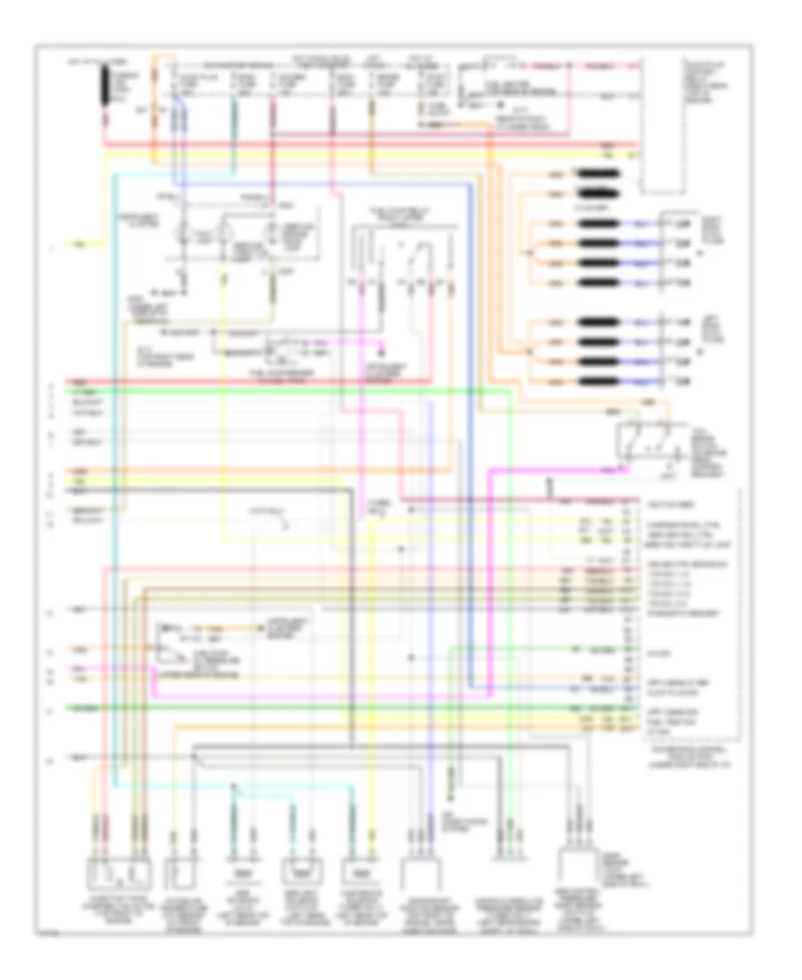
4.3L (VIN Z), Engine Performance Wiring Diagrams, M/T (2 of 3) for GMC Pickup K1995 2500
List of elements for 4.3L (VIN Z), Engine Performance Wiring Diagrams, M/T (2 of 3) for GMC Pickup K1995 2500:
- (4.3l only)
- (center rear
- Accy
- Bulb test
- Distributor
- Engine coolant temperature sensor (front of engine)
- Gauges fuse 4 10a
- Hot at all times
- Hot in run, bulb test, or start
- I/p fuse block (behind left side of i/p)
- Ignition coil (center rear of engine)
- Ignition switch
- Instrument cluster
- Knock sensor (4.3l only) (rear of engine)
- Knock sensor (right side of engine, below exhaust manifold)
- Linear egr valve (7.4l only) (right side top of engine)
- Lock
- Manifold absolute pressure sensor (right rear top of engine)
- Nca
- Of engine)
- Off
- Pnk
- Run
- Service engine soon indicator
- Start
- Tachometer test lead
- Tan
- Throttle position sensor (right side of throttle body)
- Upshift lamp
4.3L (VIN Z), Engine Performance Wiring Diagrams, M/T (3 of 3) for GMC Pickup K1995 2500
List of elements for 4.3L (VIN Z), Engine Performance Wiring Diagrams, M/T (3 of 3) for GMC Pickup K1995 2500:
- 4.3l only
- C11
- C12
- C13
- C15
- Cluster
- Data link connector (under left side of i/p)
- Ecm-b mini fuse 20a
- Fuel pump and sender
- Fuel pump oil pressure switch (top rear of engine, near distributor)
- Fuel pump prime conn- ector
- Fuel pump relay (underhood fuse/relay center)
- G103 (right front wheelhouse)
- G110 (left top front of engine)
- G117 (rear of right cylinder head)
- Heated oxygen sensor (in exhaust y-pipe)
- Hot at all times
- Idle speed control actuator solenoid (7.4l only) (side of throttle body unit)
- Instrument
- Oil press in
- Pnk
- Red
- Tach in
- Tan
- Underhood fuse/relay center (left rear of engine comp't)
- Vehicle speed sensor (left rear side of transmission)
- Vehicle speed sensor buffer (under right end of i/p)
- Vss in
5.0L
5.0L (VIN H), Engine Performance Wiring Diagrams, A/T (1 of 3) for GMC Pickup K1995 2500
List of elements for 5.0L (VIN H), Engine Performance Wiring Diagrams, A/T (1 of 3) for GMC Pickup K1995 2500:
- (4l60e)
- (4l80e)
- (left top front
- 12v battery
- 12v ignition
- 4wd engaged input
- 5v return a
- 5v return b
- 5v sensor ref
- A/c on signal in
- A10
- A11
- A12
- A13
- A14
- A15
- A16
- Air condition- ing system
- B10
- B11
- B12
- B13
- B14
- B15
- B16
- Brake sw to pcm
- Coolant temp sensor
- Cruise control system
- Cruise ind reg grd
- Distributor ref hi
- Distributor ref lo
- Dlc
- Dlc serial data
- E10
- E11
- E12
- E13
- E14
- E15
- E16
- Ecm-i mini fuse 20a
- Egr electronic vacuum regulator solenoid valve (5.7l w/ 4l80e) (right top of engine)
- Egr valve solenoid
- Egr valve solenoid (4.3/5.0/5.7l w/ 4l60e & 4.3l w/ 4l80e) (left rear of engine)
- Elec fuel pump in
- Eng-i mini fuse 20a
- Evap canister purge ctrl
- Evaporative canister purge solenoid (5.0 & 5.7l w/ 4l60e & 4.3l w/ 4l60e & calif emissions) (right side of engine)
- F10
- F11
- F12
- F13
- F14
- F15
- F16
- Fuel pump relay ctrl
- G110
- G110 (left top front of engine)
- Hot in run or start
- Idle air control unit (right rear of tbi unit)
- Ignition bypass
- Ignition control (ic)
- Knock sensor in
- Lo side inj a
- Lo side inj b
- Map sensor in
- Mil indicator ctrl
- Of engine)
- Oxygen sensor hi
- Oxygen sensor lo
- Pcm to trans temp sensor
- Pcm trans force mtr hi
- Pcm trans force mtr lo
- Pcm trans range a
- Pcm trans range b
- Pcm trans range c
- Pcm trans shift sol a
- Pcm trans shift sol b
- Pintle position signal
- Pnk
- Powertrain control module (under right side of i/p)
- Red
- Stepper coil a hi
- Stepper coil a lo
- Stepper coil b hi
- Stepper coil b lo
- System ground
- Tan
- Tcc clutch ctrl
- Throttle body fuel injector #1 (top of throttle body unit)
- Throttle body fuel injector #2 (top of throttle body unit)
- Throttle position sensor in
- Trans input speed in hi
- Trans input speed in lo
- Trans shift 3/2 solenoid (4l60e only)
- Transmission input shaft speed sensor (4l80e only) (left side of trans- mission)
- Transmissions system
- Underhood fuse/relay center (left rear of engine comp't)
- Vss buffer signal
5.0L (VIN H), Engine Performance Wiring Diagrams, A/T (2 of 3) for GMC Pickup K1995 2500
List of elements for 5.0L (VIN H), Engine Performance Wiring Diagrams, A/T (2 of 3) for GMC Pickup K1995 2500:
- (4.3l only)
- (center rear
- Accy
- Brake fuse 18 10a
- Bulb test
- Distributor
- Engine coolant temperature sensor (front of engine)
- Gauges fuse 4 10a
- Hot at all times
- Hot in run
- Hot in run, bulb test, or start
- I/p fuse block (behind left side of i/p)
- Ignition coil (center rear of engine)
- Ignition switch
- Instrument cluster
- Knock sensor (4.3l only) (rear of engine)
- Knock sensor (right side of engine, below exhaust manifold)
- Linear egr valve (4.3l w/ 4l60e & calif emiss. only) (right side top of engine)
- Lock
- Manifold absolute pressure sensor (right rear top of engine)
- Nca
- Of engine)
- Off
- Pnk
- Red
- Run
- Service engine soon indicator
- Start
- Tachometer test lead
- Tan
- Tcc/brake switch (top of brake pedal bracket)
- Throttle position sensor (right side of throttle body)
5.0L (VIN H), Engine Performance Wiring Diagrams, A/T (3 of 3) for GMC Pickup K1995 2500
List of elements for 5.0L (VIN H), Engine Performance Wiring Diagrams, A/T (3 of 3) for GMC Pickup K1995 2500:
- (4l60e
- (4l60e) t
- (4l80e) s
- 3-2 shift solenoid (4l60e only)
- All except 5.7l w/ 4l80e trans
- C11
- C12
- C13
- C15
- Cluster
- Data link connector (under left side of i/p)
- Ecm-b mini fuse 20a
- Electronic 4-speed automatic overdrive transmission
- Fuel pump and sender
- Fuel pump oil pressure switch (top rear of engine, near distributor)
- Fuel pump prime conn- ector
- Fuel pump relay (underhood fuse/relay center)
- G103 (right front wheelhouse)
- G110 (left top front of engine)
- Heated oxygen sensor (in exhaust y-pipe)
- Hot at all times
- Hot in run or start
- I/p fuse block (behind left side of i/p)
- Instrument
- Oil press in
- Only)
- Pnk
- Pressure control solenoid
- Range mode selector
- Red
- Shift sole- noid 1-2
- Shift solenoid 2-3
- Tach in
- Tan
- Torque converter clutch solenoid
- Trans fuse 20 10a
- Trans- mission temp sensor
- Underhood fuse/relay center (left rear of engine comp't)
- Vehicle speed sensor (left rear side of transmission)
- Vehicle speed sensor buffer (under right end of i/p)
- Vss in
- W/ 4l60e
- W/ 4l80e
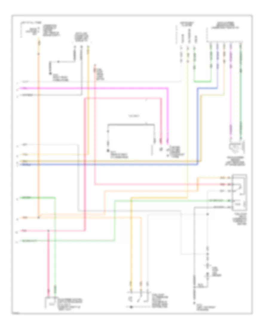
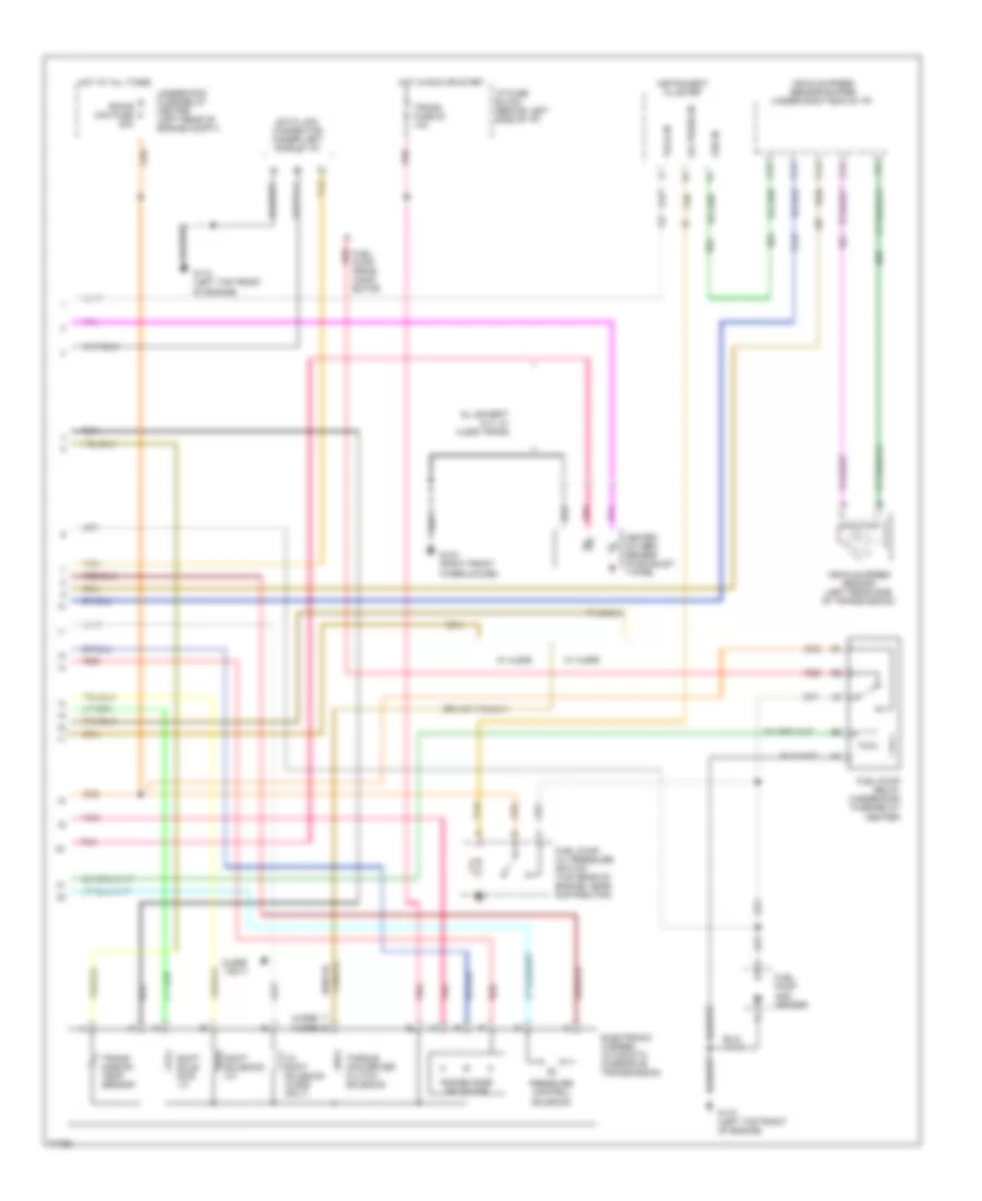
5.0L (VIN H), Engine Performance Wiring Diagrams, M/T (1 of 2) for GMC Pickup K1995 2500
List of elements for 5.0L (VIN H), Engine Performance Wiring Diagrams, M/T (1 of 2) for GMC Pickup K1995 2500:
- (5.7l h/d only)
- (a/c compressor clutch)
- 12v battery
- 12v ignition
- 5v sensor ref
- A/c on signal in
- A10
- A11
- A12
- Air conditioning system
- B10
- B11
- B12
- C10
- C11
- C12
- C13
- C14
- C15
- C16
- Coolant temp sens sig
- Crank fuse 8 10a
- Crank signal
- D10
- D11
- D12
- D13
- D14
- D15
- D16
- Data link connector (under left side of i/p)
- Distributor ref hi
- Distributor ref lo
- Dlc diagnostic test
- Dlc serial data
- Ecm-b mini fuse 20a
- Ecm-i mini fuse 20a
- Egr solenoid
- Eng-i mini fuse 20a
- Exhaust gas recirculation solenoid (5.0l & 5.7l l/d only) (right rear top of engine)
- Fuel pump relay ctrl
- Fuel pump signal input
- Gauges fuse 4 10a
- Hot at all times
- Hot in run or start
- Hot in run, bulb test or start
- Hot in start
- I/p fuse block
- Iac coil a hi
- Iac coil a lo
- Iac coil b hi
- Iac coil b lo
- Ic bypass
- Idle air control unit (right rear of tbi unit)
- Ign-e mini fuse 10a
- Ignition control (ic)
- Injector 1 driver
- Injector 2 driver
- Instrument cluster
- Map 5v sensor ground
- Map sensor signal
- Mil indicator ctrl
- Nca
- Oxygen sensor (right side exhaust manifold)
- Oxygen sensor ground
- Oxygen sensor signal
- Pnk
- Powertrain control module (under right side of i/p)
- Sensor return ground
- Service engine soon indicator
- Spark retard signal
- System ground
- Tan
- Throttle body fuel injector #1 (top of throttle body unit)
- Throttle body fuel injector #2 (top of throttle body unit)
- Tp sensor signal
- Underhood fuse/relay center (left rear of engine comp't)
- Up- shift lamp
- Upshift lamp ctrl
- Vss buffer signal
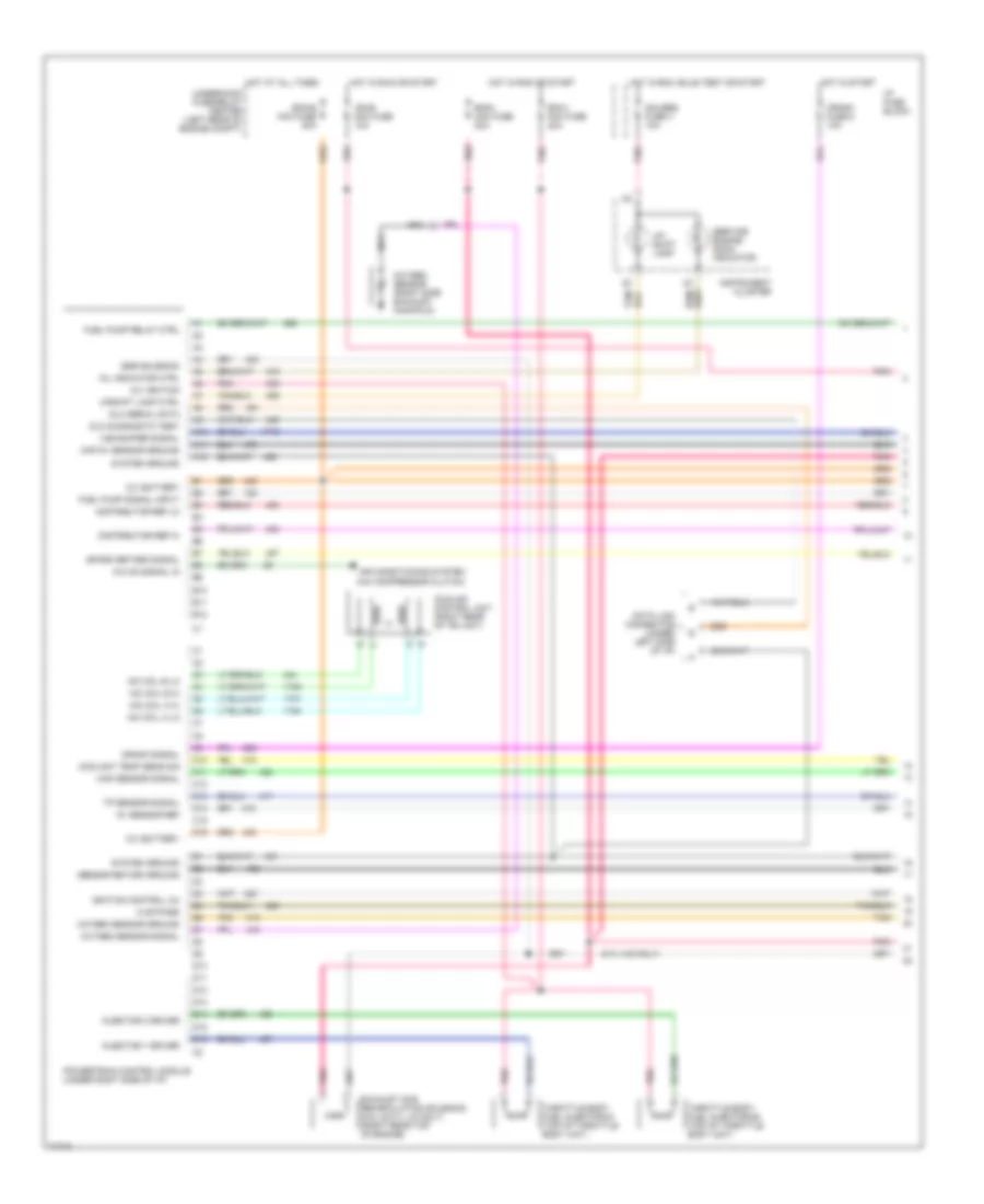
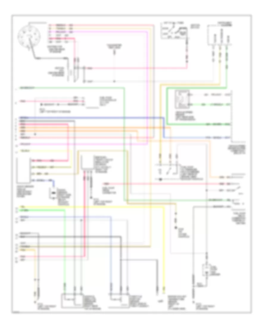
5.0L (VIN H), Engine Performance Wiring Diagrams, M/T (2 of 2) for GMC Pickup K1995 2500
List of elements for 5.0L (VIN H), Engine Performance Wiring Diagrams, M/T (2 of 2) for GMC Pickup K1995 2500:
- (center rear
- Accy
- Bulb test
- C11
- C12
- C15
- Distributor
- Egr elec- tronic vacuum regulator solenoid (5.7l h/d only) (right top of engine)
- Engine coolant temperature sensor (front of left cylinder head)
- Fuel pump and sender
- Fuel pump cycle module (5.7l h/d only)
- Fuel pump oil pressure switch/sender (left rear of engine, near exhaust manifold)
- Fuel pump prime connector
- Fuel pump relay (underhood fuse/relay center)
- G110 (left top front of engine)
- G125 (on intake manifold)
- Hot at all times
- Ignition coil (center rear of engine)
- Ignition switch
- Instrument cluster
- Knock sensor (right side of engine, below exhaust manifold)
- Knock sensor module (above right side rocker cover)
- Lock
- Manifold absolute pressure sensor (right rear top of engine)
- Nca
- Of engine)
- Off
- Oil press in
- Pnk
- Red
- Run
- Start
- Tach in
- Tachometer test lead
- Tan
- Throttle position sensor (right side of throttle body)
- Vehicle speed sensor (left rear side of transmission)
- Vehicle speed sensor buffer (under right end of i/p)
- Vss in
5.7L
5.7L (VIN K), Engine Performance Wiring Diagrams, A/T (1 of 3) for GMC Pickup K1995 2500
List of elements for 5.7L (VIN K), Engine Performance Wiring Diagrams, A/T (1 of 3) for GMC Pickup K1995 2500:
- (4l60e)
- (4l80e)
- (left top front
- 12v battery
- 12v ignition
- 4wd engaged input
- 5v return a
- 5v return b
- 5v sensor ref
- A/c on signal in
- A10
- A11
- A12
- A13
- A14
- A15
- A16
- Air condition- ing system
- B10
- B11
- B12
- B13
- B14
- B15
- B16
- Brake sw to pcm
- Coolant temp sensor
- Cruise control system
- Cruise ind reg grd
- Distributor ref hi
- Distributor ref lo
- Dlc
- Dlc serial data
- E10
- E11
- E12
- E13
- E14
- E15
- E16
- Ecm-i mini fuse 20a
- Egr electronic vacuum regulator solenoid valve (5.7l w/ 4l80e) (right top of engine)
- Egr valve solenoid
- Egr valve solenoid (4.3/5.0/5.7l w/ 4l60e & 4.3l w/ 4l80e) (left rear of engine)
- Elec fuel pump in
- Eng-i mini fuse 20a
- Evap canister purge ctrl
- Evaporative canister purge solenoid (5.0 & 5.7l w/ 4l60e & 4.3l w/ 4l60e & calif emissions) (right side of engine)
- F10
- F11
- F12
- F13
- F14
- F15
- F16
- Fuel pump relay ctrl
- G110
- G110 (left top front of engine)
- Hot in run or start
- Idle air control unit (right rear of tbi unit)
- Ignition bypass
- Ignition control (ic)
- Knock sensor in
- Lo side inj a
- Lo side inj b
- Map sensor in
- Mil indicator ctrl
- Of engine)
- Oxygen sensor hi
- Oxygen sensor lo
- Pcm to trans temp sensor
- Pcm trans force mtr hi
- Pcm trans force mtr lo
- Pcm trans range a
- Pcm trans range b
- Pcm trans range c
- Pcm trans shift sol a
- Pcm trans shift sol b
- Pintle position signal
- Pnk
- Powertrain control module (under right side of i/p)
- Red
- Stepper coil a hi
- Stepper coil a lo
- Stepper coil b hi
- Stepper coil b lo
- System ground
- Tan
- Tcc clutch ctrl
- Throttle body fuel injector #1 (top of throttle body unit)
- Throttle body fuel injector #2 (top of throttle body unit)
- Throttle position sensor in
- Trans input speed in hi
- Trans input speed in lo
- Trans shift 3/2 solenoid (4l60e only)
- Transmission input shaft speed sensor (4l80e only) (left side of trans- mission)
- Transmissions system
- Underhood fuse/relay center (left rear of engine comp't)
- Vss buffer signal
5.7L (VIN K), Engine Performance Wiring Diagrams, A/T (2 of 3) for GMC Pickup K1995 2500
List of elements for 5.7L (VIN K), Engine Performance Wiring Diagrams, A/T (2 of 3) for GMC Pickup K1995 2500:
- (4.3l only)
- (center rear
- Accy
- Brake fuse 18 10a
- Bulb test
- Distributor
- Engine coolant temperature sensor (front of engine)
- Gauges fuse 4 10a
- Hot at all times
- Hot in run
- Hot in run, bulb test, or start
- I/p fuse block (behind left side of i/p)
- Ignition coil (center rear of engine)
- Ignition switch
- Instrument cluster
- Knock sensor (4.3l only) (rear of engine)
- Knock sensor (right side of engine, below exhaust manifold)
- Linear egr valve (4.3l w/ 4l60e & calif emiss. only) (right side top of engine)
- Lock
- Manifold absolute pressure sensor (right rear top of engine)
- Nca
- Of engine)
- Off
- Pnk
- Red
- Run
- Service engine soon indicator
- Start
- Tachometer test lead
- Tan
- Tcc/brake switch (top of brake pedal bracket)
- Throttle position sensor (right side of throttle body)
5.7L (VIN K), Engine Performance Wiring Diagrams, A/T (3 of 3) for GMC Pickup K1995 2500
List of elements for 5.7L (VIN K), Engine Performance Wiring Diagrams, A/T (3 of 3) for GMC Pickup K1995 2500:
- (4l60e
- (4l60e) t
- (4l80e) s
- 3-2 shift solenoid (4l60e only)
- All except 5.7l w/ 4l80e trans
- C11
- C12
- C13
- C15
- Cluster
- Data link connector (under left side of i/p)
- Ecm-b mini fuse 20a
- Electronic 4-speed automatic overdrive transmission
- Fuel pump and sender
- Fuel pump oil pressure switch (top rear of engine, near distributor)
- Fuel pump prime conn- ector
- Fuel pump relay (underhood fuse/relay center)
- G103 (right front wheelhouse)
- G110 (left top front of engine)
- Heated oxygen sensor (in exhaust y-pipe)
- Hot at all times
- Hot in run or start
- I/p fuse block (behind left side of i/p)
- Instrument
- Oil press in
- Only)
- Pnk
- Pressure control solenoid
- Range mode selector
- Red
- Shift sole- noid 1-2
- Shift solenoid 2-3
- Tach in
- Tan
- Torque converter clutch solenoid
- Trans fuse 20 10a
- Trans- mission temp sensor
- Underhood fuse/relay center (left rear of engine comp't)
- Vehicle speed sensor (left rear side of transmission)
- Vehicle speed sensor buffer (under right end of i/p)
- Vss in
- W/ 4l60e
- W/ 4l80e
5.7L (VIN K), Engine Performance Wiring Diagrams, M/T (1 of 2) for GMC Pickup K1995 2500
List of elements for 5.7L (VIN K), Engine Performance Wiring Diagrams, M/T (1 of 2) for GMC Pickup K1995 2500:
- (5.7l h/d only)
- (a/c compressor clutch)
- 12v battery
- 12v ignition
- 5v sensor ref
- A/c on signal in
- A10
- A11
- A12
- Air conditioning system
- B10
- B11
- B12
- C10
- C11
- C12
- C13
- C14
- C15
- C16
- Coolant temp sens sig
- Crank fuse 8 10a
- Crank signal
- D10
- D11
- D12
- D13
- D14
- D15
- D16
- Data link connector (under left side of i/p)
- Distributor ref hi
- Distributor ref lo
- Dlc diagnostic test
- Dlc serial data
- Ecm-b mini fuse 20a
- Ecm-i mini fuse 20a
- Egr solenoid
- Eng-i mini fuse 20a
- Exhaust gas recirculation solenoid (5.0l & 5.7l l/d only) (right rear top of engine)
- Fuel pump relay ctrl
- Fuel pump signal input
- Gauges fuse 4 10a
- Hot at all times
- Hot in run or start
- Hot in run, bulb test or start
- Hot in start
- I/p fuse block
- Iac coil a hi
- Iac coil a lo
- Iac coil b hi
- Iac coil b lo
- Ic bypass
- Idle air control unit (right rear of tbi unit)
- Ign-e mini fuse 10a
- Ignition control (ic)
- Injector 1 driver
- Injector 2 driver
- Instrument cluster
- Map 5v sensor ground
- Map sensor signal
- Mil indicator ctrl
- Nca
- Oxygen sensor (right side exhaust manifold)
- Oxygen sensor ground
- Oxygen sensor signal
- Pnk
- Powertrain control module (under right side of i/p)
- Sensor return ground
- Service engine soon indicator
- Spark retard signal
- System ground
- Tan
- Throttle body fuel injector #1 (top of throttle body unit)
- Throttle body fuel injector #2 (top of throttle body unit)
- Tp sensor signal
- Underhood fuse/relay center (left rear of engine comp't)
- Up- shift lamp
- Upshift lamp ctrl
- Vss buffer signal
5.7L (VIN K), Engine Performance Wiring Diagrams, M/T (2 of 2) for GMC Pickup K1995 2500
List of elements for 5.7L (VIN K), Engine Performance Wiring Diagrams, M/T (2 of 2) for GMC Pickup K1995 2500:
- (center rear
- Accy
- Bulb test
- C11
- C12
- C15
- Distributor
- Egr elec- tronic vacuum regulator solenoid (5.7l h/d only) (right top of engine)
- Engine coolant temperature sensor (front of left cylinder head)
- Fuel pump and sender
- Fuel pump cycle module (5.7l h/d only)
- Fuel pump oil pressure switch/sender (left rear of engine, near exhaust manifold)
- Fuel pump prime connector
- Fuel pump relay (underhood fuse/relay center)
- G110 (left top front of engine)
- G125 (on intake manifold)
- Hot at all times
- Ignition coil (center rear of engine)
- Ignition switch
- Instrument cluster
- Knock sensor (right side of engine, below exhaust manifold)
- Knock sensor module (above right side rocker cover)
- Lock
- Manifold absolute pressure sensor (right rear top of engine)
- Nca
- Of engine)
- Off
- Oil press in
- Pnk
- Red
- Run
- Start
- Tach in
- Tachometer test lead
- Tan
- Throttle position sensor (right side of throttle body)
- Vehicle speed sensor (left rear side of transmission)
- Vehicle speed sensor buffer (under right end of i/p)
- Vss in
6.5L
6.5L (VIN F), Engine Performance Wiring Diagrams, 4L80-E A/T (1 of 2) for GMC Pickup K1995 2500
List of elements for 6.5L (VIN F), Engine Performance Wiring Diagrams, 4L80-E A/T (1 of 2) for GMC Pickup K1995 2500:
- 1-2 shift sol
- 1-2 shift sol ctrl
- 2-3 shift sol
- 2-3 shift sol ctrl
- 4 wheel drive low switch
- 4wd fuse 25a
- 5v ref
- A range mode selector
- Accelerator pedal position (app) module (top of accelerator bracket)
- Anti-lock brakes system
- App 1 sens 5v ref
- App 1 sens gnd
- App 1 sensor
- App 2 sens gnd
- App 2 sensor
- App 3 sens 5v ref
- App 3 sens gnd
- App 3 sensor
- App sens 1 sig
- App sens 2 sig
- B/h
- Battery feed
- Boost sig
- C10
- C11
- C12
- C13
- C14
- C15
- C16
- Ckp sig
- Closure sig
- Crank fuse 10a
- Cruise control system
- Cruise on/off sig
- D10
- D11
- D12
- D13
- D14
- D15
- D16
- Data link connector (under left side of i/p)
- Ecm-b fuse 20a
- Ect sig
- Egr ctrl/baro sig
- Egr sol ctrl
- Electronic 4-speed automatic overdrive transmission
- Eng shut-off ctrl
- Engine coolant temperature (ect) sensor (right side of engine)
- Engine shut- off solenoid (top front of engine)
- Fuel inj ctrl
- Fuel inj sig
- Fuel sol fuse 20a
- Fuel solenoid (top front of engine)
- Fuel solenoid driver (top front of engine)
- Fuse block
- Fwd low sw
- G117 (top right rear of engine)
- Glow plug rly ctrl
- Hi resolution sig
- Hot at all times
- Hot in crank
- Hot in run
- Hot in start or run
- Mil
- Optical sens 5v ref
- Optical sens cam sig
- Optical sens gnd
- Optical sensor and fuel temper- ature sensor (top front of engine)
- Pnk
- Powertrain control module (pcm) (under right end of i/p)
- Press ctrl sol
- Press ctrl sol (lo)
- Pressure control sol
- Range signal a
- Range signal b
- Range signal c
- Red
- Resume/accel sig
- Sensor gnd
- Serial data
- Set/coast sig
- Speed sensor (left rear side of transmission)
- System gnd
- Tan
- Tcc brake sw
- Tcc sol
- Tcc sol ctrl (pwm)
- Trans fluid temp (tft) sensor
- Trans fluid temp sig
- Trans fuse 10a
- Trans input spd (hi)
- Trans input spd sig
- Trans output
- Trans output spd sig
- Transmission input speed sensor
- Turbo only
- Vehicle speed sensor buffer (under right end of i/p)
- Vin p only
- Vss
- Vss input
- Vss output
6.5L (VIN F), Engine Performance Wiring Diagrams, 4L80-E A/T (2 of 2) for GMC Pickup K1995 2500
List of elements for 6.5L (VIN F), Engine Performance Wiring Diagrams, 4L80-E A/T (2 of 2) for GMC Pickup K1995 2500:
- "service engine soon" lamp
- "service throttle" lamp
- (left rear top of engine)
- (rear of right cylinder head)
- (turbo only)
- (under left side of i/p, near dlc)
- (upper rear of engine)
- A/c sig
- A10
- A11
- A12
- Air conditioning system
- App 2 sens 5v ref
- App 3 sens sig
- B/h
- B10
- B11
- B12
- B2 red
- Baro sensor (vin f) (upper left side of cowl)
- Brake fuse 10a
- C203
- Crankshaft position sensor (top front of engine, inside
- Cruise ctrl brake sig
- Diagnostic request
- Ecm-i fuse 20a
- Egr control pressure/ baro sensor (vin p & s) (upper left side of cowl)
- Egr solenoid (vin p) (left rear top of engine)
- Egr vent sol ctrl
- Egr vent solenoid (vin p & s)
- Eng-i fuse 20a
- Fuel pump oil pressure switch
- Fuel pump relay (right upper cowl)
- Fuel pump/sender (in fuel tank)
- Fuel temp sig
- Fuse block
- Fusible link (12ga-
- Fusible links
- G117
- G117 (top right rear of engine)
- G206
- Gauges fuse 10a
- Glow plug control relay (right rear top of engine)
- Glow plug fuse 10a
- Glow plug sig
- Hot at all times
- Hot in run
- Hot in run, bulb
- Hot in start or run
- Iat sig
- Ignition feed
- Injection pump)
- Injection timing stepper (its) motor (top front of engine)
- Instrument cluster
- Instrument clusters system
- Intake air temperature (iat) sensor (at front of engine)
- Its coil 1 hi
- Its coil 1 lo
- Its coil 2 hi
- Its coil 2 lo
- Left bank glow plugs
- Manifold absolute pressure sensor (turbo only) (left rear engine compt, at cowl)
- Powertrain control module (pcm) (under right end of i/p)
- Red
- Right bank glow plugs
- Stop fuse 15a
- Tan
- Tcc/ brake switch (on brake pedal support bracket)
- Test or start
- Vin p only
- Wait lamp
- Wastegate sol ctrl
- Wastegate solenoid (turbo only) (left rear top of engine)
6.5L (VIN F), Engine Performance Wiring Diagrams, M/T (1 of 2) for GMC Pickup K1995 2500
List of elements for 6.5L (VIN F), Engine Performance Wiring Diagrams, M/T (1 of 2) for GMC Pickup K1995 2500:
- 4 wheel drive low switch
- 4wd fuse 25a
- 4wd low sw
- 5v ref
- Accelerator pedal position (app) module (top of accelerator bracket)
- Anti-lock brakes system
- App 1 sens 5v ref
- App 1 sens gnd
- App 1 sensor
- App 2 sens gnd
- App 2 sensor
- App 3 sens 5v ref
- App 3 sens gnd
- App 3 sensor
- App sens 1 sig
- App sens 2 sig
- Battery feed
- Boost sig
- C10
- C11
- C12
- C13
- C14
- C15
- C16
- Ckp sig
- Closure gnd
- Clutch pedal position switch
- Conven- ience center
- Crank fuse 10a
- Cruise control system
- Cruise on/off sig
- D10
- D11
- D12
- D13
- D14
- D15
- D16
- Data link connector (under left side of i/p)
- Ecm-b fuse 20a
- Ect sig
- Egr ctrl/baro sig
- Egr sol ctrl
- Eng shut-off ctrl
- Engine coolant temperature (ect) sensor (right side of engine)
- Engine shut- off solenoid (top front of engine)
- Fuel inj ctrl
- Fuel inj sig
- Fuel sol fuse 20a
- Fuel solenoid (top front of engine)
- Fuel solenoid driver (top front of engine)
- Fuse block
- G117 (top right rear of engine)
- Glow plug rly ctrl
- Hi resolution sig
- Hot at all times
- Hot in crank
- Hot in run
- Hot in start
- Mil
- Optical sens 5v ref
- Optical sens cam sig
- Optical sens gnd
- Optical/ fuel temp sensor (top front of engine)
- Or run
- Pnk
- Powertrain control module (pcm) (under right end of i/p)
- Red
- Resume/accel sig
- Sensor gnd
- Serial data
- Set/coast sig
- Speed sensor (left rear side of transmission)
- System gnd
- Tan
- Tcc brake sw
- Trans fluid temp sig
- Trans output
- Trans output spd sig
- Vehicle speed sensor buffer (under right end of i/p)
- Vss
- Vss input
- Vss output
6.5L (VIN F), Engine Performance Wiring Diagrams, M/T (2 of 2) for GMC Pickup K1995 2500
List of elements for 6.5L (VIN F), Engine Performance Wiring Diagrams, M/T (2 of 2) for GMC Pickup K1995 2500:
- "service engine soon" lamp
- "service throttle" lamp
- (left rear top of engine)
- (rear of right cylinder head)
- (turbo only)
- (under left side of i/p, near dlc)
- (upper rear of engine)
- A/c sig
- A10
- A11
- A12
- Air conditioning system
- App 2 sens 5v ref
- App 3 sens sig
- B/h
- B10
- B11
- B12
- B2 red
- Baro sensor (vin f) (upper left side of cowl)
- Brake fuse 10a
- C203
- Crankshaft position sensor (top front of engine, inside
- Cruise ctrl brake sig
- Diagnostic request
- Ecm-i fuse 20a
- Egr control pressure/ baro sensor (vin p & s) (upper left side of cowl)
- Egr solenoid (vin p) (left rear top of engine)
- Egr vent sol ctrl
- Egr vent solenoid (vin p & s)
- Eng-i fuse 20a
- Fuel pump oil pressure switch
- Fuel pump relay (right upper cowl)
- Fuel pump/sender (in fuel tank)
- Fuel temp sig
- Fuse block
- Fusible link (12ga-
- Fusible links
- G117
- G117 (top right rear of engine)
- G206
- Gauges fuse 10a
- Glow plug control relay (right rear top of engine)
- Glow plug fuse 10a
- Glow plug sig
- Hot at all times
- Hot in run
- Hot in run, bulb
- Hot in start or run
- Iat sig
- Ignition feed
- Injection pump)
- Injection timing stepper (its) motor (top front of engine)
- Instrument cluster
- Instrument clusters system
- Intake air temperature (iat) sensor (at front of engine)
- Its coil 1 hi
- Its coil 1 lo
- Its coil 2 hi
- Its coil 2 lo
- Left bank glow plugs
- Manifold absolute pressure sensor (turbo only) (left rear engine compt, at cowl)
- Powertrain control module (pcm) (under right end of i/p)
- Red
- Right bank glow plugs
- Stop fuse 15a
- Tan
- Tcc/ brake switch (on brake pedal support bracket)
- Test or start
- Vin p only
- Wait lamp
- Wastegate sol ctrl
- Wastegate solenoid (turbo only) (left rear top of engine)
6.5L (VIN P), Engine Performance Wiring Diagrams, 4L60-E A/T (1 of 2) for GMC Pickup K1995 2500
List of elements for 6.5L (VIN P), Engine Performance Wiring Diagrams, 4L60-E A/T (1 of 2) for GMC Pickup K1995 2500:
- 1-2 shift sol
- 1-2 shift sol ctrl
- 2-3 shift sol
- 2-3 shift sol ctrl
- 3-2 shift sol
- 4 wheel drive low switch
- 4wd fuse 25a
- 5v ref
- A range mode selector
- Accelerator pedal position (app) module (top of accelerator bracket)
- Anti-lock brakes system
- App 1 sens 5v ref
- App 1 sens gnd
- App 1 sensor
- App 2 sens gnd
- App 2 sensor
- App 3 sens 5v ref
- App 3 sens gnd
- App 3 sensor
- App sens 1 sig
- App sens 2 sig
- B/h
- Battery feed
- Boost sig
- C10
- C11
- C12
- C13
- C14
- C15
- C16
- Ckp sig
- Closure sig
- Crank fuse 10a
- Cruise control system
- Cruise on/off sig
- D10
- D11
- D12
- D13
- D14
- D15
- D16
- Data link connector (under left side of i/p)
- Ecm-b fuse 20a
- Ect sig
- Egr ctrl/baro sig
- Egr sol ctrl
- Electronic 4-speed automatic overdrive transmission
- Eng shut-off ctrl
- Engine coolant temperature (ect) sensor (right side of engine)
- Engine shut- off solenoid (top front of engine)
- Fuel inj ctrl
- Fuel inj sig
- Fuel sol fuse 20a
- Fuel solenoid (top front of engine)
- Fuel solenoid driver (top front of engine)
- Fuse block
- Fwd low sw
- G117 (top right rear of engine)
- Glow plug rly ctrl
- Hi resolution sig
- Hot at all times
- Hot in crank
- Hot in run
- Hot in start or run
- Mil
- Optical sens 5v ref
- Optical sens cam sig
- Optical sens gnd
- Optical/ fuel temp sensor (top front of engine)
- Pnk
- Powertrain control module (pcm) (under right end of i/p)
- Press ctrl sol
- Press ctrl sol (lo)
- Pressure control sol
- Range signal a
- Range signal b
- Range signal c
- Red
- Resume/accel sig
- Sensor gnd
- Serial data
- Set/coast sig
- Speed sensor (left rear side of transmission)
- System gnd
- Tan
- Tcc brake sw
- Tcc pwm sol
- Tcc pwm sol ctrl
- Tcc sol
- Tcc sol ctrl
- Trans fluid temp (tft) sensor
- Trans fluid temp sig
- Trans fuse 10a
- Trans output
- Trans output spd sig
- Turbo only
- Vehicle speed sensor buffer (under right end of i/p)
- Vin p only
- Vss
- Vss input
- Vss output
6.5L (VIN P), Engine Performance Wiring Diagrams, 4L60-E A/T (2 of 2) for GMC Pickup K1995 2500
List of elements for 6.5L (VIN P), Engine Performance Wiring Diagrams, 4L60-E A/T (2 of 2) for GMC Pickup K1995 2500:
- "service engine soon" lamp
- "service throttle" lamp
- (left rear top of engine)
- (rear of right cylinder head)
- (turbo only)
- (under left side of i/p, near dlc)
- (upper rear of engine)
- 2-3 shift sol ctrl
- A/c sig
- A10
- A11
- A12
- Air conditioning system
- App 2 sens 5v ref
- App 3 sens sig
- B/h
- B10
- B11
- B12
- B2 red
- Baro sensor (vin f) (upper left side of cowl)
- Brake fuse 10a
- C203
- Crankshaft position sensor (top front of engine, inside
- Cruise ctrl brake sig
- Diagnostic request
- Ecm-i fuse 20a
- Egr control pressure/ baro sensor (vin p & s) (upper left side of cowl)
- Egr solenoid (vin p) (left rear top of engine)
- Egr vent sol ctrl
- Egr vent solenoid (vin p & s)
- Eng-i fuse 20a
- Fuel pump oil pressure switch
- Fuel pump relay (right upper cowl)
- Fuel pump/sender (in fuel tank)
- Fuel temp sig
- Fuse block
- Fusible link (12ga-
- Fusible links
- G117
- G117 (top right rear of engine)
- G206
- Gauges fuse 10a
- Glow plug control relay (right rear top of engine)
- Glow plug fuse 10a
- Glow plug sig
- Hot at all times
- Hot in run
- Hot in run, bulb
- Hot in start or run
- Iat sig
- Ignition feed
- Injection pump)
- Injection timing stepper (its) motor (top front of engine)
- Instrument cluster
- Instrument clusters system
- Intake air temperature (iat) sensor (at front of engine)
- Its coil 1 hi
- Its coil 1 lo
- Its coil 2 hi
- Its coil 2 lo
- Left bank glow plugs
- Manifold absolute pressure sensor (turbo only) (left rear engine compt, at cowl)
- Powertrain control module (pcm) (under right end of i/p)
- Red
- Right bank glow plugs
- Stop fuse 15a
- Tan
- Tcc/ brake switch (on brake pedal support bracket)
- Test or start
- Vin p only
- Wait lamp
- Wastegate sol ctrl
- Wastegate solenoid (turbo only) (left rear top of engine)
6.5L (VIN P), Engine Performance Wiring Diagrams, M/T (1 of 2) for GMC Pickup K1995 2500
List of elements for 6.5L (VIN P), Engine Performance Wiring Diagrams, M/T (1 of 2) for GMC Pickup K1995 2500:
- 4 wheel drive low switch
- 4wd fuse 25a
- 4wd low sw
- 5v ref
- Accelerator pedal position (app) module (top of accelerator bracket)
- Anti-lock brakes system
- App 1 sens 5v ref
- App 1 sens gnd
- App 1 sensor
- App 2 sens gnd
- App 2 sensor
- App 3 sens 5v ref
- App 3 sens gnd
- App 3 sensor
- App sens 1 sig
- App sens 2 sig
- Battery feed
- Boost sig
- C10
- C11
- C12
- C13
- C14
- C15
- C16
- Ckp sig
- Closure gnd
- Clutch pedal position switch
- Conven- ience center
- Crank fuse 10a
- Cruise control system
- Cruise on/off sig
- D10
- D11
- D12
- D13
- D14
- D15
- D16
- Data link connector (under left side of i/p)
- Ecm-b fuse 20a
- Ect sig
- Egr ctrl/baro sig
- Egr sol ctrl
- Eng shut-off ctrl
- Engine coolant temperature (ect) sensor (right side of engine)
- Engine shut- off solenoid (top front of engine)
- Fuel inj ctrl
- Fuel inj sig
- Fuel sol fuse 20a
- Fuel solenoid (top front of engine)
- Fuel solenoid driver (top front of engine)
- Fuse block
- G117 (top right rear of engine)
- Glow plug rly ctrl
- Hi resolution sig
- Hot at all times
- Hot in crank
- Hot in run
- Hot in start
- Mil
- Optical sens 5v ref
- Optical sens cam sig
- Optical sens gnd
- Optical/ fuel temp sensor (top front of engine)
- Or run
- Pnk
- Powertrain control module (pcm) (under right end of i/p)
- Red
- Resume/accel sig
- Sensor gnd
- Serial data
- Set/coast sig
- Speed sensor (left rear side of transmission)
- System gnd
- Tan
- Tcc brake sw
- Trans fluid temp sig
- Trans output
- Trans output spd sig
- Vehicle speed sensor buffer (under right end of i/p)
- Vss
- Vss input
- Vss output
6.5L (VIN P), Engine Performance Wiring Diagrams, M/T (2 of 2) for GMC Pickup K1995 2500
List of elements for 6.5L (VIN P), Engine Performance Wiring Diagrams, M/T (2 of 2) for GMC Pickup K1995 2500:
- "service engine soon" lamp
- "service throttle" lamp
- (left rear top of engine)
- (rear of right cylinder head)
- (turbo only)
- (under left side of i/p, near dlc)
- (upper rear of engine)
- A/c sig
- A10
- A11
- A12
- Air conditioning system
- App 2 sens 5v ref
- App 3 sens sig
- B/h
- B10
- B11
- B12
- B2 red
- Baro sensor (vin f) (upper left side of cowl)
- Brake fuse 10a
- C203
- Crankshaft position sensor (top front of engine, inside
- Cruise ctrl brake sig
- Diagnostic request
- Ecm-i fuse 20a
- Egr control pressure/ baro sensor (vin p & s) (upper left side of cowl)
- Egr solenoid (vin p) (left rear top of engine)
- Egr vent sol ctrl
- Egr vent solenoid (vin p & s)
- Eng-i fuse 20a
- Fuel pump oil pressure switch
- Fuel pump relay (right upper cowl)
- Fuel pump/sender (in fuel tank)
- Fuel temp sig
- Fuse block
- Fusible link (12ga-
- Fusible links
- G117
- G117 (top right rear of engine)
- G206
- Gauges fuse 10a
- Glow plug control relay (right rear top of engine)
- Glow plug fuse 10a
- Glow plug sig
- Hot at all times
- Hot in run
- Hot in run, bulb
- Hot in start or run
- Iat sig
- Ignition feed
- Injection pump)
- Injection timing stepper (its) motor (top front of engine)
- Instrument cluster
- Instrument clusters system
- Intake air temperature (iat) sensor (at front of engine)
- Its coil 1 hi
- Its coil 1 lo
- Its coil 2 hi
- Its coil 2 lo
- Left bank glow plugs
- Manifold absolute pressure sensor (turbo only) (left rear engine compt, at cowl)
- Powertrain control module (pcm) (under right end of i/p)
- Red
- Right bank glow plugs
- Stop fuse 15a
- Tan
- Tcc/ brake switch (on brake pedal support bracket)
- Test or start
- Vin p only
- Wait lamp
- Wastegate sol ctrl
- Wastegate solenoid (turbo only) (left rear top of engine)
6.5L (VIN S), Engine Performance Wiring Diagrams, 4L80-E A/T (1 of 2) for GMC Pickup K1995 2500
List of elements for 6.5L (VIN S), Engine Performance Wiring Diagrams, 4L80-E A/T (1 of 2) for GMC Pickup K1995 2500:
- 1-2 shift sol
- 1-2 shift sol ctrl
- 2-3 shift sol
- 2-3 shift sol ctrl
- 4 wheel drive low switch
- 4wd fuse 25a
- 5v ref
- A range mode selector
- Accelerator pedal position (app) module (top of accelerator bracket)
- Anti-lock brakes system
- App 1 sens 5v ref
- App 1 sens gnd
- App 1 sensor
- App 2 sens gnd
- App 2 sensor
- App 3 sens 5v ref
- App 3 sens gnd
- App 3 sensor
- App sens 1 sig
- App sens 2 sig
- B/h
- Battery feed
- Boost sig
- C10
- C11
- C12
- C13
- C14
- C15
- C16
- Ckp sig
- Closure sig
- Crank fuse 10a
- Cruise control system
- Cruise on/off sig
- D10
- D11
- D12
- D13
- D14
- D15
- D16
- Data link connector (under left side of i/p)
- Ecm-b fuse 20a
- Ect sig
- Egr ctrl/baro sig
- Egr sol ctrl
- Electronic 4-speed automatic overdrive transmission
- Eng shut-off ctrl
- Engine coolant temperature (ect) sensor (right side of engine)
- Engine shut- off solenoid (top front of engine)
- Fuel inj ctrl
- Fuel inj sig
- Fuel sol fuse 20a
- Fuel solenoid (top front of engine)
- Fuel solenoid driver (top front of engine)
- Fuse block
- Fwd low sw
- G117 (top right rear of engine)
- Glow plug rly ctrl
- Hi resolution sig
- Hot at all times
- Hot in crank
- Hot in run
- Hot in start or run
- Mil
- Optical sens 5v ref
- Optical sens cam sig
- Optical sens gnd
- Optical sensor and fuel temper- ature sensor (top front of engine)
- Pnk
- Powertrain control module (pcm) (under right end of i/p)
- Press ctrl sol
- Press ctrl sol (lo)
- Pressure control sol
- Range signal a
- Range signal b
- Range signal c
- Red
- Resume/accel sig
- Sensor gnd
- Serial data
- Set/coast sig
- Speed sensor (left rear side of transmission)
- System gnd
- Tan
- Tcc brake sw
- Tcc sol
- Tcc sol ctrl (pwm)
- Trans fluid temp (tft) sensor
- Trans fluid temp sig
- Trans fuse 10a
- Trans input spd (hi)
- Trans input spd sig
- Trans output
- Trans output spd sig
- Transmission input speed sensor
- Turbo only
- Vehicle speed sensor buffer (under right end of i/p)
- Vin p only
- Vss
- Vss input
- Vss output
6.5L (VIN S), Engine Performance Wiring Diagrams, 4L80-E A/T (2 of 2) for GMC Pickup K1995 2500
List of elements for 6.5L (VIN S), Engine Performance Wiring Diagrams, 4L80-E A/T (2 of 2) for GMC Pickup K1995 2500:
- "service engine soon" lamp
- "service throttle" lamp
- (left rear top of engine)
- (rear of right cylinder head)
- (turbo only)
- (under left side of i/p, near dlc)
- (upper rear of engine)
- A/c sig
- A10
- A11
- A12
- Air conditioning system
- App 2 sens 5v ref
- App 3 sens sig
- B/h
- B10
- B11
- B12
- B2 red
- Baro sensor (vin f) (upper left side of cowl)
- Brake fuse 10a
- C203
- Crankshaft position sensor (top front of engine, inside
- Cruise ctrl brake sig
- Diagnostic request
- Ecm-i fuse 20a
- Egr control pressure/ baro sensor (vin p & s) (upper left side of cowl)
- Egr solenoid (vin p) (left rear top of engine)
- Egr vent sol ctrl
- Egr vent solenoid (vin p & s)
- Eng-i fuse 20a
- Fuel pump oil pressure switch
- Fuel pump relay (right upper cowl)
- Fuel pump/sender (in fuel tank)
- Fuel temp sig
- Fuse block
- Fusible link (12ga-
- Fusible links
- G117
- G117 (top right rear of engine)
- G206
- Gauges fuse 10a
- Glow plug control relay (right rear top of engine)
- Glow plug fuse 10a
- Glow plug sig
- Hot at all times
- Hot in run
- Hot in run, bulb
- Hot in start or run
- Iat sig
- Ignition feed
- Injection pump)
- Injection timing stepper (its) motor (top front of engine)
- Instrument cluster
- Instrument clusters system
- Intake air temperature (iat) sensor (at front of engine)
- Its coil 1 hi
- Its coil 1 lo
- Its coil 2 hi
- Its coil 2 lo
- Left bank glow plugs
- Manifold absolute pressure sensor (turbo only) (left rear engine compt, at cowl)
- Powertrain control module (pcm) (under right end of i/p)
- Red
- Right bank glow plugs
- Stop fuse 15a
- Tan
- Tcc/ brake switch (on brake pedal support bracket)
- Test or start
- Vin p only
- Wait lamp
- Wastegate sol ctrl
- Wastegate solenoid (turbo only) (left rear top of engine)
7.4L
7.4L (VIN N), Engine Performance Wiring Diagrams, A/T (1 of 3) for GMC Pickup K1995 2500
List of elements for 7.4L (VIN N), Engine Performance Wiring Diagrams, A/T (1 of 3) for GMC Pickup K1995 2500:
- (left top front
- 12v battery
- 12v ignition
- 4wd engaged input
- 5v return a
- 5v return b
- 5v sensor ref
- A/c on signal in
- A10
- A11
- A12
- A13
- A14
- A15
- A16
- Air condition- ing system
- B10
- B11
- B12
- B13
- B14
- B15
- B16
- Brake sw to pcm
- Coolant temp sensor
- Distributor ref hi
- Distributor ref lo
- Dlc
- Dlc serial data
- E10
- E11
- E12
- E13
- E14
- E15
- E16
- Ecm-i mini fuse 20a
- Egr valve solenoid
- Elec fuel pump in
- Eng-i mini fuse 20a
- Evap canister purge ctrl
- Evaporative canister purge solenoid (right side of engine)
- F10
- F11
- F12
- F13
- F14
- F15
- F16
- Fuel pump relay ctrl
- G110
- G110 (left top front of engine)
- Hot in run
- Idle air control unit (right rear of tbi unit)
- Ignition bypass
- Ignition control (ic)
- Knock sensor in
- Linear egr position in
- Linear egr regulator solenoid valve (left rear of engine)
- Lo side inj a
- Lo side inj b
- Map sensor in
- Mil indicator ctrl
- Of engine)
- Or start
- Oxygen sensor hi
- Oxygen sensor lo
- Pcm to trans temp sensor
- Pcm trans force mtr hi
- Pcm trans force mtr lo
- Pcm trans range a
- Pcm trans range b
- Pcm trans range c
- Pcm trans shift sol a
- Pcm trans shift sol b
- Pnk
- Powertrain control module (under right side of i/p)
- Red
- Stepper coil a hi
- Stepper coil a lo
- Stepper coil b hi
- Stepper coil b lo
- System ground
- Tan
- Tcc clutch ctrl
- Throttle actuator sol ctrl
- Throttle body fuel injector #1 (top of throttle body unit)
- Throttle body fuel injector #2 (top of throttle body unit)
- Throttle position sensor in
- Trans input speed in hi
- Trans input speed in lo
- Transmission input shaft speed sensor (left side of trans- mission)
- Transmissions system
- Underhood fuse/relay center (left rear of engine comp't)
- Vss buffer signal
7.4L (VIN N), Engine Performance Wiring Diagrams, A/T (2 of 3) for GMC Pickup K1995 2500
List of elements for 7.4L (VIN N), Engine Performance Wiring Diagrams, A/T (2 of 3) for GMC Pickup K1995 2500:
- (center rear
- Accy
- Bulb test
- Distributor
- Engine coolant temperature sensor (right top front of engine)
- Gauges fuse 4 10a
- Hot at all times
- Hot in run or start
- I/p fuse block (behind left side of i/p)
- Ignition coil (center rear of engine)
- Ignition switch
- Instrument cluster
- Knock sensor (rear of left cylinder head)
- Lock
- Manifold absolute pressure sensor (rear top center of engine)
- Nca
- Of engine)
- Off
- Pnk
- Red
- Run
- Service engine soon indicator
- Start
- Tachometer test lead
- Tan
- Tcc/brake switch (top of brake pedal bracket)
- Throttle position sensor (right side of throttle body)
7.4L (VIN N), Engine Performance Wiring Diagrams, A/T (3 of 3) for GMC Pickup K1995 2500
List of elements for 7.4L (VIN N), Engine Performance Wiring Diagrams, A/T (3 of 3) for GMC Pickup K1995 2500:
- C11
- C12
- C13
- C15
- Cluster
- Data link connector (under left side of i/p)
- Ecm-b mini fuse 20a
- Fuel pump and sender
- Fuel pump oil pressure switch/sender (left lower front of engine, near damper)
- Fuel pump prime conn- ector
- Fuel pump relay (underhood fuse/relay center)
- G110 (left top front of engine)
- Heavy duty electronic 4-speed automatic overdrive transmission
- Hot at all times
- Hot in run or start
- I/p fuse block (behind left side of i/p)
- Idle speed control actuator (on throttle body unit)
- Instrument
- Nca
- Oil press in
- Oxygen sensor (exhaust pipe near crossover)
- Pnk
- Pressure control solenoid
- Range mode selector
- Red
- Shift solenoid 1-2
- Shift solenoid 2-3
- Tach in
- Tan
- Torque converter clutch solenoid
- Trans fuse 20 10a
- Trans- mission temp sensor
- Underhood fuse/relay center (left rear of engine comp't)
- Vehicle speed sensor (left rear side of transmission)
- Vehicle speed sensor buffer (under right end of i/p)
- Vss in
7.4L (VIN N), Engine Performance Wiring Diagrams, M/T (1 of 3) for GMC Pickup K1995 2500
List of elements for 7.4L (VIN N), Engine Performance Wiring Diagrams, M/T (1 of 3) for GMC Pickup K1995 2500:
- (left top front
- 12v battery
- 12v ignition
- 5v return a
- 5v return b
- 5v sensor ref
- 7.4l only
- A/c on signal in
- A10
- A11
- A12
- A13
- A14
- A15
- A16
- Air condition- ing system
- B10
- B11
- B12
- B13
- B14
- B15
- B16
- Coolant temp sensor
- Cruise control system
- Cruise ind reg grd
- Distributor ref hi
- Distributor ref lo
- Dlc
- Dlc serial data
- E10
- E11
- E12
- E13
- E14
- E15
- E16
- Ecm-i mini fuse 20a
- Egr valve solenoid
- Egr valve solenoid (4.3l only) (right side of engine)
- Elec fuel pump in
- Eng-i mini fuse 20a
- Evap canister purge ctrl
- Evaporative canister purge solenoid (7.4l only) (right side of engine)
- F10
- F11
- F12
- F13
- F14
- F15
- F16
- Fuel pump relay ctrl
- G110
- G110 (left top front of engine)
- Hot in run or start
- Idle air control unit (right rear of tbi unit)
- Idle speed control
- Ignition bypass
- Ignition control (ic)
- Knock sensor in
- Lo side inj a
- Lo side inj b
- Map sensor in
- Mil indicator ctrl
- Of engine)
- Oxygen sensor hi
- Oxygen sensor lo
- Pintle position signal
- Pnk
- Powertrain control module (under right side of i/p)
- Shift lamp control
- Stepper coil a hi
- Stepper coil a lo
- Stepper coil b hi
- Stepper coil b lo
- System ground
- Tan
- Throttle body fuel injector #1 (top of throttle body unit)
- Throttle body fuel injector #2 (top of throttle body unit)
- Throttle position sensor in
- Underhood fuse/relay center (left rear of engine comp't)
- Vss buffer signal
7.4L (VIN N), Engine Performance Wiring Diagrams, M/T (2 of 3) for GMC Pickup K1995 2500
List of elements for 7.4L (VIN N), Engine Performance Wiring Diagrams, M/T (2 of 3) for GMC Pickup K1995 2500:
- (4.3l only)
- (center rear
- Accy
- Bulb test
- Distributor
- Engine coolant temperature sensor (front of engine)
- Gauges fuse 4 10a
- Hot at all times
- Hot in run, bulb test, or start
- I/p fuse block (behind left side of i/p)
- Ignition coil (center rear of engine)
- Ignition switch
- Instrument cluster
- Knock sensor (4.3l only) (rear of engine)
- Knock sensor (right side of engine, below exhaust manifold)
- Linear egr valve (7.4l only) (right side top of engine)
- Lock
- Manifold absolute pressure sensor (right rear top of engine)
- Nca
- Of engine)
- Off
- Pnk
- Run
- Service engine soon indicator
- Start
- Tachometer test lead
- Tan
- Throttle position sensor (right side of throttle body)
- Upshift lamp
7.4L (VIN N), Engine Performance Wiring Diagrams, M/T (3 of 3) for GMC Pickup K1995 2500
List of elements for 7.4L (VIN N), Engine Performance Wiring Diagrams, M/T (3 of 3) for GMC Pickup K1995 2500:
- 4.3l only
- C11
- C12
- C13
- C15
- Cluster
- Data link connector (under left side of i/p)
- Ecm-b mini fuse 20a
- Fuel pump and sender
- Fuel pump oil pressure switch (top rear of engine, near distributor)
- Fuel pump prime conn- ector
- Fuel pump relay (underhood fuse/relay center)
- G103 (right front wheelhouse)
- G110 (left top front of engine)
- G117 (rear of right cylinder head)
- Heated oxygen sensor (in exhaust y-pipe)
- Hot at all times
- Idle speed control actuator solenoid (7.4l only) (side of throttle body unit)
- Instrument
- Oil press in
- Pnk
- Red
- Tach in
- Tan
- Underhood fuse/relay center (left rear of engine comp't)
- Vehicle speed sensor (left rear side of transmission)
- Vehicle speed sensor buffer (under right end of i/p)
- Vss in
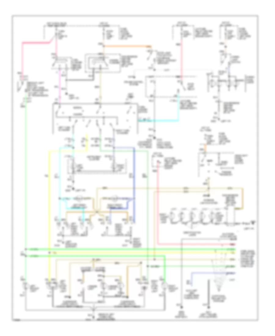
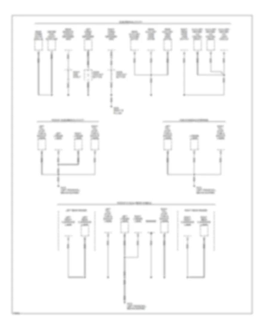
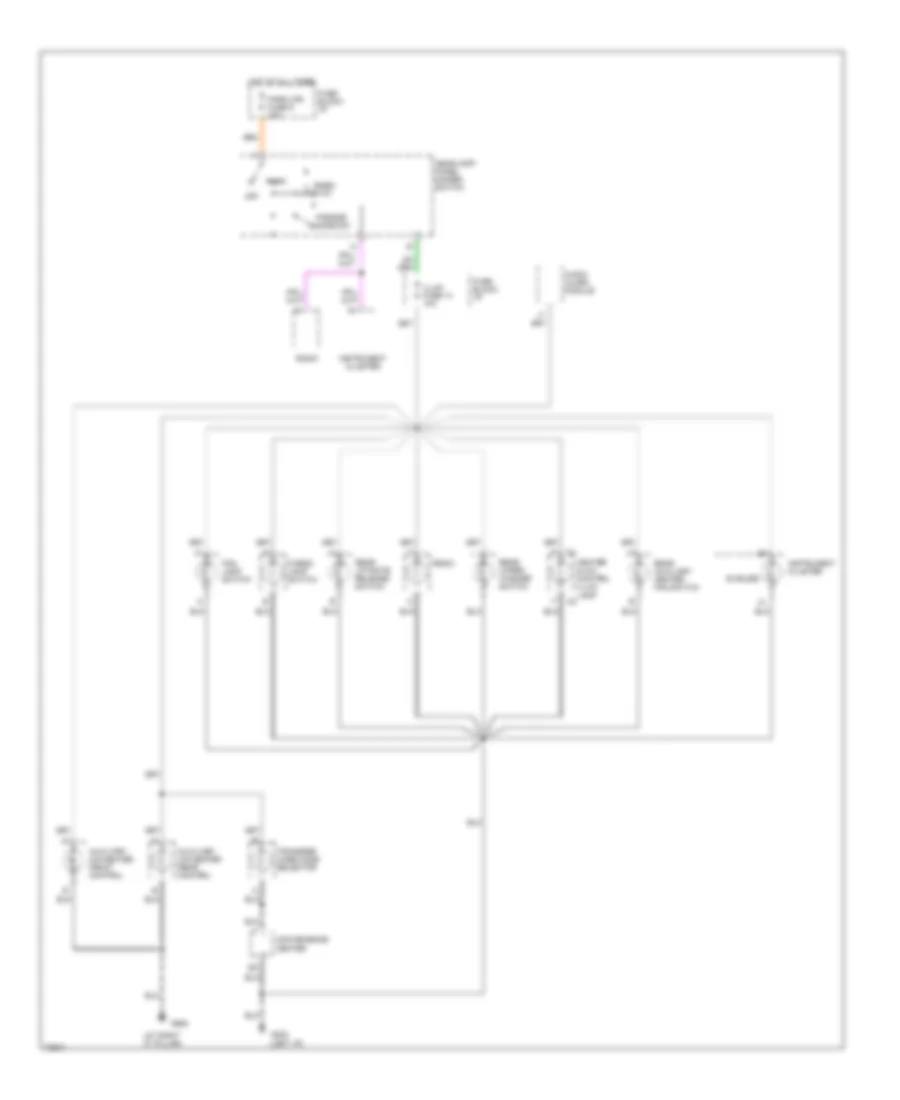
EXTERIOR LIGHTS
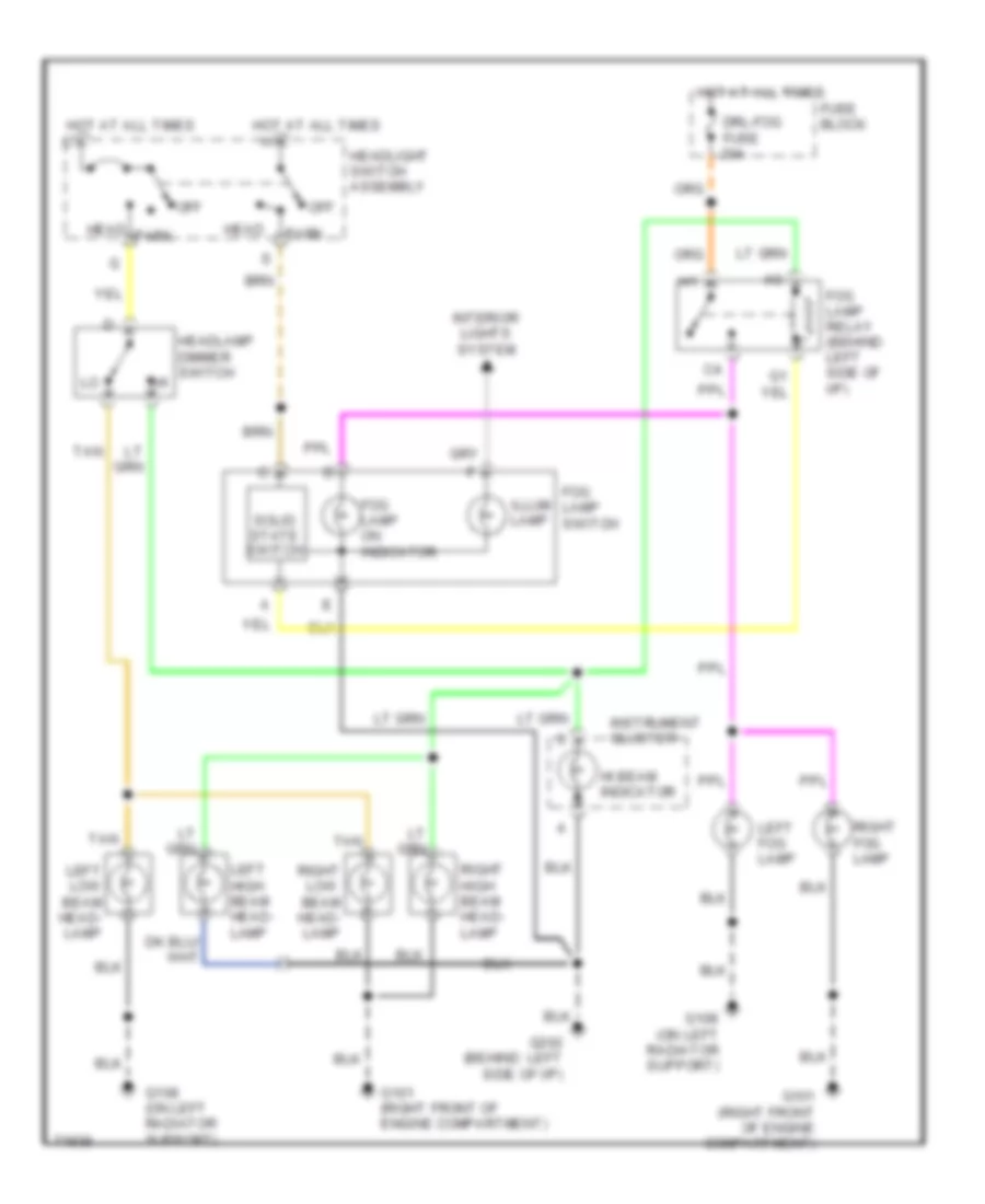
Exterior Light Wiring Diagram (1 of 2) for GMC Pickup K1995 2500
List of elements for Exterior Light Wiring Diagram (1 of 2) for GMC Pickup K1995 2500:
- (a/t)
- (behind center of i/p)
- (left i/p)
- (left radiator support)
- (m/t)
- (not used)
- (on brake pedal support bracket)
- (rear of left wheelwell, behind bumper)
- (right front engine compt)
- Ance lamp
- Auxiliary lead (taped near fuse block)
- Backup light switch (m/t-left side of transmission) (a/t-left top of transmission)
- Cargo
- Cargo lamp switch
- Cargo/ chmsl lamps
- Chmsl
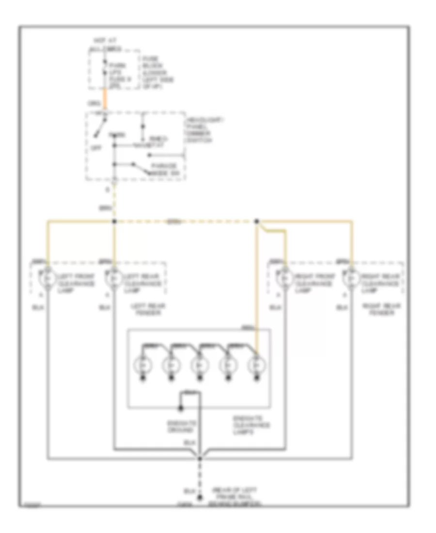
- Clear-
- Clearance lamps circuit (w/dual rear wheels)
- Convenience center (behind left side of i/p)
- Cruise control system
- Ctsy lps fuse 3 20a
- Fuse block (lower left side of i/p)
- G103 (vin h, k & z- right front wheelhouse)
- G107
- G108
- G120 (vin p-right top rear of cyl. head)
- G200
- G202 (left i/p)
- G404
- G411 (left trailer hitch support)
- G909 (on #1 roof bow)
- Hazard
- Hazard flasher
- Headlight/ panel dimmer switch
- Hot at all times
- Hot in run, bulb test or start
- Identification lamps
- Instrument cluster
- Interior lights system
- Left backup light
- Left clear- ance lamp
- Left front marker light
- Left front park/ turn lights
- Left tail/ stop/ turn light
- Left turn & hazard
- Left turn ind.
- License light
- License lights
- Maxi fuse 2 30a
- Normal
- Off
- Parade mode sw
- Park
- Park lps fuse 9 20a
- Platform hitch ground
- Pnk
- Red
- Rheo- stat
- Right
- Right backup light
- Right front marker light
- Right front park/ turn lights
- Right tail/ stop/ turn light
- Right turn & hazard
- Right turn ind.
- Stop lamp relay
- Stop lamp/ tcc switch
- Stop/ haz fuse 1 15a
- Turn flasher
- Turn- b/u fuse 16 15a
- Turn- hazard switch
- U/h fuse/ relay center (left rear engine compt)
- W/ step bumper
- W/o step bumper
- W/optional trailer tow package
- Wire leads are spliced to trailer wiring, or connected to trailer wire plug
Exterior Light Wiring Diagram (2 of 2) for GMC Pickup K1995 2500
List of elements for Exterior Light Wiring Diagram (2 of 2) for GMC Pickup K1995 2500:
- (rear of left frame rail, behind bumper)
- All times
- Endgate clearance lamps
- Endgate cround
- Fuse block (lower left side of i/p)
- G404
- Headlight/ panel dimmer switch
- Hot at
- Left front clearance lamp
- Left rear clearance lamp
- Left rear fender
- Off
- Parade mode sw
- Park
- Park lps fuse 9 20a
- Rheo- stat
- Right front clearance lamp
- Right rear clearance lamp
- Right rear fender
GROUND DISTRIBUTION
Ground Distribution Wiring Diagram (1 of 4) for GMC Pickup K1995 2500
List of elements for Ground Distribution Wiring Diagram (1 of 4) for GMC Pickup K1995 2500:
- A/c pressure switch
- A16
- All except 4.3l
- Ashtray lamp
- Auxiliary battery relay
- Auxiliary cooling fan
- Auxiliary power outlet
- Battery
- Body ground
- Btsi ground
- Cargo lamp switch (pickup)
- Cigarette lighter assembly
- Convenience center
- Daytime running lights module
- Drl relay
- Engine coolant level indicator module (diesel)
- Fog lamp switch
- From conven- ience center
- G100 (left inner fender, near battery)
- G101 (right inner fender, below underhood reel lamp)
- G108 (left radiator support, near left headlamp)
- G132 (on engine block)
- G202 (behind left side of i/p)
- Headlamp dimmer switch
- Heater/ a/c control switch
- Ignition switch ground
- Instrument cluster
- Instrument panel compartment box lamp
- Left fog lamp
- Left front door jamb switch
- Left front park/ turn lamp
- Left high beam headlamp
- Left high/ low beam headlamp
- Left horn
- Left low beam headlamp
- Left snow- plow lamp, turn signal relay
- Radio
- Rear auxiliary heater fan switch
- Rear window release switch
- Rear window washer pump
- Rear window wiper/ washer switch
- Right fog lamp
- Right front door jamb switch
- Right front park/ turn lamp
- Right high beam headlamp
- Right high/ low beam headlamp
- Right horn
- Right low beam headlamp
- Right snow- plow lamp, turn signal relay
- Steering column ground
- Turn signal flasher
- Uncoated
- W/ drl
- W/o drl
- With v22 appearance package
Ground Distribution Wiring Diagram (2 of 4) for GMC Pickup K1995 2500
List of elements for Ground Distribution Wiring Diagram (2 of 4) for GMC Pickup K1995 2500:
- 4-wheel drive indicator
- 5.0l & 5.7l w/ m/t
- 5.7l w/ h/d a/t only
- A/c compressor clutch
- A/c low pressure switch
- A12
- Abs module
- All gasoline w/ a/t and 4.3l & 7.4l w/ m/t
- Back-up lamp switch
- Blower motor
- Blower motor relay
- Brake pressure warning switch
- Cruise control module
- Data link connector
- Egr electronic vacuum regulator solenoid
- Electronic spark control module
- Fuel heater
- Fuel pump
- Fuel pump cycle module
- Fuel pump relay
- G110 (left front of engine near thermostat housing)
- G117 (right top rear of cylinder head)
- G120 (right top of cylinder head)
- G131 (on intake manifold)
- Glow plug relay
- Heated oxygen sensor
- Low coolant level sensor
- Powertrain control unit
- Tan
- Under- hood reel lamp
- Underhood fuse/ relay center
- Vehicle speed sensor buffer
- Water in fuel sensor
- Windshield washer motor
- Windshield wiper motor
- With diesel engine only
Ground Distribution Wiring Diagram (3 of 4) for GMC Pickup K1995 2500
List of elements for Ground Distribution Wiring Diagram (3 of 4) for GMC Pickup K1995 2500:
- 4wd indicator
- Amplifier relay
- C210
- C220
- Center high mount stop- lamp
- Convenience center
- Data link connector
- Diesel engines
- Door lock relay
- Fuel pump
- Fuel pump relay
- G120 (right top of cylinder head)
- Left front power window/ lock switch
- Left rear power window switch
- Left side clearance lamp
- Power amplifier
- Power mirror switch
- Power seat
- Powertrain control unit
- Rear window lockout switch
- Remote keyless entry module
- Right front power window switch
- Right rear power window switch
- Right side clearance lamp
- Roof marker lamps
- Seat belt switch
- To g202
- Transfer case mode selector illumination
- Vehicle speed sensor buffer
Ground Distribution Wiring Diagram (4 of 4) for GMC Pickup K1995 2500
List of elements for Ground Distribution Wiring Diagram (4 of 4) for GMC Pickup K1995 2500:
- Auxiliary heater/ a/c control front
- Auxiliary heater/ a/c control rear
- Auxiliary heater/ a/c logic module
- Cab chassis & stepside
- Center high mount stoplamp
- Door contact button
- Endgate
- G305 (right 'b' pillar)
- G415 (left frame rail, behind bumper)
- Left cargo door defogger grid
- Left front clearance lamp
- Left license lamp
- Left rear clearance lamp
- Left rear fender
- Left tail, stop, turn & backup lamps
- License lamp
- Pickup w/ dual rear wheels
- Pickup, suburban & utility
- Rear auxiliary blower motor
- Rear auxiliary mode door motor
- Rear auxiliary temp door motor
- Rear endgate window defogger grid
- Rear wiper motor module
- Right cargo door defogger grid
- Right front clearance lamp
- Right gas strut
- Right license lamp
- Right rear clearance lamp
- Right rear door jamb switch
- Right rear fender
- Right tail, stop, turn & backup lamps
- Suburban & utility
HEADLIGHTS
Fog Lamp Wiring Diagram, Composite with DRL for GMC Pickup K1995 2500
List of elements for Fog Lamp Wiring Diagram, Composite with DRL for GMC Pickup K1995 2500:
- (at park brake, under left side of i/p)
- Bulb check
- Convenience center
- Daytime running lamp indicator
- Daytime running lamps module (behind left side of i/p)
- Daytime running lamps relay (engine compartment front plenum panel)
- Diode
- Drl-fog fuse 15 20a
- Fog lamp on indicator
- Fog lamp relay
- Fog lamp switch
- Fog lts enable
- Fuse block
- G101 (right front of engine compartment)
- G108 (on left radiator support)
- G119 (right front of engine compartment)
- G202 (behind left side of i/p)
- Gauges fuse 4 10a
- Ground
- Head
- Headlamp dimmer switch
- Headlight switch assembly
- Hi beam feed
- Hi beam indicator
- Hot at all times
- Hot in run, bulb test or start
- Ignition
- Illum lamp
- Instrument cluster
- Interior lights system
- Lamp feed
- Left fog lamp
- Left high beam headlamp
- Left low beam headlamp
- Off
- Output to relay
- Park
- Park brake warning switch
- Pickup ext. cab
- Pnk
- Right fog lamp
- Right high beam headlamp
- Right low beam headlamp
- Solid state switch
- Suburban utility crew cab
- Tan
Fog Lamp Wiring Diagram, Sealed Beam with DRL for GMC Pickup K1995 2500
List of elements for Fog Lamp Wiring Diagram, Sealed Beam with DRL for GMC Pickup K1995 2500:
- (at park brake, under left side of i/p)
- Bulb check
- Convenience center
- Daytime running lamp indicator
- Daytime running lamps module (behind left side of i/p)
- Daytime running lamps relay (engine compartment front plenum panel)
- Diode
- Drl-fog fuse 15 20a
- Fog lamp on indicator
- Fog lamp relay
- Fog lamp switch
- Fog lts enable
- Fuse block
- G101 (right front of engine compartment)
- G101 (right front wheelhouse)
- G108 (on left radiator support)
- G202 (behind left side of i/p)
- Gauges fuse 4 10a
- Ground
- Head
- Headlamp dimmer switch
- Headlight switch assembly
- Hi beam feed
- Hi beam indicator
- Hot at all times
- Hot in run, bulb test or start
- Ignition
- Illum lamp
- Instrument cluster
- Interior lights system
- Lamp feed
- Left fog lamp
- Left headlamp assembly
- Off
- Output to relay
- Park
- Park brake warning switch
- Pickup ext. cab
- Pnk
- Right fog lamp
- Right headlamp assembly
- Solid state switch
- Suburban utility crew cab
- Tan
Headlight Wiring Diagram, Composite with DRL for GMC Pickup K1995 2500
List of elements for Headlight Wiring Diagram, Composite with DRL for GMC Pickup K1995 2500:
- (at park brake, under left side of i/p)
- Bulb check
- Daytime running lamp indicator
- Daytime running lamps module (behind left side of i/p)
- Daytime running lamps relay (engine compartment front plenum panel)
- Drl-fog fuse 15 20a
- Fuse block
- G101 (right front of engine compartment)
- G108 (on left radiator support)
- G202 (behind left side of i/p)
- Gauges fuse 4 10a
- Ground
- Head
- Headlamp dimmer switch
- Headlight switch assembly
- Hi beam feed
- Hi beam indicator
- Hot at all times
- Hot in run, bulb test or start
- Ignition
- Instrument cluster
- Lamp feed
- Left high beam headlamp
- Left low beam headlamp
- Off
- Output to relay
- Park
- Park brake warning switch
- Pnk
- Right high beam headlamp
- Right low beam headlamp
- Tan
Headlight Wiring Diagram, Composite without DRL for GMC Pickup K1995 2500
List of elements for Headlight Wiring Diagram, Composite without DRL for GMC Pickup K1995 2500:
- Drl-fog fuse 20a
- Fog lamp on indicator
- Fog lamp relay (behind left side of i/p)
- Fog lamp switch
- Fuse block
- G101 (right front of engine compartment)
- G108 (on left radiator support)
- G202 (behind left side of i/p)
- Head
- Headlamp dimmer switch
- Headlight switch assembly
- Hi beam indicator
- Hot at all times
- Illum lamp
- Instrument cluster
- Interior lights system
- Left fog lamp
- Left high beam head- lamp
- Left low beam head- lamp
- Off
- Park
- Right fog lamp
- Right high beam head- lamp
- Right low beam head- lamp
- Solid state switch
- Tan
Headlight Wiring Diagram, Sealed Beam with DRL for GMC Pickup K1995 2500
List of elements for Headlight Wiring Diagram, Sealed Beam with DRL for GMC Pickup K1995 2500:
- (at park brake, under left side of i/p)
- Bulb check
- Daytime running lamp indicator
- Daytime running lamps module (behind left side of i/p)
- Daytime running lamps relay (engine compartment front plenum panel)
- Drl-fog fuse 20a
- Fuse block
- G101 (right front wheelhouse)
- G202 (behind left side of i/p)
- Gauges fuse 4 10a
- Ground
- Head
- Headlamp dimmer switch
- Headlight switch assembly
- Hi beam feed
- Hi beam indicator
- Hot at all times
- Hot in run, bulb test or start
- Ignition
- Instrument cluster
- Lamp feed
- Left headlamp assembly
- Off
- Output to relay
- Park
- Park brake warning switch
- Pnk
- Right headlamp assembly
- Tan
Headlight Wiring Diagram, Sealed Beam without DRL for GMC Pickup K1995 2500
List of elements for Headlight Wiring Diagram, Sealed Beam without DRL for GMC Pickup K1995 2500:
- Drl-fog fuse 20a
- Fog lamp on indicator
- Fog lamp relay (behind left side of i/p)
- Fog lamp switch
- Fuse block
- G101 (right front of engine compartment)
- G101 (right front wheelhouse)
- G108 (on left radiator support)
- G202 (behind left side of i/p)
- Head
- Headlamp dimmer switch
- Headlight switch assembly
- Hi beam indicator
- Hot at all times
- Illum lamp
- Instrument cluster
- Interior lights system
- Left fog lamp
- Left headlamp assembly
- Off
- Park
- Right fog lamp
- Right headlamp assembly
- Solid state switch
- Tan
HORN
Horn Wiring Diagram for GMC Pickup K1995 2500
List of elements for Horn Wiring Diagram for GMC Pickup K1995 2500:
- (on sheet metal,
- (right inner
- (w/ front end appearance package)
- Convenience center (under left side of i/p)
- G100 above left headlamp)
- G101 fender, near battery)
- Horn mini fuse 20a
- Horn relay
- Horn switch
- Hot at all times
- Left horn (at front of vehicle)
- Right horn (at front of vehicle)
- Steering wheel
- Underhood fuse/relay center
INSTRUMENT CLUSTER
Instrument Cluster Wiring Diagram, Diesel for GMC Pickup K1995 2500
List of elements for Instrument Cluster Wiring Diagram, Diesel for GMC Pickup K1995 2500:
- A/t
- Accy
- Air bag
- Anti- lock brakes
- Anti-lock brakes system
- Brake
- Brake pressure modulator valve (left wheelhouse)
- Brake pressure warning switch (on rear of brake pressure modulator valve body)
- Bulb test
- Check gauges
- Check gauges lamp driver
- Convenience center (behind left side of i/p)
- Daytime running lamps
- Electronic prndl display module
- Eng-i mini fuse 20a
- Engine controls system
- Engine coolant temperature sender (front of left cylinder head)
- Exterior lights system
- Fuel gauge
- Fuel pump & sender (in fuel tank)
- G117 (top rear of right side cylinder head)
- G117 (top right rear of engine)
- G202 (behind left side of i/p)
- Gauges fuse 4 10a
- Gen
- Headlights system
- Headlights system (drl)
- Hi beam
- Hot in run or start
- I/p fuse block (behind left side of i/p)
- Ignition switch
- Illum
- Instrument cluster
- Interior lights system
- Left turn
- Lock
- Low coolant
- Low coolant level sender (in coolant reservoir)
- Low engine coolant level indicator module (under center of i/p)
- M/t
- Nca
- Off
- Oil press
- Oil pressure switch/sender (left rear top of engine)
- Park brake warning switch (left end of i/p)
- Pnk
- Range
- Right turn
- Run
- Safety belt
- Selector
- Service engine soon
- Service throttle soon
- Sound systems
- Speed- ometer
- Start
- Starting/charging system
- Tach
- Tan
- Temp gauge
- Trans fuse 20 10a
- Transmisssion
- Trunk/ tailgate/ fuel doors system
- Trunk/tail- gate/fuel doors system
- Underhood fuse/relay center (left rear of engine comp't)
- Up- shift
- Vehicle speed sensor (left rear of transmission)
- Vehicle speed sensor buffer (behind right end of i/p)
- Volt- meter
- W/ drl only
- W/o drl only
- Wait to start
- Warning systems
- Water in fuel
- Water-in fuel sensor (top rear of engine)
Instrument Cluster Wiring Diagram, Gasoline for GMC Pickup K1995 2500
List of elements for Instrument Cluster Wiring Diagram, Gasoline for GMC Pickup K1995 2500:
- system
- (left side of
- A/t
- Accy
- Air bag
- Anti- lock brakes
- Anti-lock brakes system
- Brake
- Brake pressure modulator valve (left wheelhouse)
- Brake pressure warning switch (on rear of brake pressure modulator valve body)
- Bulb test
- Check gauges
- Check gauges lamp driver
- Convenience center (behind left side of i/p)
- Daytime running lamps
- Electronic prndl display module
- Engine controls system
- Engine coolant temperature sender (front of left cylinder head)
- Exterior lights system
- Fuel gauge
- Fuel pump & sender (in fuel tank)
- Fuel pump oil pressure switch/sender (top rear of engine)
- G103 (right front wheelhouse)
- G117 (rear of right cyl head)
- G134 (top front center of engine)
- G202 (behind left side of i/p)
- Gauges fuse 4 10a
- Gen
- Headlights system
- Headlights system (drl)
- Hi beam
- Hot in run or start
- I/p fuse block (behind left side of i/p)
- Ignition switch
- Illum
- Instrument cluster
- Interior lights system
- Left turn
- Lock
- M/t
- Nca
- Off
- Oil press
- Park brake warning switch (left end of i/p)
- Pnk
- Range selector
- Right turn
- Run
- Safety belt
- Service engine soon
- Sound systems
- Speed- ometer
- Start
- Starting/charging system
- Tach
- Tan
- Temp gauge
- Trans fuse 20 10a
- Transmission
- Transmission)
- Trunk/ tailgate/ fuel doors system
- Trunk/tail- gate/fuel doors system
- Up- shift
- Vehicle speed sensor (left rear of transmission)
- Vehicle speed sensor buffer (behind right end of i/p)
- Volt- meter
- W/ drl only
- W/o drl only
- Warning systems
INTERIOR LIGHTS
Courtesy Lamps Wiring Diagram, without Auxiliary Lighting for GMC Pickup K1995 2500
List of elements for Courtesy Lamps Wiring Diagram, without Auxiliary Lighting for GMC Pickup K1995 2500:
- (right top rear
- Cargo door jamb switch
- Courtesy
- Ctsy fuse 3 20a
- Dome lamp defeat
- Front dome lamp
- Fuse block: i/p
- G202 (left i/p)
- G905 (right "c" pillar)
- Headlamp & panel dimmer switch
- Horn mini fuse 20a
- Hot at all times
- I/p compt box lamp
- Left
- Left front door jamb switch
- Left i/p courtesy lamp
- Of cylinder head)
- Rear dome lamp
- Rear door jamb switch
- Right
- Right front door jamb switch
- Right i/p courtesy lamp
- Suburban only
- Tahoe, yukon & suburban only
- Underhood fuse/relay center
- Underhood lamp
- Underhood reel lamp
- Vin p-g117
- Vin z, h & k-g103 (right front wheelhouse)
Instrument Illumination Wiring Diagram (1 of 2) for GMC Pickup K1995 2500
List of elements for Instrument Illumination Wiring Diagram (1 of 2) for GMC Pickup K1995 2500:
- (6) bulbs
- (at right "c" pillar)
- (left i/p)
- Audio alarm module
- Auxiliary a/c-heater front control
- Auxiliary a/c-heater rear control
- Cargo lamp switch
- Convenience center
- Fog lamp switch
- Fuse block: i/p
- G202
- G905
- Headlamp/ panel dimmer switch
- Heater & a/c control illum.
- Hot at all times
- Illum fuse 14 10a
- Instrument cluster
- Lamp c2
- Off
- Parade mode sw
- Park
- Park lps fuse 9 20a
- Radio
- Rear auxiliary heater fan switch
- Rear liftgate release switch
- Rear wiper/ washer switch
- Rheo- stat
- Transfer case mode selector
Instrument Illumination Wiring Diagram (2 of 2) for GMC Pickup K1995 2500
List of elements for Instrument Illumination Wiring Diagram (2 of 2) for GMC Pickup K1995 2500:
- (left i/p)
- Ash tray lamp
- Convenience center
- Fuse block: i/p
- G202
- Headlamp/ panel dimmer switch
- Hot at all times
- Left front power mirror switch
- Left rear power window switch
- Off
- Parade mode sw
- Park
- Park lps fuse 9 20a
- Rear window lockout switch
- Remote outside rearview mirror switch
- Rheo- stat
- Right front power window switch
- Right rear power window switch
POWER DISTRIBUTION
Power Distribution Wiring Diagram, Diesel (1 of 6) for GMC Pickup K1995 2500
List of elements for Power Distribution Wiring Diagram, Diesel (1 of 6) for GMC Pickup K1995 2500:
- A/t
- Acc
- Aux fan mini fuse 30a
- Auxiliary cooling fan relay
- B10
- Brake lamp relay
- Brake pressure modulator valve
- Clutch start switch
- Crank fuse 8 10a
- Diagnostic energy reserve module
- Fuel pump relay
- Fusible
- Generator
- Heater & a/c control
- I/p fuse block
- Ignition switch
- Instrument cluster
- Left battery
- Link
- Lock
- M/t
- Maxi fuse 2 30a
- Maxi fuse 30a
- Maxi fuse 4 60a
- Maxi fuse 5 50a
- Maxi fuse 6 40a
- Maxi fuse 7 50a
- Maxi fuse 8 50a
- Nca
- Off
- Pnk
- Red
- Remote battery stud
- Right battery
- Rr defog mini fuse 30a
- Run
- Start
- Starter motor solenoid
- Stud 'a'
- Stud 'b'
- To blower relays
- To ctsy, pk lps, drl/fog fuses & head- lamp switch
- To ecm-b, horn & a/c comp fuses
- To gauges, air bag fuses
- To htr-a/c, brake, 4wd & cruise fuses
- To ign-e, ecm-i & eng-1 fuses
- To radio/ batt, cig ltr, aux pwr fuses & pwr accy breaker
- To wiper, radio & rear wiper fuses
- Trans fuse 20 10a
- Trans- mission
- Transmission range switch
- Underhood fuse/ relay center
Power Distribution Wiring Diagram, Diesel (2 of 6) for GMC Pickup K1995 2500
List of elements for Power Distribution Wiring Diagram, Diesel (2 of 6) for GMC Pickup K1995 2500:
- A/c comp mini fuse 10a
- A/c low pressure cutout switch
- Auxiliary cooling fan relay
- C205
- Convenience center
- Ecm-b mini fuse 20a
- Ecm-i mini fuse 20a
- Egr boost pulse width modulation solenoid
- Egr solenoid valve
- Electronic injection pump
- Eng-i mini fuse 20a
- From aux fan fuse
- From ignition switch
- From maxi fuse 6
- Fuel heater
- Fuel pump oil pressure switch/ sender
- Fuel pump relay
- Fuel sol mini fuse 20a
- Glow plug relay
- High blower relay
- Horn mini fuse 20a
- Horn relay
- I/p fuse block
- Ign-e mini fuse 10a
- Linear egr pulse width modulation solenoid
- Low blower relay
- Maxi fuse 3 50a
- Medium blower relay
- Pnk
- Powertrain control module (pcm)
- Radio
- Radio fuse 10a
- Rear wiper fuse 23 25a
- Rear wiper/ washer switch
- Red
- Suburban & utility only
- Suburban only
- To power window circuit breaker
- Under- hood fuse/ relay center
- Underhood fuse/ relay center
- Underhood reel lamp
- Water in fuel sensor
- Wiper fuse 25a
- Wiper motor module
- Wiper/ washer switch
Power Distribution Wiring Diagram, Diesel (3 of 6) for GMC Pickup K1995 2500
List of elements for Power Distribution Wiring Diagram, Diesel (3 of 6) for GMC Pickup K1995 2500:
- All except pickup & 2 door utility w/o keyless entry
- All except pickup & 2-door utility w/o keyless entry
- All other
- Amplifier relay
- Audio alarm module (convenience center)
- Aux pwr fuse 7 25a
- Auxiliary power feed
- Buckets or split bench only
- C210
- Cig ltr fuse 13 20a
- Cigarette lighter
- Convenience center
- Door lock relay
- From maxi fuse 7
- G202 (behind left side of i/p)
- Hazard flasher (convenience center)
- I/p fuse block
- Left front door lock switch
- Left front power lumbar switch
- Left front power seat
- Pickup/2 door utility w/o keyless entry
- Power accy circuit breaker 30a
- Radio
- Radio batt fuse 19 10a
- Rear liftgate release switch
- Red
- Remote keyless entry module
- Right front door lock switch
- Right front power lumbar switch
- Stop/ hazard fuse 1 20a
- Suburban & utility only
- Tcc/ stoplamp switch
Power Distribution Wiring Diagram, Diesel (4 of 6) for GMC Pickup K1995 2500
List of elements for Power Distribution Wiring Diagram, Diesel (4 of 6) for GMC Pickup K1995 2500:
- Audio alarm module
- Auxiliary heater/ a/c control front
- Auxiliary heater/ a/c control rear
- C219
- Cargo lamp switch
- Convenience center
- Ctsy fuse 20a
- Daytime running lamps relay
- Diode d200
- Drl/fog fuse 15 20a
- Fog lamp relay
- Fog lamp switch
- From maxi fuse 8
- Front dome/ reading lamps
- Glove box lamp
- Headlamp and panel dimmer switch
- Heater/ a/c control lamp
- I/p fuse block
- Illum fuse 10a
- Instrument cluster
- Left front door courtesy lamp
- Left i/p courtesy lamp
- Left rear door courtesy lamp
- Left vanity mirror
- Park lamps
- Pickup
- Pickup only
- Pk lps fuse 20a
- Radio
- Rear dome/ reading lamps
- Rear liftgate release switch
- Rear wiper/ washer switch
- Red
- Remote outside mirror switch
- Right front door courtesy lamp
- Right i/p courtesy lamp
- Right rear door courtesy lamp
- Right vanity mirror
- Spare power source
- Suburban & utility
- Suburban & utility only
- Suburban only
- Two wheel drive indicator
Power Distribution Wiring Diagram, Diesel (5 of 6) for GMC Pickup K1995 2500
List of elements for Power Distribution Wiring Diagram, Diesel (5 of 6) for GMC Pickup K1995 2500:
- 4wd fuse 24 25a
- Abs brake module
- All others
- Auxiliary heater/ a/c control logic module
- Auxiliary heater/ a/c control module (front)
- Auxiliary heater/ a/c control module (rear)
- Auxiliary storage battery relay
- Brake fuse 18 10a
- C205
- Convenience center
- Cruise control switch
- Cruise fuse 6 10a
- Four wheel drive indicator
- From ignition switch
- Heater/ a/c control
- High blower relay (rear)
- Htr-a/c fuse 12 25a
- I/p fuse block
- Low blower relay (rear)
- Medium blower relay (rear)
- Mode door motor
- Rear auxiliary mode door motor
- Rear auxiliary temperature door motor
- Recirc- ulation door motor
- Rr hvac fuse 5 (suburban only) 10a
- Spare power source
- Suburban & diesel
- Tcc/ stoplamp switch
- Temper- ature door motor
Power Distribution Wiring Diagram, Diesel (6 of 6) for GMC Pickup K1995 2500
List of elements for Power Distribution Wiring Diagram, Diesel (6 of 6) for GMC Pickup K1995 2500:
- A10
- Air bag fuse 10 10a
- Arming sensor
- Audio alarm module
- Backup lamp switch
- C210
- C218
- Convenience center
- Crewcab, suburban & utility only
- Daytime running lamps module
- Daytime running lamps relay
- Diagnostic energy reserve module
- Electro- chromic mirror
- From ignition switch
- From rear wiper fuse
- Gauges fuse 4 10a
- Head- lamp/ panel dimmer switch
- I/p fuse block
- Instrument cluster
- Left front power window switch
- Low engine coolant level module
- M/t only
- Pnk
- Pwr wdo circuit brkr 30a
- Rear window lockout switch
- Remote keyless entry module
- Right front power window switch
- Turn b/u fuse 16 20a
- Turn signal lamp flasher
- Vehicle speed sensor buffer module
Power Distribution Wiring Diagram, Gasoline (1 of 6) for GMC Pickup K1995 2500
List of elements for Power Distribution Wiring Diagram, Gasoline (1 of 6) for GMC Pickup K1995 2500:
- A/t
- Acc
- Aux fan mini fuse 30a
- Auxiliary cooling fan relay
- B10
- Battery
- Brake lamp relay
- Brake pressure modulator valve
- Clutch start switch
- Crank fuse 8 10a
- Diagnostic energy reserve module
- Except 4.3l
- Fusible
- Generator
- Heater & a/c control
- I/p fuse block
- Ignition switch
- Instrument cluster
- Link
- Lock
- M/t
- M/t only
- Maxi fuse 2 30a
- Maxi fuse 30a
- Maxi fuse 4 60a
- Maxi fuse 5 50a
- Maxi fuse 6 40a
- Maxi fuse 7 50a
- Maxi fuse 8 50a
- Nca
- Off
- Pnk
- Powertrain control module (pcm)
- Red
- Remote battery stud
- Rr defog mini fuse 30a
- Run
- Start
- Starter motor solenoid
- Stud 'a'
- Stud 'b'
- To blower relays
- To ctsy, pk lps, drl/fog fuses & head- lamp switch
- To ecm-b, horn & a/c comp fuses
- To gauges, air bag fuses
- To htr-a/c, brake, 4wd & cruise fuses
- To ign-e, ecm-i & eng-1 fuses
- To radio/ batt, cig ltr, aux pwr fuses & pwr accy breaker
- To wiper, radio & rear wiper fuses
- Trans fuse 20 10a
- Trans- mission
- Transmission range switch
- Underhood fuse/ relay center
Power Distribution Wiring Diagram, Gasoline (2 of 6) for GMC Pickup K1995 2500
List of elements for Power Distribution Wiring Diagram, Gasoline (2 of 6) for GMC Pickup K1995 2500:
- 4.3l, 5.0l & 5.7l only
- 5.7l h/d w/ m/t
- 5.7l w/ h/d a/t
- A/c comp mini fuse 10a
- A/c low pressure cutout switch
- Auxiliary cooling fan relay
- C205
- Convenience center
- E15
- E16
- Ecm-b mini fuse 20a
- Ecm-i mini fuse 20a
- Egr electronic vacuum regulator solenoid
- Egr solenoid valve
- Electronic spark control module
- Eng-i mini fuse 20a
- Evaporative emissions canister purge solenoid
- Except 4.3l
- F15
- From aux fan fuse
- From ignition switch
- From maxi fuse 6
- Fuel cycle control module
- Fuel injector 1
- Fuel injector 2
- Fuel pump oil pressure switch/ sender
- Fuel pump relay
- Heated oxygen sensor
- High blower relay
- Horn mini fuse 20a
- Horn relay
- I/p fuse block
- Ign-e mini fuse 10a
- Linear egr solenoid
- Low blower relay
- M/t only
- Maxi fuse 3 50a
- Medium blower relay
- Pnk
- Powertrain control module
- Powertrain control module (pcm)
- Radio
- Radio fuse 10a
- Rear wiper fuse 23 25a
- Rear wiper/ washer switch
- Red
- Suburban & utility only
- Suburban only
- To power window circuit breaker
- Under- hood fuse/ relay center
- Underhood fuse/ relay center
- Underhood reel lamp
- Wiper fuse 25a
- Wiper motor module
- Wiper/ washer switch
Power Distribution Wiring Diagram, Gasoline (3 of 6) for GMC Pickup K1995 2500
List of elements for Power Distribution Wiring Diagram, Gasoline (3 of 6) for GMC Pickup K1995 2500:
- All except pickup & 2 door utility w/o keyless entry
- All except pickup & 2-door utility w/o keyless entry
- All other
- Amplifier relay
- Audio alarm module (convenience center)
- Aux pwr fuse 7 25a
- Auxiliary power feed
- Buckets or split bench only
- C210
- Cig ltr fuse 13 20a
- Cigarette lighter
- Convenience center
- Door lock relay
- From maxi fuse 7
- G202 (behind left side of i/p)
- Hazard flasher (convenience center)
- I/p fuse block
- Left front door lock switch
- Left front power lumbar switch
- Left front power seat
- Pickup only
- Pickup/2 door utility w/o keyless entry
- Power accy circuit breaker 30a
- Radio
- Radio batt fuse 19 10a
- Rear liftgate release switch
- Red
- Remote keyless entry module
- Right front door lock switch
- Right front power lumbar switch
- Stop/ hazard fuse 1 20a
- Suburban & utility only
- Tcc/ stoplamp switch
Power Distribution Wiring Diagram, Gasoline (4 of 6) for GMC Pickup K1995 2500
List of elements for Power Distribution Wiring Diagram, Gasoline (4 of 6) for GMC Pickup K1995 2500:
- Audio alarm module
- Auxiliary heater/ a/c control front
- Auxiliary heater/ a/c control rear
- C219
- Cargo lamp switch
- Convenience center
- Ctsy fuse 20a
- Daytime running lamps relay
- Diode d200
- Drl/fog fuse 15 20a
- Fog lamp relay
- Fog lamp switch
- From maxi fuse 8
- Front dome/ reading lamps
- Glove box lamp
- Headlamp and panel dimmer switch
- Heater/ a/c control lamp
- I/p fuse block
- Illum fuse 10a
- Instrument cluster
- Left front door courtesy lamp
- Left i/p courtesy lamp
- Left rear door courtesy lamp
- Left vanity mirror
- Park lamps
- Pickup
- Pickup only
- Pk lps fuse 20a
- Radio
- Rear dome/ reading lamps
- Rear liftgate release switch
- Rear wiper/ washer switch
- Red
- Remote outside mirror switch
- Right front door courtesy lamp
- Right i/p courtesy lamp
- Right rear door courtesy lamp
- Right vanity mirror
- Spare power source
- Suburban & utility
- Suburban & utility only
- Suburban only
- Two wheel drive indicator
Power Distribution Wiring Diagram, Gasoline (5 of 6) for GMC Pickup K1995 2500
List of elements for Power Distribution Wiring Diagram, Gasoline (5 of 6) for GMC Pickup K1995 2500:
- 4wd fuse 24 25a
- Abs brake module
- All others
- Auxiliary heater/ a/c control logic module
- Auxiliary heater/ a/c control module (front)
- Auxiliary heater/ a/c control module (rear)
- Auxiliary storage battery relay
- Brake fuse 18 10a
- C205
- Convenience center
- Cruise control module
- Cruise control switch
- Cruise fuse 6 10a
- Four wheel drive indicator
- From ignition switch
- Gasoline only
- Heater/ a/c control
- High blower relay (rear)
- Htr-a/c fuse 12 25a
- I/p fuse block
- Low blower relay (rear)
- Medium blower relay (rear)
- Mode door motor
- Rear auxiliary mode door motor
- Rear auxiliary temperature door motor
- Recirc- ulation door motor
- Rr hvac fuse 5 (suburban only) 10a
- Spare power source
- Suburban & diesel
- Tcc/ stoplamp switch
- Temper- ature door motor
Power Distribution Wiring Diagram, Gasoline (6 of 6) for GMC Pickup K1995 2500
List of elements for Power Distribution Wiring Diagram, Gasoline (6 of 6) for GMC Pickup K1995 2500:
- A10
- Air bag fuse 10 10a
- Arming sensor
- Audio alarm module
- Backup lamp switch
- C210
- C218
- Convenience center
- Crewcab, suburban & utility only
- Daytime running lamps module
- Daytime running lamps relay
- Diagnostic energy reserve module
- Electro- chromic mirror
- From ignition switch
- From rear wiper fuse
- Gauges fuse 4 10a
- Head- lamp/ panel dimmer switch
- I/p fuse block
- Instrument cluster
- Left front power window switch
- M/t only
- Pnk
- Pwr wdo circuit brkr 30a
- Rear window lockout switch
- Remote keyless entry module
- Right front power window switch
- Turn b/u fuse 16 20a
- Turn signal lamp flasher
- Vehicle speed sensor buffer module
POWER DOOR LOCKS
Door Lock Wiring Diagram, 2 Door for GMC Pickup K1995 2500
List of elements for Door Lock Wiring Diagram, 2 Door for GMC Pickup K1995 2500:
- Convenience center (under left side of i/p)
- Fuse block (lower left side of i/p)
- G202 (below left side of i/p)
- Hot at all times
- Left front door lock actuator
- Left front door lock switch
- Lock
- Pwr acc circuit breaker 20a
- Right front door lock actuator
- Right front door lock switch
- Solid state
- Tan
- Unlock
Door Lock Wiring Diagram, 4 Door for GMC Pickup K1995 2500
List of elements for Door Lock Wiring Diagram, 4 Door for GMC Pickup K1995 2500:
- Cig ltr fuse 13 20a
- Circuit breaker a 30a
- Convenience center (under left side of i/p)
- Door lock relay (under i/p, right side of brake pedal bracket)
- Fuse block (lower left side of i/p)
- G202 (left side of i/p)
- Hot at all times
- Left front door lock motor
- Left front door lock switch
- Left rear door lock motor
- Lock
- Lock relay
- Right front door lock motor
- Right front door lock switch
- Right rear door lock motor
- Solid state
- Tan
- Unlock
- Unlock relay
Keyless Entry Wiring Diagram, 2 Door for GMC Pickup K1995 2500
List of elements for Keyless Entry Wiring Diagram, 2 Door for GMC Pickup K1995 2500:
- Battery
- Cig ltr fuse 14 20a
- Convenience center
- Data link connector (under left side of i/p)
- Door lock relay (under center portion of i/p, near rke module)
- Fuse block (lower left side of i/p)
- G200 (behind left side of i/p)
- Gauges fuse 4 10a
- Ground
- Hot at all times
- Hot in run, bulb test or start
- Ignition
- Int lts input
- Interior lights system
- Keyless entry module (behind center of i/p)
- L fnt dr unlk output
- Left front door lock motor
- Left front door lock switch
- Liftgate release motor
- Liftgate/cargo rel
- Lock
- Lock doors output
- Pnk
- Program enable
- Pwr accy circuit breaker a 30a
- Rear cargo door lock motor (utility only)
- Right front door lock motor
- Right front door lock switch
- Tan
- Unlk doors output
- Unlock
- Utility w/ cargo doors
- Utility w/ liftgate
Keyless Entry Wiring Diagram, 4 Door for GMC Pickup K1995 2500
List of elements for Keyless Entry Wiring Diagram, 4 Door for GMC Pickup K1995 2500:
- Battery
- Cig ltr fuse 14 20a
- Convenience center
- Data link connector
- Door lock relay (under center portion of i/p, near rke module)
- Fuse block (lower left side of i/p)
- G200 (behind left side of i/p)
- Gauges fuse 4 10a
- Ground
- Hot at all times
- Hot in run, bulb test or start
- Ignition
- Interior lights system
- Jamb switch input
- Keyless entry module (behind center of i/p)
- L fnt dr unlk out
- Left front door lock motor
- Left front door lock switch
- Left rear door lock motor
- Liftgate release out
- Lock
- Lock doors out
- Pnk
- Program enable input
- Pwr accy circuit breaker a 30a
- Right front door lock motor
- Right front door lock switch
- Right rear door lock motor
- Tan
- Trunk, tailgate, fuel doors system
- Unlk doors out
- Unlock
POWER MIRRORS
Power Mirror Wiring Diagram for GMC Pickup K1995 2500
List of elements for Power Mirror Wiring Diagram for GMC Pickup K1995 2500:
- Convenience center
- Ctsy fuse 20a
- D red
- Down
- G202 (behind left side of i/p)
- Hot at all times
- I/p fuse block
- Illum. lamp
- Interior lights system
- Left
- Left outside power mirror
- Left/ right motor
- Outside power rearview mirror switch
- Red
- Red c
- Right
- Right outside power mirror
- Up/ down motor
POWER SEATS
6-Way Power Seat Wiring Diagram for GMC Pickup K1995 2500
List of elements for 6-Way Power Seat Wiring Diagram for GMC Pickup K1995 2500:
- (behind left side of i/p)
- Back
- C210
- Convenience center (under left side of i/p)
- Down
- Entire seat
- For- ward
- Forward/ rear- ward motor
- Front height
- Front tilt motor
- G202
- Hot at all times
- I/p fuse block
- Power seat switch
- Pwr accy circuit breaker 30a
- Rear height
- Rear tilt motor
- Tan
Lumbar Wiring Diagram for GMC Pickup K1995 2500
List of elements for Lumbar Wiring Diagram for GMC Pickup K1995 2500:
- C210 b
- Cig ltr fuse 13 20a
- Convenience center (under left side of i/p)
- G202 (behind left side of i/p)
- Hot at all times
- I/p fuse block
- Left power lumbar support switch
- Nca
- Pump
- Right power lumbar support switch
- W/ bench seat
- W/ bucket and split bench seat
POWER WINDOWS
Power Window Wiring Diagram, 2 Door for GMC Pickup K1995 2500
List of elements for Power Window Wiring Diagram, 2 Door for GMC Pickup K1995 2500:
- Convenience center (under left side of i/p)
- Down
- G202 (below left side of i/p)
- Hot in run
- I/p fuse block (lower left side of i/p)
- Interior lights system
- Left front
- Left front window motor
- Left power window master switch
- Pwr window circuit breaker 30a
- Right front
- Right front window motor
- Right front window switch
- Solid state
- Tan
Power Window Wiring Diagram, 4 Door for GMC Pickup K1995 2500
List of elements for Power Window Wiring Diagram, 4 Door for GMC Pickup K1995 2500:
- Convenience center (under left side of i/p)
- Down
- Fuse block (lower left side of i/p)
- G202 (below left side of i/p)
- Headlamp and panel dimmer switch
- Hot at all times
- Hot in run
- Left front
- Left front power window master switch
- Left front window motor
- Left rear
- Left rear window motor
- Left rear window switch
- Pk lps fuse 20a
- Power window circuit breaker 30a
- Right front
- Right front window motor
- Right front window switch
- Right rear
- Right rear window motor
- Right rear window switch
- Solid state
- Tan
- Window lockout switch
RADIO
Radio Wiring Diagrams, with Amplifier for GMC Pickup K1995 2500
List of elements for Radio Wiring Diagrams, with Amplifier for GMC Pickup K1995 2500:
- (left side of dash) data link connector
- (lf door harn, near window reg breakout)
- (rf door harn, near door lock motor breakout)
- Amp feed
- Antenna
- Audio rtn
- Bare
- Battery
- Cig ltr fuse 13 20a
- Diesel
- Dim
- Dim feed
- Display dim
- Drain rtn
- E&c diag
- Fuse out
- G201 (right side of dash)
- G202 (left side of dash)
- Gas
- Ground
- Hot at all times
- Hot in acc or run
- I/p fuse block
- Interior lights system
- Left front speaker
- Left front tweeter
- Left rear door speaker
- Left rear speaker
- Lf +
- Lf -
- Lr +
- Lr dr +
- Lr dr -
- Lr _
- Lr+
- Lr-
- Lt audio
- Lt remote
- Nca
- Pnk
- Power amplifier (under left side of dash)
- Power amplifier relay (under left side of dash)
- Radio
- Radio batt fuse 19 10a
- Radio fuse 17 10a
- Red
- Remote audio player
- Remote rtn
- Rf +
- Rf -
- Right front speaker
- Right front tweeter
- Right rear door speaker
- Right rear speaker
- Rly sig
- Rr +
- Rr -
- Rr dr +
- Rr dr -
- Rr+
- Rr-
- Rt audio
- Rt remote
- S221
- S249
- S250
- S251
- S252
- S254
- S256
- S259
- S298
- S504
- S505
- S603
- S604
- Serial data
- Tan
- Tape ctrl
- Vehicle control module (left side of engine compartment)
- Vehicle speed sensor buffer (behind right side of dash)
- Vss signal
Radio Wiring Diagrams, without Amplifier for GMC Pickup K1995 2500
List of elements for Radio Wiring Diagrams, without Amplifier for GMC Pickup K1995 2500:
- (left side of dash) data link connector
- (lf door harn, near window reg breakout)
- (rf door harn, near door lock motor breakout)
- Amp feed
- Antenna
- Audio rtn
- Bare
- Battery
- Diesel
- Dim
- Dim feed
- Display dim
- Drain rtn
- E&c diag
- Fuse out
- G202 (left side of dash)
- Gas
- Ground
- Hot at all times
- Hot in acc or run
- I/p fuse block
- Interior lights system
- Left front speaker
- Left front tweeter
- Left rear speaker
- Lf +
- Lf -
- Lr +
- Lr _
- Lt audio
- Lt remote
- Nca
- Pnk
- Radio
- Radio batt fuse 19 10a
- Radio fuse 17 10a
- Remote audio player
- Remote rtn
- Rf +
- Rf -
- Right front speaker
- Right front tweeter
- Right rear speaker
- Rr +
- Rr -
- Rt audio
- Rt remote
- S221
- S298
- S504
- S505
- S603
- S604
- Serial data
- Tan
- Tape ctrl
- Vehicle control module (left side of engine compartment)
- Vehicle speed sensor buffer (behind right side of dash)
- Vss signal
SHIFT INTERLOCKS
Shift Interlock Wiring Diagram for GMC Pickup K1995 2500
List of elements for Shift Interlock Wiring Diagram for GMC Pickup K1995 2500:
- (behind left side of i/p, below fuse block)
- Brake transmission shift interlock solenoid (right side of steering column)
- Fuse block
- G200
- Hot in run or start
- Park/ neutral position switch (left side of transmission)
- Pnk
- Stop lamp switch (top of brake pedal)
- Turn/bu fuse 16 20a
STARTING/CHARGING
Charging Wiring Diagram for GMC Pickup K1995 2500
List of elements for Charging Wiring Diagram for GMC Pickup K1995 2500:
- (closes with low or high voltage; gen fault)
- (left inner fender, near battery)
- (not
- (not used)
- (on engine block)
- (top left front of engine)
- (top left front of of engine) generator
- Bat
- Charge indicator (red)
- Field (rotor)
- Fuse block
- G100
- G110
- G132
- Gauges fuse 4 20a
- Hot in run, bulb test or start
- Indicators
- Instrument cluster
- Left battery
- Pnk
- Rectifier bridge
- Regulator solid-state
- Right battery
- Starter solenoid (lower right side of engine, on starter motor)
- Stator
- Sw bat
- Turn on input
- Used)
- Volt sense input
- W/diesel engine
- W/gasoline engine
Starting Wiring Diagram for GMC Pickup K1995 2500
List of elements for Starting Wiring Diagram for GMC Pickup K1995 2500:
- (left inner fender,near battery)
- (lower right side of engine)
- (lower right side of engine, on starter motor)
- (on engine block)
- (top left front of engine)
- (with diesel engine)
- A/t
- Accy
- Bulb test
- Clutch pedal is depressed) (at top of
- Clutch pedal)
- Clutch start switch (normally open, closes when
- Engine compartment)
- G100
- G110
- G132
- Hold-in winding
- Ignition switch
- Left battery
- Lock
- M/t
- Maxi fuse 6 40a
- Nca
- Off
- Pull-in winding
- Red
- Right battery
- Run
- Solenoid contacts
- Start
- Starter motor
- Starter solenoid
- Transmission range switch
- Underhood fuse/relay center (left rear of
SUPPLEMENTAL RESTRAINTS
Supplemental Restraint Wiring Diagram for GMC Pickup K1995 2500
List of elements for Supplemental Restraint Wiring Diagram for GMC Pickup K1995 2500:
- (diesel)
- (gasoline engine w/ m/t only)
- (gasoline)
- A10
- A11
- A12
- Air bag fuse 10 10a
- Air bag warning lamp
- Arming sensor (left frame rail, below driver's door)
- B10
- B11
- B12
- C14
- C210
- Convenience center (behind left side of i/p)
- Crank fuse 8 10a
- Data link connector (behind left side of i/p)
- Diagnostic energy reserve module (derm) (behind center of instrument panel)
- G125 (front of engine, on thermostat housing)
- G202 (left side of i/p, below fuse block)
- Gauges fuse 4 10a
- Hot in run, bulb test or start
- Hot in start
- I/p fuse block
- Instrument cluster
- Left hand discriminating sensor (left hand frame rail)
- Nca
- Pnk
- Powertrain control module (behind right end of i/p, above blower motor)
- Right hand discriminating sensor (right hand frame rail)
- Safety belt switch (left seat buckle)
- Shorting bar
- Sir coil assembly (top of steering column)
- Steering wheel inflator module (mounted on steering wheel)
- Tan
- Warning systems (audio alarm)
TRANSMISSION
4.3L
4.3L (VIN Z), Transmission Wiring Diagram, 4L60-E for GMC Pickup K1995 2500
List of elements for 4.3L (VIN Z), Transmission Wiring Diagram, 4L60-E for GMC Pickup K1995 2500:
- (4.3l only)
- (4.3l: i/p harn, right side of dash, 5.0l/5.7l: i/p harn, 23 cm from tcc connector) s231 or s201
- (engine harness, 25 cm from transmission break-out)
- (i/p harn, 20 cm from turn signal flasher)
- (under right end of dash)
- 1-2 shift sol
- 1-2 shift sol ctrl
- 2-3 shift sol
- 2-3 shift sol ctrl
- 3-2 shift sol
- 3-2 shift sol ctrl
- A1 a1
- A12
- A14
- A15
- All times
- Battery feed
- Brake fuse 18 10a
- Brake sig
- Data link connector (below left m
- Diagnostic test
- E10
- E13
- E15
- E16
- Ecm-b fuse 20a
- Ecm-i fuse 20a
- Ect sig
- Engine coolant temperature (ect) sensor (top front of engine)
- F10
- F12
- F13
- F14
- F15 f15
- G110 (left top front of engine)
- G120 (top of right cylinder head)
- Gages fuse 4 10a
- Hot at
- Hot in run
- Hot in run, bulb
- I/p fuse block
- Ignition feed
- Instrument cluster
- Mil control
- Or start
- Pcm ground
- Pnk
- Powertrain control module (pcm)
- Pressure control hi
- Pressure control lo
- Pressure control solenoid
- Range mode selector
- Range signal "a"
- Range signal "b"
- Range signal "c"
- Red
- S101
- S103
- S104
- S106
- S213
- S215
- S222
- Sensor ground
- Serial data
- Service engine soon
- Side of dash)
- Speed sensor (left rear side of transmission)
- Tan
- Tcc
- Tcc sol
- Tcc/stoplamp switch (on brake pedal bracket)
- Test or start
- Throttle position sensor (right side of tbi)
- Tp reference
- Tp signal
- Trans fluid temp (tft) sensor
- Trans fluid temp sig
- Trans fuse 20 20a
- Transmission
- Underhood fuse/relay center
- Vehicle speed sensor buffer (under right end of dash)
- Vss return
- Vss sig
Transfer Case Wiring Diagram for GMC Pickup K1995 2500
List of elements for Transfer Case Wiring Diagram for GMC Pickup K1995 2500:
- (4wd harn, 79 cm from engine harn break-out)
- (engine harness, near taillamp harn break-out) s111
- 4wd fuse 24 25a
- 4wd indicator
- 87a
- Convenience center
- Diesel
- Front axle actuator
- Front axle switch
- G119 (right front of engine)
- G202 (left side of dash)
- Gasoline
- Hot in park or head
- Hot in run
- I/p fuse block
- Illum fuse 14 10a
- Powertrain control module (rearward of left shock tower)
- Red
- S204
- S235
- S253
- S259 (cross- body harness)
- S302
- S313
- S314 (4wd harn, 5 cm from transfer case break-out)
- Transfer case mode selector illumination lamp
- Transfer case relay (k3500 only) (center of fire wall)
- Transfer case switch (top left of transfer case)
- Transfer case synchronizer (k3500 only) (top of transfer case)
5.0L
5.0L (VIN H), Transmission Wiring Diagram, 4L60-E for GMC Pickup K1995 2500
List of elements for 5.0L (VIN H), Transmission Wiring Diagram, 4L60-E for GMC Pickup K1995 2500:
- (4.3l only)
- (4.3l: i/p harn, right side of dash, 5.0l/5.7l: i/p harn, 23 cm from tcc connector) s231 or s201
- (engine harness, 25 cm from transmission break-out)
- (i/p harn, 20 cm from turn signal flasher)
- (under right end of dash)
- 1-2 shift sol
- 1-2 shift sol ctrl
- 2-3 shift sol
- 2-3 shift sol ctrl
- 3-2 shift sol
- 3-2 shift sol ctrl
- A1 a1
- A12
- A14
- A15
- All times
- Battery feed
- Brake fuse 18 10a
- Brake sig
- Data link connector (below left m
- Diagnostic test
- E10
- E13
- E15
- E16
- Ecm-b fuse 20a
- Ecm-i fuse 20a
- Ect sig
- Engine coolant temperature (ect) sensor (top front of engine)
- F10
- F12
- F13
- F14
- F15 f15
- G110 (left top front of engine)
- G120 (top of right cylinder head)
- Gages fuse 4 10a
- Hot at
- Hot in run
- Hot in run, bulb
- I/p fuse block
- Ignition feed
- Instrument cluster
- Mil control
- Or start
- Pcm ground
- Pnk
- Powertrain control module (pcm)
- Pressure control hi
- Pressure control lo
- Pressure control solenoid
- Range mode selector
- Range signal "a"
- Range signal "b"
- Range signal "c"
- Red
- S101
- S103
- S104
- S106
- S213
- S215
- S222
- Sensor ground
- Serial data
- Service engine soon
- Side of dash)
- Speed sensor (left rear side of transmission)
- Tan
- Tcc
- Tcc sol
- Tcc/stoplamp switch (on brake pedal bracket)
- Test or start
- Throttle position sensor (right side of tbi)
- Tp reference
- Tp signal
- Trans fluid temp (tft) sensor
- Trans fluid temp sig
- Trans fuse 20 20a
- Transmission
- Underhood fuse/relay center
- Vehicle speed sensor buffer (under right end of dash)
- Vss return
- Vss sig
5.0L (VIN H), Transmission Wiring Diagram, 4L80-E for GMC Pickup K1995 2500
List of elements for 5.0L (VIN H), Transmission Wiring Diagram, 4L80-E for GMC Pickup K1995 2500:
- (7.4l: i/p harn, right side of dash, 5.0l/5.7l: i/p harn, 23 cm from tcc connector) s231 or s201
- (engine harness, 25 cm from transmission break-out)
- (i/p harn, 20 cm from turn signal flasher)
- (under right end of dash)
- 1-2 shift sol
- 1-2 shift sol ctrl
- 2-3 shift sol
- 2-3 shift sol ctrl
- 3-2 shift sol
- 3-2 sol ctrl
- A1 a1
- A12
- A14
- A15
- All times
- Battery feed
- Brake fuse 18 10a
- Brake sig
- Bulb test or start
- Data link connector (below left m
- Diagnostic test
- E11
- E13
- E15
- E16
- Ecm-b fuse 20a
- Ecm-i fuse 20a
- Ect sig
- Engine coolant temperature (ect) sensor (top front of engine)
- F10
- F12
- F13
- F14
- F15 f15
- G110 (left top front of engine)
- Gages fuse 4 10a
- Hot at
- Hot in run
- Hot in run,
- Hot in run, bulb
- I/p fuse block
- Ignition feed
- Instrument cluster
- Mil control
- Or start
- Pcm ground
- Pnk
- Powertrain control module (pcm)
- Pressure control hi
- Pressure control lo
- Pressure control solenoid
- Range mode selector
- Range signal "a"
- Range signal "b"
- Range signal "c"
- Red
- S101
- S103
- S104
- S106
- S213
- S215
- S222
- Sensor ground
- Serial data
- Service engine soon
- Side of dash)
- Speed sensor (left rear side of transmission)
- Tan
- Tcc/stoplamp switch (on brake pedal bracket)
- Test or start
- Throttle position sensor (right side of tbi)
- Tp reference
- Tp signal
- Trans fluid temp (tft) sensor
- Trans fluid temp sig
- Trans fuse 20 20a
- Trans input speed
- Transmission
- Transmission input shaft speed sensor (front of transmission)
- Underhood fuse/relay center
- Vehicle speed sensor buffer (under right end of dash)
- Vss return
- Vss sig
Transfer Case Wiring Diagram for GMC Pickup K1995 2500
List of elements for Transfer Case Wiring Diagram for GMC Pickup K1995 2500:
- (4wd harn, 79 cm from engine harn break-out)
- (engine harness, near taillamp harn break-out) s111
- 4wd fuse 24 25a
- 4wd indicator
- 87a
- Convenience center
- Diesel
- Front axle actuator
- Front axle switch
- G119 (right front of engine)
- G202 (left side of dash)
- Gasoline
- Hot in park or head
- Hot in run
- I/p fuse block
- Illum fuse 14 10a
- Powertrain control module (rearward of left shock tower)
- Red
- S204
- S235
- S253
- S259 (cross- body harness)
- S302
- S313
- S314 (4wd harn, 5 cm from transfer case break-out)
- Transfer case mode selector illumination lamp
- Transfer case relay (k3500 only) (center of fire wall)
- Transfer case switch (top left of transfer case)
- Transfer case synchronizer (k3500 only) (top of transfer case)
5.7L
5.7L (VIN K), Transmission Wiring Diagram, 4L60-E for GMC Pickup K1995 2500
List of elements for 5.7L (VIN K), Transmission Wiring Diagram, 4L60-E for GMC Pickup K1995 2500:
- (4.3l only)
- (4.3l: i/p harn, right side of dash, 5.0l/5.7l: i/p harn, 23 cm from tcc connector) s231 or s201
- (engine harness, 25 cm from transmission break-out)
- (i/p harn, 20 cm from turn signal flasher)
- (under right end of dash)
- 1-2 shift sol
- 1-2 shift sol ctrl
- 2-3 shift sol
- 2-3 shift sol ctrl
- 3-2 shift sol
- 3-2 shift sol ctrl
- A1 a1
- A12
- A14
- A15
- All times
- Battery feed
- Brake fuse 18 10a
- Brake sig
- Data link connector (below left m
- Diagnostic test
- E10
- E13
- E15
- E16
- Ecm-b fuse 20a
- Ecm-i fuse 20a
- Ect sig
- Engine coolant temperature (ect) sensor (top front of engine)
- F10
- F12
- F13
- F14
- F15 f15
- G110 (left top front of engine)
- G120 (top of right cylinder head)
- Gages fuse 4 10a
- Hot at
- Hot in run
- Hot in run, bulb
- I/p fuse block
- Ignition feed
- Instrument cluster
- Mil control
- Or start
- Pcm ground
- Pnk
- Powertrain control module (pcm)
- Pressure control hi
- Pressure control lo
- Pressure control solenoid
- Range mode selector
- Range signal "a"
- Range signal "b"
- Range signal "c"
- Red
- S101
- S103
- S104
- S106
- S213
- S215
- S222
- Sensor ground
- Serial data
- Service engine soon
- Side of dash)
- Speed sensor (left rear side of transmission)
- Tan
- Tcc
- Tcc sol
- Tcc/stoplamp switch (on brake pedal bracket)
- Test or start
- Throttle position sensor (right side of tbi)
- Tp reference
- Tp signal
- Trans fluid temp (tft) sensor
- Trans fluid temp sig
- Trans fuse 20 20a
- Transmission
- Underhood fuse/relay center
- Vehicle speed sensor buffer (under right end of dash)
- Vss return
- Vss sig
5.7L (VIN K), Transmission Wiring Diagram, 4L80-E for GMC Pickup K1995 2500
List of elements for 5.7L (VIN K), Transmission Wiring Diagram, 4L80-E for GMC Pickup K1995 2500:
- (7.4l: i/p harn, right side of dash, 5.0l/5.7l: i/p harn, 23 cm from tcc connector) s231 or s201
- (engine harness, 25 cm from transmission break-out)
- (i/p harn, 20 cm from turn signal flasher)
- (under right end of dash)
- 1-2 shift sol
- 1-2 shift sol ctrl
- 2-3 shift sol
- 2-3 shift sol ctrl
- 3-2 shift sol
- 3-2 sol ctrl
- A1 a1
- A12
- A14
- A15
- All times
- Battery feed
- Brake fuse 18 10a
- Brake sig
- Bulb test or start
- Data link connector (below left m
- Diagnostic test
- E11
- E13
- E15
- E16
- Ecm-b fuse 20a
- Ecm-i fuse 20a
- Ect sig
- Engine coolant temperature (ect) sensor (top front of engine)
- F10
- F12
- F13
- F14
- F15 f15
- G110 (left top front of engine)
- Gages fuse 4 10a
- Hot at
- Hot in run
- Hot in run,
- Hot in run, bulb
- I/p fuse block
- Ignition feed
- Instrument cluster
- Mil control
- Or start
- Pcm ground
- Pnk
- Powertrain control module (pcm)
- Pressure control hi
- Pressure control lo
- Pressure control solenoid
- Range mode selector
- Range signal "a"
- Range signal "b"
- Range signal "c"
- Red
- S101
- S103
- S104
- S106
- S213
- S215
- S222
- Sensor ground
- Serial data
- Service engine soon
- Side of dash)
- Speed sensor (left rear side of transmission)
- Tan
- Tcc/stoplamp switch (on brake pedal bracket)
- Test or start
- Throttle position sensor (right side of tbi)
- Tp reference
- Tp signal
- Trans fluid temp (tft) sensor
- Trans fluid temp sig
- Trans fuse 20 20a
- Trans input speed
- Transmission
- Transmission input shaft speed sensor (front of transmission)
- Underhood fuse/relay center
- Vehicle speed sensor buffer (under right end of dash)
- Vss return
- Vss sig
Transfer Case Wiring Diagram for GMC Pickup K1995 2500
List of elements for Transfer Case Wiring Diagram for GMC Pickup K1995 2500:
- (4wd harn, 79 cm from engine harn break-out)
- (engine harness, near taillamp harn break-out) s111
- 4wd fuse 24 25a
- 4wd indicator
- 87a
- Convenience center
- Diesel
- Front axle actuator
- Front axle switch
- G119 (right front of engine)
- G202 (left side of dash)
- Gasoline
- Hot in park or head
- Hot in run
- I/p fuse block
- Illum fuse 14 10a
- Powertrain control module (rearward of left shock tower)
- Red
- S204
- S235
- S253
- S259 (cross- body harness)
- S302
- S313
- S314 (4wd harn, 5 cm from transfer case break-out)
- Transfer case mode selector illumination lamp
- Transfer case relay (k3500 only) (center of fire wall)
- Transfer case switch (top left of transfer case)
- Transfer case synchronizer (k3500 only) (top of transfer case)
6.5L
6.5L (VIN F), Transmission Wiring Diagram for GMC Pickup K1995 2500
List of elements for 6.5L (VIN F), Transmission Wiring Diagram for GMC Pickup K1995 2500:
- (engine harn, 45 cm from underhood lamp break-out) s140
- (tft)
- 1-2 shift sol
- 1-2 shift sol ctrl
- 2-3 shift sol
- 2-3 shift sol ctrl
- 3-2 shift sol
- 3-2 shift sol ctrl
- 4 wheel drive low sig
- A12
- Accelerator pedal position (app) module (top of accel- erator bracket)
- App #1
- App #1 sensor 5v ref
- App #1 sensor ground
- App #1 sensor sig
- App #2
- App #2 sensor 5v ref
- App #2 sensor ground
- App #2 sensor sig
- App #3
- App #3 sensor 5v ref
- App #3 sensor ground
- App #3 sensor sig
- B10
- Battery feed
- C10
- C11
- C12
- C13
- C14
- C15
- D11
- D12
- Data link connector (below left side of dash)
- Diagnostic request
- Ecm b fuse 20a
- Ecm i fuse 20a
- Ect sig
- Engine coolant temperature (ect) sensor (left lower front of engine block)
- G117 (right rear of engine)
- Gauges fuse 20a
- Hot at all times
- Hot in run or start
- Hot in run, bulb
- I/p fuse block
- Ignition feed
- Instrument cluster
- Mil control
- Pnk
- Powertrain control module (under right side of dash)
- Pressure control solenoid
- Pressure ctrl sol hi
- Pressure ctrl sol lo
- Range mode selector
- Range signal "a"
- Range signal "b"
- Range signal "c"
- Red
- S101
- S103
- S110 (engine harn, left rear of engine compt)
- S211 (19 cm from cluster connector)
- S213
- S215
- S229 (engine harn, under right side of dash)
- S299
- Sensor
- Sensor ground
- Serial data
- Service engine soon
- Signal return
- Speed sensor (left rear side of transmission)
- Stop/haz fuse 1 20a
- System ground
- Tan
- Tcc/brake sw
- Tcc/stop- lamp switch (on brake pedal support bracket)
- Test or start
- Trans fluid temp
- Trans fluid temp sig
- Trans fuse 20 10a
- Trans input spd sig hi
- Trans input spd sig lo
- Transfer case switch
- Transmission
- Transmission input speed sensor (front of transmission)
- Underhood fuse/relay center
- Vehicle speed sensor buffer (under right end of dash)
- Vehicle speed sig
6.5L (VIN P), Transmission Wiring Diagram for GMC Pickup K1995 2500
List of elements for 6.5L (VIN P), Transmission Wiring Diagram for GMC Pickup K1995 2500:
- (engine harn, 15 cm from generator break-out) s110
- (engine harn, 45 cm from underhood lamp break-out) s140
- (tft)
- 1-2 shift sol
- 1-2 shift sol ctrl
- 2-3 shift sol
- 2-3 shift sol ctrl
- 3-2 control sol
- 3-2 shift sol
- 4 wheel drive low sig
- A12
- Accelerator pedal position (app) module (top of accel- erator bracket)
- App #1
- App #1 sensor 5v ref
- App #1 sensor ground
- App #1 sensor sig
- App #2
- App #2 sensor 5v ref
- App #2 sensor ground
- App #2 sensor sig
- App #3
- App #3 sensor 5v ref
- App #3 sensor ground
- App #3 sensor sig
- B10
- Battery feed
- C10
- C11
- C13
- C14
- C15
- D11
- Data link connector (below left side of dash)
- Diagnostic request
- Ecm b fuse 20a
- Ecm i fuse 20a
- Ect sig
- Engine coolant temperature (ect) sensor (left lower front of engine block)
- G117 (right rear of engine)
- Gauges fuse 20a
- Hot at all times
- Hot in run or start
- Hot in run, bulb
- I/p fuse block
- Ignition feed
- Instrument cluster
- Mil control
- Pnk
- Powertrain control module (under right side of dash)
- Pressure control solenoid
- Pressure ctrl sol hi
- Pressure ctrl sol lo
- Range mode selector
- Range signal "a"
- Range signal "b"
- Range signal "c"
- Red
- S101
- S103
- S211 (19 cm from cluster connector)
- S213
- S215
- S229 (engine harn, under right side of dash)
- S299
- Sensor
- Sensor ground
- Serial data
- Service engine soon
- Speed sensor (left rear side of transmission)
- Stop/haz fuse 1 20a
- System ground
- Tan
- Tcc pwm sol
- Tcc pwm sol ctrl
- Tcc sol
- Tcc sol ctrl
- Tcc/brake sw
- Tcc/stop- lamp switch (on brake pedal support bracket)
- Test or start
- Trans fluid temp
- Trans fluid temp sig
- Trans fuse 20 10a
- Trans output spd sig
- Transfer case switch
- Transmission
- Underhood fuse/relay center
- Vehicle speed sensor buffer (under right end of dash)
- Vehicle speed sig
6.5L (VIN S), Transmission Wiring Diagram for GMC Pickup K1995 2500
List of elements for 6.5L (VIN S), Transmission Wiring Diagram for GMC Pickup K1995 2500:
- (engine harn, 45 cm from underhood lamp break-out) s140
- (tft)
- 1-2 shift sol
- 1-2 shift sol ctrl
- 2-3 shift sol
- 2-3 shift sol ctrl
- 3-2 shift sol
- 3-2 shift sol ctrl
- 4 wheel drive low sig
- A12
- Accelerator pedal position (app) module (top of accel- erator bracket)
- App #1
- App #1 sensor 5v ref
- App #1 sensor ground
- App #1 sensor sig
- App #2
- App #2 sensor 5v ref
- App #2 sensor ground
- App #2 sensor sig
- App #3
- App #3 sensor 5v ref
- App #3 sensor ground
- App #3 sensor sig
- B10
- Battery feed
- C10
- C11
- C12
- C13
- C14
- C15
- D11
- D12
- Data link connector (below left side of dash)
- Diagnostic request
- Ecm b fuse 20a
- Ecm i fuse 20a
- Ect sig
- Engine coolant temperature (ect) sensor (left lower front of engine block)
- G117 (right rear of engine)
- Gauges fuse 20a
- Hot at all times
- Hot in run or start
- Hot in run, bulb
- I/p fuse block
- Ignition feed
- Instrument cluster
- Mil control
- Pnk
- Powertrain control module (under right side of dash)
- Pressure control solenoid
- Pressure ctrl sol hi
- Pressure ctrl sol lo
- Range mode selector
- Range signal "a"
- Range signal "b"
- Range signal "c"
- Red
- S101
- S103
- S110 (engine harn, left rear of engine compt)
- S211 (19 cm from cluster connector)
- S213
- S215
- S229 (engine harn, under right side of dash)
- S299
- Sensor
- Sensor ground
- Serial data
- Service engine soon
- Signal return
- Speed sensor (left rear side of transmission)
- Stop/haz fuse 1 20a
- System ground
- Tan
- Tcc/brake sw
- Tcc/stop- lamp switch (on brake pedal support bracket)
- Test or start
- Trans fluid temp
- Trans fluid temp sig
- Trans fuse 20 10a
- Trans input spd sig hi
- Trans input spd sig lo
- Transfer case switch
- Transmission
- Transmission input speed sensor (front of transmission)
- Underhood fuse/relay center
- Vehicle speed sensor buffer (under right end of dash)
- Vehicle speed sig
Transfer Case Wiring Diagram for GMC Pickup K1995 2500
List of elements for Transfer Case Wiring Diagram for GMC Pickup K1995 2500:
- (4wd harn, 79 cm from engine harn break-out)
- (engine harness, near taillamp harn break-out) s111
- 4wd fuse 24 25a
- 4wd indicator
- 87a
- Convenience center
- Diesel
- Front axle actuator
- Front axle switch
- G119 (right front of engine)
- G202 (left side of dash)
- Gasoline
- Hot in park or head
- Hot in run
- I/p fuse block
- Illum fuse 14 10a
- Powertrain control module (rearward of left shock tower)
- Red
- S204
- S235
- S253
- S259 (cross- body harness)
- S302
- S313
- S314 (4wd harn, 5 cm from transfer case break-out)
- Transfer case mode selector illumination lamp
- Transfer case relay (k3500 only) (center of fire wall)
- Transfer case switch (top left of transfer case)
- Transfer case synchronizer (k3500 only) (top of transfer case)
7.4L
7.4L (VIN N), Transmission Wiring Diagram, 4L80-E for GMC Pickup K1995 2500
List of elements for 7.4L (VIN N), Transmission Wiring Diagram, 4L80-E for GMC Pickup K1995 2500:
- (7.4l: i/p harn, right side of dash, 5.0l/5.7l: i/p harn, 23 cm from tcc connector) s231 or s201
- (engine harness, 25 cm from transmission break-out)
- (i/p harn, 20 cm from turn signal flasher)
- (under right end of dash)
- 1-2 shift sol
- 1-2 shift sol ctrl
- 2-3 shift sol
- 2-3 shift sol ctrl
- 3-2 shift sol
- 3-2 sol ctrl
- A1 a1
- A12
- A14
- A15
- All times
- Battery feed
- Brake fuse 18 10a
- Brake sig
- Bulb test or start
- Data link connector (below left m
- Diagnostic test
- E11
- E13
- E15
- E16
- Ecm-b fuse 20a
- Ecm-i fuse 20a
- Ect sig
- Engine coolant temperature (ect) sensor (top front of engine)
- F10
- F12
- F13
- F14
- F15 f15
- G110 (left top front of engine)
- Gages fuse 4 10a
- Hot at
- Hot in run
- Hot in run,
- Hot in run, bulb
- I/p fuse block
- Ignition feed
- Instrument cluster
- Mil control
- Or start
- Pcm ground
- Pnk
- Powertrain control module (pcm)
- Pressure control hi
- Pressure control lo
- Pressure control solenoid
- Range mode selector
- Range signal "a"
- Range signal "b"
- Range signal "c"
- Red
- S101
- S103
- S104
- S106
- S213
- S215
- S222
- Sensor ground
- Serial data
- Service engine soon
- Side of dash)
- Speed sensor (left rear side of transmission)
- Tan
- Tcc/stoplamp switch (on brake pedal bracket)
- Test or start
- Throttle position sensor (right side of tbi)
- Tp reference
- Tp signal
- Trans fluid temp (tft) sensor
- Trans fluid temp sig
- Trans fuse 20 20a
- Trans input speed
- Transmission
- Transmission input shaft speed sensor (front of transmission)
- Underhood fuse/relay center
- Vehicle speed sensor buffer (under right end of dash)
- Vss return
- Vss sig
Transfer Case Wiring Diagram for GMC Pickup K1995 2500
List of elements for Transfer Case Wiring Diagram for GMC Pickup K1995 2500:
- (4wd harn, 79 cm from engine harn break-out)
- (engine harness, near taillamp harn break-out) s111
- 4wd fuse 24 25a
- 4wd indicator
- 87a
- Convenience center
- Diesel
- Front axle actuator
- Front axle switch
- G119 (right front of engine)
- G202 (left side of dash)
- Gasoline
- Hot in park or head
- Hot in run
- I/p fuse block
- Illum fuse 14 10a
- Powertrain control module (rearward of left shock tower)
- Red
- S204
- S235
- S253
- S259 (cross- body harness)
- S302
- S313
- S314 (4wd harn, 5 cm from transfer case break-out)
- Transfer case mode selector illumination lamp
- Transfer case relay (k3500 only) (center of fire wall)
- Transfer case switch (top left of transfer case)
- Transfer case synchronizer (k3500 only) (top of transfer case)
WARNING SYSTEMS
Warning System Wiring Diagrams for GMC Pickup K1995 2500
List of elements for Warning System Wiring Diagrams for GMC Pickup K1995 2500:
- Audio alarm module (in convenience center)
- Battery input
- C210
- Convenience center (under left side of i/p)
- Fasten belts indicator
- Fasten belts out
- Fuse block
- G202 (behind left side of i/p, below fuse block)
- Gages fuse 4 10a
- Ground
- Hot at all times
- Hot in run or start
- Hot with headlight switch in park or head
- Ign on input
- Illum fuse 14 10a
- Instrument cluster
- Key-in warning
- Key-in warning buzzer switch (in left side of steering column)
- Left door jamb switch
- Lights on input
- Safety belt input
- Safety belt retractor switch (in driver's safety belt buckle)
- Stop/haz fuse 1 20a
- Tan
WIPER/WASHER
Front Washer/Wiper Wiring Diagram for GMC Pickup K1995 2500
List of elements for Front Washer/Wiper Wiring Diagram for GMC Pickup K1995 2500:
- (right top rear of cylinder head)
- Frt wpr fuse 11 25a
- Fuse block
- G117
- Hot in accy or run
- Low
- Mist
- Nca
- Off
- Pulse
- Red
- Solid state
- Wash pulse switch
- Windshield washer motor (left front of engine compt, at washer reservoir)
- Wiper motor module (center rear of engine compt)
- Wiper/ washer switch

 Čeština
 Dansk
Dansk Deutsch
 Ελληνικά
 English
 English
 Español
 Suomi
Suomi Français
 עברית
עברית Hrvatski
 Magyar
 Italiano
 日本語
日本語 한국어
한국어 Nederlands
 Polski
 Português
 Português
 Română
 Русский
 Slovenčina
 Slovenščina
 Svenska
 Türkçe
 中文 (中国)