AIR CONDITIONING
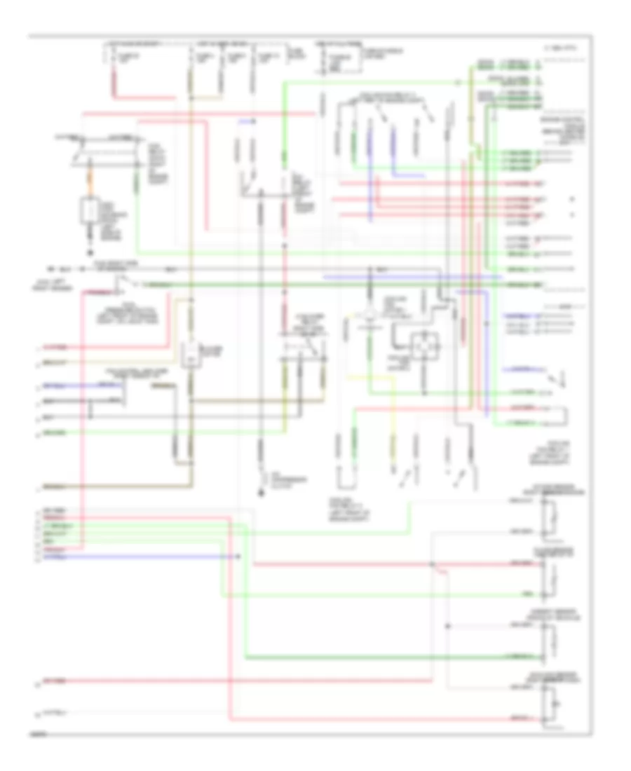
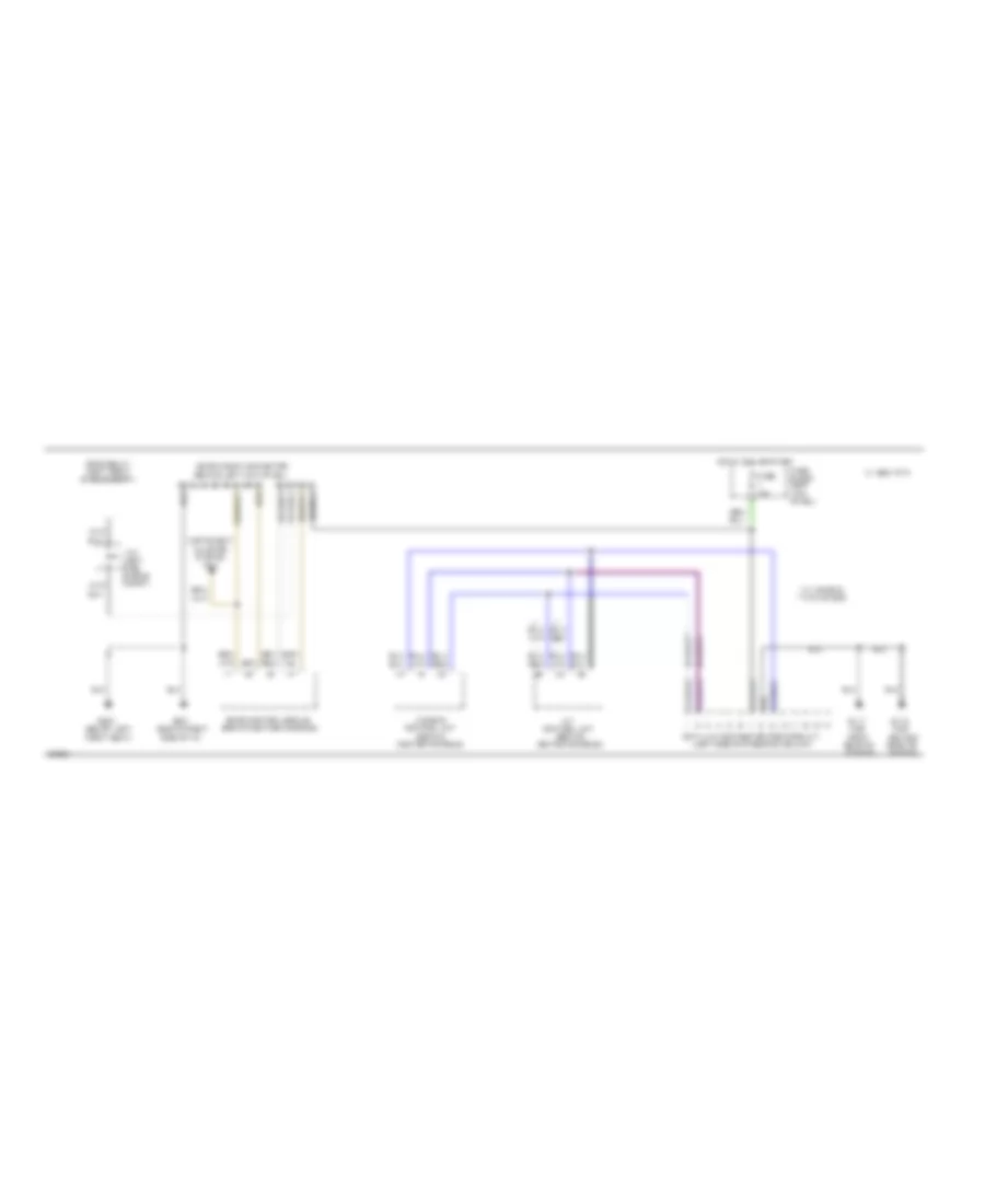
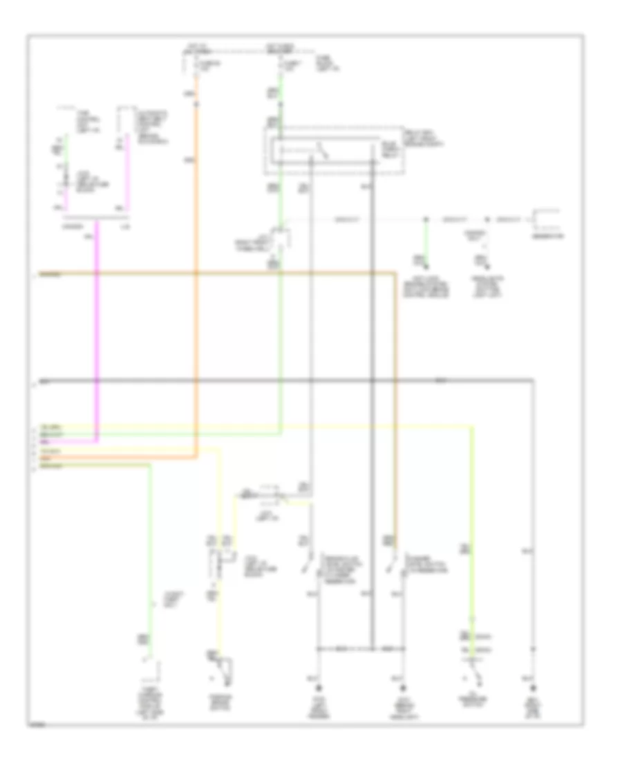
Air Conditioning Wiring Diagrams, Auto A/C (1 of 2) for Nissan Maxima SE 1994
 https://portal-diagnostov.com/license.html
Automotive Electricians Portal FZCO
Automotive Electricians Portal FZCO
https://portal-diagnostov.com/license.html
https://portal-diagnostov.com/license.html
Automotive Electricians Portal FZCO
Automotive Electricians Portal FZCO
List of elements for Air Conditioning Wiring Diagrams, Auto A/C (1 of 2) for Nissan Maxima SE 1994:
- (below g300
- (center of i/p)
- Air mix door motor (center of i/p)
- Auto amp
- B/l
- Def
- Engine control module (behind center console)
- F/d
- Foot
- Fresh vent control illumination
- Fuse 23 10a
- Fuse block
- Hot at all times
- Intake door motor (attached to front of heater unit)
- Interior lights system
- Left front seat)
- Mode door motor (center of i/p)
- Pnk
- Pos sw
- Thermistor
- Thermo control amp (right side of i/p)
- Vent
- Water cock solenoid (center rear of engine)
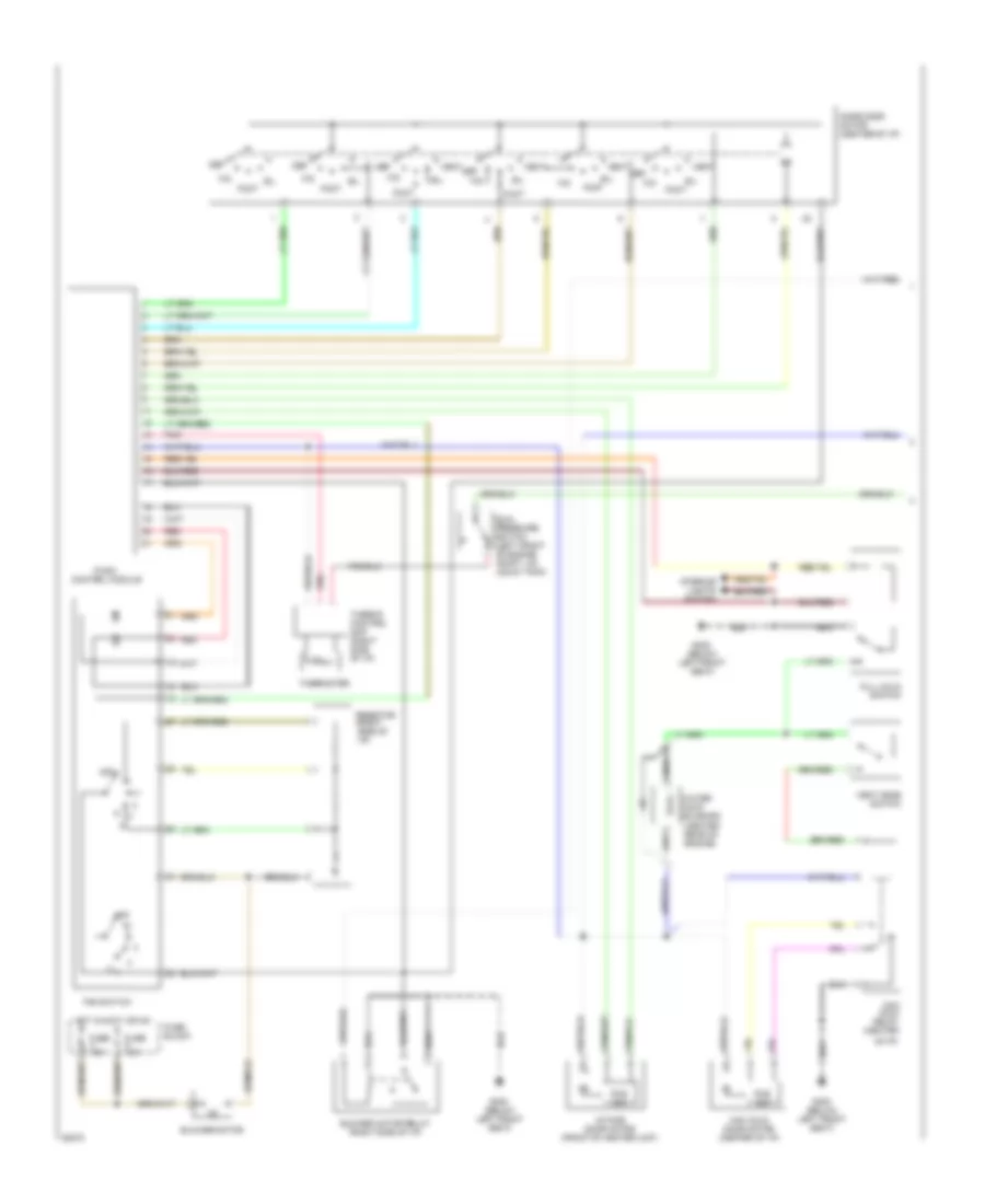
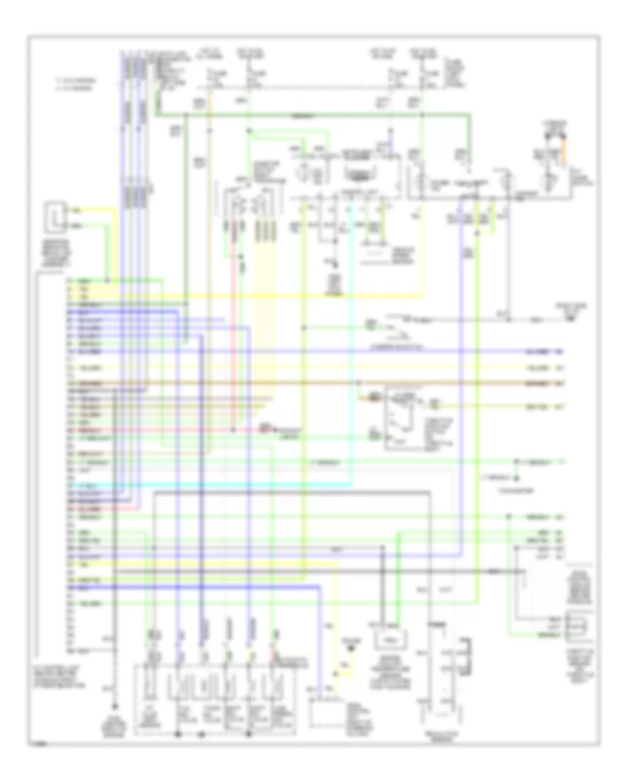
Air Conditioning Wiring Diagrams, Auto A/C (2 of 2) for Nissan Maxima SE 1994
List of elements for Air Conditioning Wiring Diagrams, Auto A/C (2 of 2) for Nissan Maxima SE 1994:
- (dohc)
- (dohc) (sohc)
- (front of vehichle)
- (left front of engine compt)
- (left front of engine compt, on liquid tank)
- (left g100
- (right of engine compt)
- (sohc)
- 1994 vftc c
- A/c compressor clutch
- A/c relay (left front of engine compt)
- Ambient sensor
- Blower motor
- Cooling fan motor 1
- Cooling fan motor 2
- Cooling fan relay 1
- Cooling fan relay 2
- Cooling fan relay 3 (left frnt of engine compt)
- Dual pressure switch
- Engine control module (behind center console)
- Fan control amplifier (right side of i/p)
- Ficd relay
- Front fender)
- Fuse & fusible link box
- Fuse 10 10a
- Fuse 20 10a
- Fuse 4 15a
- Fuse 5 15a
- Fuse block
- Fusible link red
- G120 (right side
- Hi blower relay (right side
- Hot at all times
- Hot in accy or on
- Hot in on or start
- Iacv- ficd solenoid (dohc) (left side of engine)
- In car sensor (center of i/p)
- Intake sensor (right rear of engine)
- J/c 1
- J/c 2
- Of engine)
- Of i/p)
- Sunload sensor (right side of dash)
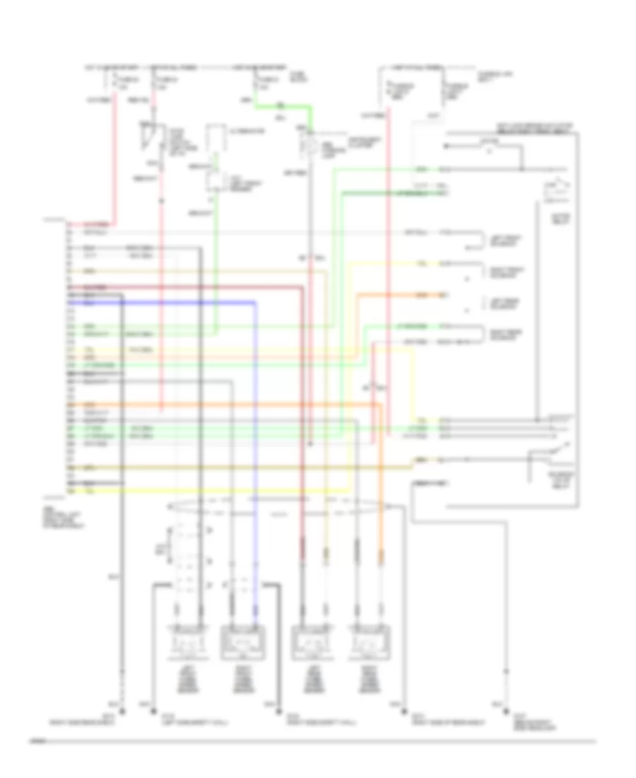
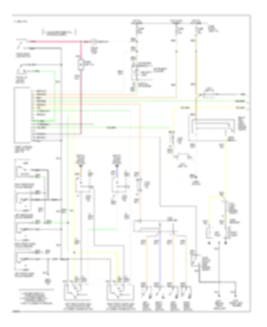
Air Conditioning Wiring Diagrams, Manual A/C (1 of 2) for Nissan Maxima SE 1994
List of elements for Air Conditioning Wiring Diagrams, Manual A/C (1 of 2) for Nissan Maxima SE 1994:
- (below left front seat)
- (center rear of engine)
- B/l
- Blower motor
- Blower motor relay (right side of i/p)
- Def
- Dual pressure switch (left front of engine compt, on liquid tank)
- F/d
- Fan switch
- Foot
- Full cold switch
- Fuse 15a
- Fuse block
- G300
- Hot in accy or on
- Intake door motor (front of heater unit)
- Interior lights system
- Max cold door motor (center of i/p)
- Max cold relay (center
- Mode door motor (center of i/p)
- Of i/p)
- Off
- Pnk
- Pos sw
- Push control module
- Red
- Resistor (right side of i/p)
- Thermister
- Thermo control amp (right side of i/p)
- Vent
- Vent mode switch
- Water cock solenoid
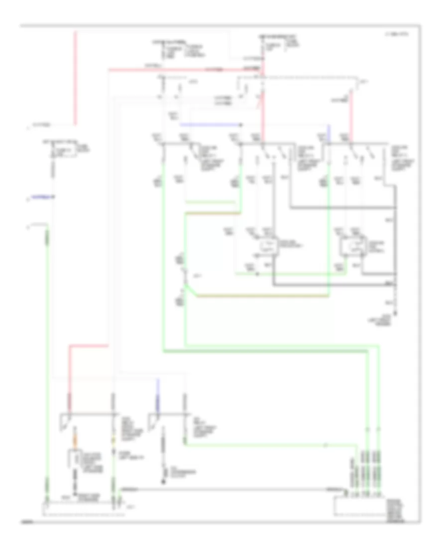
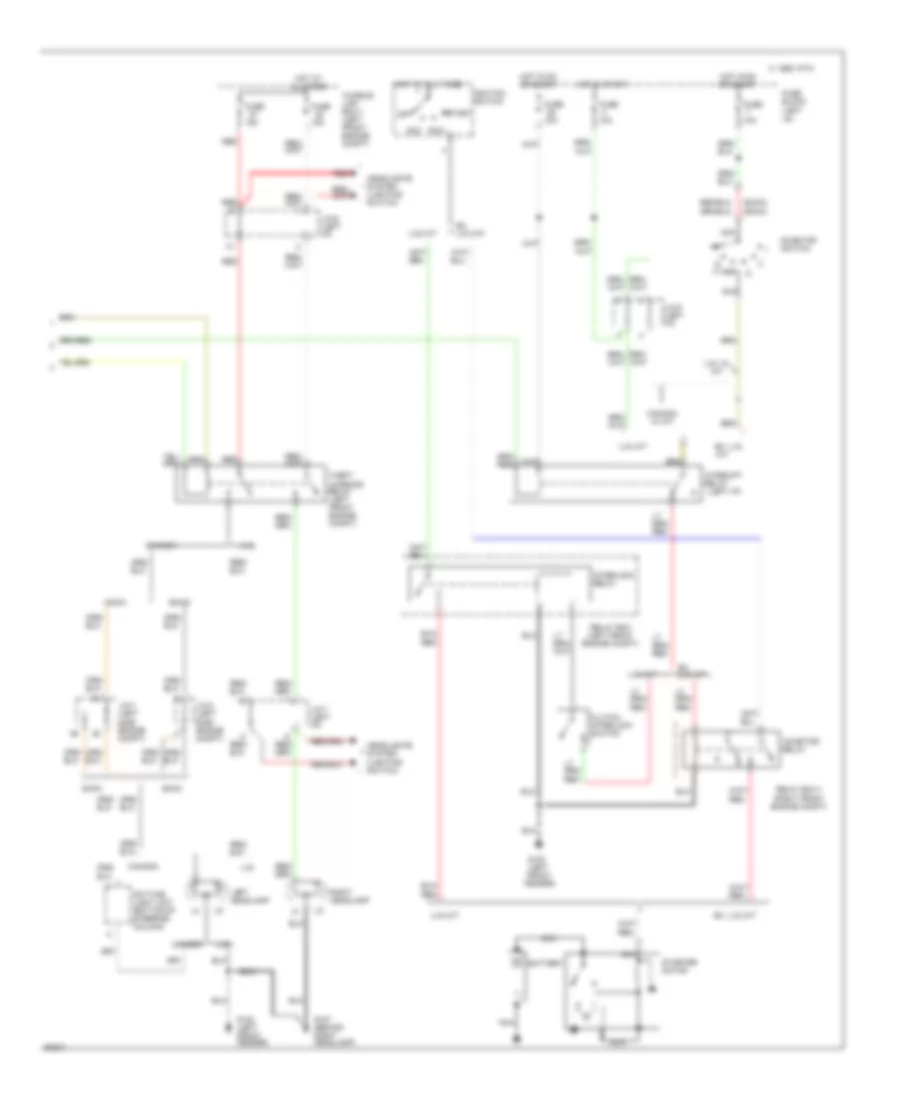
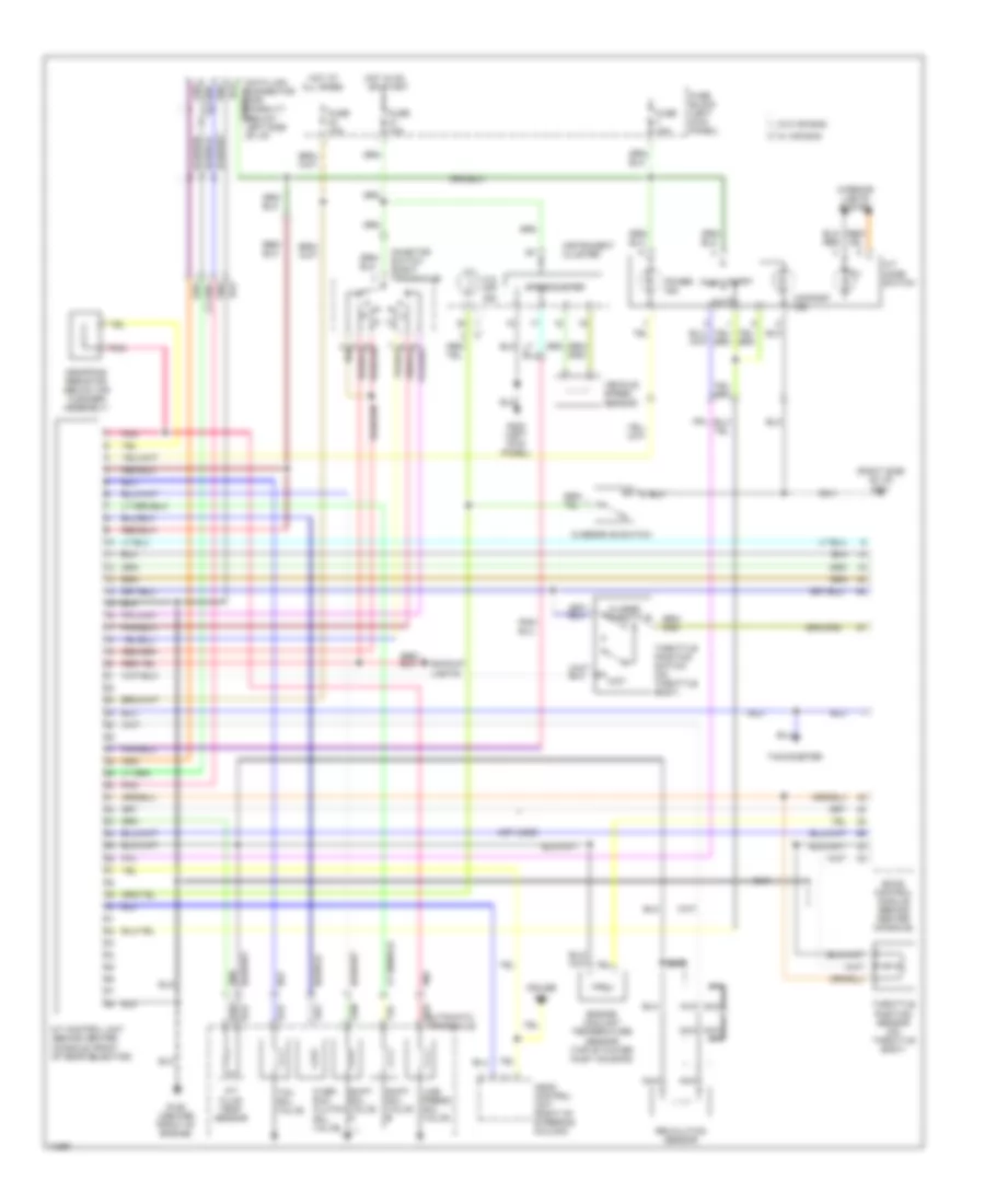
Air Conditioning Wiring Diagrams, Manual A/C (2 of 2) for Nissan Maxima SE 1994
List of elements for Air Conditioning Wiring Diagrams, Manual A/C (2 of 2) for Nissan Maxima SE 1994:
- (dohc)
- (left front of engine compt)
- (right side of engine)
- (sohc)
- 1994 vftc c
- A/c compressor clutch
- A/c relay
- Compt)
- Cooling fan motor 1
- Cooling fan motor 2
- Cooling fan relay 1
- Cooling fan relay 2
- Cooling fan relay 3
- Diode (left side i/p)
- Engine control module (behind center console)
- Ficd relay (dohc) (right side of engine
- Fuse 10 10a
- Fuse 20 10a
- Fuse block
- Fusible link & fuse box
- Fusible link red
- G100 (left front fender)
- G120
- Hot at all times
- Hot in accy or on
- Hot in on or start
- Iacv-ficd solenoid (dohc) (left side of engine)
- J/c 1
- J/c 2
ANTI-LOCK BRAKES
Anti-lock Brake Wiring Diagrams for Nissan Maxima SE 1994
List of elements for Anti-lock Brake Wiring Diagrams for Nissan Maxima SE 1994:
- 10a
- 15a
- Abs control unit (right side of rear shelf)
- Abs warning lamp
- Alternator
- Anti-lock brake actuator (below right front seat)
- B12
- Fuse 20
- Fuse 21
- Fuse 24
- Fuse block
- Fusible link box 1
- G10
- G107 (behind right side headlamp)
- G116 (left side safety wall)
- G123 (right side safety wall)
- G313 (right side of rear shelf)
- G313 (right side rear shelf)
- H10 smj
- Hot at all times
- Hot in on or start
- I10
- Instrument cluster
- J/c-1 (left front fender)
- Left front solenoid
- Left front wheel speed sensor
- Left rear solenoid
- Left rear wheel speed sensor
- Motor
- Motor relay
- Nca
- Right front solenoid
- Right front wheel speed sensor
- Right rear solenoid
- Right rear wheel speed sensor
- Smj
- Solenoid valve relay
- Stop lamp switch (left side of i/p)
ANTI-THEFT
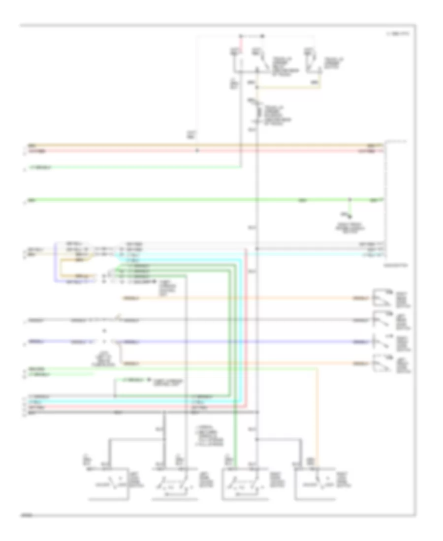
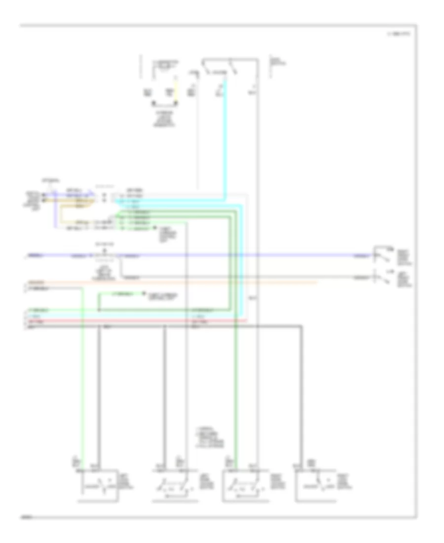
Anti-theft Wiring Diagram (1 of 2) for Nissan Maxima SE 1994
List of elements for Anti-theft Wiring Diagram (1 of 2) for Nissan Maxima SE 1994:
- stroke & normal
- stroke & normal unlock-between full
- (digital) (standard)
- (left i/p)
- (standard) (digital)
- 1995 vftc c
- Control unit
- Digital touch entry control unit
- Diode
- Fuse 10a
- Fuse block (left i/p)
- G100 (front left fender)
- G107 (behind right headlamp)
- G201 (right
- Hood switch (right side engine compt)
- Horn bracket
- Horn relay
- Horn switch
- Hot at all times
- Hot in acc or run
- I/p)
- Instrument cluster
- J/c-1 (left side engine compt)
- J/c-4 (left i/p)
- J/c-8
- J/c-8 (left
- J/c-8 (left i/p)
- J/c-9 (left
- Key cylinder withdrawn
- Left front door lock/ unlock switch & key cylinder tamper switch
- Left front door switch
- Left front door unlock sensor
- Left horn
- Left rear door switch
- Left rear door unlock sensor
- Lock
- Lock-between full
- Pnk
- Relay box (left front engine compt)
- Right front door lock/ unlock switch & key cylinder tamper switch
- Right front door switch
- Right front door unlock sensor
- Right horn
- Right rear door switch
- Right rear door unlock sensor
- Security lamp
- Stroke & normal
- Theft warning
- Trunk lid unlock switch
- Trunk room lamp
- Trunk room lamp switch
- Unlock
- Unlock-between full
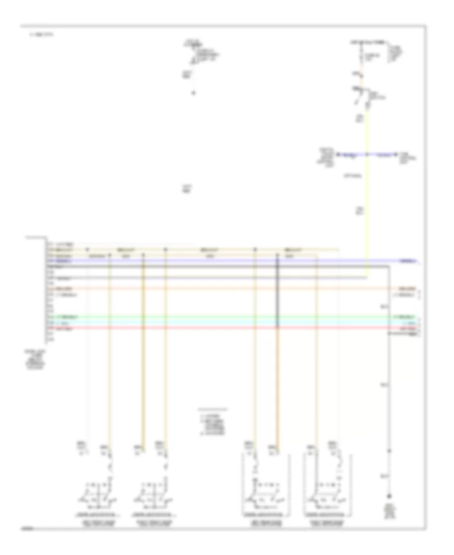
Anti-theft Wiring Diagram (2 of 2) for Nissan Maxima SE 1994
List of elements for Anti-theft Wiring Diagram (2 of 2) for Nissan Maxima SE 1994:
- (dohc)
- (left i/p)
- (sohc)
- 15a
- 1995 vftc c
- Acc
- Battery
- Canada
- Canada w/ m/t
- Clutch interlock switch
- Daytime light unit (bottom of steering column)
- Dohc
- Ex. u.s. -m/t
- Ex. u.s.-m/t
- Fuse
- Fuse 10a
- Fuse block (left
- Fusible link box-1 (left front engine compt)
- G100 (left front fender)
- G107 (behind right headlamp)
- Headlights system (lighting switch)
- Hot at all times
- Hot in on or start
- Hot in start
- I/p)
- Ignition switch
- Inhibitor relay
- Inhibitor switch
- Interlock relay
- Interupt relay
- J/c-1 (left side engine compt)
- J/c-3 (left side engine compt)
- J/c-6 (left i/p)
- J/c-7 (left i/p)
- J/c-9 (left i/p)
- Left headlamp
- Nca
- Off
- Red
- Relay box (left front engine compt)
- Relay box-1 (right front engine compt)
- Right headlamp
- Run
- Sohc
- Start
- Starter motor
- Theft warning relay (left front engine compt)
- U.s.
- U.s. w/ a/t
- U.s.-m/t
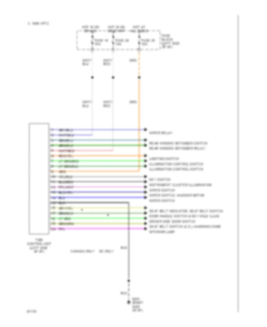
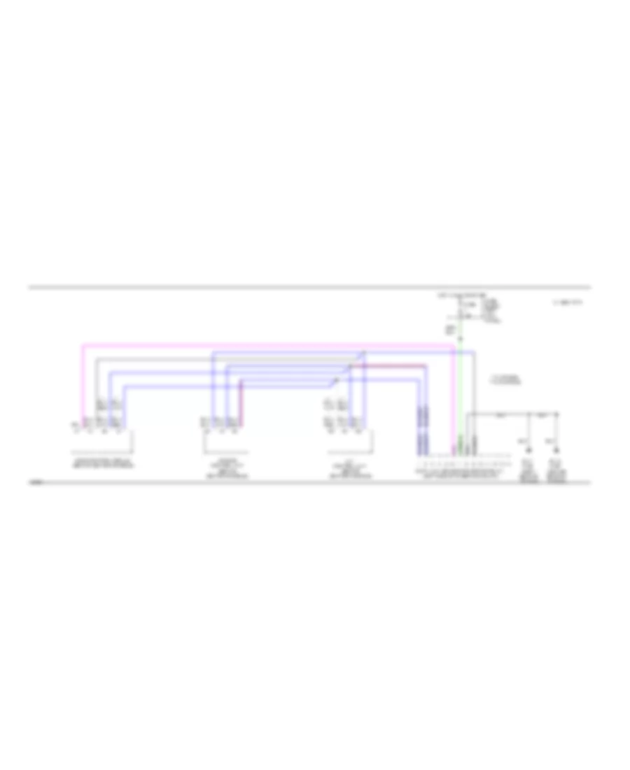
BODY COMPUTER
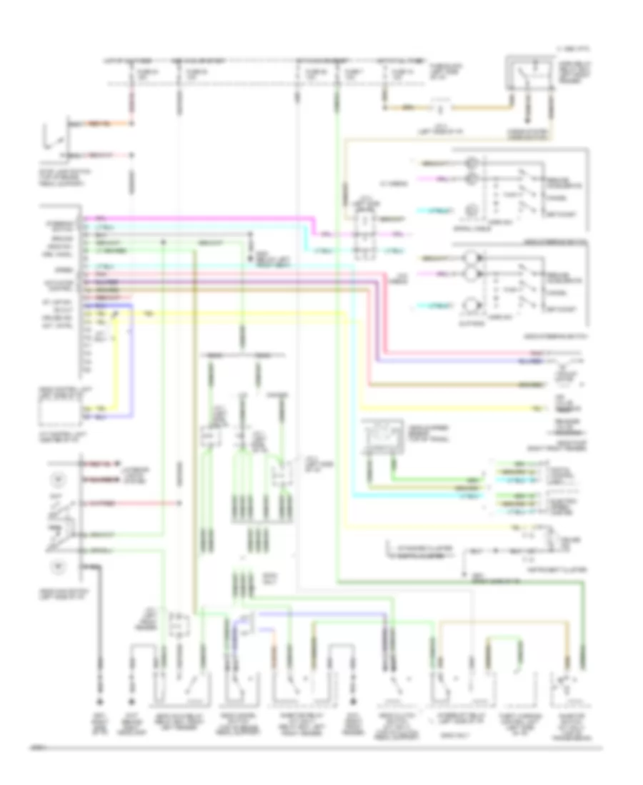
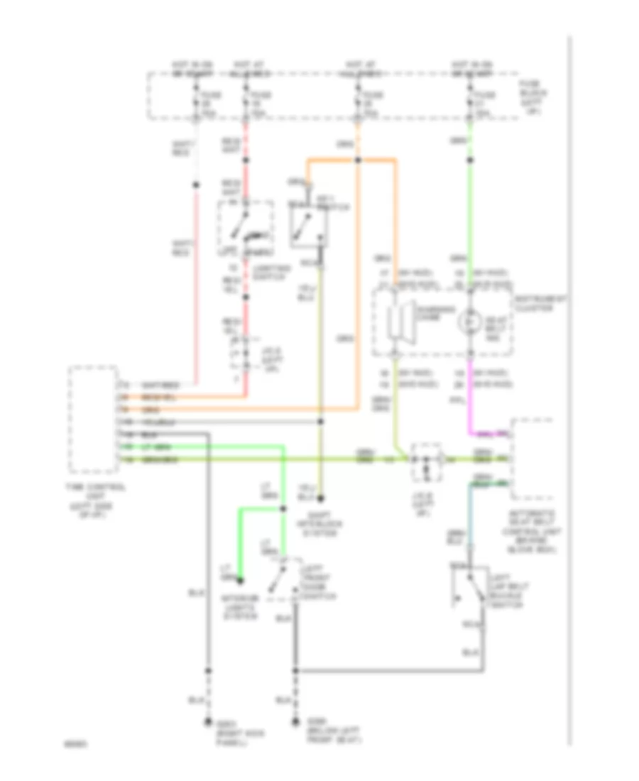
Time Control Unit Wiring Diagram for Nissan Maxima SE 1994
List of elements for Time Control Unit Wiring Diagram for Nissan Maxima SE 1994:
- C 1995 vftc
- Canada only
- Door handle switch & key hole illum.
- Driver side door switch
- Fuse 10 10a
- Fuse 20 10a
- Fuse 25 10a
- Fuse block (left side of i/p)
- G201 (right
- Hot at all times
- Hot in on or acc
- Hot in on or start
- Illumination control switch
- Instrument cluster illumination
- Interior lamp
- Key switch
- Lighting switch
- Rear window defogger relay
- Rear window defogger switch
- Se only
- Seat belt indicator, seat belt switch
- Seat belt switch (u.s.), warning chime
- Side of i/p)
- Time control unit (left side of i/p)
- Wiper relay
- Wiper switch
- Wiper switch, washer motor
COMPUTER DATA LINES
3.0L
3.0L DOHC, Computer Data Lines for Nissan Maxima SE 1994
List of elements for 3.0L DOHC, Computer Data Lines for Nissan Maxima SE 1994:
- (left side of steering column)
- **w/o air bag
- *w/ air bag
- 1995 vftc c
- A/t control unit (behind center console)
- Air bag control unit (behind center console)
- Center rear of engine)
- Data link connector (for consult)
- Eccs control module (behind center console)
- Fuse 10a
- Fuse block (left kick panel)
- G115 (top
- G117 (top right
- Hot in run or start
- Rear of engine)
- Red
3.0L SOHC, Data Link Connector Wiring Diagram for Nissan Maxima SE 1994
List of elements for 3.0L SOHC, Data Link Connector Wiring Diagram for Nissan Maxima SE 1994:
- (behind right
- (below left front seat)
- (left side of steering column)
- **w/o air bag
- *w/ air bag
- 1995 vftc c
- A/t control unit (behind center console)
- Air bag control unit (behind center console)
- Center rear of engine)
- Data link connector (for consult)
- Eccs check connector (behind left kick panel)
- Eccs control module (behind center console)
- Eccs relay (left front engine compt)
- Fuse 10a
- Fuse block (left kick panel)
- G115 (top
- G117 (top right
- G201
- G300
- Hot in run or start
- Instrument cluster system (mil)
- J/c-1 (left side engine compt)
- Rear of engine)
- Red
- Side of i/p)
COOLING FAN
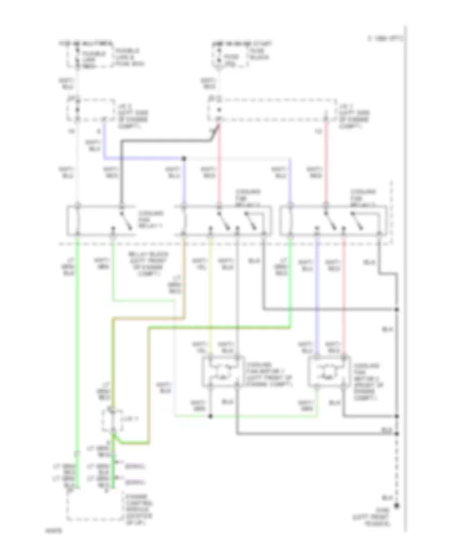
Cooling Fan Wiring Diagram for Nissan Maxima SE 1994
List of elements for Cooling Fan Wiring Diagram for Nissan Maxima SE 1994:
- (dohc)
- (sohc)
- 1994 vftc c
- Cooling fan motor 1 (left front of engine compt)
- Cooling fan motor 2 (front of engine compt)
- Cooling fan relay 1
- Cooling fan relay 2
- Cooling fan relay 3
- Engine control module (center of i/p)
- Fuse 10a
- Fuse block
- Fusible link & fuse box
- Fusible link red
- G100 (left front fender)
- Hot at all times
- Hot in on or start
- J/c 1
- J/c 1 (left side of engine compt)
- J/c 2 (left side of engine compt)
- Relay block (left front of engine compt)
CRUISE CONTROL
Cruise Control Wiring Diagram for Nissan Maxima SE 1994
List of elements for Cruise Control Wiring Diagram for Nissan Maxima SE 1994:
- 1995 vftc c
- A/t
- A/t control unit (center of i/p)
- A/t only
- Act. cntrl
- Actuator control
- Air valve solenoid
- Ascd cancel switch (top of brake pedal support)
- Ascd clutch switch (m/t only) (top of clutch pedal support)
- Ascd control unit (left side of i/p)
- Ascd hold relay (relay box, front left fender)
- Ascd main switch (left side of i/p)
- Ascd pump (right front fender)
- Ascd steering switch
- Ascd sw.
- Canada
- Cancel
- Crs. cancl
- Cruise ind.
- Digital cluster
- Digital control unit
- Dohc
- Dohc only
- Electric speed- ometer
- Fuse 18 10a
- Fuse 20 10a
- Fuse 24 15a
- Fuse 26 10a
- Fuse 7 10a
- Fuse block (left side of i/p)
- G101 (right front fender)
- G107 (behind right headlamp)
- G201 (right side of i/p)
- G300 (below left front seat)
- Ground
- Horn relay (relay box, left front fender)
- Horn sw.
- Horns system (horn switch)
- Hot at all times
- Hot in on or start
- Inhibitor relay (a/t only) (relay box, left front fender)
- Inhibitor switch (a/t only) (top of transmission)
- Instrument cluster
- Interior lights system
- Interrupt relay (left side of i/p)
- J/c 1 (left front fender)
- J/c 1 (left side of i/p)
- J/c 4 (left side of i/p)
- M/t
- Nca
- Od cut
- Off
- Pnk
- Release valve solenoid
- Resume/ accelerate
- Set/coast
- Slip ring
- Sohc
- Speed
- Spiral cable
- St lmp sw.
- Standard cluster
- Steering switch
- Stop lamp switch (top of brake pedal support)
- Theft warning control unit (left side of i/p)
- U.s.
- Vacuum motor
- Vehicle speed sensor (top of trans.)
- W/ airbag
- W/o airbag
DEFOGGERS
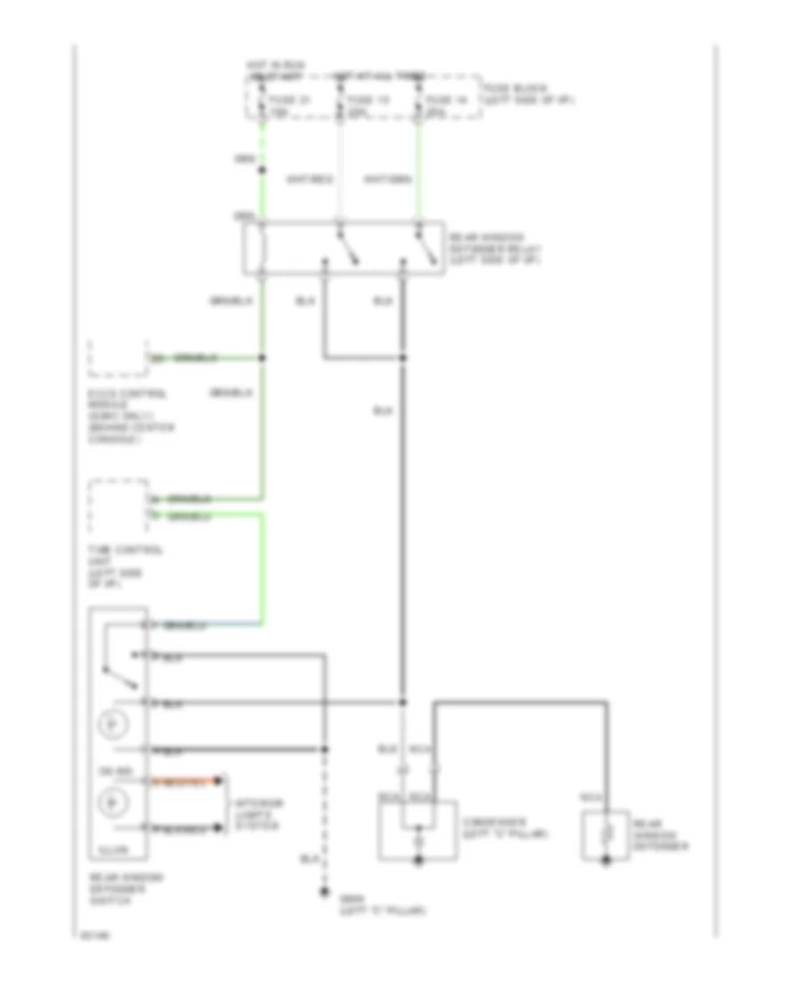
Defogger Wiring Diagram for Nissan Maxima SE 1994
List of elements for Defogger Wiring Diagram for Nissan Maxima SE 1994:
- Condenser (left "c" pillar)
- Eccs control module (sohc only) (behind center console)
- Fuse 14 20a
- Fuse 15 20a
- Fuse 21 10a
- Fuse block (left side of i/p)
- G904 (left "c" pillar)
- Hot at all times
- Hot in run or start
- Illum.
- Interior lights system
- Nca
- On ind.
- Rear window defogger
- Rear window defogger relay (left side of i/p)
- Rear window defogger switch
- Time control unit (left side of i/p)
ENGINE PERFORMANCE
3.0L
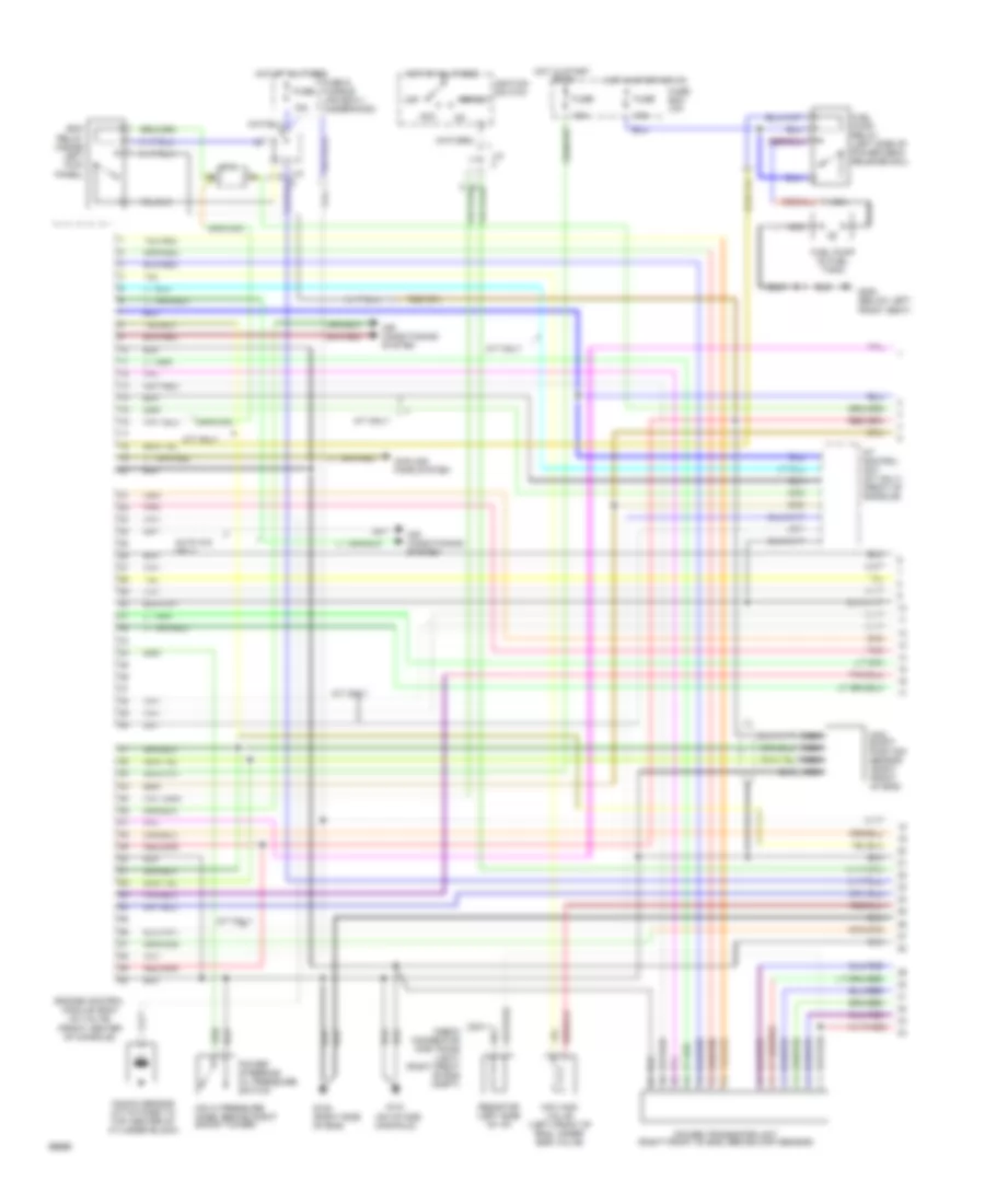
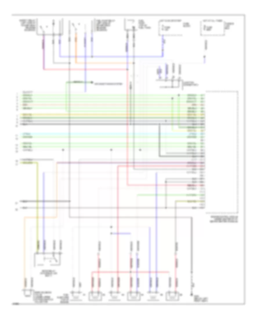
3.0L DOHC, Engine Performance Wiring Diagrams (1 of 2) for Nissan Maxima SE 1994
List of elements for 3.0L DOHC, Engine Performance Wiring Diagrams (1 of 2) for Nissan Maxima SE 1994:
- (on hi pressure hose, behind right shock tower)
- (on intake manifold)
- 10a
- 15a
- A/t control unit (a/t only) (front of console)
- A/t only
- Acc
- Air conditioning system
- Auto a/c only
- Cam- shaft position sensor (right front of eng)
- Check connector (for timing light) (right front of eng compt)
- Cooling fans system
- Ecm relay (inside left kick
- Engine control module (ecm) (24 valve) (front center of console)
- Fuel pump (in fuel tank)
- Fuel pump relay (left side of power deck release sol)
- Fuse
- Fuse & fusible link box-1 (underhood)
- Fuse box (i/p)
- G120 (right side of eng)
- G131
- G300 (below left front seat)
- Hot at all times
- Hot in start
- Hot in start or on
- Iacv-aac valve (left front of eng, under egr valve)
- Ignition switch
- J/c
- J/c-4
- Knock sensor (attatched to top center of cylinder block)
- M/t only
- Nca
- Off
- Or on
- Panel)
- Pnk
- Power steering/ oil pressure switch
- Power transistor unit (right front of eng, behind ckp sensor)
- Resistor (left side of i/p)
- Start
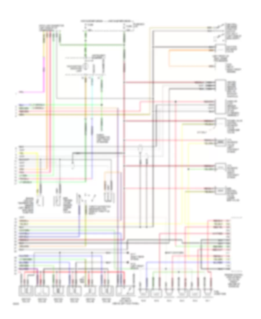
3.0L DOHC, Engine Performance Wiring Diagrams (2 of 2) for Nissan Maxima SE 1994
List of elements for 3.0L DOHC, Engine Performance Wiring Diagrams (2 of 2) for Nissan Maxima SE 1994:
- (left front of eng, under tps sensor)
- 10a
- Check connector (left front of engine)
- Data link connector (left side of i/p, under dash)
- Egr control solenoid valve (under egr valve)
- Egr temper- ature sensor (under egr valve)
- Engine control module (ecm) (24 valve) (front center of console)
- Engine coolant temperature sensor (left rear of eng, near injector)
- Ficd relay (right front fender)
- Fuel injectors
- Fuse
- Fuse box (i/p)
- G110 (left front of eng)
- G117 (right rear of eng)
- Heated oxygen sensor (rear of eng, on exhaust manifold)
- Hot in start or on
- Iacv-ficd solenoid valve
- Ignition coil #1
- Ignition coil #2
- Ignition coil #3
- Ignition coil #4
- Ignition coil #5
- Ignition coil #6
- Ignition coil relay (above left kick panel)
- Instrument cluster
- M/t only
- Malfunction indicator lamp
- Mass air flow sensor (on front of air filter/box assembly)
- Nca
- Neutral/ reverse position switch (m/t only) (left side of eng compt)
- No.1
- No.2
- No.3
- No.4
- No.5
- No.6
- Pnk
- Power valve control solenoid valve (under egr valve)
- Red
- Tachometer
- Throttle position sensor/switch (side of throttle body)
- Vss out
- Vtc solenoid valve (left) (top right of eng)
- Vtc solenoid valve (right) (top right of eng)
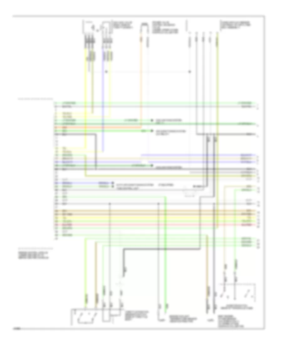
3.0L SOHC, Engine Performance Wiring Diagrams (1 of 3) for Nissan Maxima SE 1994
List of elements for 3.0L SOHC, Engine Performance Wiring Diagrams (1 of 3) for Nissan Maxima SE 1994:
- (a/c relay)
- (if equipped)
- Air conditioning system
- Auto air conditioning system
- Cooling fans system
- Cooling fans system (j/c - 1)
- Egr temper- ature sensor (california only) (in upper intake manifold collector)
- Engine control module (under center of i/p, behind center console)
- Engine coolant temperature sensor (near distributor)
- Iacv-aac valve (right side of throttle body)
- Inhibitor switch (rear of transaxle case)
- Mass air flow sensor (on front of air filter/ box assembly)
- Nca
- Power valve control solenoid valve (under upper intake manifold collector)
- Throttle position sensor & switch (side of throttle body)
- Time control unit
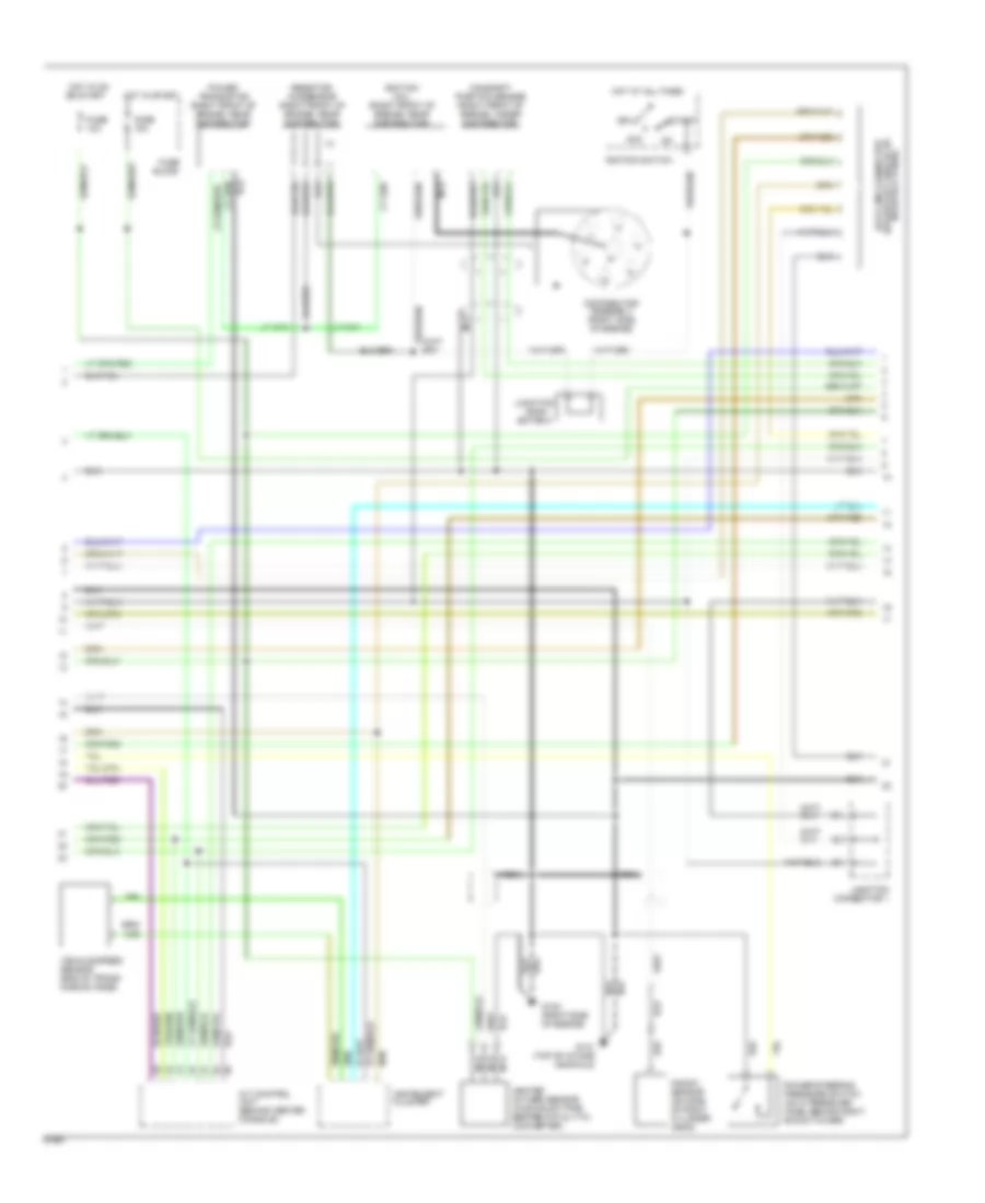
3.0L SOHC, Engine Performance Wiring Diagrams (2 of 3) for Nissan Maxima SE 1994
List of elements for 3.0L SOHC, Engine Performance Wiring Diagrams (2 of 3) for Nissan Maxima SE 1994:
- A/t control unit (behind center console)
- Acc
- Block
- Camshaft position sensor (right front of engine, under distributor)
- Conn-
- Data link connector (below left side of i/p, near kick panel)
- Distributor assembly (right side of engine)
- Ector 5
- Fuse
- Fuse 10a
- G120 (right side of engine)
- G131 (top of intake manifold)
- Heated oxygen sensor (in exhaust pipe before catalytic converter)
- Hot at all times
- Hot in on or start
- Hot in start
- Ignition coil (right front of engine, near distributor)
- Ignition switch
- Instrument cluster
- Junction
- Junction connector 1
- Knock sensor (on side of right cylinder head)
- Nca
- Off
- Power steering pressure switch (on hi pressure hose, behind right shock tower)
- Power transistor (right front of engine, near distributor)
- Resistor/ condensor (right front of engine, near distributor)
- Start
- Vehicle speed sensor (end of trans- mission case)
3.0L SOHC, Engine Performance Wiring Diagrams (3 of 3) for Nissan Maxima SE 1994
List of elements for 3.0L SOHC, Engine Performance Wiring Diagrams (3 of 3) for Nissan Maxima SE 1994:
- Air conditioning system
- Eccs relay (in fusible link box 1)
- Egrc solenoid valve (under upper intake manifold collector)
- Engine control module (under center of i/p, behind center console)
- Fuel injectors (top of engine)
- Fuel pump (top of fuel tank)
- Fuel pump relay (left side of power deck release solenoid)
- Fuse 15a
- Fuse block
- Fusible link box
- G300 (below left front seat)
- Hot at all times
- Hot in on or start
- Junction connector 3
- Nca
- Safety relay (left side of power deck release solenoid)
EXTERIOR LIGHTS
Backup & Turn Lamps Wiring Diagram for Nissan Maxima SE 1994
List of elements for Backup & Turn Lamps Wiring Diagram for Nissan Maxima SE 1994:
- (left side "c" pillar)
- (right side of i/p)
- A/t
- Combination flasher unit (left side of i/p)
- Digital type needle type
- Dohc only
- Fuse 17 10a
- Fuse 21 10a
- Fuse 22 10a
- Fuse block (left side of i/p)
- G100 (left front fender)
- G101 (right front fender)
- G201
- G904
- Hazard
- Hazard switch
- Hot at all times
- Hot in run or start
- Ill.
- Inhibitor switch (on trans)
- Instrument cluster
- Interior lights system
- J/c 1 (left front fender)
- Left front turn light
- Left rear tail/ stop/ turn/ back-up lights
- Left turn ind.
- M/t
- Nca
- Needle type digital type
- Position switch (on trans)
- Right front turn light
- Right rear tail/ stop/ turn/ back-up lights
- Right turn ind.
- Turn signal switch
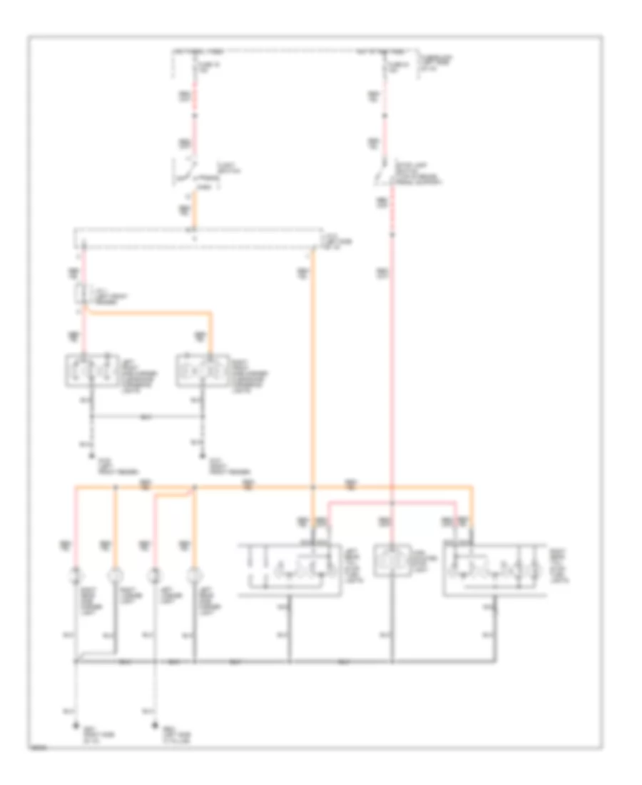
Cornering Lamps Wiring Diagram for Nissan Maxima SE 1994
List of elements for Cornering Lamps Wiring Diagram for Nissan Maxima SE 1994:
- (canada) (us)
- (dohc)
- (sohc)
- (us) (canada)
- Cornering lamp relay (dohc) (right front fender)
- Cornering lamp relay (sohc) (left side kick panel)
- Cornering lamp switch
- Diode (left side of i/p)
- Dohc
- Flash to pass
- Fuse & fusible link box 1 (left front fender)
- Fuse 22 10a
- Fuse 28 15a
- Fuse block (left side of i/p)
- G100 (left front fender)
- G101 (right front fender)
- G203 (right side kick panel)
- Head
- Hi beam
- Hot at all times
- Hot in run or start
- J/c 2 (left front fender)
- J/c 6 (left side of i/p)
- J/c 7 (left side of i/p)
- J/c 7 j/c 5 (left side of i/p)
- Left front side marker/ clearance/ cornering lights
- Light switch
- Off
- Park
- Red
- Right front side marker/ clearance/ cornering lights
- Sohc
Park, Stop & Tail Lamps Wiring Diagram for Nissan Maxima SE 1994
List of elements for Park, Stop & Tail Lamps Wiring Diagram for Nissan Maxima SE 1994:
- Fuse 19 15a
- Fuse 24 15a
- Fuse block (left side of i/p)
- G100 (left front fender)
- G101 (right front fender)
- G201 (right side of i/p)
- G904 (left side "c" pillar)
- Head
- High
- Hot at all times
- J/c 1 (left front fender)
- J/c 5 (left side of i/p)
- Left front side marker/ clearance/ cornering lights
- Left license light
- Left rear side marker light
- Left rear tail/ stop/ turn lights
- Light switch
- Mounted
- Nca
- Off
- Park
- Right front side marker/ clearance/ cornering lights
- Right license light
- Right rear side marker light
- Right rear tail/ stop/ turn lights
- Stop lamp switch (top of brake peadl support)
- Stop light
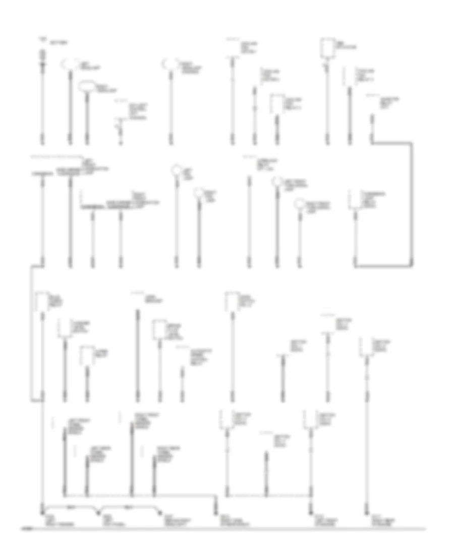
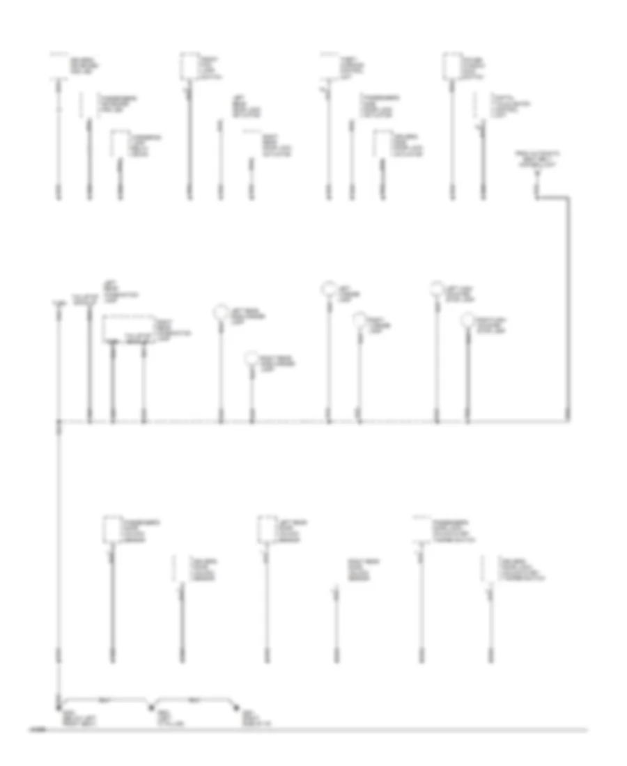
GROUND DISTRIBUTION
Ground Distribution Wiring Diagram (1 of 5) for Nissan Maxima SE 1994
List of elements for Ground Distribution Wiring Diagram (1 of 5) for Nissan Maxima SE 1994:
- (dohc)
- Abs actuator
- Automatic speed control relay
- Battery
- Brake fluid level switch
- Bulb check relay
- Cooling fan motor 1
- Cooling fan motor 2
- Cooling fan relay 2
- Cooling fan relay 3
- Cornering
- Cornering lamp relay (dohc)
- Daylight control unit (canada)
- G100 (left front fender)
- G107 (behind right headlight)
- G110 (left front of engine)
- G117 (right rear of engine)
- G200 (left kick panel)
- G313 (right side of rear shelf)
- Hood switch (no. 2)
- Horn bracket
- Ignition coil 1 (dohc)
- Ignition coil 2
- Ignition coil 3 (dohc)
- Ignition coil 4 (dohc)
- Ignition coil 5 (dohc)
- Ignition coil 6
- Inhibitor relay (a/t)
- Interlock relay (m/t, u.s.)
- Left front combination lamp
- Left fog lamp
- Left front turn signal lamp
- Left front wheel sensor shield
- Left headlamp
- Left rear wheel sensor shield
- Nca
- Right fog lamp
- Right front combination lamp
- Right front turn signal lamp
- Right front wheel sensor shield nca
- Right headlamp
- Right headlamp (canada)
- Right rear wheel sensor shield nca
- Side marker clearance
- Washer level switch
- Wiper relay
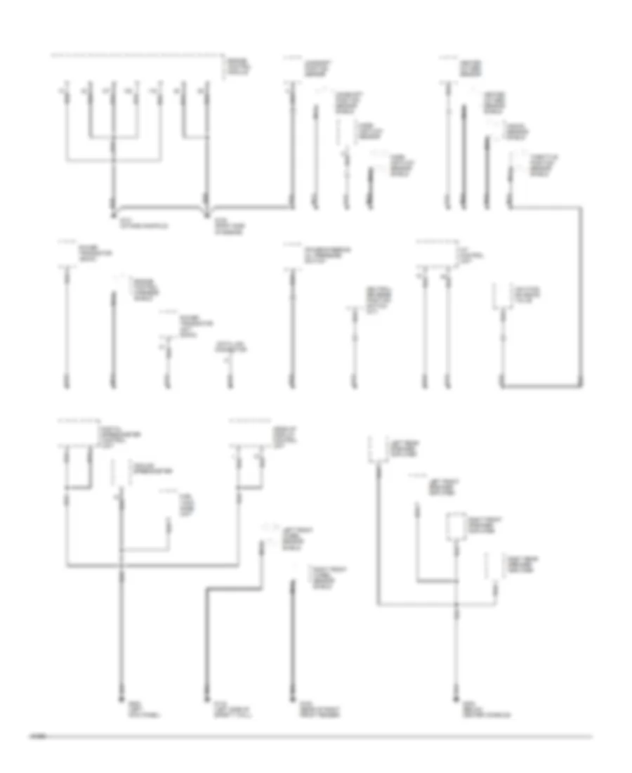
Ground Distribution Wiring Diagram (2 of 5) for Nissan Maxima SE 1994
List of elements for Ground Distribution Wiring Diagram (2 of 5) for Nissan Maxima SE 1994:
- A/t control unit
- Analog speedometer
- Camshaft position sensor
- Camshaft position sensor shield
- Data link connector
- Digital speedometer control unit
- Engine control harness shield
- Engine control module
- Fuel tank gage unit
- G105 (rear of right front fender)
- G116 (left side of safety wall)
- G120 (right side of engine)
- G131 (intake manifold)
- G200 (left kick panel)
- G302 (below center console)
- Head-up display control unit
- Heated oxygen sensor
- Heated oxygen sensor shield
- Iacv-ficd solenoid valve
- Knock sensor shield
- Left front speaker amplifier
- Left front wheel sensor shield
- Left rear speaker amplifier
- Mass air flow sensor
- Mass air flow sensor shield
- Nca
- Neutral/ reverse position switch (m/t)
- Power transistor unit (dohc)
- Power steering oil pressure switch
- Power transistor (sohc)
- Right front speaker amplifier
- Right front wheel sensor shield
- Right rear speaker amplifier
- Throttle position sensor shield
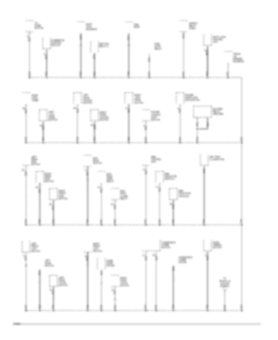
Ground Distribution Wiring Diagram (3 of 5) for Nissan Maxima SE 1994
List of elements for Ground Distribution Wiring Diagram (3 of 5) for Nissan Maxima SE 1994:
- A/t mode switch
- Ash tray illumination
- Blower relay (heater)
- Door lock timer
- Door mirror switch
- Fuel pump
- Fuel pump relay
- Ignition relay 2
- Left lock knob switch
- Left door latch switch
- Left door switch
- Left door unlock switch
- Left front limit switch
- Left rear sub- switch
- Mode door motor
- Nca
- Overdrive control switch
- Power door lock main switch
- Power window main switch
- Right lock knob switch
- Right door latch switch
- Right door unlock switch
- Right front limit switch
- Right front sub- switch
- Right rear sub- switch
- Safety relay (fuel)
- Shift lock control unit
- Shift lock solenoid
- Srs control unit
- Srs indicator (analog)
- Srs indicator (digital)
- Sun roof close relay
- Sun roof open relay
- Sun roof switch
- To trunk lid unlock switch
- Trunk lid opener solenoid
- Windshield wiper motor
- Windshield wiper switch
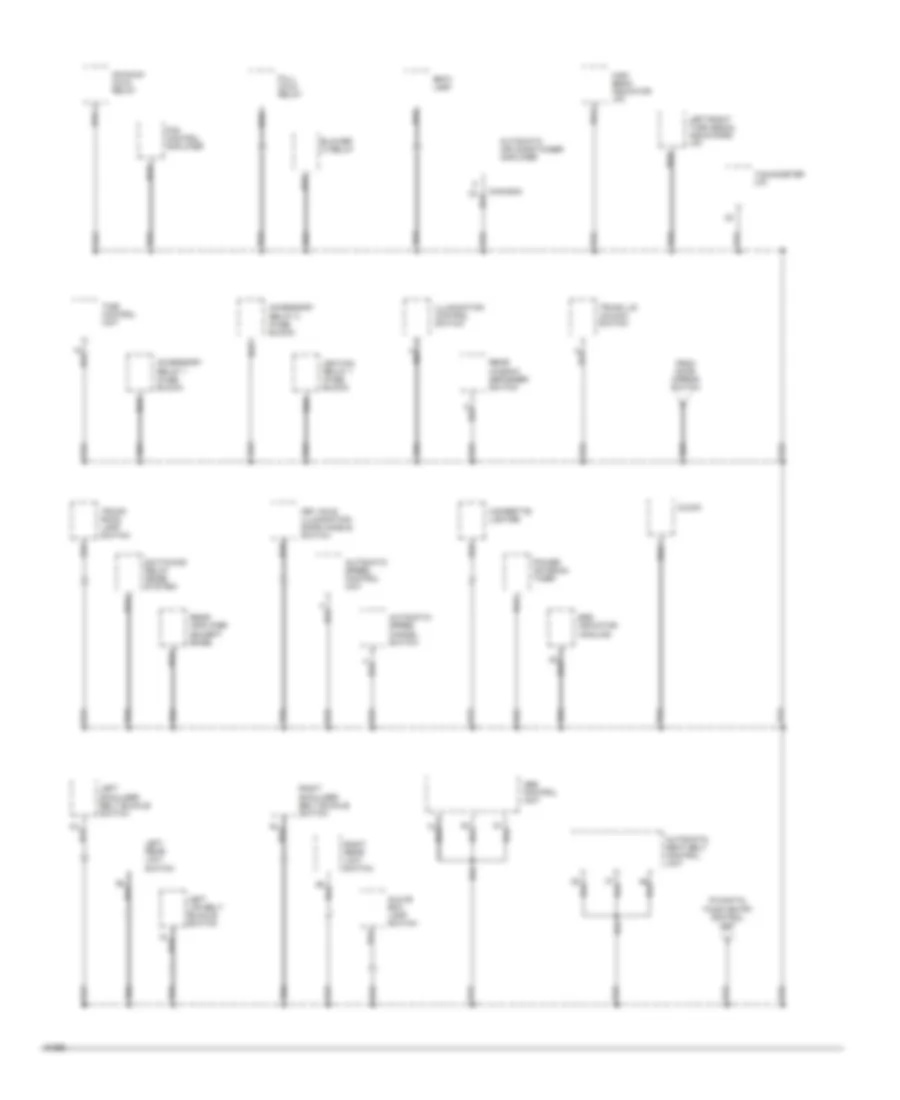
Ground Distribution Wiring Diagram (4 of 5) for Nissan Maxima SE 1994
List of elements for Ground Distribution Wiring Diagram (4 of 5) for Nissan Maxima SE 1994:
- Abs control unit
- Accessory relay 1 (fuse block)
- Accessory relay 2 (fuse block)
- Automatic air conditioner amplifier
- Automatic seat belt control unit
- Automatic speed cancel switch
- Automatic speed control unit
- Blower hi relay
- Cigarette lighter
- Clock
- Fan control amplifier
- From door mirror switch
- Full cold relay
- Glove box lamp switch
- High beam indicator (i/p)
- Ignition relay 1 (fuse block)
- Illumination control switch
- Key hole illumination/ door handle switch
- Left lap belt buckle switch
- Left rear limit switch
- Left shoulder belt buckle switch
- Left/right turn signal indicators (i/p)
- Maximum cold relay
- Power antenna timer
- Rear amplifier (except bose)
- Rear window defogger switch
- Right rear limit switch
- Right shoulder belt buckle switch
- Spot lamp
- Srs indicator (analog)
- Switching relay (bose system)
- Tachometer (i/p)
- Time control unit
- To digital touch entry control unit
- Trunk lid unlock switch
- Trunk room lamp switch
Ground Distribution Wiring Diagram (5 of 5) for Nissan Maxima SE 1994
List of elements for Ground Distribution Wiring Diagram (5 of 5) for Nissan Maxima SE 1994:
- Cornering lamp relay (sohc)
- Digital touch entry control unit
- Driver's door lock/ unlock & key tamper switch
- Driver's door unlock sensor
- Driver's keyboard and led
- Driver's side door lock actuator
- From automatic seat belt control unit
- Front fog lamp switch
- G201 (right side of i/p)
- G300 (below left front seat)
- G904 (left "c" pillar)
- Left rear combination lamp
- Left rear door lock actuator
- Left high- mounted stop lamp
- Left license lamp
- Left rear door unlock sensor
- Left rear side marker lamp
- Passenger's door lock/ unlock & key tamper switch
- Passenger's door unlock sensor
- Passenger's keyboard and led
- Passenger's side door lock actuator
- Power window main switch
- Right license lamp
- Right high- mounted stop lamp
- Right rear combination lamp
- Right rear door lock actuator
- Right rear door unlock sensor
- Right rear side marker lamp
- Tail/stop back-up
- Theft warning control unit
- Turn
HEADLIGHTS
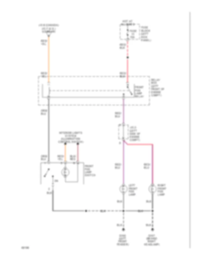
Fog Lamps Wiring Diagram for Nissan Maxima SE 1994
List of elements for Fog Lamps Wiring Diagram for Nissan Maxima SE 1994:
- (behind right headlamp)
- (left front fender)
- 15a
- Front fog lamp relay
- Front fog lamp switch
- Fuse
- Fuse block (left kick panel)
- G100
- G107
- Hot at all times
- Interior lights system (illumination control switch)
- J/c-3 (left side of engine compt)
- J/c-6 (canada)
- J/c-7 (u.s.) (lo beam)
- Left front fog lamp
- Relay box (left front of engine compt)
- Right front fog lamp
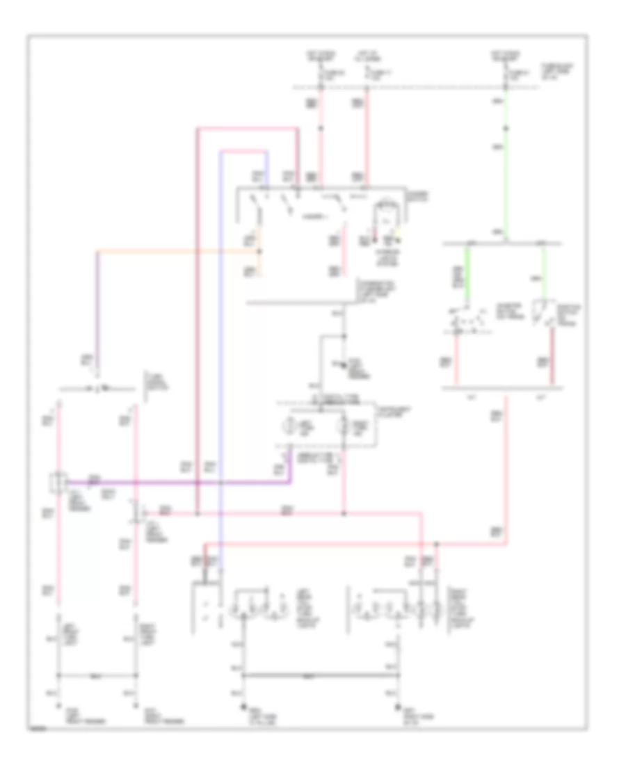
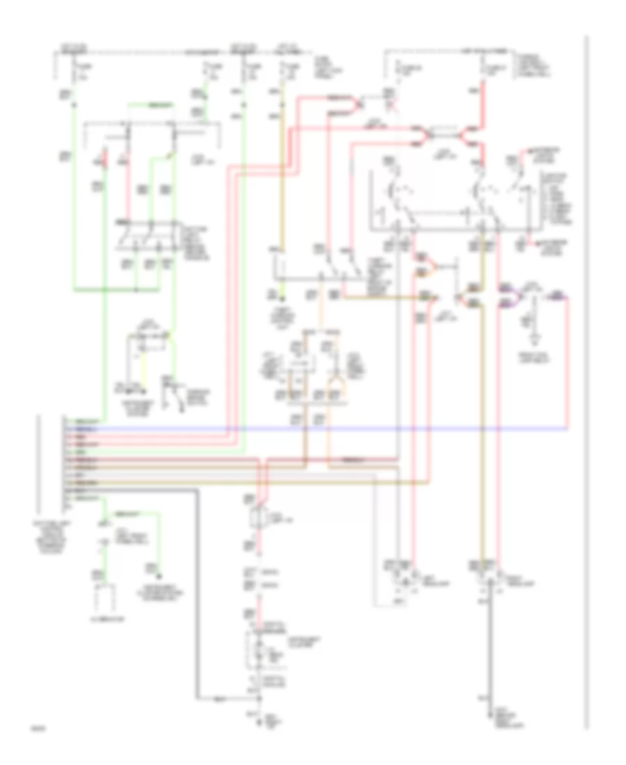
Headlamps Wiring Diagram, with DRL for Nissan Maxima SE 1994
List of elements for Headlamps Wiring Diagram, with DRL for Nissan Maxima SE 1994:
- (digital) (analog)
- (dohc)
- (left front
- (left i/p)
- (sohc)
- 10a
- Alternator
- Daytime light control module (bottom of steering column)
- Daytime light relay (behind center console)
- Dohc
- Exterior lights system
- Front fog lamp relay
- Fuse
- Fuse 27 15a
- Fuse 28 15a
- Fuse block (left kick panel)
- Fusible link box-1 (left front
- G107 (behind right headlamp)
- G201 (right i/p)
- Hi beam ind.
- Hot at all times
- Hot in on or start
- Hot in start
- Instrument cluster
- Instrument cluster system
- Instrument cluster system (charge ind.)
- J/c-1
- J/c-1 (left front wheelwell)
- J/c-3 (left front wheel- well)
- J/c-5 (left i/p)
- J/c-6
- J/c-7
- J/c-8
- J/c-9 (left i/p)
- Left headlamp
- Lighting switch
- Off
- Park head lo beam hi beam flash- to-pass
- Parking brake switch
- Red
- Right headlamp
- Sohc
- Theft warning control unit
- Theft warning relay (left front of engine compt)
- Well)
- Wheel-
- Wheelwell)
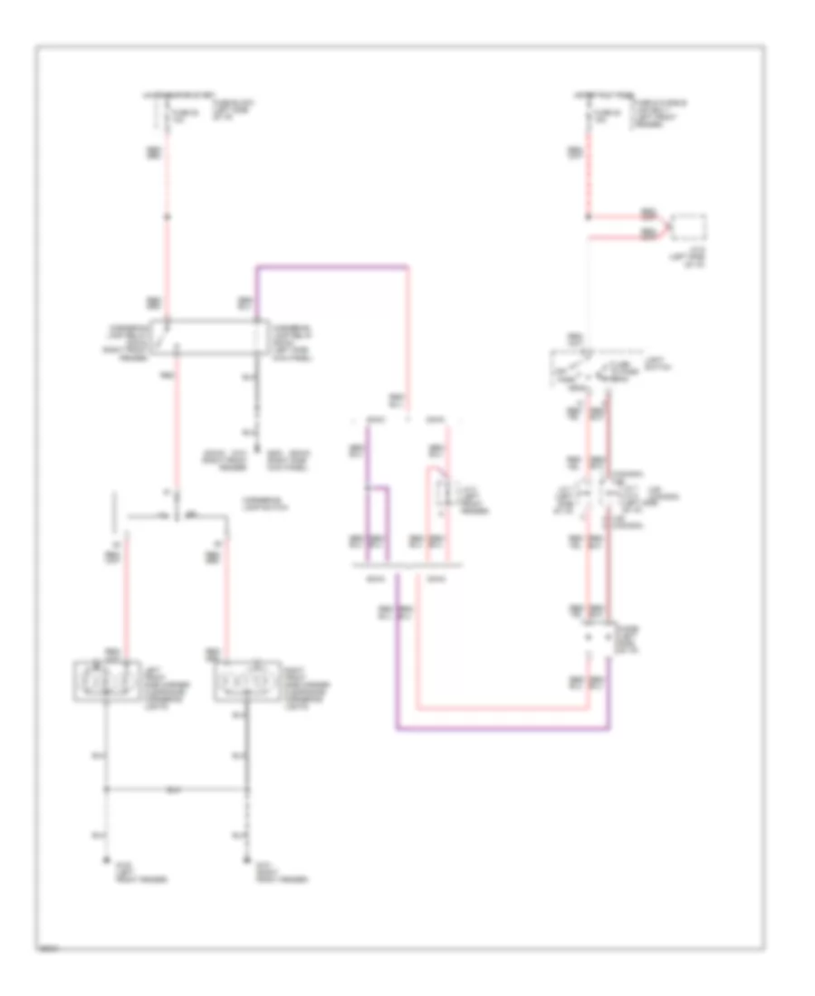
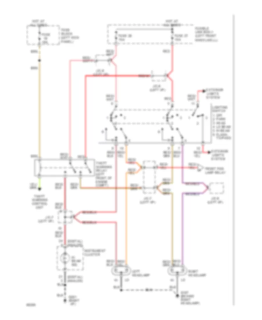
Headlamps Wiring Diagram, without DRL for Nissan Maxima SE 1994
List of elements for Headlamps Wiring Diagram, without DRL for Nissan Maxima SE 1994:
- (digital) (analog)
- (left i/p)
- 10a
- Exterior lights system
- Front fog lamp relay
- Fuse
- Fuse 27 15a
- Fuse 28 15a
- Fuse block (left kick panel)
- Fusible link box-1 (left front
- G107 (behind right headlamp)
- G201 (right i/p)
- Hi beam ind.
- Hot at all times
- Instrument cluster
- J/c-6
- J/c-7
- Left headlamp
- Lighting switch
- Off
- Park head lo beam hi beam flash- to-pass
- Red
- Right headlamp
- Theft warning control unit
- Theft warning relay (left front of engine compt)
- Wheelwell)
HORN
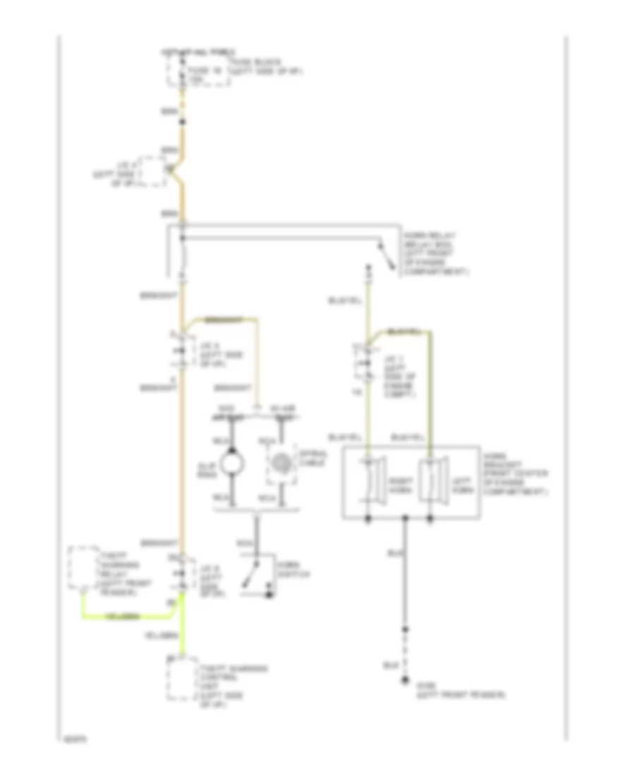
Horn Wiring Diagram for Nissan Maxima SE 1994
List of elements for Horn Wiring Diagram for Nissan Maxima SE 1994:
- Fuse 18 10a
- Fuse block (left side of i/p)
- G100 (left front fender)
- Horn bracket (front center of engine compartment)
- Horn relay (relay box, left front of engine compartment)
- Horn switch
- Hot at all times
- J/c 1 (left side of engine compt)
- J/c 4 (left side of i/p)
- J/c 8 (left side of i/p)
- Left horn
- Nca
- Right horn
- Slip ring
- Spiral cable
- Theft warning control unit (left side of i/p)
- Theft warning relay (left front fender)
- W/ air bag
- W/o air bag
INSTRUMENT CLUSTER
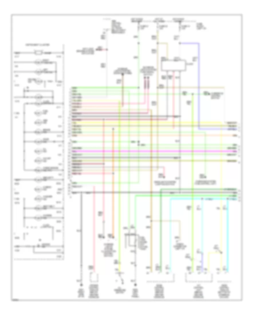
Instrument Cluster Wiring Diagram, with Head-Up Display (1 of 2) for Nissan Maxima SE 1994
List of elements for Instrument Cluster Wiring Diagram, with Head-Up Display (1 of 2) for Nissan Maxima SE 1994:
- (actuator)
- (mil)
- (time control unit)
- A-1
- A-10
- A-11
- A-12
- A-13
- A-15
- A-16
- A-17
- A-2
- A-3
- A-4
- A-5
- A-6
- A-7
- A-8
- A-9
- A/t control unit (behind center console)
- A/t only
- Abs control module (in trunk, below right rear shelf)
- Abs ind.
- Air bag control module (below center console)
- Air bag ind.
- Anti-lock
- Ascd control module (bottom of steering column)
- B-16
- B-18
- B-19
- B-20
- B-21
- B-22
- B-23
- B-24
- B-25
- B-26
- Bat
- Brake ind.
- Brakes system
- C-28
- C-29
- C-31
- Charge ind.
- Check connector (left i/p)
- Check engine ind.
- Chime
- Clock
- Cruise ind.
- Door ind.
- Eccs control module (behind center console)
- Exterior
- Fuel ind.
- Fuel tank gauge unit (in fuel tank)
- Fuse 10 10a
- Fuse 21 10a
- Fuse 23 10a
- Fuse block (left i/p)
- G200 (left kick panel)
- G201 (right side of i/p)
- Gnd
- Headlights system (lighting switch)
- Hi beam ind.
- Hot at all times
- Hot in run or acc
- Hot in run or start
- Ign
- Illum- ination
- Instrument cluster
- Interior lights system (door switches)
- Interior lights system (illumination control switch)
- Left turn ind.
- Lights system (turn signal
- Nca
- O/d off ind.
- Oil ind.
- Oil pressure switch
- Overdrive control switch
- Right turn ind.
- Seat belt ind.
- Security ind.
- Switch)
- Warnings system
- Washer ind.
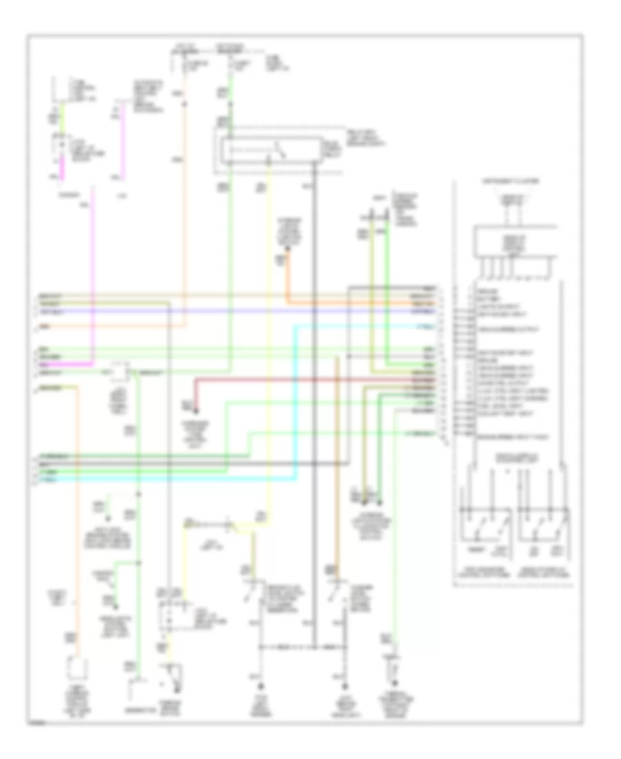
Instrument Cluster Wiring Diagram, with Head-Up Display (2 of 2) for Nissan Maxima SE 1994
List of elements for Instrument Cluster Wiring Diagram, with Head-Up Display (2 of 2) for Nissan Maxima SE 1994:
- (in master
- (left i/p)
- (right front wheel- well)
- Anti-lock brakes system (anti-lock brake control module)
- Automatic seat belt control unit (behind glove box)
- Battery
- Brake fluid level switch
- Bulb check relay
- Canada
- Canada only
- Chime ctrl output
- Coolant temp. input
- Cylinder
- Digital display & control unit
- Engine speed input (tach)
- Fuel level input
- Fuse 25 10a
- Fuse 7 10a
- Fuse block (left i/p)
- G100 (left front fender)
- G107 (behind right headlight)
- Generator
- Ground
- Head-up display
- Head-up display control switches
- Head-up display control unit
- Headlights system (daytime light unit)
- Hot at all times
- Hot in run or start
- Ignition/acc input
- Ignition/start input
- Illum. ctrl input (darken)
- Illum. ctrl input (lighten)
- Instrument cluster
- Interior lights system (illumination control switch)
- Interior lights system (lighting switch)
- J/c-1
- J/c-4
- J/c-8 (left i/p, above fuse block)
- J/c-9 (left i/p, above fuse block)
- Lights on input
- Mph- km/h
- Nca
- On- off
- Parking brake switch
- Relay box (left front engine compt)
- Reservoir)
- Reset
- Theft warning control module (left side of i/p)
- Thermal transmitter (top right front of engine)
- Time control unit (left i/p)
- Trip odometer control switches
- Trip- total
- U.s.
- Vehicle speed input
- Vehicle speed output
- Vehicle speed sensor (on trans- mission)
- W/anti- theft only
- Warnings system (time control unit)
- Washer level switch (in res- ervoir)
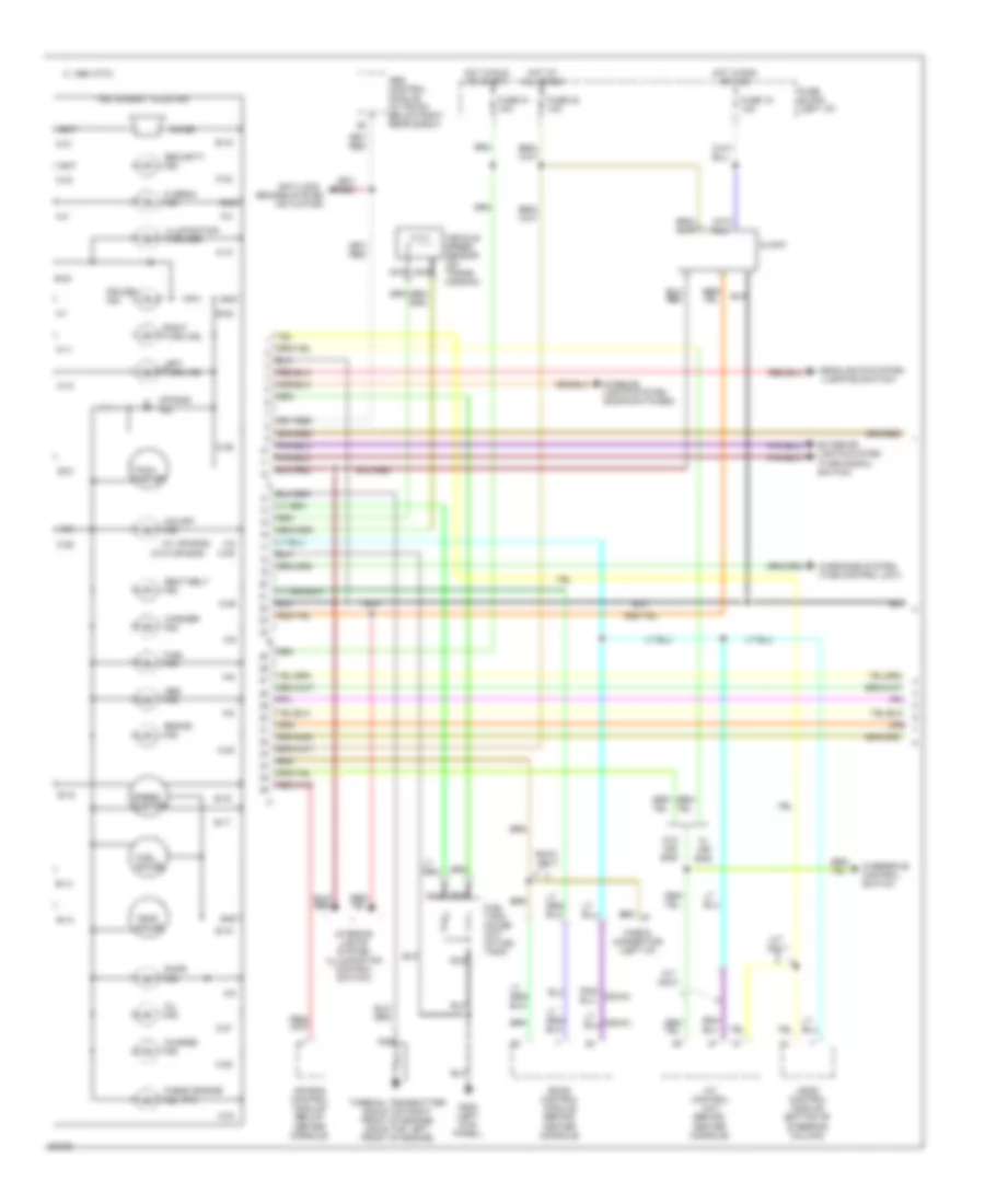
Instrument Cluster Wiring Diagram, without Head-Up Display (1 of 2) for Nissan Maxima SE 1994
List of elements for Instrument Cluster Wiring Diagram, without Head-Up Display (1 of 2) for Nissan Maxima SE 1994:
- (actuator)
- (dohc)
- (door switches)
- (mil)
- (sohc)
- (w/ air bag)
- (w/o air bag)
- 1995 vftc c
- A-1
- A-10
- A-11
- A-12
- A-2
- A-3
- A-4
- A-5
- A-6
- A-8
- A-9
- A/t control unit (behind center console)
- A/t only
- Abs control module (in trunk, below right rear shelf)
- Abs ind.
- Air bag control module (below center console)
- Air bag ind.
- Anti-lock
- Ascd control module (bottom of steering column)
- B-13
- B-14
- B-15
- B-16
- B-17
- B-18
- B-19
- B-21
- B-22
- B-23
- Bat
- Brake ind.
- Brakes system
- C-25
- C-27
- C-28
- C-29
- C-30
- C-31
- C-32
- C-33
- C-34
- C-35
- C-36
- Charge ind.
- Check connector (left i/p)
- Check engine ind.
- Chime
- Clock
- Cruise ind.
- Door ind.
- Eccs control module (behind center console)
- Exterior lights system (turn signal switch)
- Fuel gauge
- Fuel ind.
- Fuel tank gauge unit (in fuel tank)
- Fuse 10 10a
- Fuse 21 10a
- Fuse 23 10a
- Fuse block (left i/p)
- G200 (left kick panel)
- Gnd
- Headlights system (lighting switch)
- Hi beam ind.
- Hot at all times
- Hot in run or acc
- Hot in run or start
- Ign
- Illumination (4 bulbs)
- Instrument cluster
- Interior
- Interior lights system (illumination control switch)
- Left turn ind.
- Lights system
- Nca
- O/d off ind.
- Oil ind.
- Overdrive control switch
- Right turn ind.
- Seat belt ind.
- Security ind.
- Sohc only
- Speed- ometer
- Tach- ometer
- Temp. gauge
- Thermal transmitter (sohc-top right front of engine) (dohc-top left front of engine)
- Vehicle speed sensor (on trans- mission)
- W/ air bag
- W/o air bag
- Warnings system (time control unit)
- Washer ind.
Instrument Cluster Wiring Diagram, without Head-Up Display (2 of 2) for Nissan Maxima SE 1994
List of elements for Instrument Cluster Wiring Diagram, without Head-Up Display (2 of 2) for Nissan Maxima SE 1994:
- (dohc)
- (in master
- (left i/p)
- (sohc)
- Anti-lock brakes system (anti-lock brake control module)
- Automatic seat belt control unit (behind glove box)
- Brake fluid level switch
- Bulb check relay
- Canada
- Canada only
- Cylinder
- Fuse 25 10a
- Fuse 7 10a
- Fuse block (left i/p)
- G100 (left front fender)
- G107 (behind right headlight)
- G201 (right side of i/p)
- Generator
- Headlights system (daytime light unit)
- Hot at all times
- Hot in run or start
- J/c-1 (right front wheelwell)
- J/c-4
- J/c-8 (left i/p, above fuse block)
- J/c-9 (left i/p, above fuse block)
- Level switch (in reservoir)
- Oil pressure switch
- Parking brake switch
- Relay box (left front engine compt)
- Reservoir)
- Theft only
- Theft warning control module (left side of i/p)
- Time control unit (left i/p)
- U.s.
- W/anti-
- Washer
INTERIOR LIGHTS
Courtesy Lamps Wiring Diagram for Nissan Maxima SE 1994
List of elements for Courtesy Lamps Wiring Diagram for Nissan Maxima SE 1994:
- Air bag control unit
- Door
- Door handle switch & key hole illum. (se model)
- Fuse 23 10a
- Fuse 25 10a
- Fuse block (left i/p)
- G201 (right i/p)
- Hot at all times
- Interior lamp
- J/c-8 (left i/p)
- J/c-9 (left i/p)
- Key illum.
- Left front door switch
- Left front step lamp
- Left rear door switch
- Left rear step lamp
- Off
- Pnk
- Right front door switch
- Right front step lamp
- Right rear door switch
- Right rear step lamp
- Spot lamp
- Time control unit (left i/p)
- Trunk room lamp
- Trunk room lamp switch
Instrument Illumination Wiring Diagram for Nissan Maxima SE 1994
List of elements for Instrument Illumination Wiring Diagram for Nissan Maxima SE 1994:
- A/t ind. illum.
- A/t mode switch
- A/t only
- Ascd main switch
- Ashtray
- Auto a/c
- Auto amp.
- Canada
- Cigarette lighter illum.
- Clock
- Darken
- Digital cluster
- Fan switch
- Fresh vent control illum.
- Front fog lamp switch
- Fuse 19 10a
- Fuse 21 10a
- Fuse block (left i/p)
- G201 (right i/p)
- Glove box lamp
- Glove box switch
- Hazard switch
- Head
- Head-up display control unit
- Hot at all times
- Hot in on or start
- Ill.
- Illum.
- Illumination control switch
- Instrument cluster
- J/c-5 (left i/p)
- Lighten
- Lighting switch
- Main switch illum.
- Manual a/c
- Nca
- Off
- Park
- Push control unit
- Radio
- Rear window defogger switch
- Red
- Standard cluster
- Standard cluster only
- Time control module (left kick panel)
- U.s.
- W/ digital cluster
PASSIVE RESTRAINTS
Passive Restraint Wiring Diagram for Nissan Maxima SE 1994
List of elements for Passive Restraint Wiring Diagram for Nissan Maxima SE 1994:
- 10a
- 1995 vftc c
- Automatic seat belt control unit (right side of i/p)
- Circuit breaker 1 (left side of i/p)
- Fuse 21
- Fuse 23
- Fuse 25
- Fuse 26
- Fuse block (left side of i/p)
- G300 (below left front seat)
- Hot at all times
- Hot in on or start
- Instrument cluster
- J/c 8 (left side of i/p)
- Left door latch switch (left door)
- Left drive motor (left "b" pillar)
- Left front limit switch (left "a" pillar)
- Left lap belt buckle switch (right side of left seat)
- Left rear limit sw (left "b" pillar)
- Left shoulder belt buckle switch (left "b" pillar)
- Nca
- Right door latch switch (right door)
- Right drive motor (right "b" pillar)
- Right front limit switch (right "a" pillar)
- Right rear limit switch (right "b" pillar)
- Right shoulder belt buckle switch (right "b" pillar)
- Seat belt warning lamp
- Time control unit (left side of i/p)
- Warning chime
POWER ANTENNA
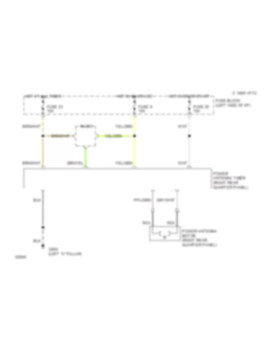
Power Antenna Wiring Diagram for Nissan Maxima SE 1994
List of elements for Power Antenna Wiring Diagram for Nissan Maxima SE 1994:
- 1995 vftc c
- Fuse 23 10a
- Fuse 26 10a
- Fuse 9 10a
- Fuse block (left side of i/p)
- G904 (left "c" pillar)
- Hot at all times
- Hot in on or acc
- Hot in on or start
- Nca
- Power antenna motor (right rear quarter panel)
- Power antenna timer (right rear quarter panel)
- Radio
POWER DISTRIBUTION
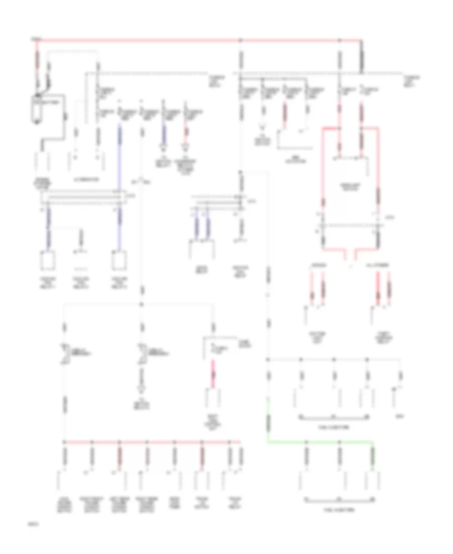
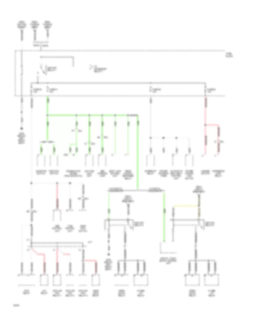
Power Distribution Wiring Diagram (1 of 6) for Nissan Maxima SE 1994
List of elements for Power Distribution Wiring Diagram (1 of 6) for Nissan Maxima SE 1994:
- Abs actuator
- All others
- Alternator
- Battery
- Canada
- Circuit breaker-1
- Circuit breaker-2
- Cooling fan relay-1
- Cooling fan relay-2
- Cooling fan relay-3
- Daytime light unit
- Dohc
- Door lock timer
- E11
- Eccs relay
- Ecm
- Engine starter motor
- Fuel injectors
- Fuse 2 10a
- Fuse 27 15a
- Fuse 28 15a
- Fuse 29 10a
- Fuse block
- Fusible link box-1
- Fusible link box-2
- Fusible link g red
- Fusible link h red
- Headlight switch
- Ignition coil relay
- J/c 2
- J/c 3
- J/c 6
- Left rear power window switch
- Main power window switch
- Nca
- Pnk
- Red
- Right front power window switch
- Right rear power window switch
- Shift lock control unit
- Smj
- Theft warning relay
- To accessory relay-2, & fuses 14-16
- To ignition relay-1
- To ignition relay-2
- To ignition switch
- Trunk lid relay
- Trunk lid switch
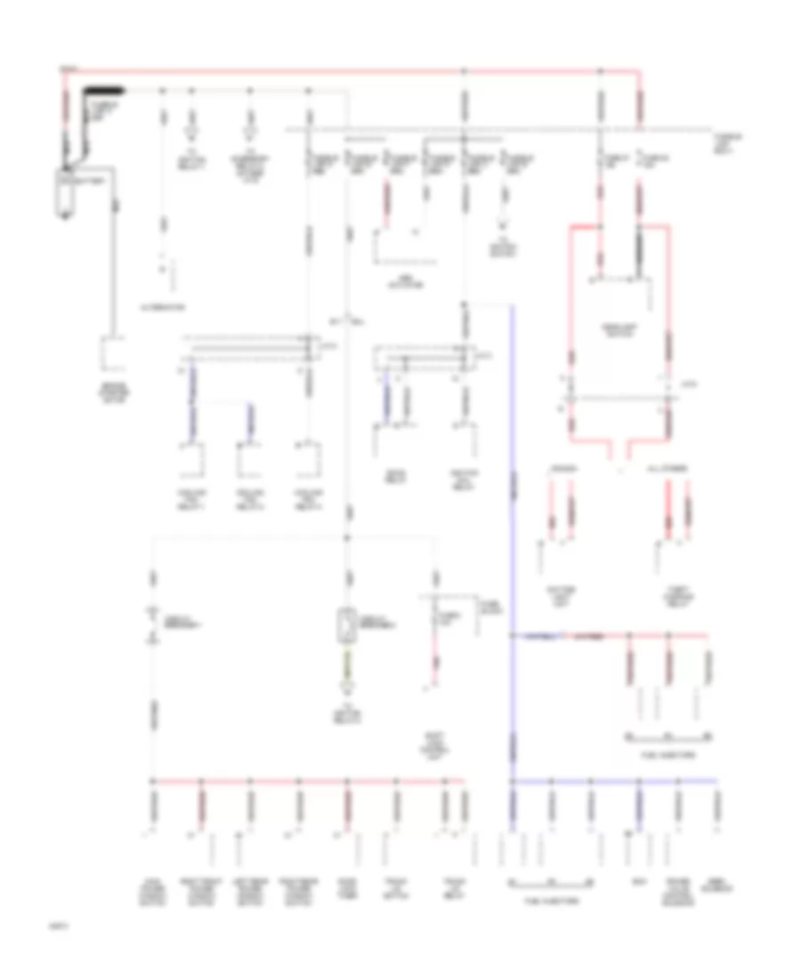
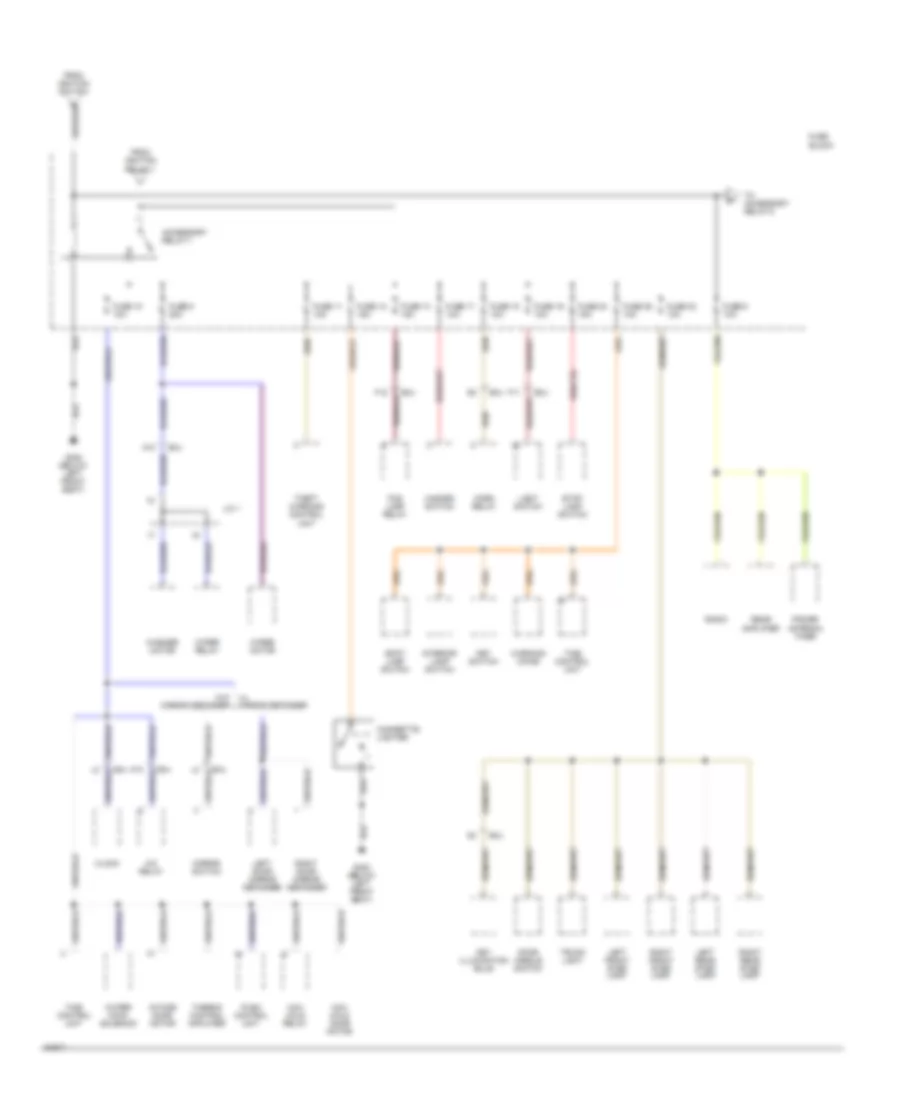
Power Distribution Wiring Diagram (2 of 6) for Nissan Maxima SE 1994
List of elements for Power Distribution Wiring Diagram (2 of 6) for Nissan Maxima SE 1994:
- Abs actuator
- All others
- Alternator
- Battery
- Canada
- Circuit breaker-1
- Circuit breaker-2
- Cooling fan relay-1
- Cooling fan relay-2
- Cooling fan relay-3
- Daytime light unit
- Door lock timer
- E11
- Eccs relay
- Ecm
- Egrc solenoid
- Engine starter motor
- Fuel injectors
- Fuse 2 10a
- Fuse 27 15a
- Fuse 28 15a
- Fuse block
- Fusible link box-1
- Fusible link g red
- Headlight switch
- Ignition coil relay
- Ignition relay-1
- J/c 2
- J/c 3
- J/c 6
- Left rear power window switch
- Main power window switch
- Nca
- Pnk
- Power valve control solenoid
- Red
- Right front power window switch
- Right rear power window switch
- Shift lock control unit
- Smj
- Sohc
- Theft warning relay
- To accessory relay-2, & fuses 14-16
- To ignition relay-2
- To ignition switch
- Trunk lid relay
- Trunk lid switch
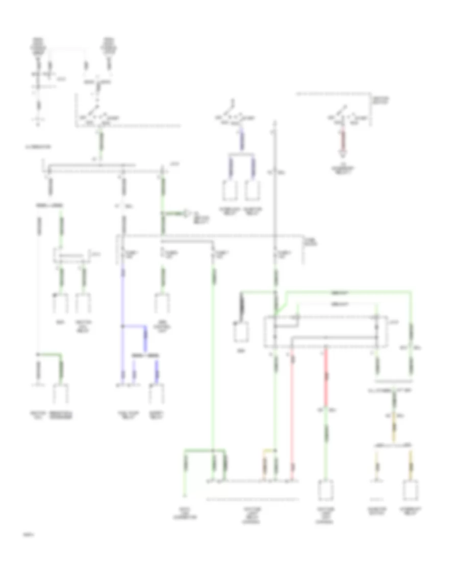
Power Distribution Wiring Diagram (3 of 6) for Nissan Maxima SE 1994
List of elements for Power Distribution Wiring Diagram (3 of 6) for Nissan Maxima SE 1994:
- (canada)
- A/t
- Acc
- All others
- Alternator
- B10
- Data link connector
- Daytime light relay
- Daytime light unit
- Dohc
- Ecm
- From dohc fusible link b
- From sohc fusible link b
- Fuel pump relay
- Fuse 1 15a
- Fuse 3 10a
- Fuse 7 10a
- Fuse 8 10a
- Fuse block
- Ignition coil
- Ignition coil relay
- Ignition switch
- Inhibitor relay
- Inhibitor switch
- Interlock relay
- Interrupt relay
- J/c 2
- J/c 3
- J/c 5
- J/c 9
- M/t
- Off
- Red
- Resistor & condenser
- Run
- Safety relay
- Smj
- Sohc
- Srs control unit
- Start
- To accessory relay-1
- To ignition relay-1
Power Distribution Wiring Diagram (4 of 6) for Nissan Maxima SE 1994
List of elements for Power Distribution Wiring Diagram (4 of 6) for Nissan Maxima SE 1994:
- 25/9
- A/c relay
- A/t
- Abs control unit
- Abs warning lamp
- Ascd hold relay
- Ascd main switch
- Automatic seat belt control
- Close/ up relay
- Combination meter (analog/digital)
- Cooling fan relay-1
- Cooling fan relay-2
- Cooling fan relay-3
- Cornering lamp relay
- Daytime light unit
- Digital touch entry control unit
- Dohc
- Ficd relay
- From circuit breaker-2
- From fusible link a
- From fusible link h
- From ignition switch
- Fuse 20 10a
- Fuse 21 10a
- Fuse 22 10a
- Fuse 26 10a
- Fuse block
- G300 (below left front seat)
- Hazard switch
- Ignition relay-1
- Ignition relay-2
- Inhibitor switch
- Interrupt relay
- J/c 1
- M/t
- Open/ down relay
- Position switch
- Power antenna timer
- Power window main
- Rear window defogger
- Relay
- Shift lock control unit
- Smj
- Sohc
- Switch
- Time control unit
- To accessory relay-1
- Unit
- W/ digital touch entry
- W/o digital touch entry
Power Distribution Wiring Diagram (5 of 6) for Nissan Maxima SE 1994
List of elements for Power Distribution Wiring Diagram (5 of 6) for Nissan Maxima SE 1994:
- A/c relay
- A10
- Accessory relay-1
- Cigarette lighter
- Clock
- Door handle switch
- Fog lamp relay
- From ignition relay-1
- From ignition switch
- Fuse 10 10a
- Fuse 11 10a
- Fuse 12 15a
- Fuse 13 15a
- Fuse 17 10a
- Fuse 18 10a
- Fuse 19 10a
- Fuse 23 10a
- Fuse 24 15a
- Fuse 25 10a
- Fuse 6 20a
- Fuse 9 10a
- Fuse block
- G300 (below left front seat)
- Hazard switch
- Horn relay
- Intake door motor
- Interior lamp switch
- J/c 1
- Key illumination bulb
- Key switch
- Left door mirror defogger
- Left front step lamp
- Left rear step lamp
- Light switch
- Max cold door motor
- Max cold relay
- Mirror switch
- Power antenna timer
- Push control unit
- Radio
- Rear amplifier
- Right door mirror defogger
- Right front step lamp
- Right rear step lamp
- Smj
- Spot lamp switch
- Stop lamp switch
- Theft warning control
- Thermo control amplifier
- Time control unit
- To accessory relay-2
- Trunk light
- Unit
- W/ mirror defogger
- W/o mirror defogger
- Warning chime
- Washer motor
- Water cock solenoid
- Wiper motor
- Wiper relay
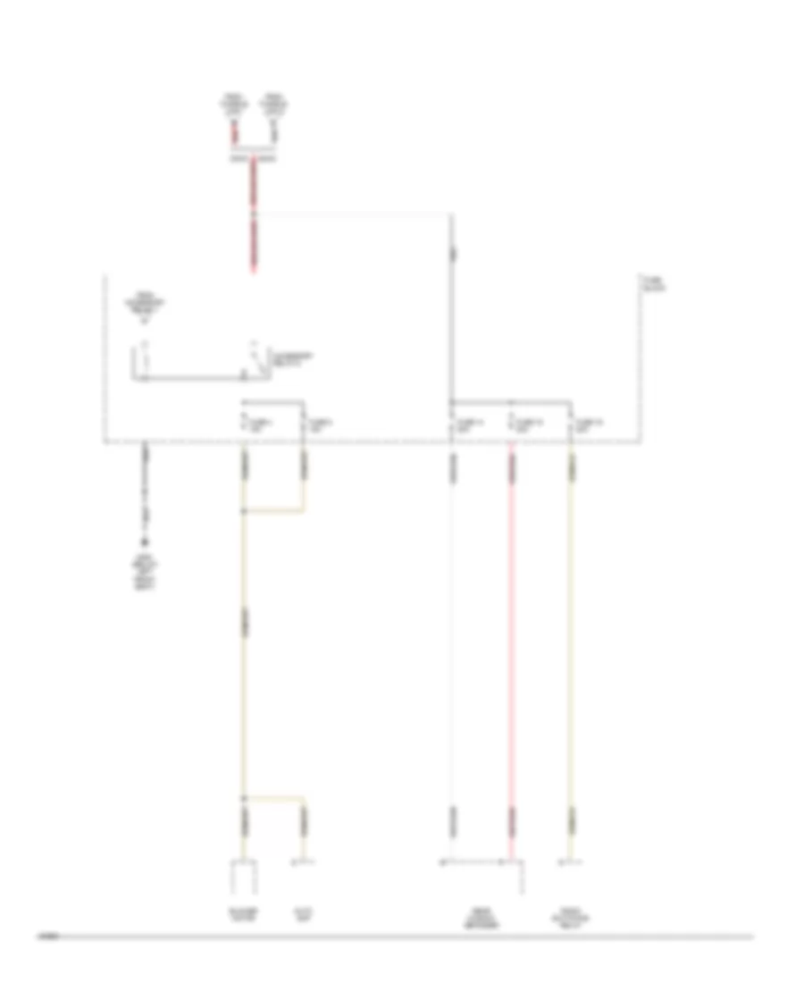
Power Distribution Wiring Diagram (6 of 6) for Nissan Maxima SE 1994
List of elements for Power Distribution Wiring Diagram (6 of 6) for Nissan Maxima SE 1994:
- Accessory relay-2
- Auto amp
- Blower motor
- From accessory relay-1
- From fusible link a
- From fusible link i
- Fuse 14 20a
- Fuse 15 20a
- Fuse 16 20a
- Fuse 4 15a
- Fuse 5 15a
- Fuse block
- G300 (below left front seat)
- Radio switching relay
- Rear window defogger
- Red
- Sohc
POWER DOOR LOCKS
Digital Touch Entry Wiring Diagram (1 of 2) for Nissan Maxima SE 1994
List of elements for Digital Touch Entry Wiring Diagram (1 of 2) for Nissan Maxima SE 1994:
- (below steering column)
- (left i/p,
- (right i/p)
- Above
- Between
- C 1995 vftc
- Circuit breaker-1 (left i/p)
- Digital touch entry control module
- Door lock
- Door lock status
- Fuse 21 10a
- Fuse 23 10a
- Fuse 25 10a
- Fuse block (left i/p)
- Fuse block)
- G201 (right side
- Hot at all times
- Hot in on or start
- Ignition relay-2
- J/c-9
- Key switch
- Left beeper
- Left front door lock actuator
- Left keyboard & led
- Left rear door lock actuator
- Lock
- Locked
- Locked & unlocked
- Of i/p)
- Optional
- Pnk
- Power tops system
- Red
- Right beeper
- Right front door lock actuator
- Right keyboard & led
- Right rear door lock actuator
- Sunroof switch
- Time control unit
- Timer
- Un- lock
- Unlock sensor
- Unlocked
Digital Touch Entry Wiring Diagram (2 of 2) for Nissan Maxima SE 1994
List of elements for Digital Touch Entry Wiring Diagram (2 of 2) for Nissan Maxima SE 1994:
- Between
- C 1995 vftc
- Full stroke
- J/c-8 (left i/p, above fuse block)
- Left door unlock switch
- Left front door switch
- Left lock knob switch
- Left rear door switch
- Lock
- Main switch
- Normal
- Normal & full stroke
- Right door unlock switch
- Right front door switch
- Right front power window switch
- Right lock knob switch
- Right rear door switch
- Theft warning control unit
- Trunk lid opener relay (center rear of trunk)
- Trunk lid opener solenoid (center rear of trunk)
- Trunk lid opener switch
- Unlock
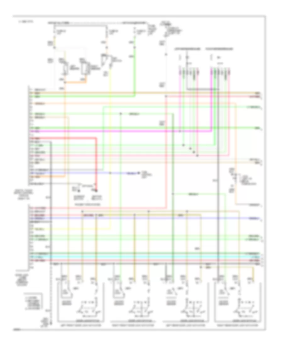
Door Lock Wiring Diagram (1 of 2) for Nissan Maxima SE 1994
List of elements for Door Lock Wiring Diagram (1 of 2) for Nissan Maxima SE 1994:
- (below steering column)
- Between
- C 1995 vftc
- Circuit breaker-1 (left i/p)
- Digital touch entry control unit
- Door lock
- Door lock status
- Fuse 25 10a
- Fuse block (left i/p)
- G201 (right side of i/p)
- Hot at all times
- Key switch
- Left front door lock actuator
- Left rear door lock actuator
- Locked
- Locked & unlocked
- Optional
- Right front door lock actuator
- Right rear door lock actuator
- Time control unit
- Timer
- Unlocked
Door Lock Wiring Diagram (2 of 2) for Nissan Maxima SE 1994
List of elements for Door Lock Wiring Diagram (2 of 2) for Nissan Maxima SE 1994:
- Between
- C 1995 vftc
- Digital touch entry control unit
- Full stroke
- Illumunation
- Interior lights system (rheostat)
- J/c-8 (left i/p, above fuse block)
- Left door unlock switch
- Left front door switch
- Left lock knob switch
- Lock
- Main switch
- Normal
- Normal & full stroke
- Optional
- Right door unlock switch
- Right front door switch
- Right lock knob switch
- Theft warning control unit
- Unlock
POWER MIRRORS
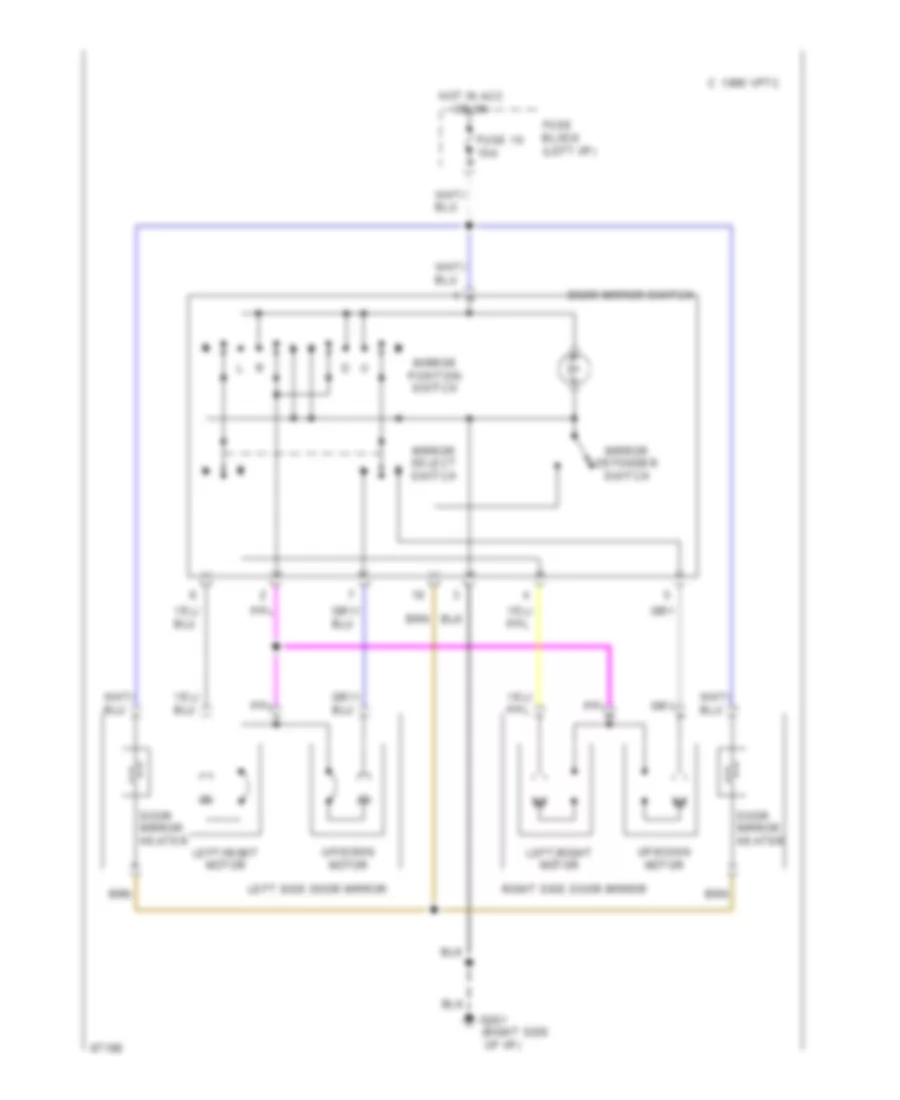
Power Mirror Wiring Diagram for Nissan Maxima SE 1994
List of elements for Power Mirror Wiring Diagram for Nissan Maxima SE 1994:
- (right side
- C 1995 vftc
- Door mirror heater
- Door mirror switch
- Fuse 10 10a
- Fuse block (left i/p)
- G201
- Hot in acc or on
- Left side door mirror
- Left/right motor
- Mirror defogger switch
- Mirror position switch
- Mirror select switch
- Of i/p)
- Right side door mirror
- Up/down motor
POWER SEATS
Power Seats Wiring Diagram for Nissan Maxima SE 1994
List of elements for Power Seats Wiring Diagram for Nissan Maxima SE 1994:
- 1 fully rearward
- 2 fully forward
- Circuit breaker-1 (left i/p)
- Driver's seat
- Driver's seat switch
- Hot at all times
- Limit switch
- Passenger's seat
- Passenger's seat switch
- Recline
- Red
- Seat reclining motor
- Seat sliding motor
- Slide
POWER TOP/SUNROOF
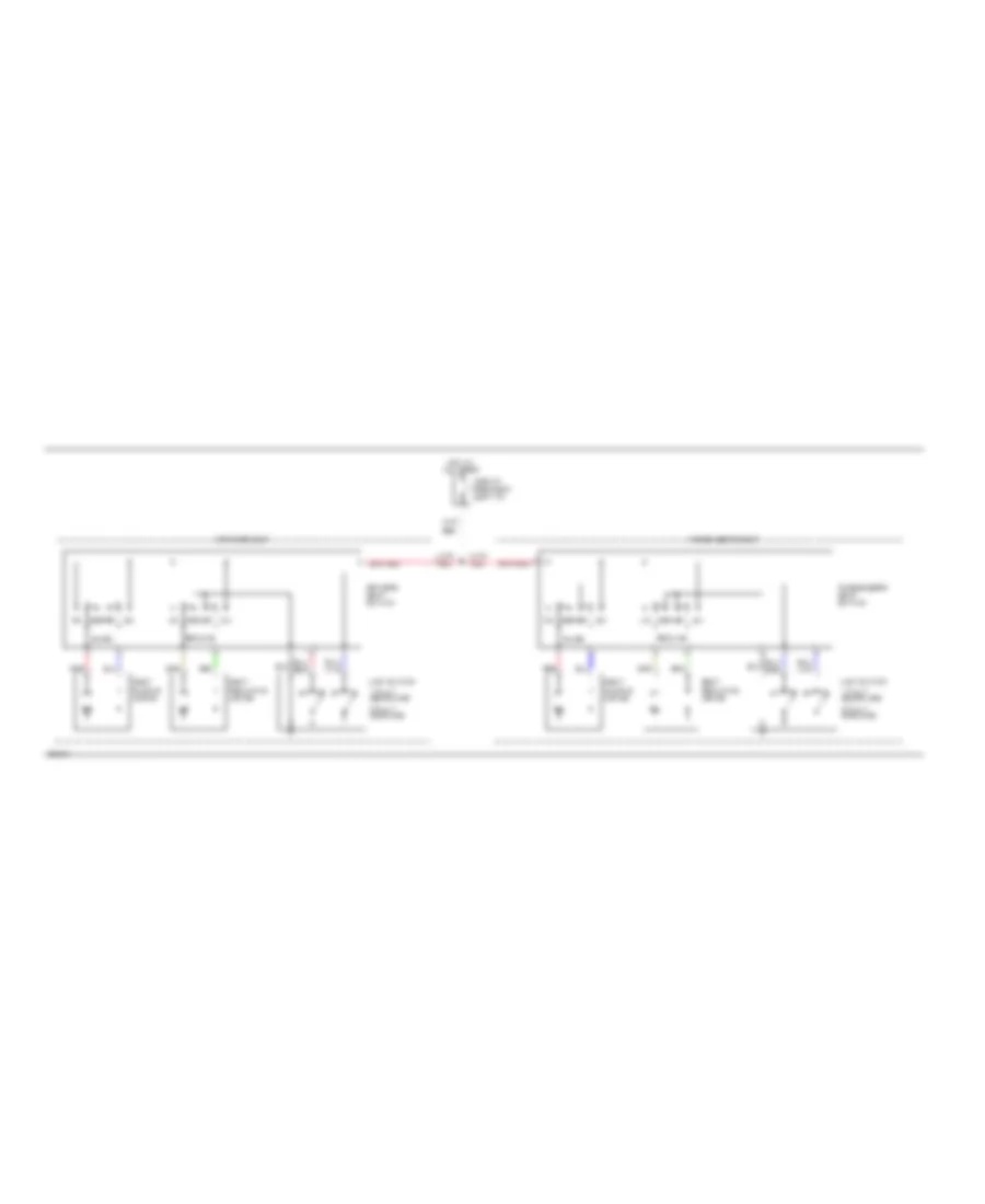
Power Top/Sunroof Wiring Diagrams, with Remote/Keyless Entry for Nissan Maxima SE 1994
List of elements for Power Top/Sunroof Wiring Diagrams, with Remote/Keyless Entry for Nissan Maxima SE 1994:
- Circuit breaker 2 (left side of i/p)
- Close/ up
- Close/up relay (left front of roof)
- Digital touch entry control unit (right side kick panel)
- Fuse 21 10a
- Fuse block (left side of i/p)
- G201 (right side of i/p)
- G904 (left side "c" pillar)
- Hot at all times
- Hot in run or start
- Ignition relay 2 (left kick panel)
- Open/ down
- Open/down relay (center front of roof)
- Red
- Sunroof motor assembly (center front of roof)
- Sunroof switch
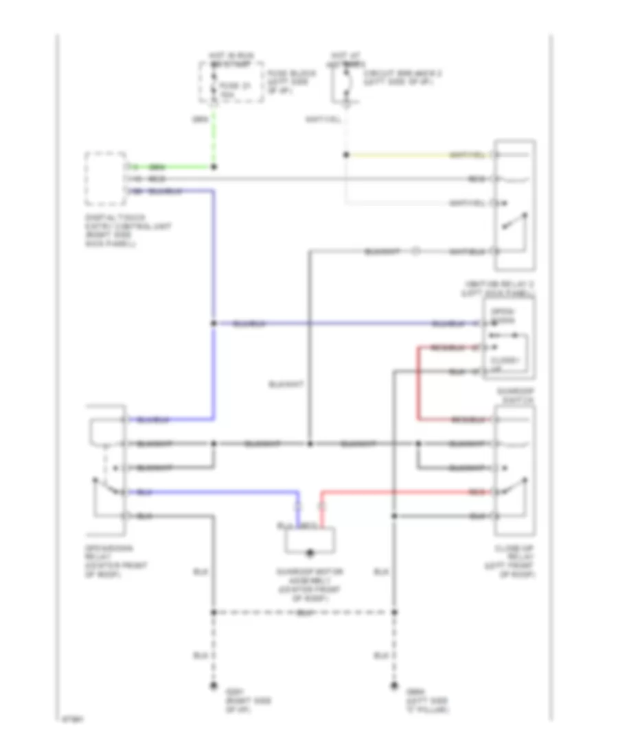
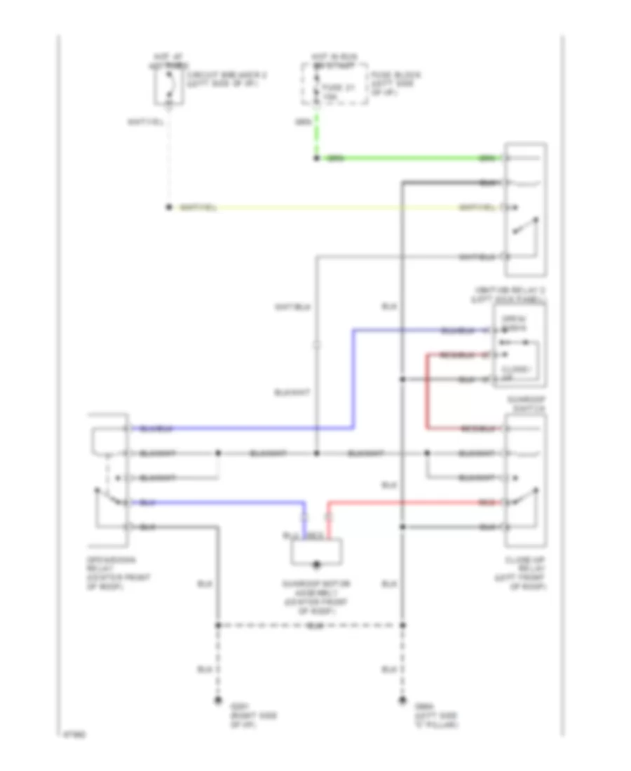
Power Top/Sunroof Wiring Diagrams, without Remote/Keyless Entry for Nissan Maxima SE 1994
List of elements for Power Top/Sunroof Wiring Diagrams, without Remote/Keyless Entry for Nissan Maxima SE 1994:
- Circuit breaker 2 (left side of i/p)
- Close/ up
- Close/up relay (left front of roof)
- Fuse 21 10a
- Fuse block (left side of i/p)
- G201 (right side of i/p)
- G904 (left side "c" pillar)
- Hot at all times
- Hot in run or start
- Ignition relay 2 (left kick panel)
- Open/ down
- Open/down relay (center front of roof)
- Red
- Sunroof motor assembly (center front of roof)
- Sunroof switch
POWER WINDOWS
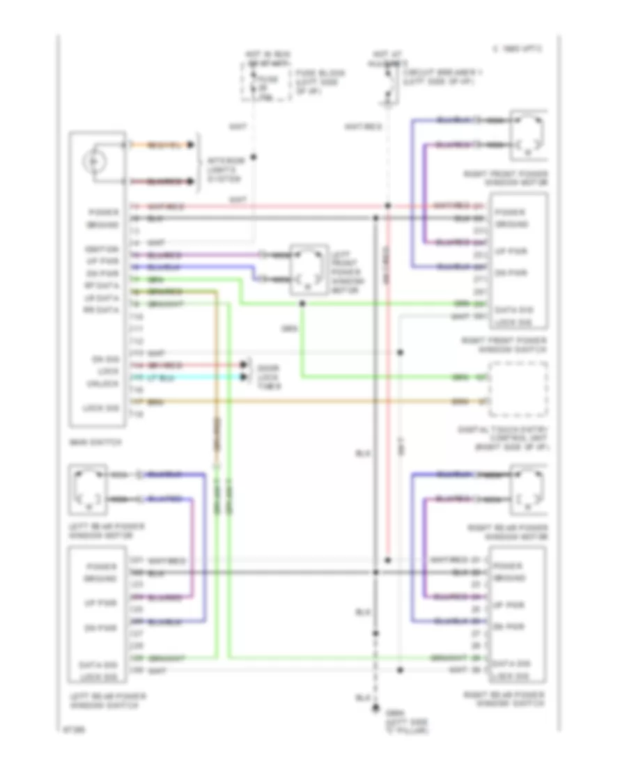
Power Window Wiring Diagram for Nissan Maxima SE 1994
List of elements for Power Window Wiring Diagram for Nissan Maxima SE 1994:
- 1995 vftc c
- Circuit breaker 1 (left side of i/p)
- Data sig
- Digital touch entry control unit (right side of i/p)
- Dn pwr
- Dn sig
- Door lock timer
- Fuse 10a
- Fuse block (left side of i/p)
- G904 (left side "c" pillar)
- Ground
- Hot at all times
- Hot in run or start
- Ignition
- Interior lights system
- Left front power window motor
- Left rear power window motor
- Left rear power window switch
- Lock
- Lock sig
- Lr data
- Main switch
- Nca
- Power
- Rf data
- Right front power window motor
- Right front power window switch
- Right rear power window motor
- Right rear power window switch
- Rr data
- Unlock
- Up pwr
RADIO
Base Radio for Nissan Maxima SE 1994
List of elements for Base Radio for Nissan Maxima SE 1994:
- (right side of dash) g201
- Fuse 10a
- Hot at all times
- Hot in acc or on
- Interior lights system
- Left front speaker
- Left rear speaker
- Nca
- Passenger compartment fuse/relay block (under left side of dash)
- Power antenna system
- Radio
- Rear amplifier (on underside of rear shelf, in trunk)
- Right front speaker
- Right rear speaker
- Rod antenna
- Window antenna
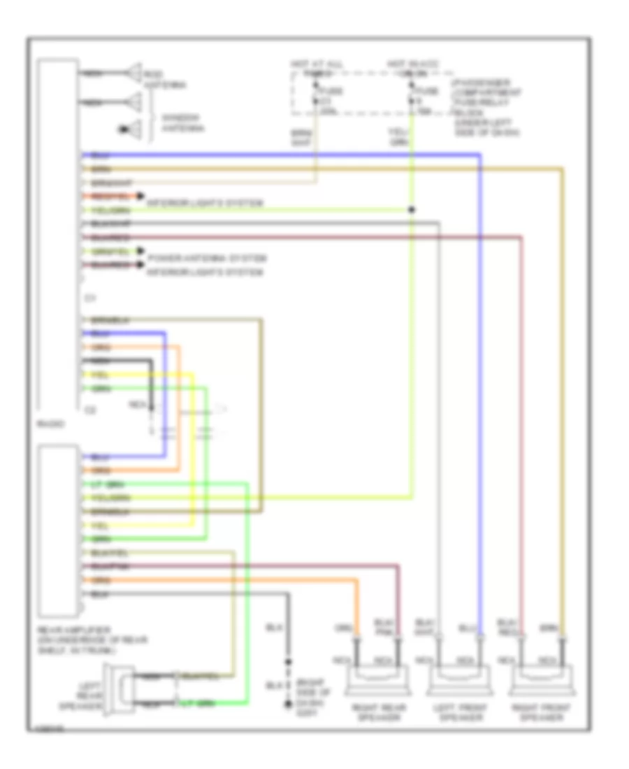
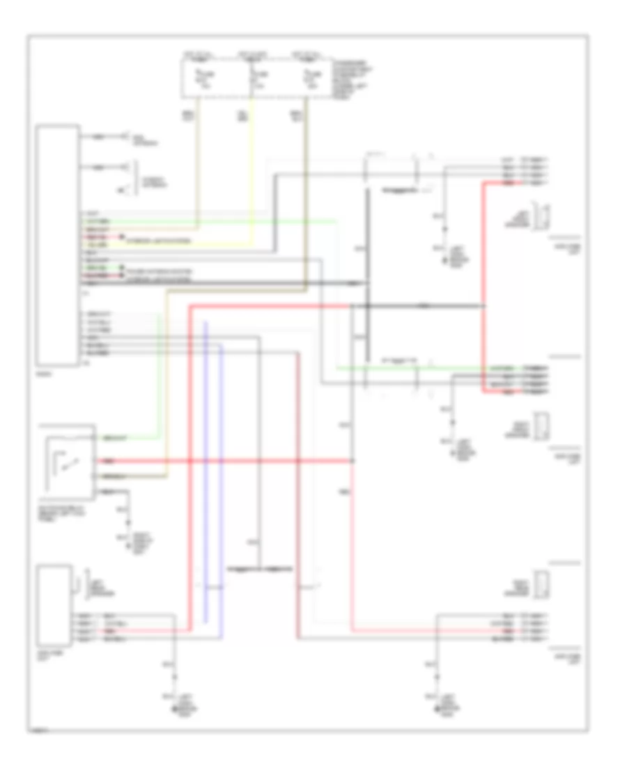
Premium Sound Radio Wiring Diagram for Nissan Maxima SE 1994
List of elements for Premium Sound Radio Wiring Diagram for Nissan Maxima SE 1994:
- (left dash brace) g206
- (right side of dash) g201
- Amplifier unit
- Fuse 10a
- Fuse 20a
- Hot at all times
- Hot in acc or on
- Interior lights system
- Left front speaker
- Left rear speaker
- Nca
- Passenger compartment fuse/relay block (under left side of dash)
- Power antenna system
- Radio
- Red
- Right front speaker
- Right rear speaker
- Rod antenna
- Switching relay (behind left kick panel)
- Window antenna
SHIFT INTERLOCKS
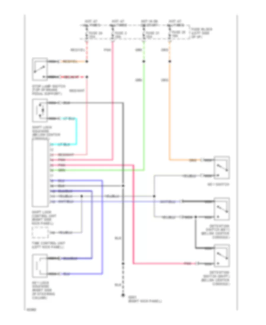
Shift Interlock Wiring Diagram for Nissan Maxima SE 1994
List of elements for Shift Interlock Wiring Diagram for Nissan Maxima SE 1994:
- Detention switch (key) (below center console)
- Detention switch (shift) (below center console)
- Fuse 2 10a
- Fuse 21 10a
- Fuse 24 15a
- Fuse 25 10a
- Fuse block (left side of i/p)
- G203 (right kick panel)
- Hot at all times
- Hot in on or start
- Key lock solenoid (right side of steering column)
- Key switch
- Nca
- Pnk
- Shift lock control unit (right side kick panel)
- Shift lock solenoid (below center console)
- Stop lamp switch (top of brake pedal support)
- Time control unit (left kick panel)
STARTING/CHARGING
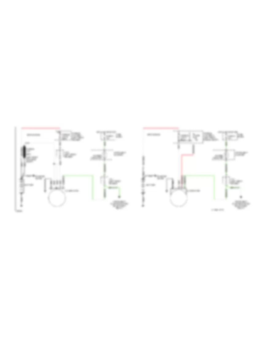
Charging Wiring Diagram for Nissan Maxima SE 1994
List of elements for Charging Wiring Diagram for Nissan Maxima SE 1994:
- (left front of engine compt)
- 1994 vftc c
- Alternator
- Battery
- Charge indicator
- Dohc engine
- Fuse 10a
- Fuse 21 10a
- Fuse block
- Fusible link
- Fusible link box 1 (left front fender)
- Fusible link box 2 (left front engine compt)
- Hot in on or start
- Instrument cluster
- Instrument cluster system (bulb check relay)
- J/c 1 (left front fender)
- J/c 2 (left front fender)
- Nca
- Sohc engine
- Starter motor
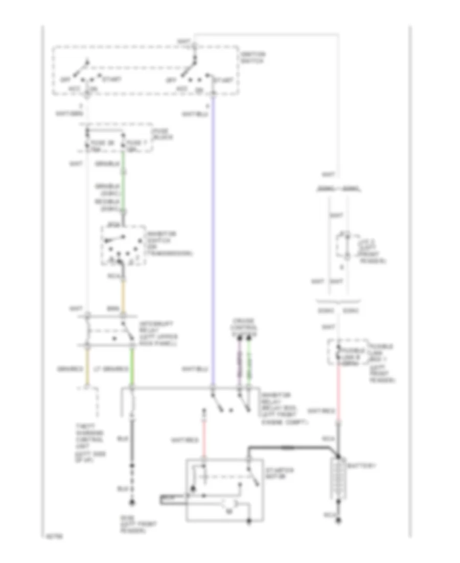
Starting Wiring Diagram, A/T for Nissan Maxima SE 1994
List of elements for Starting Wiring Diagram, A/T for Nissan Maxima SE 1994:
- (dohc)
- (left front fender)
- (left side of i/p)
- (sohc)
- Acc
- Battery
- Cruise control system
- Dohc
- Engine compt)
- Fuse 26 10a
- Fuse 7 10a
- Fuse block
- Fusible link box 1
- G100 (left front fender)
- Ignition switch
- Inhibitor relay (relay box, left front
- Inhibitor switch (on transmission)
- Interrupt relay (left upper kick panel)
- J/c 2 (left front fender)
- Nca
- Off
- Sohc
- Start
- Starter motor
- Theft warning control unit
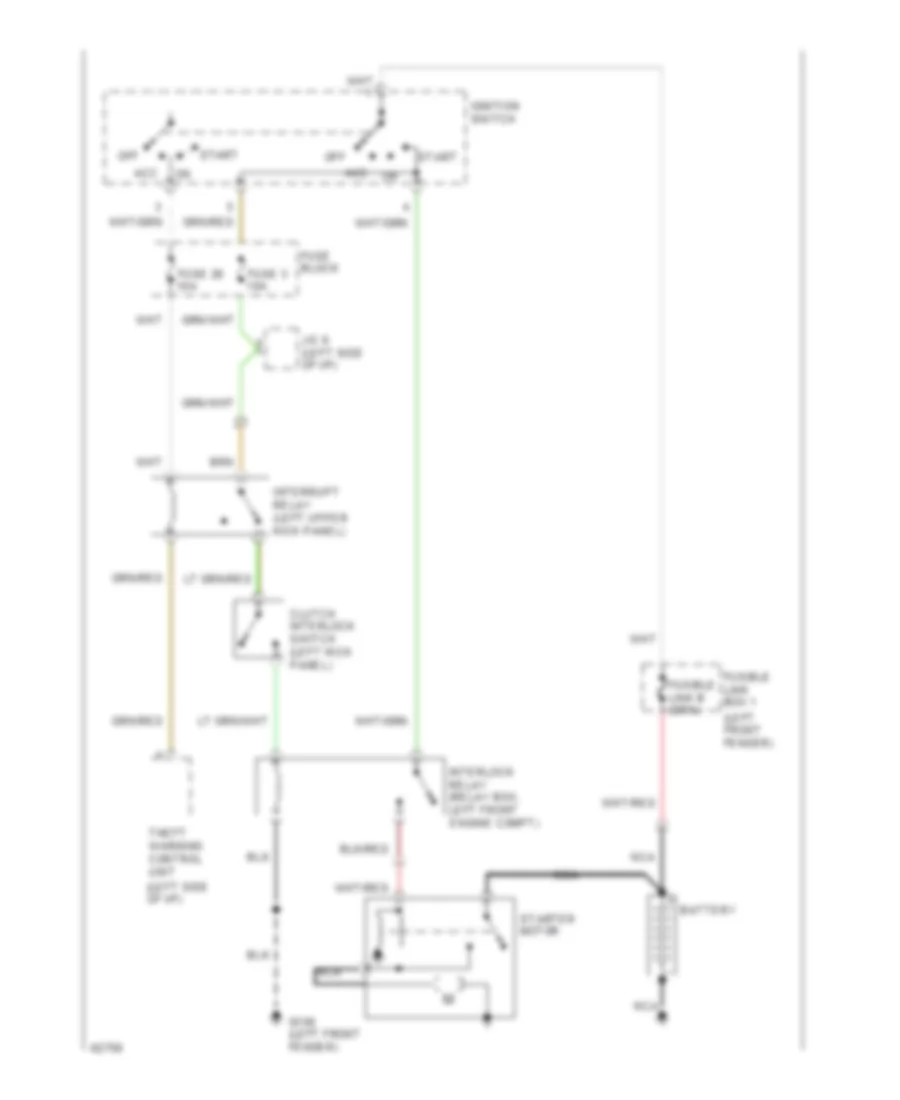
Starting Wiring Diagram, M/T for Nissan Maxima SE 1994
List of elements for Starting Wiring Diagram, M/T for Nissan Maxima SE 1994:
- (left front fender)
- (left side of i/p)
- Acc
- Battery
- Clutch interlock switch (left kick panel)
- Fuse 26 10a
- Fuse 3 10a
- Fuse block
- Fusible link box 1
- G100 (left front fender)
- Ignition switch
- Interlock relay (relay box, left front engine compt)
- Interrupt relay (left upper kick panel)
- J/c 9 (left side of i/p)
- Nca
- Off
- Start
- Starter motor
- Theft warning control unit
SUPPLEMENTAL RESTRAINTS
Supplemental Restraint Wiring Diagram for Nissan Maxima SE 1994
List of elements for Supplemental Restraint Wiring Diagram for Nissan Maxima SE 1994:
- 1 digital cluster
- 2 standard cluster
- Air bag control unit (below center of i/p)
- Air bag ind.
- Airbag module (top of steering column)
- Cluster
- Data link connector for consult (left side of i/p)
- Front crash zone sensor (center front of radiator)
- Fuse 21 10a
- Fuse 23 10a
- Fuse 8 10a
- Fuse block (left side of i/p)
- G201 (right side of i/p)
- G206 (center of i/p)
- Hot at all times
- Hot in on or start
- Instrument
- Left front door switch
- Nca
- Red
- Spiral cable
- Tunnel and safing sensor (below center console)
TRANSMISSION
3.0L
3.0L DOHC, Transmission Wiring Diagram, Analog Cluster for Nissan Maxima SE 1994
List of elements for 3.0L DOHC, Transmission Wiring Diagram, Analog Cluster for Nissan Maxima SE 1994:
- (right side of i/p) g201
- A/t control unit (behind center console, front of gear selector)
- A/t fluid temp. sensor
- A/t mode switch
- All times
- Ascd control unit (right of steering column)
- Auto
- Automatic transaxle
- Backup lights
- Closed throttle
- Cmfrt
- Comfort ind.
- Cruise
- Data link connector (for consult) (below left side of i/p)
- Dropping resistor (below air cleaner assembly)
- Eccs control module (behind center console)
- Engine coolant temperature sensor (top of water inlet housing)
- Fuse 10a
- Fuse block (left kick panel)
- G125 (center front of engine)
- G200 (left kick panel)
- Hot at
- Hot in on or start
- Ill.
- Ind.
- Inhibitor switch (right transaxle)
- Instrument cluster
- Interior lights system
- Line press. sol. valve
- Nca
- O.d. off ind.
- Overdrive switch
- Power ind.
- Pwr
- Red
- Revolution sensor
- Shift sol. valve a
- Shift sol. valve b
- Speedometer
- Tachometer
- Tcc sol. valve
- Throttle position sensor (on throttle body)
- Throttle position switch (on throttle body)
- Timing sol. valve
- Vehicle speed sensor
- W/ air bag
- W/o air bag
- Wot
3.0L DOHC, Transmission Wiring Diagram, Digital Cluster for Nissan Maxima SE 1994
List of elements for 3.0L DOHC, Transmission Wiring Diagram, Digital Cluster for Nissan Maxima SE 1994:
- (right side of i/p) g201
- A/t control unit (behind center console, front of gear selector)
- A/t fluid temp. sensor
- A/t mode switch
- All times
- Ascd control unit (right of steering column)
- Auto
- Automatic transaxle
- Backup lights
- Closed throttle
- Cluster
- Cmfrt
- Comfort ind.
- Control unit
- Cruise
- Data link connector (for consult) (below left side of i/p)
- Dropping resistor (below air cleaner assembly)
- Eccs control module (behind center console)
- Engine coolant temperature sensor (top of water inlet housing)
- Fuse 10a
- Fuse block (left kick panel)
- G125 (center front of engine)
- G200 (left kick panel)
- Hot at
- Hot in on or acc
- Hot in on or start
- Ill.
- Ind.
- Inhibitor switch (right transaxle)
- Instrument c1
- Interior lights system
- Line press. sol. valve
- Nca
- O.d. off ind.
- Overdrive switch
- Power ind.
- Pwr
- Red
- Revolution sensor
- Shift sol. valve a
- Shift sol. valve b
- Speedo- meter
- Tachometer
- Tcc sol. valve
- Throttle position sensor (on throttle body)
- Throttle position switch (on throttle body)
- Timing sol. valve
- Vehicle speed sensor
- W/ air bag
- W/o air bag
- Wot
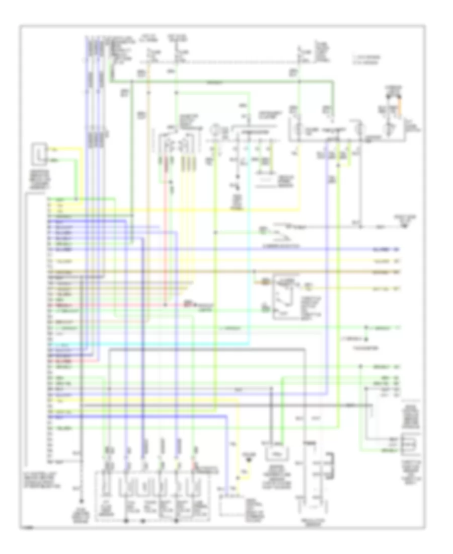
3.0L SOHC, Transmission Wiring Diagram for Nissan Maxima SE 1994
List of elements for 3.0L SOHC, Transmission Wiring Diagram for Nissan Maxima SE 1994:
- (right side of i/p) g201
- A/t control unit (behind center console, front of gear selector)
- A/t fluid temp. sensor
- A/t mode switch
- All times
- Ascd control unit (right of steering column)
- Auto
- Automatic transaxle
- Backup lights
- Closed throttle
- Cmfrt
- Comfort ind.
- Cruise
- Data link connector (for consult) (below left side of i/p)
- Dropping resistor (below air cleaner assembly)
- Eccs control module (behind center console)
- Engine coolant temperature sensor (top of water inlet housing)
- Fuse 10a
- Fuse block (left kick panel)
- G125 (center front of engine)
- G200 (left kick panel)
- Hot at
- Hot in on or start
- Ill.
- Ind.
- Inhibitor switch (right transaxle)
- Instrument cluster
- Interior lights system
- Line press. sol. valve
- Nca
- Not used
- O.d. off ind.
- Over- run clutch sol. valve
- Overdrive switch
- Pnk
- Power ind.
- Pwr
- Red
- Revolution sensor
- Shift sol. valve a
- Shift sol. valve b
- Speedometer
- Tachometer
- Tcc sol. valve
- Throttle position sensor (on throttle body)
- Throttle position switch (on throttle body)
- Vehicle speed sensor
- W/ air bag
- W/o air bag
- Wot
TRUNK, TAILGATE, FUEL DOOR
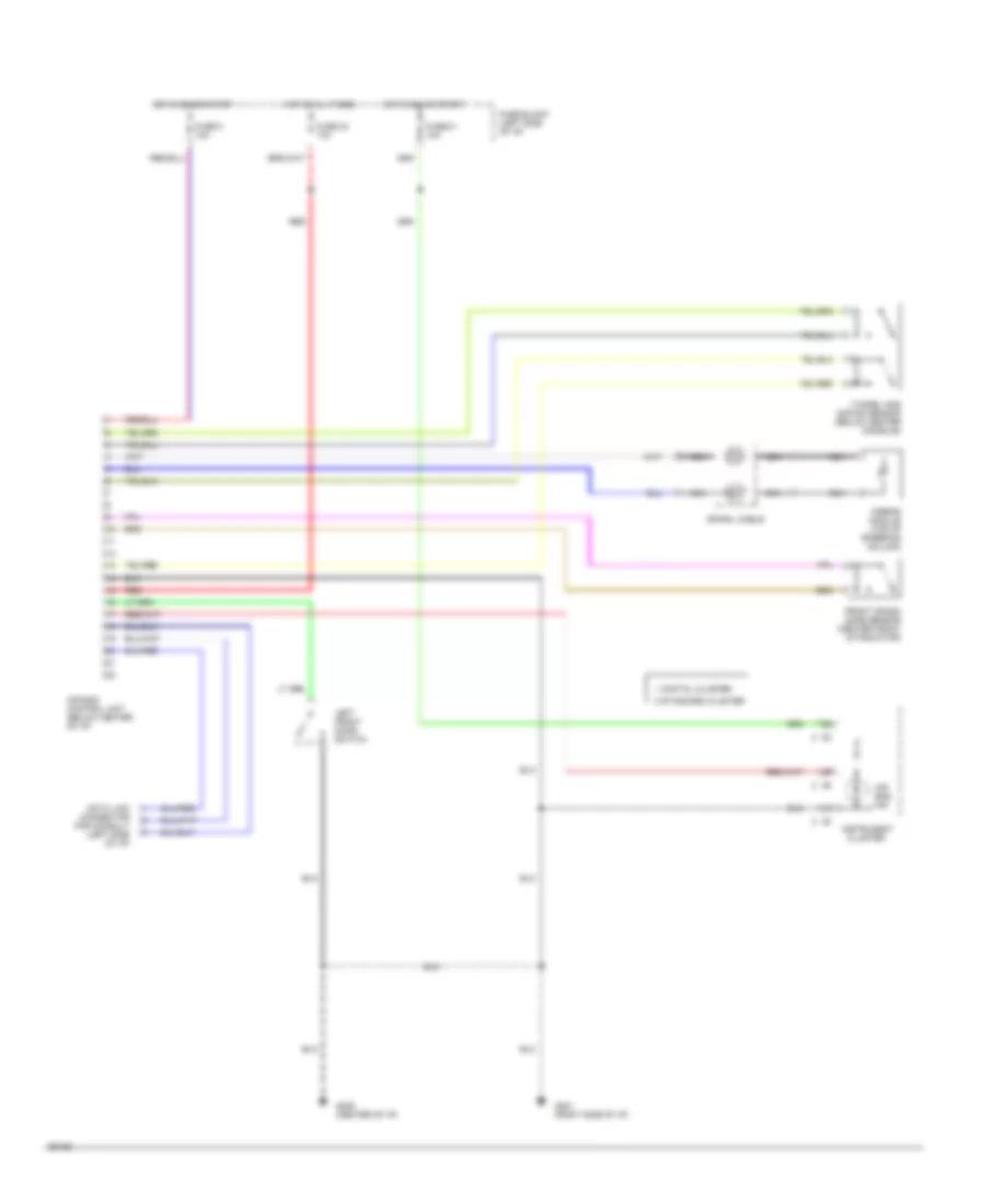
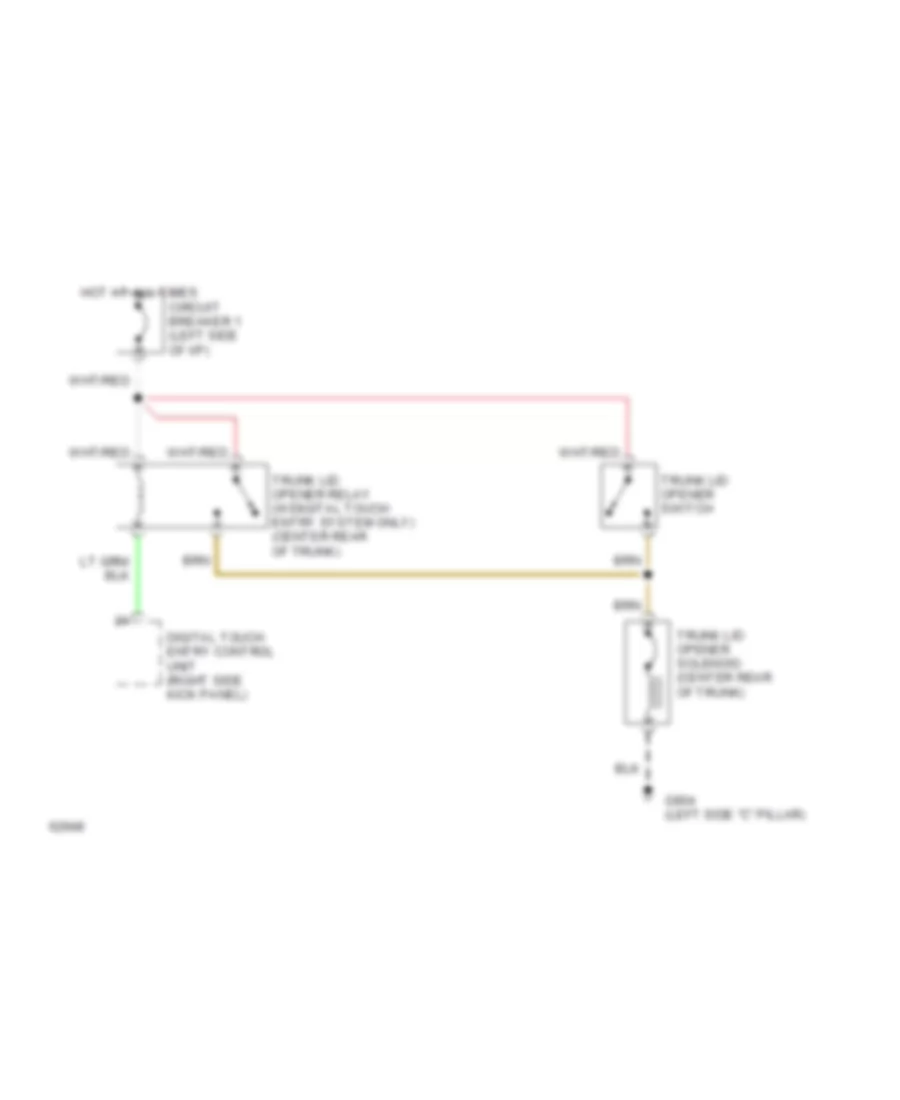
Trunk Release Wiring Diagram for Nissan Maxima SE 1994
List of elements for Trunk Release Wiring Diagram for Nissan Maxima SE 1994:
- Circuit breaker 1 (left side of i/p)
- Digital touch entry control unit (right side kick panel)
- G904 (left side "c" pillar)
- Hot at all times
- Trunk lid opener relay (w/digital touch entry system only) (center rear of trunk)
- Trunk lid opener solenoid (center rear of trunk)
- Trunk lid opener switch
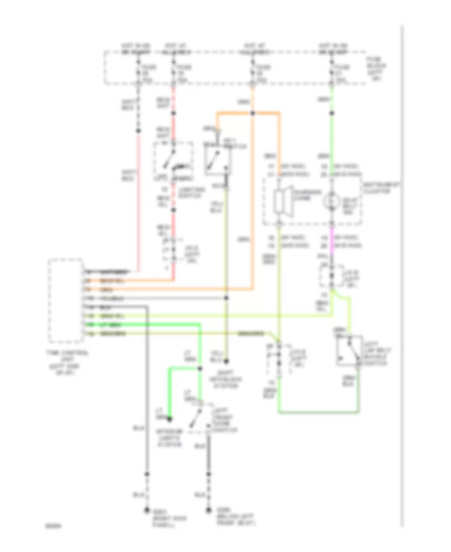
WARNING SYSTEMS
Warning System Wiring Diagrams, Canada for Nissan Maxima SE 1994
List of elements for Warning System Wiring Diagrams, Canada for Nissan Maxima SE 1994:
- (below left front seat)
- (left side of i/p)
- (w/ hud)
- (w/o hud)
- Block (left i/p)
- Fuse
- Fuse 10a
- G203 (right kick panel)
- G300
- Head
- Hot at all times
- Hot in on or start
- Instrument cluster
- Interior lights system
- J/c-5 (left i/p)
- J/c-8 (left i/p)
- J/c-9 (left i/p)
- Key switch
- Left front door switch
- Left lap belt buckle switch
- Lighting switch
- Nca
- Off
- Park
- Seat belt ind.
- Shift interlock system
- Time control unit
- Warning chime
Warning System Wiring Diagrams, USA for Nissan Maxima SE 1994
List of elements for Warning System Wiring Diagrams, USA for Nissan Maxima SE 1994:
- (below left front seat)
- (left side of i/p)
- (w/ hud)
- (w/o hud)
- Automatic seat belt control unit (behind glove box)
- Block (left i/p)
- Fuse
- Fuse 10a
- G203 (right kick panel)
- G300
- Head
- Hot at all times
- Hot in on or start
- Instrument cluster
- Interior lights system
- J/c-5 (left i/p)
- J/c-8 (left i/p)
- Key switch
- Left front door switch
- Left lap belt buckle switch
- Lighting switch
- Nca
- Off
- Park
- Seat belt ind.
- Shift interlock system
- Time control unit
- Warning chime
WIPER/WASHER
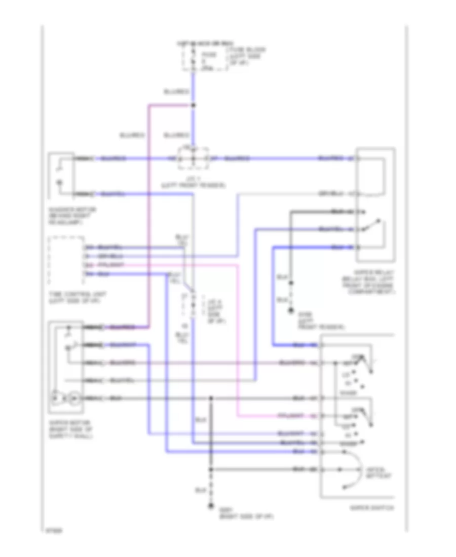
Wiper/Washer Wiring Diagram for Nissan Maxima SE 1994
List of elements for Wiper/Washer Wiring Diagram for Nissan Maxima SE 1994:
- Fuse 20a
- Fuse block (left side of i/p)
- G100 (left front fender)
- G201 (right side of i/p)
- Hot in acc or run
- Int
- Inter- mittent
- J/c 1 (left front fender)
- J/c 4 (left side of i/p)
- Nca
- Off
- Time control unit (left side of i/p)
- Wash
- Washer motor (behind right headlamp)
- Wiper motor (right side of safety wall)
- Wiper relay (relay box, left front of engine compartment)
- Wiper switch

 Čeština
 Dansk
Dansk Deutsch
 Ελληνικά
 English
 English
 Español
 Suomi
Suomi Français
 עברית
עברית Hrvatski
 Magyar
 Italiano
 日本語
日本語 한국어
한국어 Nederlands
 Polski
 Português
 Português
 Română
 Русский
 Slovenčina
 Slovenščina
 Svenska
 Türkçe
 中文 (中国)