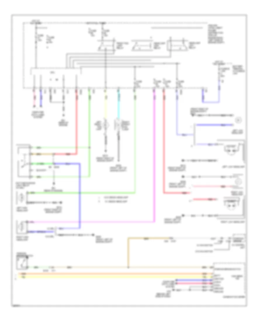
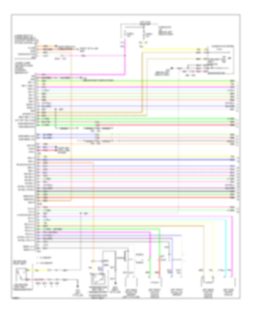
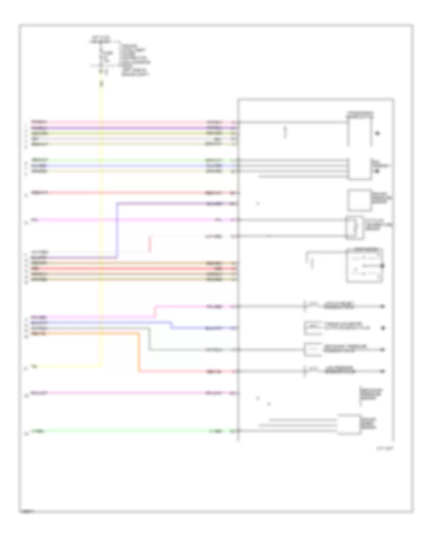
AIR CONDITIONING
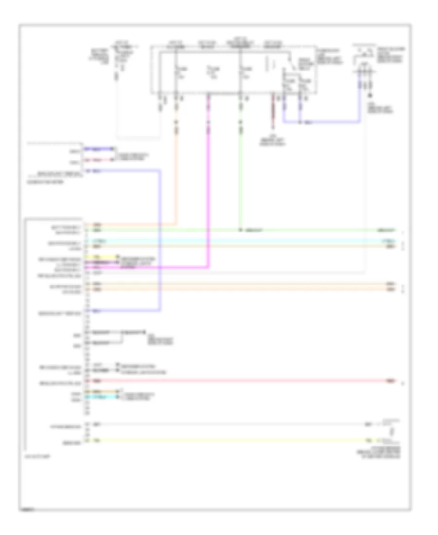
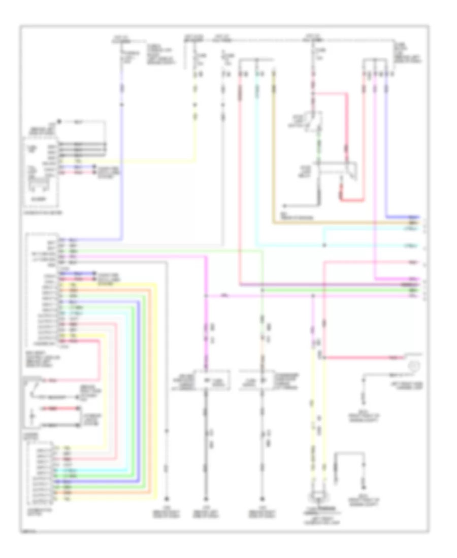
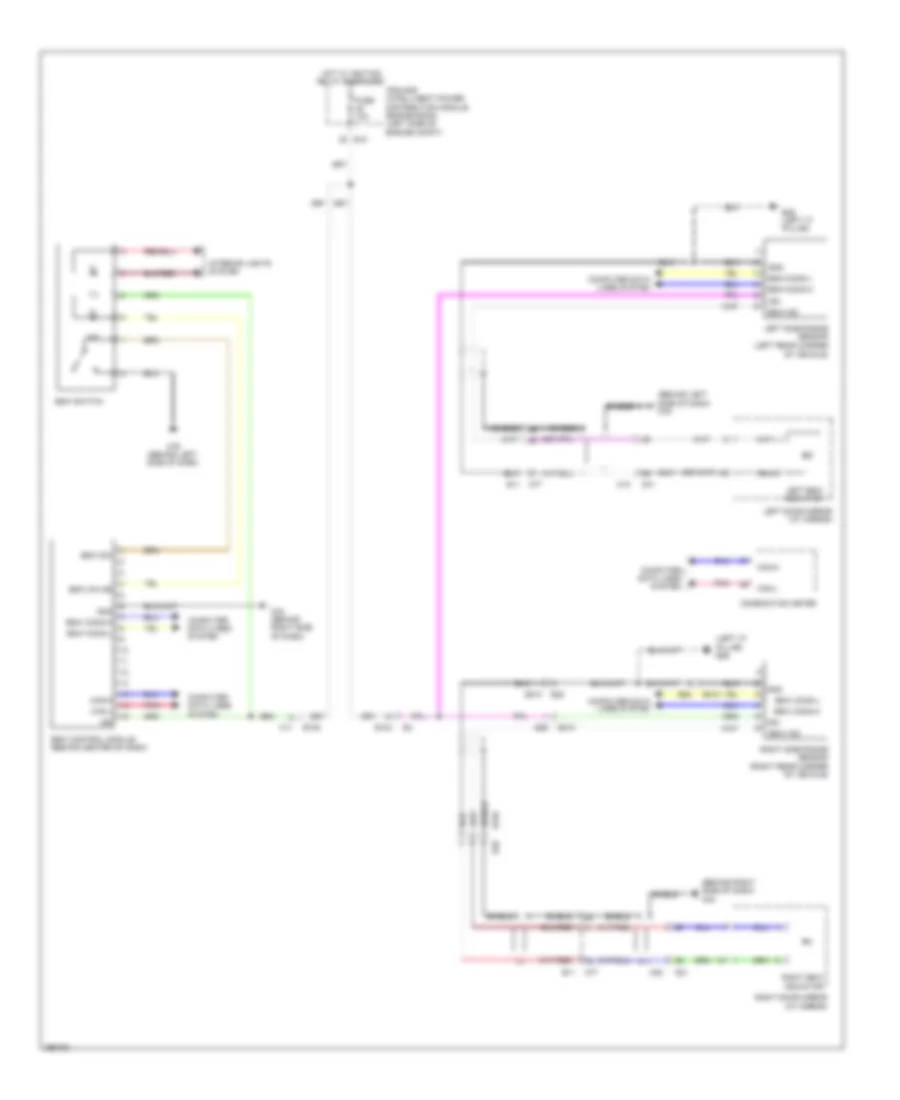
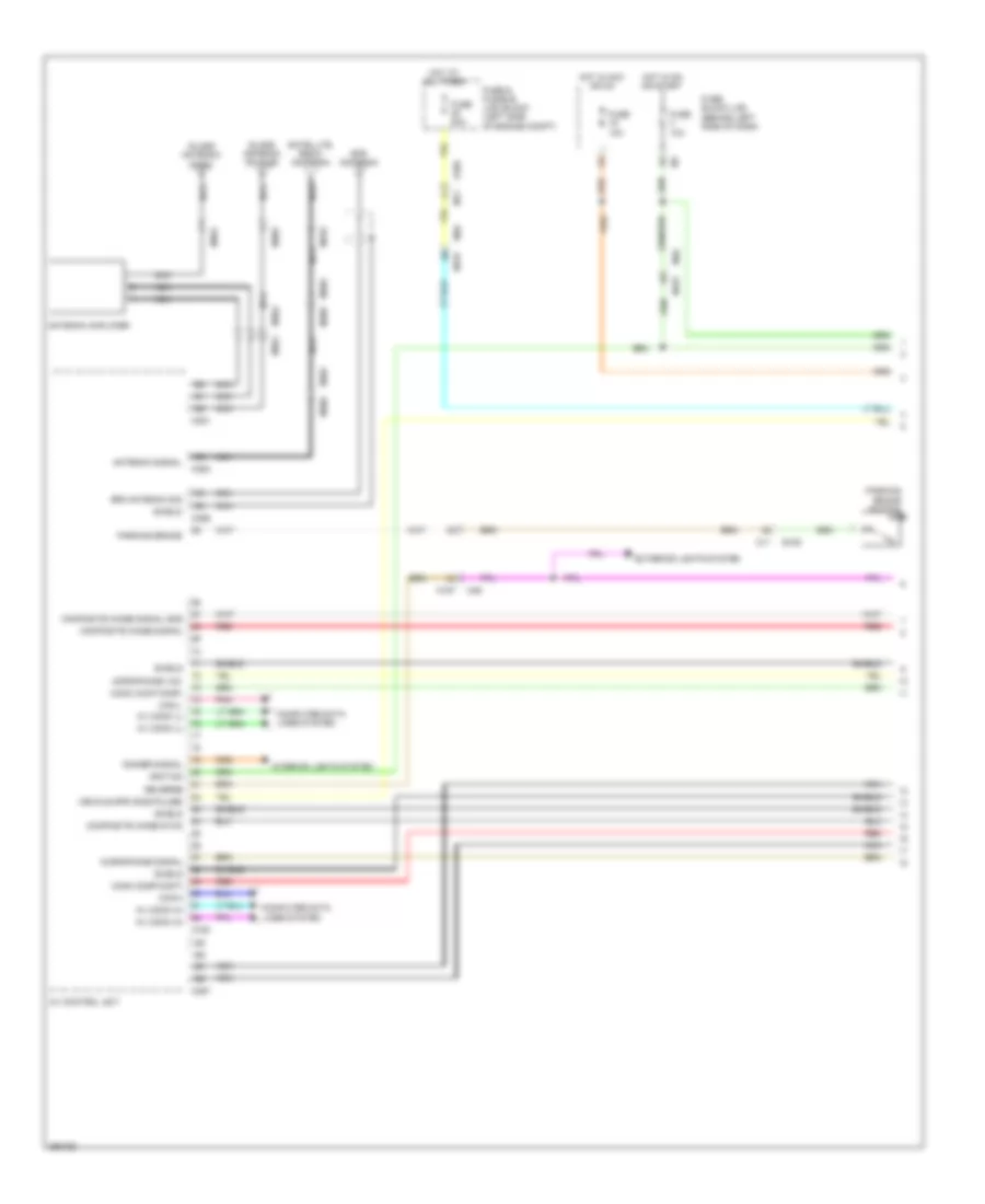
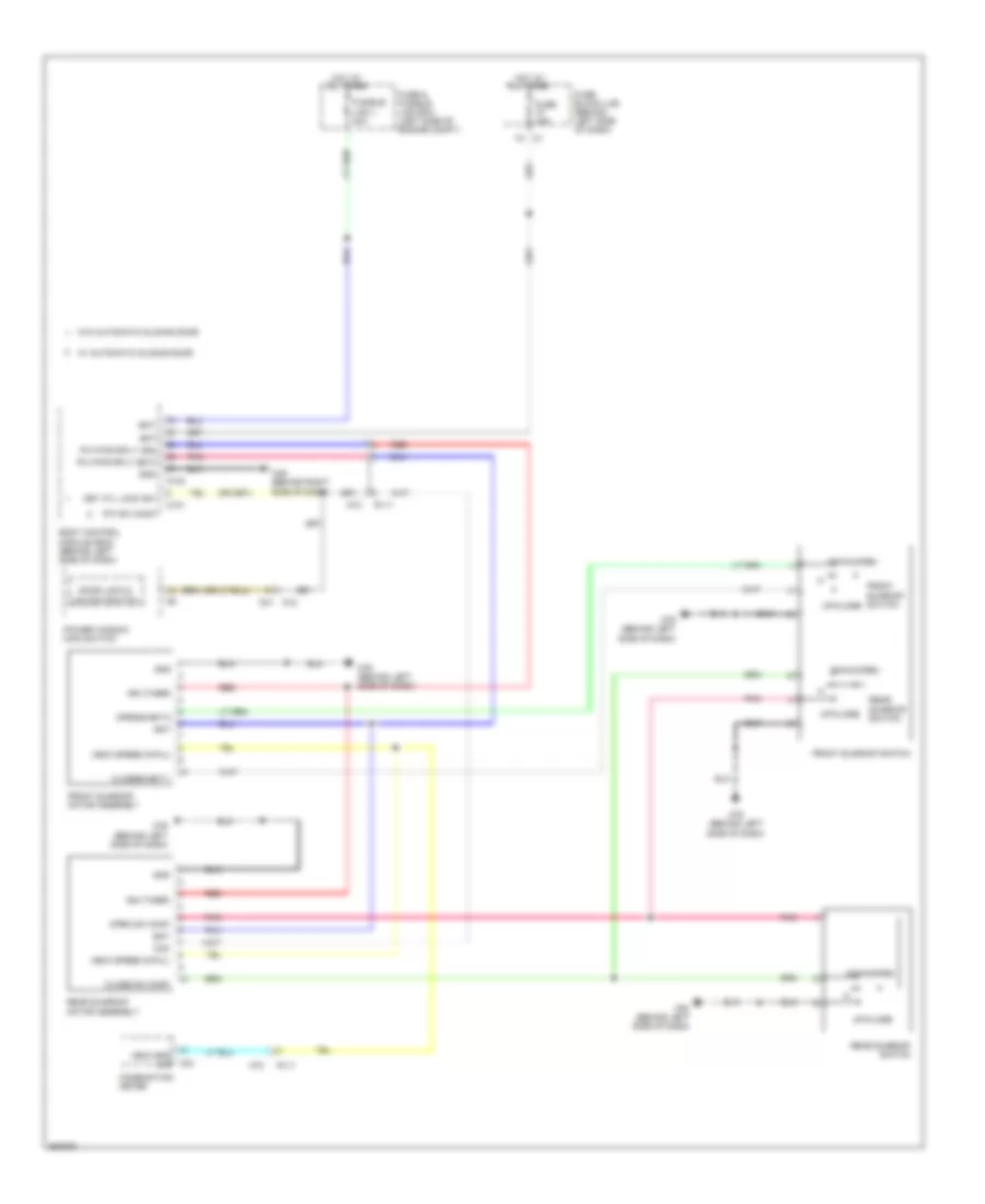
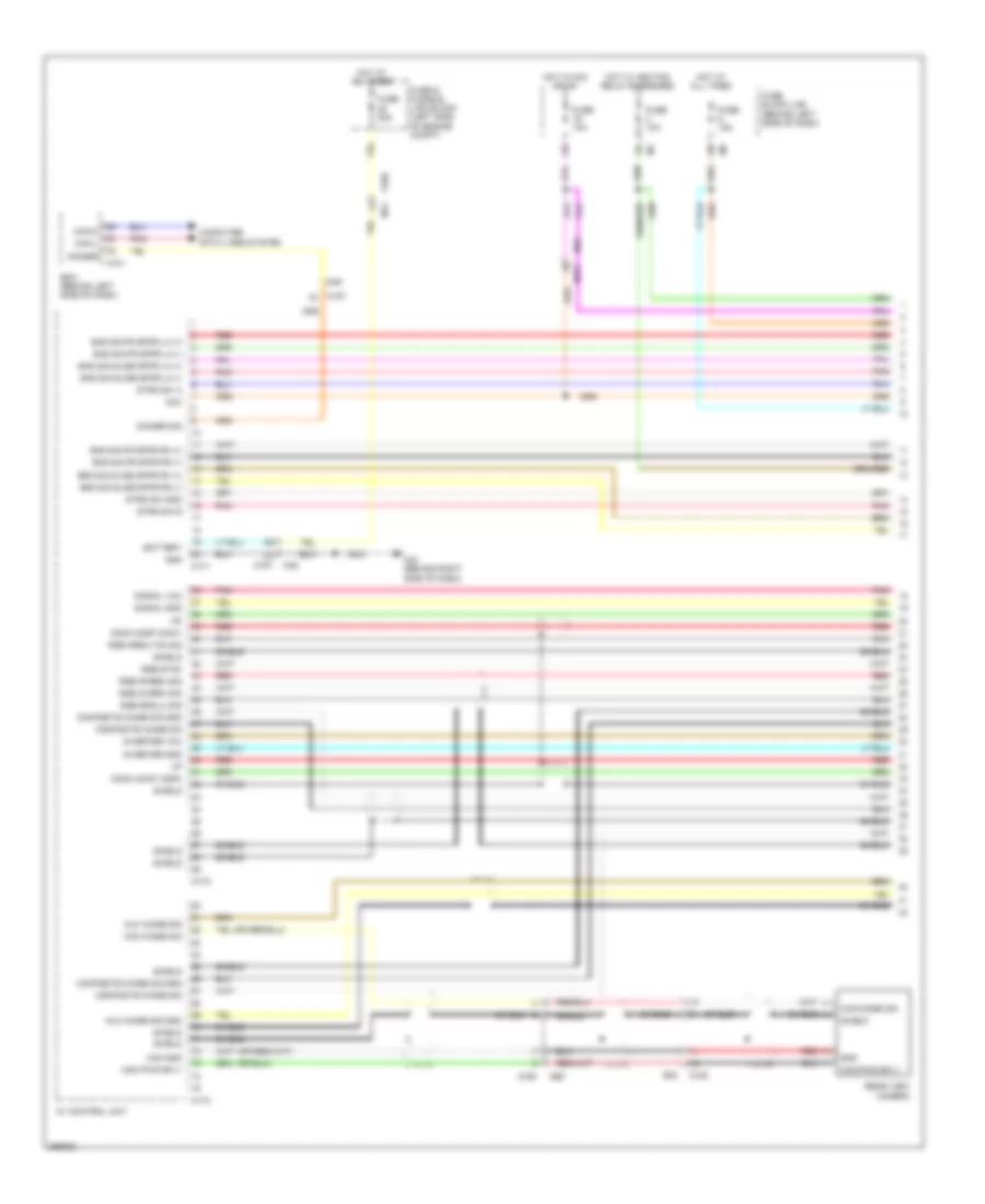
Automatic A/C Wiring Diagram (1 of 3) for Nissan Quest LE 2013
 https://portal-diagnostov.com/license.html
Automotive Electricians Portal FZCO
Automotive Electricians Portal FZCO
https://portal-diagnostov.com/license.html
https://portal-diagnostov.com/license.html
Automotive Electricians Portal FZCO
Automotive Electricians Portal FZCO
List of elements for Automatic A/C Wiring Diagram (1 of 3) for Nissan Quest LE 2013:
- A/c auto amp
- A/c auto amp conn- ection recognition sig
- A/c auto amp connection recognition sig
- A/c on sig
- Acc pwr sply
- Ambient sens gnd
- Ambient sens sig
- Amp
- B237
- Batt pwr sply
- Battery terminal w/ fusible link
- Blwr fan on sig
- Can-h
- Can-l
- Combination meter
- Comm
- Computer data lines system
- Defogger system
- Defogger system interior lights system
- Dr mtr pwr sply
- E101
- E103
- E105
- E13
- E309 (front left of engine compt)
- E339
- Eng coolant temp sig
- Exh gas/outside dr detecting sens sig
- Exhaust gas/outside odor detecting sensor (w advanced climate control system) (front of engine compt)
- Front blower motor (behind right side of dash)
- Front blower relay
- Front in-vehicle sensor (behind center of dash)
- Frt blwr mtr ctrl sig
- Frt in-veh sens sig
- Fuse 10a
- Fuse 15a
- Fuse block (j/b) (behind left side of dash)
- Fusible link n 100a
- Gnd
- Hot at all times
- Hot in acc or on
- Hot in on or start
- Hot w/ ignition relay energized
- Ign pwr sply
- Ill gnd
- Ill pwr sply
- Intake sens sig
- Intake sensor (behind lower center of center console)
- Interior lights system
- Ionizer on/off ctrl sig
- Lin sig
- M11
- M28
- M43 (behind right side of dash)
- M76 (behind left side of dash)
- Pnk
- Rear in-vehicle sensor (right rear of vehicle)
- Red
- Rr blwr mtr ctrl sig
- Rr in-veh sens sig
- Rr window def f/b sig
- Rr window def on sig
- Sens gnd
- Sunload sens sig
- Sunload sensor (top left of dash)
- Veh spd sig
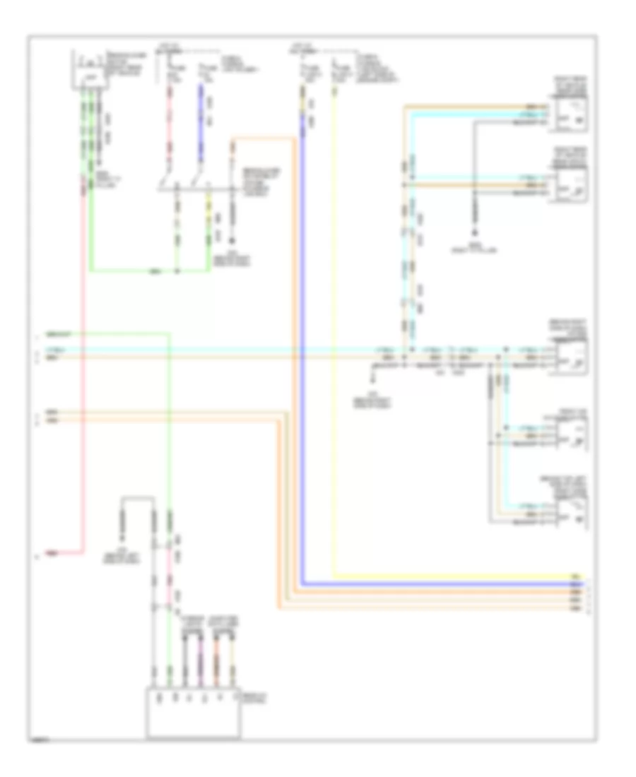
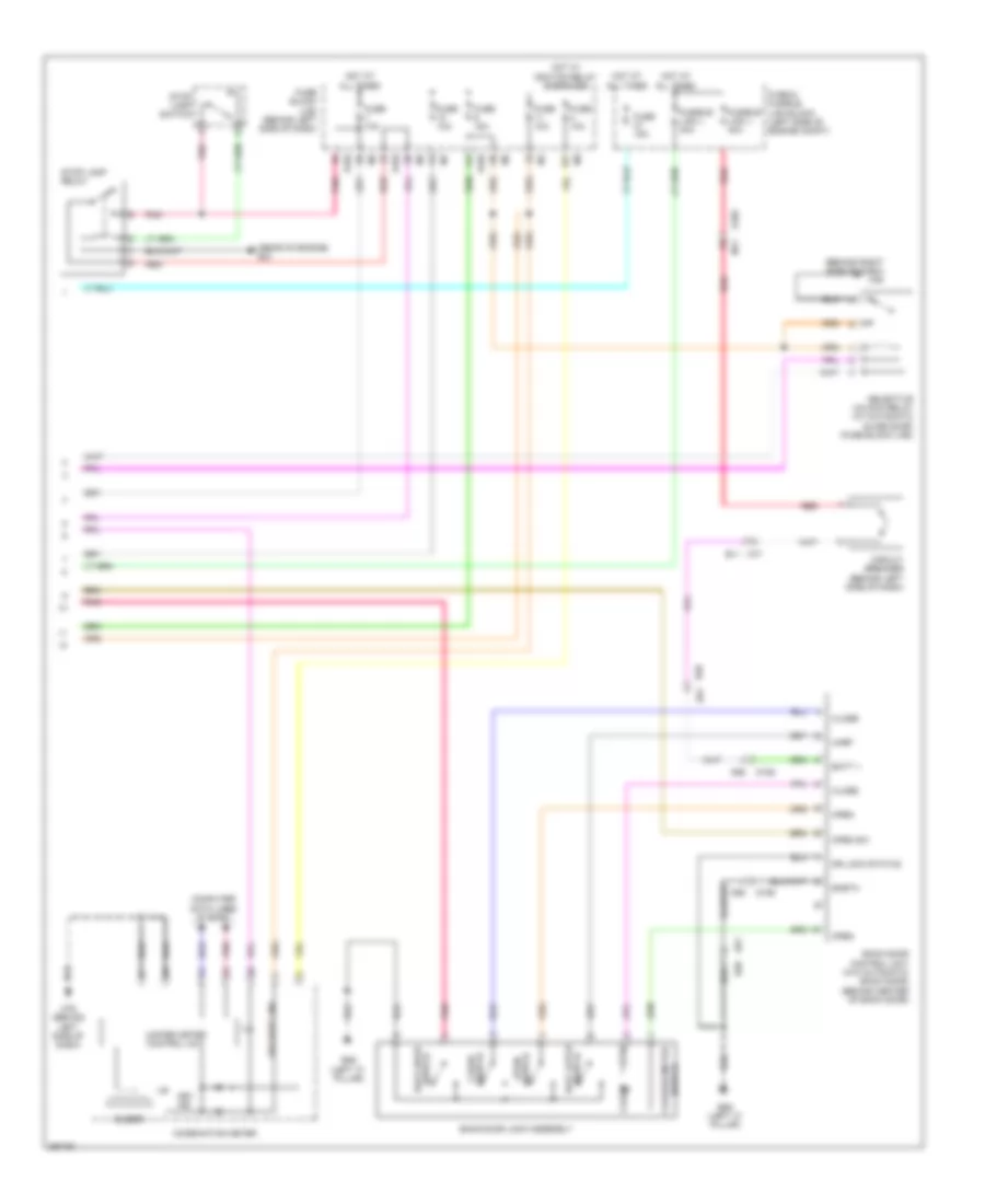
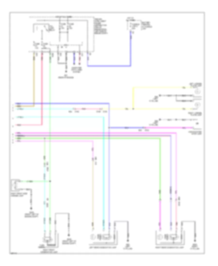
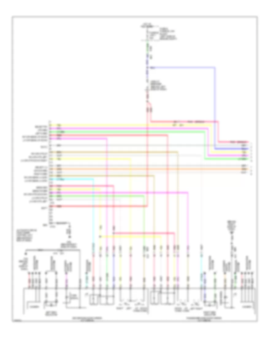
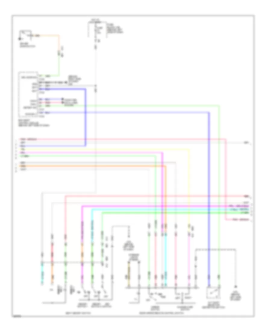
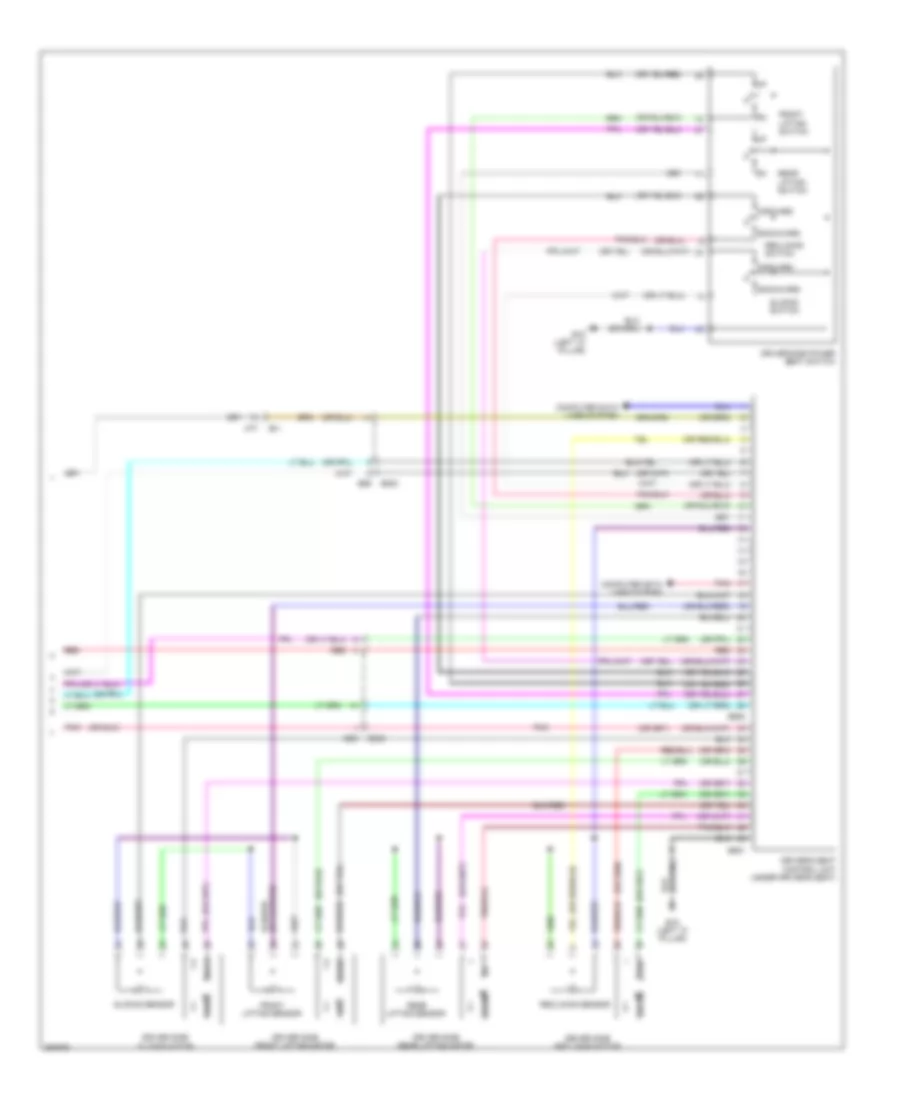
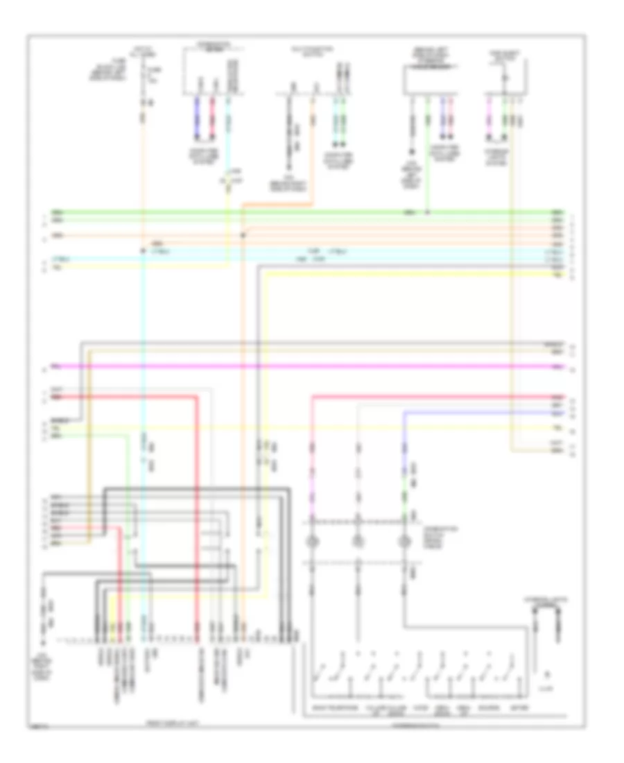
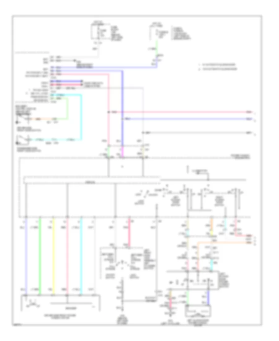
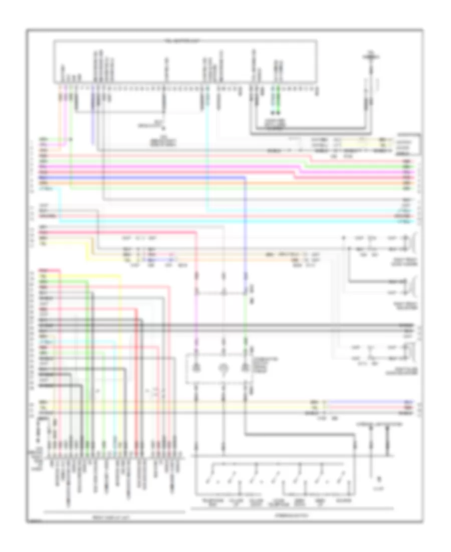
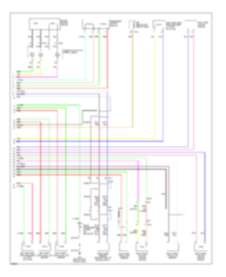
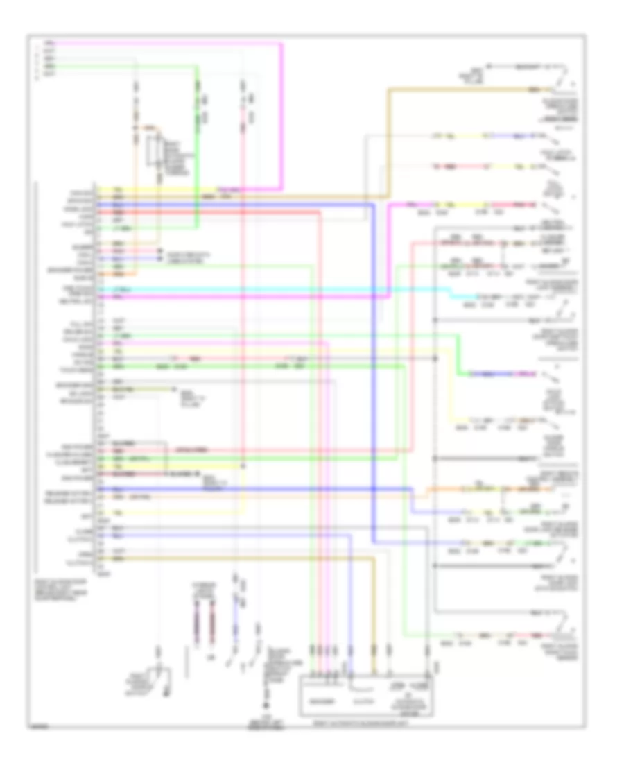
Automatic A/C Wiring Diagram (2 of 3) for Nissan Quest LE 2013
List of elements for Automatic A/C Wiring Diagram (2 of 3) for Nissan Quest LE 2013:
- (behind center of dash) left front air mix door motor
- (behind right center of dash) right front air mix door motor
- (behind right side of dash) intake door motor
- (behind top left side of dash) front mode door motor
- (or pnk)
- Amp
- B208 (right "c" pillar)
- B230
- B231
- B237
- B401
- B402
- Computer data lines system
- E105
- E305
- E70
- Fuse & fusible link block (left side of engine compt)
- Fuse & fusible link holder 1
- Fuse 15a
- Fusible link k 40a
- Fusible link m 40a
- Gnd
- Hot at all times
- Ign
- Ill+
- Ill-
- Interior lights system
- Ion-on off
- Ionizer (behind left side of dash)
- M11
- M22
- M28
- M302
- M43 (behind right side of dash)
- M76 (behind left side of dash)
- M81
- Pnk
- R106
- R107
- Rear a/c control
- Rear air mix door motor (right rear of vehicle)
- Rear blower motor (right rear of vehicle)
- Rear blower motor relay (in fuse & fusible link box)
- Rear mode door motor (right rear of vehicle)
- Red
- W/ accs (advanced climate control system)
- W/o accs (advanced climate control system)
- W/o rear entertainment
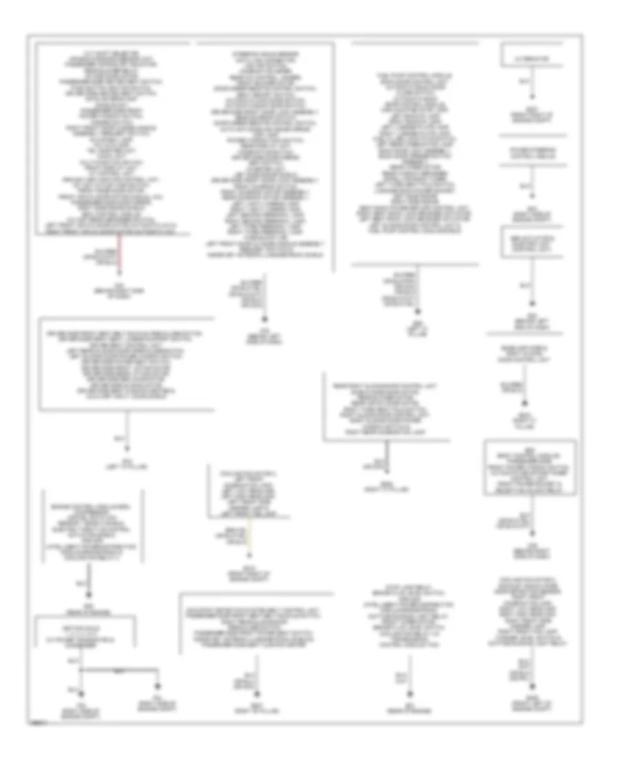
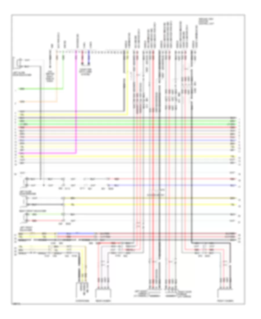
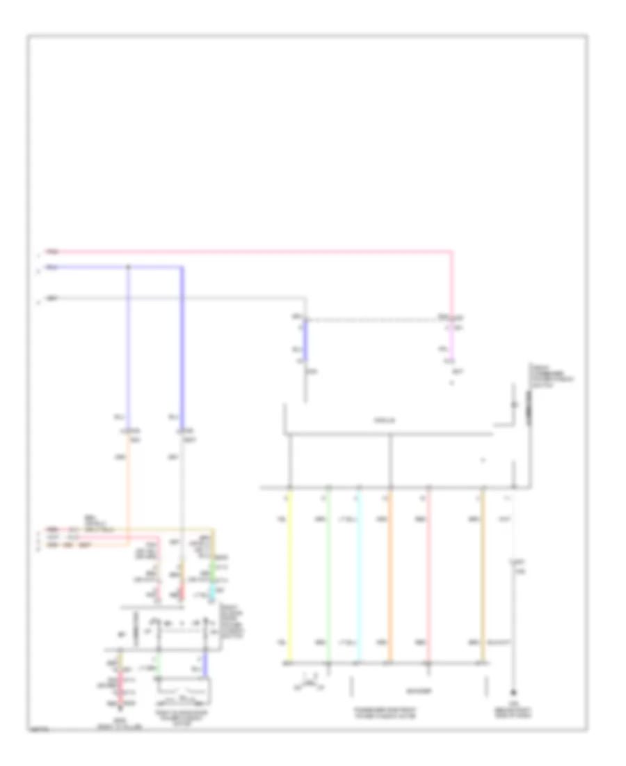
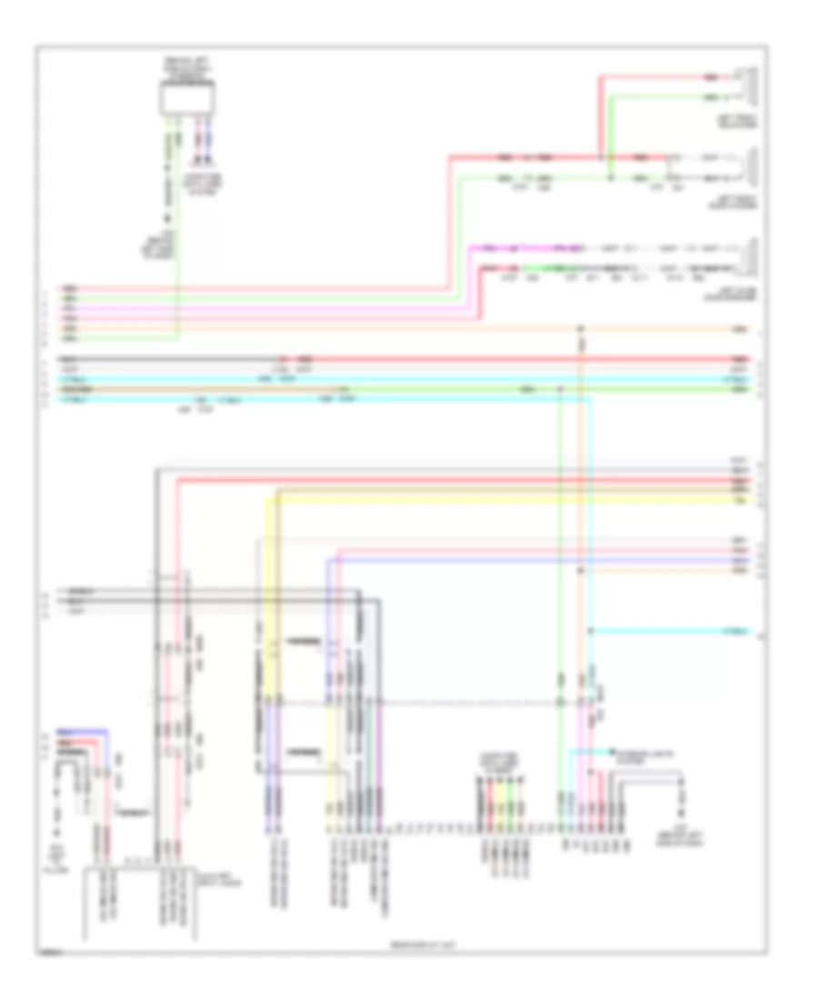
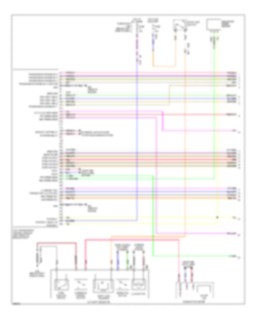
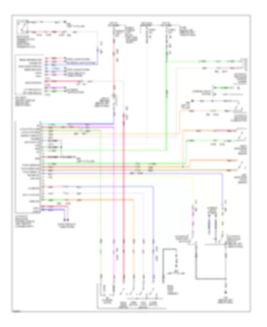
Automatic A/C Wiring Diagram (3 of 3) for Nissan Quest LE 2013
List of elements for Automatic A/C Wiring Diagram (3 of 3) for Nissan Quest LE 2013:
- (in ipdm e/r (intelligent power distribution module engine room)) cooling fan relay 2
- (in ipdm e/r (intelligent power distribution module engine room)) cooling fan relay 3
- A/c on
- A/c relay
- Ambient sensor (behind center of front bumper)
- Bcm (body control module) (behind left side of dash)
- Blwr fan on
- Blwr rly cont out
- Can comm line
- Can-h
- Can-l
- Compressor
- Computer data lines system
- Cooling fan motor 1 (behind left side of radiator)
- Cooling fan motor 2 (behind right side of radiator)
- Cooling fan relay 1
- Cpu
- E10
- E105
- E11
- E16
- E21 (rear of engine)
- E305
- E309 (front left of engine compt)
- E310 (front right of engine compt)
- E346
- E38 (rear of engine)
- E70
- Ecm (front left side of engine)
- Engine coolant temperature sensor (left rear of engine)
- F12
- F121
- F123
- Fuse 10a
- Hot at all times
- Hot in on or start
- Ignition relay
- Ipdm e/r (intelligent power distribution module engine room) (left side of engine compt)
- M11
- M121
- M124
- Pnk
- Red
- Refr pr sens
- Refrigerant pressure sensor (left front of engine compt)
- Sens gnd
- Sens pwr sply eng coolant temp true sens sens gnd
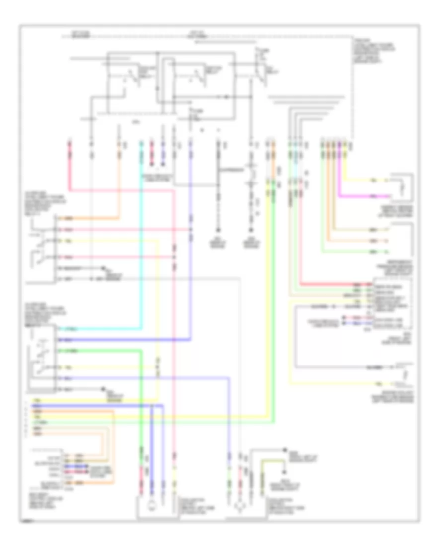
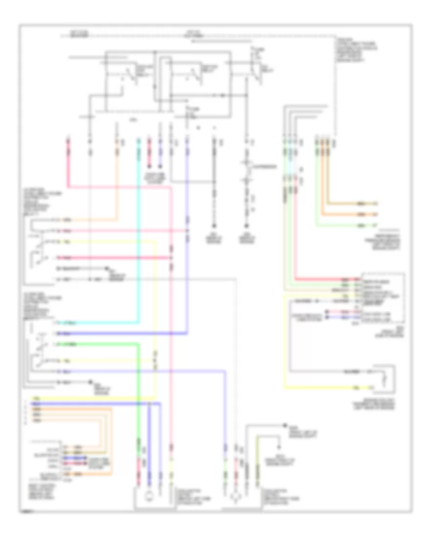
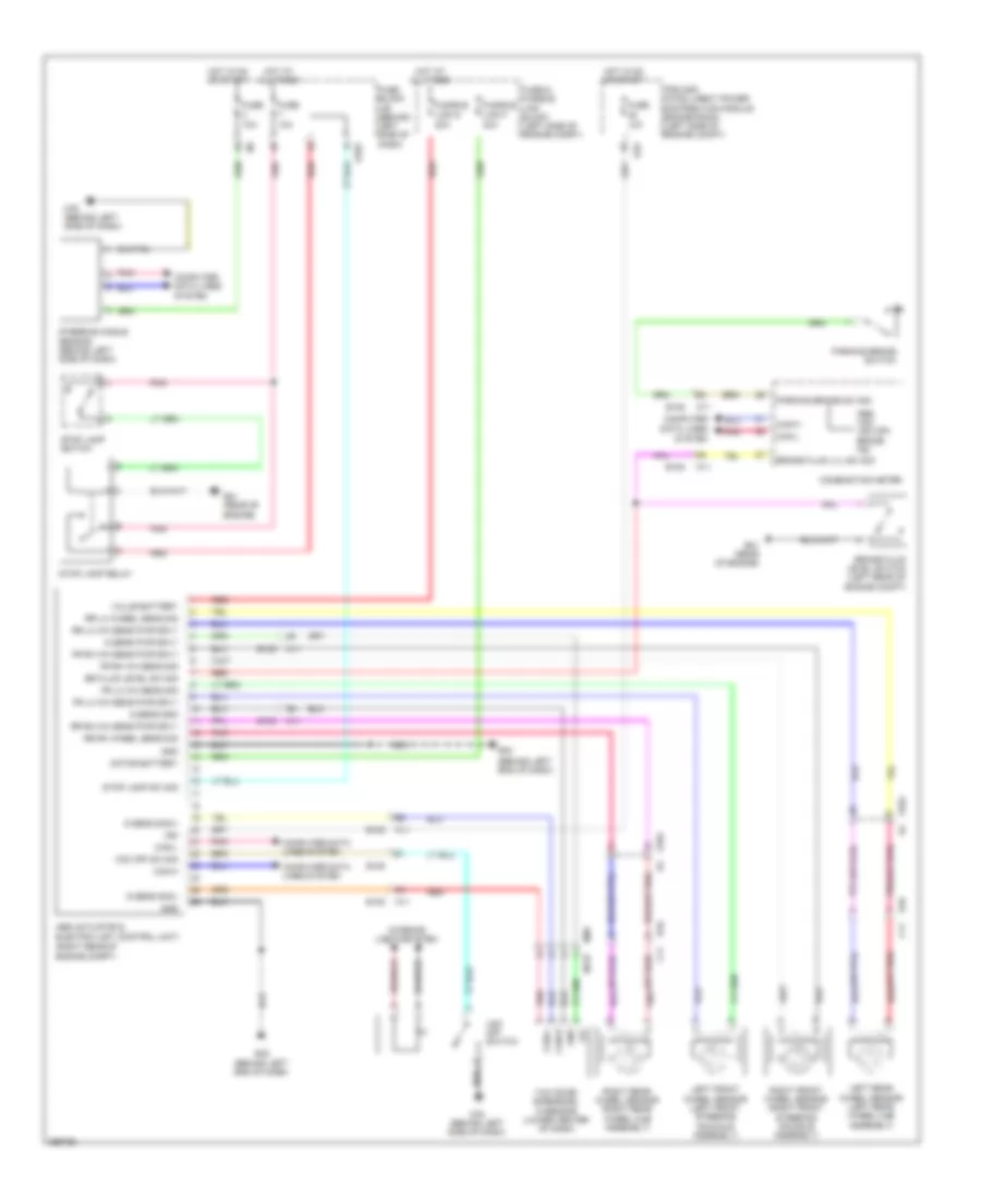
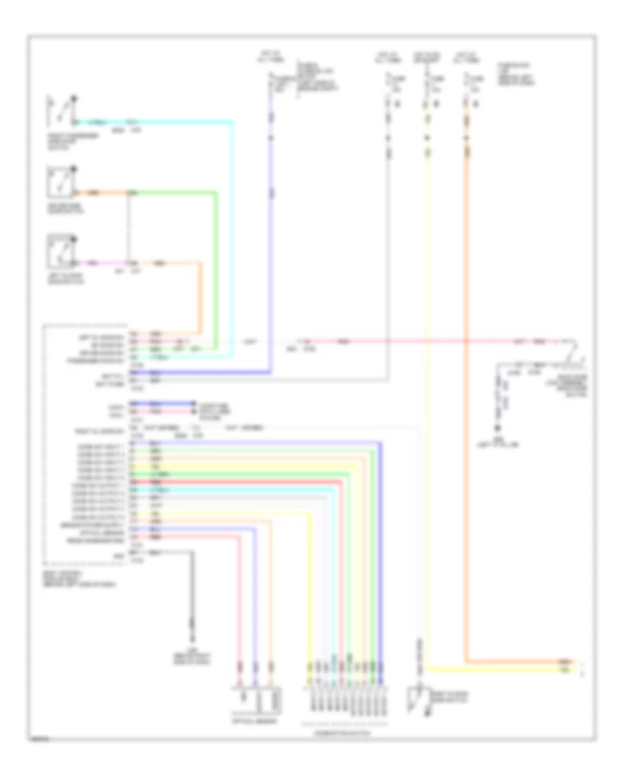
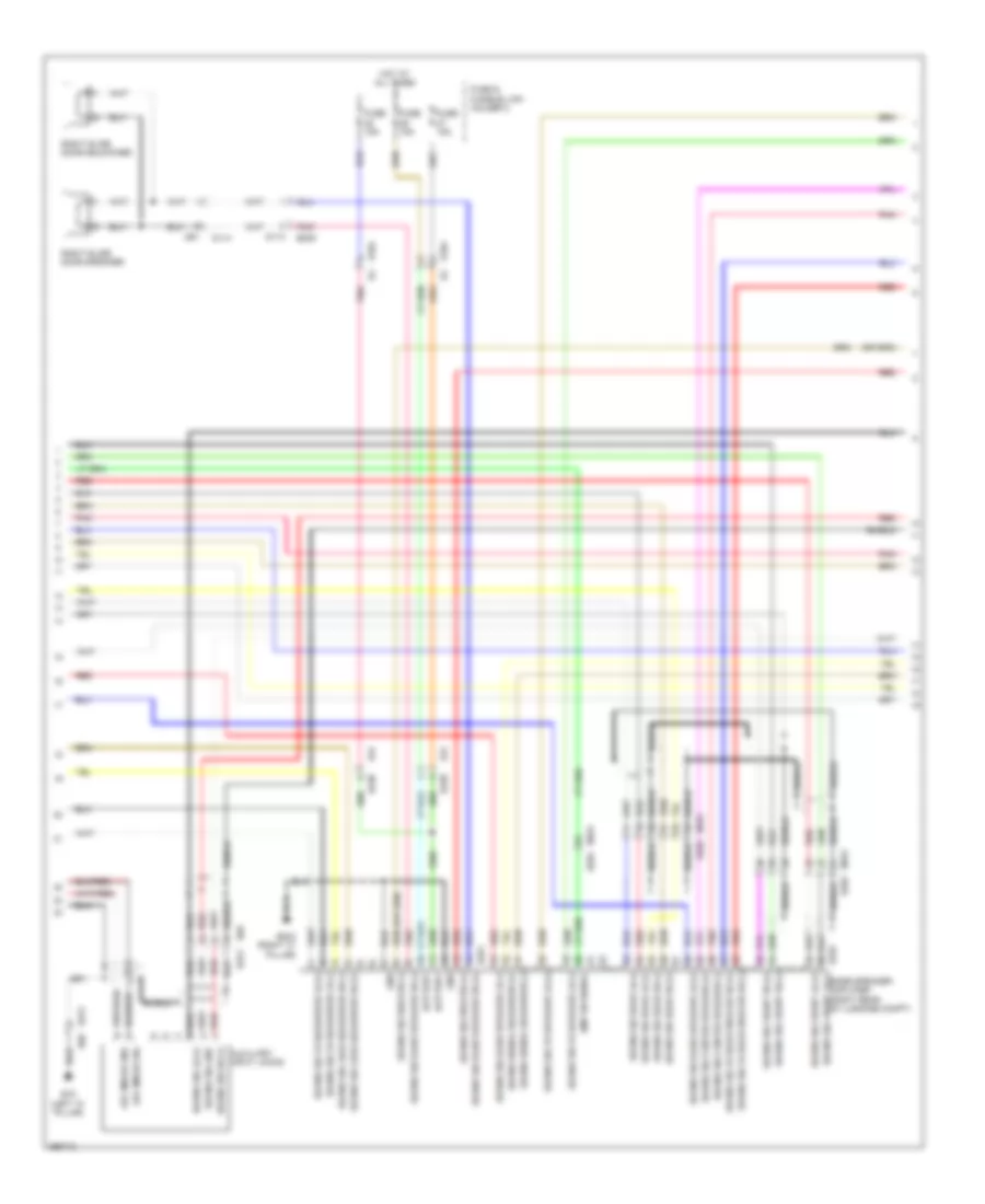
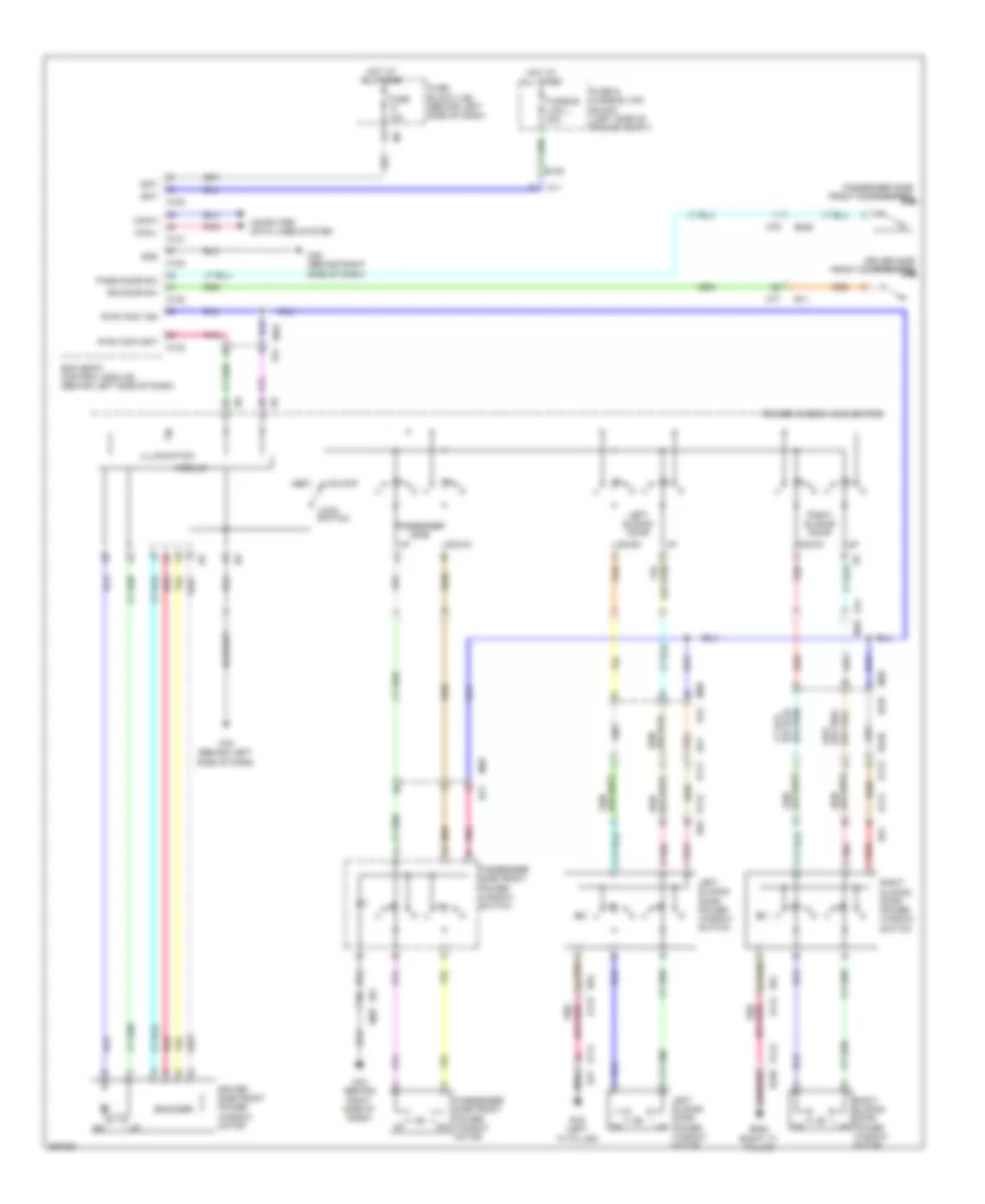
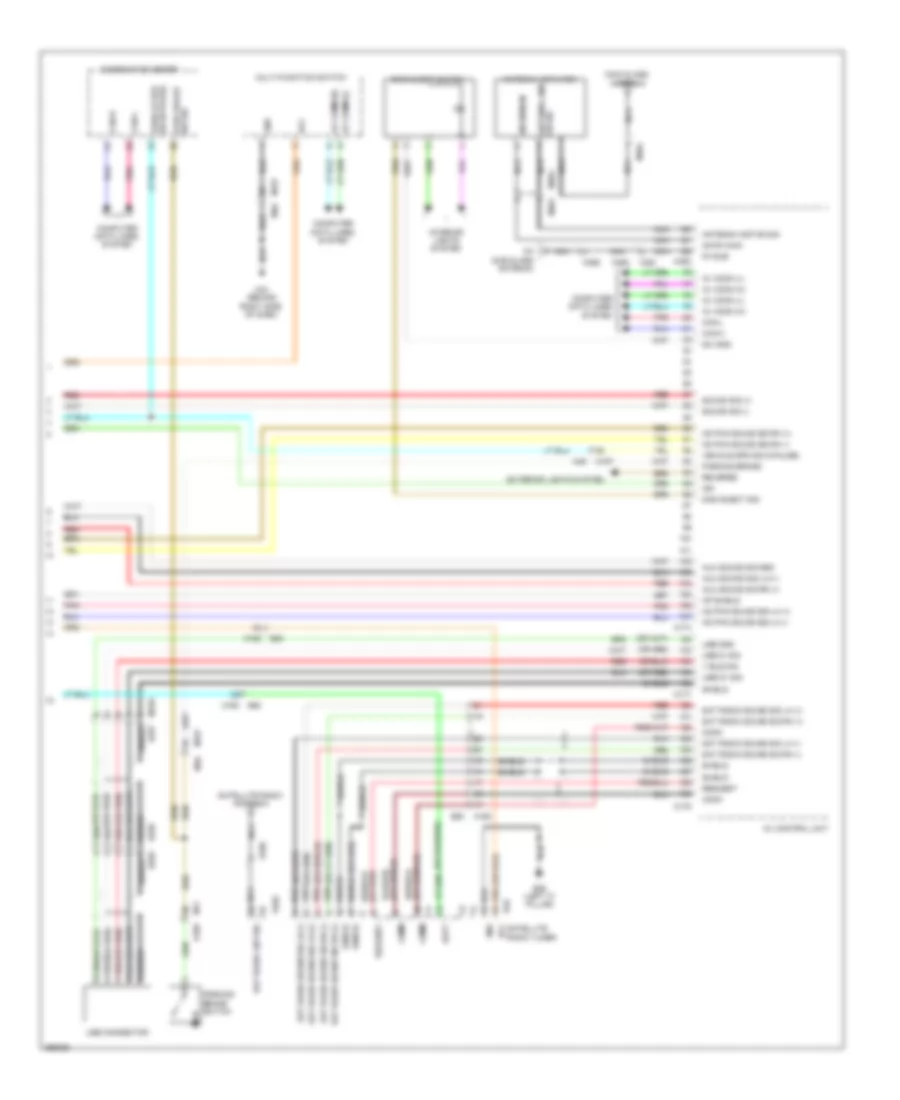
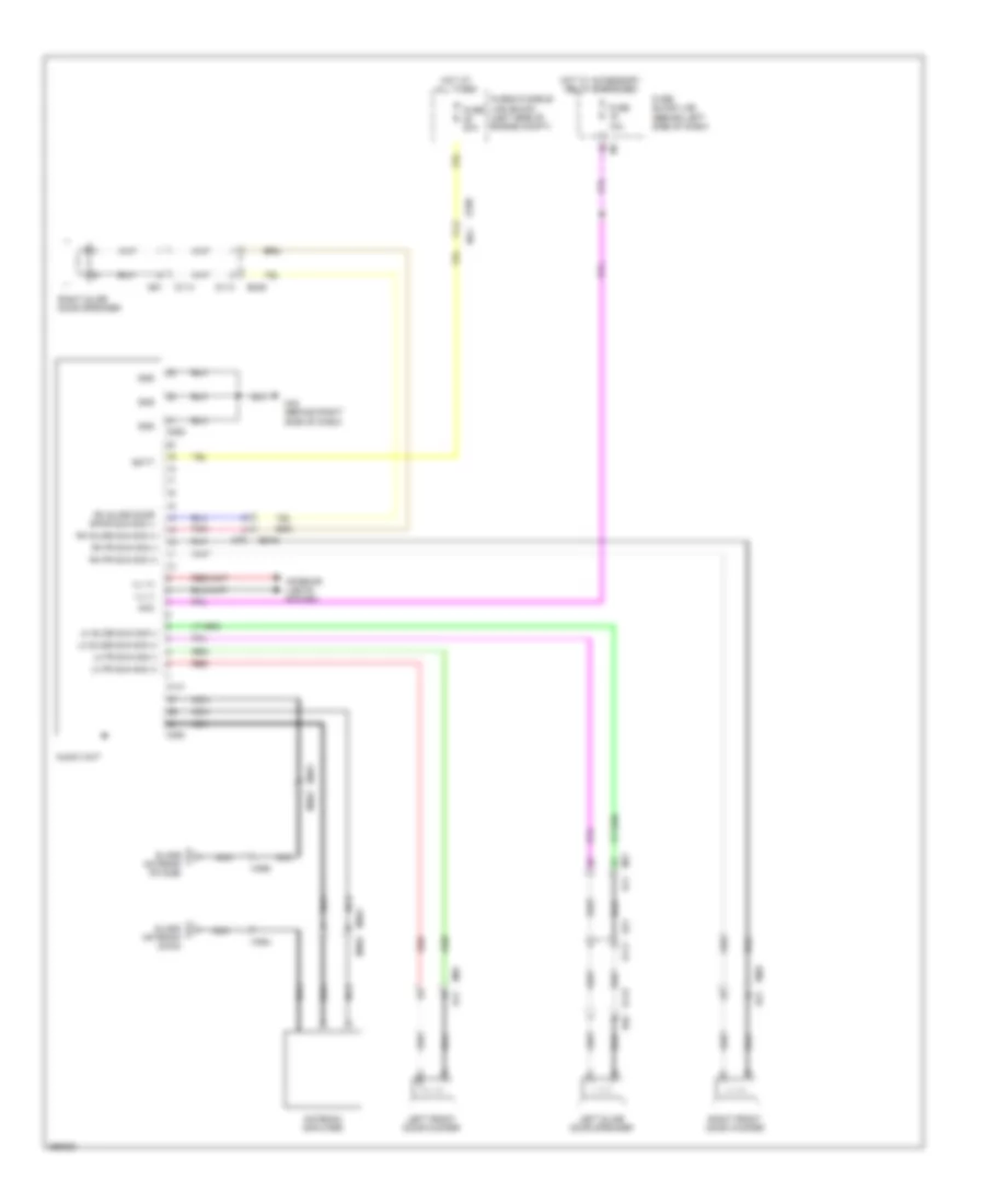
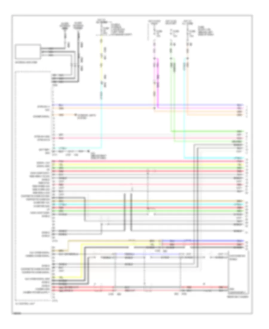
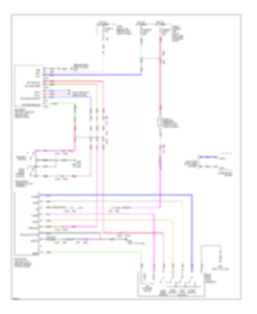
Manual A/C Wiring Diagram (1 of 3) for Nissan Quest LE 2013
List of elements for Manual A/C Wiring Diagram (1 of 3) for Nissan Quest LE 2013:
- A/c auto amp
- A/c on sig
- Acc pwr sply
- Amp
- Batt pwr sply
- Battery terminal w/ fusible link
- Blwr fan on sig
- Can-h
- Can-l
- Combination meter
- Comm
- Computer data lines system
- Defogger system
- Defogger system interior lights system
- Dr mtr pwr sply
- E101
- E13
- Eng coolant temp sig
- Front blower motor (behind right side of dash)
- Front blower relay
- Frt blwr mtr ctrl sig
- Fuse 10a
- Fuse 15a
- Fuse block (j/b) (behind left side of dash)
- Fusible link n 100a
- Gnd
- Hot at all times
- Hot in on or acc
- Hot in on or start
- Hot w/ ignition relay energized
- Ign pwr sply
- Ill gnd
- Ill pwr sply
- Intake sens sig
- Intake sensor (behind lower center of center console)
- Interior lights system
- Lin sig
- M43 (behind right side of dash)
- M76 (behind left side of dash)
- Pnk
- Red
- Rr blwr mtr ctrl sig
- Rr window def f/b sig
- Rr window def on sig
- Sens gnd
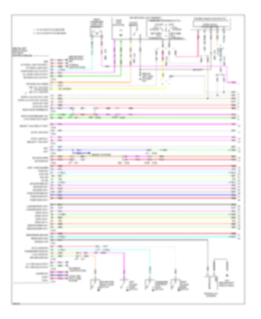
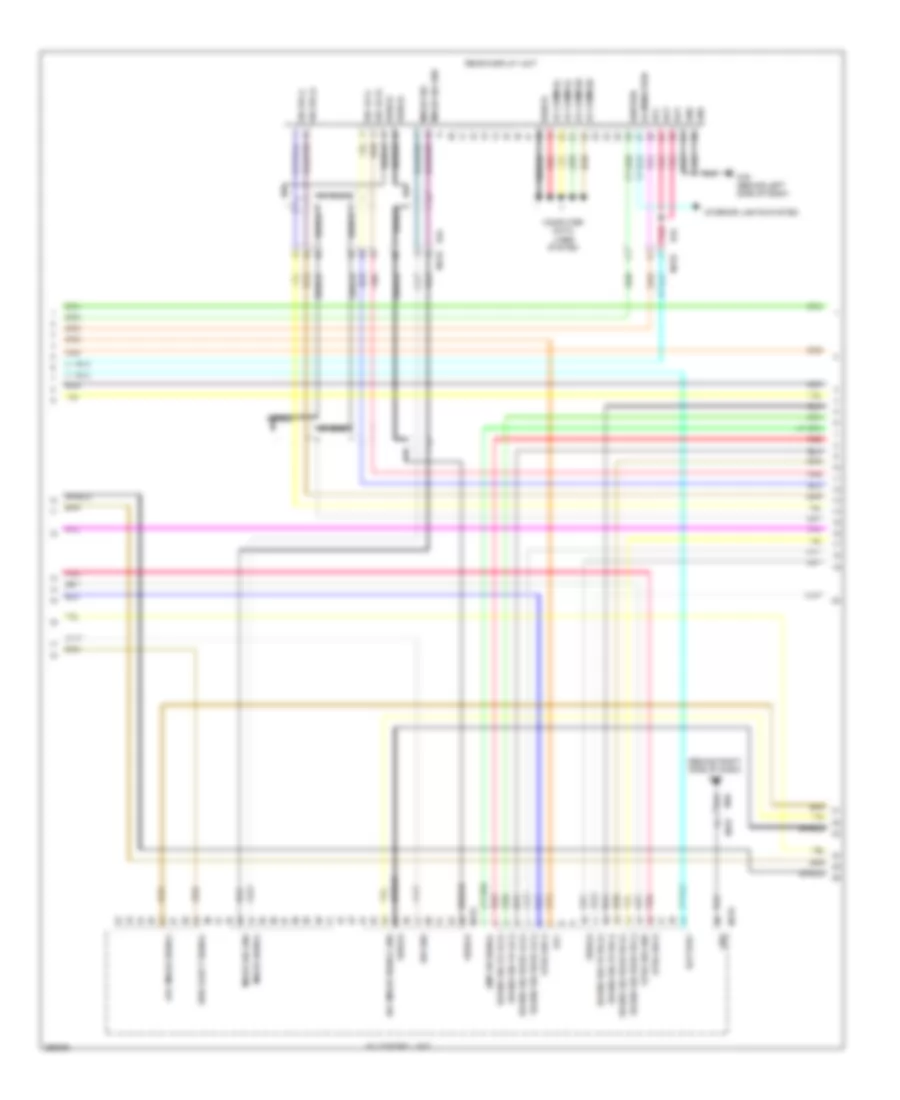
Manual A/C Wiring Diagram (2 of 3) for Nissan Quest LE 2013
List of elements for Manual A/C Wiring Diagram (2 of 3) for Nissan Quest LE 2013:
- (behind right side of dash) intake door motor
- (behind top left side of dash) front mode door motor
- (right rear of vehicle) rear air mix door motor
- (right rear of vehicle) rear mode door motor
- Amp
- B208 (right "c" pillar)
- B230
- B231
- B237
- B401
- B402
- Computer data lines system
- E105
- E305
- E70
- Front air mix door motor
- Fuse & fusible link block (left side of engine compt)
- Fuse & fusible link holder 1
- Fuse 15a
- Fuse link k 40a
- Fuse link m 40a
- Gnd
- Hot at all times
- Ign
- Ill+
- Ill-
- Interior lights system
- M11
- M22
- M28
- M302
- M43 (behind right side of dash)
- M76 (behind left side of dash)
- M81
- Pnk
- R106
- R107
- Rear a/c control
- Rear blower motor (right rear of vehicle)
- Rear blower motor relay (in fuse & fusible link box)
- Red
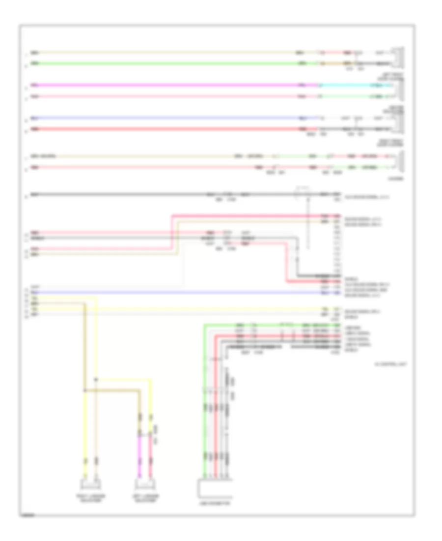
Manual A/C Wiring Diagram (3 of 3) for Nissan Quest LE 2013
List of elements for Manual A/C Wiring Diagram (3 of 3) for Nissan Quest LE 2013:
- (in ipdm e/r (intelligent power distribution module engine room)) cooling fan relay 2
- (in ipdm e/r (intelligent power distribution module engine room)) cooling fan relay 3
- A/c on
- A/c relay
- Blwr fan on
- Blwr rly cont out
- Body control module (bcm) (behind left side of dash)
- Can comm line
- Can-h
- Can-l
- Compressor
- Computer data lines system
- Cooling fan motor 1 (behind left side of radiator)
- Cooling fan motor 2 (behind right side of radiator)
- Cooling fan relay 1
- Cpu
- E10
- E11
- E16
- E21 (rear of engine)
- E305
- E309 (front left of engine compt)
- E310 (front right of engine compt)
- E346
- E38 (rear of engine)
- E70
- Ecm (front left side of engine)
- Engine coolant temperature sensor (left rear of engine)
- F12
- F121
- F123
- Fuse 10a
- Hot at all times
- Hot in on or start
- Ignition relay
- Ipdm e/r (intelligent power distribution module engine room) (left side of engine compt)
- M121
- M124
- Pnk
- Red
- Refr pr sens
- Refrigerant pressure sensor (left front of engine compt)
- Sens gnd
- Sens pwr sply eng coolant temp true sens sens gnd
ANTI-LOCK BRAKES
Anti-lock Brakes Wiring Diagram for Nissan Quest LE 2013
List of elements for Anti-lock Brakes Wiring Diagram for Nissan Quest LE 2013:
- (behind left end of dash)
- (or pnk)
- (or red)
- (right rear of engine compt)
- 10a
- 12v
- 20a
- 30a
- Abs actuator & electric unit (control unit)
- Abs, vdc, vdc off, brake ind
- B10
- Br fluid level sw sig
- Brake fluid level switch (left rear of engine compt)
- Brake fluid lvl sw sig
- C11
- Can-h
- Can-l
- Combination meter
- Computer data lines
- Computer data lines system
- E10
- E103
- E104
- E105
- E21 (rear of engine)
- E42
- E42 (behind left end of dash)
- Fr lh wh sens pwr sply
- Fr lh wh sens sig
- Fr rh wh sens pwr sply
- Fr rh wh sens sig
- Fuse
- Fuse & fusible link block (left side of engine compt)
- Fuse block j/b (behind left side of dash)
- Fusible link f
- Fusible link g
- G sens gnd
- G sens pwr sply
- G sens sig(+)
- G sens sig(-)
- Gnd
- Hot at all times
- Hot in on or start
- Ign
- Interior lights system
- Ipdm e/r (intelligent power distribution module engine room) (left side of engine compt)
- Left front wheel sensor (left front steering knuckle assembly)
- Left rear wheel sensor (left rear wheel hub assembly)
- M11
- M137
- M58
- M76 (behind left side of dash)
- Motor battery
- Parking brake sw sig
- Parking brake switch
- Pnk
- Red
- Right front wheel sensor (right front steering knuckle assembly)
- Right rear wheel sensor (right rear wheel hub assembly)
- Rr lh wh sens pwr sply
- Rr lh wheel sens sig
- Rr rh wh sens pwr sply
- Rr rh wheel sens sig
- Steering angle sensor (behind left side of dash)
- Stop lamp relay
- Stop lamp sw sig
- Stop lamp switch
- System
- Value battery
- Vdc off sw sig
- Vdc off switch
- Yaw rate/ side/decel g sensor (lower center of dash)
ANTI-THEFT
Anti-theft Wiring Diagram (1 of 4) for Nissan Quest LE 2013
List of elements for Anti-theft Wiring Diagram (1 of 4) for Nissan Quest LE 2013:
- (behind left side of dash) bcm (body control module)
- (behind left side of dash) m76
- (behind right side of dash) m35
- Acc ind
- All door lock output
- B11
- B225
- B32
- Back door opener sw
- Back door request sw
- Bat
- Between full stroke & n
- Bk door open
- Bk door sw
- Can-h
- Can-l
- Computer data lines system
- D152
- D159
- D188
- D21
- D41 m18
- Dongle link
- Dongle unit (canada)
- Door key cylinder switch
- Door lk & unlk sw lock
- Door lk & unlk sw unlock
- Door lock & unlock switch
- Door lock actuator
- Dr door ant+
- Dr door ant-
- Dr door req sw
- Dr door unlk output
- Dr door unlk sens
- Driver door lock assembly
- Driver door sw
- Driver side front door switch
- E105
- Exterior lights system
- Front passenger door lock assembly
- Full stroke
- Gnd
- Hazard sw
- I-key warn buzzer
- Int room lamp cont
- Int room lamp pwr sply
- Interface
- Interior lights system
- Key cyl unlk sw pw sw comm key cyl lock sw
- Left sliding door switch
- Lh sl door sw
- Lh sl door unlk cont
- Lh turn sig output
- Lock
- Lock ind
- Luggage room ant+
- Luggage room ant-
- M11
- M121
- M122
- M123
- M124
- M20
- M43 (behind right side of dash)
- M77
- M79
- Memory systems
- Nats ant amp
- On ind
- Pass door ant+
- Pass door ant-
- Pass door req sw
- Pass door unlk output
- Passenger door sw
- Passenger side front door switch
- Pnk
- Power window main switch
- Push sw
- Rear bumper ant+
- Rear bumper ant-
- Receiver comm
- Red
- Rh sl door sw
- Rh turn sig output
- Right sliding door switch
- Room ant1+
- Room ant1-
- Room ant2+
- Room ant2-
- Security ind cont
- Select unlk relay cont
- Sens/receiver gnd
- Stop lamp sw1
- Stop lamp sw2
- Unlock
- Unlock sensor
- W/ automatic slide door
- W/o automatic slide door
Anti-theft Wiring Diagram (2 of 4) for Nissan Quest LE 2013
List of elements for Anti-theft Wiring Diagram (2 of 4) for Nissan Quest LE 2013:
- (w/ automatic slide door) passenger side front power window switch
- (w/o automatic slide door) passenger side front power window switch
- B11
- B207 (right "b" pillar)
- B225
- B237
- B239
- B28
- B310
- B42
- Bat
- Batt
- Clk
- Console inside key antenna
- D111 b21
- D112
- D113
- D114
- D21
- D21 m20
- D61
- D62
- Data
- Door lock & unlock switch
- E7 f121
- Gnd
- Instrument center inside key antenna
- Left sliding door lock assembly
- Luggage room inside key antenna
- M11 e105
- M20
- M22
- M28
- M35 (behind right side of dash)
- M38
- M43 (behind right side of dash)
- M77
- M79
- Memory systems
- Nats antenna amplifier
- Pnk
- R106
- Rear bumper outside key antenna
- Red
- Remote keyless entry receiver (center of roof)
- Right sliding door lock assembly
- Shield
- Sig out
- W/ automatic slide door
- W/o automatic slide door
Anti-theft Wiring Diagram (3 of 4) for Nissan Quest LE 2013
List of elements for Anti-theft Wiring Diagram (3 of 4) for Nissan Quest LE 2013:
- Acc ind
- B26 (left "c" pillar)
- Back door opener switch assembly
- Computer data lines system
- Cpu
- E10
- E105
- E11
- E21 (rear of engine)
- F12
- Fuse 15a
- Headlamp high relay
- Headlamp low relay
- Headlights system
- Horn relay (in fuse & fusible link box)
- Horns system
- Hot at all times
- Intelligent key warning buzzer (engine room)
- Ipdm e/r (intelligent power distribution module engine room) (left side of engine compt)
- Left front door outside handle assembly
- Lock ind
- M11
- M18 d41
- M20 d21
- M43 (behind right side of dash)
- M76 (behind left side of dash)
- On ind
- Opener sw back door
- Outside key antenna
- Pnk
- Push button ignition switch (left center of dash)
- Push switch
- Red
- Request switch
- Right front door outside handle assembly
- Starter control relay
- Starter relay
- Starting/ charging system
Anti-theft Wiring Diagram (4 of 4) for Nissan Quest LE 2013
List of elements for Anti-theft Wiring Diagram (4 of 4) for Nissan Quest LE 2013:
- (behind right side of dash) m35
- (rear of engine) e21
- 11f
- 12c
- B20
- B20 d91
- B26 (left "c" pillar)
- Back door control unit (w/o automatic back door) (behind center of back door)
- Back door lock assembly
- Back door switch
- Batt +
- Buzzer
- Circuit breaker (behind left side of dash)
- Close
- Closure motor switch
- Combination meter
- Computer data lines system
- D158
- D91
- D92
- Dr lock status
- E103
- E105
- Earth
- Fuse & fusible link block (left side of engine compt)
- Fuse 10a
- Fuse 15a
- Fuse block (j/b) (behind left side of dash)
- Fusible link j 40a
- Fusible link l 40a
- Half latch switch
- Harf
- Hot at all times
- Hot w/ ignition relay energized
- Key ind
- M11
- M76 (behind left side of dash)
- M77 b11
- Open
- Open sw
- Pnk
- Red
- Security ind
- Selective unlock relay (w/ automatic slide door) (fuse block (j/b))
- Stop lamp relay
- Stop lamp switch
- Switch close
- Switch open
- Unified meter control unit
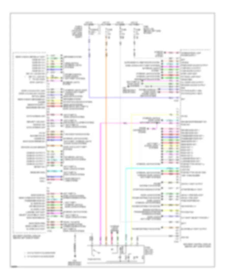
BODY CONTROL MODULES
Body Control Modules Wiring Diagram for Nissan Quest LE 2013
List of elements for Body Control Modules Wiring Diagram for Nissan Quest LE 2013:
- A/c on
- Acc
- Acc ind
- Acc rly cont output
- Air bag
- Air conditioning system
- All door lock output
- Anti theft & door locks systems
- Anti theft & door locks systems wiper/washer system
- Anti theft, interior lights & door locks systems
- Anti-theft & door locks systems
- Anti-theft & instrument cluster systems
- Anti-theft, interior lights & door locks systems
- Back door open
- Back door opener sw
- Back door req sw
- Back door sw
- Bat
- Batt
- Bcm (body control module) (behind left side of dash)
- Blower fan on
- Blwr relay cont output
- Can-h
- Can-l
- Combi sw in 1
- Combi sw in 2
- Combi sw in 3
- Combi sw in 4
- Combi sw in 5
- Combi sw output 1
- Combi sw output 2
- Combi sw output 3
- Combi sw output 4
- Combi sw output 5
- Computer data lines system
- Crank req
- Cvt shift select pwr sply
- Defogger system
- Detent sw
- Dimmer
- Dongle link
- Door lk & unlk sw lock
- Door lk & unlk sw unlock
- Door lock & anti-theft systems
- Door locks & anti-theft systems
- Door locks & interior lights systems
- Door locks system
- Dr door unlock output
- Dr door unlock sensor
- Driver door ant +
- Driver door ant -
- Driver door request sw
- Driver door sw
- Engine controls system
- Engine controls, transmissions & starting/ charging systems
- Exterior lights & headlights systems
- Exterior lights system
- Fuse & fusible link block (left side of engine compt)
- Fuse 10a
- Fuse block (j/b) (behind left side of dash)
- Fusible link l 40a
- Gnd
- Hazard sw
- Headlights & exterior lights systems
- Headlights system
- Headlights system headlights, anti-theft & door locks systems
- Hot at all times
- I-key warn buzzer
- Ign pwr sply 2
- Ign rly (f/b) cont
- Ign rly (ipdm e/r) cont
- Illumi- nation
- Int room lamp cont
- Interior lights & door locks anti-theft systems
- Interior lights system
- Interior lights, door locks & anti-theft systems
- Key cyl lock sw
- Key cyl unlock sw
- Lock
- Lock ind
- Luggage lamp cont
- Luggage room ant +
- Luggage room ant -
- M121
- M122
- M123
- M124
- M35 (behind right side of dash)
- M43 (behind right side of dash)
- Nats antenna amp
- Navigation & sound systems
- On ind
- Optical sens
- P/n position
- Pass door req sw
- Pass door unlock output
- Passenger door ant +
- Passenger door ant -
- Passenger door sw
- Pnk
- Power distribution system
- Power windows, door locks & anti-theft systems
- Power windows, door locks, power tops & seats systems
- Push button ignition switch
- Push sw
- Push switch
- Push-button ign sw gnd
- Push-button ign sw ill
- Pw sw comm
- Pwr sply
- Rear bmpr ant +
- Rear bmpr ant -
- Rear window def relay cont
- Rear window defogger sw
- Rear wiper output
- Rear wiper stop position
- Receiver comm
- Red
- Room ant 1+
- Room ant 1-
- Room ant 2+
- Room ant 2-
- Security ind cont
- Select unlck relay cont
- Sens/receiver gnd
- Sl door lh sw
- Sl door rh sw
- Sl door unlk cont
- Starter relay cont
- Starting/charging system
- Step lamp cont
- Stop lamp sw 1
- Trunk, tailgate fuel doors system wiper/washer system
- Turn sig lh output
- Turn sig rh output
- W/ automatic sliding door
- W/o automatic sliding door
- Warning, door locks & anti-theft systems
COMPUTER DATA LINES
Computer Data Lines Wiring Diagram for Nissan Quest LE 2013
List of elements for Computer Data Lines Wiring Diagram for Nissan Quest LE 2013:
- (right rear of engine compt) power steering control unit
- Abs actuator & electric unit (right rear of engine compt)
- Air bag diagnosis sensor unit (under lower center of dash)
- Around view monitor control unit
- Audio unit
- Automatic back door control module (if equipped) (left rear of luggage compt)
- Av comm h
- Av comm l
- Av control unit
- B11
- B208 (right "c" pillar)
- B228 b19
- B247
- B28
- B310
- B45
- B530
- B552
- B89
- Bcm (body control module) (behind left side of dash)
- Bsw comm-h
- Bsw comm-l
- Bsw control module (w/ navigation) (behind center of dash)
- Can-h
- Can-l
- Combination meter
- Cpu
- Data line
- Data link connector
- Driver seat control unit (w/ navigation)
- Driver side front seat
- E105
- E11
- E16
- E34
- Engine control module (ecm) (front left side of engine)
- F123
- Fuse 3 10a
- Fuse 6 10a
- Fuse block (j/b) (behind left side of dash)
- Hot at all times
- Hot in on or start
- Ipdm e/r (intelligent power distribution module engine room) (left side of engine compt)
- K-line
- Left side radar sensor (left rear corner of vehicle)
- Left sliding door control unit (behind left rear quarterpanel)
- M11
- M11 e105
- M121
- M139
- M157
- M170
- M174
- M180
- M46
- M46 m157
- M59
- M70
- M76 (behind left side of dash)
- M77
- M79 b225
- M93
- Multi-function switch
- Occupant detection system control unit (under front of passenger's seat)
- Pnk
- R34
- Rear display unit
- Red
- Right side radar sensor (right rear corner of vehicle)
- Right sliding door control unit (behind right rear quarterpanel)
- Shield
- Steering angle sensor (behind left side of dash)
- Tcm (transmission control module) (left front of engine compt)
- Tel adapter unit
- W/ automatic slide door
- W/ display audio
- W/ navigation
- W/ rear entertainment
- W/o automatic slide door
- W/o display audio
- W/o navigation
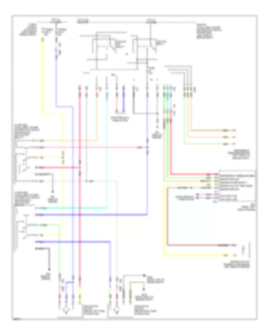
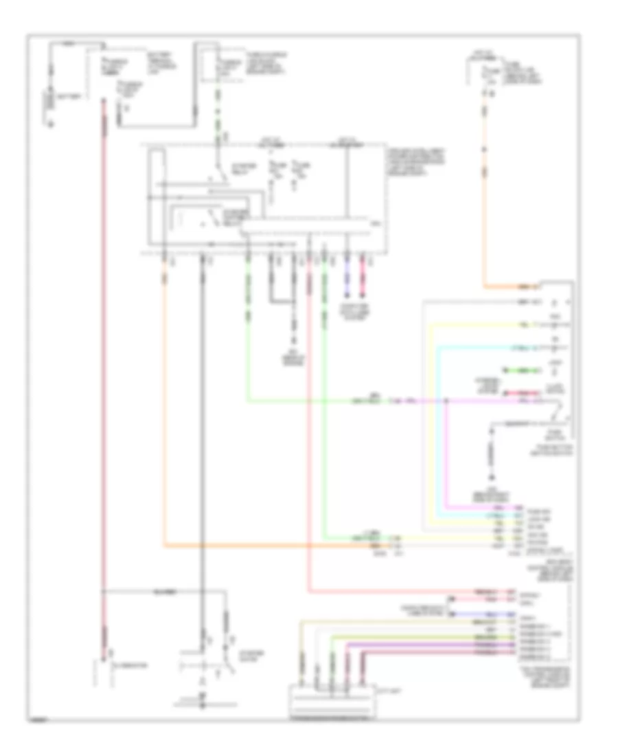
COOLING FAN
Cooling Fan Wiring Diagram for Nissan Quest LE 2013
List of elements for Cooling Fan Wiring Diagram for Nissan Quest LE 2013:
- (in ipdm e/r (intelligent power distribution module engine room)) cooling fan relay 2
- (in ipdm e/r (intelligent power distribution module engine room)) cooling fan relay 3
- Can comm line
- Computer data lines system
- Cooling fan motor 1 (behind left side of radiator)
- Cooling fan motor 2 (behind right side of radiator)
- Cooling fan relay 1
- Cpu
- E10
- E11
- E16
- E21 (rear of engine)
- E305
- E309 (front left of engine compt)
- E310 (front right of engine compt)
- E346
- E38 (rear of engine)
- E70
- Ecm (front left side of engine)
- Engine coolant temp sens
- Engine coolant temperature sensor (left rear of engine)
- F123
- Fuse & fusible link block (left side of engine compt)
- Fuse 10a
- Fusible link k 40a
- Fusible link m 40a
- Hot at all times
- Hot in on or start
- Ignition relay
- Ipdm e/r (intelligent power distribution module engine room) (left side of engine compt)
- Pnk
- Red
- Refrigerant pressure sens
- Refrigerant pressure sensor (left front of engine compt)
- Sensor ground
CRUISE CONTROL
Cruise Control Wiring Diagram for Nissan Quest LE 2013
List of elements for Cruise Control Wiring Diagram for Nissan Quest LE 2013:
- Accelerator pedal position sensor (behind left side of dash)
- Acsd steering switch
- Aps1
- Aps2
- Ascd brake switch (behind left side of dash)
- Ascd brk sw
- Ascd str sw
- Can comm line
- Can-h
- Can-l
- Cancel
- Close
- Combination meter
- Combination switch (spiral cable)
- Computer data lines system
- Cruise ind
- Cvt unit
- E10
- E103
- E105
- E16
- E21 (rear of engine)
- E38 (rear of engine)
- Ecm (front left side of engine)
- Ecm pwr sply
- Electric throttle control actuator (right rear of engine compt)
- F12
- Fuse 10a
- Fuse 51 15a
- Fuse block (j/b) (behind left side of dash)
- Gnd
- Hot at all times
- Hot w/ ignition relay energized
- Ipdm e/r (intelligent power distribution module engine room) (left side of engine compt)
- M11
- M303
- M33
- Main (on/off)
- Mtr (close)
- Mtr (open)
- Mtr pwr sply
- Mtr rly
- Nca
- Open
- Pnk
- Pri spd sens
- Primary speed sensor
- Red
- Resume/ accelerate
- Sec spd sens
- Secondary speed sensor
- Sens gnd
- Sens pwr
- Sens pwr sply
- Sensor 1
- Sensor 2
- Set/ coast
- Snsr gnd
- Snsr pwr
- Snsr pwr sply
- Stop lamp relay
- Stop lamp switch
- Stp lp sw
- Tcm (transmission control module) (left front of engine compt)
- Throttle control motor
- Throttle control motor relay
- Throttle position sensor
- Tps1
- Tps2
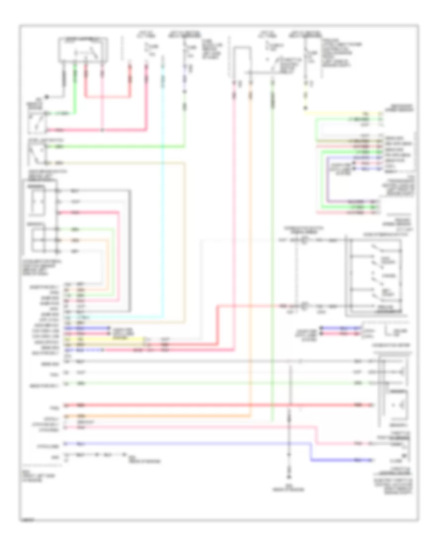
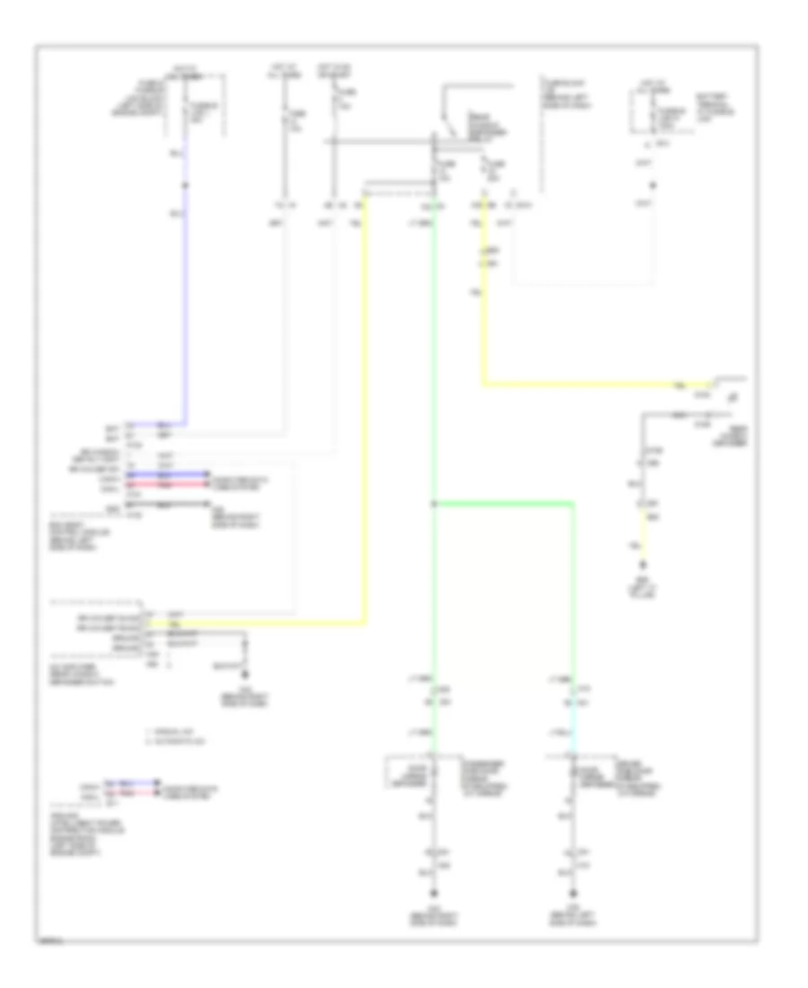
DEFOGGERS
Defoggers Wiring Diagram for Nissan Quest LE 2013
List of elements for Defoggers Wiring Diagram for Nissan Quest LE 2013:
- (left "c" pillar)
- 10g b6
- 1d e101
- 4b m2
- 7a m1
- A/c amplifier (rear window defogger switch)
- Automatic a/c
- B20
- B26
- Bat
- Battery terminal w/ fusible link
- Bcm (body control module) (behind left side of dash)
- Can-h
- Can-l
- Computer data lines system
- D158
- D184
- D185
- D21
- D41
- D91
- D92
- Def rly cont
- Door mirror defogger
- Driver side door mirror (if equipped) (at mirror)
- E11
- E13
- Fuse & fusible link block (left side of engine compt)
- Fuse 10a
- Fuse 20a
- Fuse block j/b (behind left side of dash)
- Fusible link l 40a
- Fusible link n 100a
- Gnd
- Ground
- Hot at all times
- Hot in on or start
- Ipdm e/r (intelligent power distribution module engine room) (left side of engine compt)
- M121
- M123
- M18
- M20
- M3 10c
- M35 (behind right side of dash)
- M43 (behind right side of dash)
- M49
- M50
- M76 (behind left side of dash)
- Manual a/c
- Nca
- Passenger side door mirror (if equipped) (at mirror)
- Pnk
- Rear window defogger
- Rear window defogger relay
- Rr win def f/b sig
- Rr win def on sig
- Rr win def sw
- Rr window
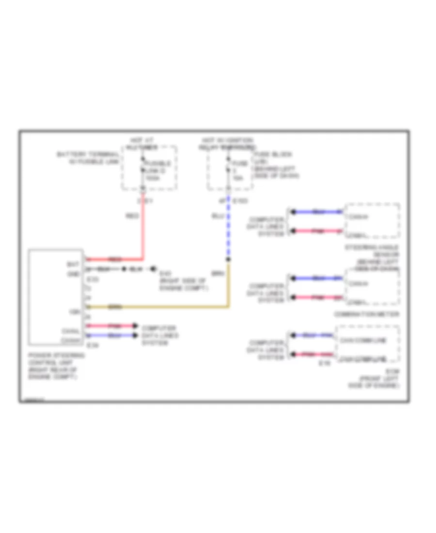
ELECTRONIC POWER STEERING
Electronic Power Steering Wiring Diagram for Nissan Quest LE 2013
List of elements for Electronic Power Steering Wiring Diagram for Nissan Quest LE 2013:
- Bat
- Battery terminal w/ fusible link
- Can comm line
- Can-h
- Can-l
- Combination meter
- Computer data lines system
- E103
- E16
- E33
- E34
- E43 (right side of engine compt)
- Ecm (front left side of engine)
- Fuse 10a
- Fuse block (j/b) (behind left side of dash)
- Fusible link d 100a
- Gnd
- Hot at all times
- Hot w/ ignition relay energized
- Ign
- Pnk
- Power steering control unit (right rear of engine compt)
- Red
- Steering angle sensor (behind left side of dash)
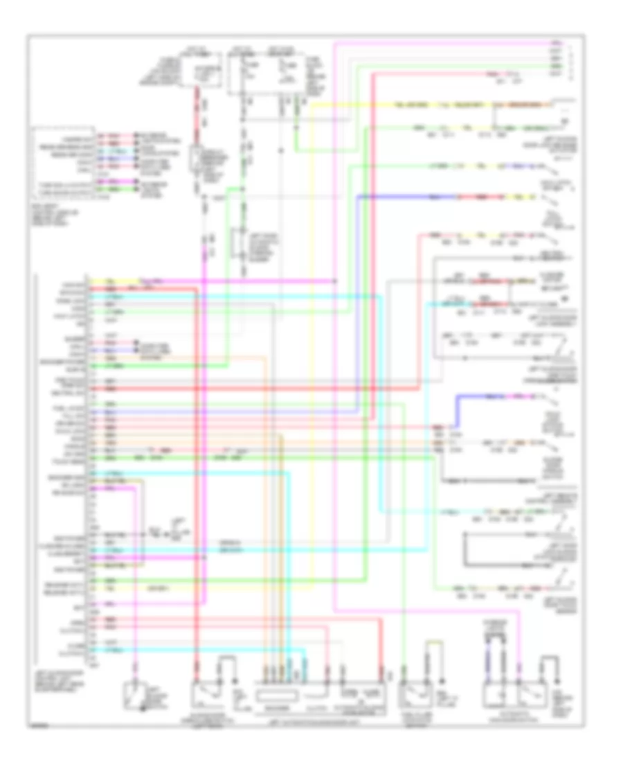
ENGINE PERFORMANCE
3.5L
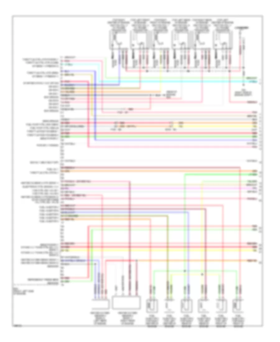
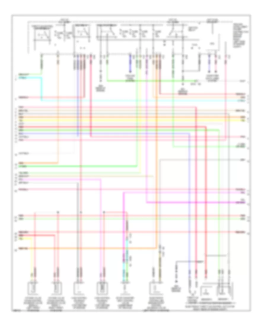
3.5L, Engine Performance Wiring Diagram (1 of 4) for Nissan Quest LE 2013
List of elements for 3.5L, Engine Performance Wiring Diagram (1 of 4) for Nissan Quest LE 2013:
- (rear of engine) e38
- (top left center of engine) ignition coil 4 (w/ power transistor)
- (top left front of engine) ignition coil 2 (w/ power transistor)
- (top left rear of engine) ignition coil 6 (w/ power transistor)
- (top right center of engine) ignition coil 3 (w/ power transistor)
- (top right front of engine) ignition coil 1 (w/ power transistor)
- (top right rear of engine) ignition coil 5 (w/ power transistor)
- A/f sens 1 htr(bank 1)
- A/f sens 1 htr(bank 2)
- Condenser
- E104 b4
- Ecm (front left side of engine)
- Ecm ground
- Ecm rly (self shut-off)
- Electronic ctrl eng sol vlv
- F121 e7
- F123 e6
- F83 (right side of engine compt)
- Fuel inj 1
- Fuel injector 1 (top right front of engine)
- Fuel injector 2
- Fuel injector 2 (top left front of engine)
- Fuel injector 3
- Fuel injector 3 (top right center of engine)
- Fuel injector 4
- Fuel injector 4 (top left center of engine)
- Fuel injector 5
- Fuel injector 5 (top right rear of engine)
- Fuel injector 6
- Fuel injector 6 (top left rear of engine)
- Fuel pump ctrl mod check
- Fuel pump ctrl module
- Heated o2 sens 2 htr 1(bank 1)
- Heated o2 sens 2 htr 2(bank 2) evap canister purge vol ctrl sol valve
- Heated oxygen sens 2 (bank 1)
- Heated oxygen sens 2 (bank 2)
- Heated oxygen sensor 2 (bank 1) (right rear of engine)
- Heated oxygen sensor 2 (bank 2) (left rear of engine)
- Ign sig 1
- Ign sig 2
- Ign sig 3
- Ign sig 4
- Ign sig 5
- Ign sig 6
- Intake vlv timing ctrl sol vlv (bank 2)
- Nca
- Plug spark
- Pnk
- Pwr sply for ecm
- Red
- Refrigerant press sens
- Sens gnd
- Sens ground
- Sens pwr sply
- Sens pwr sply intake vlv timing ctrl sol vlv (bank 1)
- Spark plug
- Starter mtr rly cut off sig
- Throttle ctrl mtr (close)
- Throttle ctrl mtr (open)
- Throttle ctrl mtr pwr sply
- Throttle ctrl mtr rly
- Throttle position sens 1
- Throttle position sens 2
- Vias ctrl sol valve 1
- Vias ctrl sol valve 2
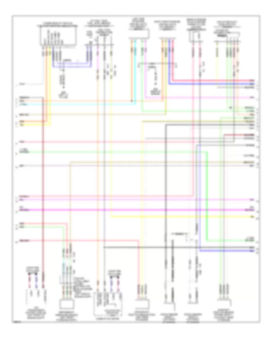
3.5L, Engine Performance Wiring Diagram (2 of 4) for Nissan Quest LE 2013
List of elements for 3.5L, Engine Performance Wiring Diagram (2 of 4) for Nissan Quest LE 2013:
- (or red)
- Close
- Computer data lines system
- Cooling fans system
- Cpu
- E10
- E104 b4
- E11
- E21 (rear of engine)
- E38 (rear of engine)
- E6 f123
- Ecm relay
- Electronic controlled engine mount control solenoid valve (left front of engine)
- Electronic throttle control actuator (right rear of engine compt)
- Evap canister vent control valve (under rear of vehicle)
- F12
- F121 e7
- Fuel pump relay
- Fuse 10a
- Fuse 15a
- Hot at all times
- Hot in on or start
- Ignition relay
- Intake valve timing control solenoid valve (bank 1) (right front of engine)
- Intake valve timing control solenoid valve (bank 2) (left front of engine)
- Ipdm e/r (intelligent power distribution module engine room) (left side of engine compt)
- Nca
- Open
- Pnk
- Red
- Sensor 1
- Sensor 2
- Throttle control motor
- Throttle control motor relay
- Throttle position sensor
- Vias control solenoid valve 1 (top center of engine)
- Vias control solenoid valve 2 (top center of engine)
3.5L, Engine Performance Wiring Diagram (3 of 4) for Nissan Quest LE 2013
List of elements for 3.5L, Engine Performance Wiring Diagram (3 of 4) for Nissan Quest LE 2013:
- (air intake duct) mass air flow sensor
- (at fuel tank) fuel level sensor unit & fuel pump
- (left side of engine) air/fuel ratio (a/f) sensor 1 (bank 2)
- (rear of engine) evap canister purge volume control solenoid valve
- (right side of engine) air/fuel ratio (a/f) sensor 1 (bank 1)
- (under rear of vehicle) fuel pump control module (fpcm)
- B11 m77
- B26 (left "c" pillar)
- B4 e104
- Batt
- Camshaft position sensor (phase) (bank 1) (top right rear of engine)
- Can-h
- Can-l
- Combination meter
- Computer data lines system
- Crankshaft position sensor (pos) (left rear of engine)
- Diag out sig
- E10
- E38 (rear of engine)
- F121 e7
- F123 e6
- F78 f200
- Fpc in sig
- Fuel level
- Fuel pump
- Fuel pump +
- Fuel pump -
- Fuel tank temperature sensor
- Gnd
- Intake air temperature sensor
- Ipdm e/r (intelligent power distribution e346 module engine room) (left side of engine compt)
- Knock sensor (bank 1) (top front of engine)
- Knock sensor (bank 2) (top front of engine)
- Malfunction indicator lamp
- Nca
- Pnk
- Red
- Refrigerant pressure sensor (left front of engine compt)
- Sens gnd
- Shield
- Strt rly
- Tcm (transmission control module) (left front of engine compt)
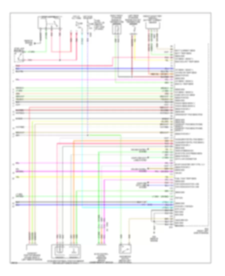
3.5L, Engine Performance Wiring Diagram (4 of 4) for Nissan Quest LE 2013
List of elements for 3.5L, Engine Performance Wiring Diagram (4 of 4) for Nissan Quest LE 2013:
- (left rear of engine) engine coolant temperature sensor
- (or red)
- (rear of engine) e21
- (right front of engine) engine oil temperature sensor
- A/f sens 1 (bank 1)
- A/f sens 1 (bank 2)
- Accelerator pdl pos sens 1
- Accelerator pdl pos sens 2
- Accelerator pedal position sensor (behind left side of dash)
- Ascd brake switch (behind left side of dash)
- Ascd brk sw
- Ascd steering sw
- Batt current sens
- Batt temp sens
- Camshaft position sensor (phase) (bank 2) (left rear of engine)
- Can communication line
- Computer data lines system
- Crankshaft pos sens (pos)
- Cruise control system
- Data link connector
- E103
- E104 b4
- E105
- E16
- E38 (rear of engine)
- Ecm (front left side of engine)
- Ecm gnd
- Eng coolant temp sens
- Eng oil temp sens
- Evap canister vent ctrl vlv
- Evap control system pressure sensor (under rear of vehicle)
- Evap ctrl sys press sens
- Fuel tank temp sens
- Fuse 10a
- Fuse block j/b (behind left side of dash)
- Hot at all times
- Hot in on or start
- Ign sw
- Intake air temp sens
- Knock sens (bank 1)
- Knock sens (bank 2)
- M11
- Mass air flow sens
- Pnk
- Pnp sig
- Pwr sply for ecm
- Red
- Sens gnd
- Sens gnd camshaft pos sens (phase) (bank 2) camshaft pos sens (phase) (bank 1)
- Sens pwr sig
- Sens pwr sply
- Sensor 1
- Sensor 2
- Shield
- Stop lamp relay
- Stop lamp switch
- Stp lp sw
EXTERIOR LIGHTS
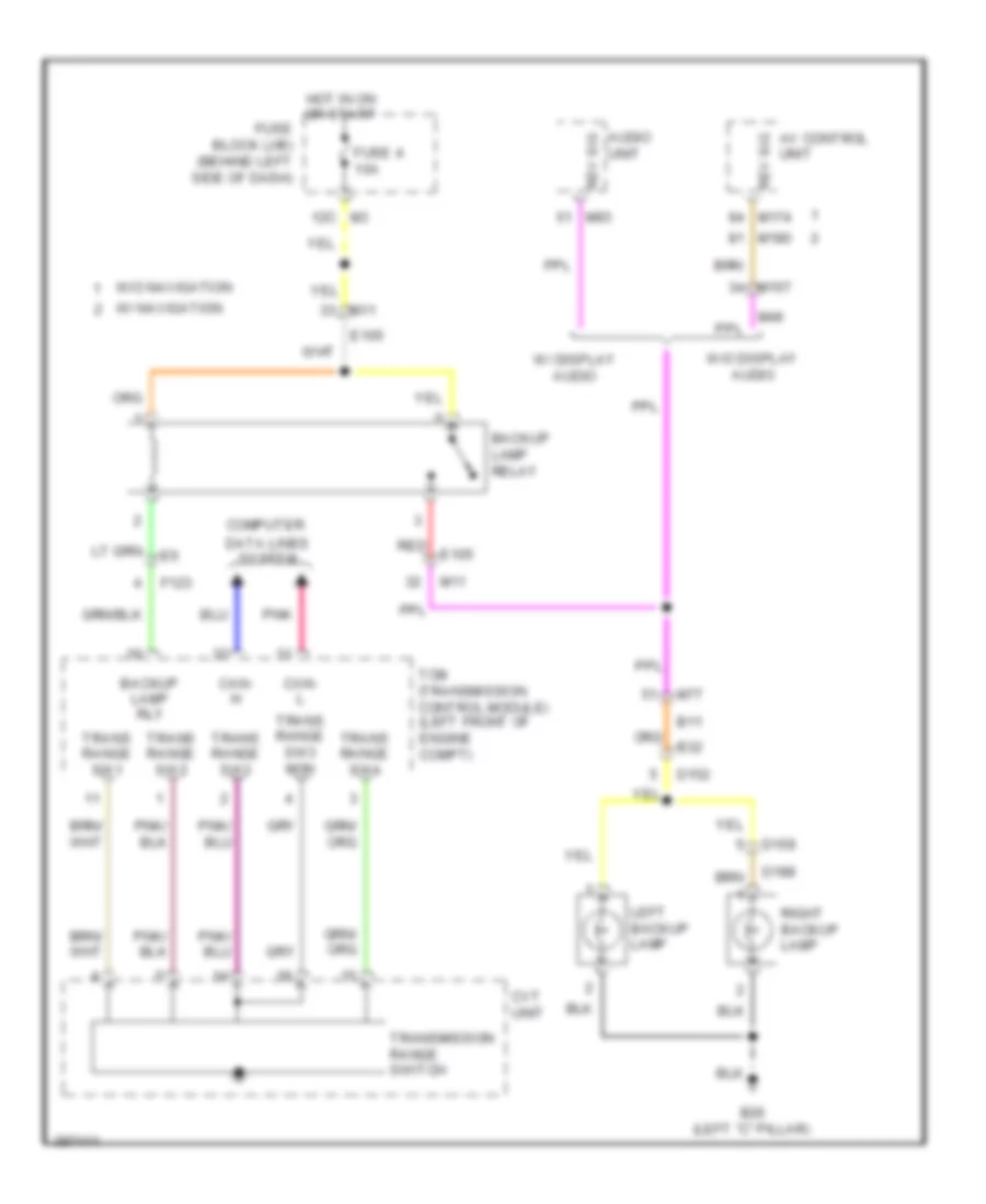
Backup Lamps Wiring Diagram for Nissan Quest LE 2013
List of elements for Backup Lamps Wiring Diagram for Nissan Quest LE 2013:
- Audio unit
- Av control unit
- B11
- B26 (left "c" pillar)
- B32
- Backup lamp relay
- Backup lamp rly
- Can- h
- Can- l
- Computer
- Cvt unit
- D152
- D159
- D188
- Data lines system
- E105
- F123
- Fuse 4 10a
- Fuse block (j/b) (behind left side of dash)
- Hot in on or start
- Left backup lamp
- M11
- M157
- M174
- M180
- M3 12c
- M46
- M77
- M93
- Pnk
- Red e105
- Rev sig
- Right backup lamp
- Tcm (transmission control module) (left front of engine compt)
- Trans range sw1
- Trans range sw2
- Trans range sw3
- Trans range sw3 mon
- Trans range sw4
- Transmission range switch
- W/ display audio
- W/ navigation
- W/o display audio
- W/o navigation
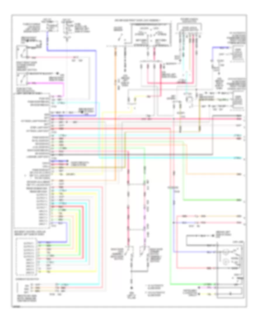
Exterior Lamps Wiring Diagram (1 of 2) for Nissan Quest LE 2013
List of elements for Exterior Lamps Wiring Diagram (1 of 2) for Nissan Quest LE 2013:
- (behind right side of dash) m43
- (or pnk)
- 12c
- Bat
- Bcm (body control module) (behind left side of dash)
- Buzzer
- Can-h
- Can-l
- Combination meter
- Combination switch
- Computer data lines system
- D21
- D21 m20
- D41
- Driver side door mirror (at mirror)
- E103
- E105
- E21 (rear of engine)
- E310 (front right of engine compt)
- E339
- Fuse & fusible link block (left side of engine compt)
- Fuse 10a
- Fuse block (j/b) (behind left side of dash)
- Fusible link l 40a
- Gnd
- Hazard sw
- Hazard switch
- Hot at all times
- Hot in on or start
- Ign sig
- Input 1
- Input 2
- Input 3
- Input 4
- Input 5
- Interior lights system
- Left front combination lamp
- Left front side marker lamp
- Lh turn sig
- M11
- M121
- M123
- M18
- M20
- M35 (behind right side of dash)
- M43 (behind right side of dash)
- M76 (behind left side of dash)
- Output 1
- Output 2
- Output 3
- Output 4
- Output 5
- Parking
- Passenger side door mirror (at mirror)
- Pnk
- Red
- Rh turn sig
- Stop lamp relay
- Stop lamp switch
- Tail lamp ind
- Turn ind
- Turn signal
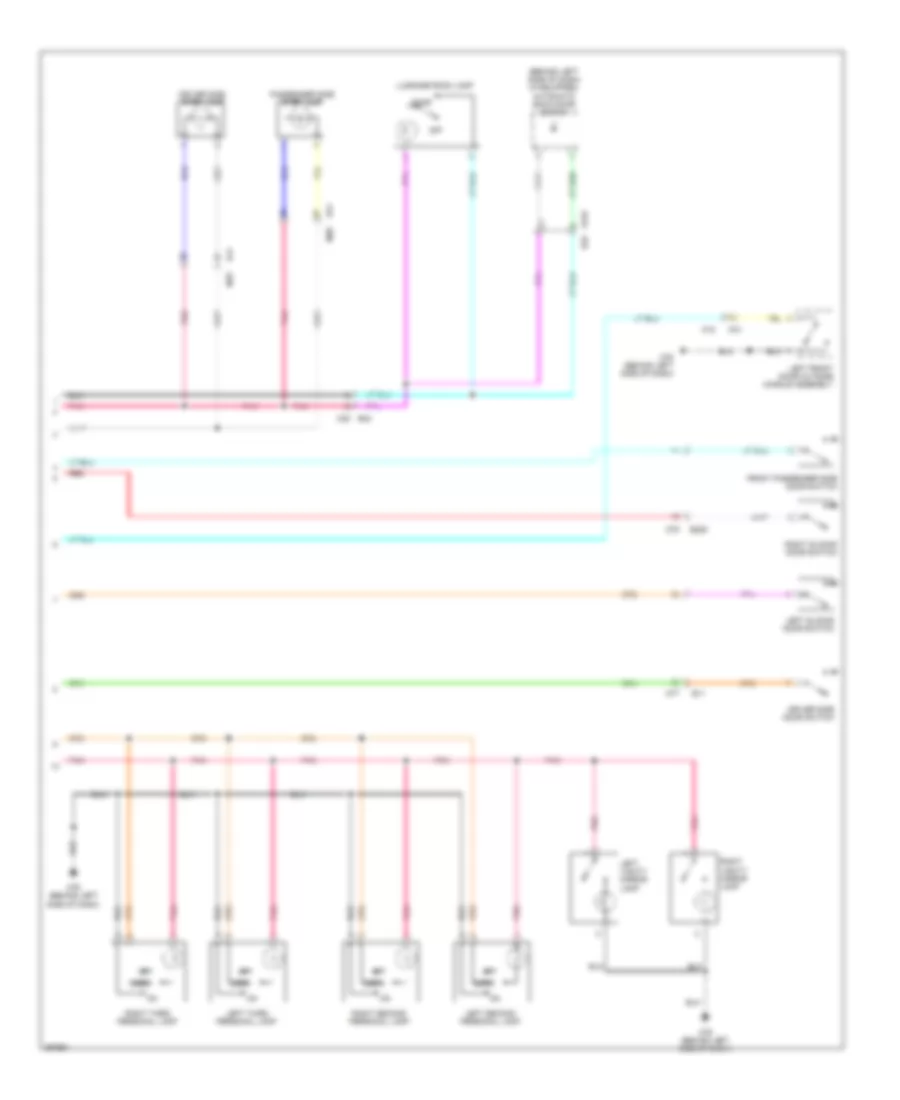
Exterior Lamps Wiring Diagram (2 of 2) for Nissan Quest LE 2013
List of elements for Exterior Lamps Wiring Diagram (2 of 2) for Nissan Quest LE 2013:
- B208 (right "c" pillar)
- B26 (left "c" pillar)
- B32
- Battery terminal w/ fusible link
- Computer data lines system
- Cpu
- D152
- D159
- D188
- E10
- E105
- E11
- E21 (rear of engine)
- E309 (front left of engine compt)
- E339
- E346
- Fuse 10a
- Fuse 15a
- Fusible link c 60a
- High-mounted stop lamp
- Hot at all times
- Ipdm e/r (intelligent power distribution module engine room) (left side of engine compt)
- Left license plate lamp
- Left rear combination lamp
- M11
- M70 b216
- M77 b11
- Parking
- Pnk
- Right front combination lamp
- Right front side marker lamp
- Right license plate lamp
- Right rear combination lamp
- Signal turn
- Stop
- Tail lamp relay
- Turn signal
GROUND DISTRIBUTION
Ground Distribution Wiring Diagram for Nissan Quest LE 2013
List of elements for Ground Distribution Wiring Diagram for Nissan Quest LE 2013:
- Abs actuator & electric unit (control unit)
- Alternator
- B15 (left "a" pillar)
- B207 (right "b" pillar)
- B208 (right "c" pillar)
- B243 (right "c" pillar)
- B26 (left "c" pillar)
- Bcm (body control module), passenger side front power window switch, automatic drive positioner control unit, front power socket & selective unlock relay
- Bose amplifier & right sliding door control unit
- Cooling fan motor 2, exhaust gas/outside odor detecting sensor, right front combination lamp, right low headlamp, right high headlamp, right front side marker lamp, right front fog lamp, washer level switch & daytime running light relay
- Cooling fan motor 2, left front combination lamp, left low headlamp, left high headlamp, left front side marker lamp & left front fog lamp
- Cvt shift selector, air bag diagnosis sensor unit, passenger air bag off indicator, rear blower relay, intake door motor, passenger side heated seat switch, push button ignition switch, driver side heated seat switch, nats antenna amp, dongle unit, passenger side front power window switch, hazard switch, right front door ouside handle assembly (request switch), glove box lamp, a/c auto amp, tel adapter unit, audio unit, multi-function switch, front display unit, av control unit, around view monitor control unit, ac 120v outlet main switch, front mode door motor, front air mix door motor (manual a/c), passenger side door mirror, right side radar shield, bsw control module, a/c amp (rear defogger switch), left front air mix door motor (automatic a/c) & right front air mix door motor (automatic a/c)
- Driver side front seat belt buckle open/close switch, driver side front seat lumbar support switch, driver seat control unit, left rear sliding door open/close switch, left sliding door power window switch, driver side power seat switch, driver side front lifting motor, driver side rear lifting motor, driver side reclining motor, driver side sliding motor, driver side seat cushion heater & auxiliary input jacks shield
- E21 (rear of engine)
- E307 (front right of engine compt)
- E309 (front left of engine compt)
- E310 (front right of engine compt)
- E38 (rear of engine)
- E42 (behind left end of dash)
- E43 (right side of engine compt)
- Engine control module (ecm), compressor, air fuel ratio (a/f) sensor 1 (bank 2) shield, electric throttle control actuator shield, ipdm e/r (intelligent power distribution module engine room) & cooling fan relay 2
- F83 (right side of engine compt)
- F84 (right side of engine compt)
- Fuel pump control module, back door control unit, automatic back door close switch, automatic back door control module, high mounted stop lamp, left backup lamp, right backup lamp, left license plate lamp, right license plate lamp, fuel filler lid status switch, left rear combination lamp, back door lock assembly, back door opener switch assembly, rear wiper motor, rear window defogger, satellite radio tuner, left third seat fold switch, luggage room power socket, left side radar, right side radar, seat back power return control unit, right seat back lock release actuator, left seat back lock release actuator, left sliding door control unit & fuel pump control module shield
- Ignition coils 1, 2, 3, 4, 5, 6 (w/ power transistor) & condenser
- M35 (behind right side of dash)
- M43 (behind right side of dash)
- M76 (behind left side of dash)
- Occupant detection system belt control unit, passenger side front seat belt buckle switch, right rear sliding door open/close switch, passenger side front power seat switch, inside key antenna (luggage room) shield & passenger side seat cushion heater
- Power steering control module
- Rear right sliding door control unit shield mode door motor, rear blower motor, rear air mix door motor, right third seat fold switch, right sliding door control unit, right sliding door power window switch & right rear combination lamp
- Steering angle sensor, data link connector, vdc off switch, combination meter, rear a/c control, ionizer, front blower motor, door mirror remote control switch, seat memory switch, automatic main door switch, automatic back door switch, driver side front door lock assembly, rear sunroof switch, door mirror remote control switch, auto anti-dazzling inside mirror, map lamp, power window main switch, rear display unit, combination switch, driver side door mirror, bsw switch, inverter unit, left side radar shield, driver side front door lock assembly, front sunroof switch, front sunroof motor assembly, rear sunroof motor assembly, left vanity mirror lamp, right vanity mirror lamp, left second personal lamp, right second personal lamp, left third personal lamp, right third personal lamp, fuse block (j/b), left front door outside handle assembly (request switch) & inside key antenna (luggage room) shield
- Stop lamp relay, brake fluid level switch, ipdm e/r (intelligent power distribution module engine room), daytime running light relay, front wiper motor, brake fluid level switch cooling fan relay 3 & transmission control module (tcm)
HEADLIGHTS
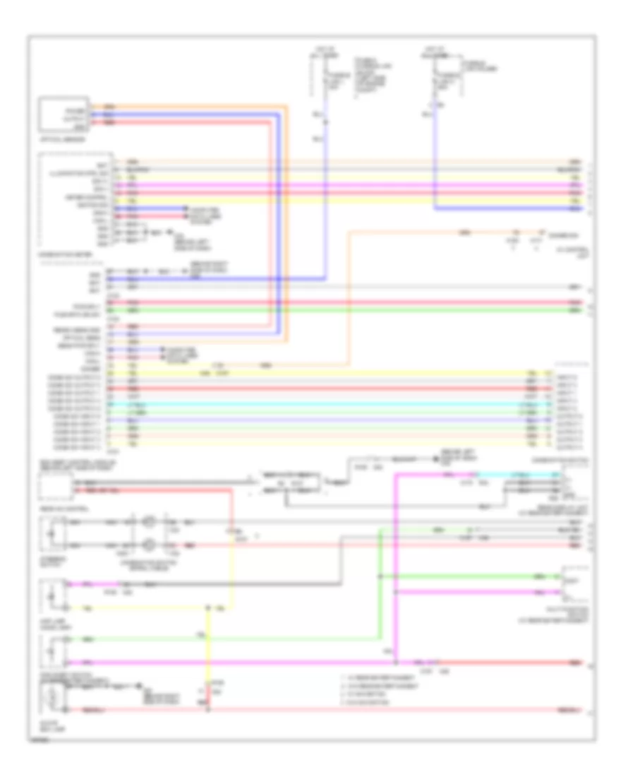
Headlights Wiring Diagram (1 of 2) for Nissan Quest LE 2013
List of elements for Headlights Wiring Diagram (1 of 2) for Nissan Quest LE 2013:
- (or red)
- 12c
- B11
- B225
- B26 (left "c" pillar)
- B32
- Back door lock assembly (back door switch)
- Bat (f/l)
- Bat (fuse)
- Bk door sw
- Body control module (bcm) (behind left side of dash)
- Can-h
- Can-l
- Combi sw input 1
- Combi sw input 2
- Combi sw input 3
- Combi sw input 4
- Combi sw input 5
- Combi sw output 1
- Combi sw output 2
- Combi sw output 3
- Combi sw output 4
- Combi sw output 5
- Combination switch
- Computer data lines system
- D152
- D159
- D188
- Driver door sw
- Driver side door switch
- Front passenger side door switch
- Fuse & fusible link block (left side of engine compt)
- Fuse 10a
- Fuse block (j/b) (behind left side of dash)
- Fusible link l 40a
- Gnd
- Hot at all times
- Hot in on or start
- Input 1
- Input 2
- Input 3
- Input 4
- Input 5
- Left sl door sw
- Left sliding door switch
- M121
- M122
- M123
- M35 (behind right side of dash)
- M77
- M77 b11
- M79
- Optical sensor
- Output
- Output 1
- Output 2
- Output 3
- Output 4
- Output 5
- Passenger door sw
- Pnk
- Power
- Receive/sensor gnd
- Red
- Right sl door sw
- Right sliding door switch
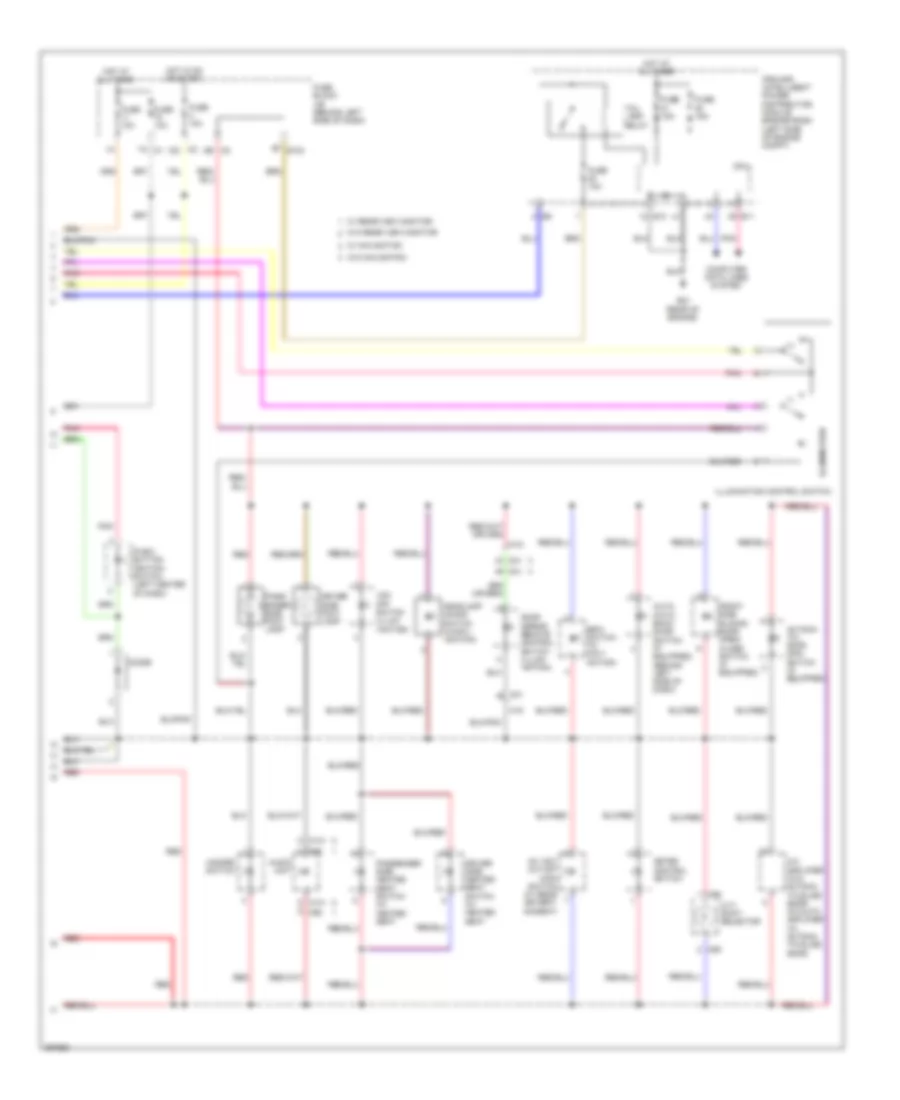
Headlights Wiring Diagram (2 of 2) for Nissan Quest LE 2013
List of elements for Headlights Wiring Diagram (2 of 2) for Nissan Quest LE 2013:
- (front right of engine compt) e310
- Av control unit
- Batt
- Battery terminal w/ fusible link
- Can-h
- Can-l
- Combination meter
- Computer data lines system
- Cpu
- Daytime running light relay (w/ drl)
- E10
- E105
- E11
- E21 (rear of engine)
- E309 (front left of engine compt)
- E310 (front right of engine compt)
- E339
- E345
- E346
- Front fog lamp relay
- Fuse 10a
- Fuse 15a
- Fusible link c 60a
- Ground
- Headlamp high relay
- Headlamp low relay
- Hid cont
- High beam ind
- Hot at all times
- Ignition
- Ipdm e/r (intelligent power distribution module engine room) (left side of engine compt)
- Left front fog lamp
- Left high headlamp
- Left low headlamp
- M11
- M157
- M174
- M180
- M46
- M76 (behind left side of dash)
- Parking brake
- Parking brake switch
- Pnk
- Red
- Right front fog lamp
- Right high headlamp
- Right low headlamp
- W/ drl
- W/ navigation
- W/ xenon headlamp
- W/o drl
- W/o navigation
- W/o xenon headlamp
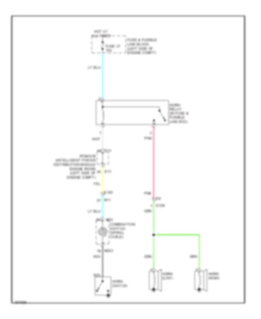
HORN
Horn Wiring Diagram for Nissan Quest LE 2013
List of elements for Horn Wiring Diagram for Nissan Quest LE 2013:
- Combination switch (spiral cable)
- E105
- E11
- E339
- Fuse & fusible link block (left side of engine compt)
- Fuse 37 15a
- Horn (high)
- Horn (low)
- Horn relay (in fuse & fusible link box)
- Horn switch
- Hot at all times
- Ipdm e/r (intelligent power distribution module engine room) (left side of engine compt)
- M11
- M303
- M33
- Nca
- Pnk
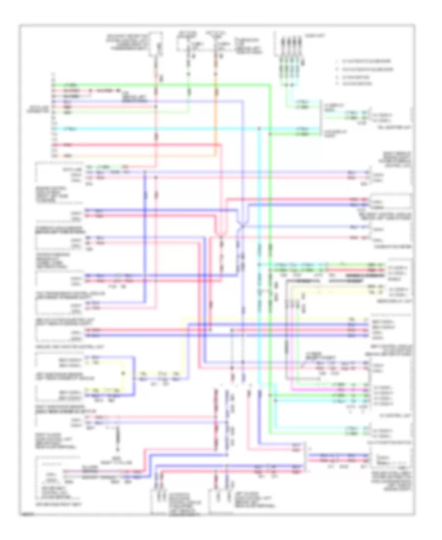
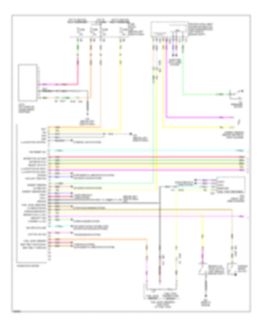
INSTRUMENT CLUSTER
Instrument Cluster Wiring Diagram (1 of 2) for Nissan Quest LE 2013
List of elements for Instrument Cluster Wiring Diagram (1 of 2) for Nissan Quest LE 2013:
- (behind left side of dash) m76
- 12c
- A/c rec sig
- Air bag
- Air conditioning system
- Air conditioning, power tops, navigation & sound systems
- Alternator sig
- Ambient sensor
- Ambient sensor (behind center of front bumper)
- Ambient sensor gnd
- Auto anti-dazzling inside mirror (compass)
- B11
- Bat
- Brake fluid level switch (left rear of engine compt)
- Brake fluid lvl sw
- Can-h
- Can-l
- Combination meter
- Computer data lines system
- Coolant temp sig
- Cpu
- E10
- E104
- E105
- E11
- E16
- E21 (rear of engine)
- E346
- Ecm (front left side of engine)
- Enter switch
- F12
- Fuel level sens gnd
- Fuel level sensor
- Fuel level sensor & fuel pump (at fuel tank)
- Fuel tank temp sens
- Fuel tank temperature sensor
- Fuse 10a
- Fuse 15a
- Fuse block (j/b) (behind left side of dash)
- Gnd
- Ground
- Hot at all times
- Hot w/ ignition relay energized
- Ign
- Illumination control
- Illumination sw sig(+)
- Illumination sw sig(-)
- Interior lights system
- Ipdm e/r (intelligent power distribution module engine room) (left side of engine compt)
- M11
- M11 e105
- M22
- M76 (behind left side of dash)
- M77
- Meter ctrl sw gnd
- O/d ctrl sw sig
- Oil pressure switch
- Parking brake sw
- Parking brake switch
- Pnk
- R106
- R107
- Red
- Seat belt buckle sw
- Seat belt warn sig
- Security sig
- Select switch
- Sens gnd
- Starting/charging system
- Transmissions system
- Trip reset sw
- Veh spd (8-pulse)
- Washer lvl sw
- Wiper/washer system
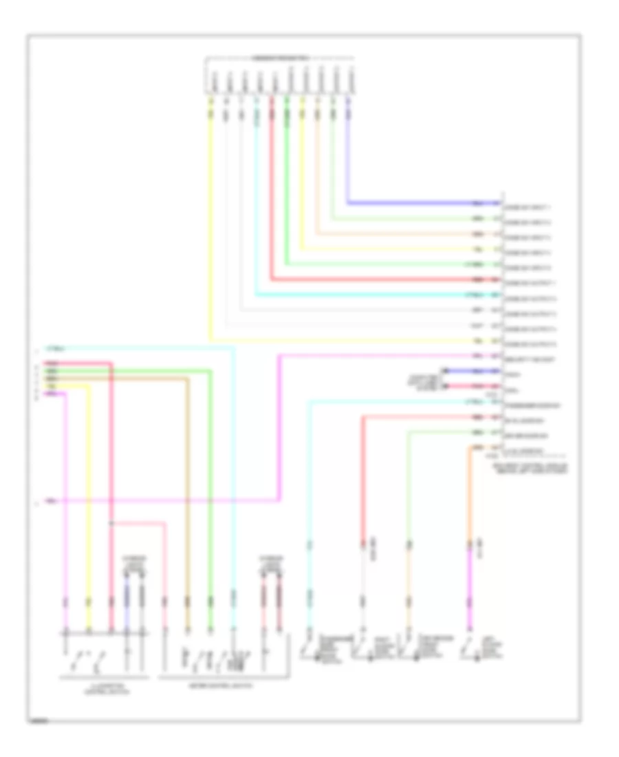
Instrument Cluster Wiring Diagram (2 of 2) for Nissan Quest LE 2013
List of elements for Instrument Cluster Wiring Diagram (2 of 2) for Nissan Quest LE 2013:
- Bcm (body control module) (behind left side of dash)
- Can-h
- Can-l
- Combi sw input 1
- Combi sw input 2
- Combi sw input 3
- Combi sw input 4
- Combi sw input 5
- Combi sw output 1
- Combi sw output 2
- Combi sw output 3
- Combi sw output 4
- Combi sw output 5
- Combination switch
- Computer data lines system
- Driver door sw
- Driver side front door switch
- Enter
- Illumination control switch
- Input 1
- Input 2
- Input 3
- Input 4
- Input 5
- Interior lights system
- Left sliding door switch
- Lh sl door sw
- M121
- M122
- M77 b11
- M79 b225
- Meter control switch
- Output 1
- Output 2
- Output 3
- Output 4
- Output 5
- Passenger door sw
- Passenger side front door switch
- Pnk
- Red
- Rh sl door sw
- Right sliding door switch
- Security ind cont
- Select
- Switch reset trip
INTERIOR LIGHTS
Courtesy Lamps Wiring Diagram (1 of 2) for Nissan Quest LE 2013
List of elements for Courtesy Lamps Wiring Diagram (1 of 2) for Nissan Quest LE 2013:
- (behind left side of dash) m76
- (behind right side of dash) m35
- (behind right side of dash) m43
- (w/ automatic slide door) passenger side front power window switch
- (w/o automatic slide door) passenger side front power window switch
- B11
- B26 (left "c" pillar)
- B32
- Back door lock assembly (back door switch)
- Back door opener switch assembly (request switch)
- Back door req sw
- Bat
- Bcm (body control module) (behind left side of dash)
- Between full stroke & n
- Bk door sw
- Can-h
- Can-l
- Combination switch
- Computer data lines system
- D152
- D159
- D188
- D21
- D21 m20
- D41
- D41 m18
- Door
- Door key cylinder switch
- Door lock & unlock switch
- Dr door req sw
- Dr door sw
- Dr door unlk sens
- Dr lk & un lk sw
- Driver side front door lock assembly
- Full stroke
- Fuse & fusible link block (left side of engine compt)
- Fuse 10a
- Fuse block (j/b) (behind left side of dash)
- Fusible link l 40a
- Gnd
- Hot at all times
- Input 1
- Input 2
- Input 3
- Input 4
- Input 5
- Instrument illumination circuit
- Int room lamp cont
- Int room lamp pwr sply
- Key cyl lock sw pw sw comm
- Key cyl unlock sw
- Lh sl door sw
- Lock
- Luggage lamp cont
- M121
- M122
- M123
- M124
- M18
- M20
- M22
- M35 (behind right side of dash)
- M43 (behind right side of dash)
- M76 (behind left side of dash)
- M77
- Map lamp
- Off
- Output 1
- Output 2
- Output 3
- Output 4
- Output 5
- Pass door req sw
- Pass door sw
- Pnk
- Power window main switch
- Push button ignition switch (left center of dash)
- Push sw
- R106
- R107
- Receive/sens gnd
- Receiver comm
- Red
- Remote keyless entry receiver (center of roof)
- Rh sl door sw
- Right front door outside handle assembly (request switch)
- Sig
- Slide door
- Step lamp cont
- Unlock
- Unlock sensor
- W/ automatic
- W/o automatic
Courtesy Lamps Wiring Diagram (2 of 2) for Nissan Quest LE 2013
List of elements for Courtesy Lamps Wiring Diagram (2 of 2) for Nissan Quest LE 2013:
- (behind left side of dash) (if equipped) automatic back door switch
- B11
- B225
- D152 b32
- D21
- D41
- Door
- Driver side door switch
- Driver side step lamp
- Front passenger side door switch
- Left front door outside handle assembly
- Left second personal lamp
- Left sliding door switch
- Left third personal lamp
- Left vanity mirror lamp
- Luggage room lamp
- M18
- M20
- M38 b42
- M76 (behind left side of dash)
- M77
- M79
- Off
- Passenger side step lamp
- Pnk
- Red
- Right second personal lamp
- Right sliding door switch
- Right third personal lamp
- Right vanity mirror lamp
Instrument Illumination Wiring Diagram (1 of 2) for Nissan Quest LE 2013
List of elements for Instrument Illumination Wiring Diagram (1 of 2) for Nissan Quest LE 2013:
- (behind left side of dash) m76
- (behind right side of dash) m35
- Av control unit
- Bat
- Bcm (body control module) (behind left side of dash)
- Can-h
- Can-l
- Combi sw input 1
- Combi sw input 2
- Combi sw input 3
- Combi sw input 4
- Combi sw input 5
- Combi sw output 1
- Combi sw output 2
- Combi sw output 3
- Combi sw output 4
- Combi sw output 5
- Combination meter
- Combination switch
- Combination switch (spiral cable)
- Computer data lines system
- Cont
- Dimmer
- Dimmer sig
- Disc eject switch (w/ rear entertainment)
- Fuse & fusible link block (left side of engine compt)
- Fusible link c 60a
- Fusible link holder
- Fusible link l 40a
- Glove box lamp
- Gnd
- Hot at all times
- Ignition sig
- Ill
- Illumination ctrl sig
- Input 1
- Input 2
- Input 3
- Input 4
- Input 5
- M121
- M123
- M124
- M157
- M170 r34
- M171
- M180
- M22
- M303
- M32
- M33
- M43 (behind right side of dash)
- M46
- M76 (behind left side of dash)
- Map lamp (mood lamp)
- Meter control
- Multi-function switch (w/ rear entertainment)
- Nca
- Optical sens
- Optical sensor
- Output
- Output 1
- Output 2
- Output 3
- Output 4
- Output 5
- Pnk
- Power
- Push-btn ign sw
- Pwr sply
- R106
- R107
- R36
- Rear a/c control
- Rear display unit (w/ rear entertainment)
- Receiv/sens gnd
- Red
- Sens pwr sply
- Sig (+)
- Sig (-)
- Steering switch
- W/ navigation
- W/ rear entertainment
- W/o navigation
- W/o rear entertainment
Instrument Illumination Wiring Diagram (2 of 2) for Nissan Quest LE 2013
List of elements for Instrument Illumination Wiring Diagram (2 of 2) for Nissan Quest LE 2013:
- (+)
- (-)
- 7a m1
- 9f e103
- A/c amplifier (w/o automa- tic slide door) a/c auto amplifier (w/ automa- tic slide door)
- Ac 120v outlet main switch (w/ rear entert- ainment)
- Audio unit
- Auto- matic back door switch (if equipped) (behind left side of dash)
- Automa- tic door main switch (if equipped)
- Bsw switch (w/ navi- gation)
- Computer data lines system
- Cpu
- Cvt shift selector
- D41
- Diode
- Door mirror remote control switch (illumi- -nation)
- Driver side foot lamp
- Driver side heated seat switch (w/ heated seat
- E10
- E11
- E21 (rear of engine)
- Front side sliding door open/ close switch (if equipped)
- Fuse 10a
- Fuse 15a
- Fuse block j/b (behind left side of dash)
- Hazard switch
- Headlamp aiming switch (w/nav- -igation)
- Hot at all times
- Hot in on or start
- Illumination
- Illumination control switch
- Ipdm e/r (intelligent power distribution module engine room) (left side of engine compt)
- M141
- M18
- M2 8b
- M3 12c
- M85
- M92
- Meter control switch
- Pass- enger side foot lamp
- Passenger side heated seat switch (w/ heated seat
- Pnk
- Push- button ignition switch (left center of dash)
- Red
- Tail lamp relay
- Vdc off switch (illum- -ination)
- W/ navigation
- W/ rear view monitor
- W/o navigation
- W/o rear view monitor
MEMORY SYSTEMS
Memory Systems Wiring Diagram (1 of 3) for Nissan Quest LE 2013
List of elements for Memory Systems Wiring Diagram (1 of 3) for Nissan Quest LE 2013:
- (behind right side of dash) m43
- Automatic drive positioner control unit (behind right end of dash)
- B11
- Batt
- Camera
- Circuit breaker (behind left side of dash)
- D21
- D41
- Defogger system
- Down ward
- Downward
- Driver side door mirror (at mirror)
- E105
- Exterior
- Fuse & fusible link block (left side of engine compt)
- Fusible link l 40a
- Gnd
- Hot at all times
- Left
- Left bsw indicator
- Leftward
- Lh mir mtr down right
- Lh mir mtr left
- Lh mir mtr up
- Lh mir sens lh & rh
- Lh mir sens up down
- Lights system
- M104
- M11
- M18
- M20
- M35 (behind right side of dash)
- M75
- M76 (behind left side of dash)
- M77
- Navigation system
- Nca
- Passenger side door mirror (at mirror)
- Pnk
- Red
- Rh mir mtr down rh
- Rh mir mtr left
- Rh mir mtr up
- Rh mir sens lh & rh
- Rh mir sens up down
- Right
- Right bsw indicator
- Rightward
- Rx/tx
- Select lh
- Select rh
- Sens gnd
- Sens power
- System defogger
- System lights exterior
- System navigation
- Turn signal
- Up ward
- Upward
Memory Systems Wiring Diagram (2 of 3) for Nissan Quest LE 2013
List of elements for Memory Systems Wiring Diagram (2 of 3) for Nissan Quest LE 2013:
- (behind right side of dash) m35
- B11
- Bat
- Bcm (body control module) (behind left side of dash)
- Can-h
- Can-l
- Change over switch
- Computer data lines system
- Cvt shift selector (detention switch)
- D41
- Detent sw
- Door mirror remote control switch
- Driver door switch
- Drv door sw
- Fuse 10a
- Fuse block (j/b) (behind left side of dash)
- Gnd
- Hot at all times
- Ill
- Ind 2 memory
- Interior lights system
- Left
- M121
- M122
- M123
- M124
- M18
- M76 (behind left side of dash)
- M77
- Memory ind 1
- Memory switch 1
- Memory switch 2
- Mirror switch
- Off
- Pnk
- Pwr sply
- Red
- Right
- Seat memory switch
- Set switch
Memory Systems Wiring Diagram (3 of 3) for Nissan Quest LE 2013
List of elements for Memory Systems Wiring Diagram (3 of 3) for Nissan Quest LE 2013:
- B11
- B15 (left "a" pillar)
- B530
- B551
- B552
- B89
- Back
- Backward
- Computer data lines system
- Down
- Driver side front lifting motor
- Driver side power seat switch
- Driver side rear lifting motor
- Driver side reclining motor
- Driver side sliding motor
- Driver's seat control unit (under driver's seat)
- Forward
- Front lifting sensor
- Front lifting switch
- Fwd
- M77
- Pnk
- Rear lifting sensor
- Rear lifting switch
- Reclining sensor
- Reclining switch
- Red
- Sliding sensor
- Sliding switch
NAVIGATION
Blind Spot Monitoring Wiring Diagram for Nissan Quest LE 2013
List of elements for Blind Spot Monitoring Wiring Diagram for Nissan Quest LE 2013:
- (behind left side of dash) m76
- (behind right side of dash) m43
- (left "c" pillar) b26
- B11
- B26 (left "c" pillar)
- B28
- B310
- Bsw comm-h
- Bsw comm-l
- Bsw control module (behind center of dash)
- Bsw ind
- Bsw on ind
- Bsw sw
- Bsw switch
- Can-h
- Can-l
- Combination meter
- Computer data lines system
- D21
- D41
- E10
- E104
- E105
- Fuse 10a
- Gnd
- Hot w/ ignition relay energized
- Ign
- Ill
- Ind
- Interior lights system
- Ipdm e/r (intelligent power distribution module engine room) (left side of engine compt)
- Left bsw indicator
- Left door mirror (at mirror)
- Left side radar sensor (left rear corner
- M11
- M18
- M20
- M43 (behind right side of dash)
- M76 (behind left side of dash)
- M77
- Of vehicle)
- Pnk
- Right bsw indicator
- Right door mirror (at mirror)
- Right side radar sensor (right rear corner of vehicle)
- Shield
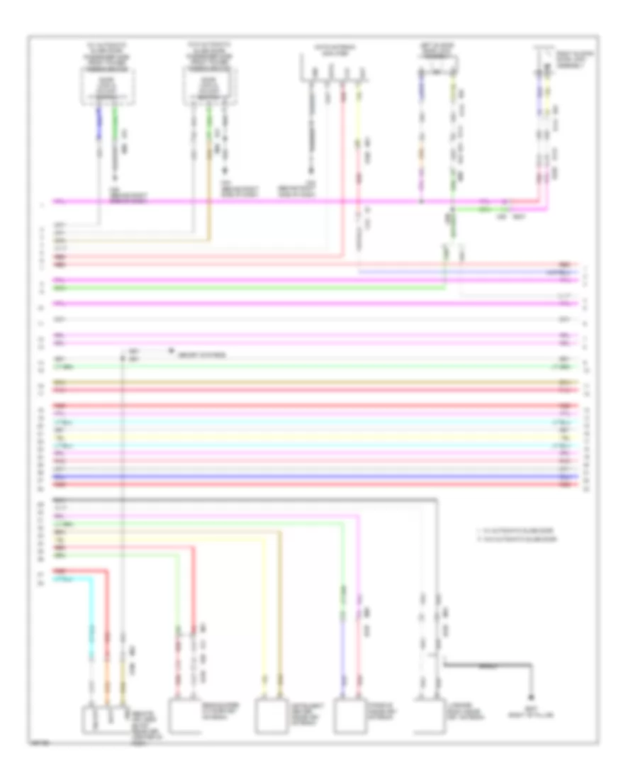
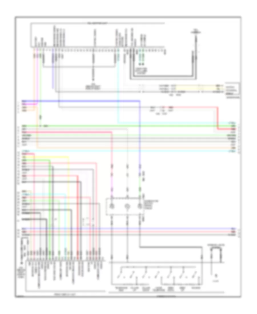
Navigation Wiring Diagram (1 of 6) for Nissan Quest LE 2013
List of elements for Navigation Wiring Diagram (1 of 6) for Nissan Quest LE 2013:
- Antenna amplifier
- Antenna signal
- Av comm (h)
- Av comm (l)
- Av control unit
- Can-h
- Can-l
- Comm (cont-disp)
- Comm (disp-cont)
- Composite image signal
- Composite image signal gnd
- Composite image sync
- Computer data lines system
- Dimmer signal
- E105
- Exterior lights system
- Fuse & fusible link block (left side of engine compt)
- Fuse 10a
- Fuse 20a
- Fuse block (j/b) (behind left side of dash)
- Glass antenna (fm sub)
- Glass antenna (main)
- Gps antenna
- Gps antenna sig
- Hot at all times
- Hot in acc or on
- Hot in on or start
- Ignition
- Interior lights system
- M11
- M157
- M180
- M351
- M353
- M356
- M357
- M361
- M362
- M364
- M365
- M366
- M367
- M368
- M369
- M370
- M46
- Microphone signal
- Microphone vcc
- Nca
- Parking brake
- Parking brake switch
- Pnk
- Red
- Reverse
- Satellite radio antenna
- Shield
- Vehicle spd sig(8-pulse)
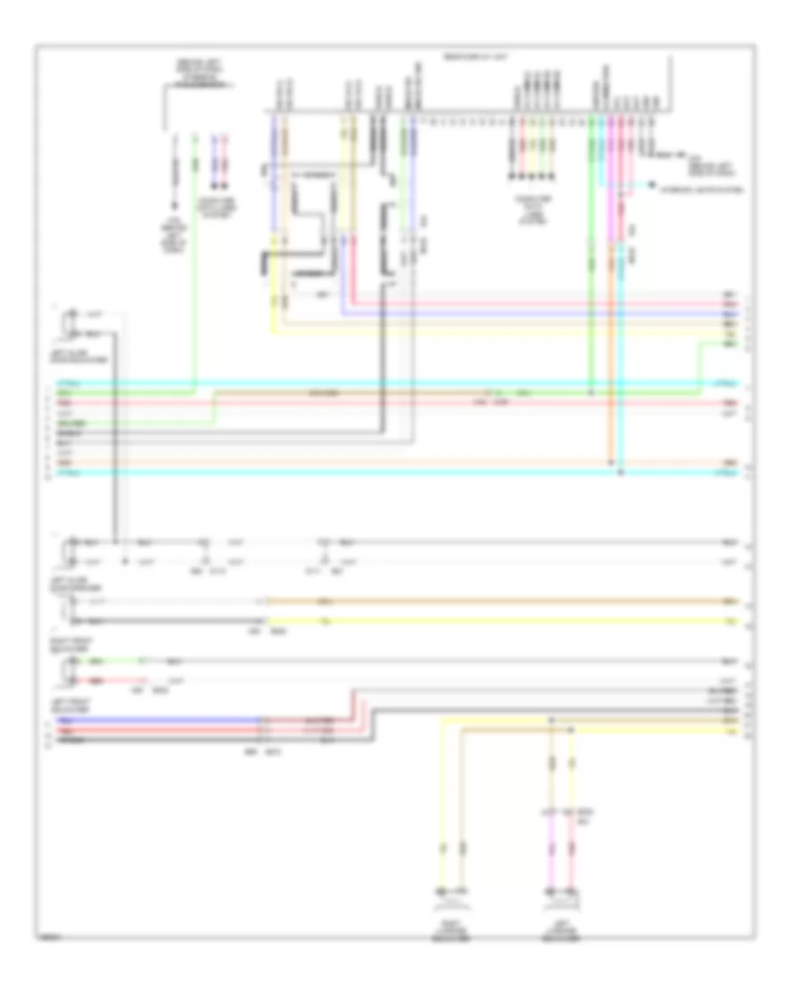
Navigation Wiring Diagram (2 of 6) for Nissan Quest LE 2013
List of elements for Navigation Wiring Diagram (2 of 6) for Nissan Quest LE 2013:
- (behind left side of dash) steering angle sensor
- Acc
- Av comm (h)
- Av comm (l)
- Back
- Battery
- Camera image signal
- Can-h
- Can-l
- Combination meter
- Combination switch (spiral cable)
- Comm (cont-disp)
- Comm (disp-cont)
- Composite image sig
- Composite sync
- Computer data lines system
- Disc eject switch
- Enter
- Front display unit
- Fuse 15a
- Fuse block (j/b) (behind left side of dash)
- Gnd
- Hot at all times
- Illum
- Image sig gnd
- Interior lights system
- M155
- M157
- M157 m46
- M303
- M33
- M358
- M43 (behind right side of dash)
- M46
- M76 (behind left side of dash)
- Menu down
- Menu up
- Multi-function switch
- Nca
- Pnk
- Red
- Shield
- Source
- Steering switch
- Telephone
- Vehicle spd sig (8-pulse)
- Voice
- Volume down
- Volume up
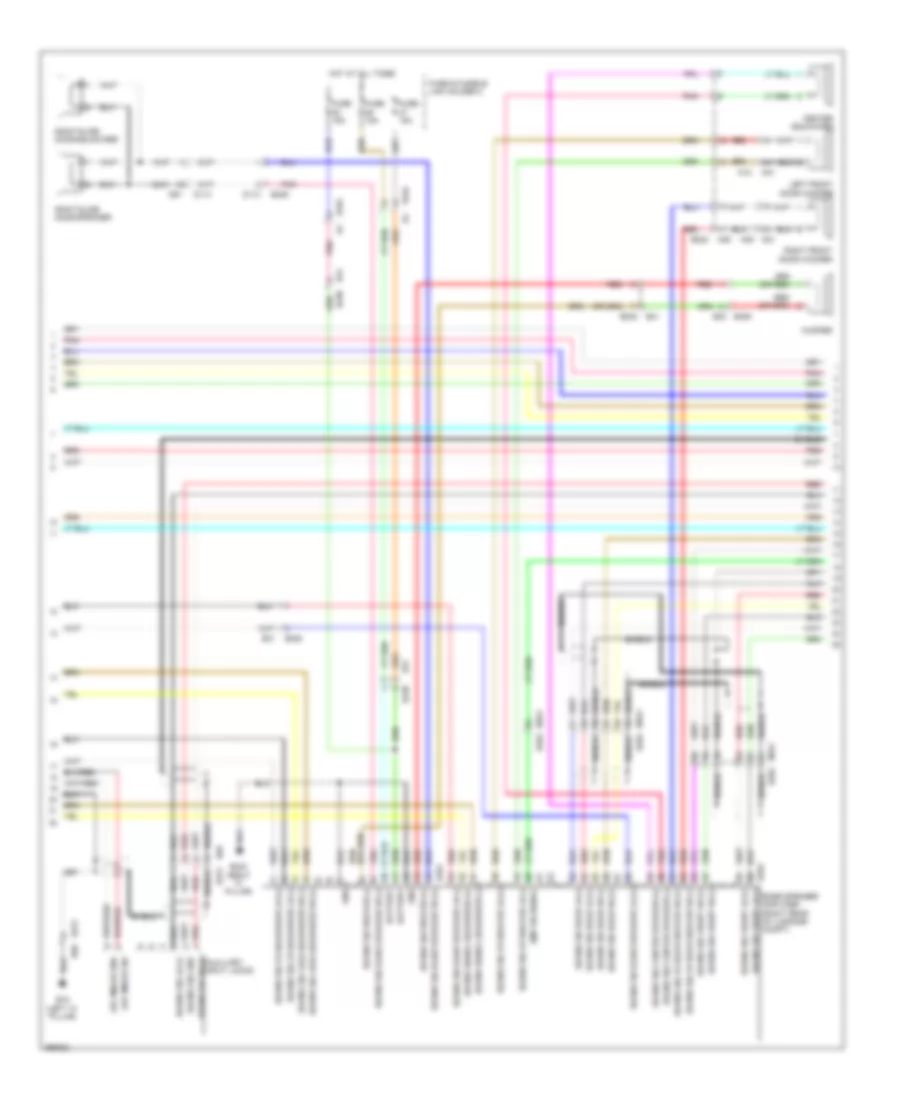
Navigation Wiring Diagram (3 of 6) for Nissan Quest LE 2013
List of elements for Navigation Wiring Diagram (3 of 6) for Nissan Quest LE 2013:
- (behind right side of dash) m43
- Acc
- Amp on signal
- Aux image signal
- Aux image signal gnd
- Av comm (h)
- Av comm (l)
- Av control unit
- Bat
- Battery
- Computer data lines system
- Disk eject signal
- Gnd
- Ignition
- Illumination
- Image sig
- Image sig gnd
- Image signal
- Interior lights system
- M157
- M170
- M178
- M179
- M46
- M76 (behind left side of dash)
- Nca
- Pnk
- R34
- Rear display unit
- Red
- Shield
- Sig lh (+)
- Sig lh (-)
- Sig rh (+)
- Sig rh (-)
- Sound sig fr lh (+)
- Sound sig fr lh (-)
- Sound sig fr rh (+)
- Sound sig fr rh (-)
- Sound sig rear lh (+)
- Sound sig rear lh (-)
- Sound sig rear rh (+)
- Sound sig rear rh (-)
- Strg sw a
- Strg sw b
- Strg sw gnd
- Sw gnd
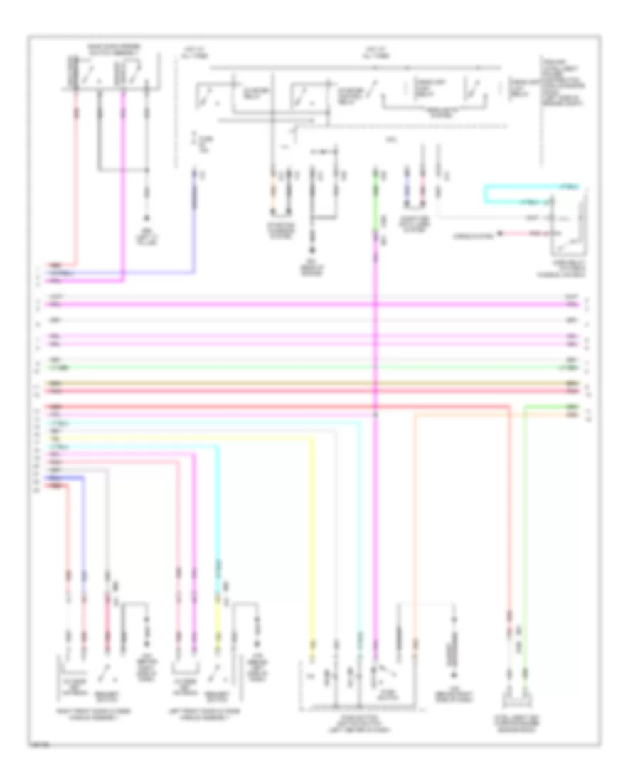
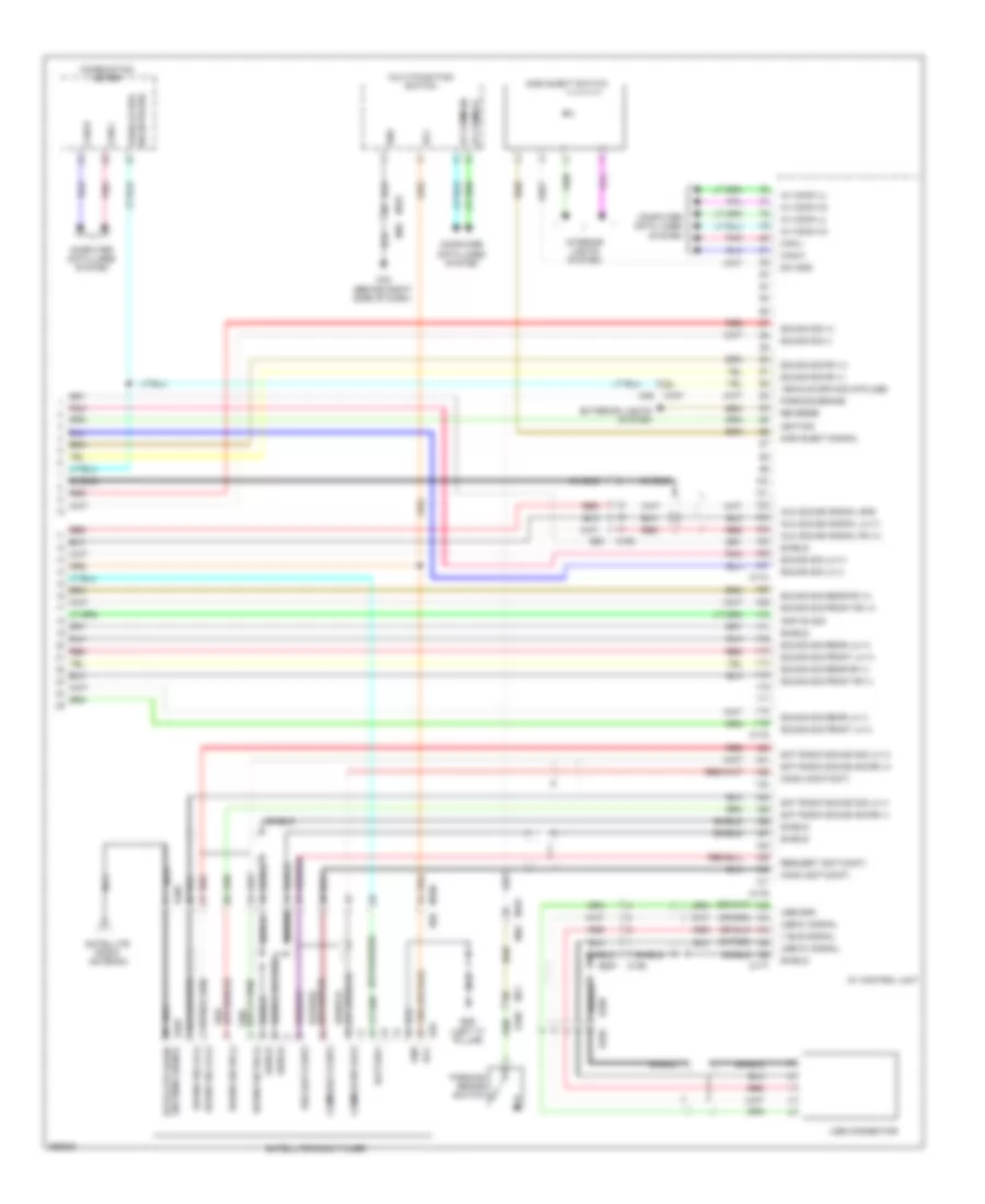
Navigation Wiring Diagram (4 of 6) for Nissan Quest LE 2013
List of elements for Navigation Wiring Diagram (4 of 6) for Nissan Quest LE 2013:
- Around view monitor control unit
- B11
- B21
- B222
- B238
- B272
- B31
- B32
- B50
- B69
- Bat pwr sply
- Cam image sig
- Camera
- Can-h
- Can-l
- Computer data lines system
- D111
- D112
- D152
- D21
- D41
- D62
- E105
- E403
- E78
- Front cam gnd
- Front cam image sig
- Front cam pwr sply
- Front camera
- Gnd
- Ign sig
- Left door mirror (at mirror)
- Left front squawker
- Left slide door speaker
- Left slide door squawker
- M11
- M157
- M160
- M18
- M20
- M22
- M43 (behind right side of dash)
- M46
- M77
- M80
- Mic pow
- Mic signal
- Microphone
- Nca
- Pnk
- R106
- Rear camera
- Red
- Reverse sig
- Right door mirror (at mirror)
- Right front squawker
- Rr cam gnd
- Rr cam image sig
- Rr cam pwr sply
- Shield
- Side cam drv gnd
- Side cam drv image sig
- Side cam drv pwr sply
- Side cam pass image sig
- Side cam pass pwr sply
- Side cam pass side gnd
Navigation Wiring Diagram (5 of 6) for Nissan Quest LE 2013
List of elements for Navigation Wiring Diagram (5 of 6) for Nissan Quest LE 2013:
- Amp on signal
- Aux image gnd
- Aux image sig
- Auxiliary input jacks
- B15 (left "a" pillar)
- B238
- B239
- B243 (right "c" pillar)
- B251
- B252
- B272 b69
- B31
- B69 b272
- Battery
- D113
- D114
- D61
- E104
- Fuse & fusible link holder 2
- Fuse 15a
- Gnd
- Hot at all times
- M161 b262
- Pnk
- Red
- Right slide door speaker
- Right slide door squawker
- Shield
- Sound sig center speaker (+)
- Sound sig center speaker (-)
- Sound sig fr door woofer rh (+)
- Sound sig fr door woofer rh (-)
- Sound sig fr speaker lh (+)
- Sound sig fr speaker lh (-)
- Sound sig fr squawker lh (+)
- Sound sig fr squawker lh (-)
- Sound sig front lh (+)
- Sound sig front lh (-) bose speaker amplifier (right rear of luggage compt)
- Sound sig front rh (+)
- Sound sig front rh (-)
- Sound sig gnd
- Sound sig lh (+)
- Sound sig lugg squawker rh (+)
- Sound sig lugg squawker rh (-)
- Sound sig rear lh (+)
- Sound sig rear lh (-)
- Sound sig rear rh (+)
- Sound sig rear rh (-)
- Sound sig rh (+)
- Sound sig slide speaker lh (+)
- Sound sig slide speaker lh (-)
- Sound sig slide speaker rh (+)
- Sound sig slide speaker rh (-)
- Sound sig woofer (+)
- Sound sig woofer (-)
- Sound signal squawker (+)
- Sound signal squawker (-)
Navigation Wiring Diagram (6 of 6) for Nissan Quest LE 2013
List of elements for Navigation Wiring Diagram (6 of 6) for Nissan Quest LE 2013:
- (or red)
- Aux sound signal gnd
- Aux sound signal lh (+)
- Aux sound signal rh (+)
- Av control unit
- B222
- B238 b31
- B258
- B259
- B30 b309
- B50
- Center squawker
- D41
- Left front door woofer
- Left luggage squawker
- M159 b257
- M160
- M18
- M181
- M182
- M20 d21
- M80
- Pnk
- Red
- Right front door woofer
- Right luggage squawker
- Shield
- Sound signal lh (+)
- Sound signal lh (-)
- Sound signal rh (+)
- Sound signal rh (-)
- Usb connector
- Usb d+ signal
- Usb d- signal
- Usb gnd
- V bus signal
- Woofer
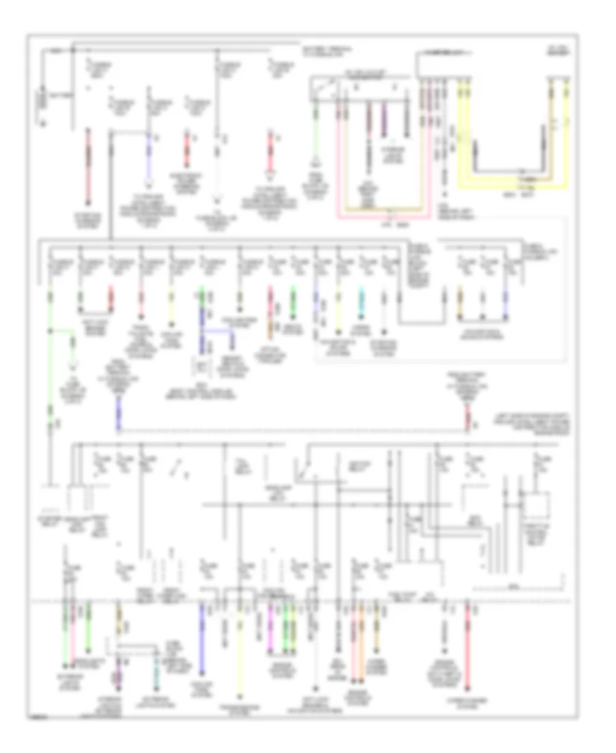
POWER DISTRIBUTION
Power Distribution Wiring Diagram (1 of 2) for Nissan Quest LE 2013
List of elements for Power Distribution Wiring Diagram (1 of 2) for Nissan Quest LE 2013:
- (left side of engine compt) ipdm e/r (intelligent power distribution module engine room)
- (not used)
- A/c relay
- Ac 120v outlet
- Ac 120v outlet main switch
- Anti-lock brakes & navigation systems
- Anti-lock brakes system
- B204
- B224 m71
- B225
- B270
- B85
- Bat (f/l)
- Battery
- Battery terminal w/ fusible link
- Bcm (body control module) (behind left side of dash)
- Cooling fan relay 1
- Cooling fans system
- Cpu
- E10
- E103
- E105 m11
- E106
- E13
- E21 (rear of engine)
- E345
- E346
- Ecm relay
- Electronic power steering system
- Engine controls system
- Engine controls, anti-theft & door locks systems
- Exterior lights system
- F12
- From battery terminal w/ fusible link (diagram 1 of 2)
- From fuse block j/b (diagram 2 of 2)
- Front fog lamp relay
- Front wiper high relay
- Front wiper relay
- Fuel pump relay
- Fuse & fusible link block (left side of engine compt)
- Fuse & fusible link holder 2
- Fuse 10a
- Fuse 15a
- Fuse 20a
- Fuse 30a
- Fuse block (j/b) (behind b6
- Fuse n/a
- Fusible link a 250a
- Fusible link b 100a
- Fusible link c 60a
- Fusible link d 100a
- Fusible link e 80a
- Fusible link f 30a
- Fusible link g 20a
- Fusible link h 40a
- Fusible link j 40a
- Fusible link k 40a
- Fusible link l 40a
- Fusible link m 40a
- Fusible link n 100a
- Headlamp high relay
- Headlamp low relay
- Headlights system
- Horns system
- Ignition relay
- Interior lights & exterior lights systems
- Interior lights system
- Inverter unit
- Left side of dash)
- M123
- M43 (behind right side dash)
- M76 (behind left side of dash)
- M79
- Memory, seats & door locks systems
- Navigation & sound systems
- Nca
- Option connector (trailer)
- Pnk
- Red
- Seats system
- Starter relay
- Starting/ charging system
- Tail lamp relay
- Throttle control motor relay
- To fuse block j/b (diagram 2 of 2)
- To ipdm e/r (intelligent power distribution module engine room) (diagram 1 of 2)
- Transmissions system
- Trunk, tailgate, fuel doors & door locks systems
- Wiper/ washer system
- Wiper/washer system
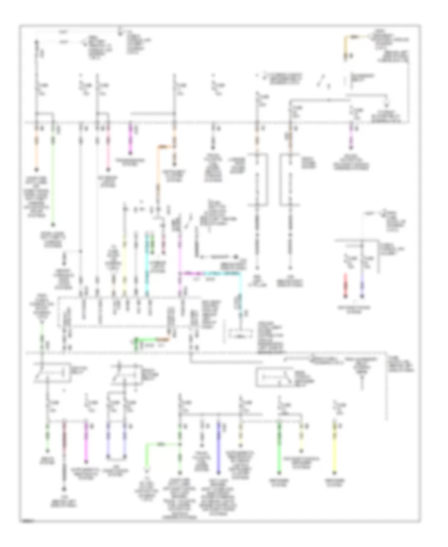
Power Distribution Wiring Diagram (2 of 2) for Nissan Quest LE 2013
List of elements for Power Distribution Wiring Diagram (2 of 2) for Nissan Quest LE 2013:
- (behind left side of dash) fuse block (j/b)
- (f/b) cont ign rly
- 10c
- 10g
- 11c
- 11f
- 12c
- 12f
- 12g
- Acc
- Acc ind
- Accessory relay
- Air conditioning & defogger systems
- Air conditioning system
- Anti-lock brakes, shift interlock, electronic power steering, exterior lights, engine controls & air conditioning systems
- B26 (left "c" pillar)
- Bat (fuse)
- Bcm (body control module) (behind left side of dash)
- Computer data lines, air conditioning, anti-lock brakes, trunk, tailgate, fuel doors, navigation, sound & mirrors systems
- Computer data lines, air conditioning, door locks, anti-theft, mirrors navigation & sound systems
- Cont acc rly
- Cont out blwr rly
- Cpu
- Def rly rr wind
- Defogger system
- Door locks, anti-theft & warning systems
- E10
- E101
- E102
- E103
- E105
- E105 m11
- Exterior lights system
- From accessory relay (diagram 2 of 2)
- From battery terminal w/ fusible link (diagram 1 of 2)
- From bcm(body control module) (diagram 2 of 2)
- From fuse & fusible link block (diagram 1 of 2)
- From fuse 8 d (diagram 2 of 2)
- From fuse block j/b (diagram 2 of 2)
- Front blower relay
- Front power socket
- Fuse & fusible link holder 1
- Fuse 10a
- Fuse 15a
- Fuse 20a
- Fuse block (j/b) (behind left side of dash)
- Ignition relay
- Illumi- nation
- Instrument cluster system
- Interior lights system
- Ipdm e/r (intelligent power distribution module engine room) (left side of engine compt)
- Lock
- Lock ind
- Luggage room power socket
- M11
- M121
- M123
- M124
- M35 (behind right side of dash)
- M43 (behind right side of dash)
- M76 (behind left side of dash)
- Memory, warning & door locks systems
- On ind
- Pnk
- Push button ignition switch (left center of dash)
- Push sw
- Push switch
- Rear window defogger relay
- Red
- Seats system
- Sound, navigation, air conditioning & mirrors systems
- Stop lp sw2
- To ac 120v outlet main switch (diagram 1 of 2)
- To front blower relay (diagram 2 of 2)
- To fuse & fusible link holder 1 (diagram 2 of 2)
- To fuse block j/b (diagram 2 of 2)
- To rear window defogger relay (diagram 2 of 2)
- Transmissions system
- Trunk, tailgate, fuel doors system
- Trunk, tailgate, fuel doors, seats & warning systems
POWER DOOR LOCKS
Power Door Locks Wiring Diagram (1 of 4) for Nissan Quest LE 2013
List of elements for Power Door Locks Wiring Diagram (1 of 4) for Nissan Quest LE 2013:
- (behind left side of dash) bcm (body control module)
- (behind left side of dash) m76
- (behind right side of dash) m35
- Acc ind
- All door lock output
- B11
- B225
- B32
- Back door opener sw
- Back door request sw
- Bat
- Between full stroke & n
- Bk door open
- Bk door sw
- Can-h
- Can-l
- Computer data lines system
- D152
- D159
- D188
- D21
- D41 m18
- Dongle link
- Dongle unit (canada)
- Door key cylinder switch
- Door lk & unlk sw lock
- Door lk & unlk sw unlock
- Door lock & unlock switch
- Door lock actuator
- Dr door ant+
- Dr door ant-
- Dr door req sw
- Dr door unlk output
- Dr door unlk sens
- Driver door lock assembly
- Driver door sw
- Driver side front door switch
- E105
- Exterior lights system
- Front passenger door lock assembly
- Full stroke
- Gnd
- Hazard sw
- I-key warn buzzer
- Int room lamp cont
- Int room lamp pwr sply
- Interface
- Interior lights system
- Key cyl unlk sw pw sw comm key cyl lock sw
- Left sliding door switch
- Lh sl door sw
- Lh sl door unlk cont
- Lh turn sig output
- Lock
- Lock ind
- Luggage room ant+
- Luggage room ant-
- M11
- M121
- M122
- M123
- M124
- M20
- M43 (behind right side of dash)
- M77
- M79
- Memory systems
- Nats ant amp
- On ind
- Pass door ant+
- Pass door ant-
- Pass door req sw
- Pass door unlk output
- Passenger door sw
- Passenger side front door switch
- Pnk
- Power window main switch
- Push sw
- Rear bumper ant+
- Rear bumper ant-
- Receiver comm
- Red
- Rh sl door sw
- Rh turn sig output
- Right sliding door switch
- Room ant1+
- Room ant1-
- Room ant2+
- Room ant2-
- Security ind cont
- Select unlk relay cont
- Sens/receiver gnd
- Stop lamp sw1
- Stop lamp sw2
- Unlock
- Unlock sensor
- W/ automatic slide door
- W/o automatic slide door
Power Door Locks Wiring Diagram (2 of 4) for Nissan Quest LE 2013
List of elements for Power Door Locks Wiring Diagram (2 of 4) for Nissan Quest LE 2013:
- (w/ automatic slide door) passenger side front power window switch
- (w/o automatic slide door) passenger side front power window switch
- B11
- B207 (right "b" pillar)
- B225
- B237
- B239
- B28
- B310
- B42
- Bat
- Batt
- Clk
- Console inside key antenna
- D111 b21
- D112
- D113
- D114
- D21
- D21 m20
- D61
- D62
- Data
- Door lock & unlock switch
- E7 f121
- Gnd
- Instrument center inside key antenna
- Left sliding door lock assembly
- Luggage room inside key antenna
- M11 e105
- M20
- M22
- M28
- M35 (behind right side of dash)
- M38
- M43 (behind right side of dash)
- M77
- M79
- Memory systems
- Nats antenna amplifier
- Pnk
- R106
- Rear bumper outside key antenna
- Red
- Remote keyless entry receiver (center of roof)
- Right sliding door lock assembly
- Shield
- Sig out
- W/ automatic slide door
- W/o automatic slide door
Power Door Locks Wiring Diagram (3 of 4) for Nissan Quest LE 2013
List of elements for Power Door Locks Wiring Diagram (3 of 4) for Nissan Quest LE 2013:
- Acc ind
- B26 (left "c" pillar)
- Back door opener switch assembly
- Computer data lines system
- Cpu
- E10
- E105
- E11
- E21 (rear of engine)
- F12
- Fuse 15a
- Headlamp high relay
- Headlamp low relay
- Headlights system
- Horn relay (in fuse & fusible link box)
- Horns system
- Hot at all times
- Intelligent key warning buzzer (engine room)
- Ipdm e/r (intelligent power distribution module engine room) (left side of engine compt)
- Left front door outside handle assembly
- Lock ind
- M11
- M18 d41
- M20 d21
- M43 (behind right side of dash)
- M76 (behind left side of dash)
- On ind
- Opener sw back door
- Outside key antenna
- Pnk
- Push button ignition switch (left center of dash)
- Push switch
- Red
- Request switch
- Right front door outside handle assembly
- Starter control relay
- Starter relay
- Starting/ charging system
Power Door Locks Wiring Diagram (4 of 4) for Nissan Quest LE 2013
List of elements for Power Door Locks Wiring Diagram (4 of 4) for Nissan Quest LE 2013:
- (behind right side of dash) m35
- (rear of engine) e21
- 11f
- 12c
- B20
- B20 d91
- B26 (left "c" pillar)
- Back door control unit (w/o automatic back door) (behind center of back door)
- Back door lock assembly
- Back door switch
- Batt +
- Buzzer
- Circuit breaker (behind left side of dash)
- Close
- Closure motor switch
- Combination meter
- Computer data lines system
- D158
- D91
- D92
- Dr lock status
- E103
- E105
- Earth
- Fuse & fusible link block (left side of engine compt)
- Fuse 10a
- Fuse 15a
- Fuse block (j/b) (behind left side of dash)
- Fusible link j 40a
- Fusible link l 40a
- Half latch switch
- Harf
- Hot at all times
- Hot w/ ignition relay energized
- Key ind
- M11
- M76 (behind left side of dash)
- M77 b11
- Open
- Open sw
- Pnk
- Red
- Security ind
- Selective unlock relay (w/ automatic slide door) (fuse block (j/b))
- Stop lamp relay
- Stop lamp switch
- Switch close
- Switch open
- Unified meter control unit
POWER MIRRORS
Auto Anti-dazzling Inside Mirror Wiring Diagram for Nissan Quest LE 2013
List of elements for Auto Anti-dazzling Inside Mirror Wiring Diagram for Nissan Quest LE 2013:
- (behind left side of dash) m76
- 2a m1
- Auto anti- dazzling inside mirror
- Fuse 3 10a
- Fuse 6 10a
- Fuse block (j/b) (behind left side of dash)
- Hot at all times
- Hot w/ ignition relay energized
- M22
- Pnk
- R106
- R107
Power Mirrors Wiring Diagram for Nissan Quest LE 2013
List of elements for Power Mirrors Wiring Diagram for Nissan Quest LE 2013:
- (behind right side of dash) m43
- Camera
- Change over switch
- D21
- D41
- Defogger system
- Door mirror remote control switch
- Down
- Driver side door mirror (at mirror)
- Exterior lights system
- Fuse 19 10a
- Fuse block (j/b) (behind left side of dash)
- Hot in on or acc
- Illumination
- Interior lights system
- Left
- Left bsw indicator
- Lights exterior
- M18
- M20
- M76 (behind left side of dash)
- Mirror
- Navigation system
- Nca
- Passenger side door mirror (at mirror)
- Pnk
- Red
- Right
- Right bsw indicator
- Switch
- System
- System defogger
- Turn signal
POWER SEATS
Front Heated Seats Wiring Diagram for Nissan Quest LE 2013
List of elements for Front Heated Seats Wiring Diagram for Nissan Quest LE 2013:
- 8c m3
- B11
- B15 (left "a" pillar)
- B207 (right "b" pillar)
- B216
- B223
- B530
- B531
- B560
- B89
- B90
- Driver side front seat
- Driver side heated seat switch
- Driver side seat cushion heater
- Driver side seat- back heater
- Fuse 15a
- Fuse block (j/b) (behind left side of dash)
- High
- Hot w/ ignition relay energized
- Interior lights system
- Low
- M43 (behind right side of dash)
- M70
- M77
- Main heater
- Off
- Passenger side front seat
- Passenger side heated seat switch
- Passenger side seat cushion heater
- Passenger side seat- back heater
- Pnk
- Sub heater
- Thermostat
- W/ memory
- W/o memory
Lumbar Wiring Diagram for Nissan Quest LE 2013
List of elements for Lumbar Wiring Diagram for Nissan Quest LE 2013:
- B15 (left "a" pillar)
- B530
- B531
- B89
- B89 b90
- B90
- Back- ward
- Bat
- Bcm (body control module) (behind left side of dash)
- Bwd
- Circuit breaker (behind left side of dash)
- Driver side front seat
- For- ward
- Fuse & fusible link block (left side of engine compt)
- Fuse 10a
- Fuse block (j/b) (behind left side of dash)
- Fusible
- Fwd
- Gnd
- Hot at all times
- Link l 40a
- Lumbar support motor
- Lumbar support switch
- M11
- M123
- M35 (behind right side of dash)
- M77
- Pnk
- Pw pwr sply (bat)
- Red
- Red (or pnk)
- W/ memory
- W/o memory
Power Seat Wiring Diagram for Nissan Quest LE 2013
List of elements for Power Seat Wiring Diagram for Nissan Quest LE 2013:
- 7a m1
- B11
- B15 (left "a" pillar)
- B207 (right "b" pillar)
- B216
- B223
- B531
- B560
- B90
- Bat
- Bcm (body control module) (behind left side of dash)
- Bwd
- Down
- Driver side front lifting motor
- Driver side front seat
- Driver side power seat switch
- Driver side rear lifting motor
- Driver side reclining motor
- Driver side sliding motor
- E105
- Front lifting switch
- Fuse & fusible link block (left side of engine compt)
- Fuse 10a
- Fuse block (j/b) (behind left side of dash)
- Fusible link l 40a
- Fwd
- Gnd1
- Hot at all times
- M11
- M123
- M35 (behind right side of dash)
- M70
- M77
- Nca
- Passenger side front seat
- Passenger side power seat switch
- Passenger side reclining motor
- Passenger side sliding motor
- Pnk
- Pw pwr
- Rear lifting switch
- Reclining switch
- Sliding switch
Third Row Folding Seat Wiring Diagram for Nissan Quest LE 2013
List of elements for Third Row Folding Seat Wiring Diagram for Nissan Quest LE 2013:
- (left "c" pillar) b26
- (or nca)
- (right "c" pillar) b208
- B11
- B19
- B228
- B26 (left "c" pillar)
- B486
- B487
- B488
- B492
- B492 b493
- B493
- B493 b492
- B56
- Bwd
- Can-h
- Can-l
- Combination meter
- Computer data lines system
- E104
- Fold
- Fuse & fusible link block (left side of engine compt)
- Fuse 10a
- Fuse 30a
- Fuse block (j/b) (behind left side of dash)
- Fwd
- Hot at all times
- Left motor sensor
- Left power return motor
- Left power return motor assembly
- Left seat device assembly
- Left seatback angle limit switch
- Left seatback lock release actuator
- Left seatback lock release actuator relay
- Left sector gear position limit switch
- Left third seat fold switch
- M77
- Nca
- Pnk
- Red
- Red b486
- Red b492
- Right motor sensor
- Right power return motor
- Right power return motor assembly
- Right seat device assembly
- Right seatback angle limit switch
- Right seatback lock release actuator
- Right seatback lock release actuator relay
- Right sector gear position limit switch
- Right third seat fold switch
- Rtn
- Seatback power return control unit
- Vss sig
POWER TOP/SUNROOF
Power Top/Sunroof Wiring Diagram for Nissan Quest LE 2013
List of elements for Power Top/Sunroof Wiring Diagram for Nissan Quest LE 2013:
- Bat
- Body control module (bcm) (behind left side of dash)
- Close sw (map)
- Closeswbit-1
- Com
- Combination meter
- D41 m18
- Door lock & unlock switch
- Down/open
- Front sunroof motor assembly
- Front sunroof switch
- Front sunroof switch up/close
- Fuse & fusible link box (left side of engine compt)
- Fuse 10a
- Fuse block (j/b) (behind left side of dash)
- Fusible link l 40a
- Gnd
- Hot at all times
- Ign (timer)
- Key cyl lock sw
- M121
- M123
- M34
- M35 (behind right side of dash)
- M73
- M76 (behind left side of dash)
- Open sw (map)
- Openswbit-0
- Pnk
- Power window main switch
- Pw pwr sply (bat)
- Pw pwr sply (ign)
- Pw sw comm
- R111
- Rear sunroof motor assembly
- Rear sunroof switch
- Red
- Up/close
- Vech spd sig
- Vech speed (8-pul)
- W/ automatic sliding door
- W/o automatic sliding door
POWER WINDOWS
Power Windows Wiring Diagram, with Driver & Passenger Side Anti-Pinch System (1 of 2) for Nissan Quest LE 2013
List of elements for Power Windows Wiring Diagram, with Driver & Passenger Side Anti-Pinch System (1 of 2) for Nissan Quest LE 2013:
- (or red)
- 7a m1
- B11
- B15 (left "a" pillar)
- B21
- B225
- B42
- Bat
- Bcm (body control module) (behind left side of dash)
- Between full stroke & n
- Can-h
- Can-l
- Computer data lines system
- D111
- D112 pnk (or red)
- D41
- D62
- Down
- Dr door sw
- Driver side front door switch
- Driver side front power window motor
- E105
- Encoder
- Full stroke
- Fuse & fusible link block (left side of engine compt)
- Fuse 10a
- Fuse block (j/b) (behind left side of dash)
- Fusible link l 40a
- Gnd
- Hot at all times
- Illu
- Illumination
- Key cyl lk sw
- Left front door lock assembly (key cylinder switch)
- Left sliding door power window motor
- Left sliding door power window switch
- Left sliding door switch
- Lock
- Lock switch
- M11
- M121
- M122
- M123
- M18
- M35 (behind right side of dash)
- M38
- M76 (behind left side of dash)
- M77
- M79
- Module
- Pass door sw
- Passenger side front door switch
- Pnk
- Power window main switch
- Pw pwr sply (bat)
- Pw pwr sply (ign)
- Pw sw comm
- Red
- Right sliding door switch
- Unlock
- Unlock switch
- W/ automatic sliding door
- W/o automatic sliding door
Power Windows Wiring Diagram, with Driver & Passenger Side Anti-Pinch System (2 of 2) for Nissan Quest LE 2013
List of elements for Power Windows Wiring Diagram, with Driver & Passenger Side Anti-Pinch System (2 of 2) for Nissan Quest LE 2013:
- B208 (right "c" pillar)
- B237
- B239 red
- B42
- Bat
- Com
- D113
- D114 pnk (or red)
- D21
- D61
- Encoder
- Front passenger power window switch
- Illumination
- M20
- M28
- M35 (behind right side of dash)
- M38
- Module
- Passenger side front power window motor
- Pnk
- Pnk m20
- Red
- Right sliding door power window motor
- Right sliding door power window switch
Power Windows Wiring Diagram, with Driver Side Anti-Pinch System for Nissan Quest LE 2013
List of elements for Power Windows Wiring Diagram, with Driver Side Anti-Pinch System for Nissan Quest LE 2013:
- (or red) pnk
- B11
- B15 (left "a" pillar)
- B208 (right "c" pillar)
- B21
- B225
- B237
- B239 d113
- B42
- Bat
- Bcm (body control module) (behind left side of dash)
- Can-h
- Can-l
- Computer data lines system
- D111
- D111 b21
- D112 d62
- D113 b239
- D114
- D21
- D21 m20
- D41 m18
- D61
- D61 d114
- D62 d112
- Down
- Dr door sw
- Driver side front door switch
- Driver side front power window motor
- Encoder
- Fuse & fusible link block (left side of engine compt)
- Fuse 10a
- Fuse block (j/b) (behind left side of dash)
- Fusible link l 40a
- Gnd
- Hot at all times
- Illumination
- Left sliding door
- Left sliding door power window motor
- Left sliding door power window switch
- Lock
- Lock switch
- M11
- M121
- M122
- M123
- M18 d41
- M20
- M28
- M35 (behind right side of dash)
- M38
- M43 (behind right side of dash)
- M76 (behind left side of dash)
- M77
- M79
- Module
- Pass door sw
- Passenger side
- Passenger side front door switch
- Passenger side front power window motor
- Passenger side front power window switch
- Pnk
- Power window main switch
- Pwr wdw bat
- Pwr wdw ign
- Red
- Right sliding door
- Right sliding door power window motor
- Right sliding door power window switch
- Unlock
RADIO
Radio Wiring Diagram, Base with Separate Display (1 of 4) for Nissan Quest LE 2013
List of elements for Radio Wiring Diagram, Base with Separate Display (1 of 4) for Nissan Quest LE 2013:
- Acc
- Aux image sig
- Aux image sig gnd
- Av control unit
- B32
- B50
- Battery
- Bcm (behind left side of dash)
- Cam gnd
- Cam image sig
- Cam pwr sply
- Can-h
- Can-l
- Comm (cont disp)
- Comm (disp cont)
- Composite image sig
- Composite image sig gnd
- Computer data lines system
- D152
- Dimmer
- Dimmer sig
- E105
- Fuse & fusible link block (left side of engine compt)
- Fuse 10a
- Fuse 15a
- Fuse 20a
- Fuse block (j/b) (behind left side of dash)
- Gnd
- Hot at all times
- Hot in acc or on
- Hot w/ ignition relay energized
- Inverter gnd
- Inverter vcc
- M11
- M121
- M157
- M160
- M171
- M172
- M173
- M43 (behind right side of dash)
- M46
- Pnk
- Rear view camera
- Red
- Rgb (r:red) sig
- Rgb area (ys) sig
- Rgb sync
- Shield
- Signal gnd
- Signal vcc
- Snd sig fr spkr lh (+)
- Snd sig fr spkr lh (-)
- Snd sig fr spkr rh (+)
- Snd sig fr spkr rh (-)
- Snd sig slide spkr lh (+)
- Snd sig slide spkr lh (-)
- Snd sig slide spkr rh (+)
- Snd sig slide spkr rh (-)
- Strg sw a
- Strg sw b
- Strg sw gnd
Radio Wiring Diagram, Base with Separate Display (2 of 4) for Nissan Quest LE 2013
List of elements for Radio Wiring Diagram, Base with Separate Display (2 of 4) for Nissan Quest LE 2013:
- (8-pulse)
- Acc
- Av comm (h)
- Av comm (l)
- B216
- B239
- B50
- Battery
- Combination switch (spiral cable)
- Comm (cont->disp)
- Comm (disp->cont)
- Composite image sig
- Composite image sig gnd
- Computer data lines system
- Control sig
- D113
- D114
- D21
- D61
- Front display unit
- Gnd
- Ign
- Illum
- Interior lights system
- Inverter gnd
- Inverter vcc
- M138
- M139
- M157
- M160
- M20
- M22
- M303
- M33
- M360
- M43 (behind right side of dash)
- M46
- M70
- Mic pow
- Mic sig
- Microphone
- Microphone gnd
- Microphone sig
- Microphone vcc
- Nca
- Pnk
- R106
- Red
- Rgb (g:green) sig
- Rgb (r:red) sig
- Rgb area (ys) sig
- Rgb sync
- Right front door woofer
- Right front squawker
- Right slide door squawker
- Seek down
- Seek up
- Shield
- Sig gnd
- Signal vcc
- Sound sig (+)
- Sound sig (-)
- Source
- Steering switch
- Tel adapter unit
- Tel antenna
- Tel antenna sig
- Telephone end
- Vehicle spd
- Voice/ telephone
- Volume down
- Volume up
Radio Wiring Diagram, Base with Separate Display (3 of 4) for Nissan Quest LE 2013
List of elements for Radio Wiring Diagram, Base with Separate Display (3 of 4) for Nissan Quest LE 2013:
- (behind left side of dash) steering angle sensor
- Acc
- Aux image gnd
- Aux image sig
- Auxiliary input jacks
- Av comm (h)
- Av comm (l)
- B11
- B15 (left "a" pillar)
- B21
- B69 b272
- Bat
- Composite img sig
- Composite img sig gnd
- Computer data lines system
- D111
- D112
- D41
- D62
- Gnd
- Hdphn snd sig lh (+)
- Hdphn snd sig lh (-)
- Hdphn snd sig rh (+)
- Hdphn snd sig rh (-)
- Ign
- Ill
- Interior lights system
- Left front door woofer
- Left front squawker
- Left slide door speaker
- M157
- M160 b50
- M170
- M18
- M46
- M76 (behind left side of dash)
- M77
- Pnk
- R34
- Rear display unit
- Red
- Shield
- Sound sig gnd
- Sound sig lh (+)
- Sound sig rh (+)
Radio Wiring Diagram, Base with Separate Display (4 of 4) for Nissan Quest LE 2013
List of elements for Radio Wiring Diagram, Base with Separate Display (4 of 4) for Nissan Quest LE 2013:
- (or red)
- (or shield)
- Acc
- Am fm main
- Am-fm main
- Antenna amp on sig
- Antenna amplifier
- Aux sound sig gnd
- Aux sound sig lh (+)
- Aux sound sig rh (+)
- Av comm (h)
- Av comm (l)
- Av control unit
- B258
- B259
- B26 (left "c" pillar)
- B482
- B485
- B49
- B50
- Batt
- Can-h
- Can-l
- Combination meter
- Comm
- Computer data lines system
- Disc eject switch
- Disk eject sig
- E105
- Exterior lights system
- Fm sub
- Fm sub glass antenna
- Gnd
- Hd phn sound sig lh (+)
- Hd phn sound sig lh (-)
- Hd phn sound sig rh (+)
- Hd phn sound sig rh (-)
- Hp shield
- Ign
- Interior lights system
- M11
- M157
- M159 b257
- M160
- M174
- M176
- M177
- M352
- M361
- M362
- M364
- M365
- M43 (behind right side of dash)
- M46
- Main glass antenna
- Multi-function switch
- Nca
- Parking brake
- Parking brake switch
- Pnk
- Red
- Request
- Reverse
- Sat radio ant sig
- Sat radio sound sig lh (+)
- Sat radio sound sig lh (-)
- Sat radio sound sig rh (+)
- Sat radio sound sig rh (-)
- Satellite radio antenna
- Satellite radio tuner
- Shield
- Sound sig (+)
- Sound sig (-)
- Sw gnd
- Sw sig park brake
- Usb connector
- Usb d+ sig
- Usb d- sig
- Usb gnd
- V bus sig
- Vehicle spd sig (8-pulse)
Radio Wiring Diagram, Base without Separate Display for Nissan Quest LE 2013
List of elements for Radio Wiring Diagram, Base without Separate Display for Nissan Quest LE 2013:
- Acc
- Antenna amplifier
- Audio unit
- B11
- B21 d111
- B216
- B239
- Batt
- D112 d62
- D113
- D114
- D21
- D41
- D61
- E105
- Fuse & fusible link block (left side of engine compt)
- Fuse 10a
- Fuse 20a
- Fuse block (j/b) (behind left side of dash)
- Glass antenna (fm sub)
- Glass antenna (main)
- Gnd
- Hot at all times
- Hot w/ accessory relay energized
- Ill (+)
- Ill (-)
- Interior lights system
- Left front door woofer
- Left slide door speaker
- Lh fr sun sig (+)
- Lh fr sun sig (-)
- Lh slide sun sig (+)
- Lh slide sun sig (-)
- M11
- M141
- M18
- M20
- M252
- M350
- M361 m362
- M364
- M365
- M43 (behind right side of dash)
- M70
- M77
- Nca
- Pnk
- Red
- Rh fr sun sig (+)
- Rh fr sun sig (-)
- Rh slide door spkr sun sig (-)
- Rh slide sun sig (+)
- Right front door woofer
- Right slide door speaker
Radio Wiring Diagram, Bose with Navigation (1 of 6) for Nissan Quest LE 2013
List of elements for Radio Wiring Diagram, Bose with Navigation (1 of 6) for Nissan Quest LE 2013:
- Antenna amplifier
- Antenna signal
- Av comm (h)
- Av comm (l)
- Av control unit
- Can-h
- Can-l
- Comm (cont-disp)
- Comm (disp-cont)
- Composite image signal
- Composite image signal gnd
- Composite image sync
- Computer data lines system
- Dimmer signal
- E105
- Exterior lights system
- Fuse & fusible link block (left side of engine compt)
- Fuse 10a
- Fuse 20a
- Fuse block (j/b) (behind left side of dash)
- Glass antenna (fm sub)
- Glass antenna (main)
- Gps antenna
- Gps antenna sig
- Hot at all times
- Hot in acc or on
- Hot in on or start
- Ignition
- Interior lights system
- M11
- M157
- M180
- M351
- M353
- M356
- M357
- M361
- M362
- M364
- M365
- M366
- M367
- M368
- M369
- M370
- M46
- Microphone signal
- Microphone vcc
- Nca
- Parking brake
- Parking brake switch
- Pnk
- Red
- Reverse
- Satellite radio antenna
- Shield
- Vehicle spd sig(8-pulse)
Radio Wiring Diagram, Bose with Navigation (2 of 6) for Nissan Quest LE 2013
List of elements for Radio Wiring Diagram, Bose with Navigation (2 of 6) for Nissan Quest LE 2013:
- (behind left side of dash) steering angle sensor
- Acc
- Av comm (h)
- Av comm (l)
- Back
- Battery
- Camera image signal
- Can-h
- Can-l
- Combination meter
- Combination switch (spiral cable)
- Comm (cont-disp)
- Comm (disp-cont)
- Composite image sig
- Composite sync
- Computer data lines system
- Disc eject switch
- Enter
- Front display unit
- Fuse 15a
- Fuse block (j/b) (behind left side of dash)
- Gnd
- Hot at all times
- Illum
- Image sig gnd
- Interior lights system
- M155
- M157
- M157 m46
- M303
- M33
- M358
- M43 (behind right side of dash)
- M46
- M76 (behind left side of dash)
- Menu down
- Menu up
- Multi-function switch
- Nca
- Pnk
- Red
- Shield
- Source
- Steering switch
- Telephone
- Vehicle spd sig (8-pulse)
- Voice
- Volume down
- Volume up
Radio Wiring Diagram, Bose with Navigation (3 of 6) for Nissan Quest LE 2013
List of elements for Radio Wiring Diagram, Bose with Navigation (3 of 6) for Nissan Quest LE 2013:
- (behind right side of dash) m43
- Acc
- Amp on signal
- Aux image signal
- Aux image signal gnd
- Av comm (h)
- Av comm (l)
- Av control unit
- Bat
- Battery
- Computer data lines system
- Disk eject signal
- Gnd
- Ignition
- Illumination
- Image sig
- Image sig gnd
- Image signal
- Interior lights system
- M157
- M170
- M178
- M179
- M46
- M76 (behind left side of dash)
- Nca
- Pnk
- R34
- Rear display unit
- Red
- Shield
- Sig lh (+)
- Sig lh (-)
- Sig rh (+)
- Sig rh (-)
- Sound sig fr lh (+)
- Sound sig fr lh (-)
- Sound sig fr rh (+)
- Sound sig fr rh (-)
- Sound sig rear lh (+)
- Sound sig rear lh (-)
- Sound sig rear rh (+)
- Sound sig rear rh (-)
- Strg sw a
- Strg sw b
- Strg sw gnd
- Sw gnd
Radio Wiring Diagram, Bose with Navigation (4 of 6) for Nissan Quest LE 2013
List of elements for Radio Wiring Diagram, Bose with Navigation (4 of 6) for Nissan Quest LE 2013:
- Around view monitor control unit
- B11
- B21
- B222
- B238
- B272
- B31
- B32
- B50
- B69
- Bat pwr sply
- Cam image sig
- Camera
- Can-h
- Can-l
- Computer data lines system
- D111
- D112
- D152
- D21
- D41
- D62
- E105
- E403
- E78
- Front cam gnd
- Front cam image sig
- Front cam pwr sply
- Front camera
- Gnd
- Ign sig
- Left door mirror (at mirror)
- Left front squawker
- Left slide door speaker
- Left slide door squawker
- M11
- M157
- M160
- M18
- M20
- M22
- M43 (behind right side of dash)
- M46
- M77
- M80
- Mic pow
- Mic signal
- Microphone
- Nca
- Pnk
- R106
- Rear camera
- Red
- Reverse sig
- Right door mirror (at mirror)
- Right front squawker
- Rr cam gnd
- Rr cam image sig
- Rr cam pwr sply
- Shield
- Side cam drv gnd
- Side cam drv image sig
- Side cam drv pwr sply
- Side cam pass image sig
- Side cam pass pwr sply
- Side cam pass side gnd
Radio Wiring Diagram, Bose with Navigation (5 of 6) for Nissan Quest LE 2013
List of elements for Radio Wiring Diagram, Bose with Navigation (5 of 6) for Nissan Quest LE 2013:
- Amp on signal
- Aux image gnd
- Aux image sig
- Auxiliary input jacks
- B15 (left "a" pillar)
- B238
- B239
- B243 (right "c" pillar)
- B251
- B252
- B272 b69
- B31
- B69 b272
- Battery
- D113
- D114
- D61
- E104
- Fuse & fusible link holder 2
- Fuse 15a
- Gnd
- Hot at all times
- M161 b262
- Pnk
- Red
- Right slide door speaker
- Right slide door squawker
- Shield
- Sound sig center speaker (+)
- Sound sig center speaker (-)
- Sound sig fr door woofer rh (+)
- Sound sig fr door woofer rh (-)
- Sound sig fr speaker lh (+)
- Sound sig fr speaker lh (-)
- Sound sig fr squawker lh (+)
- Sound sig fr squawker lh (-)
- Sound sig front lh (+)
- Sound sig front lh (-) bose speaker amplifier (right rear of luggage compt)
- Sound sig front rh (+)
- Sound sig front rh (-)
- Sound sig gnd
- Sound sig lh (+)
- Sound sig lugg squawker rh (+)
- Sound sig lugg squawker rh (-)
- Sound sig rear lh (+)
- Sound sig rear lh (-)
- Sound sig rear rh (+)
- Sound sig rear rh (-)
- Sound sig rh (+)
- Sound sig slide speaker lh (+)
- Sound sig slide speaker lh (-)
- Sound sig slide speaker rh (+)
- Sound sig slide speaker rh (-)
- Sound sig woofer (+)
- Sound sig woofer (-)
- Sound signal squawker (+)
- Sound signal squawker (-)
Radio Wiring Diagram, Bose with Navigation (6 of 6) for Nissan Quest LE 2013
List of elements for Radio Wiring Diagram, Bose with Navigation (6 of 6) for Nissan Quest LE 2013:
- (or red)
- Aux sound signal gnd
- Aux sound signal lh (+)
- Aux sound signal rh (+)
- Av control unit
- B222
- B238 b31
- B258
- B259
- B30 b309
- B50
- Center squawker
- D41
- Left front door woofer
- Left luggage squawker
- M159 b257
- M160
- M18
- M181
- M182
- M20 d21
- M80
- Pnk
- Red
- Right front door woofer
- Right luggage squawker
- Shield
- Sound signal lh (+)
- Sound signal lh (-)
- Sound signal rh (+)
- Sound signal rh (-)
- Usb connector
- Usb d+ signal
- Usb d- signal
- Usb gnd
- V bus signal
- Woofer
Radio Wiring Diagram, Bose without Navigation (1 of 5) for Nissan Quest LE 2013
List of elements for Radio Wiring Diagram, Bose without Navigation (1 of 5) for Nissan Quest LE 2013:
- Acc
- Antenna amplifier
- Aux image signal
- Aux image signal gnd
- Av control unit
- B32
- B50
- Battery
- Cam image sig
- Cam pwr sply
- Camera gnd
- Camera image signal
- Comm (cont-disp)
- Comm (disp-cont)
- Composite image sig
- Composite image sig gnd
- Composite image signal
- D152
- Dimmer signal
- E105
- Fuse & fusible link block (left side of engine compt)
- Fuse 10a
- Fuse 15a
- Fuse 20a
- Fuse block (j/b) (behind left side of dash)
- Glass antenna (fm sub)
- Glass antenna (main)
- Gnd
- Hot at all times
- Hot in acc or on
- Hot in on or start
- Interior lights system
- Inverter gnd
- Inverter vcc
- M11
- M157
- M160
- M171
- M172
- M173
- M352
- M361
- M362
- M364
- M365
- M43 (behind right side of dash)
- M46
- Nca
- Pnk
- Rearview camera
- Red
- Rgb (r:red) sig
- Rgb area (ys) sig
- Rgb sync
- Shield
- Signal gnd
- Signal vcc
- Strg sw a
- Strg sw b
- Strg sw gnd
Radio Wiring Diagram, Bose without Navigation (2 of 5) for Nissan Quest LE 2013
List of elements for Radio Wiring Diagram, Bose without Navigation (2 of 5) for Nissan Quest LE 2013:
- (8-pulse)
- Acc
- Av comm (h)
- Av comm (l)
- Battery
- Combination switch (spiral cable)
- Comm (cont disp)
- Comm (disp cont)
- Composite image sig
- Composite image sig gnd
- Computer data lines system
- Control signal
- Front display unit
- Gnd
- Ignition
- Illum
- Interior lights system
- Inverter gnd
- Inverter vcc
- M138
- M139
- M157
- M157 m46
- M22
- M303
- M33
- M360
- M43 (behind right side of dash)
- M46
- Mic pow
- Mic signal
- Microphone
- Microphone gnd
- Microphone signal
- Microphone vcc
- Nca
- Pnk
- R106
- Red
- Rgb (g:green) sig
- Rgb (red) sig
- Rgb area (ys) sig
- Rgb sync
- Seek down
- Seek up
- Shield
- Sig gnd
- Signal vcc
- Sound signal (+)
- Sound signal (-)
- Source
- Steering switch
- Tel adapter unit
- Tel antenna sig
- Telephone end
- Tell antenna
- Vehicle spd
- Voice/ telephone
- Volume down
- Volume up
Radio Wiring Diagram, Bose without Navigation (3 of 5) for Nissan Quest LE 2013
List of elements for Radio Wiring Diagram, Bose without Navigation (3 of 5) for Nissan Quest LE 2013:
- (behind left side of dash) steering angle sensor
- Acc
- Av comm (h)
- Av comm (l)
- B21
- B222
- B238
- B272
- B31
- B69
- Bat
- Computer data lines system
- D111
- D112
- D62
- Gnd
- Ignition
- Illumination
- Image sig
- Image sig gnd
- Interior lights system
- Left front squawker
- Left luggage squawker
- Left slide door speaker
- Left slide door squawker
- M157 m46
- M170
- M76 (behind left side of dash)
- M80
- Pnk
- R34
- Rear display unit
- Red
- Right front squawker
- Right luggage squawker
- Shield
- Sig lh (+)
- Sig lh (-)
- Sig rh (+)
- Sig rh (-)
Radio Wiring Diagram, Bose without Navigation (4 of 5) for Nissan Quest LE 2013
List of elements for Radio Wiring Diagram, Bose without Navigation (4 of 5) for Nissan Quest LE 2013:
- Amp on signal
- Aux image gnd
- Aux image sig
- B15 (left "a" pillar)
- B222
- B238
- B238 b31
- B239
- B243 (right "c" pillar)
- B251
- B252
- B272 b69
- B30 b309
- B31
- B69 b272
- Battery
- Bose speaker amplifier (right rear of luggage compt)
- Center squawker
- D113
- D114
- D41
- D61
- E104
- Fuse & fusible link holder 2
- Fuse 15a
- Gnd
- Hot at all times
- Left front door woofer
- M161 b262
- M18
- M20 d21
- M80
- Pnk
- Red
- Right front door woofer
- Right slide door speaker
- Right slide door squawker
- Shield
- Sound sig center speaker (+)
- Sound sig center speaker (-)
- Sound sig fr door woofer rh (+)
- Sound sig fr door woofer rh (-)
- Sound sig fr squawker lh (+)
- Sound sig fr squawker lh (-)
- Sound sig fr woofer lh (+)
- Sound sig fr woofer lh (-)
- Sound sig front lh (+)
- Sound sig front lh (-)
- Sound sig front rh (+)
- Sound sig front rh (-)
- Sound sig gnd
- Sound sig lh (+)
- Sound sig lugg squawker rh (+)
- Sound sig lugg squawker rh (-)
- Sound sig rear lh (+)
- Sound sig rear lh (-)
- Sound sig rear rh (+)
- Sound sig rear rh (-)
- Sound sig rh (+) auxiliary input jacks
- Sound sig slide speaker lh (+)
- Sound sig slide speaker lh (-)
- Sound sig slide speaker rh (+)
- Sound sig slide speaker rh (-)
- Sound sig woofer (+)
- Sound sig woofer (-)
- Sound signal squawker (+)
- Sound signal squawker (-)
- Woofer
Radio Wiring Diagram, Bose without Navigation (5 of 5) for Nissan Quest LE 2013
List of elements for Radio Wiring Diagram, Bose without Navigation (5 of 5) for Nissan Quest LE 2013:
- (or red)
- (or shield) red
- Acc
- Amp on sig
- Aux sound signal gnd
- Aux sound signal lh (+)
- Aux sound signal rh (+)
- Av comm (h)
- Av comm (l)
- Av control unit
- B258
- B259
- B26 (left "c" pillar)
- B482 antenna signal
- B485
- B49
- B50
- Battery
- Can-h
- Can-l
- Combination meter
- Comm (cont-sat)
- Comm (sat-cont)
- Computer data lines system
- Disc eject switch
- Disk eject signal
- E105
- Exterior lights system
- Gnd
- Ignition
- Interior lights system
- M11
- M157
- M157 m46
- M159 b257
- M160
- M174
- M175
- M176
- M177
- M43 (behind right side of dash)
- M46
- Multi-function switch
- Nca
- Parking brake
- Parking brake switch
- Pnk
- Red
- Req (sat-cont)
- Request (sat-cont)
- Reverse
- Sat radio sound sig lh (+)
- Sat radio sound sig lh (-)
- Sat radio sound sig rh (+)
- Sat radio sound sig rh (-)
- Satellite radio
- Satellite radio antenna
- Satellite radio tuner
- Shield
- Sound sig (+)
- Sound sig (-)
- Sound sig front lh (+)
- Sound sig front lh (-)
- Sound sig front rh (+)
- Sound sig front rh (-)
- Sound sig lh (+)
- Sound sig lh (-)
- Sound sig rear lh (+)
- Sound sig rear lh (-)
- Sound sig rear rh (+)
- Sound sig rear rh (-)
- Sound sig rh (+)
- Sound sig rh (-)
- Sw gnd
- Usb connector
- Usb d+ signal
- Usb d- signal
- Usb gnd
- V bus signal
- Vehicle spd sig (8-pulse)
Radio Wiring Diagram, with Display Audio (1 of 2) for Nissan Quest LE 2013
List of elements for Radio Wiring Diagram, with Display Audio (1 of 2) for Nissan Quest LE 2013:
- (58 to 64 pins not used)
- (or red)
- Acc
- Antenna amplifier
- Antenna fm sub glass
- Audio unit
- Av comm (h)
- Av comm (l)
- B11
- B216
- B239
- B256
- B258
- B259
- B32
- Battery
- Bcm (behind left side of dash)
- Cam image sig
- Camera
- Camera gnd
- Camera pwr sply
- Can-h
- Can-l
- Combination meter
- Computer data lines system
- Control sig
- D113
- D114
- D152
- D21
- D61
- E105
- Exterior lights system
- Fuse & fusible link block (left side of engine compt)
- Fuse 10a
- Fuse 15a
- Fuse 20a
- Fuse block (j/b) (behind left side of dash)
- Gnd
- Hot at all times
- Hot w/ accessory relay energized
- Hot w/ ignition relay energized
- Illu cntrl sig (+)
- Illu cntrl sig (-)
- Image sig
- Interior lights system
- M11
- M121
- M20
- M340
- M361
- M362
- M364
- M365
- M366
- M367
- M368
- M369
- M370
- M371
- M43 (behind right side of dash)
- M70
- M77
- M92
- M93
- M94
- M96
- Main glass antenna
- Nca
- Pnk
- Rear view camera
- Red
- Reverse sig
- Right front door woofer
- Right front squawker
- Right slide door speaker
- Sat radio ant sig
- Satellite radio antenna
- Shield
- Snd sig fr spkr lh (+)
- Snd sig fr spkr lh (-)
- Snd sig fr spkr rh (+)
- Snd sig fr spkr rh (-)
- Snd sig slide spkr lh (+)
- Snd sig slide spkr lh (-)
- Snd sig slide spkr rh (+)
- Snd sig slide spkr rh (-)
- Sound sig (+)
- Sound sig (-)
- Strg sw a
- Strg sw b
- Strg sw gnd
- Usb connector
- Usb d+sig
- Usb d-sig
- Usb gnd
- V bus sig
- Vehicle spd sig (8-pulse)
- Vehicle speed (8-pluse)
Radio Wiring Diagram, with Display Audio (2 of 2) for Nissan Quest LE 2013
List of elements for Radio Wiring Diagram, with Display Audio (2 of 2) for Nissan Quest LE 2013:
- (8-pulse)
- Acc
- Av comm (h)
- Av comm (l)
- B11
- B21
- Battery
- Combination switch (spiral cable)
- Computer data lines system
- Control sig
- D111
- D112
- D41
- D62
- Gnd
- Ign
- Illum
- Interior lights system
- Left front door woofer
- Left front squawker
- Left slide door speaker
- M138
- M139
- M18
- M22
- M303
- M33
- M360
- M43 (behind right side of dash)
- M77
- Mic pow
- Mic sig
- Microphone
- Microphone gnd
- Microphone sig
- Microphone vcc
- Nca
- R106
- Red
- Seek down
- Seek up
- Shield
- Source
- Steering switch
- Strg sw a
- Strg sw b
- Strg sw gnd
- Tel adapter unit
- Tel antenna
- Tel antenna sig
- Tel voice sig (+)
- Tel voice sig (-)
- Telephone end
- Vehicle spd
- Voice/ telephone
- Volume down
- Volume up
SHIFT INTERLOCK
Shift Interlock Wiring Diagram for Nissan Quest LE 2013
List of elements for Shift Interlock Wiring Diagram for Nissan Quest LE 2013:
- (behind right side of dash) m43
- Cvt shift selector
- E103 4f
- E105
- Fuse 3 10a
- Fuse block (j/b) (behind left side of dash)
- Hot in on or start
- M11
- Park position switch
- Shift lock solenoid
- Stop lamp switch
STARTING/CHARGING
Charging Wiring Diagram for Nissan Quest LE 2013
List of elements for Charging Wiring Diagram for Nissan Quest LE 2013:
- (or red)
- 12c
- Alternator
- Batt
- Battery
- Battery terminal w/ fusible link
- Can comm line
- Charge indicator
- Combination meter
- Computer data lines system
- Cpu
- Cur sen
- E11
- E16
- E307 (front right of engine compt)
- E308
- E6 f123
- Ecm (front left side of engine)
- F12
- F123 e6
- F59
- Fuse & fusible link block (left side of engine compt)
- Fuse 10a
- Fuse block (j/b) (behind left side of dash)
- Fusible link a 250a
- Fusible link b 100a
- Hot w/ ignition relay energized
- Ipdm e/r (intelligent power distribution module engine room) (left side of engine compt)
- M11 e105
- Nca
- Pnk
- Sen pwr sply
- Sensor gnd
- Starting circuit
Starting Wiring Diagram for Nissan Quest LE 2013
List of elements for Starting Wiring Diagram for Nissan Quest LE 2013:
- Acc
- Acc ind
- Alternator
- Battery
- Battery terminal w/ fusible link
- Bcm (body control module) (behind left side of dash)
- Can-h
- Can-l
- Computer data lines system
- Cpu
- Cvt unit
- E10
- E105
- E11
- E21 (rear of engine)
- F10
- F12
- F47
- F59
- Fuse & fusible link block (left side of engine compt)
- Fuse 10a
- Fuse 15a
- Fuse block (j/b) (behind left side of dash)
- Fusible link a 250a
- Fusible link b 100a
- Fusible link h 40a
- Hot at all times
- Hot in on or start
- Illumi- nation
- Interior lights system
- Ipdm e/r (intelligent power distribution module engine room) (left side of engine compt)
- Lock
- Lock ind
- M11
- M124
- M43 (behind right side of dash)
- Nca
- On ind
- P/n pos
- Pnk
- Push button ignition switch
- Push sw
- Push switch
- Range sw 1
- Range sw 2
- Range sw 3
- Range sw 3 mon
- Range sw 4
- Starter control relay
- Starter motor
- Starter relay
- Str rly
- Str rly cont
- Tcm (transmission control module) (left front of engine compt)
- Transmission range switch
SUPPLEMENTAL RESTRAINTS
Supplemental Restraints Wiring Diagram (1 of 2) for Nissan Quest LE 2013
List of elements for Supplemental Restraints Wiring Diagram (1 of 2) for Nissan Quest LE 2013:
- (or red)
- (right "b" pillar) b207
- (under front of passenger's seat) occupant detection system control unit
- (under lower center of dash) air bag diagnosis sensor unit
- 11c
- Air bag ind
- Air bag w/l
- As1 (+)
- As1 (-)
- As2 (+)
- As2 (-)
- B15 (left "a" pillar)
- B17
- B207 (right "b" pillar)
- B223
- B246
- B530
- B560
- B79
- B89
- B90 b531
- Buckle sw sig
- Can-h
- Can-l
- Combination meter
- Communication
- Computer data lines system
- Cut off telltale
- D21 m20
- D41 m18
- Dr1 (+)
- Dr1 (-) dr2 (-)
- Dr2 (+)
- Driver side front seat
- Driver side seat belt buckle switch
- Eczs (+)
- Eczs (-)
- Fr clh (+)
- Fr clh (-)
- Fr crh (+)
- Fr crh (-)
- Fuse 2 10a
- Fuse 4 10a
- Fuse block j/b (behind left side of dash)
- Gnd
- Hot in on or start
- Ign
- Info op
- K-line
- Left front curtain air bag module
- Left front satellite sensor
- Left rear curtain air bag module
- Left rear satellite sensor (left "c" pillar)
- Left side air bag module
- Lh buckle sw in
- M3 12c
- M38 b42
- M43 (behind right side of dash)
- M59
- M70 b216
- M76 (behind left side of dash)
- Nca
- Ods ip
- Pass seat belt war sig
- Passenger side front seat
- Passenger side seat belt buckle switch
- Plh (+)
- Plh (-)
- Pnk
- Prh (+)
- Prh (-)
- R103
- Red
- Rh buckle sw in
- Rr clh (+)
- Rr clh (-)
- Rr crh (+)
- Rr crh (-)
- Satellite lh (+)
- Satellite lh (-)
- Satellite rh(+)
- Satellite rh(-)
- Seat belt w/l
- Sens lh (+)
- Sens lh (-)
- Sens rh(+)
- Sens rh(-)
- Shield
- Side sens lh2+
- Side sens lh2-
- Side sens rh2+
- Side sens rh2-
- Slh (+)
- Slh (-)
- Srh (+)
- Srh (-)
- W/ memory
- W/o memory
Supplemental Restraints Wiring Diagram (2 of 2) for Nissan Quest LE 2013
List of elements for Supplemental Restraints Wiring Diagram (2 of 2) for Nissan Quest LE 2013:
- Airbag
- B14
- B17
- B215
- Bcm (behind left side of dash)
- Combination switch (spiral cable)
- Crash zone sensor (center front of engine compt)
- Driver air bag module
- E105
- E311
- E77
- Front passenger air bag off indicator
- Left front door satellite sensor
- Left seat belt pre-tensioner (at left "b" pillar)
- M11
- M123
- M300
- M301
- M43 (behind right side of dash)
- Nca
- Passenger air bag module
- Pnk
- R103
- Red
- Right front curtain air bag module
- Right front door satellite sensor
- Right front satellite sensor
- Right rear curtain air bag module
- Right rear satellite sensor
- Right seat belt pre-tensioner (at right "b" pillar)
- Right side air bag module
- Shield
TRANSMISSION
Transmission Wiring Diagram (1 of 2) for Nissan Quest LE 2013
List of elements for Transmission Wiring Diagram (1 of 2) for Nissan Quest LE 2013:
- 12f
- Backup lamp relay
- Can-h
- Can-l
- Combination meter
- Computer data lines system
- Ctrl sw sig
- Cvt fluid temp sens
- Cvt shift selector
- Detention switch
- Door locks & anti-theft systems
- E103
- E105
- E21 (rear of engine)
- Exterior lights system
- F123
- Fuse 10a
- Fuse block (j/b) (behind left side of dash)
- Gnd
- Hot at all times
- Hot in on or start
- Illumination
- Interior lights system
- L/u select sol
- Line press sol
- M11
- M43 (behind right side of dash)
- M57
- M85
- O/d off ind
- Overdrive control switch
- Park position switch
- Pnk
- Pri press sens
- Pri speed sens
- Pwr sply
- Pwr sply (back up)
- Red
- Rom assy (sel1)
- Rom assy (sel2)
- Rom assy (sel3)
- Sec press sens
- Sec press sol
- Sec speed sens
- Secondary speed sensor
- Sens gnd
- Sens power
- Shift lock solenoid
- Starter relay
- Starting/charging system
- Step motor a
- Step motor b
- Step motor c
- Step motor d
- Stop lamp switch
- Tcm (transmission control module) (left front of engine compt)
- Torque conv clutch sol
- Transmission range sw 1
- Transmission range sw 2
- Transmission range sw 3
- Transmission range sw 3 monitor
- Transmission range sw 4
Transmission Wiring Diagram (2 of 2) for Nissan Quest LE 2013
List of elements for Transmission Wiring Diagram (2 of 2) for Nissan Quest LE 2013:
- Cvt fluid temperature sensor
- Cvt unit
- F12
- Fuse 10a
- Hot in on or start
- Ipdm e/r (intelligent power distribution module engine room) (left side of engine compt)
- Line pressure solenoid valve
- Lock-up select solenoid valve
- Primary pressure sensor
- Primary speed sensor
- Red
- Rom assembly
- Secondary pressure sensor
- Secondary pressure solenoid valve
- Step motor
- Torque converter clutch solenoid valve
- Transmission range switch
TRUNK, TAILGATE, FUEL DOOR
Back Door Wiring Diagram, with Automatic Back Door System for Nissan Quest LE 2013
List of elements for Back Door Wiring Diagram, with Automatic Back Door System for Nissan Quest LE 2013:
- +ign
- Automatic back door close switch
- Automatic back door control module (left rear of luggage compt)
- Automatic back door switch (behind left side of dash)
- Automatic back door warning buzzer
- Automatic door main switch
- B11
- B20
- B26 (left "c" pillar)
- B28
- B310
- B32
- Back door lock assembly
- Back door opener switch assembly (back door opener switch)
- Back door opnr sw
- Back door sw
- Back door switch
- Bcm (body control module) (behind left side of dash)
- Buzzer
- Can-h
- Can-l
- Circuit breaker (behind left side of dash)
- Close
- Close sw
- Close switch
- Closure motor
- Computer data lines system
- D152
- D158
- D159
- D188
- D91
- D92
- Door locks system
- Driver sw
- E105
- Exterior lights system
- Fuse & fusible link block (left side of engine compt)
- Fuse 3 10a
- Fuse 9 10a
- Fuse block (j/b) (behind left side of dash)
- Fusible link j 40a
- Gnd
- Half latch sw
- Half latch switch
- Hazard sw
- Hot at all times
- Hot in on or start
- Inside close sw
- Interior lights system
- Latch mtr close
- Latch mtr open
- Left back door touch sensor
- Lh turn sig out
- M11
- M121
- M122
- M123
- M76 (behind left side of dash)
- M77
- M77 b11
- Main sw
- Nam func flg
- Open
- Open sw
- Open switch
- Pnk
- Receiver comm
- Receiver/sens gnd
- Red
- Rh turn sig out
- Right back door touch sensor
- Touch sens gnd
- Touch sens lh
- Touch sens rh
Back Door Wiring Diagram, without Automatic Back Door System for Nissan Quest LE 2013
List of elements for Back Door Wiring Diagram, without Automatic Back Door System for Nissan Quest LE 2013:
- (behind right side of dash) m35
- B20
- B26 (left "c" pillar)
- B32
- Back door control unit (behind center of back door)
- Back door lock assembly
- Back door opener switch
- Back door opener switch assembly
- Back door switch
- Bat
- Bcm (body control module) (behind left side of dash)
- Bk door open
- Bk door opnr sw
- Bk door req sw
- Bk door sw
- Can-h
- Can-l
- Circuit breaker (behind left side of dash)
- Close
- Close switch
- Closure motor
- Combination meter
- Computer data lines system
- D152
- D158
- D159
- D188
- D91
- D92
- Dr lock status
- E105
- Earth
- Fuse & fusible link block (left side of engine compt)
- Fuse 10 10a
- Fuse block (j/b) (behind left side of dash)
- Fusible link j 40a
- Fusible link l 40a
- Gnd
- Half latch switch
- Harf
- Hot at all times
- M11
- M121
- M122
- M123
- M77 b11
- Open
- Open sw
- Open switch
- Pnk
- Red
- Request switch
Right & Left Sliding Door Wiring Diagram (1 of 2) for Nissan Quest LE 2013
List of elements for Right & Left Sliding Door Wiring Diagram (1 of 2) for Nissan Quest LE 2013:
- (left "c" pillar) b26
- 10a
- A-sig
- Automatic main door switch
- Automatic sliding door motor
- B-plr sw
- B-sig
- B11
- B15 (left "a" pillar)
- B21
- B26 (left "c" pillar)
- B33
- B45
- B46
- B47
- B53
- B65
- Bat
- Bcm (body control module) (behind left side of dash)
- Buzzer
- Can-h
- Can-l
- Child lock
- Child lock status switch
- Circuit breaker (behind left side of dash)
- Close
- Closure motor
- Closure(ret)
- Closure+(close)
- Clutch
- Clutch(+)
- Clutch(-)
- Computer data lines system
- D111
- D194
- D195
- D195 d22
- D22
- D22 d195
- D62 d112
- Door locks system
- Driver sw
- E105 m11
- Elec b
- Encoder
- Encoder gnd
- Encoder power
- Exterior lights system
- Fuel filler lid status switch
- Fuel lid sw
- Full latch switch
- Full sw
- Fuse
- Fuse & fusible link block (left side of engine compt)
- Fuse block j/b (behind left side of dash)
- Fusible link j 40a
- Gd logic
- Gnd power
- Half latch
- Handle
- Hazard sw
- Hot at all times
- Hot in on or start
- Ign
- Interior lights system
- Knob lock
- Left automatic sliding door unit
- Left door automatic sliding warning buzzer
- Left door lock sliding status switch
- Left remote control assembly
- Left sliding door control unit (behind left rear quarterpanel)
- Left sliding door lock assembly
- Left sliding door lock release actuator
- Left sliding door one-touch open/close switch
- Left sliding door switch
- Left sliding door touch sensor
- M121
- M123
- M76 (behind left side of dash)
- M77
- M77 b11
- Main sw
- Neutral sw
- Neutral switch
- One touch
- Open
- Open sw
- Pnk
- Receiver comm
- Receiver/sens gnd
- Red
- Red (or pnk)
- Release act(+)
- Release act(-)
- Return
- Rr door sw
- Sliding door handle switch
- Sliding door open/close switch (left rear)
- Sw gnd
- Switch
- Touch sens
- Turn sig lh output
- Turn sig rh output
Right & Left Sliding Door Wiring Diagram (2 of 2) for Nissan Quest LE 2013
List of elements for Right & Left Sliding Door Wiring Diagram (2 of 2) for Nissan Quest LE 2013:
- (or pnk)
- A-sig
- Automatic sliding door motor
- B-plr sw
- B-sig
- B207 (right "b" pillar)
- B208 (right "c" pillar)
- B216
- B225
- B232 d189
- B243 (right "c" pillar)
- B244
- B245
- B247
- B248
- B249
- Bat
- Buzzer
- Can-h
- Can-l
- Child lock
- Child lock status switch
- Close
- Closure motor
- Closure(ret)
- Closure+(close)
- Clutch
- Clutch(+)
- Clutch(-)
- Computer data lines system
- D113 b239
- D114 d61
- D189 b232
- D196
- D23
- D61 d114
- Driver sw
- Elec b
- Encoder
- Encoder gnd
- Encoder power
- Full latch switch
- Full sw
- Gd logic
- Gnd power
- Half latch
- Half latch switch
- Handle
- Ign
- Interior lights system
- Knob lock
- M70
- M76 (behind left side of dash)
- M79
- Main sw
- Neutral sw
- Neutral switch
- One touch
- Open
- Open sw
- Pnk
- Red
- Red (or pnk)
- Release actor(+)
- Release actor(-)
- Return
- Right automatic sliding door unit
- Right door automatic sliding buzzer warning
- Right remote control assembly
- Right sliding door control unit (behind right rear quarterpanel)
- Right sliding door lock assembly
- Right sliding door lock release actuator
- Right sliding door lock status switch
- Right sliding door one-touch open/close switch
- Right sliding door switch
- Right sliding door touch sensor
- Rr door sw
- Sliding door handle switch
- Sliding door open/close switch (front side)
- Sliding door open/close switch (right rear)
- Sw sig
- Touch sens
WARNING SYSTEMS
Chime Wiring Diagram for Nissan Quest LE 2013
List of elements for Chime Wiring Diagram for Nissan Quest LE 2013:
- (behind right side of dash) m35
- 11f
- 12c
- Air bag diagnosis sensor unit (under lower center of dash)
- Air bag sig
- Air bag w/l
- B11
- B15 (left "a" pillar)
- B42
- B530
- B79
- B89
- B90 b531
- Bat
- Bat (fuse)
- Batt
- Bcm (body control module) (behind left side of dash)
- Buzzer
- Can-h
- Can-l
- Combi sw input 1
- Combi sw input 2
- Combi sw input 3
- Combi sw input 4
- Combi sw input 5
- Combi sw output 1
- Combi sw output 2
- Combi sw output 3
- Combi sw output 4
- Combi sw output 5
- Combination meter
- Combination switch
- Computer data lines system
- Driver door sw
- Driver side front door switch
- Driver side front seat
- Driver side seat belt buckle switch
- E103
- E105
- Fuse & fusible link block (left side of engine compt)
- Fuse 10a
- Fuse 15a
- Fuse block (j/b) (behind left side of dash)
- Fusible link l 40a
- Gnd
- Hot at all times
- Hot w/ ignition relay energized
- I-key warn buzzer
- Ign sig
- Input 1
- Input 2
- Input 3
- Input 4
- Input 5
- Intelligent key warning buzzer
- Lh buckle sw
- M11
- M121
- M122
- M123
- M124
- M38
- M59
- M76 (behind left side of dash)
- M77
- Output 1
- Output 2
- Output 3
- Output 4
- Output 5
- Park brk sw sig
- Parking brake switch
- Pnk
- Red
- Seat belt buckle sw
- Seat belt w/l
- W/ memory
- W/o memory
- Warning sig
Tire Pressure Monitoring Wiring Diagram for Nissan Quest LE 2013
List of elements for Tire Pressure Monitoring Wiring Diagram for Nissan Quest LE 2013:
- Bat
- Bat (f/l)
- Batt
- Bcm (body control module) (behind left side of dash)
- Can-h
- Can-l
- Combination meter
- Computer data lines system
- Fuse & fusible link block (left side of engine compt)
- Fuse 10a
- Fuse block (j/b) (behind left side of dash)
- Fusible link l 40a
- Gnd
- Hot at all times
- M1 7a
- M121
- M123
- M22
- M35 (behind right side of dash)
- Pnk
- R106
- Receiver comm
- Receiver/sens gnd
- Red
- Remote keyless entry receiver (tire pressure receiver) (center of roof)
- Sig
- Tire pressure ind & buzzer
- Tire pressure sensors
WIPER/WASHER
Wiper/Washer Wiring Diagram for Nissan Quest LE 2013
List of elements for Wiper/Washer Wiring Diagram for Nissan Quest LE 2013:
- B11
- B20
- B26 (left "c" pillar)
- B32
- Bat
- Bcm (body control module) (behind left side of dash)
- Can-h
- Can-l
- Combination meter
- Combination switch
- Computer data lines system
- Cpu
- D152
- D158
- D159
- D188
- D91
- D92
- E10
- E105 m11
- E11
- E21 (rear of engine)
- E309 (front left of engine compt)
- E339
- E339 e8
- E345
- Front wiper high relay
- Front wiper motor
- Front wiper relay
- Fuse & fusible link block (left side of engine compt)
- Fuse 10a
- Fuse 15a
- Fuse 30a
- Fuse block (j/b) (behind left side of dash)
- Fusible link l 40a
- Gnd
- High
- Hot at all times
- Ign
- Ignition relay
- Input 1
- Input 2
- Input 3
- Input 4
- Input 5
- Ipdm e/r (intelligent power distribution module engine room) (left side of engine compt)
- Low
- M11 e105
- M121
- M122
- M123
- M35 (behind right side of dash)
- M76 (behind left side of dash)
- M77
- Move
- Output 1
- Output 2
- Output 3
- Output 4
- Output 5
- Pnk
- Rear wip output
- Rear wiper motor
- Red
- Stop
- Stop pos
- Washer level switch
- Washer lvl sw
- Washer pump

 Čeština
 Dansk
Dansk Deutsch
 Ελληνικά
 English
 English
 Español
 Suomi
Suomi Français
 עברית
עברית Hrvatski
 Magyar
 Italiano
 日本語
日本語 한국어
한국어 Nederlands
 Polski
 Português
 Português
 Română
 Русский
 Slovenčina
 Slovenščina
 Svenska
 Türkçe
 中文 (中国)