AIR CONDITIONING
Compressor Wiring Diagram for Pontiac G5 2009
 https://portal-diagnostov.com/license.html
Automotive Electricians Portal FZCO
Automotive Electricians Portal FZCO
https://portal-diagnostov.com/license.html
https://portal-diagnostov.com/license.html
Automotive Electricians Portal FZCO
Automotive Electricians Portal FZCO
List of elements for Compressor Wiring Diagram for Pontiac G5 2009:
- 5v ref
- A/c cltch relay
- A/c clutch fuse 10a
- A/c compressor clutch (left front of engine)
- A/c compressor clutch diode
- A/c refrigerant pressure sensor (right front of engine compt, on a/c line, near compressor)
- A/c req sig
- A/c request indicator
- A/c request sig
- A/c request switch
- Batt
- Body control module (bcm) (under center dash)
- Computer data lines system
- Ect sig
- Engine control module (ecm) (left side of engine compt)
- Engine coolant temperature (ect) sensor (rear of engine)
- G101 (left side of engine compt, under coolant reservoir)
- G203 (behind right side of dash)
- Gnd
- Hot at all times
- Hot w/ pwr/ trn relay energized
- Hot w/ run/ crnk relay energized
- Hvac control module (center of dash, below radio)
- Hvac/ ip ign fuse 16 10a
- Hvac/pk3 + fuse 10 10a
- Ign voltage
- Logic
- Low ref
- Pnk
- Power distribution system
- Press sens sig
- Rly ctrl
- Serial data
- Tan
- Underhood fuse block (engine compt, next to left strut tower)
- X3 f2
- X5 a4
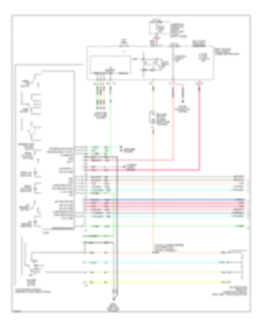
Manual A/C Wiring Diagram (1 of 2) for Pontiac G5 2009
List of elements for Manual A/C Wiring Diagram (1 of 2) for Pontiac G5 2009:
- (in hvac jumper harness, 4.9 cm from hvac control assembly) j261
- (not used)
- 5 volt ref
- A/c req sig
- A/c request indicator
- A/c request sig
- A/c request switch
- Air temp dr cntrl
- Air temp dr pos
- Batt
- Bcm 3 fuse 30a
- Blower motor (under right side of dash)
- Blower motor resistor (under right side of dash, next to blower motor)
- Blower motor switch
- Body control module (bcm) (under center dash)
- Close recir door
- Computer data lines system
- Defogger system
- Fresh air indicator
- Fresh air switch
- G203 (behind right side of dash)
- Gnd
- Ground
- High
- Hot at all times
- Hot w/ run/ crnk relay energized
- Hvac control module (center of dash, below radio)
- Hvac relay
- Hvac/ ip ign fuse 16 10a
- Hvac/pk3 + fuse 10 10a
- Ign voltage
- Interior lights system
- Logic
- Low
- Mode door cntrl
- Mode door pos sig
- Mode switch
- Off
- Open recir door
- Pnk
- Power distribution system
- Recir- culation indicator
- Recir- culation switch
- Rr defog relay cntrl
- Rr defog switch sig
- Serial data
- Tan
- Temperature control switch
- Underhood fuse block (engine compt, next to left strut tower)
- X4 c2
- X4 f4
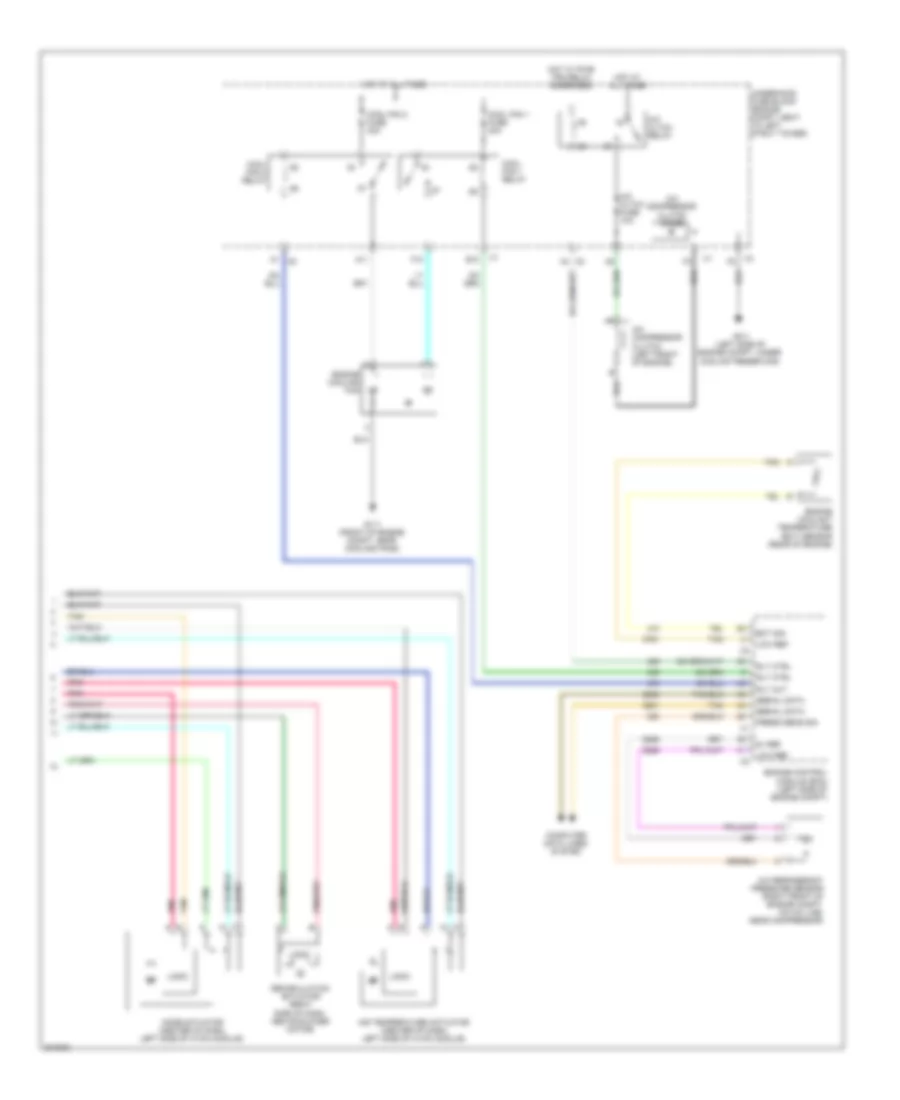
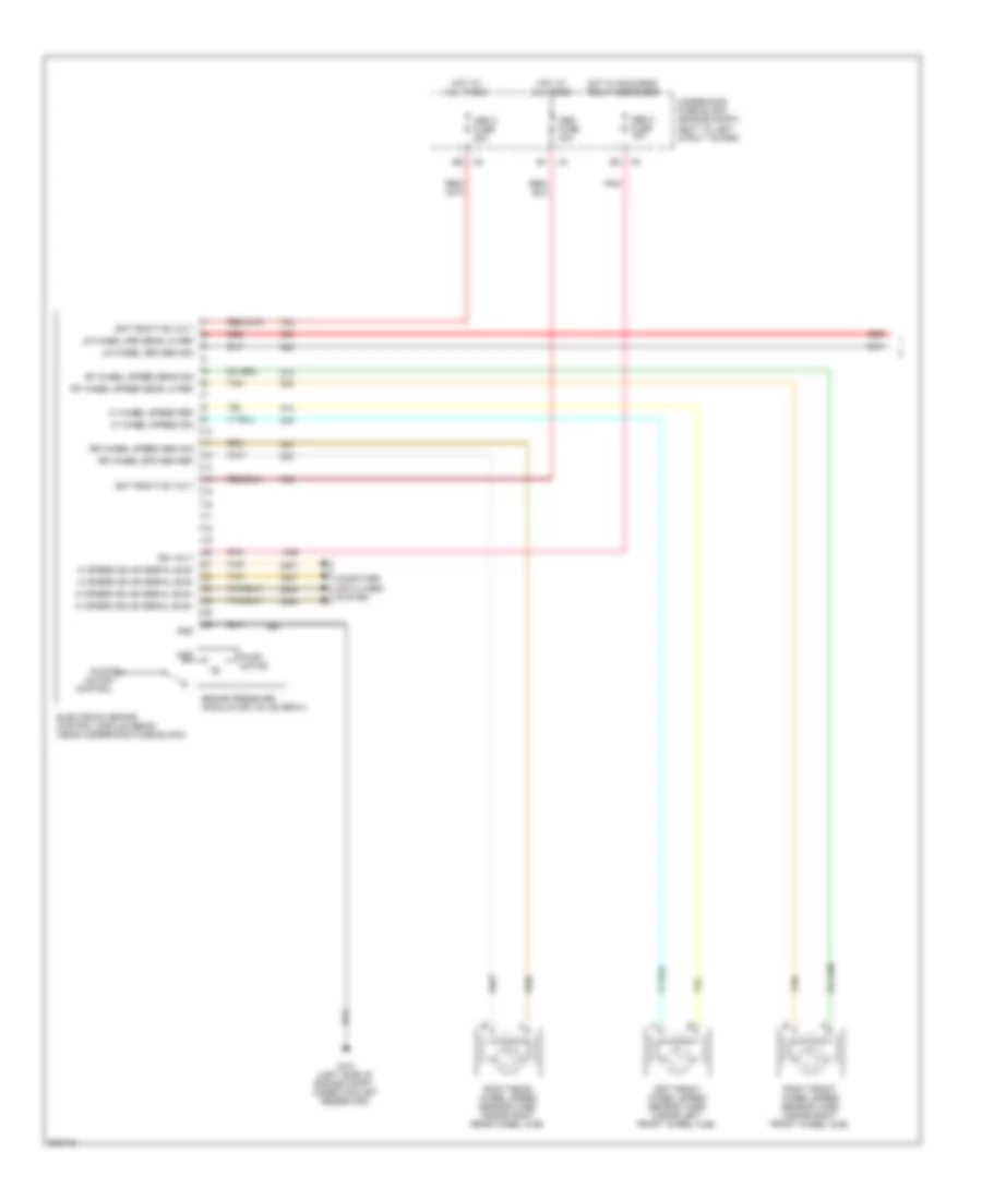
Manual A/C Wiring Diagram (2 of 2) for Pontiac G5 2009
List of elements for Manual A/C Wiring Diagram (2 of 2) for Pontiac G5 2009:
- 5v ref
- A/c cltch fuse 10a
- A/c cltch relay
- A/c compressor clutch (left front of engine)
- A/c compressor clutch diode
- A/c refrigerant pressure sensor (right front of engine compt, on a/c line, near compressor)
- A1 x5
- A11
- Air temperature actuator (center of dash, left side of hvac module)
- Computer data lines system
- Cool fan 1 fuse 30a
- Cool fan 1 relay
- Cool fan 2 fuse 30a
- Cool fan 2 relay
- E10
- Ect sig
- Engine control module (ecm) (left side of engine compt)
- Engine coolant temperature (ect) sensor (rear of engine)
- Engine cooling fan
- F10
- G101 (left side of engine compt, under coolant reservoir)
- G111 (front of engine compt, near cooling fans)
- Hot at all times
- Hot w/ pwr/ trn relay energized
- Logic
- Low ref
- Mode actuator (center of dash, left side of hvac module)
- Pnk
- Press sens sig
- Recirculation actuator (right side of dash, above blower motor)
- Rly ctrl
- Rly out
- Serial data
- Tan
- Underhood fuse block (engine compt, next to left strut tower)
- X3 f2
- X5 a4
ANTI-LOCK BRAKES
Anti-lock Brakes Wiring Diagram, with VSC (1 of 2) for Pontiac G5 2009
List of elements for Anti-lock Brakes Wiring Diagram, with VSC (1 of 2) for Pontiac G5 2009:
- (left side of engine compt, under coolant reservoir) g101
- 12 volt
- 12 volt ref
- 5 volt ref
- 5-volt
- Abs 2 fuse 10a
- Abs 3 fuse 20a
- Abs fuse 40a
- Bat positive volt
- Brake booster vacuum sen
- Brake pressure modulator valve (bpmv)
- Can bus high serial
- Can bus high serial data
- Can bus low serial
- Can bus low serial data
- Computer data lines system
- Electronic brake control module (ebcm) (near underhood fuse block)
- Ground
- Hi speed gmlan serial bus+
- Hi speed gmlan serial bus-
- High serial can bus
- Hot at all times
- Hot in run or start
- Ign volt
- Left front wheel speed sensor (wss) (inside left front wheel hub)
- Left rear wheel speed sensor (wss) (inside left rear wheel hub)
- Lf wheel speed ref
- Lf wheel speed sig
- Low ref
- Low serial can bus
- Lr wheel spd sen sig
- Lr wheel spd sens lo ref
- Pnk
- Pump motor
- Pump motor control
- Red
- Rf wheel speed sens lo ref
- Rf wheel speed sens sig
- Right front wheel speed sensor (wss) (inside right front wheel hub)
- Right rear wheel speed sensor (wss) (inside right rear wheel hub)
- Rr wheel spd sen ref
- Rr wheel speed sen sig
- Steering angle sensor (base of steering column)
- Steering wheel position sen
- Tan
- Underhood fuse block (in engine compt, next to left strut tower)
- Yaw & lateral accelerometer sensor
Anti-lock Brakes Wiring Diagram, with VSC (2 of 2) for Pontiac G5 2009
List of elements for Anti-lock Brakes Wiring Diagram, with VSC (2 of 2) for Pontiac G5 2009:
- 2.0l
- 2.2l
- Abs indicator
- Batt pos voltage
- Body control module (bcm) (under center dash)
- Brake booster vacuum sensor (brake booster assembly)
- Brake fluid level sensor signal
- Brake fluid level switch (master cylinder assembly)
- Brake indicator
- Clstr fuse 10a
- Computer data lines system
- Data - hi spd gmlan serial
- Engine control module (ecm) (left side of engine compt)
- G201 (behind left side of dash)
- G301 (under driver's seat)
- Ground
- Hi spd gmlan ser data +
- Hi spd gmlan ser data -
- Hi spd gmlan serial data +
- Hot at all times
- Ign
- Instrument panel cluster
- Interior lights system
- Lo spd gmlan serial data x2
- Logic
- Low spd gmlan ser data
- Park brake switch (center console, attached to parking brake)
- Park brake switch signal
- Pnk
- Serial data
- Tan
- Traction control switch
- Traction control switch signal
- Vdc ind
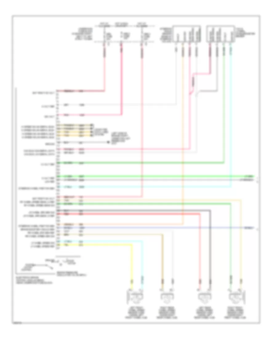
Anti-lock Brakes Wiring Diagram, without VSC (1 of 2) for Pontiac G5 2009
List of elements for Anti-lock Brakes Wiring Diagram, without VSC (1 of 2) for Pontiac G5 2009:
- Abs 2 fuse 10a
- Abs 3 fuse 20a
- Abs fuse 40a
- Bat positive volt
- Brake pressure modulator valve (bpmv)
- Computer data lines system
- Electronic brake control module (ebcm) (near underhood fuse block)
- G101 (left side of engine compt, under coolant reservoir)
- Gnd
- Hi speed gmlan serial bus+
- Hi speed gmlan serial bus-
- Hot at all times
- Hot w/ run/crnk relay energized
- Ign volt
- Left front wheel speed sensor (wss) (inside left front wheel hub)
- Lf wheel speed ref
- Lf wheel speed sig
- Lr wheel spd sen sig
- Lr wheel spd sens lo ref
- Pnk
- Pump motor
- Pump motor control
- Red
- Rf wheel speed sens lo ref
- Rf wheel speed sens sig
- Right front wheel speed sensor (wss) (inside right front wheel hub)
- Right rear wheel speed sensor (wss) (inside right rear wheel hub)
- Rr wheel spd sen ref
- Rr wheel speed sen sig
- Tan
- Underhood fuse block (engine compt, next to left strut tower)
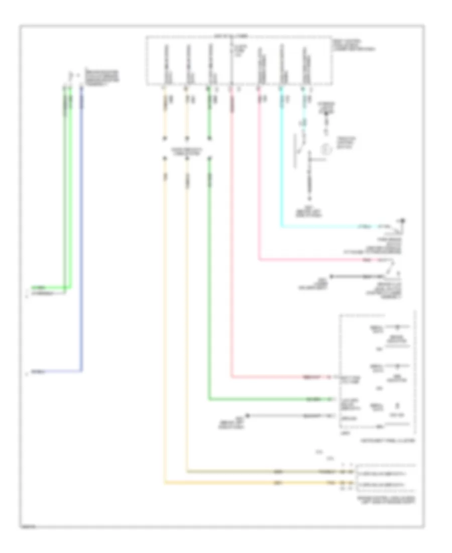
Anti-lock Brakes Wiring Diagram, without VSC (2 of 2) for Pontiac G5 2009
List of elements for Anti-lock Brakes Wiring Diagram, without VSC (2 of 2) for Pontiac G5 2009:
- 2.0l
- 2.2l
- Abs indicator
- Batt pos voltage
- Body control module (bcm) (under center dash)
- Brake fluid level sensor signal
- Brake fluid level switch (master cylinder assembly)
- Brake indicator
- Clstr fuse 10a
- Computer data lines system
- Engine control module (ecm) (left side of engine compt)
- G201 (behind left side of dash)
- G301 (under driver's seat)
- Ground
- Hi spd gmlan ser data +
- Hi spd gmlan ser data -
- Hi spd gmlan serial data +
- Hi spd gmlan serial data -
- Hot at all times
- Ign
- Instrument panel cluster
- Left rear wheel speed sensor (wss) (inside left rear wheel hub)
- Lo spd gmlan serial data
- Logic
- Low spd gmlan ser data
- Park brake switch (center console, attached to parking brake)
- Park brake switch signal
- Pnk
- Red
- Serial data
- Tan
- Vdc ind
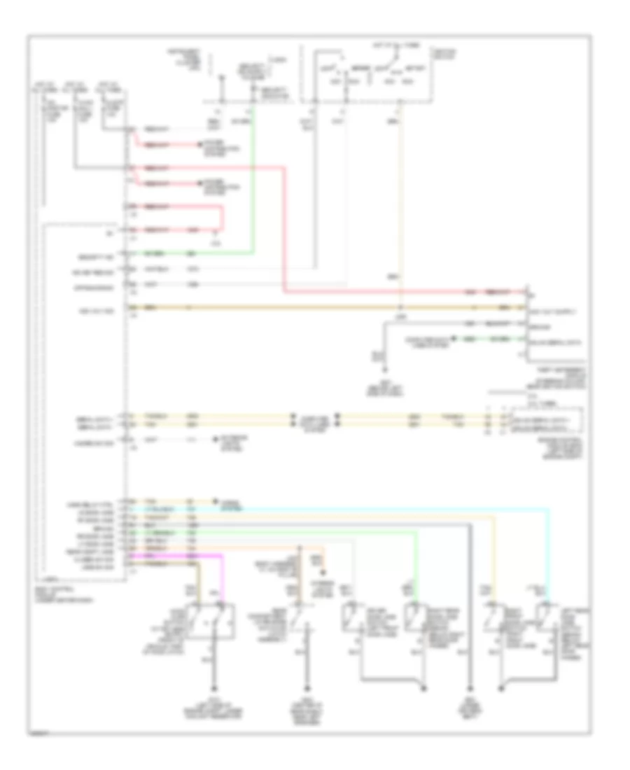
ANTI-THEFT
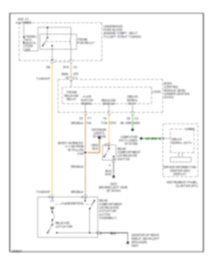
Anti-theft Wiring Diagram for Pontiac G5 2009
List of elements for Anti-theft Wiring Diagram for Pontiac G5 2009:
- 2.0l
- 2.0l turbo
- 2.2l
- Acc
- Acc volt sig
- Body control module (under center dash)
- Closed sw sig
- Clstr fuse 10a
- Computer data lines system
- Driver door jamb switch (left front door jamb)
- Engine control module (ecm) (left side of engine compt)
- Exterior lights system
- G101 (left side of engine compt, under coolant reservoir)
- G201 (behind left side of dash)
- G301 (under driver's seat)
- G401 (center of rear shelf, near left speaker)
- Gmlan serial data
- Gmlan serial data +
- Gmlan serial data -
- Ground
- Hazard sw sig
- Hood ajar switch (w/ keyless entry) (front of vehicle, part of hood latch)
- Horn relay ctrl
- Horns system
- Hot at all times
- Hvac/ pk3 + fuse 10a
- Ign key res sig
- Ignition switch
- Instrument panel cluster (ipc)
- Interior lights system
- J206
- J330 (body harness, 5.1 cm from "b" pillar)
- Jamb sw sig
- Left rear door jamb switch (sedan) (below left rear door hinges)
- Lf door jamb
- Logic
- Lr door jamb
- Off
- Off/run/crank
- Power distribution system
- Rear compartment lid release actuator (latch assembly)
- Rear compt jamb
- Rf door jamb
- Right front door jamb switch (right front door jamb)
- Right rear door jamb switch (sedan) (below right rear door hinges)
- Rr door jamb
- Run
- Security ind
- Security indicator
- Serial data +
- Serial data -
- Start
- Tan
- Theft deterrent module (steering column, near ignition switch)
- Xm/ onstar fuse 10a
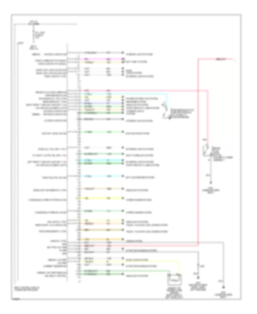
BODY CONTROL MODULES
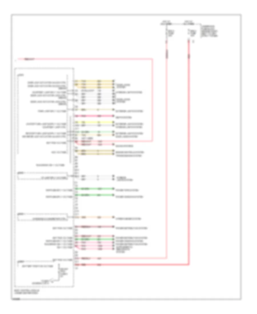
Body Control Modules Wiring Diagram (1 of 4) for Pontiac G5 2009
List of elements for Body Control Modules Wiring Diagram (1 of 4) for Pontiac G5 2009:
- (sedan)
- 5v ref
- A/t shift lk ctrl sol sply vol
- Ambient air temp sens sig
- Ambient air temperature sensor (right side of left headlight)
- Anti-lock brakes system
- Anti-theft system
- Bat pos voltage
- Batt pos vol
- Body control module (under center dash)
- Brake fluid level sens sig
- Brake fluid level switch (master cylinder assembly)
- Chmsl rly coil sply volt
- Computer data lines system
- Coolant level sw sig
- Cooling fans system
- Current sensor sig
- Defogger system
- Door lock lock/unlock sig
- Door locks system
- Drl relay control
- Exterior lights system
- Fog lmp rly ctrl
- G301 (under driver's seat)
- G401 (center of rear shelf, near left speaker)
- Gnd
- Headlamp high beam rly ctrl
- Headlights system
- Hood ajar switch signal
- Hood closed switch signal
- Horn rly ctrl
- Horns system
- Hot at all times
- Int light fuse 27 10a
- Interior lights system
- J352
- Left front turn sig lamp sply vol
- Lf door ajar sw sig
- Logic
- Low ref
- Low spd gmlan serial data
- Lr door ajar sw sig
- Park brake sw sig
- Park brake switch (center console, attached to parking brake)
- Park lamp rly ctrl
- Pnk
- Power distribution system
- Rear compt lid ajar sw sig
- Rear defog rly ctrl
- Rf door ajar sw sig
- Right front turn sig lamp sply vol
- Rr door ajar sw sig
- Run/crank rly coil ctrl
- Shift interlock system
- Starting/charging system
- Tan
- Traction ctrl sw sig
- Trunk release rly ctrl
- Trunk, tailgate, fuel doors system
- Windshield wiper mtr prk sw sig
- Windshield wiper sw on sig
- Wiper/washer system
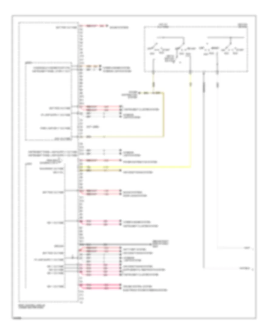
Body Control Modules Wiring Diagram (2 of 4) for Pontiac G5 2009
List of elements for Body Control Modules Wiring Diagram (2 of 4) for Pontiac G5 2009:
- (not used)
- A10
- A11
- A12
- Acc voltage
- B10
- B11
- B12
- Bat pos voltage
- Battery positive voltage
- Bcm 2 fuse 40a
- Bcm 3 fuse 30a
- Body control module (under center dash)
- C10
- C11
- C12
- Courtesy lamp ctrl
- Courtesy lamp sply voltage
- D10
- D11
- D12
- Door lock actuator lock ctrl (sedan)
- Door lock actuator unlock ctrl
- Door lock actuator unlock ctrl (sedan)
- Door locks system
- Driver dr lock actuator unlock ctrl
- Engine controls system
- Exterior lights system
- Hot at all times
- I/p lamp sply voltage
- Ign 1 voltage
- Ign sw/ pk3+ fuse 8 2a
- Interior lights system
- Logic
- Park lamp sply voltage
- Pnk
- Power distribution system
- Power tops system
- Power windows system
- Rap fuse sply voltage
- Red
- Run/crank ign 1 voltage
- Seats system
- Sound systems
- Tan
- To bcm (diagram 3 of 4)
- Transmissions system
- Underhood fuse block (engine compt, next to left strut tower)
- Windshield washer pmp ctrl
- Wiper/washer system
Body Control Modules Wiring Diagram (3 of 4) for Pontiac G5 2009
List of elements for Body Control Modules Wiring Diagram (3 of 4) for Pontiac G5 2009:
- (behind right side of dash) g203
- (not used)
- A10
- A11
- A12
- Acc
- Acc voltage
- Air conditioning system
- Anti-theft system
- B10
- B11
- B12
- Bat pos voltage
- Body control module (under center dash)
- C10
- C11
- C12
- Cruise control system
- D10
- D11
- D12
- Door locks system
- E10
- E11
- E12
- Electronic power steering system
- F10
- F11
- F12
- From bcm a (diagram 2 of 4)
- Ground
- Hot at all times
- Ign 1 voltage
- Ign 3 vol
- Ign voltage
- Ignition switch
- Instrument cluster system
- Instrument panel lp sply volt
- Interior lights system
- J206
- Key-in ignition switch
- Logic
- Off
- Park lamp sply voltage
- Pnk
- Power distribution system
- Run
- Run/crank voltage
- Sound systems
- Start
- Windshield washer pump ctrl
- Wiper/washer system
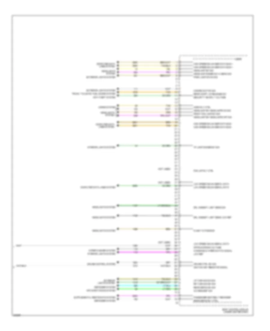
Body Control Modules Wiring Diagram (4 of 4) for Pontiac G5 2009
List of elements for Body Control Modules Wiring Diagram (4 of 4) for Pontiac G5 2009:
- (not used)
- A/c request sig
- Air conditioning system
- Anti-theft system
- Body control module (under center dash)
- Computer data lines system
- Cruise control system
- Cruise ctrl sw sig
- Defogger system
- Drl ambient light sens low ref
- Drl ambient light sens sig
- Exterior lights system
- Flash to pass sig
- Fog lmp rly ctrl
- Front fog lamp sw sig
- Hazard switch sig
- Headlamp dimmer sw hi beam sig
- Headlamp sw headlamps off sig
- Headlamp sw headlamps on sig
- Headlamp sw sig
- Headlights system
- High speed gmlan ser data bus +
- High speed gmlan ser data bus -
- Horn rly ctrl
- Horns system
- I/p lamp dimmer sw sig
- Ignition key resistor signal
- Interior lights system
- Logic
- Low ref
- Low speed gmlan serial data
- Lr turn sig sw sig
- Off/run/crank voltage
- Park lamp sw on sig
- Passenger seatbelt reminder
- Rear compt lid release sw
- Rear defog rly ctrl
- Rear defog sw sig
- Rr turn sig sw sig
- Security ind sply voltage
- Tan
- Trunk, tailgate, fuel doors system
- Windshield wiper switch signal
- Wiper/washer system
COMPUTER DATA LINES
Computer Data Lines Wiring Diagram for Pontiac G5 2009
List of elements for Computer Data Lines Wiring Diagram for Pontiac G5 2009:
- (behind left side of dash) g201
- (under dash, near base of steering column) electronic power steering (eps) control module
- 2.0l
- 2.0l/2.2l m/t
- 2.2l
- 2.2l a/t
- Body control logic
- Data link connector (dlc) (lower left of of dash)
- Digital radio receiver (center rear shelf, under trim pad)
- Display
- Dlc fuse 15a
- Electronic brake control module (ebcm) (w/ abs) (near underhood fuse block)
- Engine control module (ecm) (2.0l/2.2l) (left side of engine compt)
- Engine control module (ecm) (2.2l) (left side of engine compt)
- G203 (behind right side of dash)
- High speed gmlan serial data bus +
- High speed gmlan serial data bus -
- Hot at all times
- If equipped
- Inflatable restraint sensing & diagnostic module (sdm) (under center console)
- Instrument panel cluster (ipc)
- Jx200 (lower left of dash, below hood release)
- Low speed gm lan serial data
- Low speed gmlan serial data
- Module (bcm) (under center dash)
- Not used
- Radio
- Remote control door lock receiver (rcdlr) (under right dash trim panel)
- Serial data bus + high speed gmlan
- Serial data bus - high speed gmlan
- Tan
- Theft deterrent module (tdm) (steering column, near ignition switch)
- Transmission control module (tcm) (left rear of engine compt)
- Underhood fuse block (engine compt, next to left strut tower)
- Vehicle communication interface module (vcim) (under rear, shelf between speakers)
- W/ active brake
- W/ multi info display
- W/ onstar
- W/ vsc
- W/o active brake
- W/o multi info display
- W/o onstar
- W/o vsc
COOLING FAN
2.0L VIN X
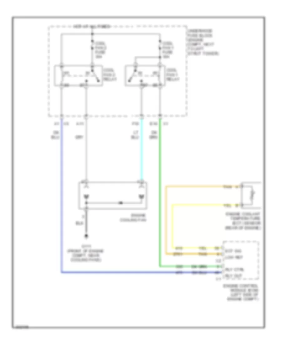
2.0L VIN X, Cooling Fan Wiring Diagram for Pontiac G5 2009
List of elements for 2.0L VIN X, Cooling Fan Wiring Diagram for Pontiac G5 2009:
- 87a
- A1 x5
- A11 x1
- Body control module (bcm) (under center dash)
- Computer data lines system
- Cool fan 1 fuse 30a
- Cool fan 1 relay
- Cool fan 2 fuse 30a
- Cool fan 2 relay
- Cool fans relay
- Coolant level ind
- Coolnt sw
- Ect sig
- Engine control module (ecm) (left side of engine compt)
- Engine coolant level switch (left side of engine compt, on bottom of coolant reservoir)
- Engine coolant temperature (ect) sensor (right rear of engine block)
- F10
- F2 x3
- G101 (left side of engine compt, under coolant reservoir)
- G111 (front of engine compt, near cooling fans)
- G301 (under driver's seat)
- Hot at all times
- Instrument panel cluster (ipc)
- Left engine cooling fan
- Logic
- Low ref
- Low spd gmlan serial data
- Right engine cooling fan
- Rly ctrl
- Serial data (+)
- Serial data (-)
- Tan
- Underhood fuse block (engine compt, next to left strut tower)
- X1 a6
- X1 e10
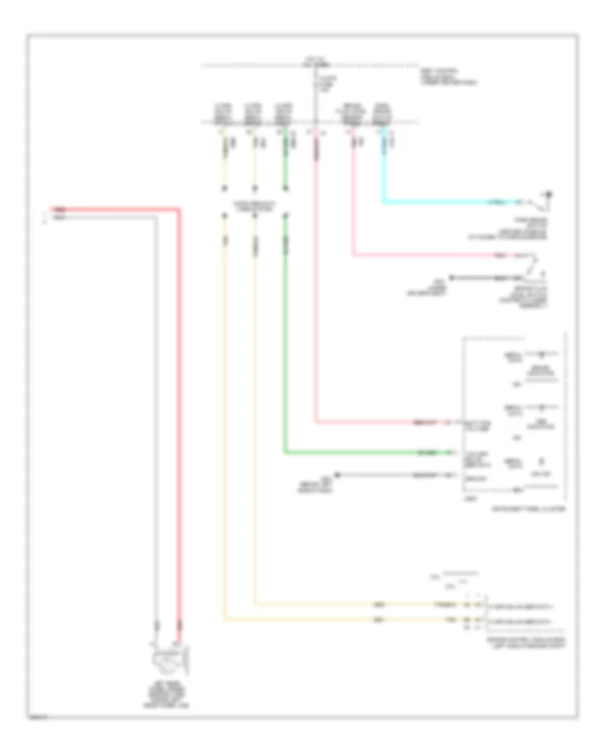
2.2L VIN H
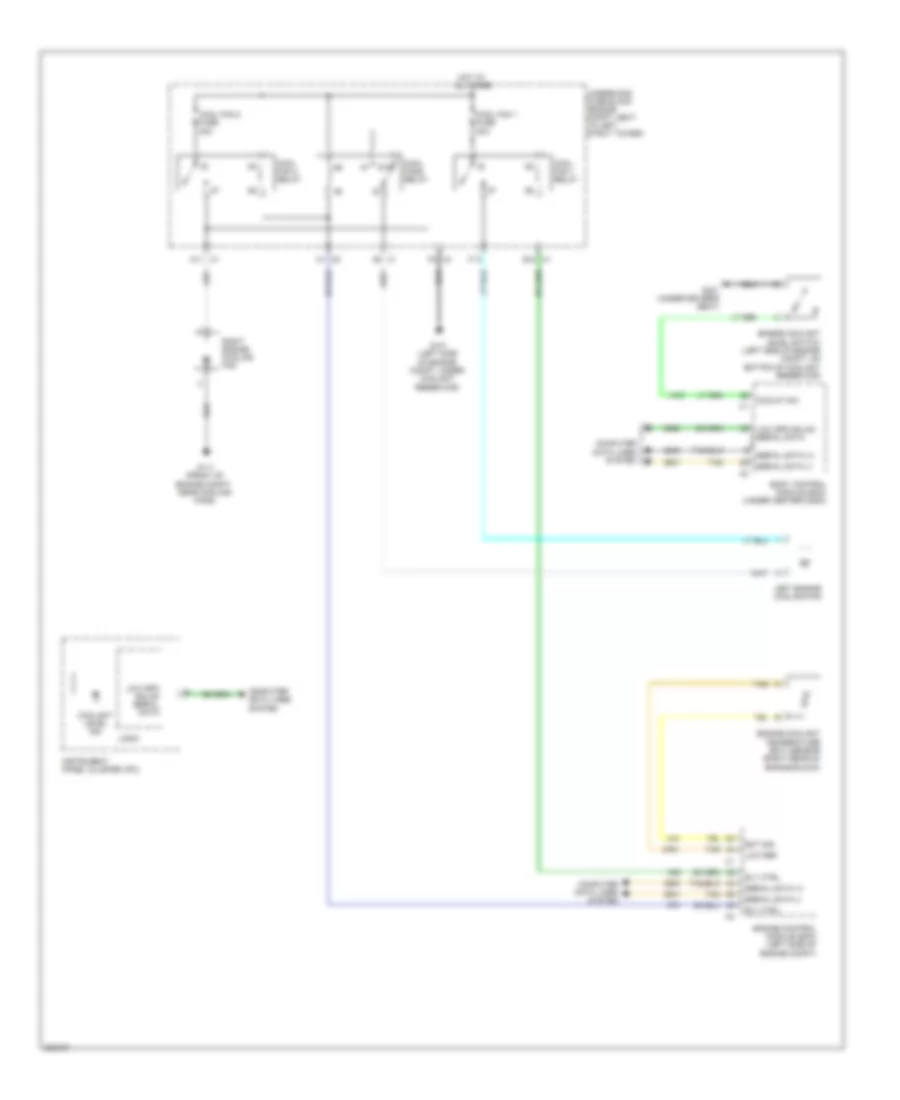
2.2L VIN H, Cooling Fan Wiring Diagram for Pontiac G5 2009
List of elements for 2.2L VIN H, Cooling Fan Wiring Diagram for Pontiac G5 2009:
- A1 x5
- A11
- Cool fan 1 fuse 30a
- Cool fan 1 relay
- Cool fan 2 fuse 30a
- Cool fan 2 relay
- E10
- Ect sig
- Engine control module (ecm) (left side of engine compt)
- Engine coolant temperature (ect) sensor (rear of engine)
- Engine cooling fan
- F10
- G111 (front of engine compt, near cooling fans)
- Hot at all times
- Low ref
- Rly ctrl
- Rly out
- Tan
- Underhood fuse block (engine compt, next to left strut tower)
CRUISE CONTROL
Cruise Control Wiring Diagram, A/T for Pontiac G5 2009
List of elements for Cruise Control Wiring Diagram, A/T for Pontiac G5 2009:
- 5 volt ref
- 5 volt ref 2
- 5v ref 2
- Acc volt
- Accelerator pedal position (app) sensor (near accelerator pedal bracket)
- App sens 1 sig
- App sens 2 sig
- Automatic transmission
- B5 x3
- Body control module (under center dash)
- Computer data lines system
- Cruise control on ind
- Cruise ctrl sw sig
- Data bus +
- Data bus -
- Engine control module (ecm) (left side of engine compartment)
- Eps/ str whl cntrl fuse 19 2a
- G105 (lower left front of transmission case)
- G201 (behind left side of dash)
- Gnd
- Hot w/ run/crank relay energized
- Inflatable restraint steering wheel module coil (steering column, behind steering wheel)
- J208
- Left steering wheel control switch
- Logic
- Low ref
- Pnk
- Power distribution system
- Res +
- Set -
- Tac mtr ctrl 1
- Tac mtr ctrl 2
- Tan
- Throttle body (intake manifold assembly)
- Tp sens 1 sig
- Tp sens 2 sig
- Transmission control module (tcm) (left rear of engine compt)
- Vehicle speed sensor (vss)
- Vss high sig
- Vss low sig
Cruise Control Wiring Diagram, M/T for Pontiac G5 2009
List of elements for Cruise Control Wiring Diagram, M/T for Pontiac G5 2009:
- (lower left front of transmission case) g105
- (or 6354)
- (or 6356)
- (or 7360)
- (or 7361)
- (steering column, behind steering wheel) inflatable restraint steering wheel module coil
- 2.0l
- 2.2l
- 5 volt ref
- 5 volt ref 1
- 5 volt ref 2
- 5v ref 2 x1
- Acc volt
- Accelerator pedal position (app) sensor (near accelerator pedal bracket)
- App sens 1 sig
- App sens 2 sig
- Body control module (under center dash)
- Clutch pedal position (cpp) sensor (top of clutch pedal)
- Computer data lines system
- Cpp sens sig
- Cruise control on ind
- Cruise ctrl sw sig
- Data bus +
- Data bus -
- Engine control module (ecm) (left side of engine compartment)
- Engine controls system
- Eps/ str whl cntrl fuse 19 2a
- G201 (behind left side of dash)
- Gnd
- Hot w/ run/crank relay energized
- J150 (2.0l)
- J208
- J310 (2.0l)
- J311 tan (2.0l)
- Left steering wheel control switch
- Logic
- Low ref
- Pnk
- Power distribution system
- Res+
- Set-
- Tac mtr ctrl 1
- Tac mtr ctrl 2
- Tan
- Throttle actuator control (tac) module (2.0l) (intake manifold assembly)
- Throttle body (2.2l) (intake manifold assembly)
- Tp sens 1 sig
- Tp sens 2 sig
- Vehicle speed sensor (top of transaxle)
- Vss high sig
- Vss low sig
- X3 b5
DEFOGGERS
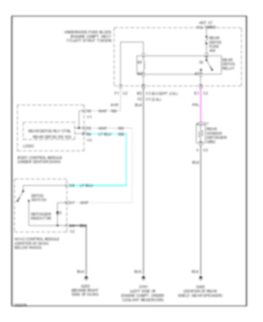
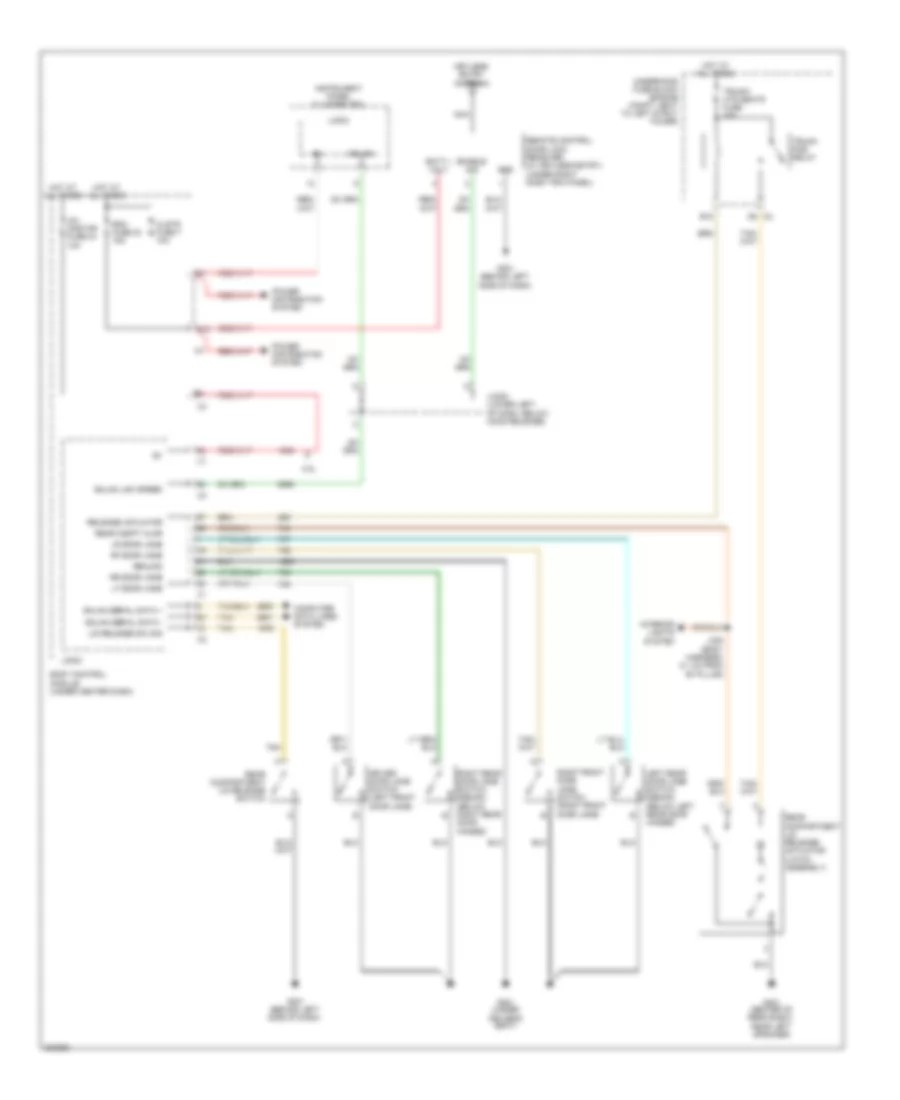
Defoggers Wiring Diagram for Pontiac G5 2009
List of elements for Defoggers Wiring Diagram for Pontiac G5 2009:
- (2.0l)
- (except 2.0l)
- Body control module (under center dash)
- Defog switch
- Defogger indicator
- G101 (left side of engine compt, under coolant reservoir)
- G203 (behind right side of dash)
- G402 (center of rear shelf, near speaker)
- Hot at all times
- Hvac control module (center of dash, below radio)
- Logic
- Rear defog fuse 40a
- Rear defog relay
- Rear defog rly ctrl
- Rear defog sw sig
- Rear window defogger grid
- Underhood fuse block (engine compt, next to left strut tower)
- X2 a
- X2 e1
- X2 f1
- X3 b2
- X3 f2
ELECTRONIC POWER STEERING
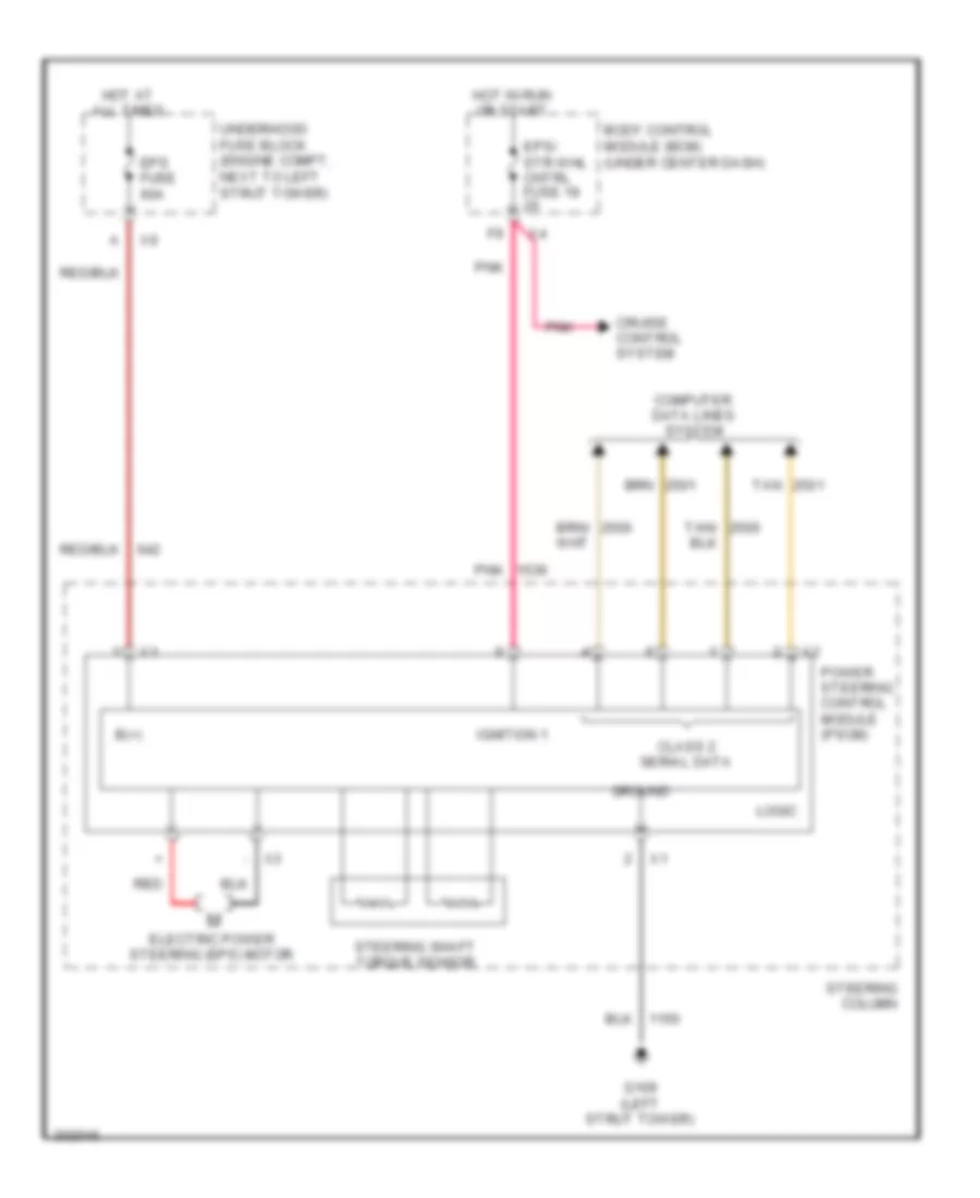
Electronic Power Steering Wiring Diagram for Pontiac G5 2009
List of elements for Electronic Power Steering Wiring Diagram for Pontiac G5 2009:
- - x3
- B(+)
- Body control module (bcm) (under center dash)
- Class 2 serial data
- Computer data lines system
- Cruise control system
- Electric power steering (eps) motor
- Eps fuse 60a
- Eps/ str whl cntrl fuse 19 2a
- G109 (left strut tower)
- Ground
- Hot at all times
- Hot in run or start
- Ignition 1
- Logic
- Pnk
- Power steering control module (pscm)
- Red
- Steering column
- Steering shaft torque sensor
- Tan
- Tan/
- Underhood fuse block (engine compt, next to left strut tower)
ENGINE PERFORMANCE
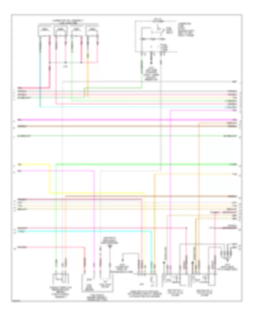
2.2L VIN H
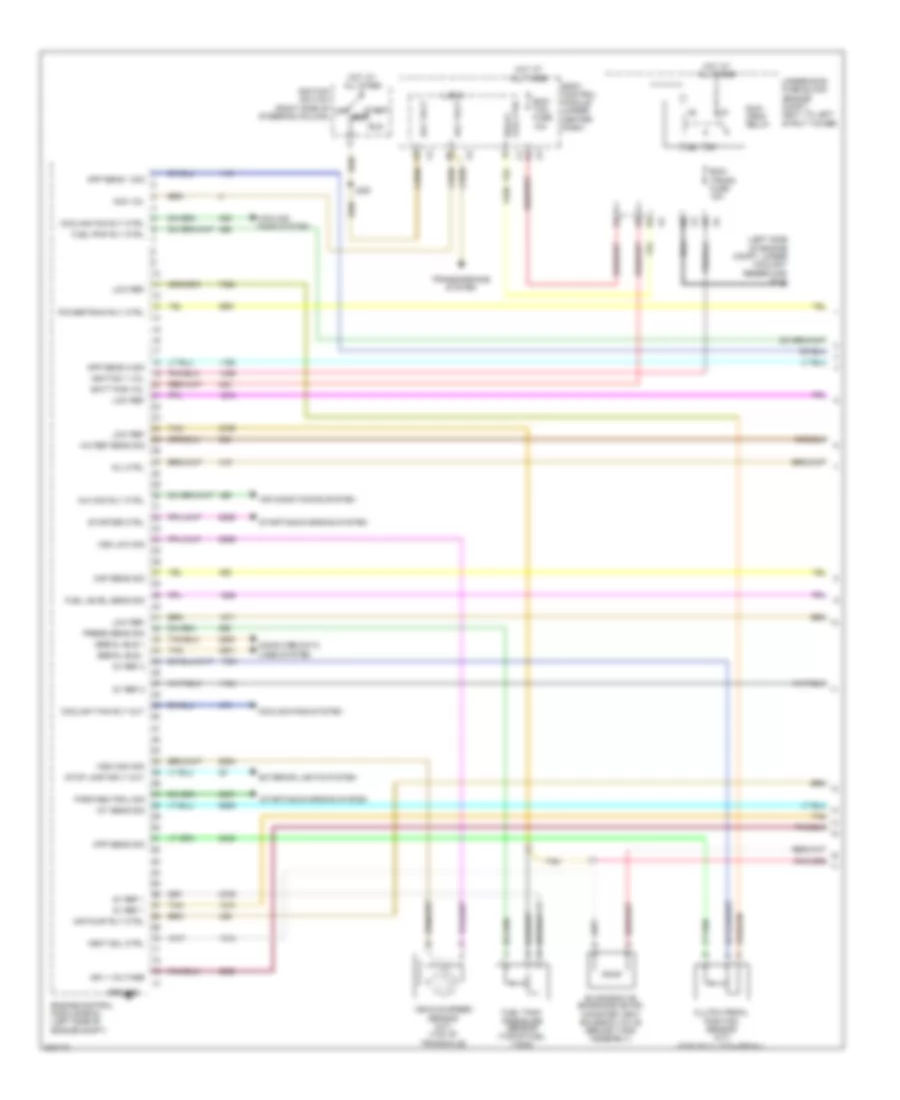
2.2L VIN H, Engine Performance Wiring Diagram (1 of 4) for Pontiac G5 2009
List of elements for 2.2L VIN H, Engine Performance Wiring Diagram (1 of 4) for Pontiac G5 2009:
- (left side of engine compt, under coolant reservoir) g101
- 5v ref 1
- 5v ref 2
- A/c com rly ctrl
- A/c ref sens sig
- Acc
- Acc vol
- Acc volt
- Air conditioning system
- Air pump rly ctrl
- App sens 1 sig
- App sens 2 sig
- Batt pos vol
- Body control module (under center dash)
- Clutch pedal position sensor (m/t) (top of clutch pedal)
- Computer data lines system
- Coolant fan rly out
- Cooling fan rly ctrl
- Cooling fans system
- Cpp sens sig
- Ecm/ tcm fuse 10a
- Ecm/ trans fuse 15a
- Engine control module (ecm) (left side of engine compt)
- Evaporative emissions (evap) canister vent solenoid valve (behind tank assembly)
- Exterior lights system
- Fuel level sens sig
- Fuel pmp rly ctrl
- Fuel tank pressure sensor (top of fuel tank)
- Ground
- Hot at all times
- Iat sens sig
- Ign 1 voltage
- Ignition 1 vol
- Ignition switch (right side of steering column)
- J206
- Logic
- Low ref
- Maf sens sig
- Mil ctrl
- Off
- Park/neutral sig
- Powertrain rly ctrl
- Press sens sig
- Relay coil ctrl
- Run
- Run/ crnk relay
- Serial bus +
- Serial bus -
- Start
- Starter ctrl
- Starting/charging system
- Stop lamp sply out
- Tan
- Transmissions system
- Underhood fuse block (engine compt, next to left strut tower)
- Vehicle speed sensor (m/t) (top of transaxle)
- Vent sol ctrl
- Vss high sig
- Vss low sig
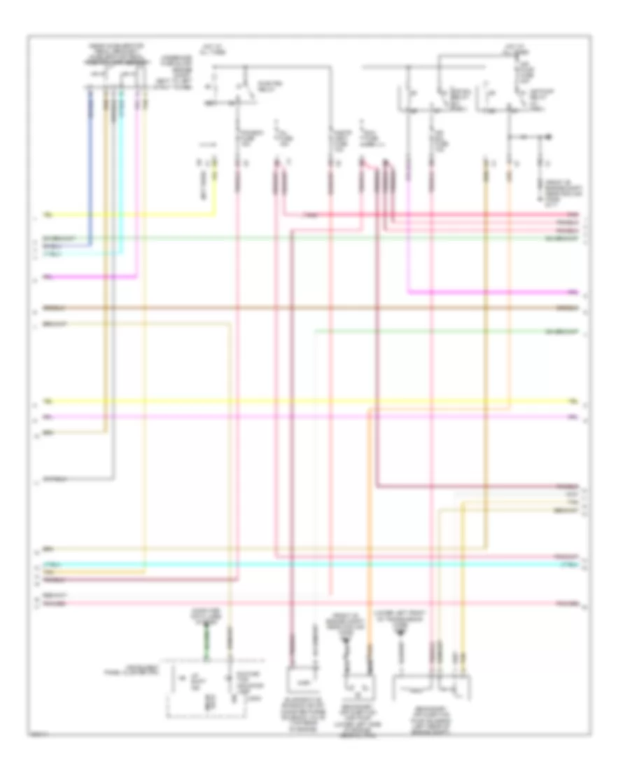
2.2L VIN H, Engine Performance Wiring Diagram (2 of 4) for Pontiac G5 2009
List of elements for 2.2L VIN H, Engine Performance Wiring Diagram (2 of 4) for Pontiac G5 2009:
- (front of engine compt, near cooling fans) g111
- (lower left front of transmission case) g105
- (near accelerator pedal bracket) accelerator pedal position (app) sensor
- (not used)
- Air pump fuse 40a
- Air pump relay (w/ pzev)
- Air sol fuse 10a
- Air sol relay (w/ pzev)
- B11
- Cnstr vent fuse 10a
- Computer data lines system
- Data gmlan
- Evaporative emission (evap) canister purge solenoid valve (top,rear of engine)
- Exh fuse 10a
- Hot at all times
- Ign
- Inj fuse 15a
- Instrument panel cluster (ipc)
- Logic
- Malfunc- tion indicator lamp
- Nca
- Pcm/ecm fuse 15a
- Pnk
- Pwr/trn relay
- Secondary air injection (air) pump (lower left side of engine, near oil pan)
- Secondary air injection pump solenoid (left rear of engine compt)
- Tan
- Underhood fuse block (engine compt, next to left strut tower)
- Up shift ind
2.2L VIN H, Engine Performance Wiring Diagram (3 of 4) for Pontiac G5 2009
List of elements for 2.2L VIN H, Engine Performance Wiring Diagram (3 of 4) for Pontiac G5 2009:
- (center of rear shelf, near speaker) g402
- (under fuel rail assembly) fuel injectors
- Fuel level sensor
- Fuel pump & sender assembly (inside fuel tank)
- Fuel pump fuse 15a
- Fuel pump motor
- Fuel pump relay
- G101 (left side of engine compt, under coolant reservoir)
- G105 (lower left front of transmission case)
- G107 (right rear of cylinder head)
- Hot at all times
- Iat
- Ignition coil 1 (top of valve cover)
- Ignition coil 2 (top of valve cover)
- J103
- J141
- Maf
- Manifold absolute pressure (map) sensor (throttle body assembly)
- Mass air flow (maf)/inlet air temperature (iat) sensor (intake,after air cleaner)
- Pnk
- Spark plug
- Tan
- Underhood fuse block (engine compt, next to left strut tower)
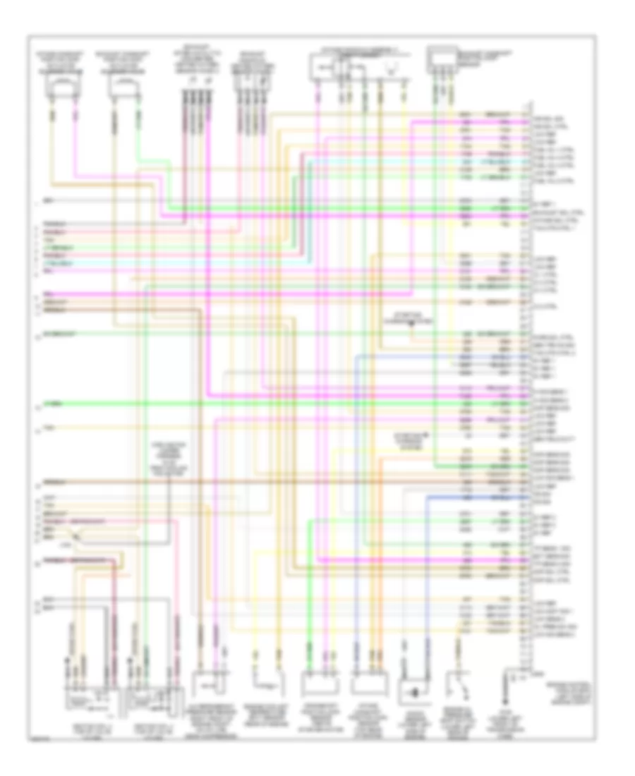
2.2L VIN H, Engine Performance Wiring Diagram (4 of 4) for Pontiac G5 2009
List of elements for 2.2L VIN H, Engine Performance Wiring Diagram (4 of 4) for Pontiac G5 2009:
- (cooling fan jumper harness, 15 cm from cooling fan motor)
- (exhaust manifold) heated oxygen sensor (ho2s) 1
- (exhaust, after catalytic converter) heated oxygen sensor (ho2s) 2
- (intake manifold assembly) throttle body
- 5v ref
- 5v ref 1
- 5v ref 2
- A/c refrigerant pressure sensor (right front of engine compt, on a/c line, near compressor)
- Air sol ctrl
- Air sol sig
- Ckp sens sig
- Cmp sens sig
- Cmp sol ctrl
- Crankshaft position (ckp) sensor (above starter motor)
- Ect sens sig
- Engine control module (ecm) (left side of engine compt)
- Engine coolant temperature (ect) sensor (rear of engine)
- Engine oil pressure (eop) switch (lower left rear of engine)
- Exhaust camshaft position (cmp) actuator solenoid valve
- Exhaust camshaft position (cmp) sensor
- Exhaust sol ctrl
- Fuel inj 1 ctrl
- Fuel inj 2 ctrl
- Fuel inj 3 ctrl
- Fuel inj 4 ctrl
- G105 (lower left front of transmission case)
- Gen field duty
- Gen trn on sig
- Gnd
- Hi sig sens 1
- Hi sig sens 2
- Ic 1 ctrl
- Ic 2 ctrl
- Ic 3 ctrl
- Ic 4 ctrl
- Ignition coil 3 (top of valve cover)
- Ignition coil 4 (top of valve cover)
- Intake camshaft position (cmp) actuator solenoid valve
- Intake camshaft position (cmp) sensor (top rear of engine)
- Intake sol ctrl
- J105
- Knock sensor (lower left side of engine)
- Ks sig
- Loc cont sig 1
- Low ref
- Low sens 2
- Low sig sens 1
- Low sig sens 2
- Map sens sig
- Nca
- Oil pres sw sig
- Purg sol ctrl
- Spark plug
- Starting/ charging system
- Tac mtr ctrl 1
- Tac mtr ctrl 2
- Tan
- Tp sens 1 sig
- Tp sens 2 sig
EXTERIOR LIGHTS
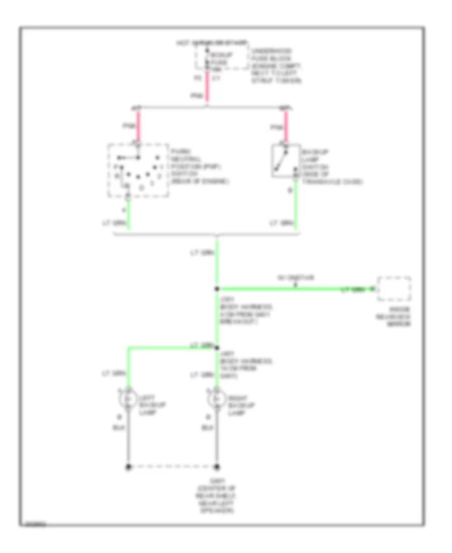
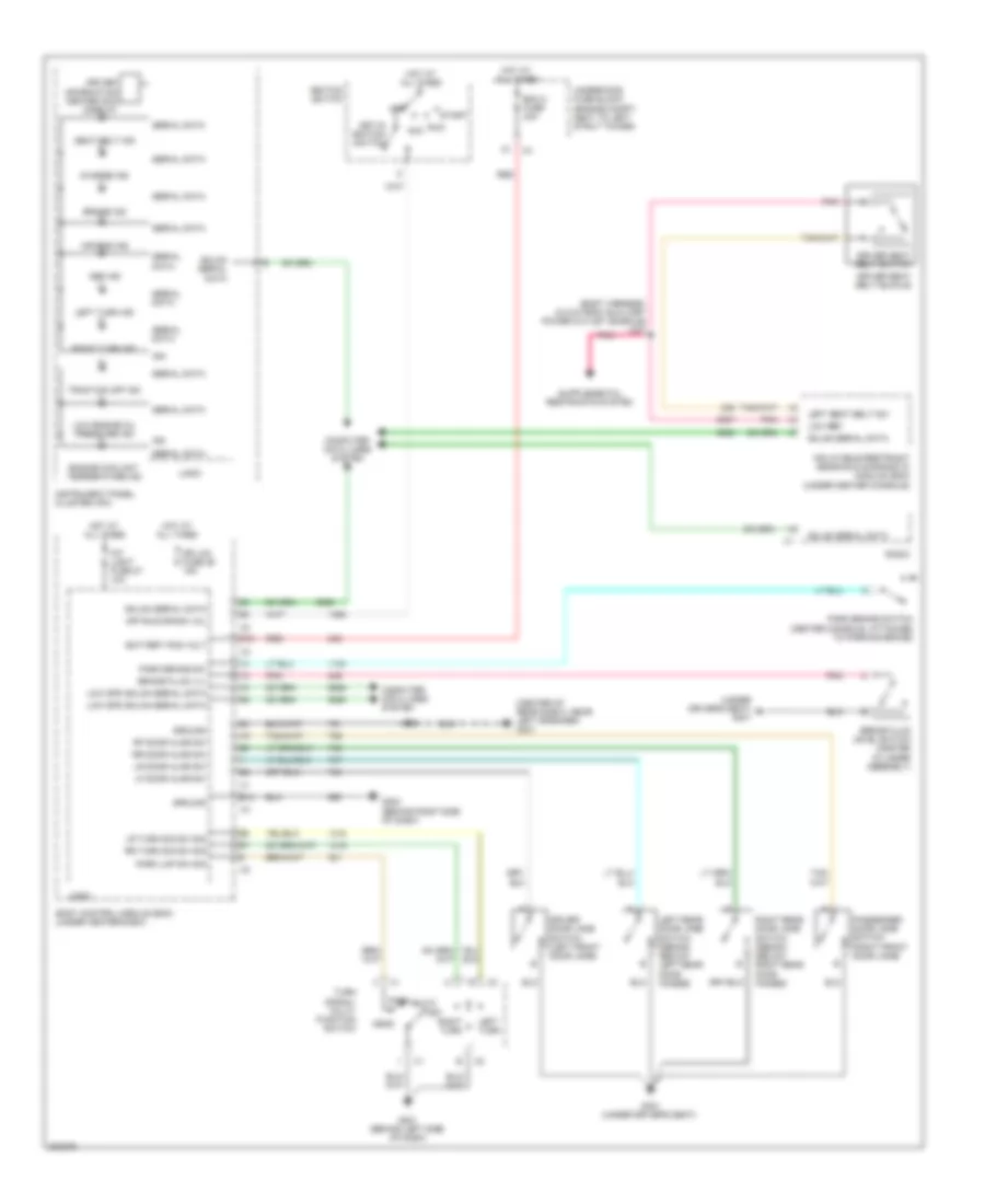
Backup Lamps Wiring Diagram for Pontiac G5 2009
List of elements for Backup Lamps Wiring Diagram for Pontiac G5 2009:
- A/t
- Backup lamp switch (side of transaxle case)
- Bckup fuse 10a
- G401 (center of rear shelf, near left speaker)
- Hot in run or start
- Inside rearview mirror
- J351 (body harness, 4 cm from g401 breakout)
- J401 (body harness, 14 cm from g401)
- Left backup lamp
- M/t
- Park/ neutral position (pnp) switch (rear of engine)
- Pnk
- Right backup lamp
- Underhood fuse block (engine compt, next to left strut tower)
- W/ onstar
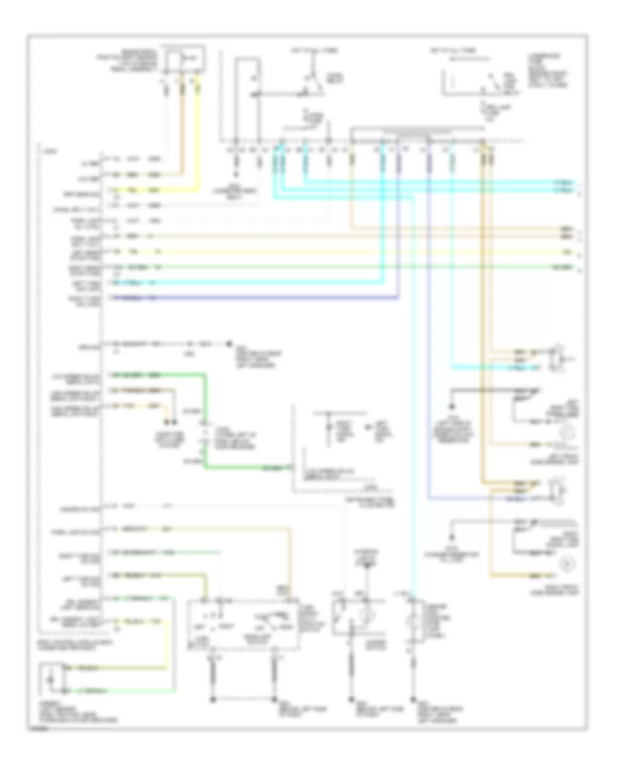
Exterior Lamps Wiring Diagram (1 of 2) for Pontiac G5 2009
List of elements for Exterior Lamps Wiring Diagram (1 of 2) for Pontiac G5 2009:
- 5v ref
- A12
- Ambient light sensor (dash trim pad, near windshield on driver's side)
- Auto
- Body control module (bcm) (under center dash)
- Bpp sens sig
- Brake pedal position (bpp) sensor (top of brake pedal assembly)
- Center high mounted stop lamp (chmsl)
- Chmsl fuse 10a
- Chmsl relay
- Chmsl sply volt
- Computer data lines system
- Drl ambient light sens low ref
- Drl ambient light sens sig
- F5 x2
- G101 (left side of engine compt, under coolant reservoir)
- G102 (washer reservoir fill cap)
- G201 (behind left side of dash)
- G301 (under driver's seat)
- G401 (center of rear shelf, near left speaker)
- Ground
- Hazard sw sig
- Hazard switch
- Head
- Headlamp switch
- High speed gmlan serial data bus +
- High speed gmlan serial data bus -
- Hot at all times
- Instrument panel cluster (ipc)
- Interior lights system
- J352
- Jx200 (lower left of dash, below hood release)
- Left
- Left front side marker lamp
- Left park/turn signal lamp
- Left rear stop/turn
- Left turn sig lamp
- Left turn sig sw sig
- Left turn signal ind
- Logic
- Low ref
- Low speed gmlan serial data
- Off
- Park
- Park lamp rly ctrl
- Park lamp sply volt
- Park lamp sw sig
- Prk lamp fuse 10a
- Prk lamp pcb relay
- Right
- Right front side marker lamp
- Right park/turn signal lamp
- Right rear stop/turn
- Right turn sig lamp
- Right turn sig sw sig
- Right turn signal ind
- Tan
- Turn signal/ multi- function switch
- Turn switch
- Underhood fuse block (engine compt, next to left strut tower)
- X1 b5
- X2 b7
- X2 e9
- X5 c2
Exterior Lamps Wiring Diagram (2 of 2) for Pontiac G5 2009
List of elements for Exterior Lamps Wiring Diagram (2 of 2) for Pontiac G5 2009:
- (2.0l)
- (2.2l)
- (body harness, 3.75 cm from g301) j361
- Coupe
- Engine control module (ecm) (left side of engine compt)
- G401 (center of rear shelf, near left speaker)
- G402 (center of rear shelf, near speaker)
- Left backup lamp
- Left rear side marker lamp
- Left tail/ stop & turn signal lamp
- License lamp
- Right backup lamp
- Right rear side marker lamp
- Right tail/ stop & turn signal lamp
- Sedan
- Stop lamp sw sig
- Transmission control module (tcm) (left rear of engine compt)
GROUND DISTRIBUTION
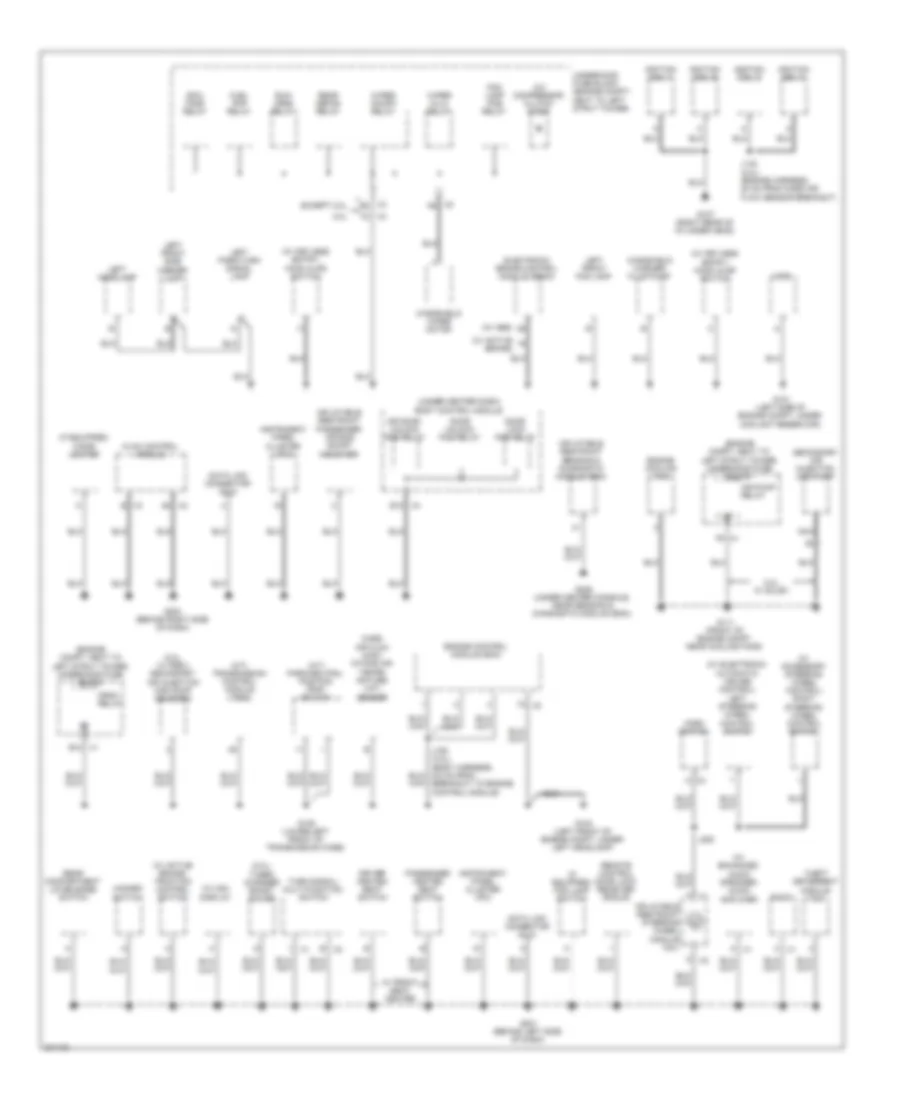
Ground Distribution Wiring Diagram (1 of 2) for Pontiac G5 2009
List of elements for Ground Distribution Wiring Diagram (1 of 2) for Pontiac G5 2009:
- (2.0l) turbo charger boost gauge
- (2.2l, w/ pzev) secondary air injection (air) pump solenoid
- (a/t) park/neutral position (pnp) switch
- (a/t) transmission control module (tcm)
- (engine compt, next to left strut tower) underhood fuse block
- (if equipped) cigar lighter
- (if equipped) fog lamp switch
- (under center dash) body control module
- (w/ abs)
- (w/ accessory steering wheel control) right steering wheel control switch
- (w/ active brake)
- (w/ active brake) traction control switch
- (w/ electronic automatic cruise control) left steering wheel control switch
- (w/ enhanced audio speaker) audio amplifier
- (w/ keyless entry) hood ajar switch
- (w/ mid) display
- 2.0l
- 2.2l, w/ sulev
- A/c compressor clutch diode
- A5 x2
- Air pump relay
- B x2
- B x3
- Cool fans relay
- Crnk relay
- Data link connector (dlc)
- Door lock pcb relay
- Door unlock pcb relay
- Dr door unlock pcb relay
- Driver heated seat switch
- E12
- Electronic brake control module (ebcm)
- Engine control module (ecm)
- Engine cooling fan
- Except 2.0l
- Fog lamp pcb relay
- Fuel pmp relay
- G101 (left side of engine compt, under coolant reservoir)
- G103 (left front of engine compt, under left headlamp)
- G105 (lower left front of transmission case)
- G107 (right rear of cylinder head)
- G111 (front of engine compt, near cooling fans)
- G201 (behind left side of dash)
- G203 (behind right side of dash)
- G306 (under center console, near sensing & diagnostic module (sdm))
- Hazard switch
- Horn
- Horn switch
- Hvac control module
- Ignition coil 1
- Ignition coil 2
- Ignition coil 3
- Ignition coil 4
- Inflatable restraint passenger air bag on/off indicator
- Inflatable restraint sensing & diagnostic module (sdm)
- Inflatable restraint steering wheel module coil
- Instrument panel cluster (ipc)
- J142 (2.0l) (engine harness, 20 cm from mass air flow sensor breakout)
- J150 (2.0l) (body harness, 9.5 cm from breakout to engine control module)
- J208
- K x1
- K x2
- Left front fog lamp
- Left front side marker lamp
- Left headlamp
- Left park/turn signal lamp
- Mass air flow (maf)/ intake air tempe- rature (iat) sensor
- Nca
- Passenger heated seat switch
- Radio
- Rear compartment lid release switch
- Rear defog relay
- Remote control door lock receiver (rcdlr)
- Run/ crnk relay
- Secondary air injection (air) pump
- Theft deterrent module (tdm)
- Turn signal/ multi-function switch
- Underhood fuse block (engine compt, next to left strut tower)
- W/ front seat heater
- Windshield washer fluid pump
- Windshield wiper motor
- Wiper hi/lo relay
- Wiper on/off relay
- X1 b12
- X2 a
- X2 a6
- X3 b2
- X3 f2
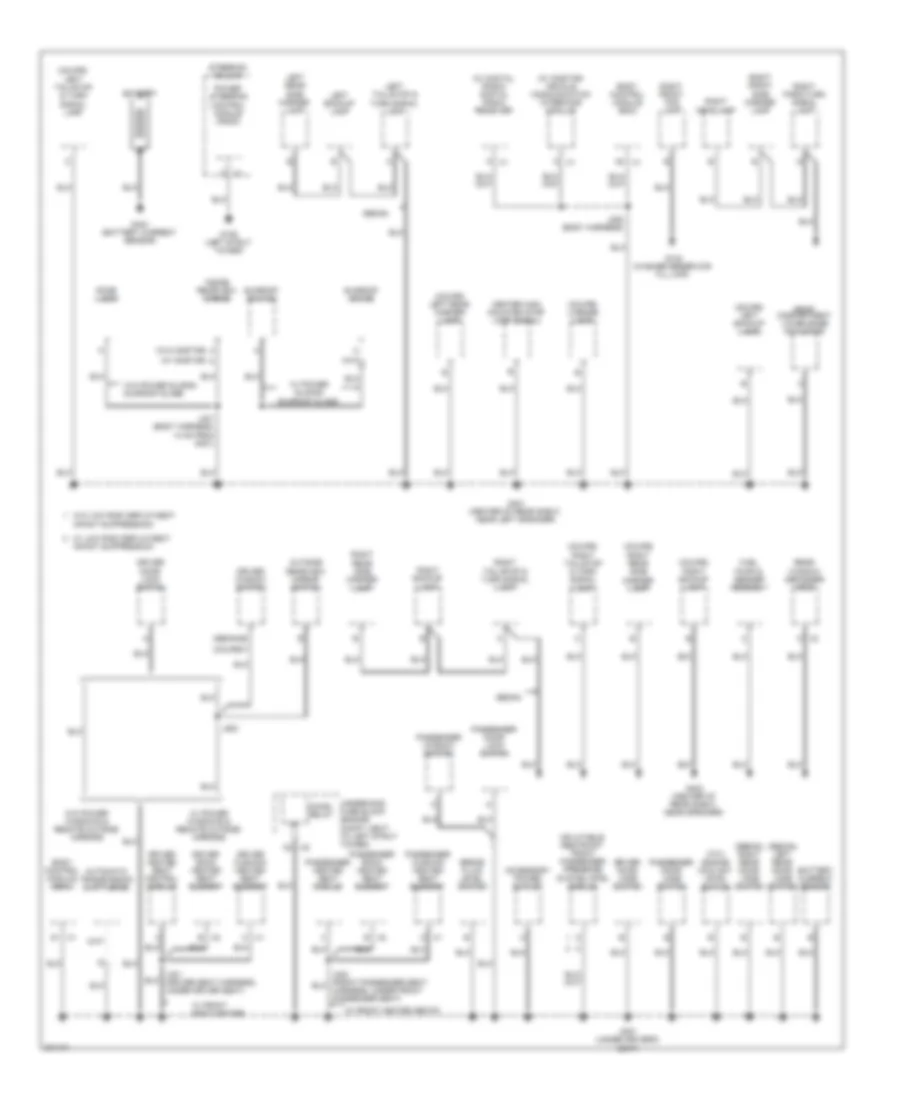
Ground Distribution Wiring Diagram (2 of 2) for Pontiac G5 2009
List of elements for Ground Distribution Wiring Diagram (2 of 2) for Pontiac G5 2009:
- (2.0l) engine coolant level switch
- (coupe) f
- (coupe) left backup lamp
- (coupe) left rear marker lamp
- (coupe) left tail/stop & turn signal lamp
- (coupe) license lamp
- (coupe) right backup lamp
- (coupe) right rear side marker lamp
- (coupe) right tail/stop & turn signal lamp
- (sedan) b
- (sedan) left rear door jamb switch
- (sedan) right rear door jamb switch
- (w/ digital radio) digital radio receiver
- (w/ onstar)
- (w/ onstar) vehicle communication interface module
- (w/o onstar)
- A x2
- Accessory power outlet
- Automatic transmission shift lever
- B x2
- Battery
- Battery current sensor
- Body control module (bcm)
- Brake fluid level switch
- C x1
- C2 x5
- Center high mounted stop lamp (chmsl)
- Chmsl relay
- Dome lamp
- Driver back heated seat element
- Driver cushion heated seat element
- Driver door jamb switch
- Driver door lock switch
- Driver heated seat control module
- Driver window switch
- Fuel pump & sender assembly
- G102 (washer reservoir fill cap)
- G109 (left strut tower)
- G301 (under driver's seat)
- G401 (center of rear shelf, near left speaker)
- G402 (center of rear shelf, near speaker)
- G403 (battery current sensor)
- Infant suppression
- Inflatable restraint front passenger presence system (pps) module
- Inside rearview mirror
- J301 (driver seat harness, under driver seat)
- J352 (body harness)
- J401 (body harness, 14 cm from g401)
- J500
- Left backup lamp
- Left rear side marker lamp
- Left tail/stop & turn signal lamp
- Outside rearview mirror switch
- Passenger back heated seat element
- Passenger cushion heated seat element
- Passenger door jamb switch
- Passenger door lock switch
- Passenger heated seat module
- Passenger window switch
- Power steering control module (pscm)
- Rear compartment lid release actuator
- Rear window defogger grid
- Right backup lamp
- Right front fog lamp
- Right front side marker lamp
- Right headlamp
- Right park/turn signal lamp
- Right rear side marker lamp
- Right tail/stop & turn signal lamp
- Sedan
- Steering column
- Sunroof motor
- Sunroof switch
- Underhood fuse block (engine compt, next to left strut tower)
- W/ front heated seats
- W/ front seat heater
- W/ low risk deployment
- W/ power sliding sunroof glass
- W/ power windows & remote outside mirrors
- W/o low risk deployment infant suppression
- W/o power sliding sunroof glass
- W/o power windows & remote outside mirrors
HEADLIGHTS
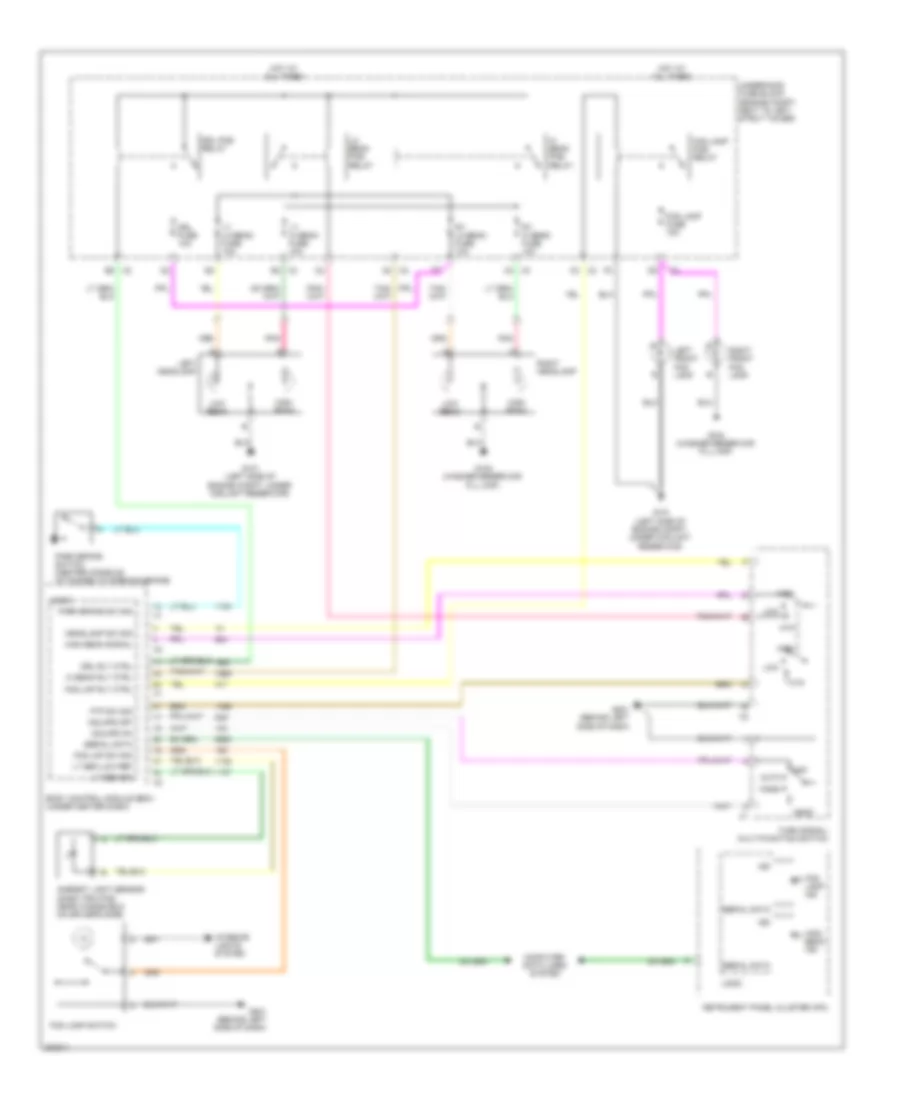
Headlights Wiring Diagram for Pontiac G5 2009
List of elements for Headlights Wiring Diagram for Pontiac G5 2009:
- Ambient light sensor (dash trim pad, near windshield on driver's side)
- Auto
- Body control module (bcm) (under center dash)
- Computer data lines system
- Drl fuse 10a
- Drl pcb relay
- Drl rly ctrl
- Fog lamp fuse 15a
- Fog lamp ind
- Fog lamp pcb relay
- Fog lamp switch
- Fog lmp rly ctrl
- Fog lmp sw sig
- Ftp
- Ftp sw sig
- G101 (left side of engine compt, under coolant reservoir)
- G102 (washer reservoir fill cap)
- G201 (behind left side of dash)
- Hdlmps off
- Hdlmps on
- Head
- Headlamp sw sig
- Hi beam pcb relay
- Hi beam rly ctrl
- High
- High beam
- High beam ind
- High beam signal
- Hot at all times
- Ign
- Instrument panel cluster (ipc)
- Interior lights system
- Left front fog lamp
- Left headlamp
- Lo beam pcb relay
- Logic
- Low
- Low beam
- Lt hi beam fuse 10a
- Lt lo beam fuse 10a
- Lt sen low ref
- Lt sen sig
- Off
- Park
- Park brake sw sig
- Park brake switch (center console, attached to parking brake)
- Pnk
- Right front fog lamp
- Right headlamp
- Rt hi beam fuse 10a
- Rt lo beam fuse 10a
- Serial data
- Turn signal/ multi-function switch
- Underhood fuse block (engine compt, next to left strut tower)
HORN
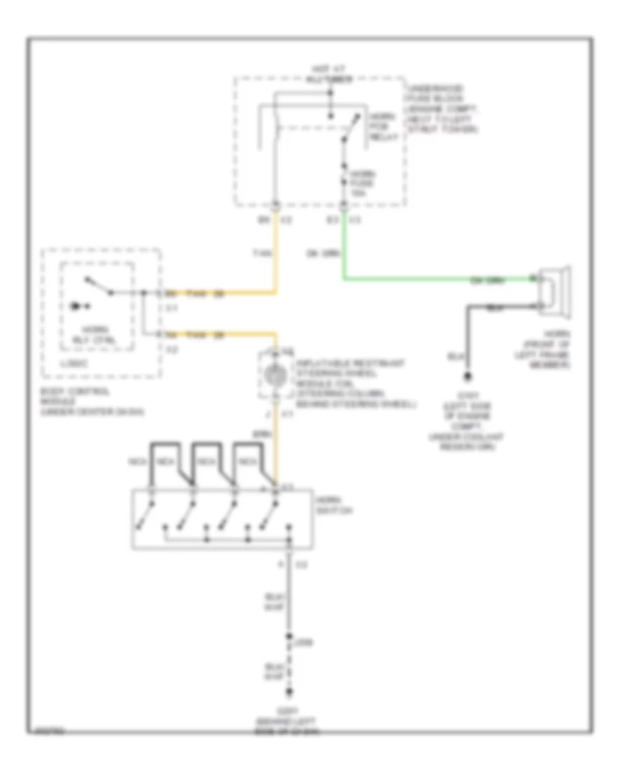
Horn Wiring Diagram for Pontiac G5 2009
List of elements for Horn Wiring Diagram for Pontiac G5 2009:
- B6 x2
- Body control module (under center dash)
- E3 x3
- G101 (left side of engine compt, under coolant reservoir)
- G201 (behind left side of dash)
- Horn (front of left frame member)
- Horn fuse 10a
- Horn pcb relay
- Horn rly ctrl
- Horn switch
- Hot at all times
- Inflatable restraint steering wheel module coil (steering column, behind steering wheel)
- J208
- Logic
- Nca
- Tan
- Underhood fuse block (engine compt, next to left strut tower)
INSTRUMENT CLUSTER
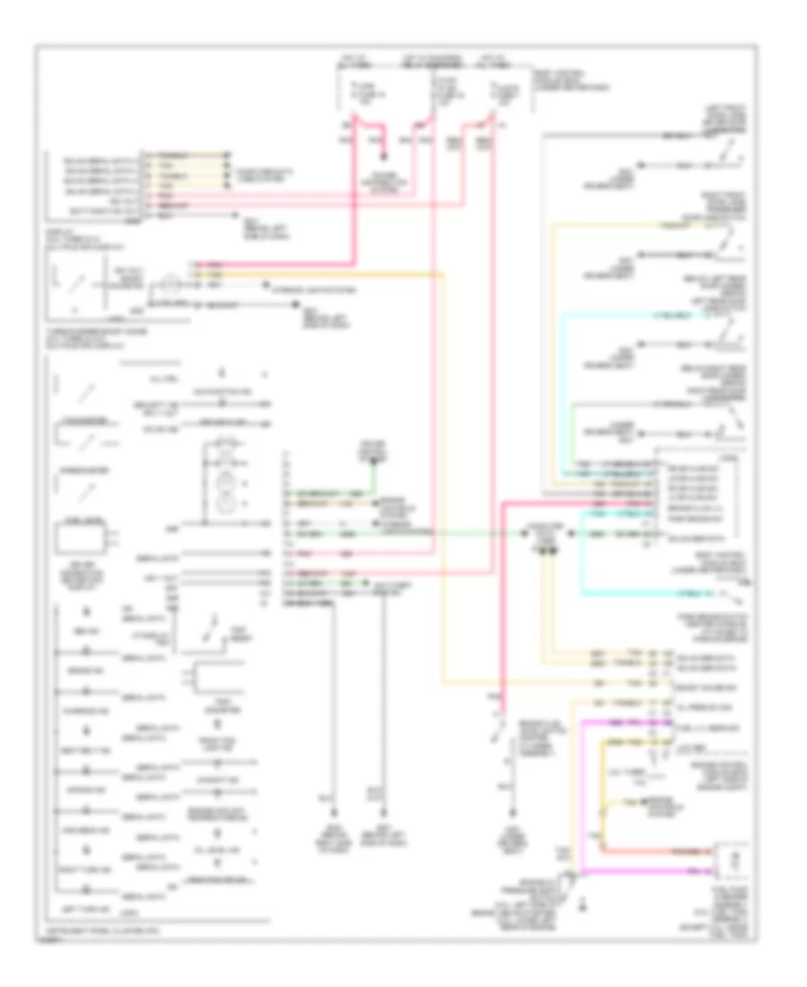
Instrument Cluster Wiring Diagram for Pontiac G5 2009
List of elements for Instrument Cluster Wiring Diagram for Pontiac G5 2009:
- (2 bulbs)
- (below left rear door hinges) (sedan) left rear door jamb switch
- (below right rear door hinges) (sedan) right rear door jamb switch
- (left front door jamb) driver door jamb switch
- (right front door jamb) passenger door jamb switch
- (under driver's seat) g301
- 2.0l turbo
- 2.2l
- Abs ind
- Air bag ind
- Anti-theft system
- Bat
- Batt positive volt
- Body control module (bcm) (under center dash)
- Boost gauge sig
- Brake fluid level switch (master cylinder assembly)
- Brake fluid lvl
- Brake ind
- Charging ind
- Clstr fuse 7 10a
- Computer data lines system
- Cruise control system
- Dic sw sig
- Display (2.0l turbo & w/ multiple info display)
- Driver information center (dic) display
- Engine control module (ecm) (left side of engine compt)
- Engine controls system
- Engine coolant temperature ind
- Engine oil pressure (eop) switch (2.0l: left side of engine, above starter) (2.2l: lower left rear of engine)
- Front fog lamp ind
- Fuel level
- Fuel lvl sens sig
- Fuel pump & sender assembly (2.0l: fuel tank assembly) (except 2.0l: inside fuel tank)
- G201 (behind left side of dash)
- G203 (behind right side of dash)
- G301 (under driver's seat)
- Gmlan ser data
- Gmlan ser data+
- Gmlan ser data-
- Gmlan serial data (+)
- Gmlan serial data (-)
- Gnd
- High beam ind
- Hot at all times
- Hot w/ run/crnk relay energized
- Hvac/ ip ign fuse 16 10a
- Ign
- Ign 1 volt
- Ign volt
- Ign volt boost gauge sig
- Instrument panel cluster (ipc)
- Interior lights system
- Left turn ind
- Lf dr ajar sw
- Logic
- Low ref
- Lr dr ajar sw
- Malfunction ind
- Mil ctrl
- Oil level ind
- Oil pres sw sig
- Park brake sw
- Park brake switch (center console, attached to parking brake)
- Pnk
- Power distribution system
- Rf dr ajar sw
- Right turn ind
- Rr dr ajar sw
- Seat belt ind
- Security ind
- Security ind sply volt
- Serial data
- Speedometer
- Tachometer
- Tan
- Traction off ind
- Trip reset
- Trip/ odometer
- Turbocharger boost gauge (2.0l turbo & w/o multiple info display)
- Up-shift ind
- Vf display trip
- Wpr fuse 15 10a
INTERIOR LIGHTS
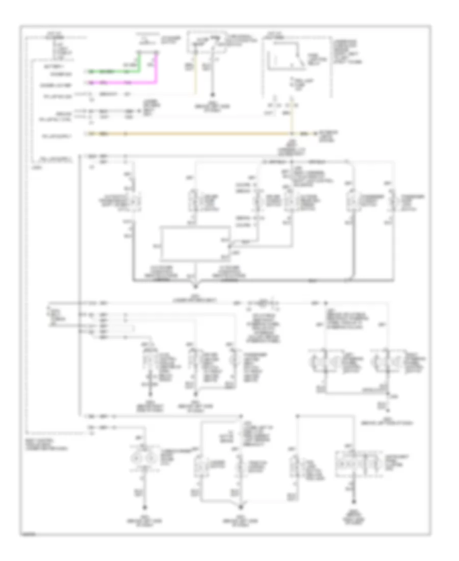
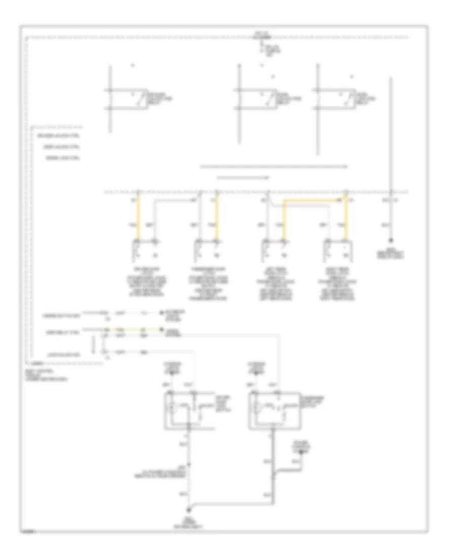
Courtesy Lamps Wiring Diagram for Pontiac G5 2009
List of elements for Courtesy Lamps Wiring Diagram for Pontiac G5 2009:
- "b" pillar)
- A10
- Battery+
- Body control module (bcm) (under center dash)
- Ctsy lp ctrl
- Dome lamp
- Door
- Driver door ajar switch (lower left "a" pillar between door hinges)
- Driver's seat)
- Front passenger door ajar switch (lower right "a" pillar between door hinges)
- G301 (under
- G401 (center of rear shelf, near left speaker)
- Ground
- Hot at all times
- Inside rearview mirror (isrvm)
- Int light fuse 27 10a
- J401
- Left rear door ajar switch (sedan) (center of left "b" pillar between hinges)
- Lf door ajar
- Logic
- Lr door ajar
- Off
- Rear compartment courtesy lamp
- Rear compartment courtesy lamp diode
- Rear compartment lid release actuator (latch assembly)
- Rear compt ajar
- Rf door ajar
- Right rear door ajar switch (sedan) (center of right "b" pillar between hinges)
- Rr door ajar
- W/ onstar
- W/o onstar
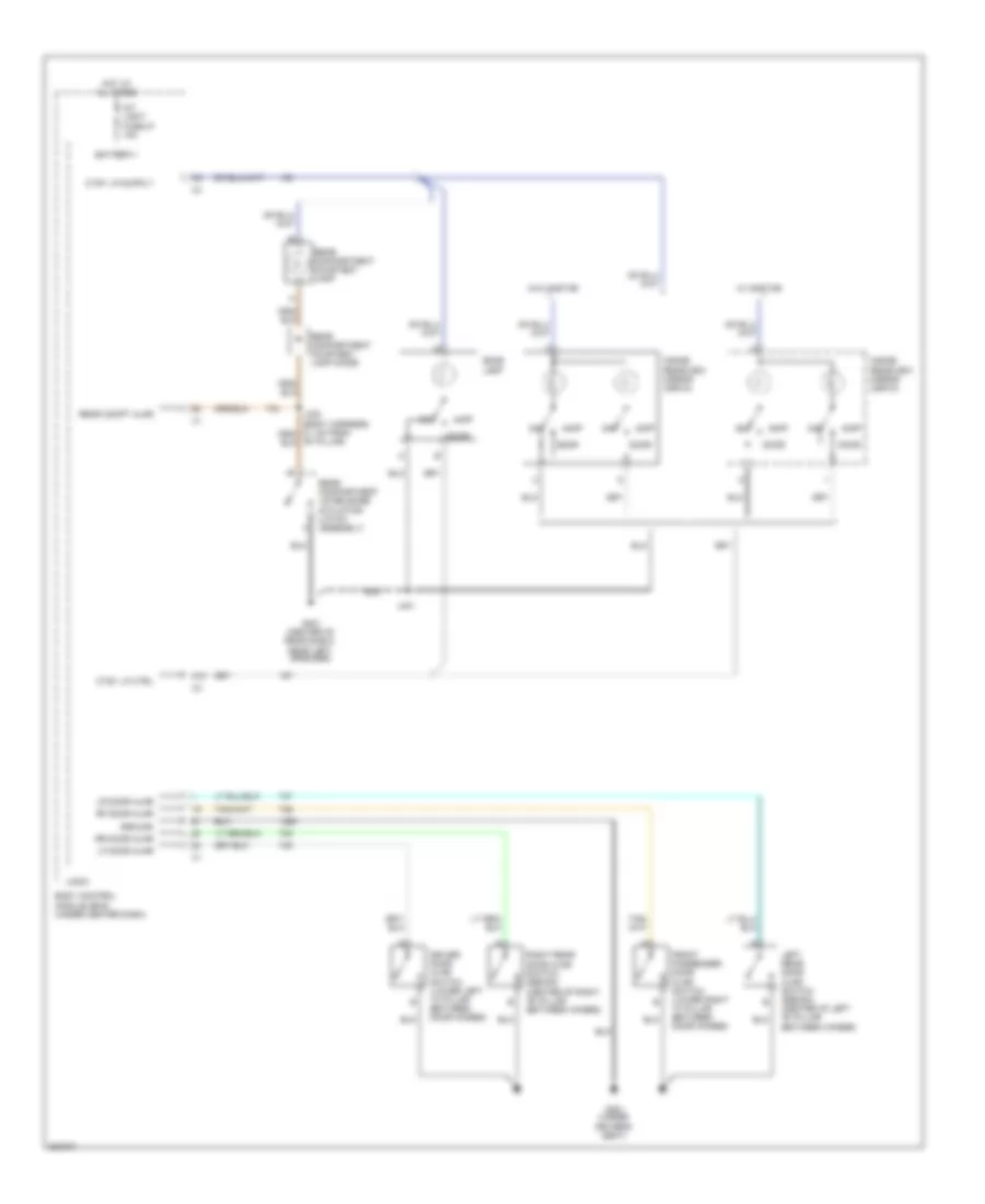
Instrument Illumination Wiring Diagram for Pontiac G5 2009
List of elements for Instrument Illumination Wiring Diagram for Pontiac G5 2009:
- (coupe)
- (sedan)
- (under driver's seat) g301
- Automatic transmission shift lever (a/t)
- B12
- Battery+
- Body control module (bcm) (under center dash)
- C11
- C12
- Dimmer low ref
- Dimmer sig
- Driver door lock switch
- Driver heated seat switch (w/ front heated seats)
- Driver window switch
- Exterior lights system
- F x1
- Fog lamp switch (deluxe fog lamp)
- G201 (behind left side of dash)
- G203 (behind right side of dash)
- G301 (under driver's seat)
- Ground
- Hazard switch
- Head
- Hot at all times
- Hvac control module (center of dash, below radio)
- I/p dimmer switch
- Inflatable restraint steering wheel module coil (steering column, behind steering wheel)
- Instrument panel cluster (ipc)
- Int light fuse 27 10a
- J208
- J233 (lower left of dash, 5 cm from ambient light sensor breakout)
- J361 (body harness, 3.75 cm from g301)
- J500
- Left steering wheel control switch
- Logic
- Off
- Outside rearview mirror switch
- Park auto
- Park lamp pcb relay
- Passenger door lock switch
- Passenger heated seat switch (w/ front heated seats)
- Passenger window switch
- Pk lmp rly ctrl
- Pk lmp sw sig
- Prk lamp fuse 10a
- Right steering wheel control switch
- Swc bklt fuse 28 2a
- Traction control switch
- Turbocharger boost gauge (2.0l)
- Turn signal/ multi-function switch
- Underhood fuse block (engine compt, next to left strut tower)
- W/ active brake
- W/ power windows & remote outside mirrors
- W/o power windows & remote outside mirrors
- X2 a2
- X2 b
- X2 b7
- X3 b
- X5 d1
POWER DISTRIBUTION
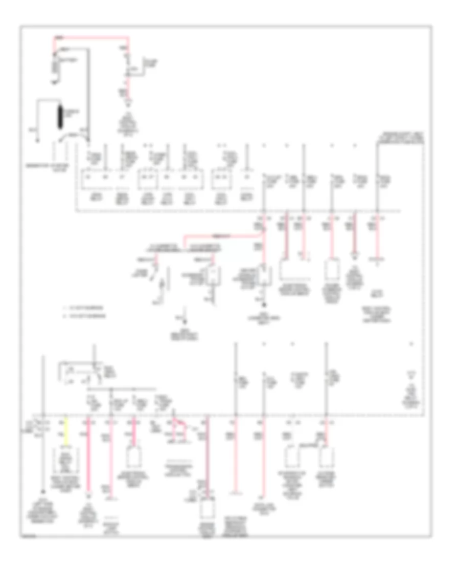
Power Distribution Wiring Diagram (1 of 3) for Pontiac G5 2009
List of elements for Power Distribution Wiring Diagram (1 of 3) for Pontiac G5 2009:
- (engine compt, next to left strut tower) underhood fuse block
- 2.2l 2.0l turbo
- 50a
- A/t
- Abs 2 fuse 10a
- Abs 3 fuse 20a
- Abs fuse 40a
- Backup lamp switch
- Battery
- Bck up fuse 10a
- Bcm2 fuse 40a
- Bcm3 fuse 30a
- Body control module (bcm) (under center dash)
- Center console accessory power outlet
- Chmsl relay
- Cigar lighter
- Cnstr vent fuse 10a
- Cool fan 1 fuse 30a
- Cool fan 1 relay
- Cool fan 2 fuse 30a
- Cool fan 2 relay
- Crnk fuse 30a
- Crnk relay
- D10 x3
- Data link connector (dlc)
- Dlc fuse 15a
- E6 (not used)
- Ecm/ trans fuse 15a
- Electronic brake control module (ebcm)
- Engine control module (ecm)
- Eps fuse 60a
- Evaporative emission (evap) canister vent solenoid valve
- Fusible link
- G101 (left side of engine compartment, under coolant reservoir)
- G203 (behind right side of dash)
- G301 (under driver's seat)
- Generator
- Hvac relay
- I/p accessory power outlet
- If equipped
- Inflatable restraint sensing & diagnostic module (sdm)
- Inline fuse
- Ip ign fuse 20a
- Mir/ ugdo fuse 5a
- Outlet fuse 20a
- Outside rearview mirror switch
- Pnk
- Power steering control module (pscm)
- Rear defog fuse 40a
- Rear defog relay
- Red
- Run/ crank relay coil ctrl
- Run/ crnk relay
- Sdm fuse 10a
- Starter motor
- To body control module (diagram 2 of 3)
- To body control module (diagram 3 of 3)
- To pwr/ trn relay (diagram 2 of 3)
- Transmission control module (tcm)
- W/ active brake
- W/ cigarette lighter ashtray
- W/o active brake
- W/o cigarette lighter ashtray
- Wiper fuse 25a
- Wpr hi/lo relay
- Wpr on/off relay
- X1 f5
- X3 b2
- X3 c5
- X3 f2
- X4 b1
- X4 c2
- X5 a2
- X5 a5
- X5 b2
- X5 d5
- X5 e5
- X6 a
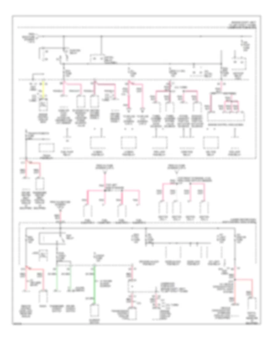
Power Distribution Wiring Diagram (2 of 3) for Pontiac G5 2009
List of elements for Power Distribution Wiring Diagram (2 of 3) for Pontiac G5 2009:
- (coupe) (sedan)
- (engine compt, next to left strut tower) underhood fuse block
- (if equipped)
- (not used)
- (top front of engine, 10 cm from mass air flow sensor) j141
- (top left pnk
- (under center dash) body control module (bcm)
- 2.0l turbo
- 2.2l
- 2.2l 2.0l turbo
- A/c cltch relay
- A2 x1
- Air pump fuse 40a
- Air pump relay (2.2l)
- Air sol relay (2.2l/pzev)
- C11
- D1 x3
- D10
- Digital radio receiver (if equipped)
- Door lock pcb relay
- Door unlock pcb relay
- Dr door unlock pcb relay
- Dr lck fuse 15a
- Driver heated seat control module (if equipped)
- Driver window switch
- Drl pcb relay
- E x2
- E10 (not used)
- E3 x5
- E4 x5
- Ecm/ tcm fuse 10a
- Eng vlv sol fuse 10a
- Engine control module (ecm)
- Evaporative emission (evap) canister purge solenoid valve
- Exh fuse 10a
- Exhaust camshaft position actuator solenoid
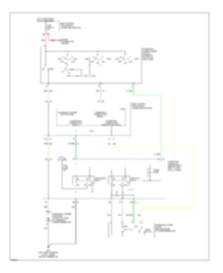
- Fog lamp pcb relay
- From bcm3 fuse c (diagram 1 of 3)
- From inj fuse (diagram 2 of 3)
- From inline fuse (diagram 1 of 3)
- Fuel injector 1
- Fuel injector 2
- Fuel injector 3
- Fuel injector 4
- Fuel pump relay
- Heated oxygen sensor (ho2s) 1
- Heated oxygen sensor (ho2s) 2
- Hi beam pcb relay
- Horn pcb relay
- Ignition coil 1
- Ignition coil 2
- Ignition coil 3
- Ignition coil 4
- Inj fuse 15a
- Int light fuse 10a
- Int light pcb relay
- Intake camshaft position actuator solenoid
- J113
- J210 (w/ vehicle communication & digital audio system)
- Lo beam pcb relay
- Logic
- M/t
- Mass air flow (maf)/ intake air temperature (iat) sensor
- Passenger heated seat control module
- Passenger window switch
- Pcm/ ecm fuse 15a
- Pnk
- Prk lamp pcb relay
- Pwr wndw fuse 30a
- Pwr/trn relay
- Radio
- Rap relay
- Rdo fuse 15a
- Remote control door lock receiver (rcdlr)
- Rly ctrl
- S roof fuse 15a
- Side of engine) j103
- Sunroof switch
- To splice j103 (diagram 2 of 3)
- To splice j141 (diagram 2 of 3)
- Transmission control module (tcm)
- Trunk pcb relay
- Trunk/htd seats fuse 20a
- Turbo charger bypass valve solenoid
- Turbo charger waste gate solenoid
- Underhood fuse block (engine compt, next to left strut tower)
- Vehicle communication interface module (vcim) (if equipped)
- W/ keyless entry
- W/ power sliding sunroof
- X1 f6
- X3 d4
- X5 b1
- X5 e2
- Xm/ onstar fuse 10a
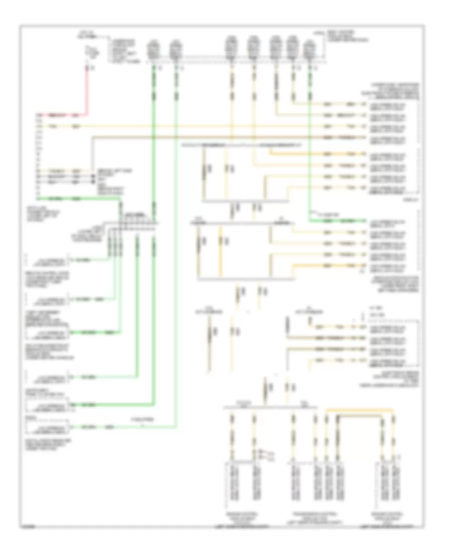
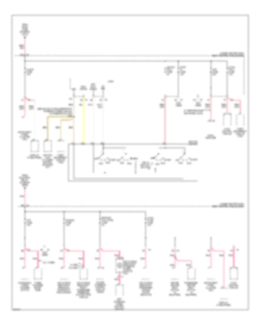
Power Distribution Wiring Diagram (3 of 3) for Pontiac G5 2009
List of elements for Power Distribution Wiring Diagram (3 of 3) for Pontiac G5 2009:
- (behind inflatable restraint steering wheel module, in steering column) j206
- (not used)
- (under center dash) body control module (bcm)
- 2.0l turbo
- 5v ref
- A4 x2
- A8 x3
- Acc
- Air bag fuse 10a
- Amp fuse 20a
- Audio amplifier
- Clstr fuse 10a
- D11
- D12 x3
- Display (if equipped)
- Driver heated seat switch (if equipped)
- Eps/str whl cntrl fuse 2a
- From bcm2 fuse (diagram 1 of 3)
- From run/crnk relay (diagram 1 of 3)
- Hvac control module
- Hvac/ ip ign fuse 10a
- Hvac/ pk3 + fuse 10a
- Ign sw/ pk3 + fuse 2a
- Ignition lock cylinder control solenoid (a/t)
- Ignition switch
- Inflatable restraint front passenger presence system (pps) module
- Inflatable restraint passenger air bag on/off indicator
- Inflatable restraint sensing & diagnostic module (sdm)
- Inflatable restraint steering wheel module coil
- Instrument panel cluster (ipc)
- Key-in ignition switch
- Left steering wheel control switch
- Logic
- Off
- Off/ run/ crank
- Passenger heated seat switch (if equipped)
- Pnk
- Pnk c
- Pnk d
- Power steering control module (pscm)
- Run
- Run/ crank
- Start
- Stop lp fuse 10a
- Theft deterrent module (tdm)
- Turbo changer boost gage
- W/ performance enhanced audio
- W/ srs
- W/o srs
- Windshield wiper/ washer switch
- Wip fuse 10a
- X1 c pnk
- X2 a1
- X3 d6
- X4 d3
POWER DOOR LOCKS
Power Door Locks Wiring Diagram (1 of 2) for Pontiac G5 2009
List of elements for Power Door Locks Wiring Diagram (1 of 2) for Pontiac G5 2009:
- 2.2l
- B10
- Batt + volt
- Body control module (under center dash)
- Clstr fuse 7 10a
- Computer data lines system
- D10
- D8 x2
- Driver door jamb switch (left front door jamb)
- Enable sig
- G201 (behind left side of dash)
- G301 (under driver's seat)
- G401 (center of rear shelf, near left speaker)
- Gmlan
- Gmlan low speed
- Gmlan serial data +
- Gmlan serial data -
- Gnd
- Ground
- Hot at all times
- Instrument panel cluster (ipc)
- Interior lights system
- J330 (body harness, 5.1 cm from "b" pillar)
- Jx200 (lower left of dash, below hood release)
- Keyless entry antenna
- Left rear door jamb switch (sedan) (below left rear door hinges)
- Lf door jamb
- Lid release sw sig
- Logic
- Lr door jamb
- Nca
- Power distribution system
- Rdo fuse 23 15a
- Rear compartment lid release actuator (latch assembly)
- Rear compartment lid release switch
- Rear compt ajar
- Release actuator
- Remote control door lock receiver (w/ keyless entry) (under right dash trim panel)
- Rf door jamb
- Right front door jamb switch (right front door jamb)
- Right rear door jamb switch (sedan) (below right rear door hinges)
- Rr door jamb
- Tan
- Trunk pcb relay
- Trunk/ htd seats fuse 20a
- Underhood fuse block (engine compt, next to left strut tower)
- Xm/ onstar fuse 24 10a
Power Door Locks Wiring Diagram (2 of 2) for Pontiac G5 2009
List of elements for Power Door Locks Wiring Diagram (2 of 2) for Pontiac G5 2009:
- Body control module (under center dash)
- Door lock pcb relay
- Door unlock ctrl
- Door unlock pcb relay
- Doors lock ctrl
- Dr door unlock ctrl
- Dr door unlock pcb relay
- Dr lck fuse 26 15a
- Driver door latch (power door locks w/ remote keyless entry & onstar) (center rear of driver's door)
- Driver door lock switch
- Driver's seat)
- E12 x4
- Exterior lights system
- G203 (behind right side of dash)
- G301 (under
- Hazard switch sig
- Horn relay ctrl
- Horns system
- Hot at all times
- Interior lights system
- J500 (w/ power windows & remote outside mirrors)
- Left rear door latch (sedan & power door locks w/ remote keyless entry) (center rear of left rear door)
- Lock
- Lock/unlock sig
- Logic
- Passenger door latch (power door locks w/ remote keyless entry) (center rear of front passenger's door)
- Passenger door lock switch
- Power windows system
- Right rear door latch (sedan & power door locks w/ remote keyless entry) (center rear of right rear door)
- Tan
- Unlock
POWER MIRRORS
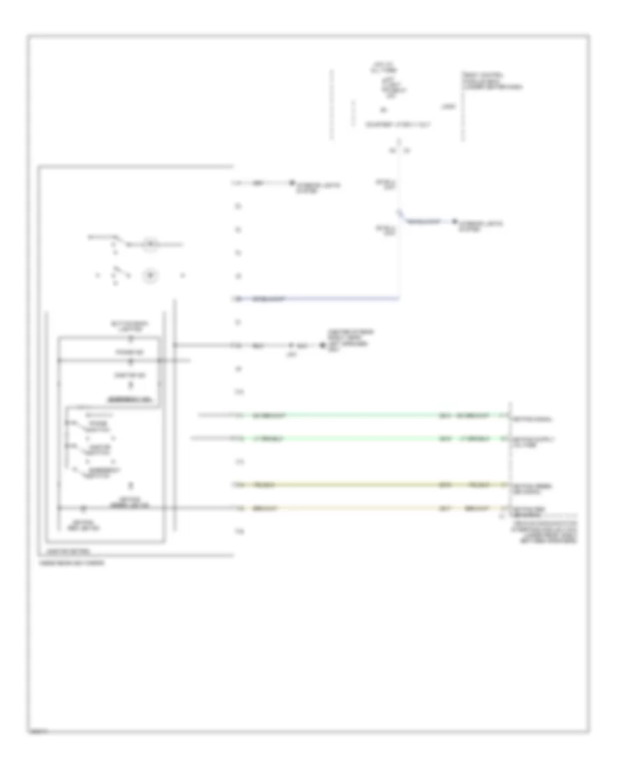
Automatic Day/Night Mirror Wiring Diagram, with OnStar for Pontiac G5 2009
List of elements for Automatic Day/Night Mirror Wiring Diagram, with OnStar for Pontiac G5 2009:
- (center of rear shelf, near left speaker) g401
- Body control module (bcm) (under center dash)
- Button back lighting
- Courtesy lp sply volt
- Emergency ind
- Emergency switch
- Hot at all times
- Inside rearview mirror
- Int light fuse 27 10a
- Interior lights system
- J401
- Keypad green led ind
- Keypad green led signal
- Keypad red led ind
- Keypad red led signal
- Keypad signal
- Logic
- Onstar ind
- Onstar keypad
- Onstar switch
- Phone ind
- Phone switch
- Vehicle communication interface module (vcim) (under rear, shelf between speakers)
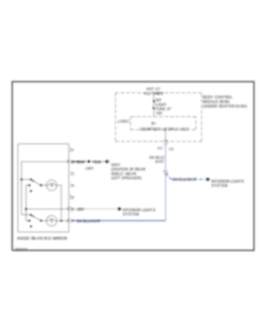
Automatic Day/Night Mirror Wiring Diagram, without OnStar for Pontiac G5 2009
List of elements for Automatic Day/Night Mirror Wiring Diagram, without OnStar for Pontiac G5 2009:
- Body control module (bcm) (under center dash)
- Courtesy lp sply volt
- G401 (center of rear shelf, near left speaker)
- Hot at all times
- Inside rearview mirror
- Int light fuse 27 10a
- Interior lights system
- J401
- Logic
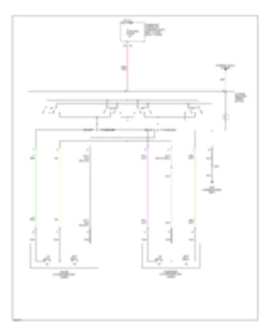
Power Mirrors Wiring Diagram for Pontiac G5 2009
List of elements for Power Mirrors Wiring Diagram for Pontiac G5 2009:
- Down
- Driver
- Driver outside rearview mirror
- G301 (under driver's seat)
- Hot at all times
- Interior lights system
- J500
- Left
- Left/ right
- Mir/ugdo fuse 5a
- Nca
- Outside rearview mirror switch
- Passenger
- Passenger outside rearview mirror
- Right
- Underhood fuse block (in engine compt, next to left strut tower)
- Up/ down
POWER SEATS
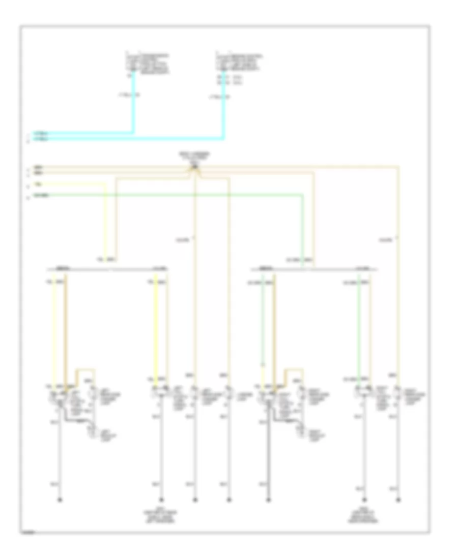
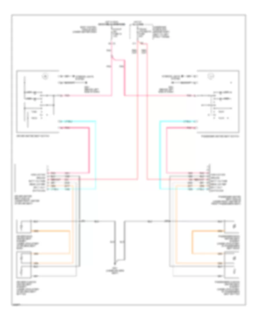
Heated Seats Wiring Diagram for Pontiac G5 2009
List of elements for Heated Seats Wiring Diagram for Pontiac G5 2009:
- (under driver's seat)
- A8 x3
- Batt voltage
- Body control module (bcm) (under center dash)
- C11
- Driver heated seat module (under front center of driver seat)
- Driver heated seat switch
- Driver's back heated seat element (under upholstery of driver's seat back)
- Driver's cushion heated seat element (under upholstery of driver's seat bottom)
- G201 (behind left side of dash)
- G301
- Ground
- High
- High/low sig
- Hot at all times
- Hot w/ run/ crank relay energized
- Hvac/ip ign fuse 16 10a
- Interior lights system
- J301
- J302
- Low
- Passenger heated seat module (under front center of front passenger's seat)
- Passenger heated seat switch
- Passenger's back heated seat element (under upholstery of passenger's seat back)
- Passenger's cushion heated seat element (under upholstery of passenger's seat bottom)
- Pnk
- Sens low ref
- Sply volt
- Switch sig
- Trunk/ htd seats fuse 20a
- Underhood fuse block (engine compt, next to left strut tower)
POWER TOP/SUNROOF
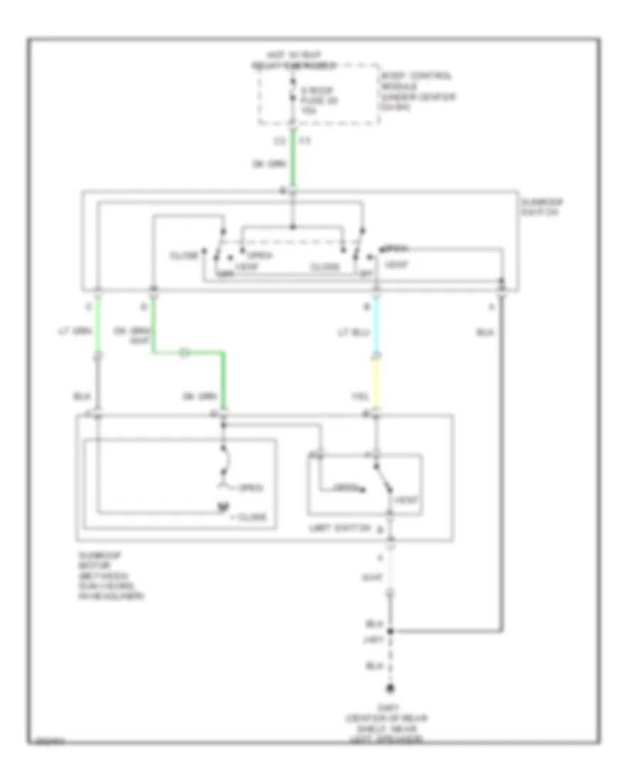
Power Top/Sunroof Wiring Diagram for Pontiac G5 2009
List of elements for Power Top/Sunroof Wiring Diagram for Pontiac G5 2009:
- + close
- + open
- Body control module (under center dash)
- Close
- G401 (center of rear shelf, near left speaker)
- Hot w/ rap relay energized
- J401
- Limit switch
- Off
- Open
- S roof fuse 20 15a
- Sunroof motor (between sun visors, in headliner)
- Sunroof switch
- Vent
- Vent off
POWER WINDOWS
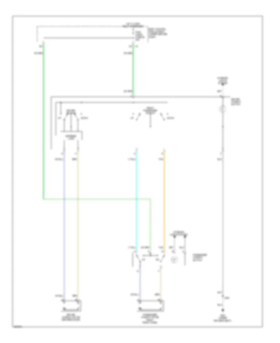
Power Windows Wiring Diagram, Coupe for Pontiac G5 2009
List of elements for Power Windows Wiring Diagram, Coupe for Pontiac G5 2009:
- Body control module (bcm) (under center dash)
- Down
- Driver switch
- Driver window motor (driver's door)
- Driver window switch
- Express logic
- Front passenger switch
- G301 (under driver's seat)
- Hot w/ rap relay energized
- Interior lights system
- J500
- Passenger window motor (right front door)
- Passenger window switch
- Pwr wndw fuse 29 30a
- Tan
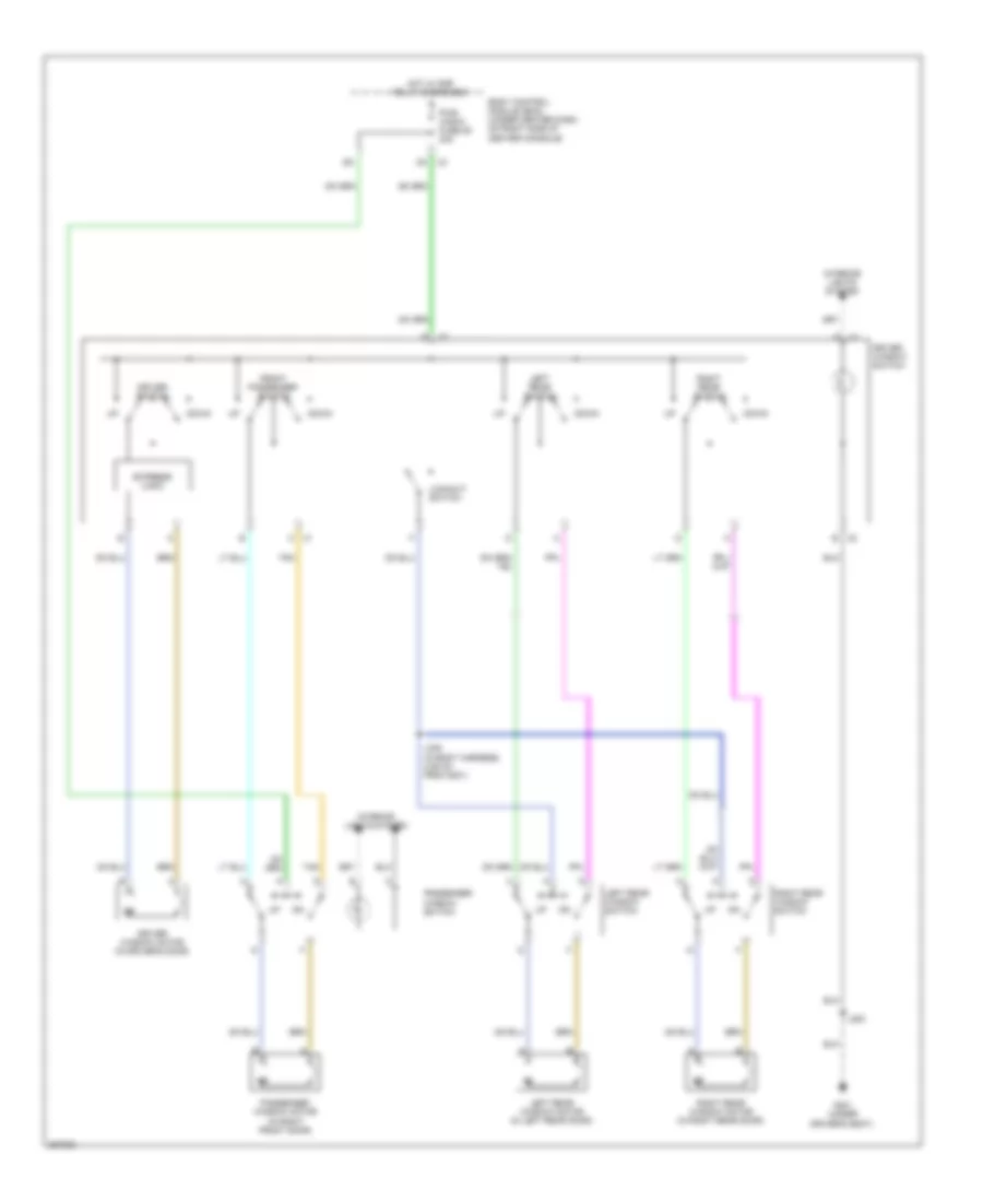
Power Windows Wiring Diagram, Sedan for Pontiac G5 2009
List of elements for Power Windows Wiring Diagram, Sedan for Pontiac G5 2009:
- Body control module (bcm) (under center dash, on right side of center console)
- Down
- Driver switch
- Driver window motor (in driver's door)
- Driver window switch
- Express logic
- Front passenger switch
- G301 (under driver's seat)
- Hot w/ rap relay energized
- Interior lights system
- J200
- J335 (in body harness, 2.55 cm from g301)
- Left rear switch
- Left rear window motor (in left rear door)
- Left rear window switch
- Lockout switch
- Passenger window motor (in right front door)
- Passenger window switch
- Pwr wndw fuse 29 30a
- Right rear switch
- Right rear window motor (in right rear door)
- Right rear window switch
- Tan
- X1 c
- X2 b
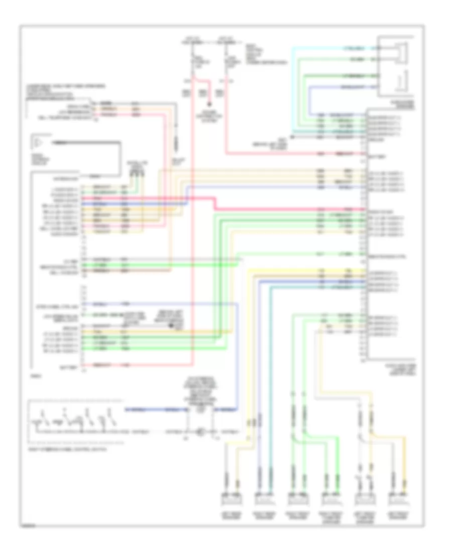
RADIO
Radio Wiring Diagram, with Amplifier for Pontiac G5 2009
List of elements for Radio Wiring Diagram, with Amplifier for Pontiac G5 2009:
- (behind left side of dash, near steering column) g201
- (on steering column, behind steering wheel) inflatable restraint steering wheel module coil
- (under rear, shelf between speakers) (if equipped) vehicle communication interface module (vcim)
- 10v ref
- Amp fuse 6 20a
- Antenna sig
- Audio amplifier (under left side of dash)
- Audio common
- Bare
- Battery
- Body control module (bcm) (under center dash)
- Cell telephone voice sig
- Cell voice low ref
- Cell voice sig
- Coax
- Computer data lines system
- D10
- Drain wire
- G201 (behind left side of dash)
- Ground
- Hot at all times
- L audio sig (+)
- Left front speaker
- Left front tweeter speaker
- Left rear speaker
- Lf lo lev audio (+)
- Lf lo lev audio (-)
- Lf spkr out (+)
- Lf spkr out (-)
- Low reference
- Low speed gmlan serial data
- Lr lo lev audio (+)
- Lr lo lev audio (-)
- Lr spkr out (+)
- Lr spkr out (-)
- Mute
- Nca
- Pnk
- Power distribution system
- R audio sig (+)
- Radio
- Radio antenna module
- Radio on sig
- Rdo fuse 23 15a
- Remote radio ctrl
- Rf lo lev audio (+)
- Rf lo lev audio (-)
- Rf spkr out (+)
- Rf spkr out (-)
- Right front speaker
- Right front tweeter speaker
- Right rear speaker
- Right steering wheel control switch
- Rr lo lev audio (+)
- Rr lo lev audio (-)
- Rr spkr out (+)
- Rr spkr out (-)
- Satellite radio circuit
- Srce
- Strg wheel ctrl sig
- Sub spkr out (+)
- Sub spkr out (-)
- Subwoofer speaker
- Tan
- Tan b
- Vol down
- Vol up
- X4 a1
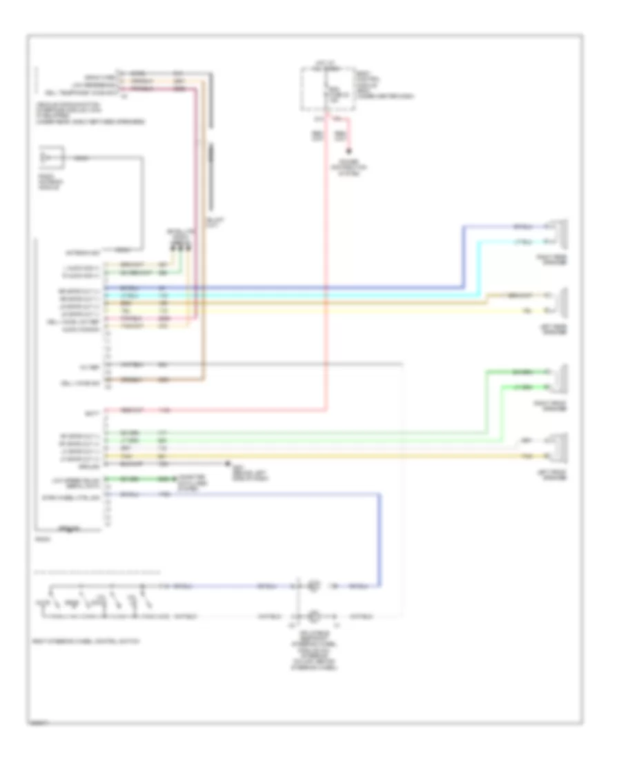
Radio Wiring Diagram, without Amplifier for Pontiac G5 2009
List of elements for Radio Wiring Diagram, without Amplifier for Pontiac G5 2009:
- 10v ref
- Antenna sig
- Audio common
- Bare
- Batt
- Body control module (bcm) (under center dash)
- Cell telephone voice sig
- Cell voice low ref
- Cell voice sig
- Coax
- Computer data lines system
- D10
- Drain wire
- G201 (behind left side of dash)
- Ground
- Hot at all times
- Inflatable restraint steering wheel module coil (steering column, behind steering wheel)
- L audio sig (+)
- Left front speaker
- Left rear speaker
- Lf spkr out (+)
- Lf spkr out (-)
- Low reference
- Low speed gmlan serial data
- Lr spkr out (+)
- Lr spkr out (-)
- Mute
- Power distribution system
- R audio sig (+)
- Radio
- Radio antenna module
- Rdo fuse 23 15a
- Rf spkr out (+)
- Rf spkr out (-)
- Right front speaker
- Right rear speaker
- Right steering wheel control switch
- Rr spkr out (+)
- Rr spkr out (-)
- Satellite radio circuit
- Srce
- Strg wheel ctrl sig
- Tan
- Vehicle communication interface module (vcim) (if equipped) (under rear, shelf between speakers)
- Vol down
- Vol up
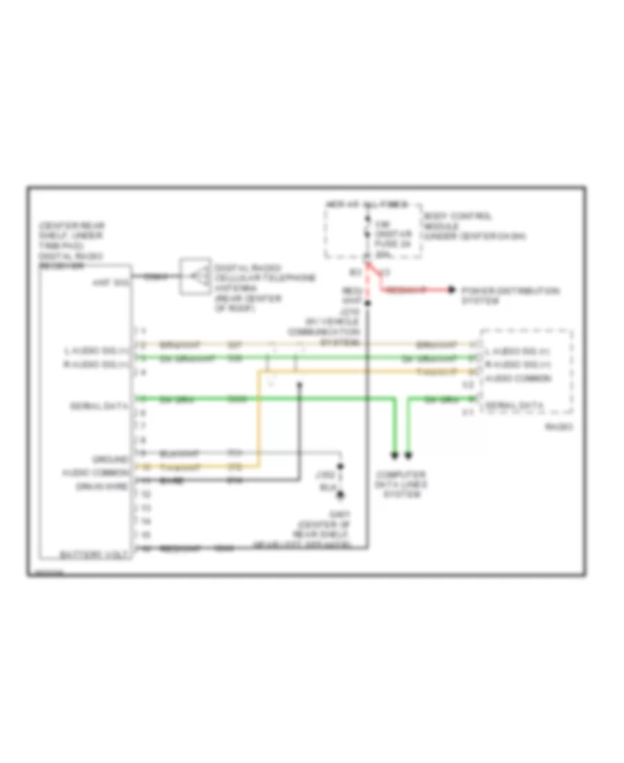
Satellite Radio Wiring Diagram for Pontiac G5 2009
List of elements for Satellite Radio Wiring Diagram for Pontiac G5 2009:
- (center rear shelf, under trim pad) digital radio receiver
- Ant sig
- Audio common
- Bare
- Battery volt
- Body control module (under center dash)
- Coax
- Computer data lines system
- Digital radio/ cellular telephone antenna (rear center of roof)
- Drain wire
- G401 (center of rear shelf, near left speaker)
- Ground
- Hot at all times
- J210 (w/ vehicle communication system)
- J352
- L audio sig (+)
- Power distribution system
- R audio sig (+)
- Radio
- Serial data
- Xm/ onstar fuse 24 10a
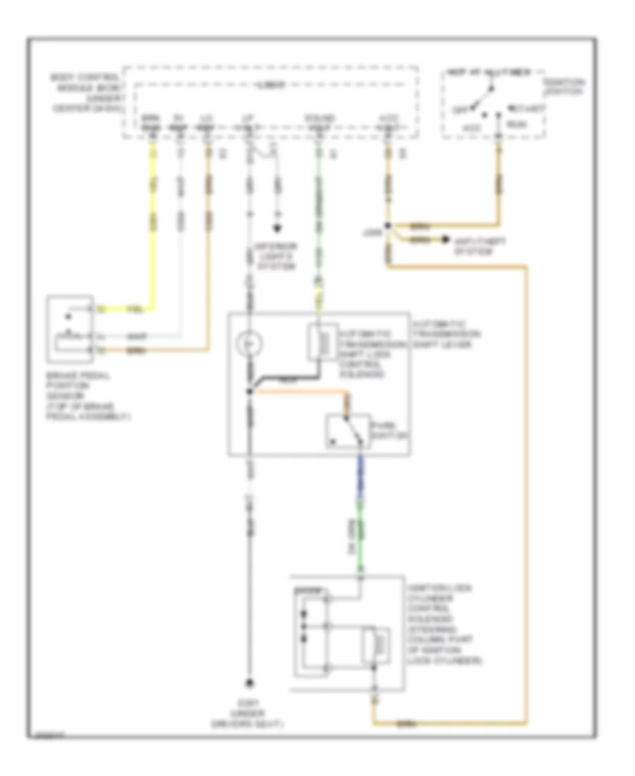
SHIFT INTERLOCK
Shift Interlock Wiring Diagram for Pontiac G5 2009
List of elements for Shift Interlock Wiring Diagram for Pontiac G5 2009:
- 5v ref
- Acc
- Acc volt
- Anti-theft system
- Automatic transmission shift lever
- Automatic transmission shift lock control solenoid
- B12
- Body control module (bcm) (under center dash)
- Brake pedal position sensor (top of brake pedal assembly)
- Brk sns
- Diode
- G301 (under driver's seat)
- Hot at all times
- Ignition lock cylinder control solenoid (steering column, part of ignition lock cylinder)
- Ignition switch
- Interior lights system
- J206
- Lo ref
- Logic
- Lp volt
- Nca
- Off
- Park switch
- Run
- Solnd volt
- Start
STARTING/CHARGING
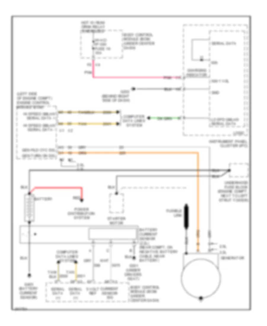
Charging Wiring Diagram for Pontiac G5 2009
List of elements for Charging Wiring Diagram for Pontiac G5 2009:
- (left side of engine compt) engine control module (ecm)
- 2.0l
- 2.0l 2.2l
- 2.2l
- 5 volt ref
- Battery
- Body control module (bcm) (under center dash)
- Charging indicator
- Computer data lines system
- Current sensor sig
- F6 x4
- Fusible link
- G203 (behind right side of dash)
- G301 (under driver's seat)
- G403 (battery current sensor)
- Gen fild cyc sig
- Gen turn on sig
- Generator
- Gnd
- Hi speed gmlan serial data +
- Hi speed gmlan serial data - x1
- Hot w/ run/ crnk relay energized
- Hvac/ ip ign fuse 16 10a
- Ign
- Ign 1 vol
- Instrument panel cluster (ipc)
- Lo spd gmlan serial data
- Logic
- Pnk
- Power distribution system
- Red
- Serial data
- Serial data (+)
- Starter motor
- Tan
- Underhood fuse block (engine compt, next to left strut tower)
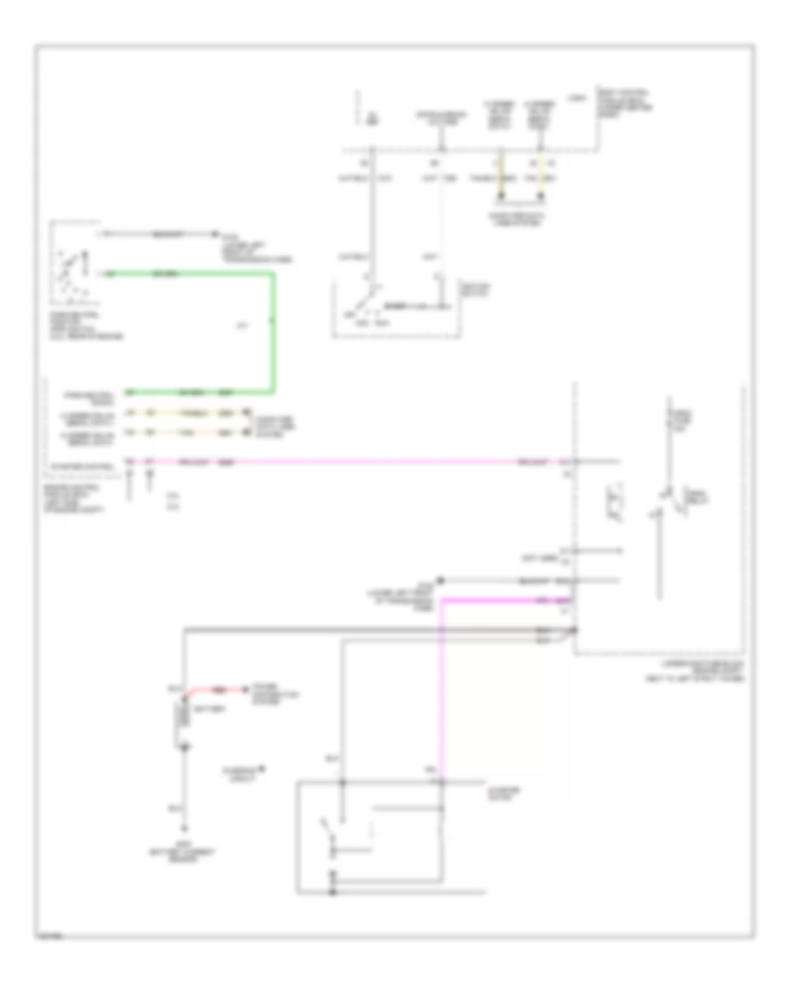
Starting Wiring Diagram for Pontiac G5 2009
List of elements for Starting Wiring Diagram for Pontiac G5 2009:
- (not used)
- 2.0l
- 2.2l
- 5v ref
- A/t
- Acc
- B10
- B12
- Battery
- Body control module (bcm) (under center dash)
- Charging circuit
- Computer data lines system
- Crnk fuse 30a
- Crnk relay
- Engine control module (ecm) (left side of engine compt)
- G105 (lower left front of transmission case)
- G403 (battery current sensor)
- Hi speed gmlan serial data +
- Hi speed gmlan serial data -
- Ignition switch
- Logic
- N d
- Off
- Off/run/crank voltage
- Park/neutral position (pnp) switch (2.2l: rear of engine)
- Park/neutral signal
- Power distribution system
- Red
- Run
- Start
- Starter control
- Starter motor
- Tan
- Underhood fuse block (engine compt, next to left strut tower)
SUPPLEMENTAL RESTRAINTS
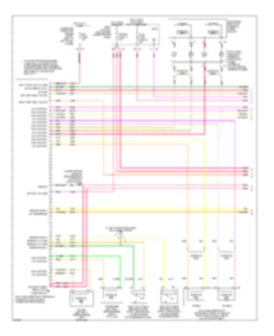
Supplemental Restraints Wiring Diagram (1 of 2) for Pontiac G5 2009
List of elements for Supplemental Restraints Wiring Diagram (1 of 2) for Pontiac G5 2009:
- (lower corner of passenger's door)
- (under center console, near sensing & diagnostic module (sdm)) g306
- A pnk
- Air bag fuse 13 10a
- B tan
- Batt positive voltage
- Body control module (bcm) (under center dash)
- Case ground
- Driver seat belt pretensioner (left "b" pillar)
- Gmlan serial data
- Ground
- High control
- Hot at all times
- Hot in run or start
- Hot w/ run/ run/ crnk relay energized
- Hvac/ ip ign fuse 16 10a
- Ignition voltage
- Ind
- Inflatable restraint instrument panel (ip) module (right side of dash, above glove compartment)
- Inflatable restraint sensing & diagnostic module (sdm) (under center console)
- Inflatable restraint steering module coil wheel (steering column, behind steering wheel)
- Inflatable restraint steering wheel module
- Left inflatable restraint side impact sensor (sis) (lower corner of driver's door)
- Left seat belt sw sig
- Logic
- Low control
- Low ref
- Low reference
- Occupant sens serial data
- Passenger seat belt pretensioner (right "b" pillar)
- Pin shorting bars engaged
- Pnk
- Right inflatable restraint side impact sensor (sis)
- Right seat belt sw sig
- Sdm fuse 10a
- Sensor signal
- Sensor voltage
- Shorting bar
- Stage 1
- Stage 2
- Tan
- Underhood fuse block (engine compt, next to left strut tower)
- W/ left & right roof side inflatable system
- When module connector is disconnected from harness: (shorting bars are connected between following pins: 8-9 & 10-11)
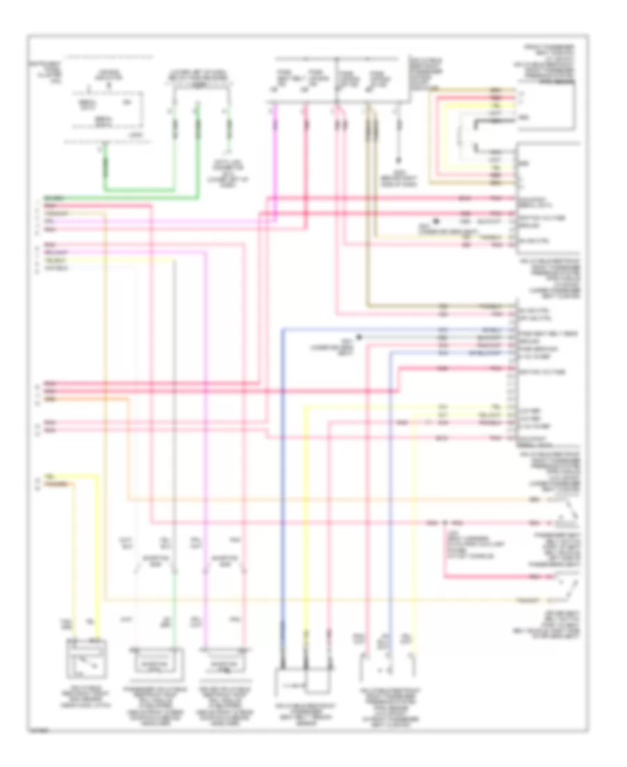
Supplemental Restraints Wiring Diagram (2 of 2) for Pontiac G5 2009
List of elements for Supplemental Restraints Wiring Diagram (2 of 2) for Pontiac G5 2009:
- (+)
- (-)
- (front passenger seat cushion) (w/ infant) inflatable restraint front passenger presence system (pps) sensor
- (lower left of dash, below hood release) jx200
- 5 volts ref
- Air bag indicator
- Data link connector (dlc) (lower left of dash)
- Driver inflatable restraint roof rail module (if equipped) (above front & rear door rails behind headliner)
- Driver seat belt switch (part of seat belt buckle, right side of driver's seat)
- G203 (behind right side of dash)
- G301 (under driver's seat)
- Grd
- Ground
- Ign
- Ignition voltage
- Inflatable restraint front end sensor (near hood latch)
- Inflatable restraint front passenger presence system (pps) module (w/infant) (under passenger seat cushion)
- Inflatable restraint front passenger presence system (pps) module (w/o infant) (under passenger seat cushion)
- Inflatable restraint front passenger presence system (pps) sensor (w/o infant) (in front passenger seat cushion)
- Inflatable restraint passenger air bag on/off indicator
- Inflatable restraint passenger seat belt tension sensor
- Instrument panel cluster (ipc)
- J337 (body harness, 6.5 cm from auxiliary power outlet console)
- Logic
- Low ref
- Nca
- Occupant serial data
- Off ind ctrl
- On ind ctrl
- Pass air bag ind
- Pass air bag off ind
- Pass air bag on ind
- Pass seat belt ind
- Pass seat belt sens
- Pass sens sig
- Passenger inflatable restraint roof rail module (if equipped) (above front & rear door rails behind headliner)
- Passenger seat belt switch (part of seat belt buckle, left side of passenger's seat)
- Pnk
- Pnk a
- Red
- Serial data
- Shorting bar
TRANSMISSION
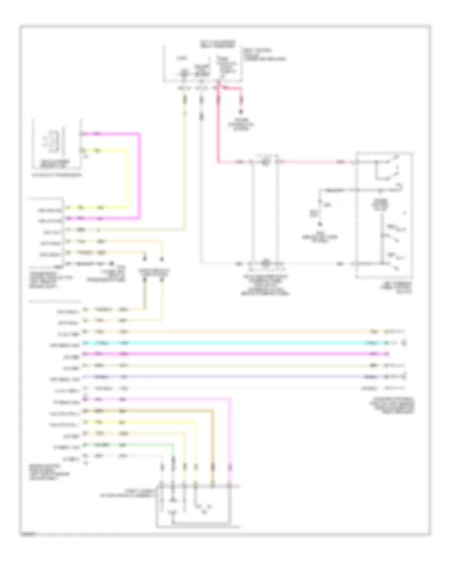
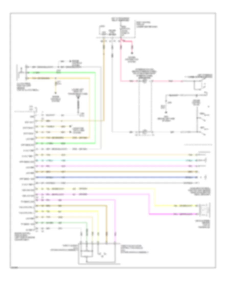
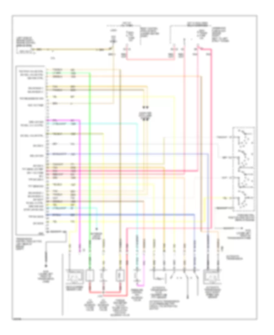
Transmission Wiring Diagram for Pontiac G5 2009
List of elements for Transmission Wiring Diagram for Pontiac G5 2009:
- (left side of engine compt) engine control module (ecm)
- 1-2 shift solenoid (1-2 ss) valve
- 2-3 shift solenoid (2-3 ss) valve
- 2.2l
- Acc vol ctrl
- Acc volt
- Acc voltage
- Automatic transmission
- Automatic transmission fluid pressure (tfp) manual valve position switch
- Automatic transmission fluid temperature (tft) sensor
- Automatic transmission input shaft speed (iss) sensor
- B(+)
- Body control module (bcm) (under center dash)
- Computer data lines system
- D4 x3
- E4 x5
- Ecm/ tcm fuse 10a
- Ecm/ trans fuse 10a
- Exterior lights system
- G105 (lower left front of transmission case)
- Gmlan bus (+)
- Gmlan bus (-)
- Gnd
- Hot at all times
- Hot w/ run/ crnk relay energized
- Ign 1 voltage
- Iss high ctrl
- Iss low sig
- J103
- Logic
- Nca
- Oss high sig
- Oss low sig
- Park/neutral position (pnp) switch (rear of engine)
- Pc sol hi ctrl
- Pc sol vlv lo ctrl
- Pnk
- Pressure control (pc) solenoid valve
- Red
- Stop lmp sw sig
- Sw sig a
- Sw sig b
- Sw sig c
- Sw sig p
- Sw sol valve ctrl
- Tan
- Tcc pwm valve ctrl
- Tcc release sw sig
- Tfp sw sig b
- Tfp sw sig c
- Tft sens low ref
- Tft sens sig
- Torque converter clutch pulse width modulation (tcc pwm) solenoid valve
- Transmission control module (tcm) (left rear of engine compt)
- Underhood fuse block (engine compt, next to left strut tower)
- Vehicle speed sensor (vss)
- X100
TRUNK, TAILGATE, FUEL DOOR
Trunk Release Wiring Diagram for Pontiac G5 2009
List of elements for Trunk Release Wiring Diagram for Pontiac G5 2009:
- (body harness, 5.1 cm from "b" pillar) j330
- (center of rear shelf, near left speaker) g401
- Ajar switch
- Ajar switch signal
- B10
- Body control module (bcm) logic (under center dash)
- Computer data lines system
- Driver information center (dic) display
- G201 (behind left side of dash)
- Gmlan serial data
- Hot at all times
- Instrument panel cluster (ipc)
- Interior lights system
- Logic
- Rear compartment lid release actuator (latch assembly)
- Rear compartment lid release switch
- Release actuator
- Release switch
- Tan
- Trunk pcb relay
- Trunk release relay
- Trunk/ htd seats fuse 20a
- Underhood fuse block (engine compt, next to left strut tower)
WARNING SYSTEMS
Warning Systems Wiring Diagram for Pontiac G5 2009
List of elements for Warning Systems Wiring Diagram for Pontiac G5 2009:
- (body harness, 6.5 cm from auxiliary power outlet console) j337
- (center of rear shelf, near left speaker) g401
- (under driver's seat) g301
- Abs ind
- Acc
- Air bag ind
- Auto
- Battery pos volt
- Bcm 2 fuse 40a
- Body control module (bcm) (under center dash)
- Brake fluid level switch (master cylinder assembly)
- Brake fluid lvl
- Brake ind
- Charge ind
- Computer data lines system
- D12
- Dr lck fuse 26 15a
- Driver door jamb switch (left front door jamb)
- Driver information center (dic) display
- Driver seat belt buckle
- Driver seat belt switch
- E12
- Engine coolant temperature ind
- G201 (behind left side of dash)
- G203 (behind right side of dash)
- G301 (under driver's seat)
- Gmlan serial data
- Ground
- Head
- Hot at all times
- Ign
- Ignition switch
- Inflatable restraint sensing & diagnostic module (sdm) (under center console)
- Instrument panel cluster (ipc)
- Int light fuse 27 10a
- J352
- Key-in ignition switch
- Left rear door jamb switch (sedan) (below left rear door hinges)
- Left seat belt sw
- Left turn
- Left turn ind
- Lf door ajar sw
- Logic
- Low engine oil pressure ind
- Low ref
- Low spd gmlan serial data
- Lr door ajar sw
- Lr turn sig sw sig
- Off
- Off run/crank vol
- Park
- Park brake sw
- Park brake switch (center console, attached to parking brake)
- Park lmp sw sig
- Passenger door jamb switch (right front door jamb)
- Pnk
- Radio
- Red
- Rf door ajar sw
- Right rear door jamb switch (sedan) (below right rear door hinges)
- Right turn
- Right turn ind
- Rr door ajar sw
- Rr turn sig sw sig
- Run
- Seat belt ind
- Serial data
- Start
- Traction off ind
- Turn signal/ multi- function switch
- Underhood fuse block (engine compt, next to left strut tower)
WIPER/WASHER
Wiper/Washer Wiring Diagram for Pontiac G5 2009
List of elements for Wiper/Washer Wiring Diagram for Pontiac G5 2009:
- 87a
- B2 x2
- Body control module (bcm) (under center dash)
- C12 x3
- G101 (left side of engine compt, under coolant reservoir)
- High
- Hot at all times
- Hot w/ run/crank relay energized
- Int
- Logic
- Low
- Mist
- Off
- Park switch
- Pnk
- Power distribution system
- Underhood fuse block (engine compt, next to left strut tower)
- Wash
- Windshield washer fluid pump (lower left side of windshield washer reservoir)
- Windshield washer pump control
- Windshield wiper motor (above master cylinder reservoir)
- Windshield wiper motor park switch signal
- Windshield wiper switch signal 1
- Windshield wiper switch signal 2
- Windshield wiper/washer switch (steering column, on right side)
- Wiper diode
- Wpr fuse 15 10a
- Wpr fuse 25a
- Wpr hi/lo relay
- Wpr on/off relay
- X3 b2

 Čeština
 Dansk
Dansk Deutsch
 Ελληνικά
 English
 English
 Español
 Suomi
Suomi Français
 עברית
עברית Hrvatski
 Magyar
 Italiano
 日本語
日本語 한국어
한국어 Nederlands
 Polski
 Português
 Português
 Română
 Русский
 Slovenčina
 Slovenščina
 Svenska
 Türkçe
 中文 (中国)