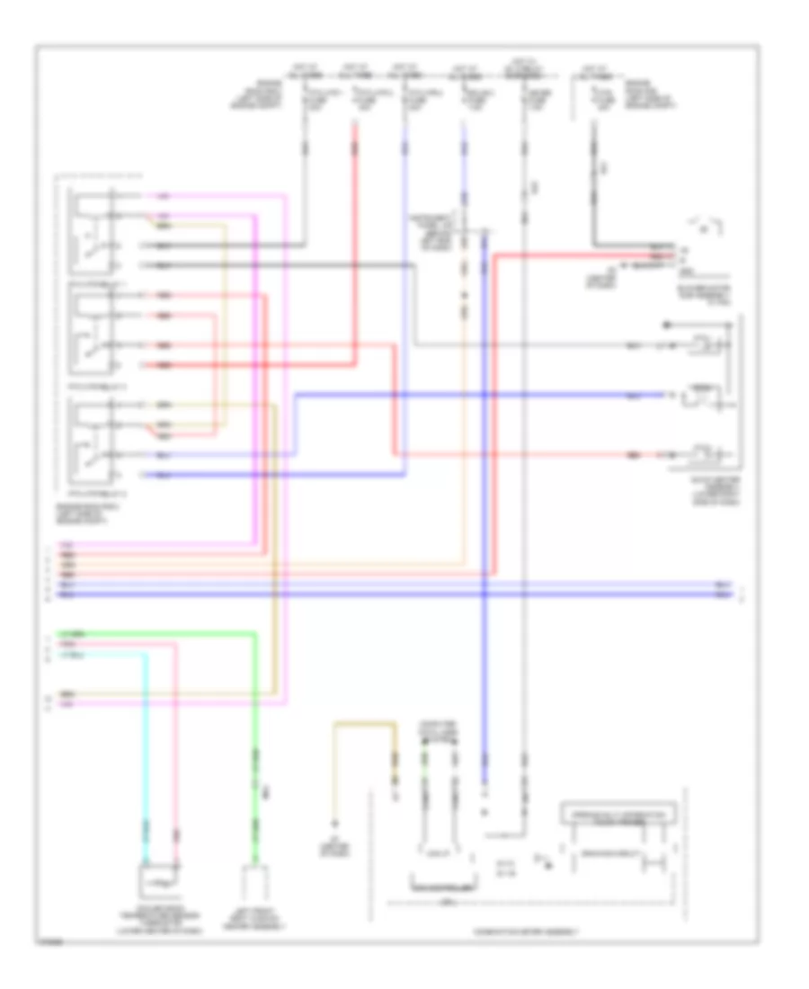
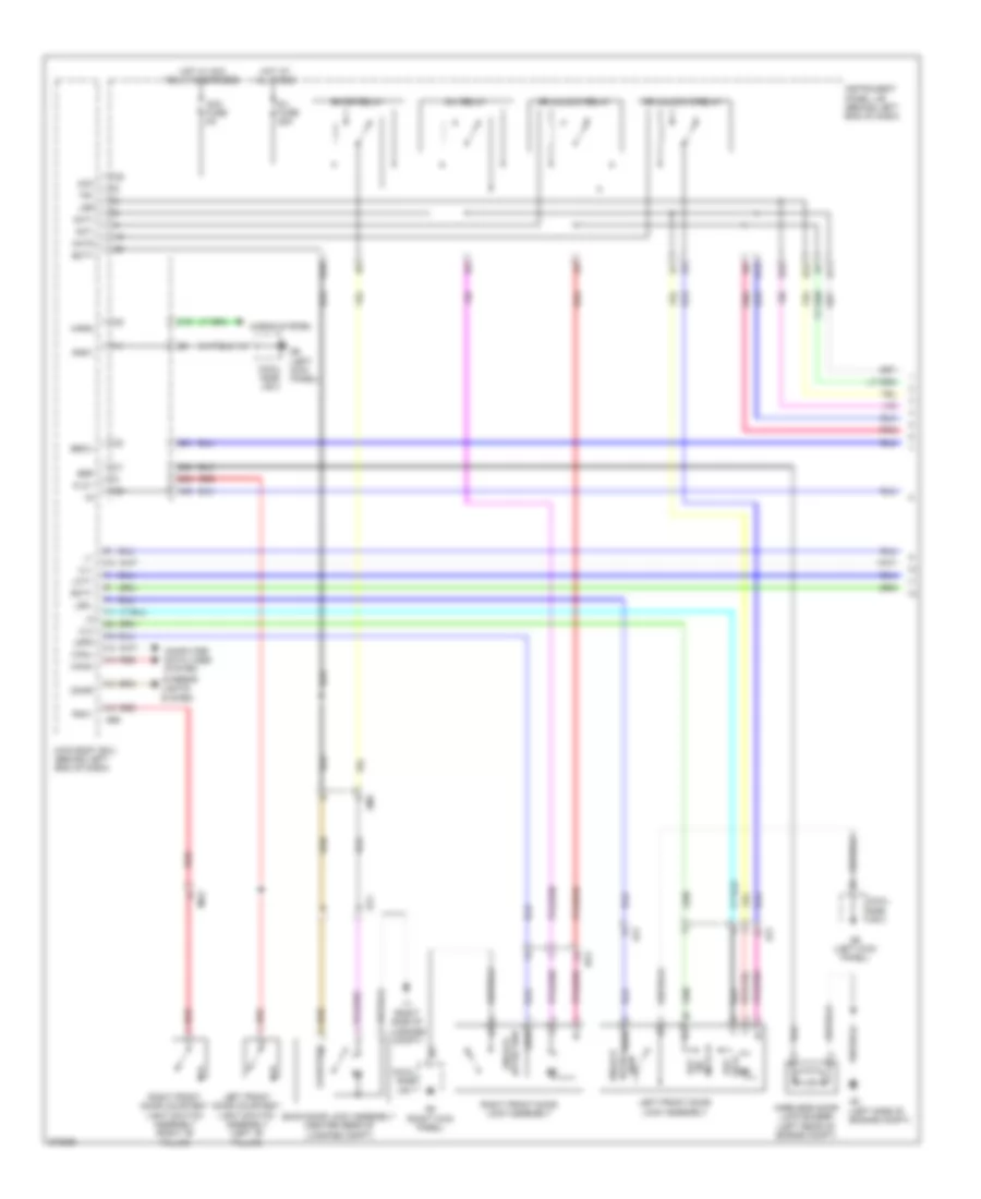
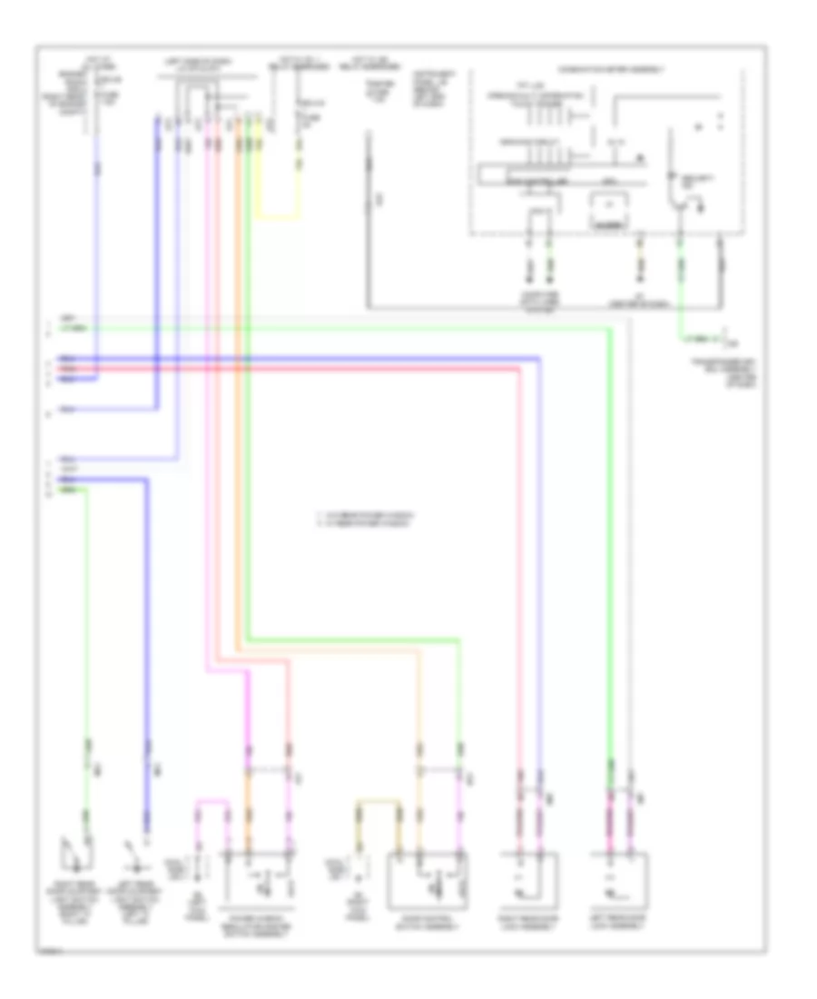
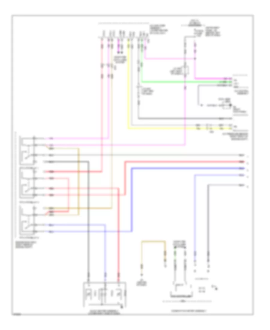
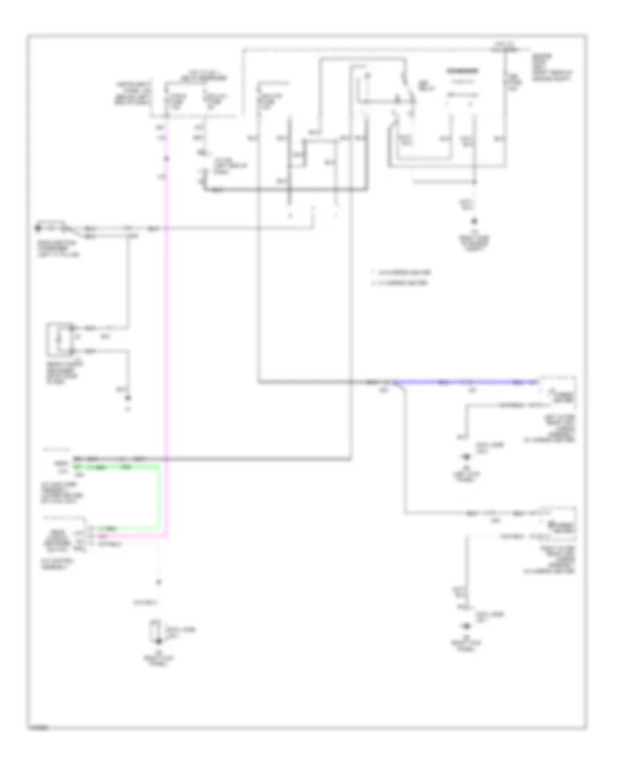
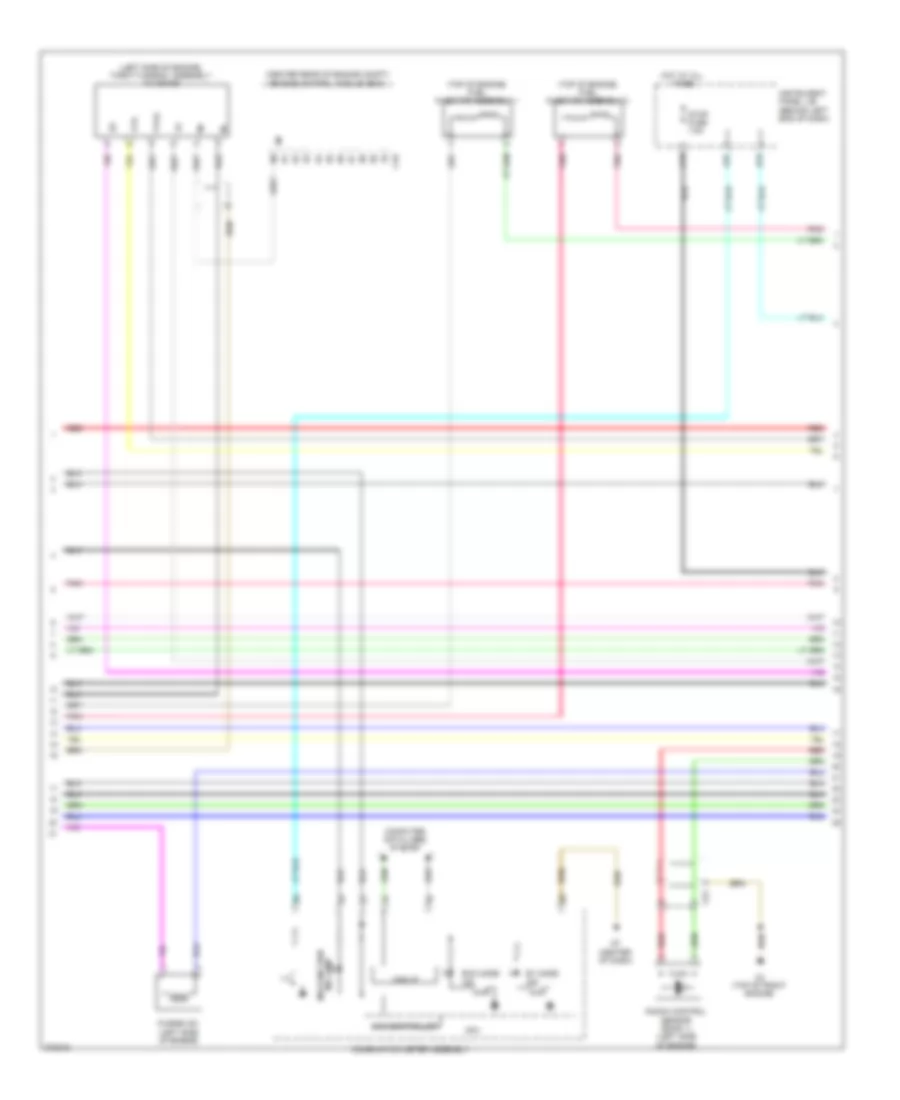
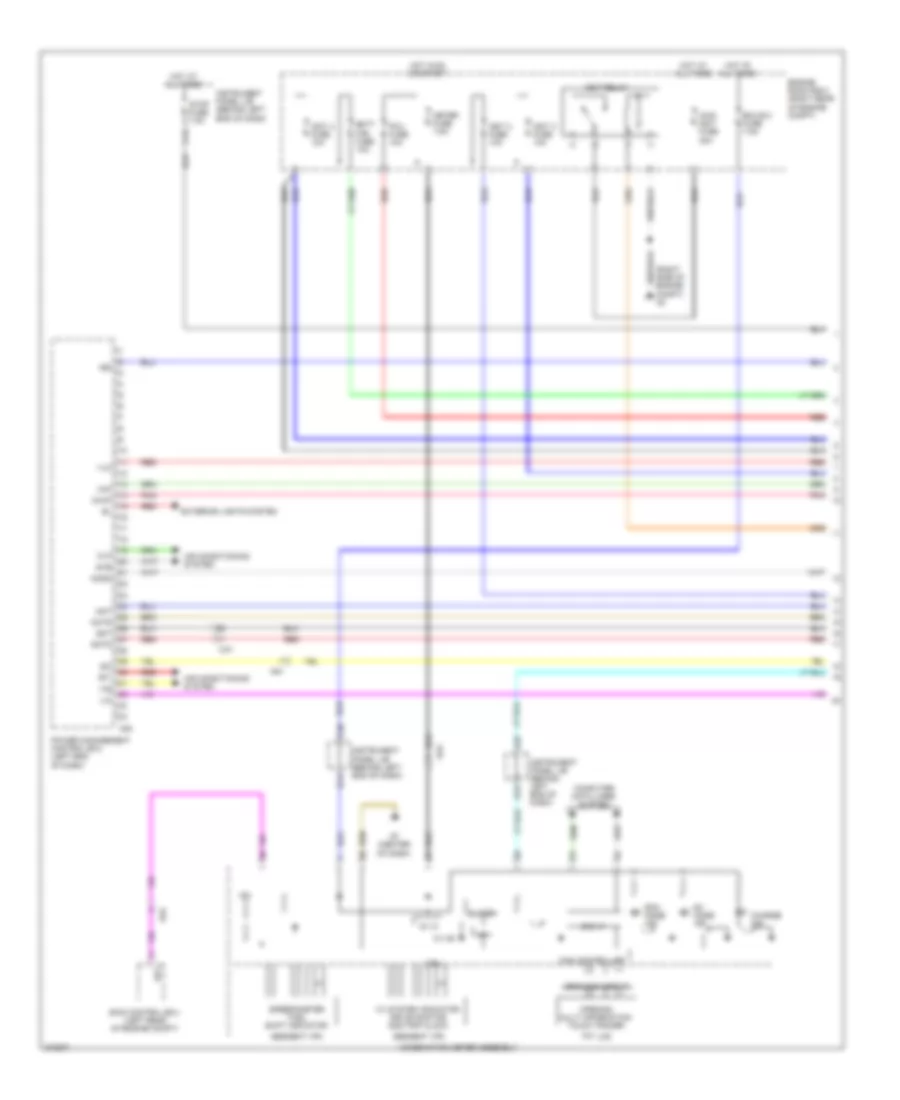
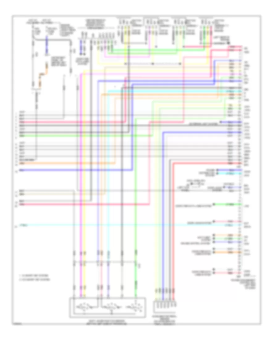
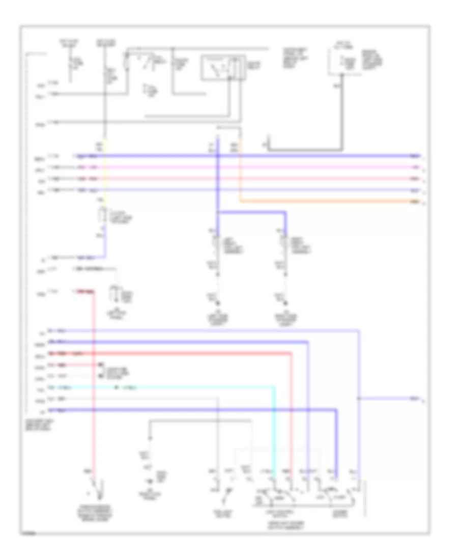
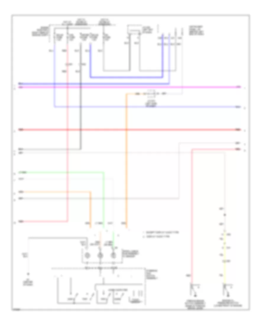
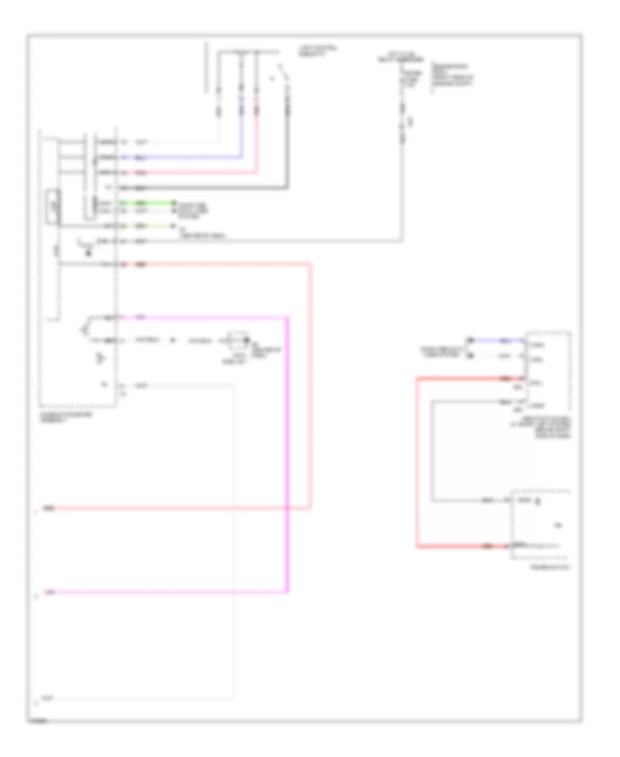
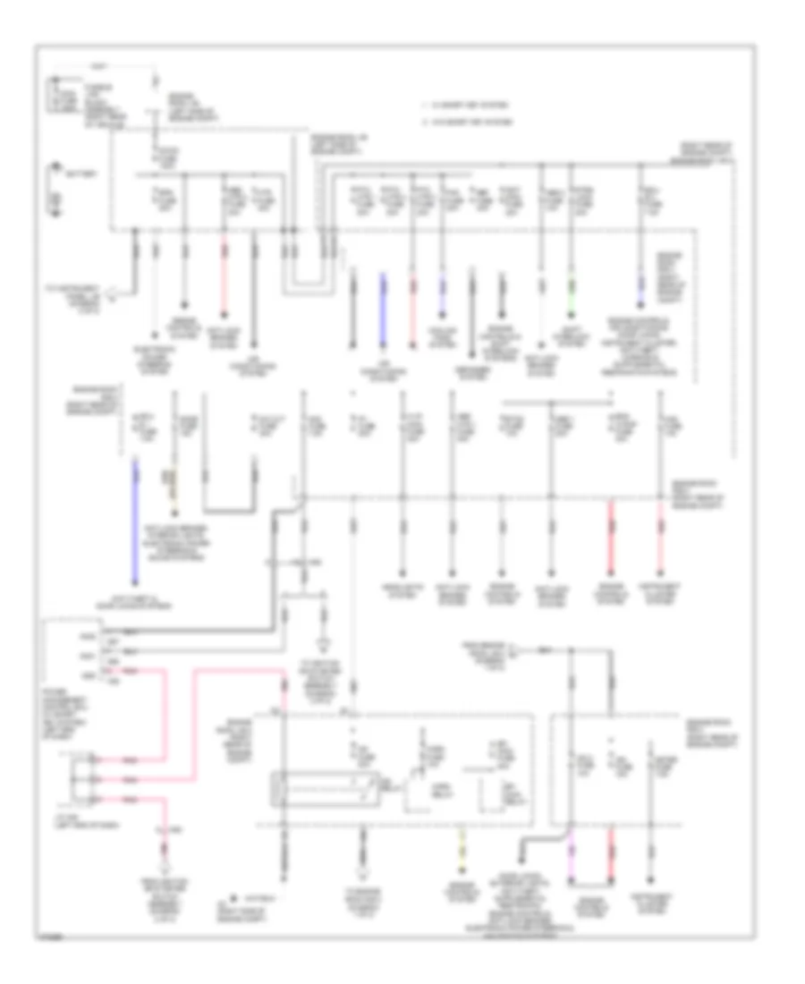
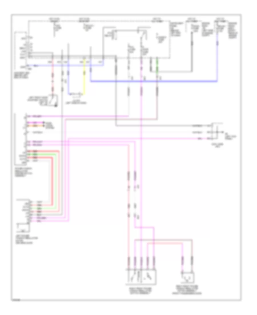
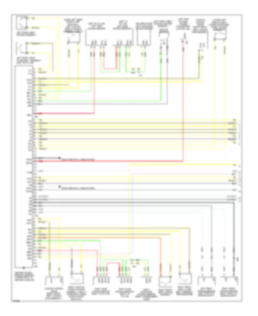
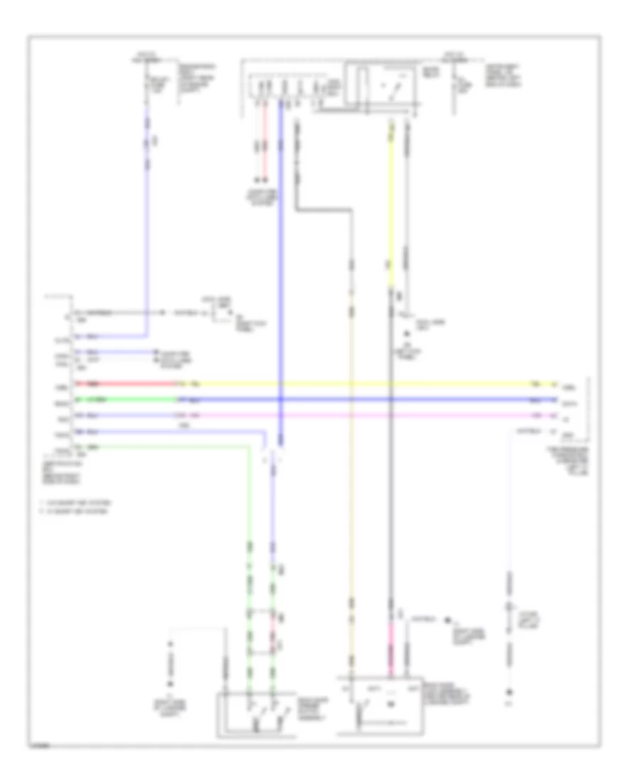
AIR CONDITIONING
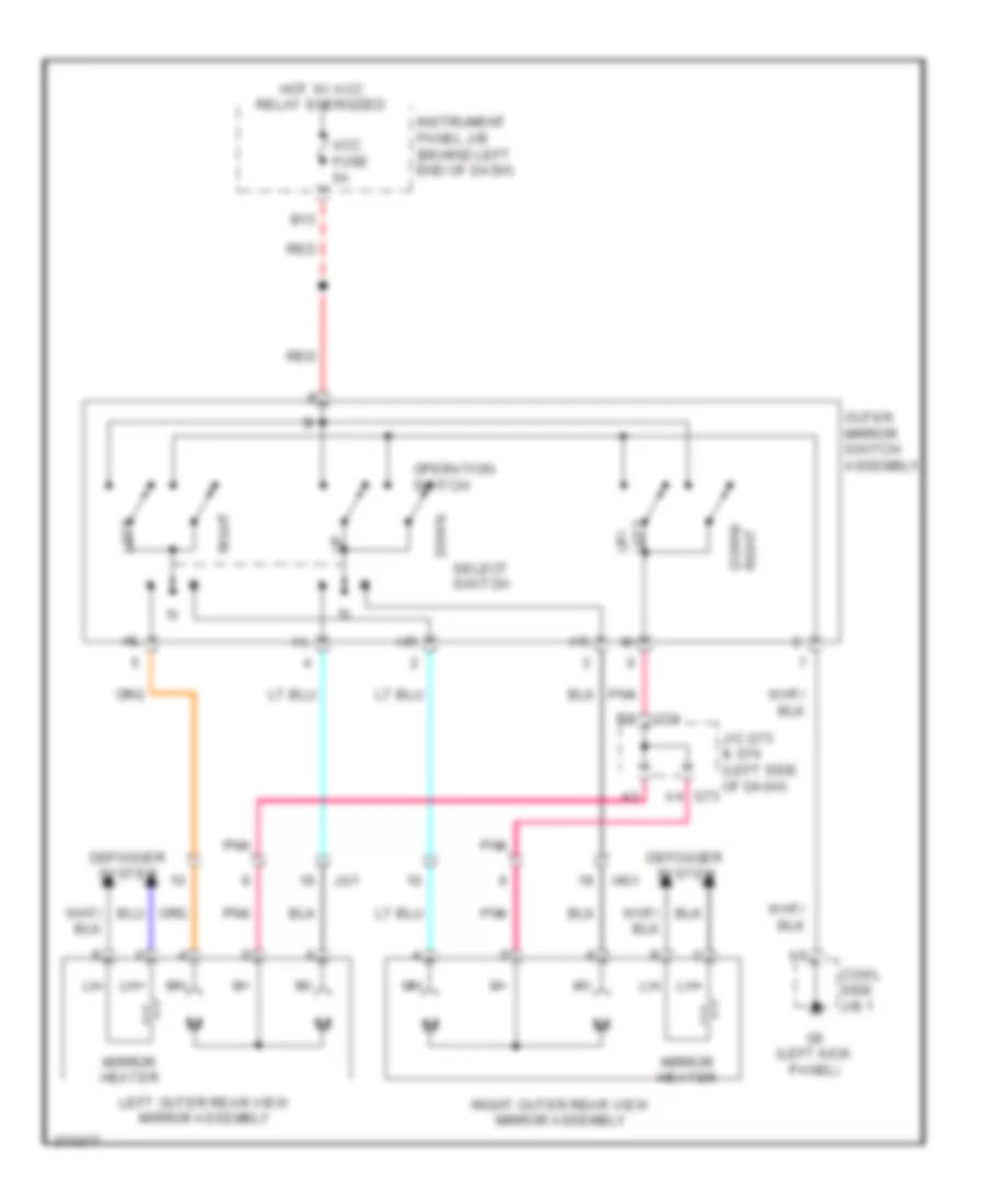
Automatic A/C Wiring Diagram (1 of 3) for Toyota Prius C 2012
 https://portal-diagnostov.com/license.html
Automotive Electricians Portal FZCO
Automotive Electricians Portal FZCO
https://portal-diagnostov.com/license.html
https://portal-diagnostov.com/license.html
Automotive Electricians Portal FZCO
Automotive Electricians Portal FZCO
List of elements for Automatic A/C Wiring Diagram (1 of 3) for Toyota Prius C 2012:
- (right kick panel) g5
- A/c amplifier assembly (lower center of hvac unit)
- A/c control assembly
- A/c evaporator temperature sensor
- A/c pressure sensor (right rear of engine compt)
- A/c unit (a/c harness assembly)
- A51
- Ac1
- Ag3
- Air inlet
- Ambient temperature sensor (thermistor assembly) (behind center of front bumper)
- B bus
- Blw
- Bus
- Bus g
- C15
- Ca1
- Canh
- Canl
- Computer data lines system
- Connector housing color (black)
- Connector housing color (green)
- Cooler (solar sensor) thermistor (lower center of dash)
- Cowl side j/b 1
- Damper servo motor (air inlet)
- Damper servo motor (air mix)
- Damper servo motor (air vent mode)
- Eau
- Eco switch assembly
- Ecos
- G34
- G5 (right kick panel) cowl side j/b 1
- G7 (center of dash)
- Gnd
- Hot w/ ig1 1 relay energized
- Hot w/ ig1 3 relay energized
- Htr-ig fuse 7.5a
- Idh
- Ig+
- Ill+
- Ill-
- Instrument panel j/b (behind left end of dash)
- Interior lights system
- J/c a49 (left end of dash)
- J/c a50 (left end of dash)
- Lin 1
- Lin1
- Micro computer
- Pnk
- Pre
- Ptc1
- Ptc2
- Ptc3
- Red
- S-htr fuse 15a
- S5-3
- S5-4
- Seat heater switch (if equipped)
- Sensor touch
- Sg-1
- Sg-2
- Sga
- Shin
- Spiral cable sub-assembly w/ sensor (on steering column)
- Ss+
- Ss-
- Steering pad switch assembly
- Swo
- Tam
- Tea
- Temperature (+)
- Temperature (-)
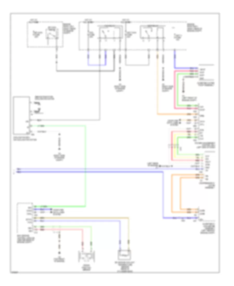
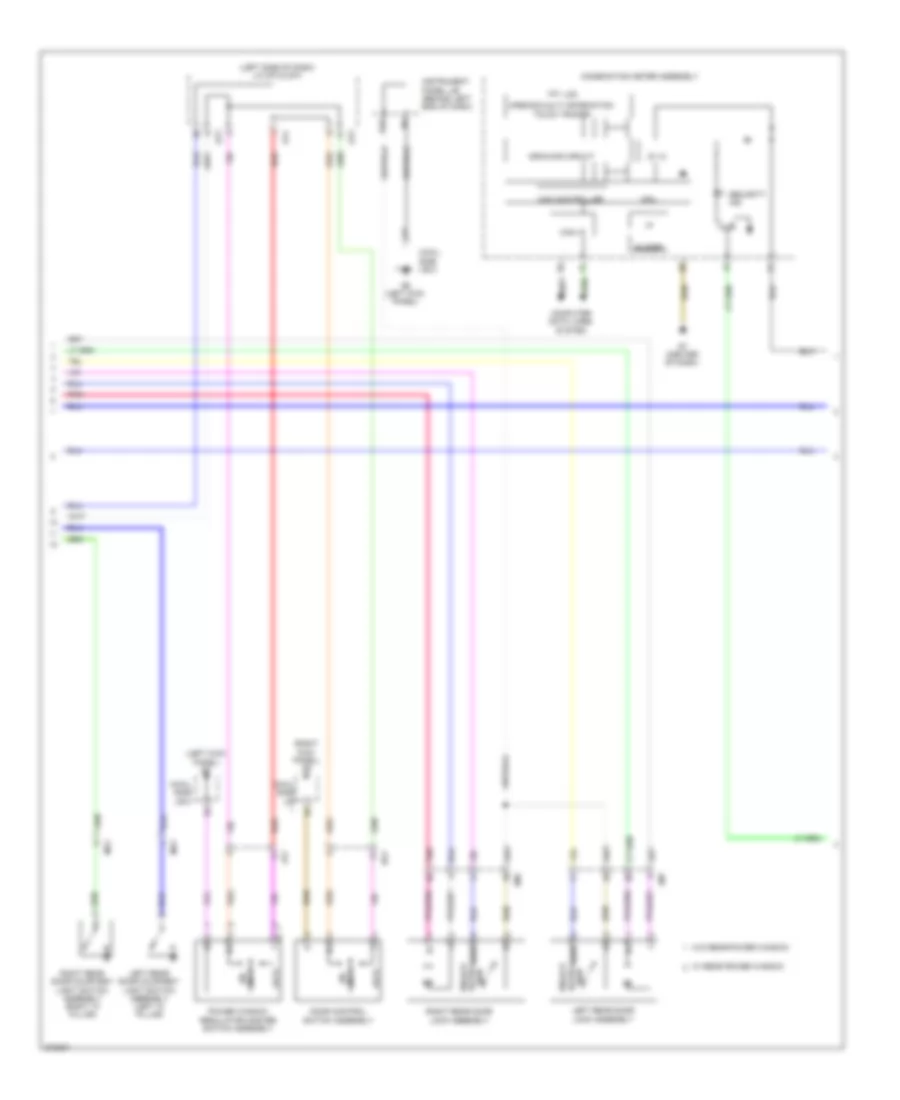
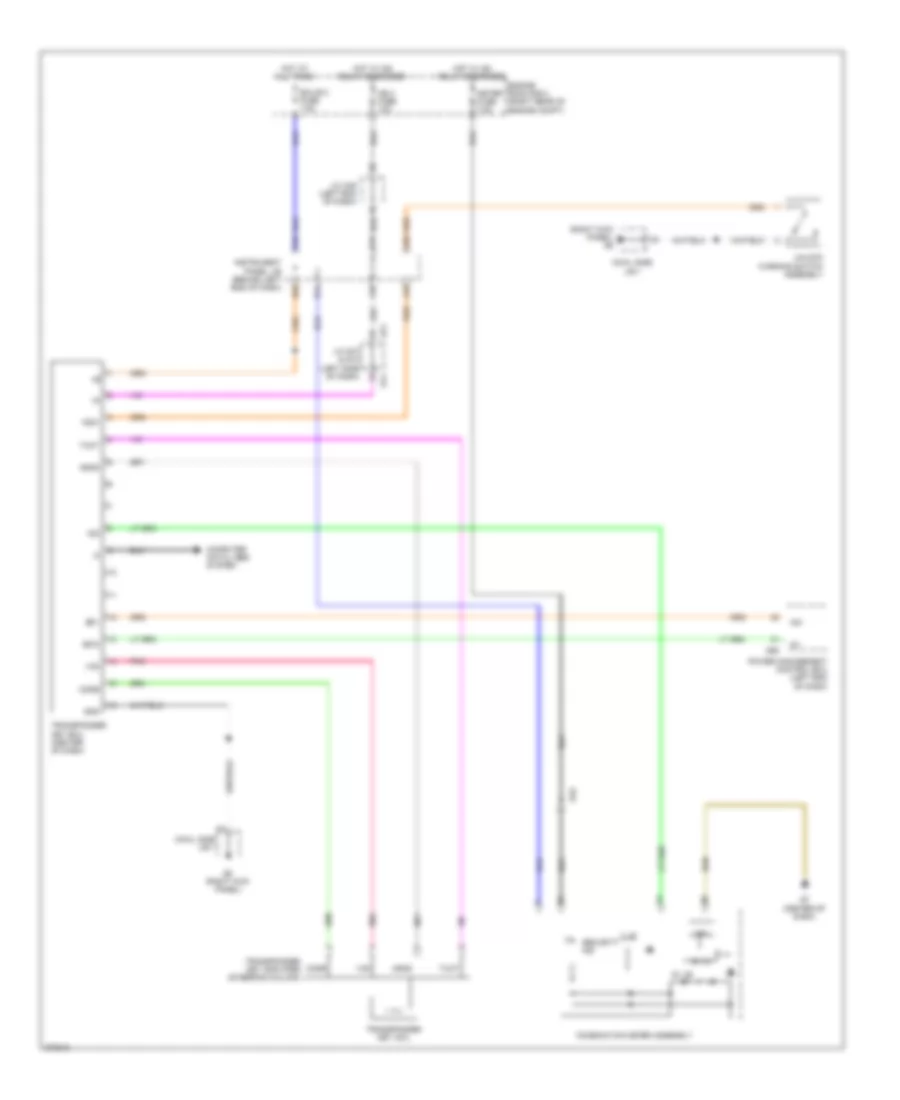
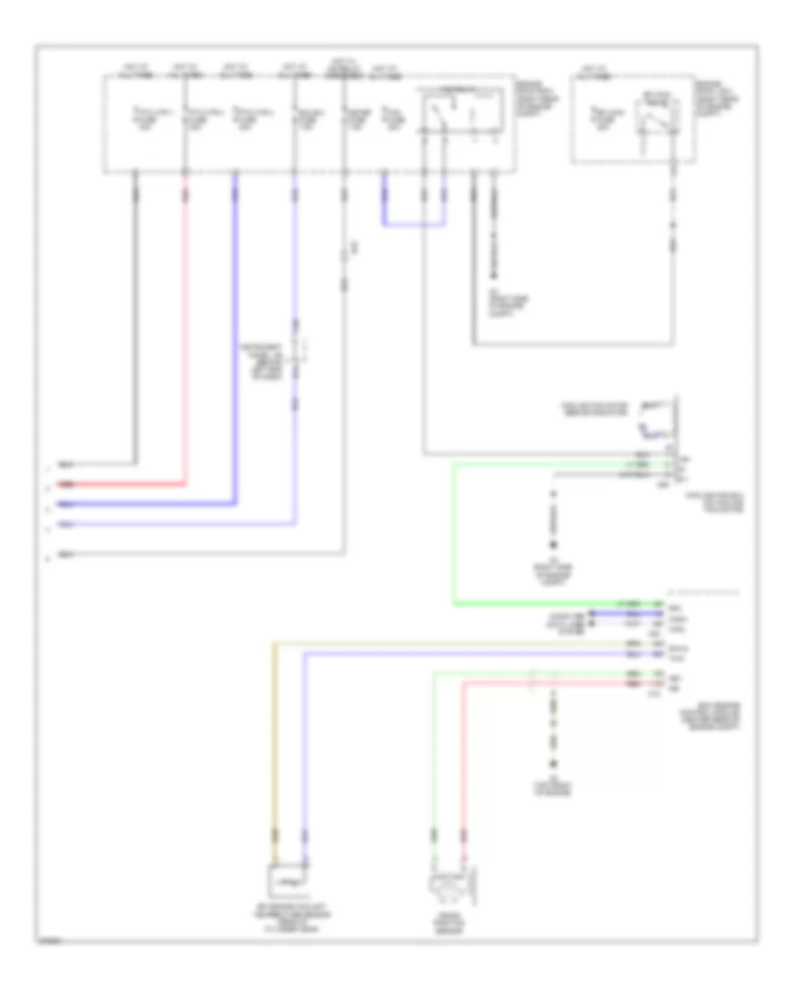
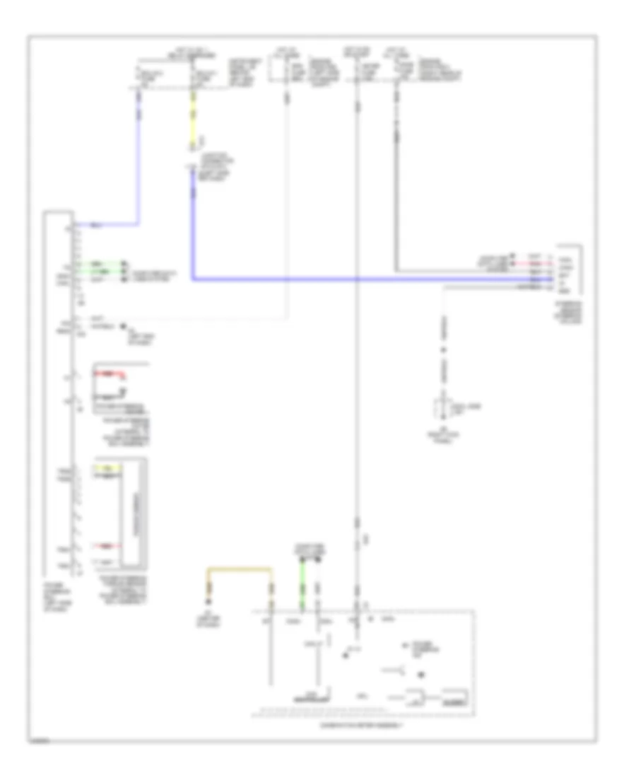
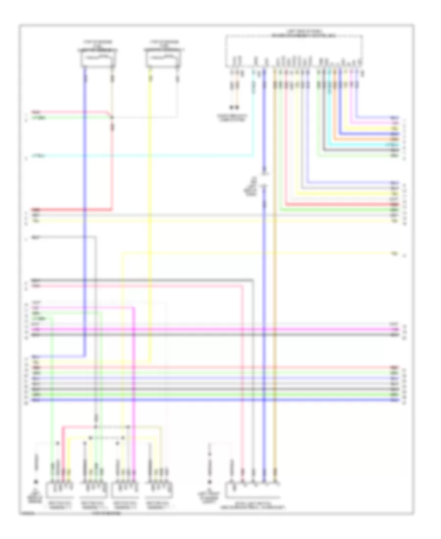
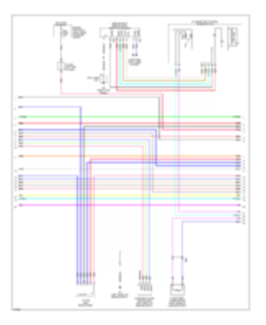
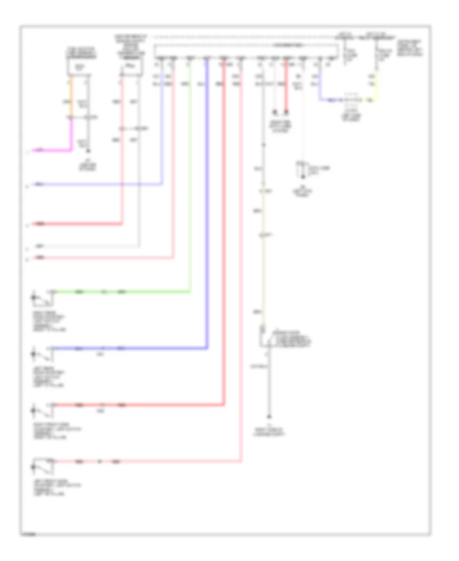
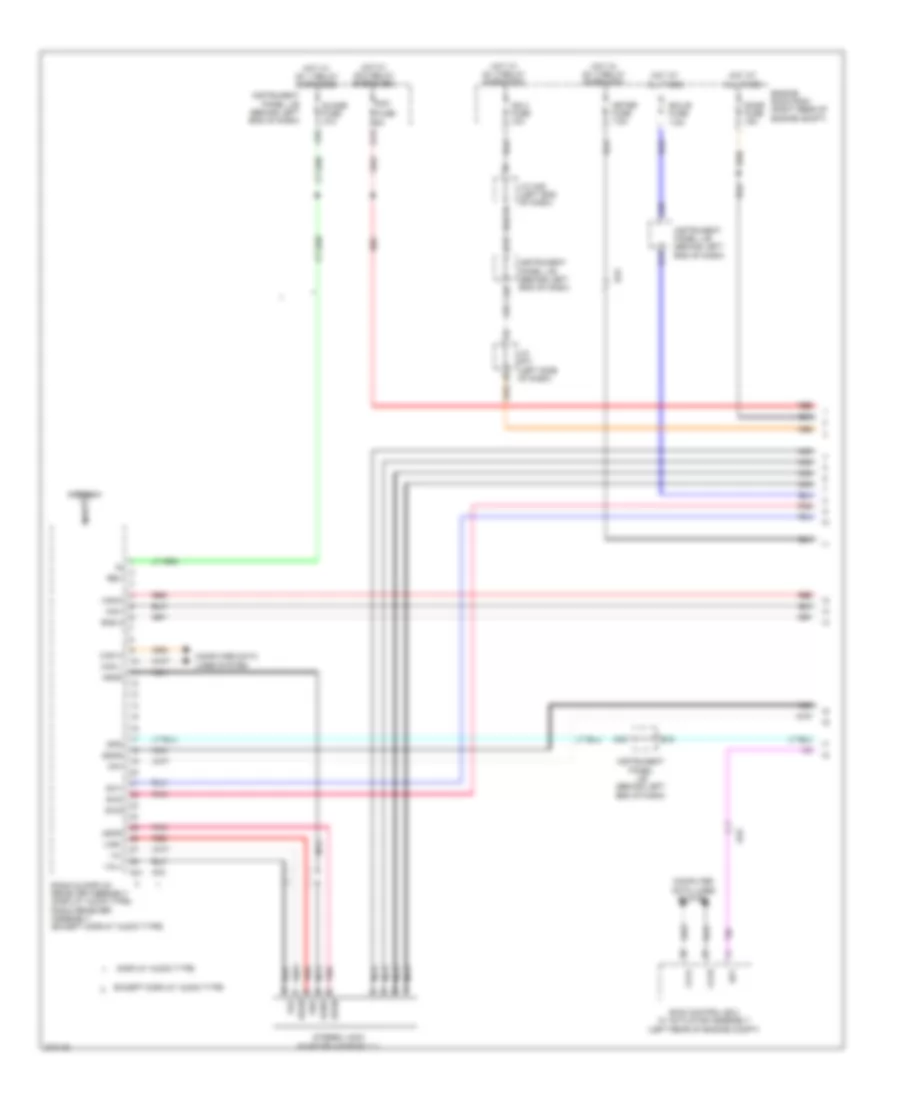
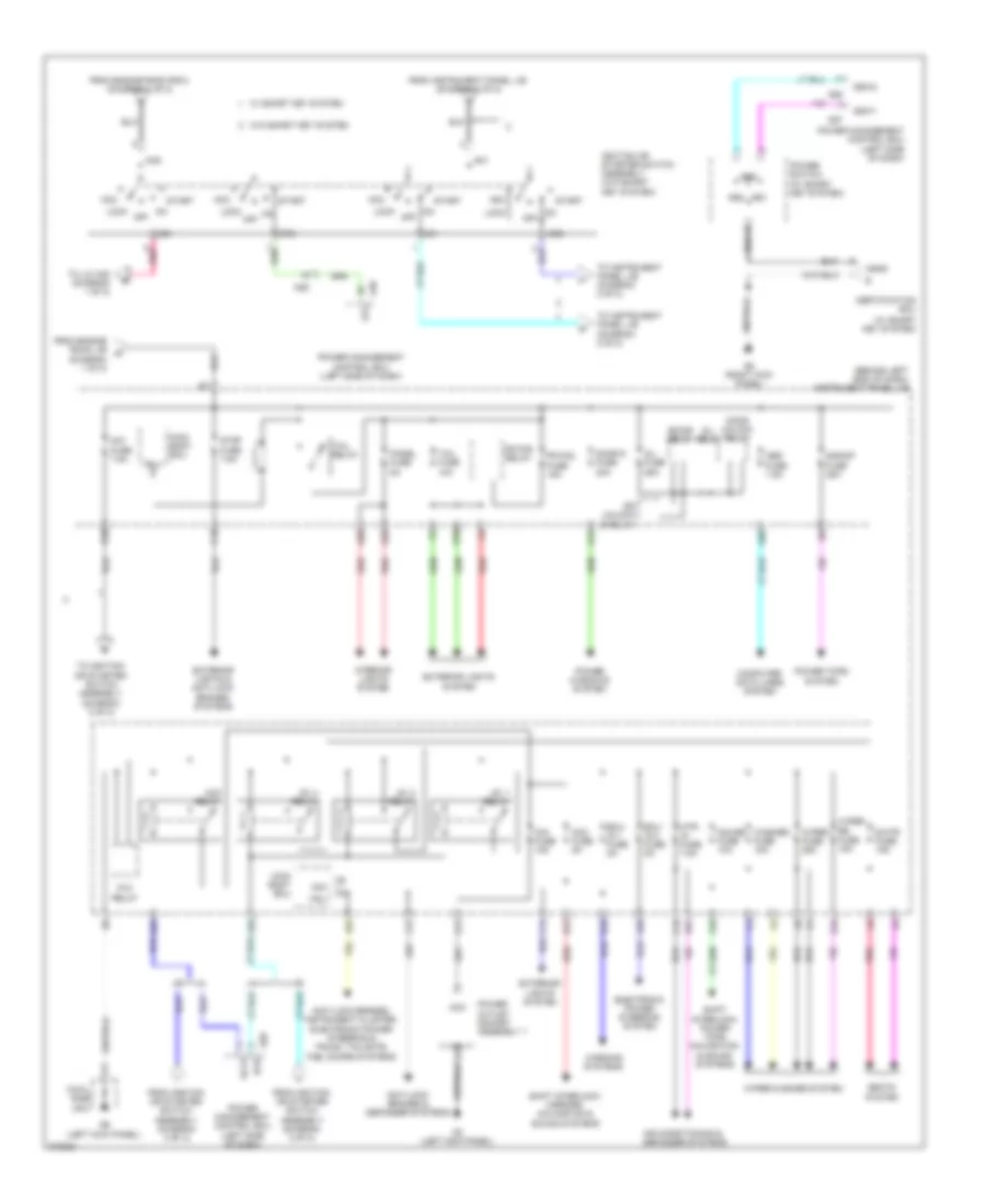
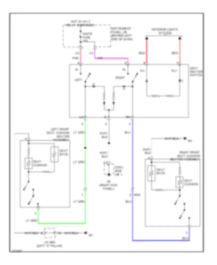
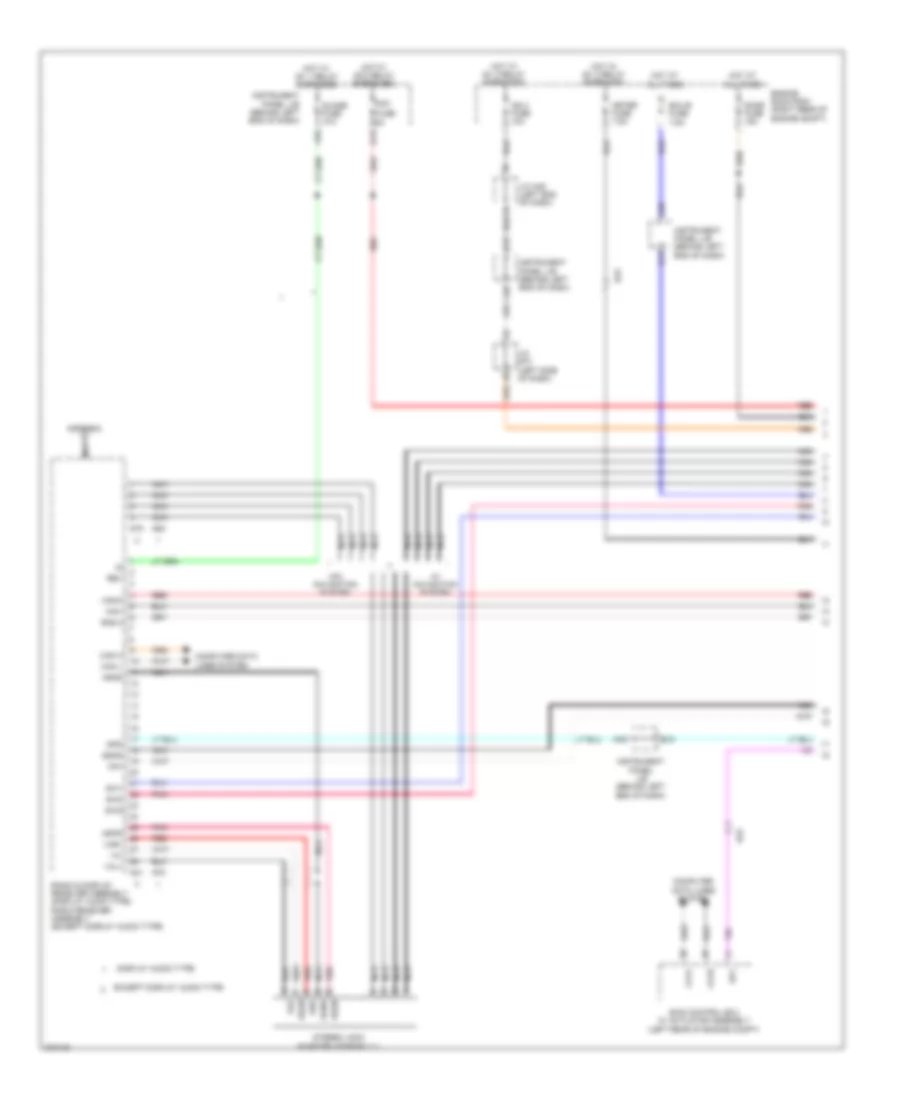
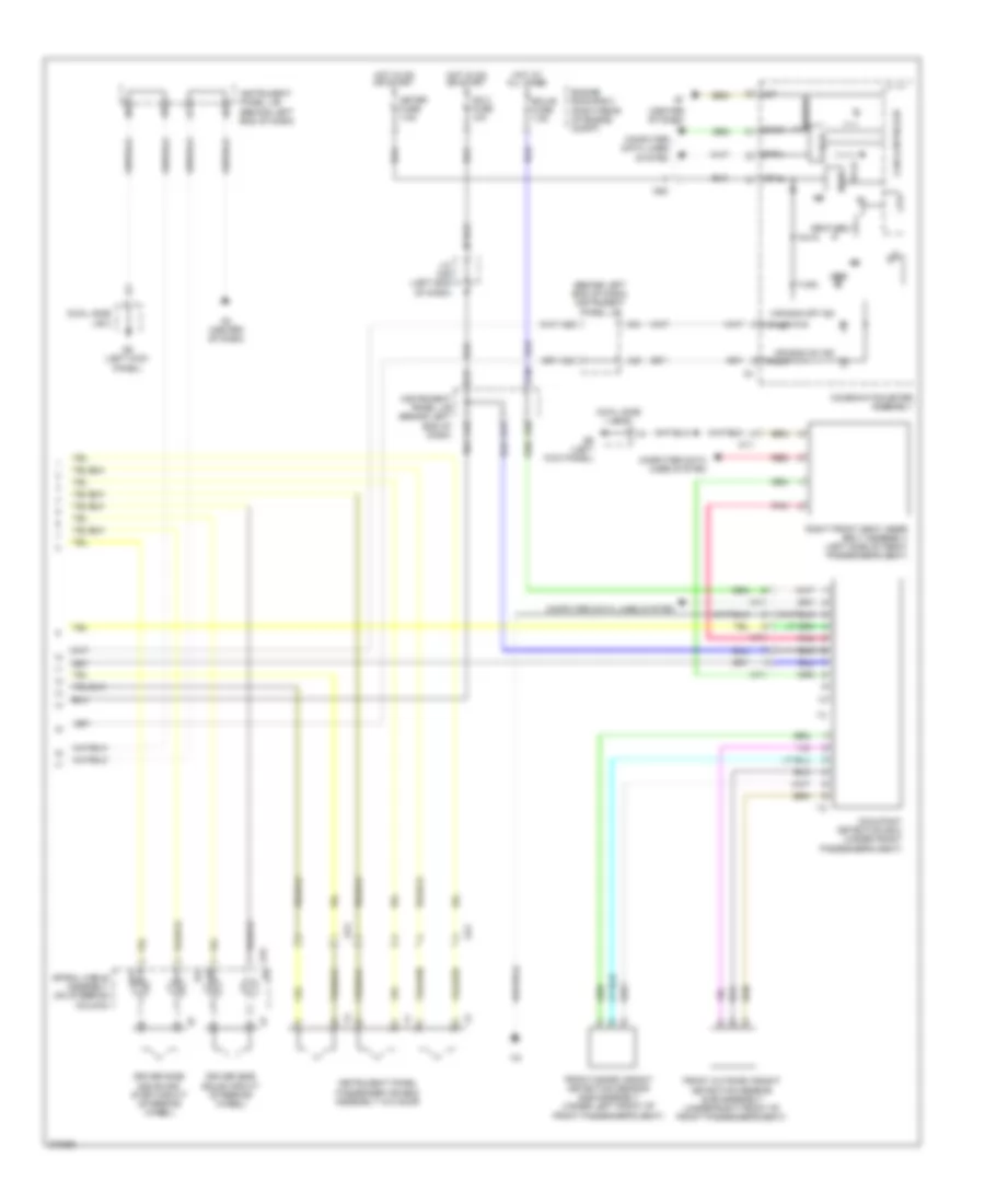
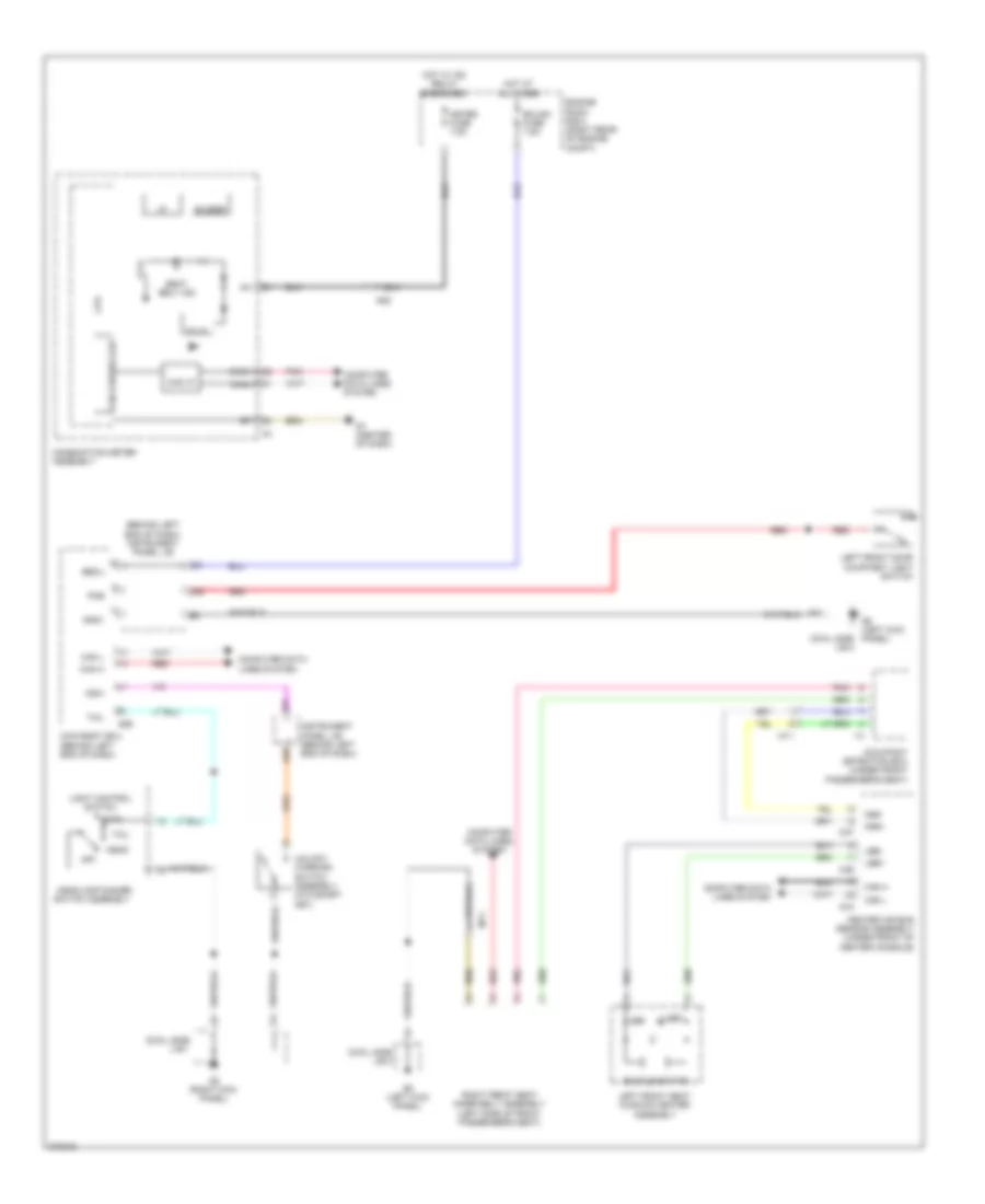
Automatic A/C Wiring Diagram (2 of 3) for Toyota Prius C 2012
List of elements for Automatic A/C Wiring Diagram (2 of 3) for Toyota Prius C 2012:
- 5v +b
- 5v i/c
- Ag1
- Ag2
- B14
- B29
- Blower motor sub assembly w/ fan
- C36
- Can controller
- Can i/f
- Canh
- Canl
- Combination meter assembly
- Computer data lines system
- Cooler (room temperature sensor) thermistor (lower center of dash)
- Cpu
- Drawing circuit
- Ecu-b 2 fuse 7.5a
- Engine room r/b (left side of engine compt)
- Engine room r/b 2 (left side of engine compt)
- G3 (center of dash)
- G7 (center of dash)
- Gnd
- Hot at all times
- Hot w/ ig1 2 relay energized
- Htr fuse 40a
- Ig+
- Instrument panel j/b (behind left end of dash)
- Left front seat cushion heater assembly
- Meter fuse 7.5a
- Mg4
- Opening multi information touch tracer
- Pnk
- Ptc htr 1 fuse 30a
- Ptc htr 2 fuse 30a
- Ptc htr 3 fuse 30a
- Ptc htr relay 1
- Ptc htr relay 2
- Ptc htr relay 3
- Ptc1
- Ptc2
- Ptc3
- Quick heater assembly (lower right side of dash)
- Red
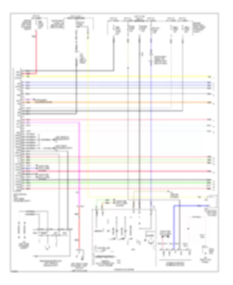
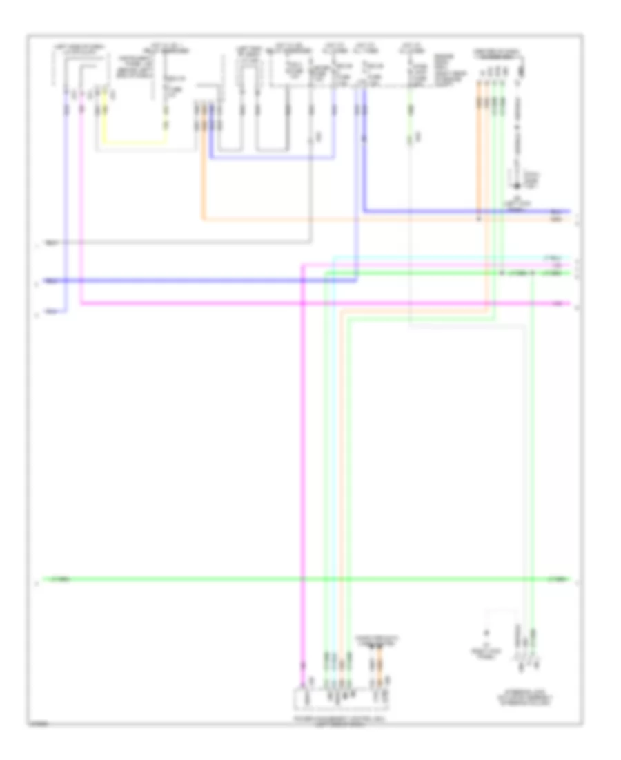
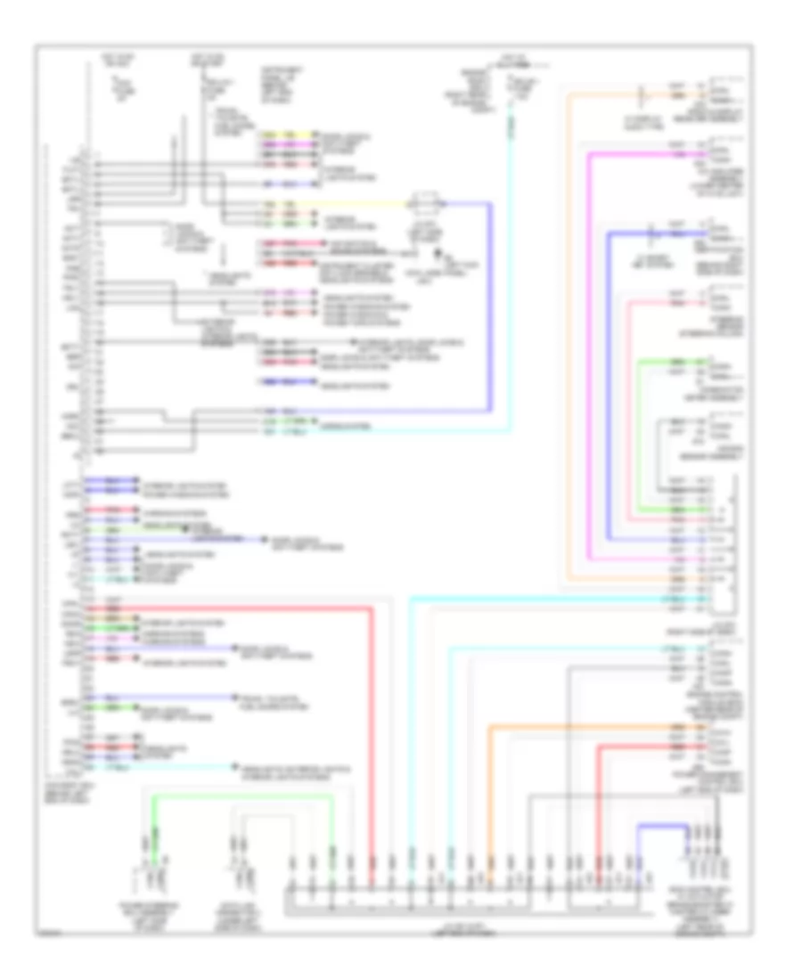
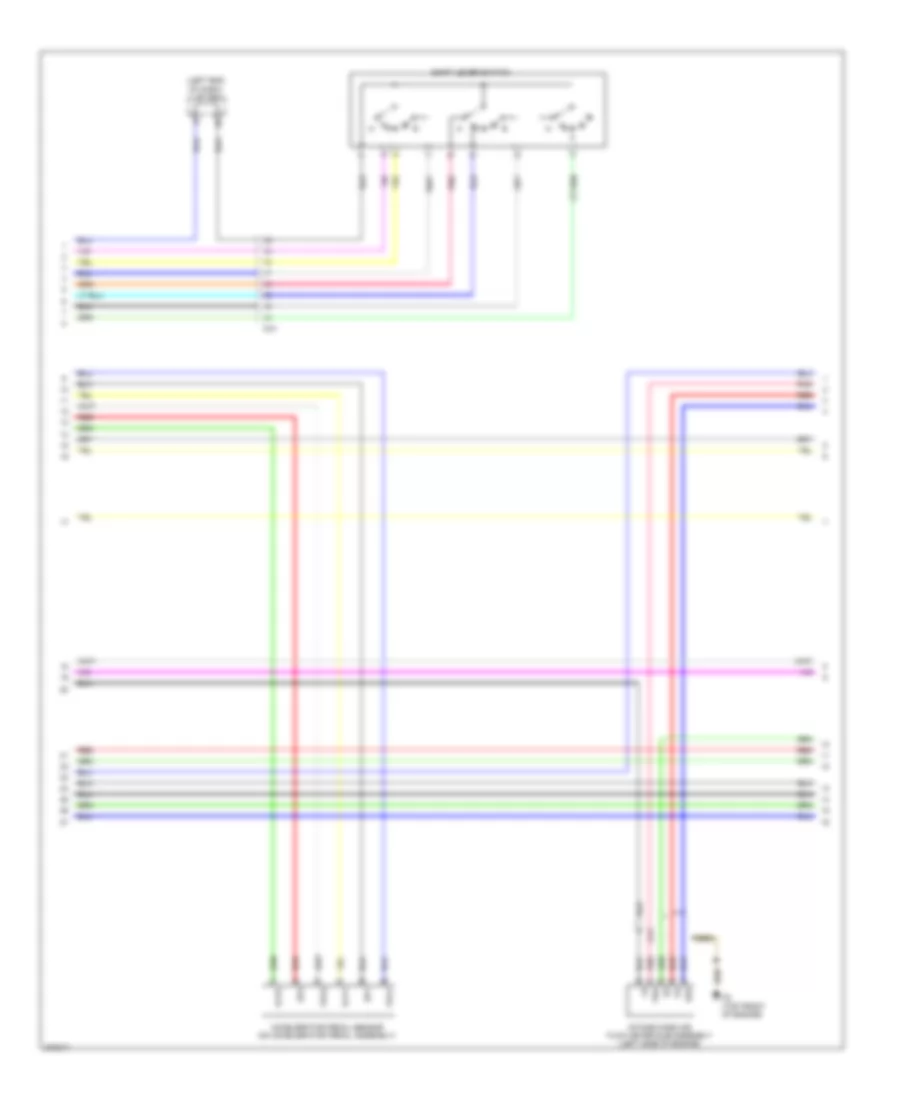
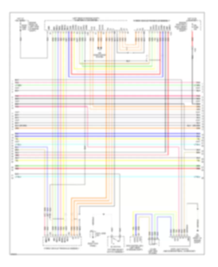
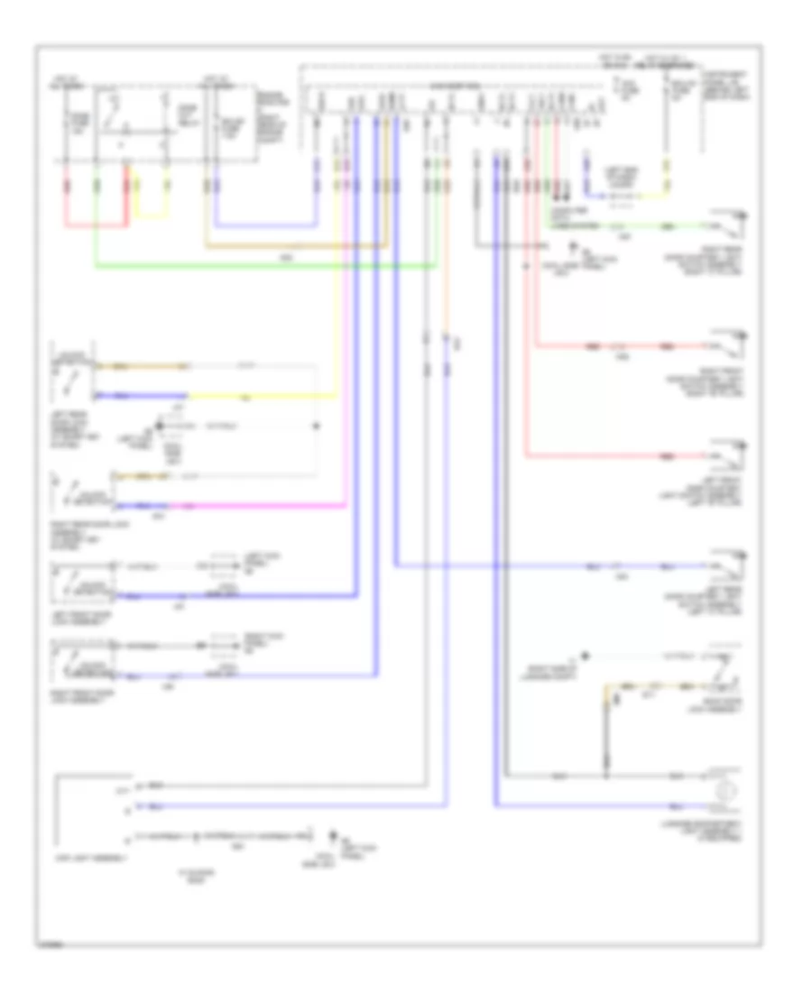
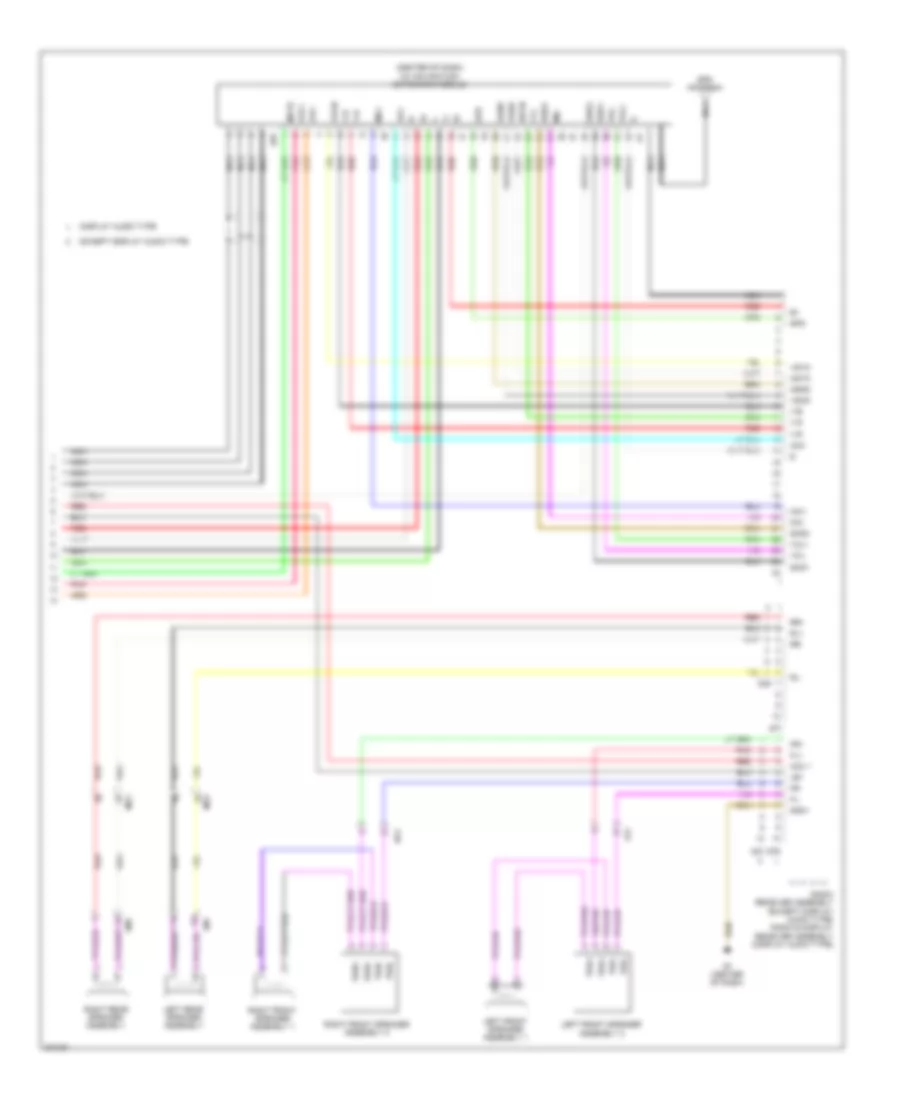
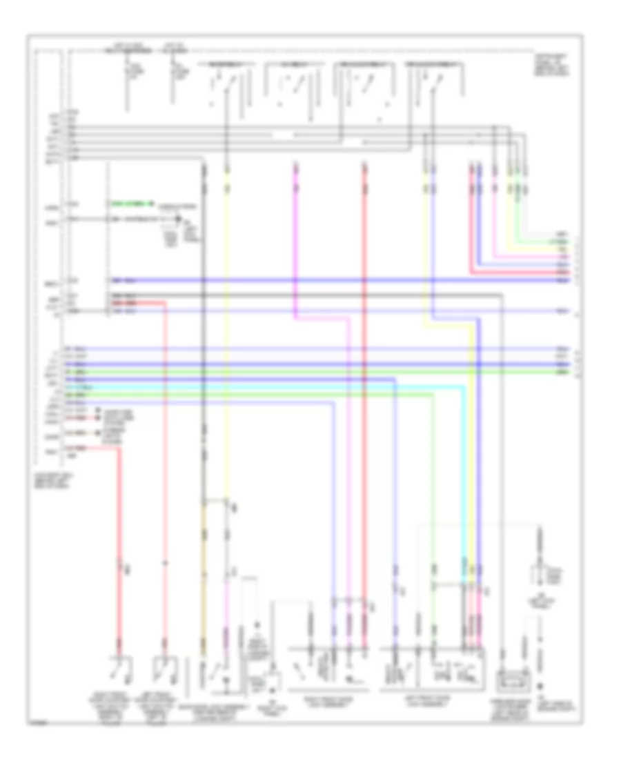
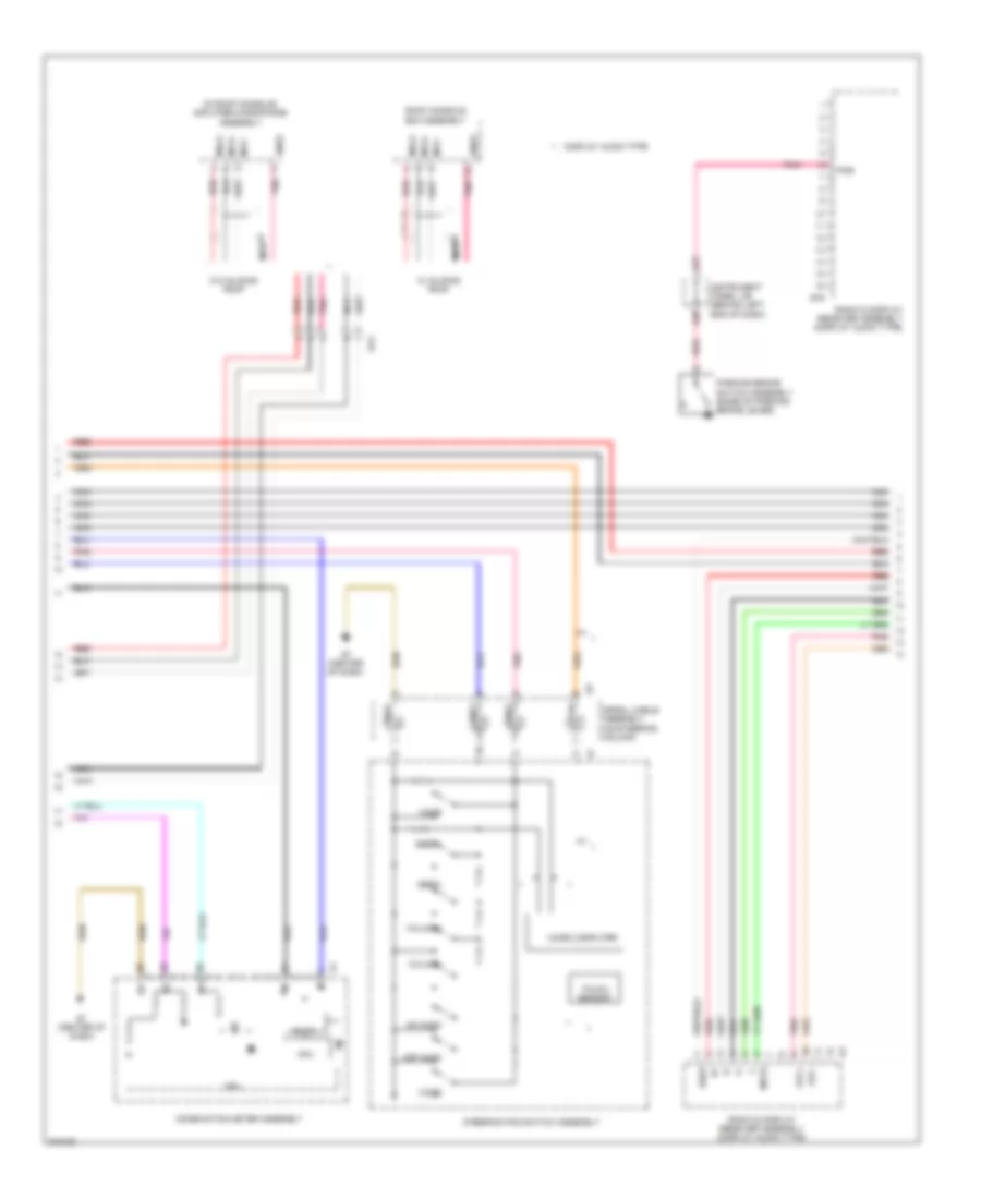
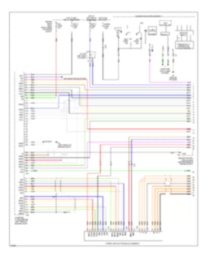
Automatic A/C Wiring Diagram (3 of 3) for Toyota Prius C 2012
List of elements for Automatic A/C Wiring Diagram (3 of 3) for Toyota Prius C 2012:
- (behind radiator) cooling fan motor
- (left rear of engine) c1
- +b1
- +bwp
- A3 (right side of engine compt)
- A38
- A39
- A4 (left front of engine compt)
- A40
- A47
- A52
- Acpb
- Acpe
- Ag3
- C10
- C2 (top front of engine)
- C22
- Ca1
- Ca1h
- Ca1l
- Canh
- Canl
- Clk
- Compressor w/ motor assembly
- Computer data lines system
- Cooling fan ecu (on cooling fan motor)
- Crank position sensor
- Din
- Dout
- Ecm (engine control module) (center rear of engine compt)
- Efi engine coolant temperature sensor (rear of cylinder head)
- Efi main fuse 20a
- Efi main relay
- Engine room j/b 2 (right rear of engine compt)
- Engine room r/b 2 (right rear of engine compt)
- Ethw
- Eti
- Fan fuse 30a
- Fan relay
- G58
- Gnd
- Hot at all times
- Idh
- Ig1
- Igct 3 fuse 10a
- Igct main fuse 30a
- Igct relay
- Inverter w/ converter assembly (left rear of engine compt)
- Inverter water pump assembly
- Ite
- Iwp
- Mrel
- Ne+
- Ne-
- Niwp
- Nwp
- Pnk
- Power management control ecu (left end of dash)
- Red
- Rfc
- Stb
- Stbi
- Swp
- Thw
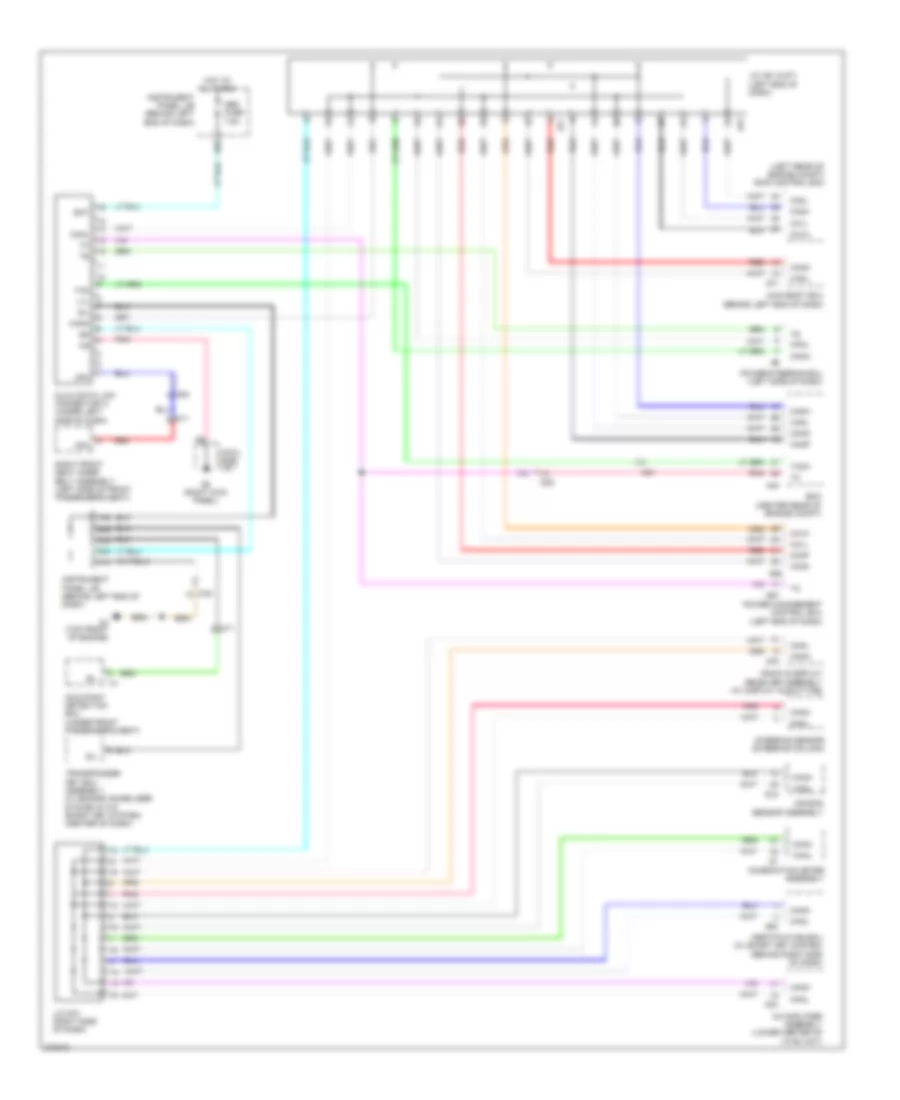
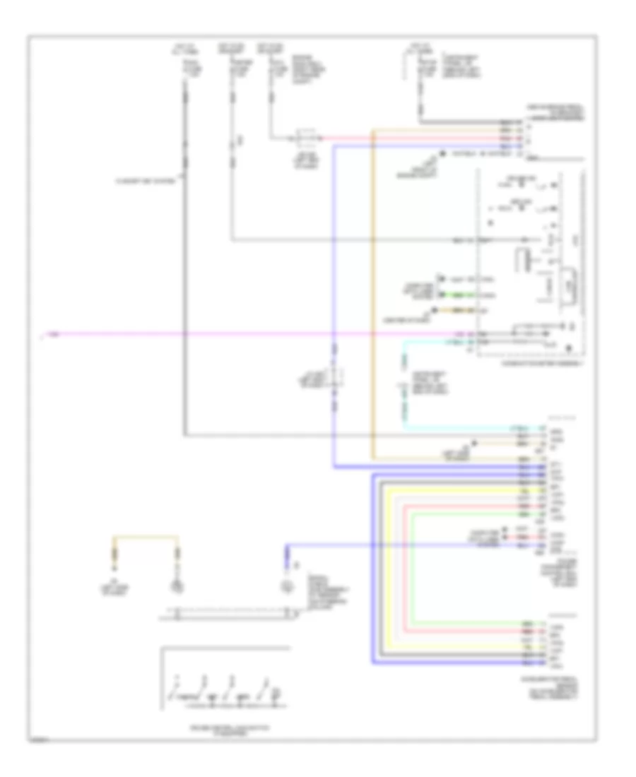
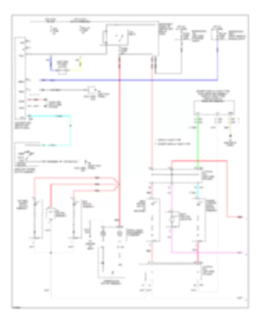
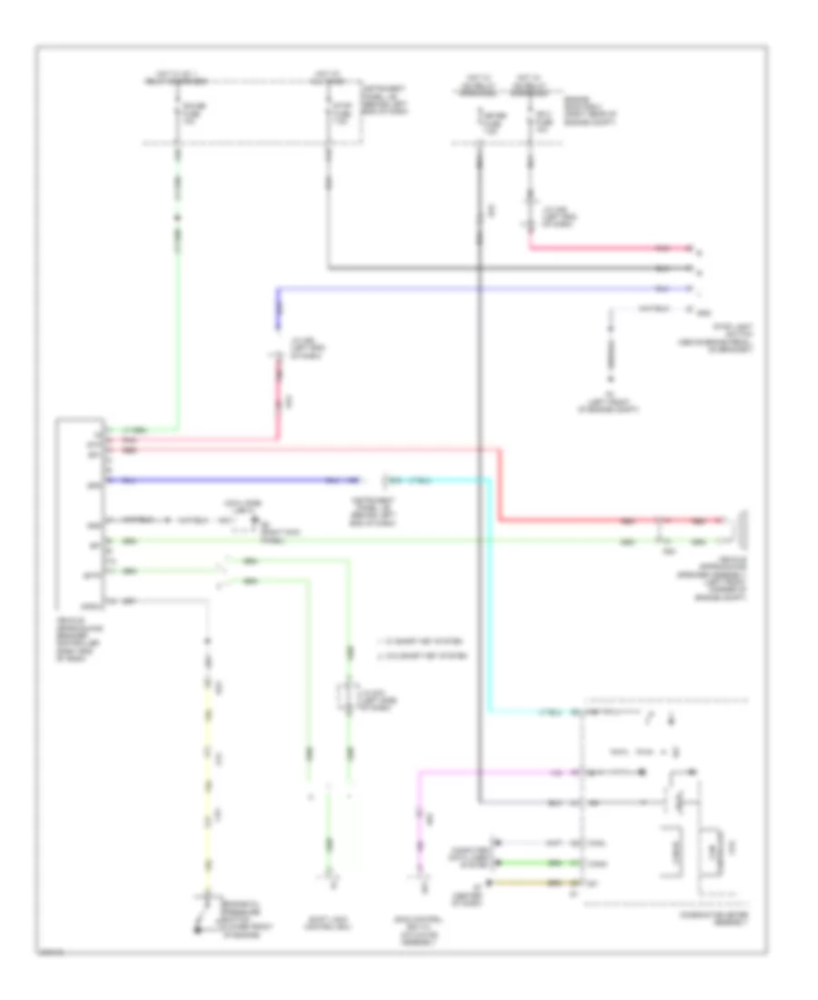
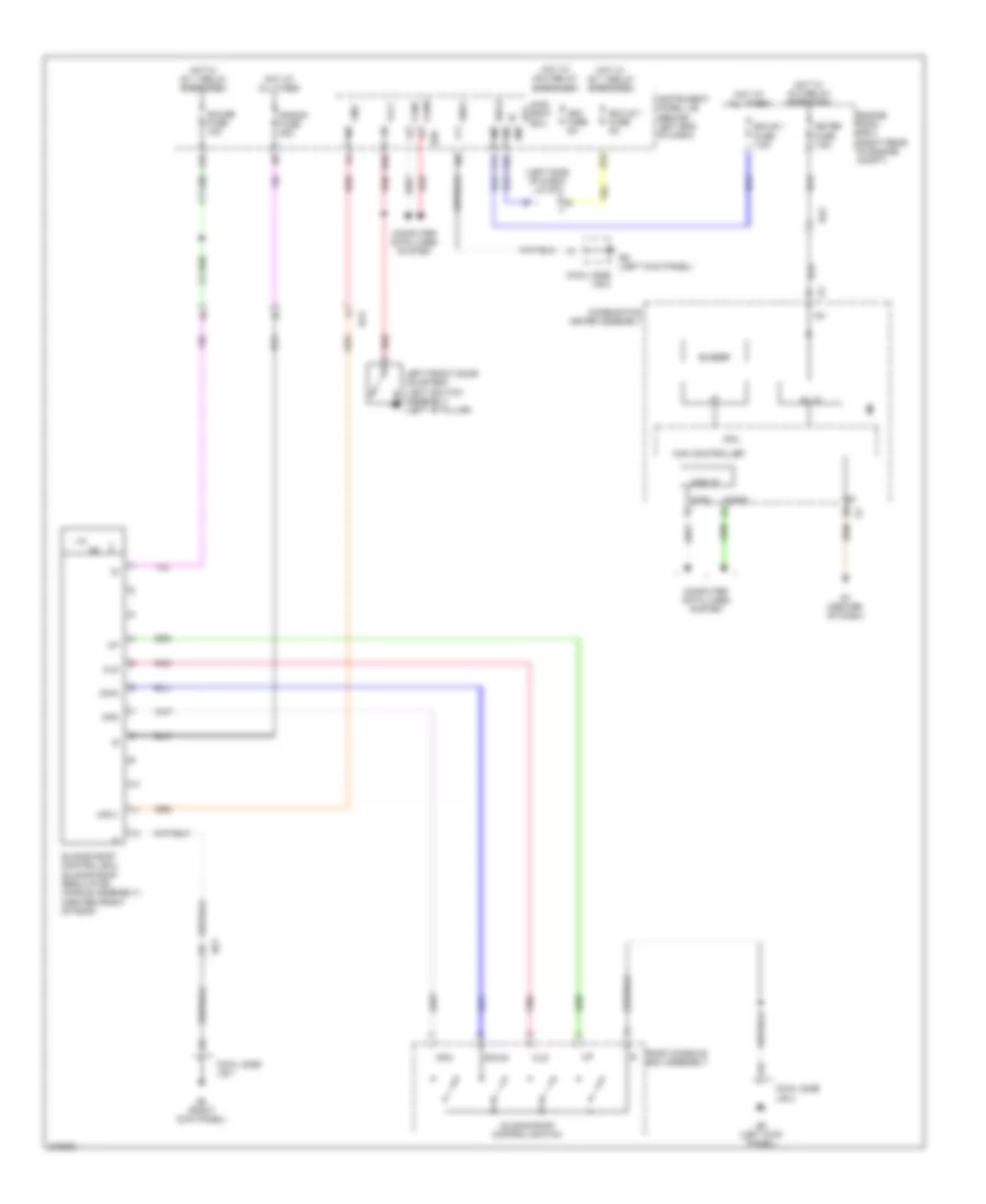
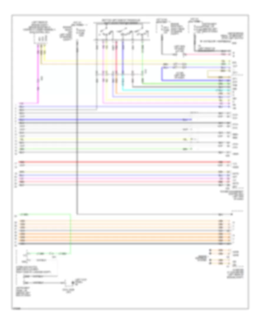
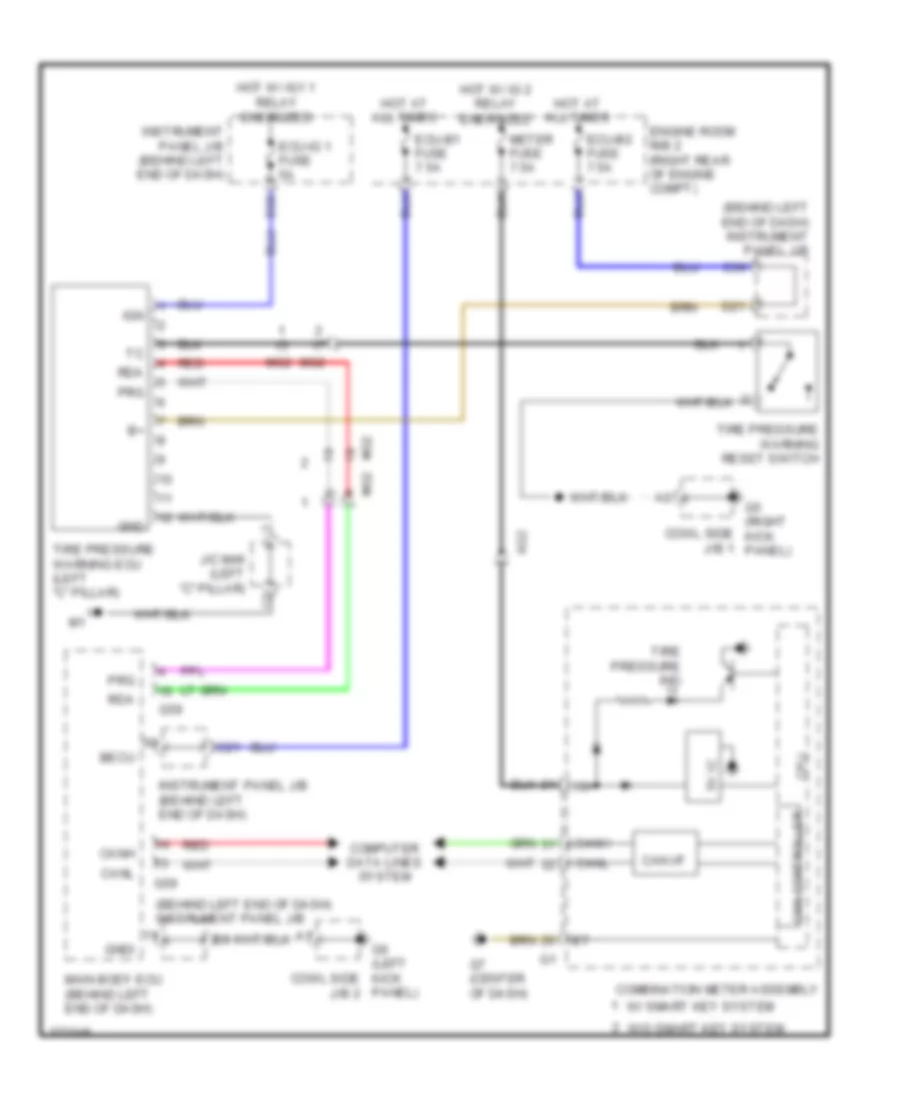
ANTI-LOCK BRAKES
Anti-lock Brakes Wiring Diagram (1 of 2) for Toyota Prius C 2012
List of elements for Anti-lock Brakes Wiring Diagram (1 of 2) for Toyota Prius C 2012:
- (left "b" pillar)
- (left front of engine compt) a4
- (left rear of engine compt) a1
- 5v ic
- A45
- A46
- A5 (left side of engine compt)
- A54
- Abs 1 fuse 20a
- Abs 2 fuse 10a
- Abs ind
- Abs mtr 1 fuse 30a
- Abs mtr 2 fuse 30a
- Ag2
- Am1
- B14
- Bat
- Bm1
- Bm2
- Brake booster pump (left rear of
- Brake ind
- Buzzer
- C27
- C36
- Ca1h
- Ca1l
- Ca2h
- Ca2l
- Can i/f
- Canh
- Canl
- Combination meter
- Computer data lines system
- Controller can
- Cowl side j/b 1
- Cpu
- Cty
- Dome fuse 15a
- Drawing circuit
- Ecu b 2 fuse 7.5a
- Ecu-ig1 fuse 5a
- Engine compt)
- Engine room r/b (left side of engine compt)
- Engine room r/b 2 (right rear of engine compt)
- Ess
- Fl+
- Fl-
- Fr+
- Fr-
- G5 (right kick panel)
- G7 (center of dash)
- G73
- G74
- Gnd
- Gnd1
- Gnd2
- Gnd3
- Gnd4
- Gnd5
- Gnd6
- Hot at all times
- Hot w/ ig1 1 relay energized
- Hot w/ ig2 relay energized
- I/f
- Ig+
- Ig1
- Ig2
- Instrument cluster system
- Instrument panel j/b (behind left end of dash)
- J/c a48 (left end of dash)
- J/c g73 & g74 (left side of dash)
- Lbl
- Left front door courtesy light switch
- Mao2
- Meter fuse 7.5a
- Mri1
- Mri2
- Mro1
- Opening multi information touch tracer
- Pnk
- Red
- Rl+
- Rl-
- Rr+
- Rr-
- Skg
- Skid control ecu (left rear of engine compt)
- Sks
- Sks2
- Slip ind
- Sp1
- Steering sensor (steering column)
- Stp2
- Stpo
- Tft lcd
- Vcsk
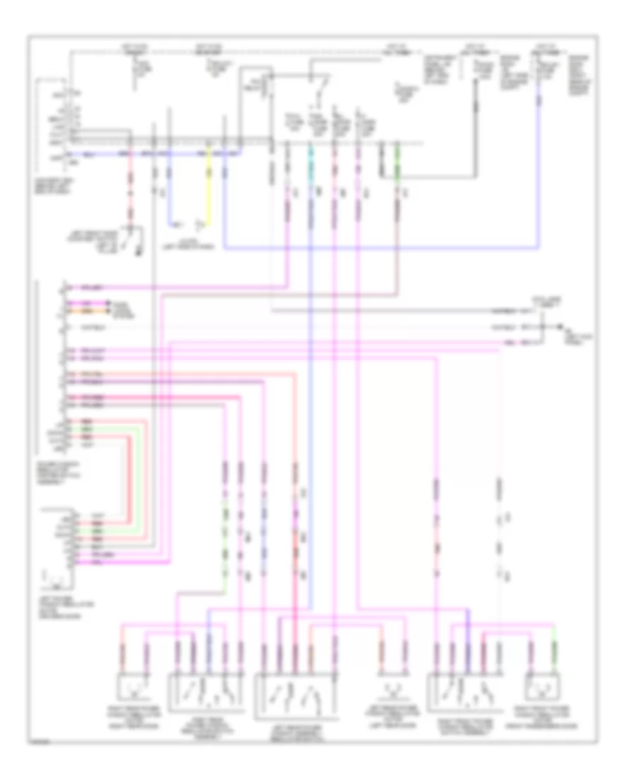
Anti-lock Brakes Wiring Diagram (2 of 2) for Toyota Prius C 2012
List of elements for Anti-lock Brakes Wiring Diagram (2 of 2) for Toyota Prius C 2012:
- (above brake pedal, on bracket) stop light switch assembly
- (right rear wheel hub assembly)
- A1 (left rear of engine compt)
- A28
- A4 (left front of engine compt)
- Acc
- Am1
- Becu
- Brake fluid level warning switch (on brake master cylinder reservoir assembly)
- Brake pedal stroke sensor (above brake pedal)
- C12
- C21
- Canh
- Canl
- Computer data lines system
- Cowl side j/b 2
- Ecu-b 1 fuse 7.5a
- Engine room r/b 2 (right rear of engine compt)
- G59
- G6 (left kick panel)
- Gnd
- Gnd1
- Hot at all times
- Hot w/ ig2 relay energized
- Ig2 2 fuse 10a
- Instrument panel j/b (behind left end of dash)
- J/c a49 (left end of dash)
- J/c a50 (left end of dash)
- Left front speed sensor (left front wheel hub assembly)
- Left rear speed sensor (left rear wheel hub assembly)
- Main body ecu (behind left end of dash)
- Nca
- Out
- Parking brake switch assembly (base of parking brake lever)
- Pkb
- Pnk
- Red
- Right front speed sensor (right front wheel hub assembly)
- Right rear speed sensor
- Skg
- Sks1
- Sks2
- Stop fuse 7.5a
- Vcsk
- Wm1
- Xm1
ANTI-THEFT
Forced Entry Wiring Diagram, with Smart Key System (1 of 4) for Toyota Prius C 2012
List of elements for Forced Entry Wiring Diagram, with Smart Key System (1 of 4) for Toyota Prius C 2012:
- A40
- A5 (left side of engine compt)
- Acc
- Acc fuse 5a
- Act+
- Act-
- Actd
- Back door lock assembly (center rear of luggage compt)
- Bcty
- Becu
- Bk/dr relay
- Bzr
- C19
- C21
- C34
- Canh
- Canl
- Computer data lines system
- Courtesy
- Cowl side j/b 1
- Cowl side j/b 2
- D/l fuse 25a
- D/l relay
- D11
- D12
- D24
- D25
- D35
- D36
- Detection unlock
- Domr
- Dr unlock d relay
- Dr unlock relay
- Flcy
- Frcy
- G5 (right kick panel)
- G59
- G6 (left kick panel)
- Gnd1
- Hg1
- Horn
- Horns system
- Hot at all times
- Hot w/ acc relay energized
- Instrument panel j/b (behind left end of dash)
- Interior lights system
- Jg1
- Lcty
- Left front door courtesy light switch assembly (left "b" pillar)
- Left front door lock assembly
- Lock
- Lock key
- Lsfl
- Lsfr
- Lsr
- Lssr
- Main body ecu (behind left end of dash)
- Mg2
- Pnk
- Rcty
- Red
- Right front door courtesy light switch assembly (right "b" pillar)
- Right front door lock assembly
- Sm1
- St1
- T1 (right side of luggage compt)
- Tion detec- unlock
- Tr+
- Ul1
- Ul3
- Un- key
- Wireless door lock buzzer (left rear of engine compt)
Forced Entry Wiring Diagram, with Smart Key System (2 of 4) for Toyota Prius C 2012
List of elements for Forced Entry Wiring Diagram, with Smart Key System (2 of 4) for Toyota Prius C 2012:
- (left kick panel) g6
- (left side of dash) j/c g73 & g74
- (right kick panel) g5
- 5v ic
- Buzzer
- Can controller
- Can i/f
- Combination meter assembly
- Computer data lines system
- Cowl side j/b
- Cowl side j/b 2
- Cpu
- D26
- Door control switch assembly
- Drawing circuit
- G6 (left kick panel)
- G7 (center of dash)
- G73
- G74
- Hg1
- I/f
- Instrument panel j/b (behind left end of dash)
- Jg1
- Km1
- Left rear door
- Left rear door courtesy light switch assembly (left "c" pillar)
- Lm1
- Lock
- Lock assembly
- Lssr
- Mg1
- Opening multi information
- Pnk
- Power window regulator master switch assembly
- Red
- Right rear door
- Right rear door courtesy light switch assembly (right "c" pillar)
- Security ind
- Tft lcd
- Tion detec- unlock
- Touch tracer
- Un- lock
- W/ rear power window
- W/o rear power window
Forced Entry Wiring Diagram, with Smart Key System (3 of 4) for Toyota Prius C 2012
List of elements for Forced Entry Wiring Diagram, with Smart Key System (3 of 4) for Toyota Prius C 2012:
- (center of dash) id code box
- (left end of dash) j/c a49
- (left side of dash) j/c g73 & g74
- A48
- A54
- Ag2
- B29
- C31
- C36
- Caih
- Cail
- Computer data lines system
- Cowl side j/b 1
- Ecu-b fuse 7.5a
- Ecu-ig fuse 5a
- Efii
- Efio
- Engine room r/b 2 (right rear of engine compt)
- G1 (right kick panel)
- G5 (left kick panel)
- G57
- G58
- G73
- G74
- Gnd
- Hot at all times
- Hot w/ ig1 1 relay energized
- Hot w/ ig2 relay energized
- Ig2 2 fuse 10a
- Imi
- Imo
- Instrument panel j/b (behind left end of dash)
- Lin
- Lin1
- Lin2
- Meter fuse 7.5a
- Power management control ecu (left end of dash)
- Ssw1
- Ssw2
- Steering lock actuator assembly (steering column)
- Strg lock fuse 20a
Forced Entry Wiring Diagram, with Smart Key System (4 of 4) for Toyota Prius C 2012
List of elements for Forced Entry Wiring Diagram, with Smart Key System (4 of 4) for Toyota Prius C 2012:
- (left "c" pillar) tire pressure warning ecu & receiver
- (right kick panel) g5
- Agnd
- Ant1
- Ant2
- Ante7
- Ante8
- Back door opener switch assembly
- Canh
- Canl
- Certification ecu (behind right side of dash)
- Cg1b
- Cg2b
- Cg5b
- Cg6b
- Cg7b
- Cg8b
- Clg1
- Clg2
- Clg5
- Clg6
- Clg7
- Clg8
- Clgb
- Code
- Computer data lines system
- Cowl side j/b 1
- Cowl side j/b 2
- Csel
- Cutb
- Data
- G5 (right kick panel)
- G53
- G54
- G55
- G6 (left kick panel)
- Gg1
- Gnd
- Hg2
- Idw
- Ind
- Indoor electrical key antenna assembly 1
- Indoor electrical key antenna assembly 2
- Indoor electrical key antenna assembly 3
- J/c m46 (left "c" pillar)
- Jg2
- Key coil transponder
- Left front door outside handle assembly
- Lin
- Lock
- Mg1
- Mg2
- Open
- Pnk
- Pos1
- Pos2
- Power switch
- Rco
- Rdam
- Rear electrical key antenna
- Red
- Right front door outside handle assembly
- Sen1
- Sen2
- Sens
- Sm1
- Ss1
- Ss2
- St1
- Swil
- T1 (right side of luggage compt)
- Trg+
- Tsw1
- Tsw2
- Tsw5
- Tsw6
- Txct
- Vc5
Forced Entry Wiring Diagram, without Smart Key System (1 of 2) for Toyota Prius C 2012
List of elements for Forced Entry Wiring Diagram, without Smart Key System (1 of 2) for Toyota Prius C 2012:
- (behind left end of dash)
- A17
- A39
- A40
- Acc
- Acc fuse 5a
- Act+
- Act-
- Actd
- Back door lock assembly (center rear of luggage compt)
- Back door opener switch assembly
- Bcty
- Bdsu
- Becu
- Bk/dr relay
- C19
- C21
- Canh
- Canl
- Computer data lines system
- Courtesy
- Cowl side j/b 1
- Cowl side j/b 2
- D/l fuse 25a
- D/l relay
- D11
- D12
- D35
- D36
- Detection unlock
- Domr
- Dr unlock d relay
- Dr unlock relay
- Flcy
- Frcy
- G5 (right kick panel)
- G59
- G6 (left kick panel)
- Gnd
- Hg1
- Horn
- Horns system
- Hot at all times
- Hot w/ acc relay energized
- Instrument panel j/b
- Instrument panel j/b (behind left end of dash)
- Interior lights system
- Jg1
- Ksw
- Lcty
- Left front door courtesy light switch assembly (left "b" pillar)
- Left front door lock assembly
- Lock
- Lock key
- Lsfl
- Lsfr
- Lssr
- Main body ecu (behind left end of dash)
- Mg2
- Pnk
- Rcty
- Red
- Right front door courtesy light switch assembly (right "b" pillar)
- Right front door lock assembly
- Sm1
- St1
- T1 (right side of luggage compt)
- Tion detec- unlock
- Tr+
- Ul1
- Ul3
- Un- key
- Unlock warning switch assembly
Forced Entry Wiring Diagram, without Smart Key System (2 of 2) for Toyota Prius C 2012
List of elements for Forced Entry Wiring Diagram, without Smart Key System (2 of 2) for Toyota Prius C 2012:
- (left side of dash) j/c g73 & g74
- 5v ic
- A54
- Ag2
- Buzzer
- Can controller
- Can i/f
- Combination meter assembly
- Computer data lines system
- Cowl side j/b 1
- Cowl side j/b 2
- Cpu
- Door control switch assembly
- Drawing circuit
- Ecu-b fuse 7.5a
- Ecu-ig fuse 5a
- Engine room r/b 2 (right rear of engine compt)
- G5 (right kick panel)
- G6 (left kick panel)
- G7 (center of dash)
- G73
- G74
- Hg1
- Hot at all times
- Hot w/ ig1 1 relay energized
- Hot w/ ig2 relay energized
- I/f
- Ind
- Instrument panel j/b (behind left end of dash)
- Jg1
- Km1
- Left rear door
- Left rear door courtesy light switch assembly (left "c" pillar)
- Lm1
- Lock
- Lock assembly
- Meter fuse 7.5a
- Mg1
- Opening multi information
- Pnk
- Power window regulator master switch assembly
- Red
- Right rear door
- Right rear door courtesy light switch assembly (right "c" pillar)
- Security ind
- Tft lcd
- Touch tracer
- Transponder key ecu assembly (center of dash)
- Un- lock
- W/o rear power window w/ rear power window
Immobilizer Wiring Diagram for Toyota Prius C 2012
List of elements for Immobilizer Wiring Diagram for Toyota Prius C 2012:
- (right kick panel) g5
- 5v +b
- 5v ic
- A18
- A39
- A48
- Ag2
- Agnd
- B14
- B29
- C31
- C36
- Code
- Combination meter assembly
- Computer data lines system
- Cowl side j/b 1
- Cpu
- Ecu-b 2 fuse 7.5a
- Efii
- Efio
- Engine room r/b 2 (right rear of engine compt)
- G5 (right kick panel)
- G58
- G7 (center of dash)
- G73
- G74
- Gnd
- Hot at all times
- Hot w/ ig2 relay energized
- Ig2 2 fuse 10a
- Imi
- Imo
- Ind
- Instrument panel j/b (behind left end of dash)
- J/c a49 (left end of dash)
- J/c g73 & g74 (left side of dash)
- Ksw
- Meter fuse 7.5a
- Pnk
- Power management control ecu (left end of dash)
- Security ind
- Transponder key amplifier (steering column)
- Transponder key coil
- Transponder key ecu (center of dash)
- Txct
- Unlock warning switch assembly
- Vc5
BODY CONTROL MODULES
Body Control Modules Wiring Diagram for Toyota Prius C 2012
List of elements for Body Control Modules Wiring Diagram for Toyota Prius C 2012:
- A/c amplifier assembly (lower center of hvac unit)
- A27
- A28
- A40
- A51
- A54
- Acc
- Acc fuse 5a
- Act+
- Act-
- Actd
- Air bag sensor assembly
- B12
- Bctl
- Bcty
- Bcyl
- Bdsu
- Becu
- Bzr
- C18
- C19
- C21
- C22
- C34
- C35
- Ca1h
- Ca1l
- Ca2h
- Ca2l
- Ca3n
- Ca3p
- Canh
- Canl
- Cann
- Canp
- Certification ecu (behind right side of dash)
- Combination meter assembly
- Compt)
- Cowl side j/b 2
- D24
- D25
- D35
- D36
- Data link connector 3 (under left side of dash)
- Dim
- Domr
- Door locks & anti-theft systems
- Drl
- Drlc
- Ecu-b 1 fuse 7.5a
- Ecu-ig 1 fuse 5a
- Engine control module (ecm) (center rear of engine compt)
- Engine room r/b 2 (right rear of engine
- Exterior lights & interior lights systems
- Ffgo
- Ffog
- Flcy
- Frcy
- G18
- G34
- G54
- G58
- G6 (left kick panel)
- G71
- G78
- Gnd1
- Head
- Headlights system
- Headlights, exterior lights & interior lights systems
- Horn
- Horns system
- Hot at all times
- Hot in on or acc
- Hot in on or start
- Hrly
- Ile
- Instrument cluster, anti-lock brakes & headlights systems
- Instrument panel j/b (behind left end of dash)
- Interior lights system
- Interior lights, door locks & anti-theft systems
- J/c a51 & g71 (left end of dash)
- J/c g72 (right side of dash)
- J/c g73 (left side of dash)
- Koff
- Ksw
- Lcty
- Lin2
- Lsfl
- Lsfr
- Lsr
- Main body ecu (behind left end of dash)
- Navigation & sound systems
- Pkb
- Pnk
- Power management control ecu (left end of dash)
- Power steering ecu assembly (left side of dash)
- Power windows & power tops systems
- Power windows system
- Prg
- Radio & display receiver assembly
- Rcty
- Rda
- Red
- Skid control ecu w/ actuator (brake booster w/ master cylinder assembly) (left rear of engine compt)
- Steering sensor (steering column)
- Tail
- Tr+
- Trly
- Trunk, tailgate, fuel doors system
- Ul1
- Ul3
- W/ display audio type
- W/ smart key system
- Warning systems
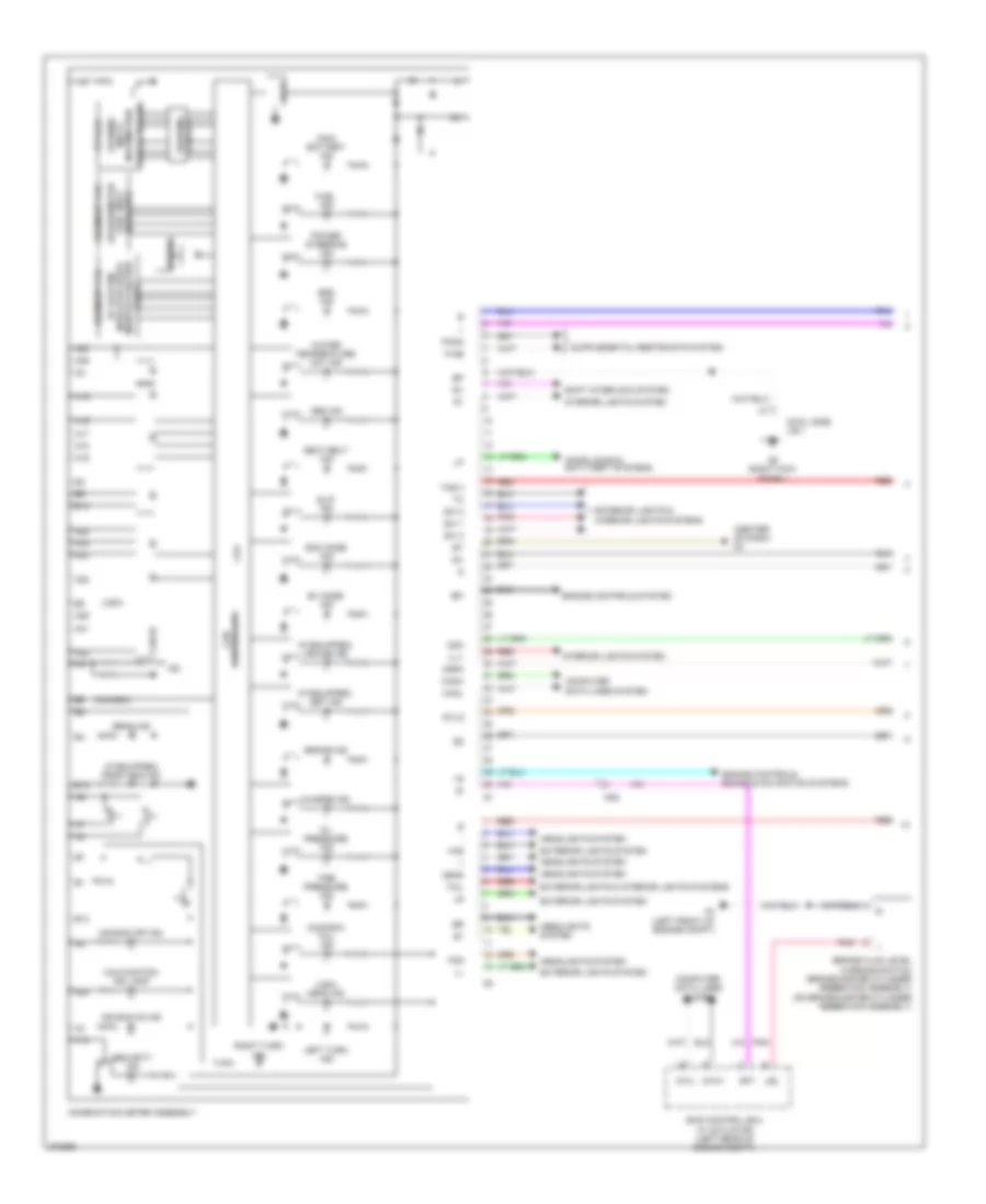
COMPUTER DATA LINES
Computer Data Lines Wiring Diagram for Toyota Prius C 2012
List of elements for Computer Data Lines Wiring Diagram for Toyota Prius C 2012:
- (left rear of engine compt) skid control ecm
- A/c amplifier assembly (lower center of hvac unit)
- A32
- A34
- A40
- A50
- A51
- Ag1
- Ag3
- Air bag sensor assembly
- B36
- Bat
- C13
- C2 (top front of engine)
- Ca1h
- Ca1l
- Ca2
- Ca2h
- Ca2l
- Ca3n
- Ca3p
- Canh
- Canl
- Cann
- Canp
- Certification ecu (w/ smart key system) (behind right side of dash)
- Combination meter assembly
- Cowl side j/b 1
- D22
- Dlc3 (data link connector 3) (under left side of dash)
- Ecm (center rear of engine compt)
- G18
- G34
- G5 (right kick panel)
- G54
- G57
- G58
- G71
- G78
- Hot at all times
- Instrument panel j/b (behind left end of dash)
- J/c a51 & g71 (left end of dash)
- J/c g72 (right side of dash)
- Lvl
- Main body ecu (behind left end of dash)
- Mg3
- My1
- Obd fuse 7.5a
- Occupant detection ecu (under front passenger's seat)
- Op4
- Pnk
- Power management control ecu (left end of dash)
- Power steering ecu (left side of dash)
- Radio & display receiver assembly (w/ display audio type)
- Red
- Right front seat inner belt assembly (left side of front passenger's seat)
- Sil
- Steering sensor (steering column)
- Tac
- Tach
- Transponder key ecu assembly (w/ engine immobiliser system & w/o smart key system) (center of dash)
COOLING FAN
Cooling Fan Wiring Diagram (1 of 2) for Toyota Prius C 2012
List of elements for Cooling Fan Wiring Diagram (1 of 2) for Toyota Prius C 2012:
- 5v +b
- 5v i/c
- A/c amplifier assembly (lower center of hvac unit)
- A/c control assembly
- A/c pressure sensor (right front of engine compt)
- A51
- Ag3
- C15
- Can controller
- Can i/f
- Canh
- Canl
- Combination meter assembly
- Computer data lines system
- Cowl side j/b 1
- Cpu
- Engine room r/b 2 (right rear of engine compt)
- G34
- G5 (right kick panel)
- G7 (center of dash)
- Gnd
- Hot w/ ig1 relay energized
- Htr-ig fuse 7.5a
- Ig+
- Instrument panel j/b (behind left end of dash)
- J/c a49 (left end of dash)
- J/c a50 (left end of dash)
- Lin 1
- Pre
- Ptc htr relay 1
- Ptc htr relay 2
- Ptc htr relay 3
- Ptc1
- Ptc2
- Ptc3
- Quick heater assembly (lower right side of dash)
- Red
- S5-3
- Sg-2
Cooling Fan Wiring Diagram (2 of 2) for Toyota Prius C 2012
List of elements for Cooling Fan Wiring Diagram (2 of 2) for Toyota Prius C 2012:
- +b1
- A3 (right side of engine compt)
- A40
- A52
- Ag2
- B14
- C10
- C2 (top front of engine)
- C36
- Canh
- Canl
- Computer data lines system
- Cooling fan ecu (on cooling fan motor)
- Cooling fan motor (behind radiator)
- Crank position sensor
- E 1
- Ecm (engine control module) (center rear of engine compt)
- Ecu-b 2 fuse 7.5a
- Efi engine coolant temperature sensor (rear of cylinder head)
- Efi main fuse 20a
- Efi main relay
- Engine room j/b 2 (right rear of engine compt)
- Engine room r/b 2 (right rear of engine compt)
- Ethw
- Fan fuse 30a
- Fan relay
- Hot at all times
- Hot w/ ig2 relay energized
- Instrument panel j/b (behind left end of dash)
- Meter fuse 7.5a
- Ne+
- Ne-
- Ptc htr 1 fuse 30a
- Ptc htr 2 fuse 30a
- Ptc htr 3 fuse 30a
- Red
- Rfc
- Thw
CRUISE CONTROL
Cruise Control Wiring Diagram (1 of 2) for Toyota Prius C 2012
List of elements for Cruise Control Wiring Diagram (1 of 2) for Toyota Prius C 2012:
- A1 (left rear of engine compt)
- A3 (right side of engine compt)
- A40
- Abs 2 fuse 10a
- Ag2
- Am1
- Batt
- Brake pedal stroke sensor (above brake pedal)
- C10
- C2 (top front of engine)
- Ca2h
- Ca2l
- Canh
- Canl
- Computer data lines system
- Ecm (engine control module) (center rear of engine compt)
- Efi main fuse 20a
- Efi main relay
- Engine room j/b 2 (right rear of engine compt)
- Engine room r/b 2 (right rear of engine compt)
- Eta
- Fl+
- Fl-
- Fr+
- Fr-
- Ge01
- Hot at all times
- Left front speed sensor (left front wheel hub assembly)
- Left rear speed sensor (left rear wheel hub assembly)
- Mrel
- Nca
- Pnk
- Red
- Right front speed sensor (right front wheel hub assembly)
- Right rear speed sensor (right rear wheel hub assembly)
- Rl+
- Rl-
- Rr+
- Rr-
- Skg
- Skid control ecu w/ actuator (left rear of engine compt)
- Sks
- Sks1
- Sks2
- Sp1
- Throttle body assembly (left side of engine)
- Vcsk
- Vcta
- Vta
- Vta1
- Vta2
- Wm1
- Xm1
Cruise Control Wiring Diagram (2 of 2) for Toyota Prius C 2012
List of elements for Cruise Control Wiring Diagram (2 of 2) for Toyota Prius C 2012:
- (above brake pedal, on bracket) stop light switch
- +res
- -set
- 5v ic
- A37
- A39
- A4 (left front of engine compt)
- Accelerator pedal sensor (on accelerator pedal assembly)
- Ag2
- Am2 fuse 7.5a
- Am22
- B15
- Buzzer
- C12
- Ca3n
- Ca3p
- Can controller
- Can i/f
- Cancel
- Canh
- Canl
- Ccs
- Combination meter assembly
- Computer data lines system
- Cpu
- Cruise control main switch (if equipped)
- Cruise ind
- Engine room r/b 2 (right rear of engine compt)
- Ep1
- Ep2
- G4 (left side of dash)
- G57
- G58
- G7 (center of dash)
- Gnd
- Hot at all times
- Hot in on or start
- I/f
- Ig 2 fuse 10a
- Ig+
- Ig2
- Instrument panel j/b (behind left end of dash)
- J/b a49 (left end of dash)
- J/c a50 (left end of dash)
- Meter fuse 7.5a
- On- off
- Pnk
- Power management control ecu (left end of dash)
- Red
- Set ind
- Spdi
- Spiral cable sub assembly w/ sensor (on steering column)
- St1-
- Stop fuse 7.5a
- Stp
- Vcp1
- Vcp2
- Vpa1
- Vpa2
- W/ smart key system
DEFOGGERS
Defoggers Wiring Diagram for Toyota Prius C 2012
List of elements for Defoggers Wiring Diagram for Toyota Prius C 2012:
- (behind left end of dash)
- A/c amplifier assembly (lower center of hvac unit)
- A/c control assembly
- A3 (right side of engine compt)
- A51
- Ag1
- Ag3
- Am2
- C27
- Condensor
- Cowl side j/b 1
- Cowl side j/b 2
- Def fuse 30a
- Def relay
- Ecu-ig 1 fuse 5a
- Engine room r/b 2 (right rear of engine c0mpt)
- G34
- G5 (right kick panel)
- G6 (left kick panel)
- Gnd
- Hg1
- Hot at all times
- Hot w/ ig1 1 relay energized
- Htr-ig fuse 7.5a
- Ig+
- Instrument panel j/b
- J/c a48 (left end of dash)
- Jg1
- Left outer rear view mirror assembly (w/ mirror heater)
- Lin1
- Mir htr fuse 10a
- Mirror heater
- Radio setting condenser (left "c" pillar)
- Rdfg
- Rear window defogger (back door glass)
- Rear window defogger switch
- Right outer rear view mirror assembly (w/ mirror heater)
- Sm1
- W/ mirror heater
- W/o mirror heater
ELECTRONIC POWER STEERING
Electronic Power Steering Wiring Diagram for Toyota Prius C 2012
List of elements for Electronic Power Steering Wiring Diagram for Toyota Prius C 2012:
- 5v ic
- A2 (left end of dash)
- A33
- A52
- A54
- Ag2
- Bat
- Buzzer
- Can controller
- Can i/f
- Canh
- Canl
- Combination meter assembly
- Computer data lines system
- Cowl side j/b 1
- Cpu
- Dome fuse 15a
- Ecu-ig 1 fuse 5a
- Ecu-ig 2 fuse 5a
- Engine room r/b (left side of engine compt)
- Engine room r/b 2 (right rear of engine compt)
- Eps fuse 50a
- Ess
- G5 (right kick) panel)
- G7 (center of dash)
- G73
- Hot at all times
- Hot in on or start
- Hot w/ ig1 1 relay energized
- I/f
- Ig+
- Instrument panel j/b (behind left end of dash)
- Junction connector g73 & g74 (left side g74 of dash)
- Meter fuse 7.5a
- Pgnd
- Pig
- Pnk
- Power steering ecu (left side of dash)
- Power steering ind
- Power steering motor
- Power steering motor (integral to power steering ecu assembly)
- Power steering torque sensor (integral to power steering ecu assembly)
- Red
- Steering sensor (steering column)
- Torque sensor
- Trq1
- Trq2
- Trqg
- Trqv
ENGINE PERFORMANCE
1.5L
1.5L, Engine Controls Wiring Diagram (1 of 6) for Toyota Prius C 2012
List of elements for 1.5L, Engine Controls Wiring Diagram (1 of 6) for Toyota Prius C 2012:
- +b1
- +b2
- A3 (right side of engine compt)
- A4 (left front of engine compt)
- A40
- Ag2
- Batt
- C/ opn relay
- C1 (left rear of engine)
- Ca2
- Canh
- Canl
- Cann
- Canp
- Computer data line system
- Computer data lines system
- Cooling fans system
- Efi main fuse 20a
- Efi main relay
- Egr valve assembly (top right side of engine)
- Egr1
- Egr2
- Egr3
- Egr4
- Eng
- Eng w/ pmp relay
- Engine control module (ecm) (center rear of engine compt)
- Engine room j/b 2 (right rear of engine compt)
- Engine room r/b 2 (left side of engine compt)
- Engine water pump assembly
- Eppm
- Etcs fuse 10a
- Fuse 30a
- Hot at all times
- Hot in on or start
- Igsw
- J/c a50 (left end of dash)
- Meter fuse 7.5a
- Mpmp
- Mrel
- Nwp
- Pgnd
- Pnk
- Ppmp
- Red
- Ref
- Swp
- Tach
- Vcpp
- Vpmp
- W/ pmp
- Wpi
- Wpo
1.5L, Engine Controls Wiring Diagram (2 of 6) for Toyota Prius C 2012
List of elements for 1.5L, Engine Controls Wiring Diagram (2 of 6) for Toyota Prius C 2012:
- (left end of dash) j/c a49
- (left rear of engine)
- (near fuel tank) canister pump module
- (top front of engine)
- +bm
- 1gn fuse 15a
- Am2
- C1 (left rear of engine)
- C10
- C2 (top front of engine)
- Ca2
- Canister pressureure sensor
- E01
- E02
- E04
- Efi fuse 2 10a
- Egr1
- Egr2
- Egr3
- Egr4
- Engine control module (ecm) (center rear of engine compt)
- Engine room r/b 2 (left side of engine compt)
- Fuel suction tube assembly w/ pump & gage
- Ge01
- Ha1a
- Hot in on or start
- Ht1b
- Ig2 fuse 2 10a
- Igt1
- Igt2
- Igt3
- Igt4
- Leak dete- ction pump
- Me01
- Pnk
- Pump
- Red
- Vent valve
1.5L, Engine Controls Wiring Diagram (3 of 6) for Toyota Prius C 2012
List of elements for 1.5L, Engine Controls Wiring Diagram (3 of 6) for Toyota Prius C 2012:
- (center rear of engine compt) engine control module (ecm)
- (left side of engine) throttle body assembly w/ motor
- (top of engine) fuel injector assembly 1
- (top of engine) fuel injector assembly 2
- A37
- B15
- C10
- C12
- C2 (top of front engine)
- Can controller
- Can i/f
- Ce1
- Combination meter assembly
- Computer data lines system
- Cpu
- Eco mode ind
- Ev mode ind
- G7 (center of dash)
- Hot at all times
- Ind lamp malfunction
- Instrument panel j/b (behind left end of dash)
- Knock control sensor (bank 1) (left side of engine)
- Pnk
- Purge vsv (left side of engine)
- Red
- Stop fuse 7.5a
- Vta
- Vta2
1.5L, Engine Controls Wiring Diagram (4 of 6) for Toyota Prius C 2012
List of elements for 1.5L, Engine Controls Wiring Diagram (4 of 6) for Toyota Prius C 2012:
- (left end of dash) power management control ecu
- (top of engine)
- (top of engine) fuel injector assembly 3
- (top of engine) fuel injector assembly 4
- +b1
- A39
- A4 (left front of engine compt)
- C1 (left rear of engine)
- Ca1h
- Ca1l
- Computer data lines system
- Db1
- Db2
- Ep1
- Ep2
- G57
- G58
- Gnd
- Igf
- Ignition coil assembly 1
- Ignition coil assembly 2
- Ignition coil assembly 3
- Ignition coil assembly 4
- Igt1
- Igt2
- Igt3
- Igt4
- J/c a50 (left end of dash)
- Pnb
- Pnk
- Red
- Spdi
- St1-
- Stop light switch (above brake pedal, on bracket)
- Stp
- Vcp1
- Vcp2
- Vpa1
- Vpa2
1.5L, Engine Controls Wiring Diagram (5 of 6) for Toyota Prius C 2012
List of elements for 1.5L, Engine Controls Wiring Diagram (5 of 6) for Toyota Prius C 2012:
- (left end of dash) j/c a48
- Accelerator pedal sensor (on accelerator pedal assembly)
- C2 (top front of engine)
- Ca1
- E2g
- Ep1
- Ep2
- Intake mass air flow meter sub-assembly (left side of engine)
- N r
- Pnk
- R n
- Red
- Shift lever switch
- Tha
- Vcp1
- Vcp2
- Vpa1
- Vpa2
1.5L, Engine Controls Wiring Diagram (6 of 6) for Toyota Prius C 2012
List of elements for 1.5L, Engine Controls Wiring Diagram (6 of 6) for Toyota Prius C 2012:
- (front of cylinder head) camshaft timing oil control valve assembly
- (left side of engine) efi vacuum sensor assembly
- (lower left front of engine) crank position sensor
- (rear of cylinder head) efi engine coolant temperature sensor
- A1a+
- A1a-
- Air fuel ratio sensor (bank 1 sensor 1) (top rear of engine)
- C10
- C2 (top front of engine)
- Cam position sensor
- E2g
- Eknk
- Engine control module (ecm) (center rear of engine compt)
- Epim
- Eta
- Etha
- Ethw
- Ex1b
- Ha1a
- Ht1b
- Igf1
- Knk1
- Nca
- Ne+
- Ne-
- Oc1+
- Oc1-
- Ox1b
- Oxygen sensor (bank 1 sensor 2) (right rear of engine)
- Pim
- Pnk
- Prg
- Red
- Tha
- Thw
- Vcpm
- Vctc
- Vta1
- Vta2
- Vv1+
- Vv1-
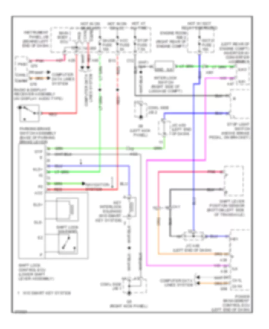
1.5L, Hybrid System Wiring Diagram (1 of 6) for Toyota Prius C 2012
List of elements for 1.5L, Hybrid System Wiring Diagram (1 of 6) for Toyota Prius C 2012:
- (right side of engine compt) a3
- +b2
- 5v +b
- 5v ic
- A37
- A38
- Ag2
- Air conditioning system
- Am1
- B14
- B15
- Batt fan fuse 10a
- Buzzer
- C12
- C36
- Ca1
- Can controller
- Can i/f
- Charge ind
- Clk
- Combination meter assembly
- Computer data lines system
- Cpu
- Drawing circuit
- Eco mode ind
- Ecu-b 2 fuse 7.5a
- Engine room r/b 2 (right rear of engine compt)
- Eti
- Ev mode ind
- Exterior lights system
- G7 (center of dash)
- Gmt
- Gmtg
- Hot at all times
- Hot in on or start
- Hv system indicator drive monitor odo/trip clock
- I/f
- Ig2
- Igct 2 fuse 10a
- Igct 3 fuse 10a
- Igct 4 fuse 10a
- Igct relay
- Ilk
- Instrument panel j/b (behind left end of dash)
- Ite
- Iwp
- Main igct fuse 30a
- Meter fuse 7.5a
- Mmt
- Mmtg
- Niwp
- Nodd
- Opening multi information touch tracer
- Pcu fuse 10a
- Pnk
- Power management control ecu (left end of dash)
- Red
- Segment vfd
- Si0
- Skid control ecu (left rear of engine compt)
- Sp1
- Speedometer fuel shift indicator
- Stb
- Stop fuse 7.5a
- Tft lcd
- Vlo
1.5L, Hybrid System Wiring Diagram (2 of 6) for Toyota Prius C 2012
List of elements for 1.5L, Hybrid System Wiring Diagram (2 of 6) for Toyota Prius C 2012:
- (behind right side of dash) certification ecu
- (w/ smart key system) power switch
- +bwp
- A4 (left front of engine compt)
- Agnd
- Canh
- Canl
- Code
- Computer data lines system
- Cowl side j/b 1
- Engine room r/b 2 (right rear of engine compt)
- G5 (right kick panel)
- G54
- G55
- Gnd
- Hot in on or start
- Hv battery thermometer (right rear of luggage compt)
- Ig2 2 fuse 10a
- Inverter water pump motor (left front of engine compt)
- J/c a48 (left end of dash)
- J/c a49 (left end of dash)
- Mg4
- Nwp
- Pnk
- Red
- Ss1
- Ss2
- Swil
- Swp
- Transponder key coil
- Txct
- Vc5
1.5L, Hybrid System Wiring Diagram (3 of 6) for Toyota Prius C 2012
List of elements for 1.5L, Hybrid System Wiring Diagram (3 of 6) for Toyota Prius C 2012:
- +b2
- A4 (left front of engine compt)
- A47
- Abfs
- Air conditioning system
- Am1
- Am22 batt
- Bth+
- Bth-
- Clk+
- Clk-
- Computer data lines system
- Cowl side j/b 2
- Drn1
- Drn2
- Drn3
- Drn4
- Drn5
- Drn8
- E01
- Ethb
- Evsw
- G4 (left side of dash)
- G57
- G6 (left kick panel)
- G74
- Gnd
- Gnd1
- Gnd2
- Hsdn
- Htm+
- Htm-
- Idh
- Igct
- Ilk
- Ilki
- Ilko
- Inter lock switch (right side of luggage compt)
- Inverter w/ converter (left rear of engine compt)
- J/c g73 & g74 (left side of dash) g73
- Mth+
- Mth-
- Nodd
- Pnk
- Power management control ecu (left end of dash)
- Red
- Req+
- Req-
- Shift lock control ecu
- Smrb
- Smrg
- Smrp
- Spdi
- Ssw1
- Thb
- Vlo
- W/ smart key system
- W/o smart key system
1.5L, Hybrid System Wiring Diagram (4 of 6) for Toyota Prius C 2012
List of elements for 1.5L, Hybrid System Wiring Diagram (4 of 6) for Toyota Prius C 2012:
- (left rear of engine compt) inverter w/ converter
- A4 (left front of engine compt)
- Acc
- Acpb
- Acpe
- Air conditioning system
- Amd
- C24
- C25
- C26
- C28
- Ca1
- Ca2
- Cbi
- Cei
- Cowl side j/b 1
- Dc/dc fuse 100a
- Drn6
- Engine room j/b (left side of engine compt)
- Engine room r/b 2 (right rear of engine compt)
- Ev switch
- G5 (right kick panel)
- Gcs
- Gcsg
- Gmt
- Gmtg
- Gnd
- Grf
- Grfg
- Gsn
- Gsng
- Hot at all times
- Hot in on or start
- Hybrid vehicle transaxle assembly
- Ign fuse 15a
- J/c a50 (left end of dash)
- Mcs
- Mcsg
- Mmt
- Mmtg
- Mrf
- Mrfg
- Msn
- Msng
- Nca
- Out
- Pattern select switch assembly
- Pnk
- Red
- Skid control ecu (left rear of engine compt)
- Stop light switch (above brake pedal, on bracket)
- Stp
- Stp2
- Stpo
1.5L, Hybrid System Wiring Diagram (5 of 6) for Toyota Prius C 2012
List of elements for 1.5L, Hybrid System Wiring Diagram (5 of 6) for Toyota Prius C 2012:
- (left "c" pillar) j/c m46
- (left end of dash) j/c a49
- (w/o smart key system) ignition or starter switch assembly
- Ag2
- Am1
- Am2
- Battery cooling blower assembly (left end of hybrid battery assembly)
- Battery voltage sensor
- Bth+
- Bth-
- Busbar
- Busbar module
- Cowl side j/b 2
- Current sensor
- Engine room r/b 2 (right rear of engine compt)
- Fp0
- G6 (left kick panel)
- Gb0
- Gb0 z9
- Gb1
- Gb2
- Gc0
- Gib
- Gnd
- Gnd0
- Hot w/ ig2 relay energized
- Hv battery junction block (right side of luggage compt)
- Hybrid junction block assembly (left side of hybrid battery assembly)
- Hybrid vehicle battery
- Ig0
- Ig2
- Ig2 2 fuse 10a
- Igct
- M39
- M40
- Main relay 1
- Main relay 2
- Mg4
- Nca
- Pnk
- Precharge relay
- Red
- Resistor
- Service plug
- Si0
- St2
- Tb0
- Tb1
- Tb2
- Tc0
- Thermistor
- Vb1
- Vb10
- Vb2
- Vb3
- Vb4
- Vb5
- Vb6
- Vb7
- Vb8
- Vb9
- Vib
1.5L, Hybrid System Wiring Diagram (6 of 6) for Toyota Prius C 2012
List of elements for 1.5L, Hybrid System Wiring Diagram (6 of 6) for Toyota Prius C 2012:
- (center rear of engine compt) engine control module (ecm)
- (left rear of engine) c1
- +b1
- A39
- A40
- Accd
- Accelerator pedal sensor (on accelerator pedal assembly)
- Ag2
- Am2 fuse 7.5a
- Am21
- Anti-theft system
- B29
- C10
- C36
- Ca1
- Ca1h
- Ca1l
- Ca3n
- Ca3p
- Canh
- Canl
- Ccs
- Clk+
- Clk-
- Computer data lines system
- Cowl side j/b 2
- Cruise control system
- Db1
- Db2
- Door locks system
- E02
- Ecu-b 2 fuse 7.5a
- Engine room r/b 2 (right rear of engine compt)
- Ep1
- Ep2
- Exterior light system
- G2o
- G58
- G6 (left kick panel)
- Gnd
- Hot at all times
- Hsdn
- Htm+
- Htm-
- Ig1d
- Ig2
- Ig2d
- Igf
- Igf1
- Ignition coil +b assembly (top of engine)
- Ignition coil assembly (top of engine)
- Ignition coil assembly 4 (top of engine)
- Igt1
- Igt2
- Igt3
- Igt4
- Imi
- Imo
- Instrument panel j/b (behind left end of dash)
- Lin2
- Mrel
- Mth+
- Mth-
- N r
- Pnb
- Pnk
- Power distribution system
- Power management control ecu (left end of dash)
- R n
- Red
- Req+
- Req-
- Shift lever position sensor (bottom left side of transaxle)
- Slp
- Slr+
- Ssw2
- St1-
- St2
- Stp
- Vcp1
- Vcp2
- Vpa1
- Vpa2
- W/ smart key system
- W/o smart key system
EXTERIOR LIGHTS
Backup Lamps Wiring Diagram for Toyota Prius C 2012
List of elements for Backup Lamps Wiring Diagram for Toyota Prius C 2012:
- (left end of dash) j/c a48
- A3 (right side of engine compt)
- A38
- A39
- B/kup lp relay
- Backup light
- C14
- C33
- Ca1
- Ca1h
- Ca1l
- Computer data lines system
- D28
- D29
- Engine room r/b 2 (right rear of engine compt)
- G58
- Gauge fuse 10a
- Hot at all times
- Hot in on or start
- Igct 2 fuse 10a
- Igct main fuse 30a
- Igct relay
- Instrument panel j/b (behind left end of dash)
- J/c a48 (left end of dash)
- Left rear combination light assembly
- Mrel
- Pnk
- Power management control module ecu (left end of dash)
- Red
- Right rear combination light assembly
- Shift lever position sensor (bottom left side of transaxle)
Exterior Lamps Wiring Diagram (1 of 2) for Toyota Prius C 2012
List of elements for Exterior Lamps Wiring Diagram (1 of 2) for Toyota Prius C 2012:
- A15
- A16
- A3 (right side of engine compt)
- A35
- A40
- A44
- A5 (left side of engine compt)
- A54
- A56
- Acc
- Acc fuse 5a
- Backup
- Backup lamp circuit
- Becu
- C21
- Canh
- Canl
- Center stop light set
- Computer data lines system
- Cowl side j/b 2
- D10
- Ecu-b 1 fuse 7.5a
- Ecu-ig fuse 5a
- Engine room r/b 2 (right rear of engine compt)
- G59
- G6 (left kick panel)
- Gnd1
- Hot at all times
- Hot in on or acc
- Hot in on or start
- Instrument panel j/b (behind left end of dash)
- Interior lights system
- J/c a50 (left end of dash)
- J/c g73 (left side of dash)
- J/c m46 (left "c" pillar)
- Left headlight assembly
- Left license plate light assembly
- Left rear combination light assembly
- Main body ecu
- Marker side
- Marker tail/side
- Panel fuse 5a
- Parking
- Radio setting condenser (left "c" pillar)
- Red
- Right headlight assembly
- Right license plate light assembly
- Right rear combination light assembly
- Side marker
- Sm1
- St1
- Tail
- Tail fuse 10a
- Tail relay
- Tail/side marker
- Tail/stop
- Trly
- Turn
Exterior Lamps Wiring Diagram (2 of 2) for Toyota Prius C 2012
List of elements for Exterior Lamps Wiring Diagram (2 of 2) for Toyota Prius C 2012:
- (behind left end of dash) instrument panel j/b
- A3 (right side of engine compt)
- A39
- A4 (left front of engine compt)
- A5 (left side of engine compt)
- Ag2
- Auto
- B24
- B25
- B38
- B39
- C12
- C19
- C25
- C28
- C38
- Can
- Can i/f
- Canh
- Canl
- Combination meter assembly
- Computer data lines system
- Cowl
- Cowl side j/b 1
- Cowl side j/b 2
- Cpu
- D18
- Dc/cd fuse 100a
- Engine room j/b (left side of engine compt)
- Engine room r/b 2 (right rear of engine compt)
- G5 (right kick panel)
- G6 (left kick panel)
- G7 (center of dash)
- Gnd
- Haz
- Hazard warning signal switch assembly
- Head
- Headlight dimmer switch assembly
- Hg1
- Hot at all times
- Hot in on or start
- I/f
- Ig+
- Ig2 2 fuse 10a
- Instrument panel j/b (behind left end of dash)
- J/c a49 (left end of dash)
- J/c a50 (left end of dash)
- Jg1
- Left
- Left front turn signal light assembly
- Left outer rear view mirror assembly
- Left turn
- Light control switch
- Meter fuse 7.5a
- Off
- Out
- Pnk
- Power management control ecu (left end of dash)
- Red
- Right
- Right front turn signal light assembly
- Right outer rear view mirror assembly
- Right turn
- Side j/b 1
- St1-
- Stop fuse 7.5a
- Stop light switch (above brake pedal, on bracket)
- Stp
- Tail
- Turn
- Turn signal switch
GROUND DISTRIBUTION
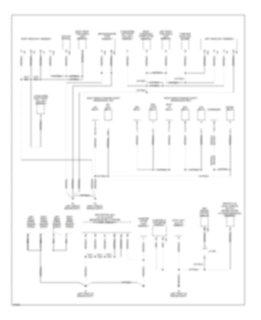
Ground Distribution Wiring Diagram (1 of 4) for Toyota Prius C 2012
List of elements for Ground Distribution Wiring Diagram (1 of 4) for Toyota Prius C 2012:
- (if equipped) left front fog light assembly
- (if equipped) right front fog light assembly
- (right rear of engine compt) engine room j/b 2
- (right rear of engine compt) engine room r/b 2
- A1 (left front of engine compt)
- A15
- A16
- A3 (right side of engine compt)
- A4 (left front of engine compt)
- A40
- A45
- A46
- A47
- A5 (left side of engine compt)
- A52
- Bkup lp relay
- Brake booster pump assembly
- Brake fluid level warning switch (brake master cylinder reservoir assembly)
- Condensor
- Cooling fan ecu
- Def relay
- Dim/drl relay
- Ecm (engine control module)
- Efi main relay
- Eng w/pmp relay
- Fan relay
- Front windshield wiper motor assembly
- Ig2 relay
- Igct relay
- Inverter w/ converter assembly
- Inverter water pump assembly
- J/c a50
- Left front speed sensor shield
- Left front turn signal light assembly
- Left headlight assembly
- Left rear speed sensor shield
- Nca
- Right front speed sensor shield
- Right front turn signal light assembly
- Right headlight assembly
- Right rear speed sensor shield
- Skid control ecu (w/ actuator) (brake booster w/ master cylinder assembly)
- Stop light switch assembly
- Wireless door lock buzzer
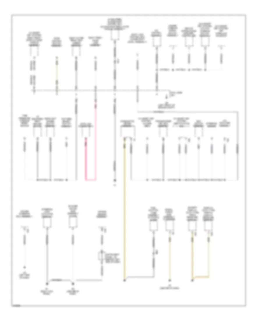
Ground Distribution Wiring Diagram (2 of 4) for Toyota Prius C 2012
List of elements for Ground Distribution Wiring Diagram (2 of 4) for Toyota Prius C 2012:
- (display auto type) radio & display receiver assembly
- (except display auto type) radio receiver assembly
- (if equipped) seat heater switch
- (if equipped) sliding roof control ecu (sliding roof regulator handle assembly)
- (w/ smart key system)
- (w/ smart key system) right front door outside handle assembly
- (w/o smart key system) key interlock solenoid
- (w/o smart key system) un-lock warning switch assembly
- A/c amplifier assembly
- A/c control assembly
- A2 (left end of dash)
- A33
- Air bag sensor assembly
- Blower motor sub assembly w/ fan
- Certification ecu
- Combination meter assembly
- Cowl side j/b 1
- Data link connector 3
- Door control switch assembly
- Eco switch assembly
- Fuel suction tube assembly w/ pump & gage
- G1 (right kick panel)
- G18
- G3 (center of dash)
- G34
- G37
- G5 (left front of engine compt)
- G55
- G7 (center of dash)
- G76
- Hazard warning signal switch assembly
- Headlight dimmer switch assembly
- Id code box
- Instrument panel j/b (behind left end of dash)
- Mg2
- Pattern select switch assembly
- Pnk
- Power steering ecu assembly
- Qg1
- Right front door lock assembly
- Right outer rear view mirror assembly
- Shift lock control ecu (lower shift level assembly)
- Spiral cable sub- assembly w/ sensor
- Steering lock actuator assembly
- Steering sensor
- Tire pressure warning reset switch
- Transponder key ecu assembly
- Vehicle approaching speaker controller
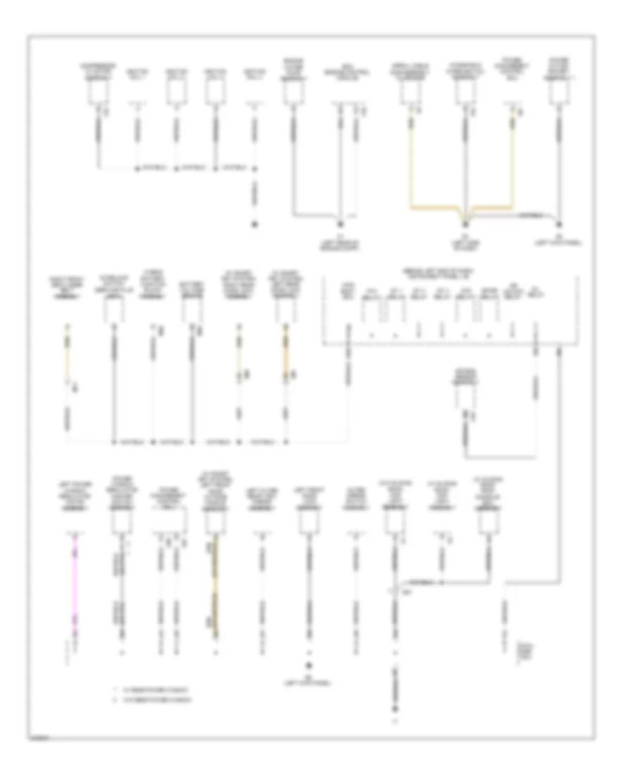
Ground Distribution Wiring Diagram (3 of 4) for Toyota Prius C 2012
List of elements for Ground Distribution Wiring Diagram (3 of 4) for Toyota Prius C 2012:
- (behind left end of dash) instrument panel j/b
- (service plug grip)
- (w/ sliding roof) map light assembly
- (w/ sliding roof) roof console box assembly
- (w/ smart key system) left front door outside handle assembly
- (w/ smart key system) left rear door lock assembly
- (w/ smart key system) right rear door lock assembly
- (w/o sliding roof) map light assembly
- Acc relay
- Air bag sensor assembly
- Battery voltage sensor
- Bk/dr relay
- C1 (left rear of engine compt)
- C10
- C22
- Compressor w/ motor assembly
- Cowl side j/b 2
- D/l relay
- D26
- Dr unlock relay
- Ecm (engine control module)
- Engine water pump assembly
- G12
- G18
- G2 (left kick panel)
- G4 (left side of dash)
- G57
- G58
- G6 (left kick panel)
- Hybrid battery junction block assembly
- Ig1 1 relay
- Ig1 2 relay
- Ig1 3 relay
- Ignition coil 1
- Ignition coil 2
- Ignition coil 3
- Ignition coil 4
- Interlock switch
- Km1
- Left front door lock assembly
- Left outer rear view mirror assembly
- Left power window regulator motor assembly
- Lm1
- M39
- M40
- Main body ecu
- My1
- Outer mirror switch assembly
- P/w relay
- Power management control ecu
- Power outlet socket assembly 1
- Power window regulator master switch assembly
- Qg1
- Right front seat inner belt assembly
- Spiral cable sub-assembly w/ sensor
- W/ rear power window
- W/o rear power window
- Windshield wiper switch assembly
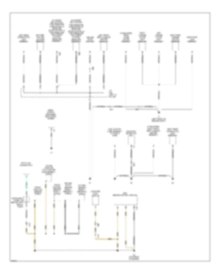
Ground Distribution Wiring Diagram (4 of 4) for Toyota Prius C 2012
List of elements for Ground Distribution Wiring Diagram (4 of 4) for Toyota Prius C 2012:
- (if equipped) rear wiper motor assembly
- (if equipped) right front seat cushion heater assembly
- (w/ smart key system) tire pressure warning ecu & receiver (door control & tire pressure monitoring system receiver assembly)
- (w/o smart key system)
- A34
- Air fuel ratio sensor (bank 1 sensor 1) shield
- Am2
- Back door lock assembly
- Back door opener switch assembly
- Battery cooling blower assembly
- C10
- C13
- C2 (top front of engine)
- Ca1
- Ca2
- Canister pump module
- Center stop light set
- Crank position sensor shield
- Data link connector 3
- Ecm (engine control module)
- Fuel suction tube assembly w/ pump & gage
- Instrument panel j/b (behind left end of dash)
- Intake mass air flow master sub-assembly shield
- J/c m46 (left "c" pillar)
- Knock control sensor (bank 1) shield
- Left front seat cushion heater assembly
- Left license plate light assembly
- Left rear combination light assembly
- M17
- M20
- My1
- Nca
- Occupant detection ecu
- Oxygen sensor (bank 1 sensor 2) shield
- Rear window defogger (back door glass)
- Right license plate light assembly
- Right rear combination light assembly
- Sm1
- St1
- T1 (left front of engine compt)
- Tire pressure warning ecu & receiver (door control & tire pressure monitoring system receiver assembly)
HEADLIGHTS
Headlights Wiring Diagram (1 of 2) for Toyota Prius C 2012
List of elements for Headlights Wiring Diagram (1 of 2) for Toyota Prius C 2012:
- (usa)
- A28
- A3 (right side of engine compt)
- A40
- A5 (left side of engine compt)
- A54
- Acc
- Acc fuse 5a
- Auto
- B23
- Becu
- C18
- C21
- C22
- C35
- Canh
- Canl
- Computer data lines system
- Cowl side j/b 1
- Cowl side j/b 2
- Dc/dc fuse 100a
- Dim
- Dimmer switch
- Drl
- Drl off
- Drlc
- Ecu- ig 1 fuse 5a
- Engine room j/b (left side of engine compt)
- Ffgo
- Ffog
- Flash
- Fog fr fuse 15a
- Fog fr relay
- Fog light switch
- G5 (right kick panel)
- G6 (left kick panel)
- Gnd
- Head
- Headlight dimmer switch assembly
- High
- Hot at all times
- Hot in on or acc
- Hot in on or start
- Hrly
- Instrument panel j/b (behind left end of dash)
- J/c g73 (left side of dash)
- Left front fog light assembly
- Light control switch
- Low
- Main body ecu (behind left end of dash)
- Off
- Parking brake switch assembly (base of parking brake lever)
- Pkb
- Pnk
- Red
- Right front fog light assembly
- Tail
- Tail fuse 10a
- Tail relay
- Trly
Headlights Wiring Diagram (2 of 2) for Toyota Prius C 2012
List of elements for Headlights Wiring Diagram (2 of 2) for Toyota Prius C 2012:
- (+)
- (-)
- (right side of engine compt)
- (usa)
- 5v ic
- 5v+b
- A3 (right side of engine compt)
- A5 (left side of engine compt)
- Ag2
- Ag4
- B14
- B18
- Beam ind
- C36
- Combination meter assembly
- Cpu
- Dim/drl relay
- Drls
- Ecu-b 2 fuse 7.5a
- Ecu-b1 fuse 7.5a
- Engine room r/b 2 (right rear of engine compt)
- Front fog ind
- G7 (center of dash)
- H-lp lh-hi fuse 10a
- H-lp lh-lo fuse 10a
- H-lp main fuse 40a
- H-lp relay
- H-lp rh-hi fuse 10a
- H-lp rh-lo fuse 10a
- Head ind (usa)
- Hlol
- Hlor
- Hot at all times
- Hot in on or start
- Instrument panel j/b (behind left end of dash)
- Left headlight assembly
- Meter fuse 7.5a
- Pnk
- Red
- Right headlight assembly
- Usa
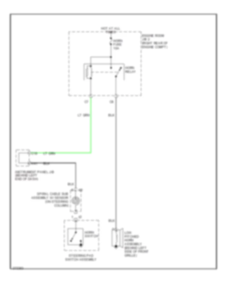
HORN
Horn Wiring Diagram for Toyota Prius C 2012
List of elements for Horn Wiring Diagram for Toyota Prius C 2012:
- A41
- C19
- Engine room j/b 2 (right rear of engine compt)
- Horn fuse 10a
- Horn relay
- Horn switch
- Hot at all times
- Instrument panel j/b (behind left end of dash)
- Low pitched horn assembly (behind left side of front grille)
- Spiral cable sub assembly w/ sensor (on steering column)
- Steering pad switch assembly
INSTRUMENT CLUSTER
Instrument Cluster Wiring Diagram (1 of 3) for Toyota Prius C 2012
List of elements for Instrument Cluster Wiring Diagram (1 of 3) for Toyota Prius C 2012:
- (canada)
- (canada) tail ind
- (center of dash) g7
- (if equipped) cruise ind
- (if equipped) front fog ind
- (if equipped) set ind
- (usa)
- (usa) head ind
- 5v ic
- A13
- A15
- A16
- A17
- A18
- A19
- A20
- A21
- A22
- A24
- A28
- A29
- A30
- A31
- A32
- A34
- A36
- A39
- A4 (left front of engine compt)
- A40
- Abs ind
- Ag2
- Air bag off ind
- Air bag on ind
- B10
- B12
- B13
- Beam ind
- Brake fluid level warning switch (brake master cylinder reservoir assembly) (on brake master cylinder reservoir assembly)
- Brake ind
- Buzzer
- Ca1h
- Ca1l
- Can i/f
- Canh
- Canl
- Charge ind
- Circuit drawing
- Combination meter assembly
- Computer data lines system
- Controller can
- Cowl side j/b 1
- Cpu
- Door locks & anti-theft systems
- Eco mode ind
- Efi
- Engine controls system
- Engine controls, sound & navigation systems
- Ev mode ind
- Exterior lights & interior lights systems
- Exterior lights system
- Fog
- Fuel ind
- G5 (right kick panel)
- Haz
- Head
- Headlights system
- Hv system indicator drive
- I/f
- Ig+
- Ig2
- Ill+
- Indicator fuel shift
- Information multi
- Interior lights system
- Lbl
- Left turn ind
- Main battery ind
- Malfunction ind lamp
- Monitor odo/trip clock
- Msfm
- Odo
- Oil pressure ind
- Opening
- P-ab
- Paon
- Pnk
- Power steering ind
- Red
- Right turn ind
- Seat belt ind
- Security ind
- Segment vfd
- Shift interlock system
- Skid control ecu w/ actuator (left rear of engine compt)
- Slip ind
- Sp1
- Speedometer
- Srs ind
- Stlg
- Sw 1
- Sw 2
- Sw 3
- Tail
- Tft lcd
- Tire pressure ind
- Tns 3
- Touch tracer
- Water temperature hot ind
Instrument Cluster Wiring Diagram (2 of 3) for Toyota Prius C 2012
List of elements for Instrument Cluster Wiring Diagram (2 of 3) for Toyota Prius C 2012:
- (left side of dash)
- A48
- Ag1
- Ag2
- B14
- C31
- C36
- Ca1
- Ce1
- Disp
- Display audio type
- Ecu-b fuse 7.5a
- Engine oil pressure switch (lower front of engine)
- Engine room r/b 2 (right rear of engine compt)
- Except display audio type
- G7 (center of dash)
- Haz fuse 10a
- Hot at all times
- Hot w/ ig2 relay energized
- Ig2 fuse 10a
- Instrument panel j/b (behind left end of dash)
- J/c a49 (left ent of dash)
- J/c g73
- Meter fuse 7.5a
- Micro computer
- Parking brake switch assembly (base of parking brake lever)
- Red
- Spiral cable sub-assembly w/ sensor
- Steering pad switch assembly
- Touch sensor
- Trip
Instrument Cluster Wiring Diagram (3 of 3) for Toyota Prius C 2012
List of elements for Instrument Cluster Wiring Diagram (3 of 3) for Toyota Prius C 2012:
- (center rear of engine compt) engine coolant temperature sensor
- (left side of dash)
- A28
- A40
- A54
- Acc
- Acc fuse 5a
- Ag4
- Back door lock assembly (center rear of luggage compt)
- Bcty
- Becy
- C21
- Canh
- Canl
- Computer data lines system
- Cowl side j/b 2
- D35
- D36
- Ecu-ig fuse 5a
- Flcy
- Frcy
- Fuel suction tube assembly w/ pump & gage
- G59
- G6 (left kick panel)
- G7 (center of dash)
- Gnd1
- Hot in on or acc
- Hot w/ ig1 relay energized
- Instrument panel j/b (behind left end of dash)
- J/c g73
- Lcty
- Left front door courtesy light switch assembly (left "b" pillar)
- Left rear door courtesy light switch assembly (left "c" pillar)
- Main body ecu
- Mg1
- Mg2
- Pkb
- Rcty
- Red
- Right front door courtesy light switch assembly (right "b" pillar)
- Right rear door courtesy light switch assembly (right "c" pillar)
- Sm1
- St1
- T1 (right side of luggage compt)
INTERIOR LIGHTS
Courtesy Lamps Wiring Diagram for Toyota Prius C 2012
List of elements for Courtesy Lamps Wiring Diagram for Toyota Prius C 2012:
- (left end of dash) j/c g73
- (left kick panel) g6
- (right kick panel) g5
- A40
- A54
- Acc
- Acc fuse 5a
- Act -
- Ag4
- Back door lock assembly
- Bctl
- Bcty
- Bcyl
- Becu
- C21
- Canh
- Canl
- Computer data lines system
- Cowl side j/b 1
- Cowl side j/b 2
- Cty
- D24
- D25
- D35
- D36
- Dome cut relay
- Dome fuse 15a
- Domr
- Ecu-b1 fuse 7.5a
- Ecu-ig1 fuse 5a
- Engine room r/b (right rear of engine compt)
- Flcy
- Frcy
- G59
- G6 (left kick panel)
- G6 (left kick panel) cowl side j/b 2
- Gnd1
- Hg1
- Hot at all times
- Hot in on or acc
- Hot w/ ig1 1 relay energized
- Ile
- Instrument panel j/b (behind left end of dash)
- Jg1
- Km1
- Lcty
- Left front door courtesy light switch assembly (left "b" pillar)
- Left front door lock assembly
- Left rear door courtesy light switch assembly (left "c" pillar)
- Left rear door lock assembly (w/ smart key system)
- Lm1
- Lsfl
- Lsfr
- Lsr
- Luggage compartment light assembly 1 (if equipped)
- Main body ecu
- Map light assembly
- Mg1
- Mg2
- Qg1
- Rcty
- Red
- Right front door courtesy light switch assembly (right "b" pillar)
- Right front door lock assembly
- Right rear door courtesy light switch assembly (right "c" pillar)
- Right rear door lock assembly (w/ smart key system)
- Sm1
- St1
- T1 (right side of luggage compt)
- Unlock detection
- W/ sliding roof
Instrument Illumination Wiring Diagram (1 of 2) for Toyota Prius C 2012
List of elements for Instrument Illumination Wiring Diagram (1 of 2) for Toyota Prius C 2012:
- (except display audio type) radio receiver assembly (display audio type) radio & display receiver assembly
- (left side of dash) j/c g73
- 21c
- A/c control assembly
- A35
- A40
- A54
- A56
- Acc
- Acc fuse 5a
- Auto
- Becu
- Canh
- Canl
- Computer data lines system
- Cowl side j/b 1
- Dc/dc fuse 100a
- Display audio type
- Eco switch assembly
- Ecu b1 fuse 7.5a
- Ecu ig1 fuse 5a
- Engine room j/b (left side of engine compt)
- Engine room r/b 2 (right rear of engine compt)
- Except display audio type
- G37
- G38
- G5 (right kick panel)
- G59
- G6 (left kick panel) cowl side j/b 2
- G7 (center of dash)
- G73
- G74
- G76
- G77
- Gnd
- Gnd1
- Hazard warning signal switch assembly
- Head
- Headlight dimmer switch assembly
- Hot at all times
- Hot in on or acc
- Hot w/ ig11 relay energized
- Ill+
- Ill-
- Instrument panel j/b (behind left end of dash)
- J/c g73 & g74 (left side of dash)
- Light control switch
- Main body ecu (behind left end of dash)
- Off
- Panel fuse 5a
- Pattern select switch assembly
- Pnk
- Red
- Seat heater switch (if equipped)
- Shift position indicator
- Spiral cable sub-assembly w/ sensor
- Steering pad switch assembly
- Tail
- Tail relay
- Trly
Instrument Illumination Wiring Diagram (2 of 2) for Toyota Prius C 2012
List of elements for Instrument Illumination Wiring Diagram (2 of 2) for Toyota Prius C 2012:
- 5v ic
- Ag2
- Agnd
- Can i/f
- Canh
- Canl
- Certification ecu (w/ smart key system) (behind right side of dash)
- Combination meter assembly
- Computer data lines system
- Controller can
- Cpu
- Engine room r/b 2 (right rear of engine compt)
- G5 (center of dash) cowl side j/b 1
- G54
- G55
- G7 (center of dash)
- Hot w/ ig2 relay energized
- I/f
- Ill+
- Light control rheostat
- Meter fuse 7.5a
- Pnk
- Power switch
- Red
- Sw1
- Sw2
- Sw3
- Swil
NAVIGATION
Navigation Wiring Diagram (1 of 3) for Toyota Prius C 2012
List of elements for Navigation Wiring Diagram (1 of 3) for Toyota Prius C 2012:
- A16
- A48
- A49
- Acc
- Adpg
- Ag2
- Agnd
- Alo
- Antenna
- Aro
- Asgn
- B13
- B14
- B15
- C31
- C38
- Ca1h
- Ca1l
- Can h
- Can l
- Computer data lines system
- Display audio type
- Dome fuse 15a
- Ecu-b fuse 7.5a
- Engine room r/b 2 (right rear of engine compt)
- Except display audio type
- Fuse
- G41
- G78
- Guage fuse 10a
- Hot at all times
- Hot w/ acc relay energized
- Hot w/ ig1 1 relay energized
- Hot w/ ig1 2 relay energized
- Ig2 2 fuse 10a
- Instrument panel j/b (behind left end of dash)
- J/c a49 (left end of dash)
- J/c g73 (left side of dash)
- Macc
- Meter fuse 7.5a
- Min+
- Min-
- Nca
- Pnk
- Radio & display receiver assembly (display audio type) radio receiver assembly (except display audio type)
- Red
- Rev
- Sgnd
- Skid control ecu w/ actuator assembly (left rear of engine compt)
- Sns 2
- Sp1
- Spd
- Stereo jack adapter assembly 1
- Sw1
- Sw2
- Swg
- Va-
- Val+
- Var+
Navigation Wiring Diagram (2 of 3) for Toyota Prius C 2012
List of elements for Navigation Wiring Diagram (2 of 3) for Toyota Prius C 2012:
- (in roof console) amplifier microphone assembly
- 5v ic
- A27
- A28
- Au1
- Au2
- Avc+
- Avc-
- Combination meter assembly
- Cpu
- Display audio type
- Eau
- G7 (center of dash)
- G79
- Ig+
- Instrument panel j/b (behind left end of dash)
- Macc
- Mco+
- Mco-
- Micro computer
- Mode
- Mute
- Nca
- Off hook
- On hook
- Parking brake switch assembly (base of parking brake lever)
- Pkb
- Pnk
- Qg1
- Radio & display receiver assembly (display audio type)
- Red
- Roof console box assembly
- Seek+
- Seek-
- Shd3
- Sns2
- Spiral cable assembly (on steering column)
- Steering pad switch assembly
- Touch sensor
- Voice
- Volume+
- Volume-
- W/ sliding roof
- W/o sliding roof
Navigation Wiring Diagram (3 of 3) for Toyota Prius C 2012
List of elements for Navigation Wiring Diagram (3 of 3) for Toyota Prius C 2012:
- (center of dash) (w/ navigation) extension module
- +b1
- Acc
- Acc 1
- Agnd
- Avc+
- Avc-
- Display audio type
- Except display audio type
- Fl+
- Fl-
- Fr+
- Fr-
- G37
- G38
- G7 (center of dash)
- G76
- G77
- G81
- Gnd1
- Gps antenna
- Hg1
- Hsyn
- Jg1
- Km1
- Left front speaker assembly 1
- Left front speaker assembly 2
- Left rear speaker assembly
- Lm1
- Mg1
- Mg2
- Mic+
- Mic-
- Mute
- Nca
- Pnk
- Radio receiver assembly (except display audio type) radio & display receiver assembly (display audio type)
- Red
- Right front speaker assembly 1
- Right front speaker assembly 2
- Right rear speaker assembly
- Rl+
- Rl-
- Rr+
- Rr-
- Shd1
- Shd2
- Shd3
- Spd
- Twl+
- Twl-
- Twr+
- Twr-
- V-b
- V-g
- V-r
- Vol+
- Vol-
- Vshd
- Vsyn
Vehicle Proximity Notification Wiring Diagram for Toyota Prius C 2012
List of elements for Vehicle Proximity Notification Wiring Diagram for Toyota Prius C 2012:
- 5v ic
- A38
- A4 (left front of engine compt)
- A49
- Ag2
- Ag4
- B15
- C12
- Ca1
- Can controller
- Can i/f
- Canh
- Canl
- Ce1
- Combination meter assembly
- Computer data lines system
- Cowl side j/b 1
- Cpu
- Engine oil pressure switch (lower front of engine)
- Engine room r/b 2 (right rear of engine compt)
- G5 (right kick panel)
- G7 (center of dash)
- Gauge fuse 10a
- Gnd
- Hot at all times
- Hot w/ ig1 1 relay energized
- Hot w/ ig2 relay energized
- Ig+
- Ig2
- Ig2 2 fuse 10a
- Instrument panel j/b (behind left end of dash)
- J/c a49 (left end of dash)
- J/c a50 (left end of dash)
- J/c g73 (left side of dash)
- Meter fuse 7.5a
- Opsw
- Pnk
- Red
- Sftp
- Shift lock control ecu
- Skid control ecu w/ actuator assembly
- Sp+
- Sp-
- Sp1
- Spd
- Stop fuse 7.5a
- Stop light switch (above brake pedal, on bracket)
- Stp
- Vehicle approaching speaker assembly (left front corner of engine compt)
- Vehicle approaching speaker controller (right end of dash)
- W/ smart key system
- W/o smart key system
POWER DISTRIBUTION
Power Distribution Wiring Diagram (1 of 2) for Toyota Prius C 2012
List of elements for Power Distribution Wiring Diagram (1 of 2) for Toyota Prius C 2012:
- (diagram 1 of 2)
- (right rear of engine compt) engine room j/b 2
- (to instrument panel j/b (diagram 2 of 2)
- A3 (right side of engine compt)
- A39
- Abs 1 fuse 20a
- Abs 2 fuse 10a
- Abs mtr 1 fuse 30a
- Abs mtr 2 fuse 30a
- Ag2
- Air conditioning system
- Am2 fuse 7.5a
- Am21
- Am22
- Anti-lock brakes system
- Anti-lock brakes, interior lights, electronic power steering & sound systems
- Anti-theft & door locks systems
- Battery
- Cooling fans system
- D/c cut fuse 30a
- Dc/dc fuse 100a
- Def fuse 30a
- Defogger system
- Dome fuse 15a
- Ecu- b 1 fuse 7.5a
- Ecu- b 2 fuse 7.5a
- Efi main fuse 20a
- Efi main relay
- Electronic power steering system
- Eng w/pmp fuse 30a
- Engine controls & shift interlock systems
- Engine controls system
- Engine room j/b (left side of engine compt)
- Engine room j/b 2 (right rear of engine compt)
- Engine room r/b 2 (right rear of engine compt)
- Eps fuse 50a
- Etcs fuse 10a
- Fan fuse 30a
- From engine room j/b 2 c
- From ignition or starter switch assembly (diagram 2 of 2)
- Fusible link block assembly (right rear of vehicle)
- G57
- G58
- H-lp- main fuse 40a
- Haz fuse 10a
- Headlights system
- Horn fuse 10a
- Horn relay
- Htr fuse 40a
- Ig2 2 fuse 10a
- Ig2 fuse 30a
- Ig2 relay
- Ig2d
- Igct main fuse 30a
- Ign fuse 15a
- Instrument cluster system
- J/c a48 (left end of dash)
- Main fuse 140a
- Meter fuse 7.5a
- P/i fuse 50a
- Pnk
- Power management control ecu (w/ smart key system) (left end of dash)
- Ptc htr 1 fuse 30a
- Ptc htr 2 fuse 30a
- Ptc htr 3 fuse 30a
- Red
- Shift interlock system
- Strg lock fuse 20a
- To engine room r/b 2
- To ignition or starter switch assembly (diagram 2 of 2)
- W/ smart key system
- W/o smart key system
Power Distribution Wiring Diagram (2 of 2) for Toyota Prius C 2012
List of elements for Power Distribution Wiring Diagram (2 of 2) for Toyota Prius C 2012:
- (behind left end of dash) instrument panel j/b
- (w/ smart key system)
- A11
- A12
- A29
- A35
- A39
- A49
- A50
- A51
- A52
- A54
- A56
- Acc
- Acc fuse 5a
- Acc relay
- Accd
- Ag2
- Agnd
- Air conditioning & defogger systems
- Am1
- Am1 fuse 7.5a
- Am2
- Anti-lock brakes & defogger systems
- Anti-lock brakes, instrument cluster, electronic power steering & trunk, tailgate, fuel doors systems
- B13
- B37
- B40
- Bk/dr relay
- C12
- C14
- C15
- C27
- Certification ecu
- Cig fuse 15a
- Computer data lines system
- Cowl side j/b 2
- D/l fuse 25a
- D/l relay
- D10
- D16
- D32
- Door d fuse 20a
- Door unlock relay
- Dr unlock d relay
- Ecu- ig 1 fuse 5a
- Ecu- ig 2 fuse 5a
- Electronic power steering system
- Exterior lights & anti-lock brakes systems
- Exterior lights system
- Fr fog fuse 15a
- Fr fog relay
- From engine room j/b (diagram 1 of 2)
- From engine room r/b 2 (diagram 1 of 2)
- From ignition or starter switch assembly (diagram 2 of 2)
- From instrument panel j/b (diagram 2 of 2)
- G2 (left kick panel)
- G5 (right kick panel)
- G57
- G58
- G6 (left kick panel)
- Gauge fuse 10a
- Gnd
- Htr- ig fuse 7.5a
- Ig1
- Ig1 1 relay
- Ig1 2 relay
- Ig1 3 relay
- Ig1d
- Ig2
- Ignition or starter switch assembly (w/o smart key system)
- Interior lights system
- Lock
- Main body ecu
- Obd fuse 7.5a
- Off
- P/w relay
- Panel fuse 5a
- Pnk
- Power management control ecu (left side of dash)
- Power outlet socket assembly 1
- Power switch (w/ smart key system)
- Power tops system
- Power windows system
- Red
- S/htr fuse 15a
- S/roof fuse 25a
- Seats system
- Shift interlock, mirrors, navigation & sound systems
- Shift interlock, power tops, navigation & sound systems
- Ss1
- Ss2
- Ssw1
- Ssw2
- St2
- Start
- Stop fuse 7.5a
- Tail fuse 10a
- Tail relay
- To ignition or starter switch assembly (diagram 2 of 2)
- To instrument panel j/b (diagram 2 of 2)
- To j/c a48 (diagram 1 of 2)
- Trly
- W/ smart key system
- W/o smart key system
- Warning systems
- Washer fuse 15a
- Wiper fuse 25a
- Wiper rr fuse 15a
- Wiper/washer system
POWER DOOR LOCKS
Power Door Locks Wiring Diagram, with Smart Key System (1 of 4) for Toyota Prius C 2012
List of elements for Power Door Locks Wiring Diagram, with Smart Key System (1 of 4) for Toyota Prius C 2012:
- A40
- A5 (left side of engine compt)
- Acc
- Acc fuse 5a
- Act+
- Act-
- Actd
- Back door lock assembly (center rear of luggage compt)
- Bcty
- Becu
- Bk/dr relay
- Bzr
- C19
- C21
- C34
- Canh
- Canl
- Computer data lines system
- Courtesy
- Cowl side j/b 1
- Cowl side j/b 2
- D/l fuse 25a
- D/l relay
- D11
- D12
- D24
- D25
- D35
- D36
- Detection unlock
- Domr
- Dr unlock d relay
- Dr unlock relay
- Flcy
- Frcy
- G5 (right kick panel)
- G59
- G6 (left kick panel)
- Gnd1
- Hg1
- Horn
- Horns system
- Hot at all times
- Hot w/ acc relay energized
- Instrument panel j/b (behind left end of dash)
- Interior lights system
- Jg1
- Lcty
- Left front door courtesy light switch assembly (left "b" pillar)
- Left front door lock assembly
- Lock
- Lock key
- Lsfl
- Lsfr
- Lsr
- Lssr
- Main body ecu (behind left end of dash)
- Mg2
- Pnk
- Rcty
- Red
- Right front door courtesy light switch assembly (right "b" pillar)
- Right front door lock assembly
- Sm1
- St1
- T1 (right side of luggage compt)
- Tion detec- unlock
- Tr+
- Ul1
- Ul3
- Un- key
- Wireless door lock buzzer (left rear of engine compt)
Power Door Locks Wiring Diagram, with Smart Key System (2 of 4) for Toyota Prius C 2012
List of elements for Power Door Locks Wiring Diagram, with Smart Key System (2 of 4) for Toyota Prius C 2012:
- (left kick panel) g6
- (left side of dash) j/c g73 & g74
- (right kick panel) g5
- 5v ic
- Buzzer
- Can controller
- Can i/f
- Combination meter assembly
- Computer data lines system
- Cowl side j/b
- Cowl side j/b 2
- Cpu
- D26
- Door control switch assembly
- Drawing circuit
- G6 (left kick panel)
- G7 (center of dash)
- G73
- G74
- Hg1
- I/f
- Instrument panel j/b (behind left end of dash)
- Jg1
- Km1
- Left rear door
- Left rear door courtesy light switch assembly (left "c" pillar)
- Lm1
- Lock
- Lock assembly
- Lssr
- Mg1
- Opening multi information
- Pnk
- Power window regulator master switch assembly
- Red
- Right rear door
- Right rear door courtesy light switch assembly (right "c" pillar)
- Security ind
- Tft lcd
- Tion detec- unlock
- Touch tracer
- Un- lock
- W/ rear power window
- W/o rear power window
Power Door Locks Wiring Diagram, with Smart Key System (3 of 4) for Toyota Prius C 2012
List of elements for Power Door Locks Wiring Diagram, with Smart Key System (3 of 4) for Toyota Prius C 2012:
- (center of dash) id code box
- (left end of dash) j/c a49
- (left side of dash) j/c g73 & g74
- A48
- A54
- Ag2
- B29
- C31
- C36
- Caih
- Cail
- Computer data lines system
- Cowl side j/b 1
- Ecu-b fuse 7.5a
- Ecu-ig fuse 5a
- Efii
- Efio
- Engine room r/b 2 (right rear of engine compt)
- G1 (right kick panel)
- G5 (left kick panel)
- G57
- G58
- G73
- G74
- Gnd
- Hot at all times
- Hot w/ ig1 1 relay energized
- Hot w/ ig2 relay energized
- Ig2 2 fuse 10a
- Imi
- Imo
- Instrument panel j/b (behind left end of dash)
- Lin
- Lin1
- Lin2
- Meter fuse 7.5a
- Power management control ecu (left end of dash)
- Ssw1
- Ssw2
- Steering lock actuator assembly (steering column)
- Strg lock fuse 20a
Power Door Locks Wiring Diagram, with Smart Key System (4 of 4) for Toyota Prius C 2012
List of elements for Power Door Locks Wiring Diagram, with Smart Key System (4 of 4) for Toyota Prius C 2012:
- (left "c" pillar) tire pressure warning ecu & receiver
- (right kick panel) g5
- Agnd
- Ant1
- Ant2
- Ante7
- Ante8
- Back door opener switch assembly
- Canh
- Canl
- Certification ecu (behind right side of dash)
- Cg1b
- Cg2b
- Cg5b
- Cg6b
- Cg7b
- Cg8b
- Clg1
- Clg2
- Clg5
- Clg6
- Clg7
- Clg8
- Clgb
- Code
- Computer data lines system
- Cowl side j/b 1
- Cowl side j/b 2
- Csel
- Cutb
- Data
- G5 (right kick panel)
- G53
- G54
- G55
- G6 (left kick panel)
- Gg1
- Gnd
- Hg2
- Idw
- Ind
- Indoor electrical key antenna assembly 1
- Indoor electrical key antenna assembly 2
- Indoor electrical key antenna assembly 3
- J/c m46 (left "c" pillar)
- Jg2
- Key coil transponder
- Left front door outside handle assembly
- Lin
- Lock
- Mg1
- Mg2
- Open
- Pnk
- Pos1
- Pos2
- Power switch
- Rco
- Rdam
- Rear electrical key antenna
- Red
- Right front door outside handle assembly
- Sen1
- Sen2
- Sens
- Sm1
- Ss1
- Ss2
- St1
- Swil
- T1 (right side of luggage compt)
- Trg+
- Tsw1
- Tsw2
- Tsw5
- Tsw6
- Txct
- Vc5
Power Door Locks Wiring Diagram, without Smart Key System (1 of 2) for Toyota Prius C 2012
List of elements for Power Door Locks Wiring Diagram, without Smart Key System (1 of 2) for Toyota Prius C 2012:
- (behind left end of dash)
- A17
- A39
- A40
- Acc
- Acc fuse 5a
- Act+
- Act-
- Actd
- Back door lock assembly (center rear of luggage compt)
- Back door opener switch assembly
- Bcty
- Bdsu
- Becu
- Bk/dr relay
- C19
- C21
- Canh
- Canl
- Computer data lines system
- Courtesy
- Cowl side j/b 1
- Cowl side j/b 2
- D/l fuse 25a
- D/l relay
- D11
- D12
- D35
- D36
- Detection unlock
- Domr
- Dr unlock d relay
- Dr unlock relay
- Flcy
- Frcy
- G5 (right kick panel)
- G59
- G6 (left kick panel)
- Gnd
- Hg1
- Horn
- Horns system
- Hot at all times
- Hot w/ acc relay energized
- Instrument panel j/b
- Instrument panel j/b (behind left end of dash)
- Interior lights system
- Jg1
- Ksw
- Lcty
- Left front door courtesy light switch assembly (left "b" pillar)
- Left front door lock assembly
- Lock
- Lock key
- Lsfl
- Lsfr
- Lssr
- Main body ecu (behind left end of dash)
- Mg2
- Pnk
- Rcty
- Red
- Right front door courtesy light switch assembly (right "b" pillar)
- Right front door lock assembly
- Sm1
- St1
- T1 (right side of luggage compt)
- Tion detec- unlock
- Tr+
- Ul1
- Ul3
- Un- key
- Unlock warning switch assembly
Power Door Locks Wiring Diagram, without Smart Key System (2 of 2) for Toyota Prius C 2012
List of elements for Power Door Locks Wiring Diagram, without Smart Key System (2 of 2) for Toyota Prius C 2012:
- (left side of dash) j/c g73 & g74
- 5v ic
- A54
- Ag2
- Buzzer
- Can controller
- Can i/f
- Combination meter assembly
- Computer data lines system
- Cowl side j/b 1
- Cowl side j/b 2
- Cpu
- Door control switch assembly
- Drawing circuit
- Ecu-b fuse 7.5a
- Ecu-ig fuse 5a
- Engine room r/b 2 (right rear of engine compt)
- G5 (right kick panel)
- G6 (left kick panel)
- G7 (center of dash)
- G73
- G74
- Hg1
- Hot at all times
- Hot w/ ig1 1 relay energized
- Hot w/ ig2 relay energized
- I/f
- Ind
- Instrument panel j/b (behind left end of dash)
- Jg1
- Km1
- Left rear door
- Left rear door courtesy light switch assembly (left "c" pillar)
- Lm1
- Lock
- Lock assembly
- Meter fuse 7.5a
- Mg1
- Opening multi information
- Pnk
- Power window regulator master switch assembly
- Red
- Right rear door
- Right rear door courtesy light switch assembly (right "c" pillar)
- Security ind
- Tft lcd
- Touch tracer
- Transponder key ecu assembly (center of dash)
- Un- lock
- W/o rear power window w/ rear power window
POWER MIRRORS
Power Mirrors Wiring Diagram for Toyota Prius C 2012
List of elements for Power Mirrors Wiring Diagram for Toyota Prius C 2012:
- A4 g73
- Acc fuse 5a
- B13
- Cowl side j/b 1
- Defogger system
- Down
- G6 (left kick panel)
- G74
- Hg1
- Hot w/ acc relay energized
- Instrument panel j/b (behind left end of dash)
- J/c g73 & g74 (left side of dash)
- Jg1
- Left
- Left outer rear view mirror assembly
- Left up/
- Lh+
- Lh-
- Mirror heater
- Operation switch
- Outer mirror switch assembly
- Pnk
- Red
- Right
- Right down/
- Right outer rear view mirror assembly
- Select switch
POWER SEATS
Power Seats Wiring Diagram for Toyota Prius C 2012
List of elements for Power Seats Wiring Diagram for Toyota Prius C 2012:
- Cowl side j/b 1
- G5 (right kick panel)
- Hot w/ ig1 3 relay energized
- Ill+
- Ill-
- Instrument panel j/b (behind left end of dash)
- Interior lights system
- J/c m46 (left "c" pillar)
- Left
- Left front seat cushion heater assembly
- Mg4
- Pnk
- Red
- Right
- Right front seat cushion heater assembly
- S/htr fuse 15a
- Seat back
- Seat cushion
- Seat heater switch
POWER TOP/SUNROOF
Power Top/Sunroof Wiring Diagram for Toyota Prius C 2012
List of elements for Power Top/Sunroof Wiring Diagram for Toyota Prius C 2012:
- (left side of dash) j/c g73
- 5v ic
- A40
- A49
- A54
- Acc fuse 5a
- Ag2
- Becu
- Buzzer
- C21
- Can controller
- Can i/f
- Canh
- Canl
- Cls
- Combination meter assembly
- Computer data lines system
- Cowl side j/b 1
- Cowl side j/b 2
- Cpu
- D36
- Down
- Dwn
- Ecu-b 1 fuse 7.5a
- Ecu-ig 1 fuse 5a
- Engine room r/b 2 (right rear of engine compt)
- Flcy
- G5 (right kick panel)
- G59
- G6 (left kick panel)
- G7 (center of dash)
- Gauge fuse 10a
- Gnd1
- Hot at all times
- Hot w/ acc relay energized
- Hot w/ ig 2 relay energized
- Hot w/ ig1 1 relay energized
- I/f
- Ig+
- Instrument panel j/b (behind left end of dash)
- Left front door courtesy light switch assembly (left "b" pillar)
- Lin2
- Main body ecu acc
- Meter fuse 7.5a
- Mpx1
- Opn
- Pnk
- Qg1
- Red
- Roof console box assembly
- S/roof fuse 25a
- Sliding roof control ecu (sliding roof regulator handle assembly) (center front of roof)
- Sliding roof control switch
POWER WINDOWS
Power Windows Wiring Diagram, with Rear Power Windows for Toyota Prius C 2012
List of elements for Power Windows Wiring Diagram, with Rear Power Windows for Toyota Prius C 2012:
- A12
- A13
- A14
- A31
- A40
- A54
- Acc
- Acc fuse 5a
- Auto
- B12
- Becu
- C21
- Cowl side j/b 2
- D36
- Dc/dc fuse 100a
- Door d fuse 20a
- Door locks system
- Down
- Ecu-b 1 fuse 7.5a
- Ecu-ig 1 fuse 5a
- Engine room j/b (left side of engine compt)
- Engine room r/b 2 (right rear of engine compt)
- Flcy
- G59
- G6 (left kick panel)
- Gnd1
- Hg1
- Hot at all times
- Hot in on or acc
- Hot in on or start
- Instrument panel j/b (behind left end of dash)
- J/c g73 (left side of dash)
- Jg1
- Jg2
- Km1
- Koff
- Led
- Left front door courtesy switch (left "b" pillar)
- Left power window regulator motor (driver's door)
- Left rear power window assembly regulator switch
- Left rear power window regulator motor (left rear door)
- Lin
- Lin2
- Lm1
- Main body ecu (behind left end of dash)
- Mg1
- Mg3
- P door fuse 20a
- P/w fuse 30a
- P/w relay
- Pnk
- Power window regulator master switch assembly
- R/l door fuse 20a
- R/r door fuse 20a
- Red
- Right front power window regulator motor (front passenger's door)
- Right front power window regulator switch assembly
- Right rear power window regulator motor (right rear door)
- Right rear power window regulator switch assembly
Power Windows Wiring Diagram, without Rear Power Windows for Toyota Prius C 2012
List of elements for Power Windows Wiring Diagram, without Rear Power Windows for Toyota Prius C 2012:
- A12
- A13
- A14
- A31
- A40
- A54
- Acc
- Acc fuse 5a
- Auto
- B12
- Becu
- C21
- Cowl side j/b 2
- D36
- Dc/dc fuse 100a
- Door d fuse 20a
- Door locks system
- Down
- Ecu-b 1 fuse 7.5a
- Ecu-ig 1 fuse 5a
- Engine room j/b (left side of engine compt)
- Engine room r/b 2 (right rear of engine compt)
- Flcy
- G59
- G6 (left kick panel)
- Gnd1
- Hg1
- Hot at all times
- Hot in on or acc
- Hot in on or start
- Instrument panel j/b (behind left end of dash)
- J/c g73 (left side of dash)
- Jg1
- Koff
- Led
- Left front door courtesy switch (left "b" pillar)
- Left power window regulator motor (driver's door)
- Lin
- Lin2
- Main body ecu (behind left end of dash)
- P door fuse 20a
- P/w fuse 30a
- P/w relay
- Pnk
- Power window regulator master switch assembly
- Red
- Right front power window regulator motor assembly (front passenger's door)
- Right front power window regulator switch assembly
RADIO
Radio Wiring Diagram (1 of 3) for Toyota Prius C 2012
List of elements for Radio Wiring Diagram (1 of 3) for Toyota Prius C 2012:
- A16
- A48
- A49
- Acc
- Adpg
- Ag2
- Agnd
- Alo
- Antenna
- Aro
- Asgn
- B13
- B14
- B15
- C31
- C38
- Ca1h
- Ca1l
- Can h
- Can l
- Computer data lines system
- Display audio type
- Dome fuse 15a
- Ecu-b fuse 7.5a
- Engine room r/b 2 (right rear of engine compt)
- Except display audio type
- Fuse
- G41
- G75
- G78
- G80
- Guage fuse 10a
- Hot at all times
- Hot w/ acc relay energized
- Hot w/ ig1 1 relay energized
- Hot w/ ig1 2 relay energized
- Ig2 2 fuse 10a
- Instrument panel j/b (behind left end of dash)
- J/c a49 (left end of dash)
- J/c g73 (left side of dash)
- Macc
- Meter fuse 7.5a
- Min+
- Min-
- Nca
- Pnk
- Radio & display receiver assembly (display audio type) radio receiver assembly (except display audio type)
- Red
- Rev
- Sgnd
- Skid control ecu w/ actuator assembly (left rear of engine compt)
- Sns 2
- Sp1
- Spd
- Stereo jack adapter assembly 1
- Sw1
- Sw2
- Swg
- Va-
- Val+
- Var+
- W/ navigation system
- W/o navigation system
Radio Wiring Diagram (2 of 3) for Toyota Prius C 2012
List of elements for Radio Wiring Diagram (2 of 3) for Toyota Prius C 2012:
- (in roof console) amplifier microphone assembly
- 5v ic
- A27
- A28
- Au1
- Au2
- Avc+
- Avc-
- Combination meter assembly
- Cpu
- Display audio type
- Eau
- G7 (center of dash)
- G79
- Ig+
- Instrument panel j/b (behind left end of dash)
- Macc
- Mco+
- Mco-
- Micro computer
- Mode
- Mute
- Nca
- Off hook
- On hook
- Parking brake switch assembly (base of parking brake lever)
- Pkb
- Pnk
- Qg1
- Radio & display receiver assembly (display audio type)
- Red
- Roof console box assembly
- Seek+
- Seek-
- Shd3
- Sns2
- Spiral cable assembly (on steering column)
- Steering pad switch assembly
- Touch sensor
- Voice
- Volume+
- Volume-
- W/ sliding roof
- W/o sliding roof
Radio Wiring Diagram (3 of 3) for Toyota Prius C 2012
List of elements for Radio Wiring Diagram (3 of 3) for Toyota Prius C 2012:
- (center of dash) (w/ navigation) extension module
- +b1
- Acc
- Acc 1
- Agnd
- Avc+
- Avc-
- Display audio type
- Except display audio type
- Fl+
- Fl-
- Fr+
- Fr-
- G37
- G38
- G7 (center of dash)
- G76
- G77
- G81
- Gnd1
- Gps antenna
- Hg1
- Hsyn
- Jg1
- Km1
- Left front speaker assembly 1
- Left front speaker assembly 2
- Left rear speaker assembly
- Lm1
- Mg1
- Mg2
- Mic+
- Mic-
- Mute
- Nca
- Pnk
- Radio receiver assembly (except display audio type) radio & display receiver assembly (display audio type)
- Red
- Right front speaker assembly 1
- Right front speaker assembly 2
- Right rear speaker assembly
- Rl+
- Rl-
- Rr+
- Rr-
- Shd1
- Shd2
- Shd3
- Spd
- Twl+
- Twl-
- Twr+
- Twr-
- V-b
- V-g
- V-r
- Vol+
- Vol-
- Vshd
- Vsyn
SHIFT INTERLOCK
Shift Interlock Wiring Diagram for Toyota Prius C 2012
List of elements for Shift Interlock Wiring Diagram for Toyota Prius C 2012:
- (left rear of engine compt) inverter w/ converter assembly
- +b1
- A27
- A28
- A38
- A39
- A47
- A49
- Acc
- Acc fuse 5a
- Ag3
- Am1
- B13
- C12
- Ca1
- Ca1h
- Ca1l
- Canh
- Canl
- Computer data lines system
- Cowl side j/b 1
- Cowl side j/b 2
- Engine room r/b 2 (right rear of engine compt)
- G5 (right kick panel)
- G58
- G59
- G6 (left kick panel)
- G78
- G79
- Gauge fuse 10a
- Gnd
- Hot at all time
- Hot in on or acc
- Hot in on or start
- Hot w/ igct relay energized
- Igct2 fuse 10a
- Ilk
- Ilki
- Ilko
- Instrument panel j/b (behind left end of dash)
- Inter lock switch (right side of luggage compt)
- J/c a48 (left end of dash)
- J/c a50 (left end of dash)
- Key interlock solenoid (w/o smart key system)
- Kls+
- Main body ecu
- Navigation system
- Parking brake switch assembly (base of parking brake lever)
- Pkb
- Pnk
- Power management control ecu (left end of dash)
- Radio & display receiver assembly (w/ display audio type)
- Red
- Shift lever position sensor (bottom left side of transaxle)
- Shift lock control ecu (lower shift lever assembly)
- Shift lock solenoid
- Sls+
- Sls-
- Stop fuse 7.5a
- Stop light switch (above brake pedal, on bracket)
- Stp
- W/o smart key system
SUPPLEMENTAL RESTRAINTS
Supplemental Restraints Wiring Diagram (1 of 2) for Toyota Prius C 2012
List of elements for Supplemental Restraints Wiring Diagram (1 of 2) for Toyota Prius C 2012:
- (driver's door) left door side air bag sensor
- (left "b" pillar) left side air bag sensor
- (left "c" pillar)
- (left end of dash) power management control ecu
- (lower left side of dash) lower instrument panel air bag assembly 1
- (over left rear door in left roof rail) left curtain shield air bag assembly circuit
- +sl
- +sr
- -sl
- -sr
- Abfs
- Ag5
- Bbl+
- Bbl-
- Bbr+
- Bbr-
- Bcl+
- Bcl-
- Bcr+
- Bcr-
- Bdl+
- Bdl-
- Bdr+
- Bdr-
- Buckle switch
- Canh
- Canl
- Center air bag sensor assembly (under front of center console)
- Computer data lines system
- Cushion air bag squib (right front seat air bag sub-assembly)
- D2+
- D2-
- Dk+
- Dk-
- Fcd+
- Fcd-
- Fcp+
- Fcp-
- Fsr+
- Fsr-
- G18
- G57
- Gsw2
- Hm1
- Icl+
- Icl-
- Icr+
- Icr-
- Ig2
- Jm1
- Lbe+
- Lbe-
- Left front air bag sensor (left front of engine compt)
- Left front seat air bag assembly
- Left front seat cushion heater assembly
- Left front seat outer belt assembly (left "b" pillar)
- Left side air bag sensor 2
- M36
- M37
- P-ab
- P2+
- P2-
- Paon
- Pl+
- Pl-
- Pr+
- Pr-
- Red
- Right curtain shield air bag assembly circuit (over right rear door in right roof rail)
- Right door side air bag sensor (front passenger's door)
- Right front air bag sensor (right front of engine compt)
- Right front seat air bag assembly
- Right front seat outer belt assembly pretensioner
- Right side air bag sensor (right "b" pillar)
- Right side air bag sensor 2 (right "c" pillar)
- Sfl+
- Sfl-
- Sfr+
- Sfr-
- Vhp+
- Vhp-
Supplemental Restraints Wiring Diagram (2 of 2) for Toyota Prius C 2012
List of elements for Supplemental Restraints Wiring Diagram (2 of 2) for Toyota Prius C 2012:
- (behind left end of dash) instrument panel j/b
- (center of dash)
- 5v ic
- 5v+b
- A21
- A24
- A26
- A30
- A45
- Ag2
- Air bag off ind
- Air bag on ind
- Buzzer
- C31
- C36
- Can controler
- Can i/f
- Canh
- Canl
- Combination meter assembly
- Computer data lines system
- Cowl side j/b 2
- Cpu
- D2+
- D2-
- D30
- D31
- Driver side squib 2nd step circuit (steering wheel)
- Driver side squib circuit (steering wheel)
- Ecu-b fuse 7.5a
- Engine room r/b 2 (right rear of engine compt)
- Front inside weight detection sensor sub-assembly (under left front of front passenger's seat)
- Front outside weight detection sensor sub-assembly (under right front of front passenger's seat)
- G19 d+
- G3 (center of dash)
- G6 (left kick panel)
- Gf2
- Gf3
- Hot at all times
- Hot in on or start
- I/f
- Ig+
- Ig2 2 fuse 10a
- Instrument panel j/b (behind left end of dash)
- Instrument panel passenger air bag assembly w/o door
- J/c a49 (left end of dash)
- Meter fuse 7.5a
- My1
- Occupant detection ecu (under front passenger's seat)
- P-ab
- Paon
- Pnk
- Red
- Right front seat inner belt assembly (left side of front passenger's seat)
- Seat belt
- Spiral cable assembly (on steering column)
- Srs
TRANSMISSION
Transmission Wiring Diagram (1 of 2) for Toyota Prius C 2012
List of elements for Transmission Wiring Diagram (1 of 2) for Toyota Prius C 2012:
- +b2
- 5v +b
- 5v ic
- A4 (left front of engine compt)
- A40
- A47
- Ag2
- Air conditioning system
- Buzzer
- C24
- C25
- C26
- C28
- Ca1
- Can controller
- Can h
- Can i/f
- Can l
- Circuit
- Clk+
- Clk-
- Combination meter assembly
- Computer data lines system
- Cpu
- Drawing
- Drn1
- Drn2
- Drn3
- Drn4
- Drn5
- Drn6
- Drn8
- Eco mode ind
- Engine control module (ecm) (center rear of engine compt)
- Engine room r/b 2 (right rear of engine compt)
- Ev mode ind
- G2o
- G7 (center of dash)
- Gcs
- Gcsg
- Gmt
- Gmtg
- Gnd1
- Gnd2
- Grf
- Grfg
- Gsn
- Gsng
- Hot in on or start
- Hot w/ igct relay energized
- Hsdn
- Htm+
- Htm-
- Hybrid vehicle transaxle assembly
- I/f
- Idh
- Ig+
- Ig2
- Igct
- Igct 2 fuse 10a
- Igct 4 fuse 7.5a
- Ilki
- Ilko
- Inverter w/ converter (left rear of engine compt)
- J/c a48 (left end of dash)
- Mcs
- Mcsg
- Meter fuse 7.5a
- Mmt
- Mmtg
- Mrf
- Mrfg
- Msn
- Msng
- Mth+
- Mth-
- Nca
- Nodd
- Opening multi information touch tracer
- Pcu fuse 10a
- Pnk
- Red
- Req+
- Req-
- Vlo
Transmission Wiring Diagram (2 of 2) for Toyota Prius C 2012
List of elements for Transmission Wiring Diagram (2 of 2) for Toyota Prius C 2012:
- (above brake pedal, on bracket) stop light switch
- (bottom left side of transaxle) shift lever position sensor
- (left end of dash) j/c a49
- (left kick panel) g6
- (left rear of engine compt) (brake booster w/ master cylinder assembly) skid control ecu
- +b1
- A38
- A39
- A4 (left front of engine compt)
- Acc
- Acpb
- Acpe
- Ag2
- Am1
- B d
- C12
- Ca1
- Cbi
- Cei
- Clk+
- Clk-
- Cowl side j/b 2
- D26
- Db1
- Db2
- Dc/dc fuse 100a
- Engine controls system
- Engine room j/b (left side of engine compt)
- Engine room r/b 2 (right rear of engine compt)
- Gmt
- Gmtg
- Gnd
- Hot at all times
- Hot in on or start
- Hsdn
- Htm+
- Htm-
- Ig2 2 fuse 10a
- Ilk
- Instrument panel j/b (behind left end of dash)
- Interlock switch (service plug grip) (right side of luggage compt)
- Inverter w/ converter (left rear of engine compt)
- J/c a50 (left end of dash)
- Mmt
- Mmtg
- Mth+
- Mth-
- N r
- Nca
- Nodd
- Out
- Pnb
- Pnk
- Power management control ecu (left end of dash)
- Red
- Req+
- Req-
- Sp1
- St1-
- Stop fuse 7.5a
- Stp
- Stpo
- Vlo
TRUNK, TAILGATE, FUEL DOOR
Back Door Opener Wiring Diagram for Toyota Prius C 2012
List of elements for Back Door Opener Wiring Diagram for Toyota Prius C 2012:
- Act+
- Act-
- Ag2
- Back door lock assembly (center rear of luggage compt)
- Back door opener switch assembly
- Bcty
- Bdsu
- Bk/dr relay
- Canh
- Canl
- Certification ecu (behind right side of dash)
- Computer data lines system
- Courtesy
- Cowl side j/b 1
- Cowl side j/b 2
- Csel
- Cutb
- D/l fuse 25a
- D35
- Data
- Ecu-b 1 fuse 7.5a
- Engine room r/b 2 (right rear of engine compt)
- G5 (right kick panel)
- G53
- G54
- G55
- G59
- G6 (left kick panel)
- Gnd
- Gnd1
- Hot at all times
- Instrument panel j/b (behind left end of dash)
- J/c m46 (left "c" pillar)
- Lock
- Main body ecu
- Mg2
- Open
- Pnk
- Rco
- Rdam
- Red
- Sm1
- St1
- T1 (right side of luggage compt)
- Tire pressure warning ecu & receiver (left "c" pillar)
- Tr+
- Tsw5
- Tsw6
- W/ smart key system
- W/o smart key system
WARNING SYSTEMS
Chime Wiring Diagram for Toyota Prius C 2012
List of elements for Chime Wiring Diagram for Toyota Prius C 2012:
- (behind left end of dash) instrument panel j/b
- 5v ic
- A17
- A39
- Ag2
- Auto
- Becu
- Buckle switch
- Buzzer
- C21
- Can controller
- Can h
- Can i/f
- Can l
- Canh
- Canl
- Center air bag sensor assembly (under front of center console)
- Combination meter assembly
- Computer data lines system
- Cowl side j/b 1
- Cowl side j/b 2
- Cpu
- D36
- Ecu-b1 fuse 7.5a
- Energized
- Engine room r/b 2 (right rear of engine compt)
- Fsr+
- Fsr-
- G18
- G5 (right kick panel)
- G59
- G6 (left kick panel)
- G7 (center of dash)
- Gnd1
- Head
- Headlamp dimmer switch assembly
- Hot at all times
- Hot w/ ig2 relay
- I/f
- Ig+
- Instrument panel j/b (behind left end of dash)
- Ksw
- Lbe+
- Lbe-
- Left front door courtesy light switch
- Left front seat cushion heater assembly
- Light control switch
- M36
- M37
- Main body ecu (behind left end of dash)
- Meter fuse 7.5a
- My1
- Occupant detection ecu (under front passenger's seat)
- Off
- Pkb
- Pnk
- Red
- Right front seat inner belt assembly (left side of front passenger's seat)
- Seat belt ind
- Tail
- Unlock warning switch assembly (w/o smart key)
Tire Pressure Monitoring Wiring Diagram for Toyota Prius C 2012
List of elements for Tire Pressure Monitoring Wiring Diagram for Toyota Prius C 2012:
- (behind left end of dash) instrument panel j/b
- 5v ic
- Ag2
- Becu
- C21
- C36
- Can controller
- Can i/f
- Canh
- Canl
- Combination meter assembly
- Computer data lines system
- Cowl side j/b 1
- Cpu
- D21
- D32
- Ecu-b1 fuse 7.5a
- Ecu-b2 fuse 7.5a
- Ecu-ig 1 fuse 5a
- Energized
- Engine room r/b 2 (right rear of engine compt)
- G5 (right kick panel)
- G59
- G6 (left kick cowl side j/b 2
- G7 (center of dash)
- Gnd
- Gndi
- Hot at all times
- Hot w/ ig 2 relay
- Hot w/ ig1 1 relay
- Ig+
- Ign
- Instrument panel j/b (behind left end of dash)
- J/c m46 (left "c" pillar)
- Main body ecu (behind left end of dash)
- Meter fuse 7.5a
- Mg2
- Panel)
- Prg
- Rda
- Red
- Tire pressure ind
- Tire pressure warning ecu (left "c" pillar)
- Tire pressure warning reset switch
- W/ smart key system
- W/o smart key system
WIPER/WASHER
Front Wiper/Washer Wiring Diagram for Toyota Prius C 2012
List of elements for Front Wiper/Washer Wiring Diagram for Toyota Prius C 2012:
- A5 (left side of engine compt)
- Ag1
- Ag2
- Front washer switch
- Front wiper switch
- G12
- G14
- G4 (left side of dash)
- Hot w/ ig1 2 relay energized
- Instrument panel j/b (behind left end of dash)
- Int
- Mist
- Off
- Red
- Washer fuse 15a
- Windshield washer motor & pump (in washer fluid reservoir)
- Windshield wiper motor (left rear of engine compt)
- Windshield wiper switch assembly
- Wiper fuse 25a
- Wiper relay
Rear Wiper/Washer Wiring Diagram for Toyota Prius C 2012
List of elements for Rear Wiper/Washer Wiring Diagram for Toyota Prius C 2012:
- Ag2
- D16
- G12
- G14
- G4 (left side of dash)
- Hot w/ ig1 2 relay energized
- Instrument panel j/b (behind left end of dash)
- Mg2
- Off
- On+washer
- Rear washer & wiper switch
- Rear washer motor & pump (in washer fluid reservoir)
- Rear wiper motor (below rear window)
- Rr wiper fuse 15a
- Sm1
- St1
- T1 (right side of luggage compt)
- Washer
- Washer fuse 15a
- Windshield wiper relay assembly
- Windshield wiper switch assembly

 Čeština
 Dansk
Dansk Deutsch
 Ελληνικά
 English
 English
 Español
 Suomi
Suomi Français
 עברית
עברית Hrvatski
 Magyar
 Italiano
 日本語
日本語 한국어
한국어 Nederlands
 Polski
 Português
 Português
 Română
 Русский
 Slovenčina
 Slovenščina
 Svenska
 Türkçe
 中文 (中国)