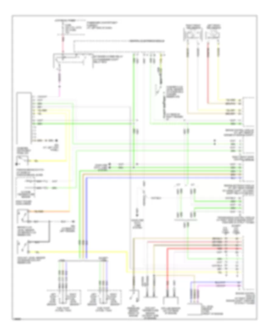
AIR CONDITIONING
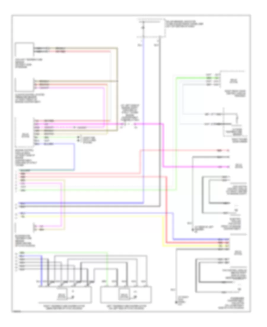
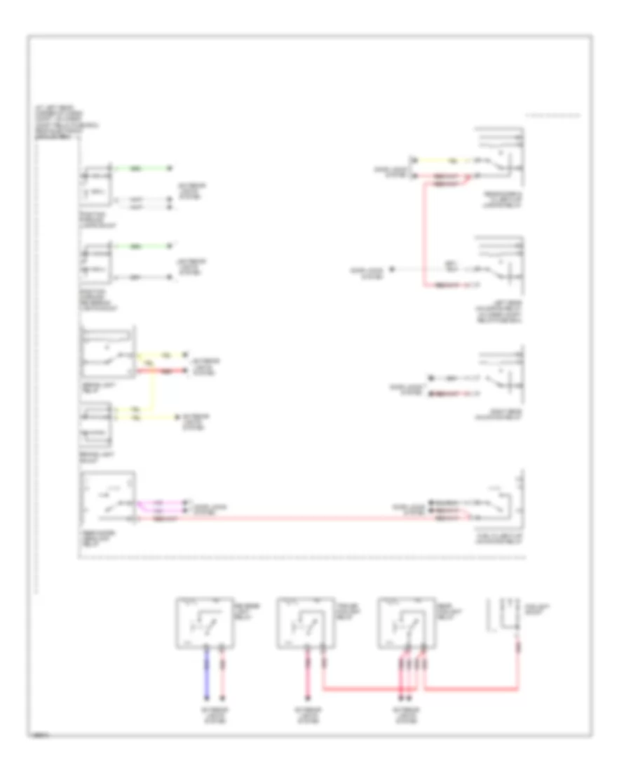
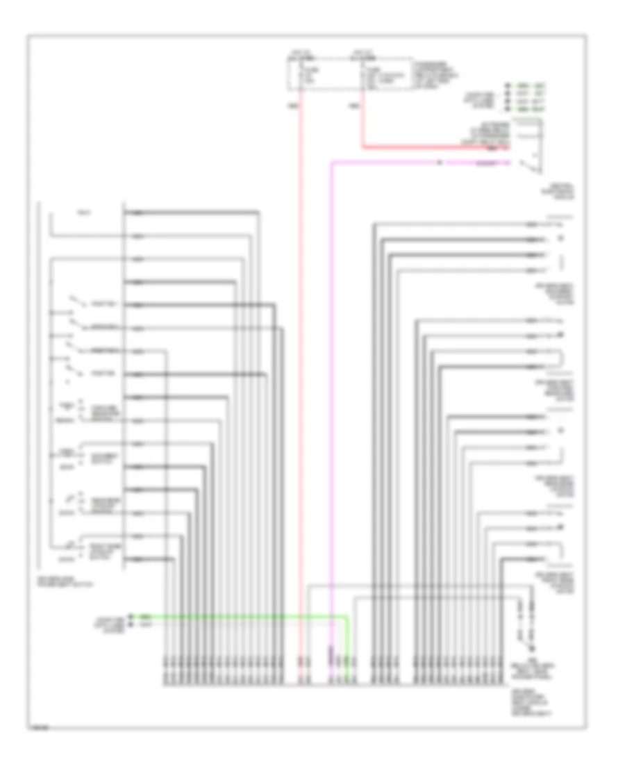
Automatic A/C Wiring Diagram (1 of 2) for Volvo XC90 2004
 https://portal-diagnostov.com/license.html
Automotive Electricians Portal FZCO
Automotive Electricians Portal FZCO
https://portal-diagnostov.com/license.html
https://portal-diagnostov.com/license.html
Automotive Electricians Portal FZCO
Automotive Electricians Portal FZCO
List of elements for Automatic A/C Wiring Diagram (1 of 2) for Volvo XC90 2004:
- (at
- (not used)
- A10
- A11
- A12
- A13
- A14
- A15
- A16
- Air quality sensor (at right side of plenum)
- B10
- B11
- B12
- B13
- B14
- B15
- B16
- B17
- B18
- B19
- B20
- B21
- B22
- Central electronic module (cem)
- Climate control system relay
- Computer data lines system
- Defroster damper motor (near center of hvac housing)
- Electromagnitic clutch (climate control system) (right front of engine)
- Electronic climate control (ecc) module
- Engine compartment fuse/relay box (at left side of engine compartment, forward of strut tower)
- Extended d1 feed relay (in passenger compartment relay box)
- Fuse a8 80a
- Fuse b11 20a
- Fuse b8 10a
- Fuse c1 30a
- Fuse c21 10a
- Fuse c22 5a
- Hot at all times
- Hot w/ engine management system main relay energized
- Nca
- Passenger compartment fuse box (at left end of dash)
- Recirculation damper motor (on lower right side of hvac housing)
- Red
- Right kick panel) g84
- Solid state
- Ventilation/floor damper motor (near center of hvac housing)
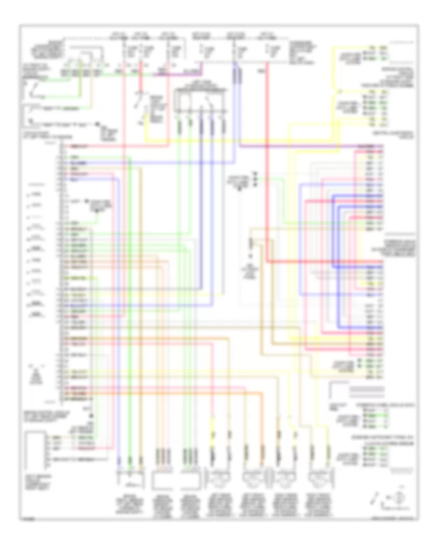
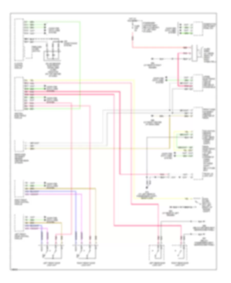
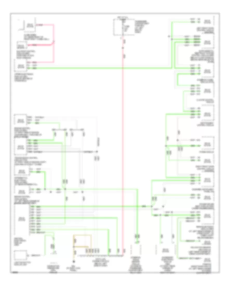
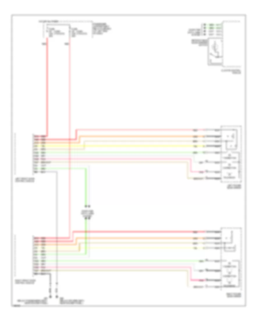
Automatic A/C Wiring Diagram (2 of 2) for Volvo XC90 2004
List of elements for Automatic A/C Wiring Diagram (2 of 2) for Volvo XC90 2004:
- (at left side of engine compt, forward of strut tower) engine compartment fuse/relay box
- (at rear of left fender) g2
- (at right kick panel) g10
- A14
- A18
- A39
- A60
- A68
- B13
- B44
- Climate control system pressure sensor (at right front of engine compartment)
- Computer data lines system
- Coolant temperature sensor (on right side of engine)
- Cooling fan control module (at front center of engine compt)
- Electric cooling fan motor (front of engine compartment)
- Engine control module (ecm) (at right side of engine compartment, forward of strut tower)
- Evaporator temperature sensor (near center of hvac housing)
- Fan control module (behind right side of dash, near blower fan)
- Left temperature damper motor (on left end of hvac housing)
- Nca
- Outside temperature sensor
- Passenger compartment fan motor (on lower right side of hvac housing)
- Red
- Right front door control module (pdm/ddm)
- Right power door mirror
- Right temperature damper motor (near center of hvac housing)
- Solar sensor, indicator alarm & electronic immobilizer (on top center of dash)
- Solid state
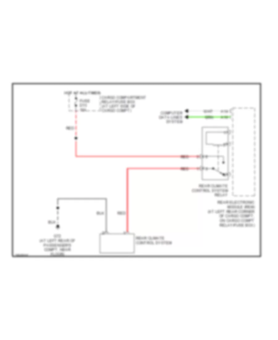
Rear A/C Wiring Diagram for Volvo XC90 2004
List of elements for Rear A/C Wiring Diagram for Volvo XC90 2004:
- A14
- A16
- Cargo compartment relay/fuse box (at left side of cargo compt)
- Computer data lines system
- Fuse d13 15a
- G72 (at left rear of passenger's compt, near floor)
- Hot at all times
- Rear climate control system
- Rear climate control system relay
- Rear electronic module (rem) (at left rear corner of cargo compt, on cargo compt relay/fuse box)
- Red
ANTI-LOCK BRAKES
Anti-lock Brakes Wiring Diagram for Volvo XC90 2004
List of elements for Anti-lock Brakes Wiring Diagram for Volvo XC90 2004:
- (at front of engine compt) vacuum pump switch
- (left side of engine compt) dstc activation module
- A11
- A12
- A13
- A14
- Abs pump motor
- B13
- B17
- B18
- B26
- Brake control module (at left rear corner of engine compt)
- Brake light contact (at top of brake pedal)
- Brake pedal sensor (at left rear corner of engine compt)
- Brake pressure sensor 1 (on brake master cylinder)
- Brake pressure sensor 2 (on brake master cylinder)
- Central electronic module
- Climate control module
- Combined instrument panel dim
- Computer data lines system
- Contact reel
- D12
- Dstc sensor module (under right front seat)
- Engine compartment relay/fuse box (at left side of engine compt)
- Engine control module (at right side of engine compt, forward of strut tower)
- Fuse b12 5a
- Fuse b14 30a
- Fuse b19 30a
- Fuse c16 5a
- Fuse c17 5a
- Fuse c22 5a
- G84 (at right kick panel)
- G93 (at rear of left fender)
- G95 (at rear of left fender)
- Hot at all times
- Hot in on or start
- Left front abs sensor (behind left front wheel, on spindle/ hub assembly)
- Left rear abs sensor (behind left rear wheel, on spindle/ hub assembly)
- Nca
- Passenger compartment relay/fuse box (at left end of dash)
- Pnk
- Red
- Right front abs sensor (behind right front wheel, on spindle/ hub assembly)
- Right rear abs sensor (behind right rear wheel, on spindle/ hub assembly)
- Spin control switch
- Steering angle sensor module (on side of passenger compt relay box)
- Steering wheel module (swm)
- Vacuum pump (at left front of engine)
ANTI-THEFT
Forced Entry Wiring Diagram for Volvo XC90 2004
List of elements for Forced Entry Wiring Diagram for Volvo XC90 2004:
- A11
- A12
- A13
- A14
- A16
- Air conditioning system
- Alarm siren (at inside front of front right wheelwell)
- B12
- B17
- B18
- C18
- Central electronic module
- Climate control module
- Combination instrument panel dim
- Computer data lines system
- D20
- Front mass movement sensor (center of roof)
- Fuse c28 5a
- G66 (below driver's seat, near rocker panel)
- G67 (below passenger's seat, near rocker panel)
- G72 (at left rear of passenger's compt, near floor)
- G93 (at rear of left fender)
- G94 (at rear of right fender)
- G98 (at front center of headliner)
- Hood alarm switch (at left front of engine compt)
- Hot at all times
- Inclination sensor module (left rear corner of cargo compt)
- Key
- Left front door control module
- Left front door lock unit
- Left rear door lock unit
- Passenger compartment relay/fuse box (at left end of dash)
- Pnk
- Rear electronic module (at left rear corner of cargo compt, on cargo compt
- Rear mass movement sensor (center rear of roof)
- Red
- Reduced alarm switch
- Relay/fuse box)
- Right front door control module
- Right front door lock unit
- Right rear door lock unit
- Solar sensor/ electronic immobilizer alarm indicator (on top center of dash)
- Trunk lid lock unit
- Ulk
- Upper electronic module (above center of windshield)
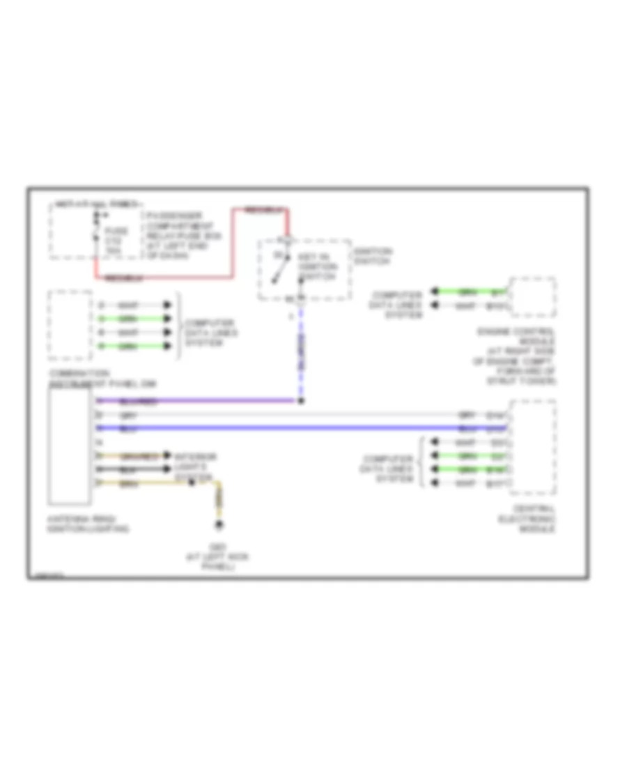
Immobilizer Wiring Diagram for Volvo XC90 2004
List of elements for Immobilizer Wiring Diagram for Volvo XC90 2004:
- Antenna ring/ ignition lighting
- B13
- B17
- B18
- Central electronic module
- Combination instrument panel dim
- Computer data lines system
- D13
- D14
- Engine control module (at right side of engine compt, forward of strut tower)
- Fuse c12 10a
- G83 (at left kick panel)
- Hot at all times
- Ignition switch
- Interior lights system
- Key in ignition switch
- Passenger compartment relay/fuse box (at left end of dash)
BODY CONTROL MODULES
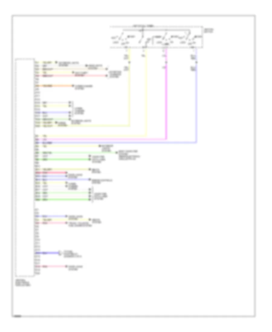
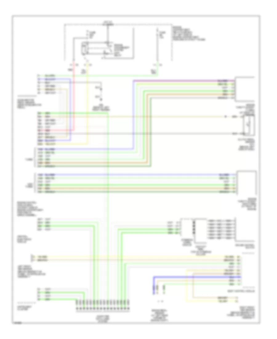
Central Electronic Module Wiring Diagram (1 of 2) for Volvo XC90 2004
List of elements for Central Electronic Module Wiring Diagram (1 of 2) for Volvo XC90 2004:
- 15a
- A10
- A11
- A12
- A13
- A14
- A15
- A16
- A17
- A18
- A19
- A20
- Acc
- Anti-theft system
- B10
- B11
- B12
- B13
- B14
- B15
- B16
- B17
- B18
- B19
- B20
- Body computer system (rear electronic module pin a4)
- C10
- C11
- C12
- C13
- C14
- C15
- C16
- C17
- C18
- C19
- C20
- Central electronic module (cem)
- Computer data lines system
- Door locks system
- Engine controls system
- Exterior lights system
- Headlights system
- Horns system
- Hot at all times
- Ignition switch
- Key in
- Lock
- Off
- Pnk
- Seats system
- Start
- Starting/ charging system
- To fuel pump relay (diagram 2 of 2)
- Trunk, tailgate, fuel doors system
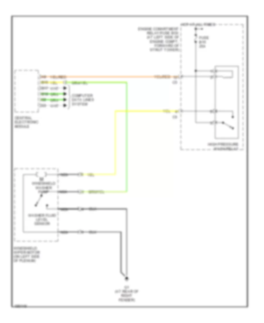
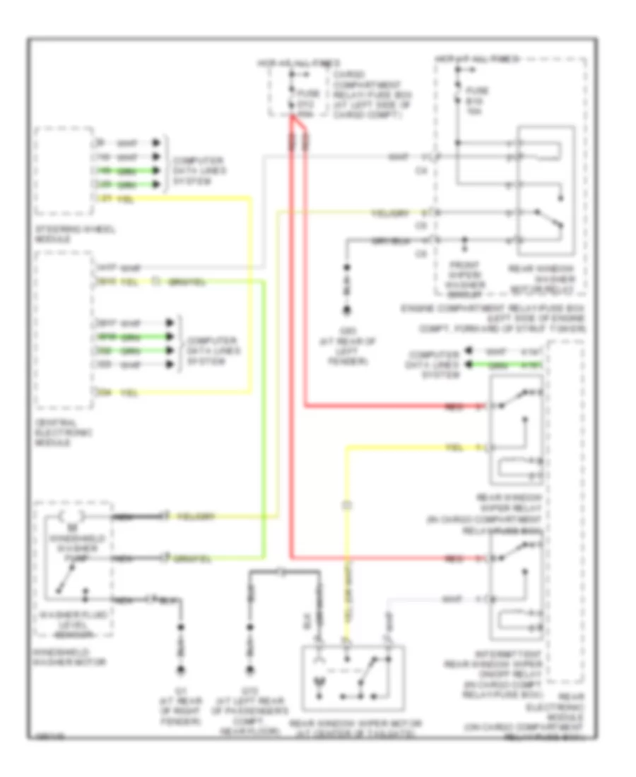
- Wiper/ washer system
- Wiper/washer system
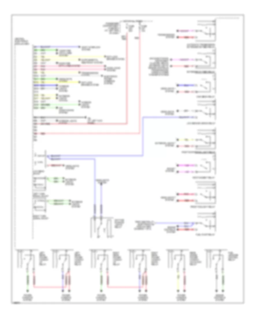
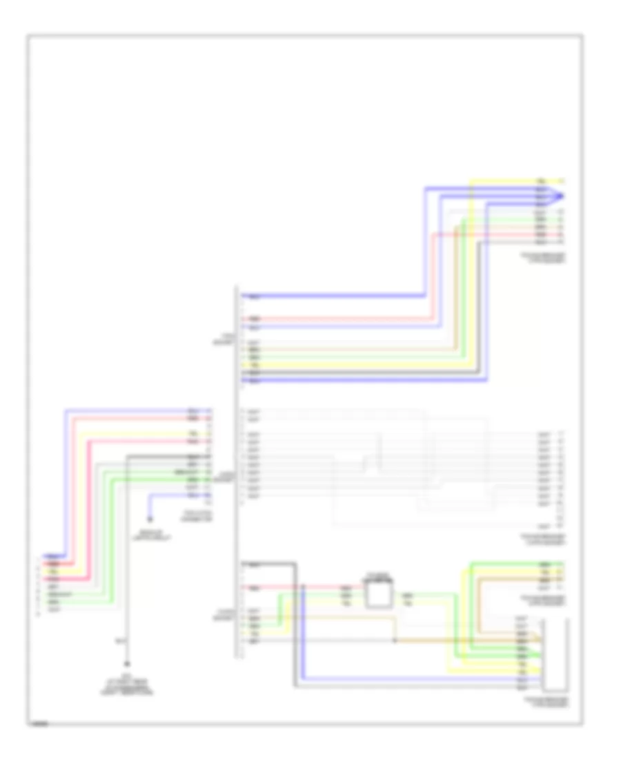
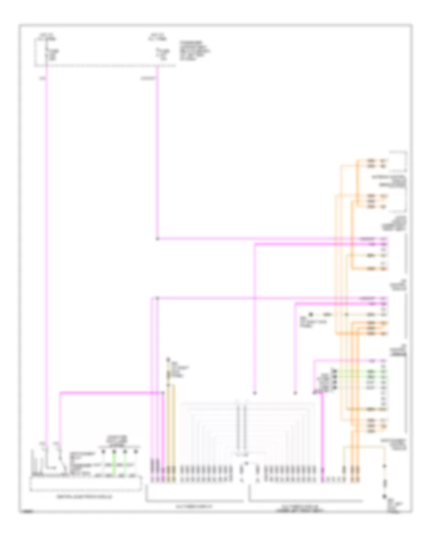
Central Electronic Module Wiring Diagram (2 of 2) for Volvo XC90 2004
List of elements for Central Electronic Module Wiring Diagram (2 of 2) for Volvo XC90 2004:
- Air conditioning system
- Air conditioning, instrument cluster, seats, exterior lights, engine controls, transmissions, horns & wiper/ washer systems
- Anti-lock brakes system
- Automatic transmission extended d2 feed relay
- Central electronic module (cem)
- Computer data lines system
- D10
- D11
- D12
- D13
- D14
- D15
- D16
- D17
- D18
- D19
- D20
- Daytime running lights relay
- Door locks system
- Electronic power steering system
- Engine controls system
- Extended d1 feed relay
- Exterior lights system
- From central electronic a module (cem) (diagram 1 of 2)
- Front foglight relay
- Fuel leakage control relay
- Fuel pump relay
- Fuse c23 20a
- Fuse c27 10a
- G6 (at left kick panel)
- Headlights system
- High beam relay
- Hot at all times
- Infotainment relay
- Interior lights system
- Left rear power window down relay
- Left rear power window up relay
- Left turn signal shunt
- Low beam shunt
- Low beam/bi-xenon relay
- Passenger compartment fuse box (at left end of dash)
- Pnk
- Position/parking light relay
- Power windows system
- Rear doors power window childlock relay
- Red
- Right rear power window down relay
- Right rear power window up relay
- Right turn signal shunt
- Shift interlock system
- Sound system
- Transmissions system
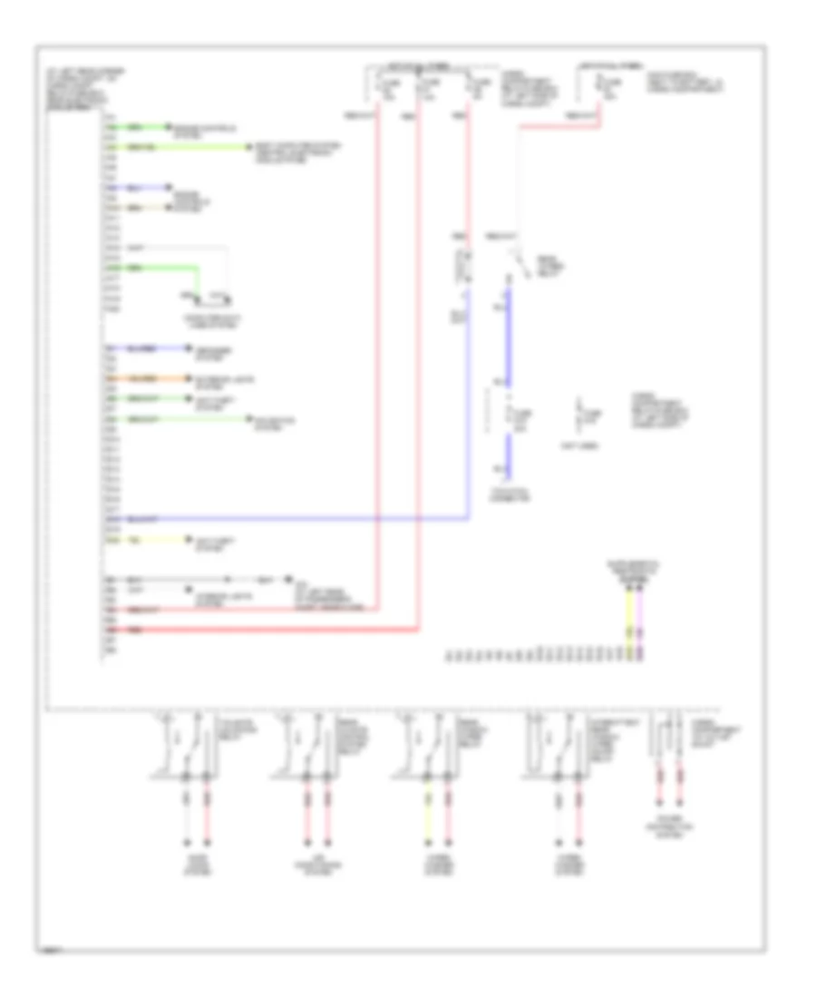
Rear Electronic Module Wiring Diagram (1 of 2) for Volvo XC90 2004
List of elements for Rear Electronic Module Wiring Diagram (1 of 2) for Volvo XC90 2004:
- (at left rear corner of cargo compt, on cargo compt relay/fuse box) rear electronic module (rem)
- (not used)
- A10
- A11
- A12
- A13
- A14
- A15
- A16
- A17
- A18
- A19
- A20
- Air conditioning system
- Anti-theft system
- B10
- B11
- B12
- B13
- B14
- B15
- B16
- B17
- B18
- B19
- B20
- Body computer system (central electronic module pin b6)
- Cargo compartment 12v outlet shunt
- Cargo compartment relay/fuse box (at left side of cargo compt)
- Computer data lines system
- D10
- D11
- D12
- D13
- D14
- D15
- D16
- D17
- D18
- D19
- D20
- Defogger system
- Distribution
- Door locks system
- Engine controls system
- Exterior lights system
- Fuse d1 10a
- Fuse d15 20a
- Fuse d16
- Fuse d2 10a
- Fuse d5 5a
- Fuse e1 40a
- G72 (at left rear of passenger's compt, near floor)
- Hot at all times
- Interior lights system
- Intermittent rear window wiper on/off relay
- Main fuse box (next to battery, in cargo compartment)
- Navigation system
- Power
- Rear 15 feed relay
- Rear climate control system relay
- Rear window wiper relay
- Red
- System
- Tailgate unlocking relay
- Tow hitch connector
- Wiper/ washer system
Rear Electronic Module Wiring Diagram (2 of 2) for Volvo XC90 2004
List of elements for Rear Electronic Module Wiring Diagram (2 of 2) for Volvo XC90 2004:
- (at left rear corner of cargo compt, on cargo compt relay/fuse box) rear electronic module (rem)
- Brake light relay
- Brake light shunt
- Door locks system
- Exterior lights system
- Foglight shunt
- Fuel filler flap unlocking relay
- Left rear unlocking relay (in cargo compt relay/fuse box)
- Pnk
- Position/ parking lamps shunt
- Position/ parking/ reversing lights shunt
- Rear doors & filler flap locking relay
- Rear doors deadlock relay
- Rear foglight relay
- Red
- Reverse light relay
- Right rear unlocking relay
- Trailer foglight relay
COMPUTER DATA LINES
Computer Data Lines Wiring Diagram for Volvo XC90 2004
List of elements for Computer Data Lines Wiring Diagram for Volvo XC90 2004:
- A/t
- A11
- A12
- A13
- A14
- A16
- A18
- Accessory electronic module (aem) (at right rear corner of cargo compartment)
- Alarm siren (at inside front of front right wheelwell)
- B13
- B14
- B17
- B18
- B19
- B20
- B22
- B23/51
- B24/52
- B25/53
- B26/54
- Brake control module (bcm) (at left rear corner of engine compartment)
- Central electronic module (cem)
- Climate control module
- Combined instrument panel dim
- Combustion preheater (cpm) module
- Data link connector (dlc) (below left side of dash)
- Differential electronic module (dem) (at rear differential)
- Engine control module (ecm) (at right side of engine compartment, forward of strut tower)
- Fuse c23 5a
- G84 (at right kick panel)
- Hot at all times
- Inclination sensor (ism) module (left rear corner of cargo compartment)
- Infotainment control module
- Left front door control module (ddm/pdm)
- Lighting switch module (lsm)
- M/t
- Nca
- Parking assistance module (at left rear corner of cargo compartment)
- Passenger compartment fuse box (at left end of dash)
- Phone module
- Pnk
- Power driver seat module (psm) (under driver's seat)
- Rear electronic module (rem) (at left rear corner of cargo compt, on cargo compt relay/fuse box)
- Red
- Right front door control module (ddm/pdm)
- Solid state
- Steering angle sensor module (on side of passenger compartment relay box)
- Steering wheel module (swm)
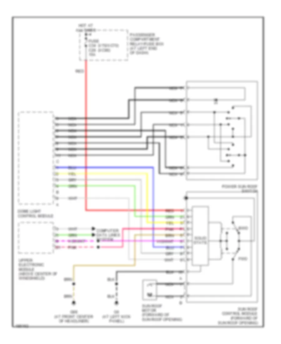
- Sun roof control module (srm) (forward of sun roof opening)
- Transmission control module (tcm) (at right side of engine compt, forward of strut tower)
- Upper electronic module (uem) (above center of windshield)
COOLING FAN
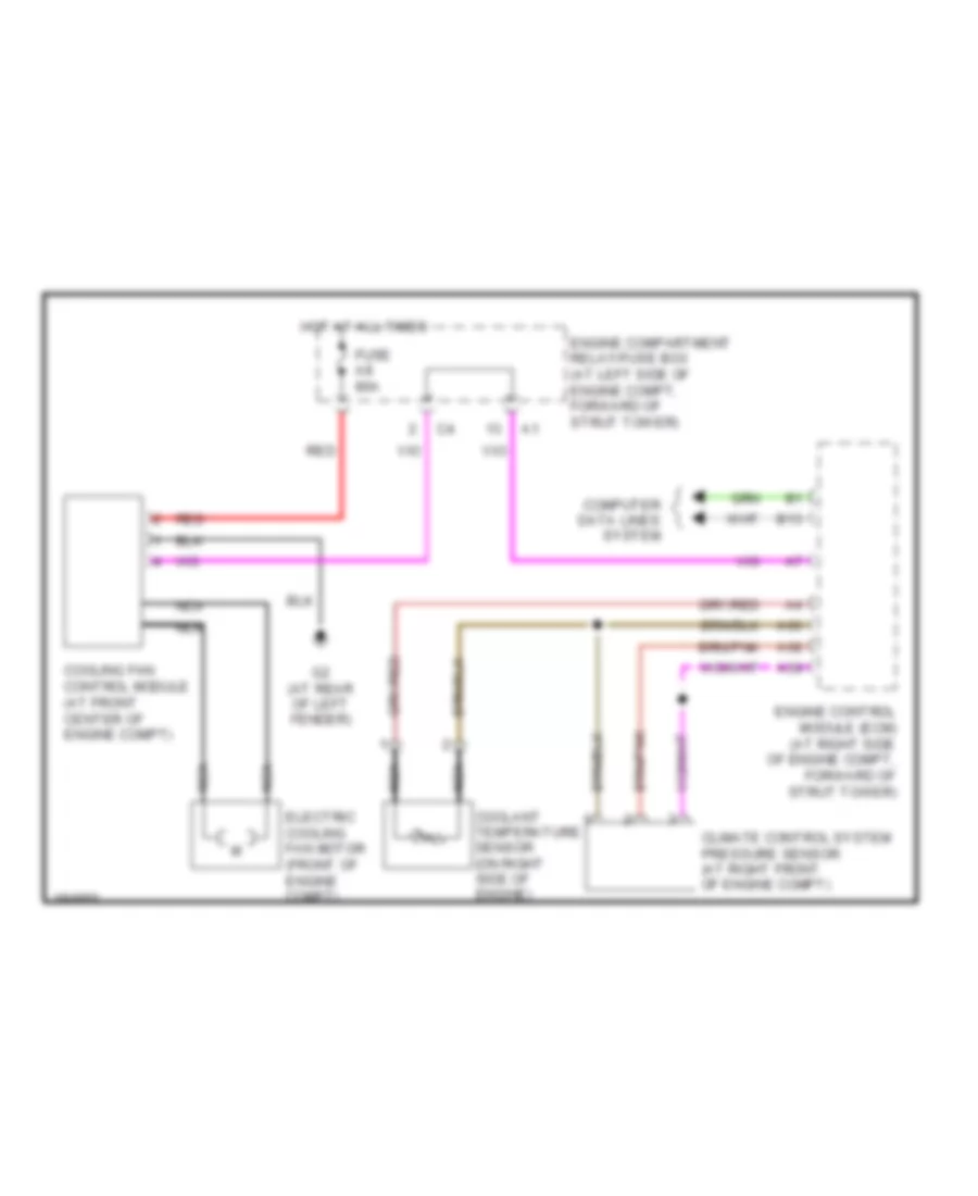
Cooling Fan Wiring Diagram for Volvo XC90 2004
List of elements for Cooling Fan Wiring Diagram for Volvo XC90 2004:
- A39
- A60
- A68
- B13
- Climate control system pressure sensor (at right front of engine compt)
- Computer data lines system
- Coolant temperature sensor (on right side of engine)
- Cooling fan control module (at front center of engine compt)
- Electric cooling fan motor (front of engine compt)
- Engine compartment relay/fuse box (at left side of engine compt, forward of strut tower)
- Engine control module (ecm) (at right side of engine compt, forward of strut tower)
- Fuse a8 80a
- G2 (at rear of left fender)
- Hot at all times
- Nca
- Red
CRUISE CONTROL
Cruise Control Wiring Diagram for Volvo XC90 2004
List of elements for Cruise Control Wiring Diagram for Volvo XC90 2004:
- A19
- A20
- A25
- A35
- A36
- A43
- A59
- Accelerator pedal sensor (near accelerator pedal)
- B11
- B13
- B15
- B17
- B18
- B25
- B38
- Body control module
- Brake pedal sensor (at left rear corner of engine compt)
- Central electronic module
- Clutch pedal sensor (m/t) (behind left side of dash)
- Computer data lines system
- Contact reel (top of steering column)
- Cruise control switch
- Engine compartment relay/fuse box (at left side of engine compartment, forward of strut tower)
- Engine control module (ecm) (on right side of engine compartment, forward of strut tower)
- Engine management system main relay
- Engine throttle body (non-turbo) (at front of engine)
- Engine throttle body (turbo) (at front of engine)
- Fuse b23 5a
- Fuse b8 10a
- G93 (rear of left front fender)
- Hot at all times
- Instrument cluster
- Left front abs sensor (behind respective wheel, on spindle/hub assembly)
- Nca
- Non- turbo
- Red
- Right front abs sensor (behind respective wheel, on spindle/hub assembly)
- Steering wheel module
- Turbo
DEFOGGERS
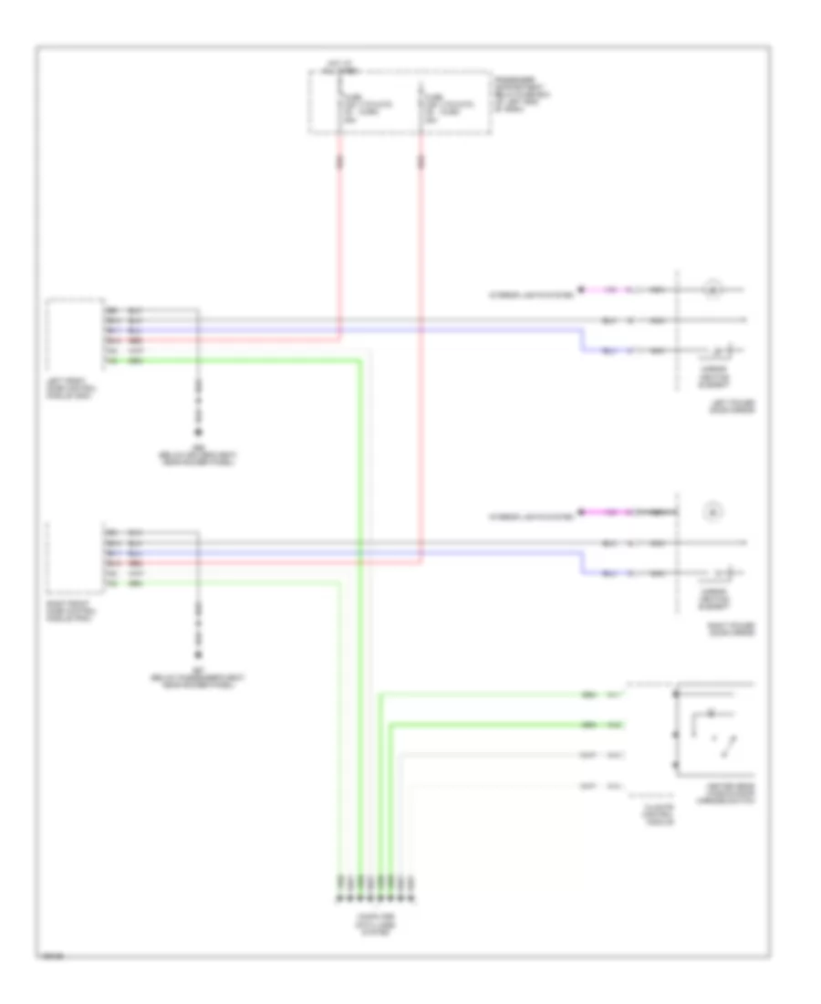
Heated Mirrors Wiring Diagram for Volvo XC90 2004
List of elements for Heated Mirrors Wiring Diagram for Volvo XC90 2004:
- (v70/xc70) (xc90)
- A11
- A12
- A13
- A14
- B10
- B11
- B12
- Climate control module
- Computer data lines system
- Fuse c35 c5 25a
- Fuse c36 c6 25a
- G66 (below driver's seat, near rocker panel)
- G67 (below passenger's seat, near rocker panel)
- Heated rear window/door mirrors switch
- Hot at all times
- Interior lights system
- Left front door control module (ddm)
- Left power door mirror
- Mirror heating element
- Nca
- Passenger compartment relay/fuse box (at left end of dash)
- Red
- Right front door control module (pdm)
- Right power door mirror
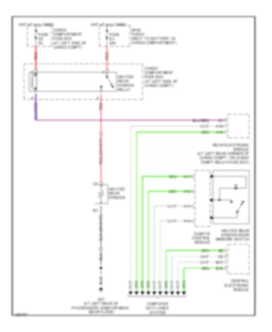
Rear Defogger Wiring Diagram for Volvo XC90 2004
List of elements for Rear Defogger Wiring Diagram for Volvo XC90 2004:
- A11
- A12
- A13
- A14
- A16
- B17
- B18
- Cargo compartment fuse box (at left side of cargo compt)
- Central electronic module
- Climate control module
- Computer data lines system
- Fuse d5 5a
- Fuse e3 40a
- G47 (at left rear of passenger's compartment, near floor)
- Heated rear window
- Heated rear window relay
- Heated rear window/door mirrors switch
- Hot at all times
- Main fuses (next to battery, in cargo compartment)
- Rear electronic module (at left rear corner of cargo compt, on cargo compt relay/fuse box)
- Red
ELECTRONIC POWER STEERING
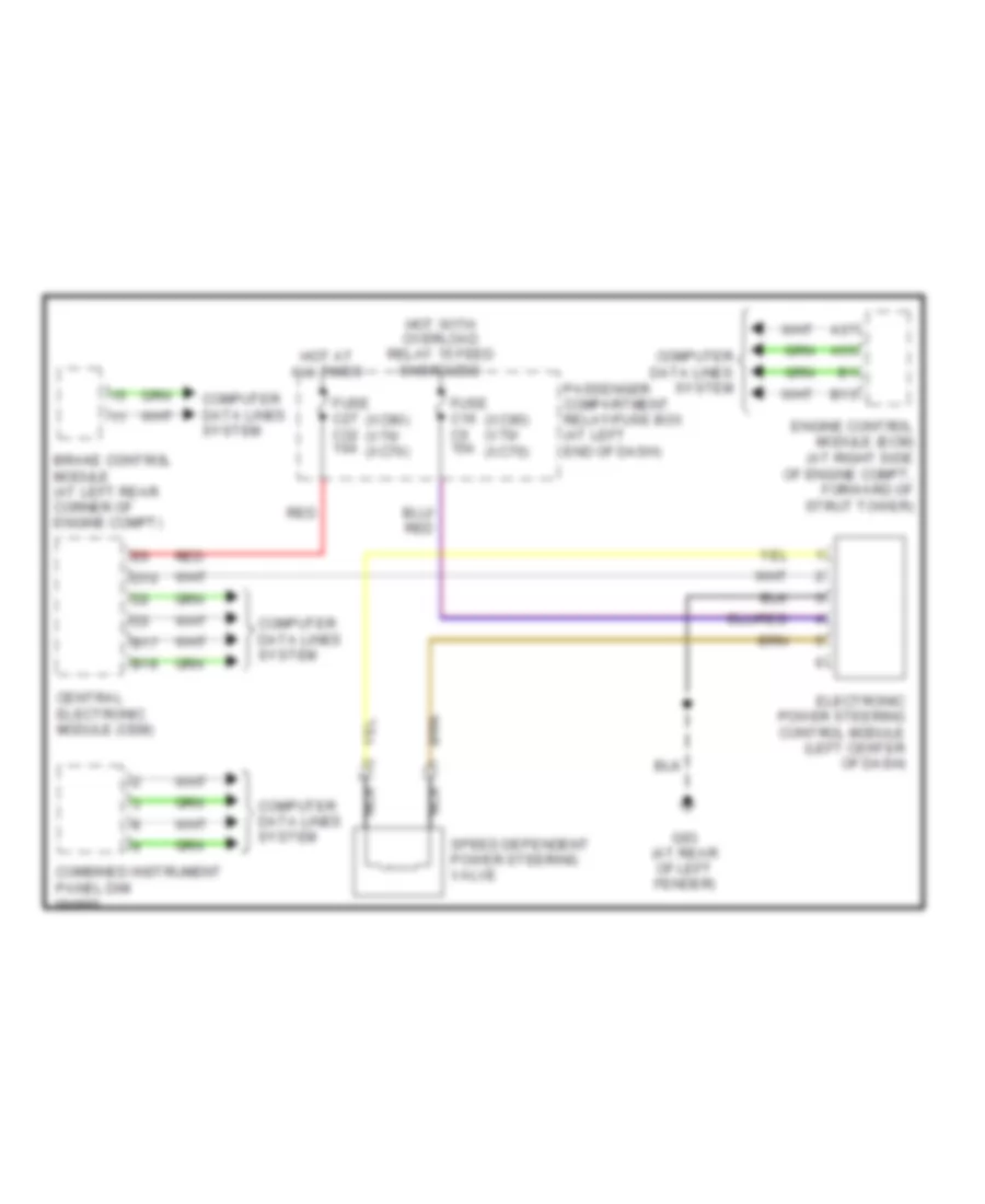
Electronic Power Steering Wiring Diagram for Volvo XC90 2004
List of elements for Electronic Power Steering Wiring Diagram for Volvo XC90 2004:
- (xc90) (v70/ (xc70)
- A37
- A55
- B13
- B17
- B18
- Brake control module (at left rear corner of engine compt)
- Central electronic module (cem)
- Combined instrument panel dim
- Computer data lines system
- D10
- Electronic power steering control module (left center of dash)
- Engine control module (ecm) (at right side of engine compt, forward of strut tower)
- Fuse c16 c5 15a
- Fuse c27 c32 10a
- G93 (at rear of left fender)
- Hot at all times
- Hot with overload relay 15 feed energized
- Nca
- Passenger compartment relay/fuse box (at left end of dash)
- Red
- Speed dependent power steering valve
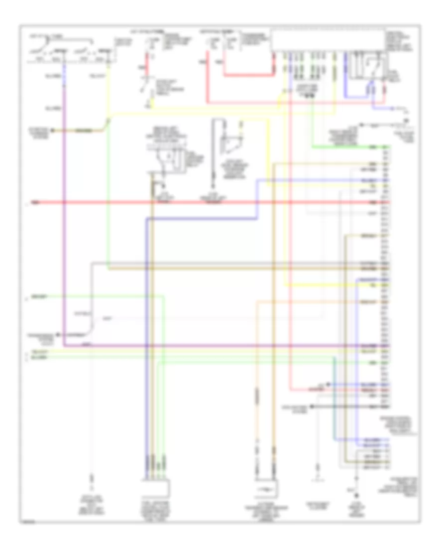
ENGINE PERFORMANCE
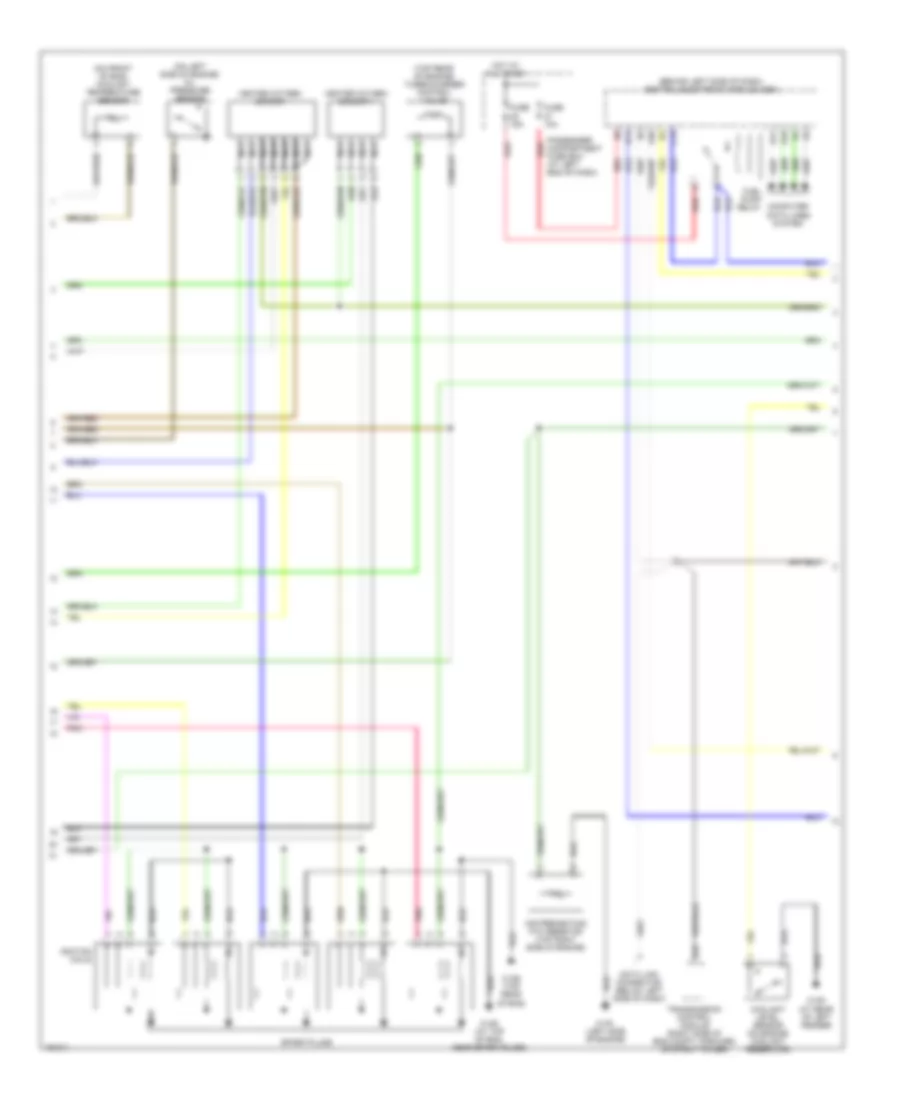
2.5L TURBO
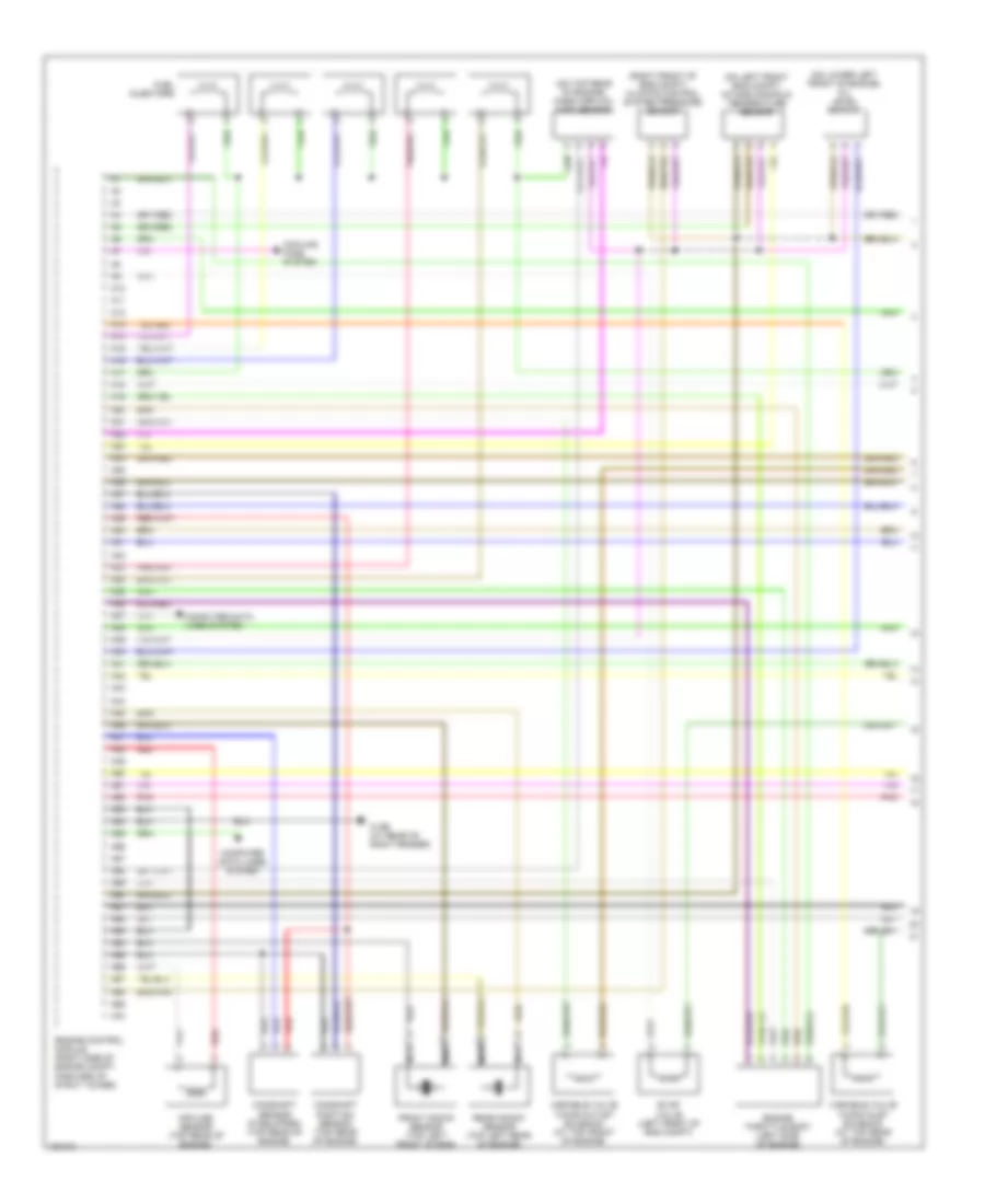
2.5L Turbo, Engine Performance Wiring Diagram (1 of 3) for Volvo XC90 2004
List of elements for 2.5L Turbo, Engine Performance Wiring Diagram (1 of 3) for Volvo XC90 2004:
- (on left front eng compt) intake manifold temperature sensor
- (on lower left front of engine) oil level sensor
- (on top rear of engine) mass airflow (maf) sensor
- (right front of eng compt) climate control system pressure sensor
- 31/96 (at rear of right fender)
- A10
- A11
- A12
- A13
- A14
- A15
- A16
- A17
- A18
- A19
- A20
- A21
- A22
- A23
- A24
- A25
- A26
- A27
- A28
- A29
- A30
- A31
- A32
- A33
- A34
- A35
- A36
- A37
- A38
- A39
- A40
- A41
- A42
- A43
- A44
- A45
- A46
- A47
- A48
- A49
- A50
- A51
- A52
- A53
- A54
- A55
- A56
- A57
- A58
- A59
- A60
- A61
- A62
- A63
- A64
- A65
- A66
- A67
- A68
- A69
- A70
- Camshaft position sensor (top rear of engine)
- Camshaft sensor (if equipped) (top rear of engine)
- Computer data lines system
- Cooling fans system
- Engine control module (right side of engine compt, forward of strut tower)
- Engine throttle body (left side of engine)
- Evap valve (left front of eng compt)
- Front knock sensor (top left front of eng)
- Fuel injectors
- Impulse sensor (top rear of engine)
- Nac
- Nca
- Pnk
- Rear knock sensor (top left rear of engine)
- Red
- Variable valve timing inlet solenoid (at top rear of engine)
- Variable valve timing outlet solenoid (at top front of engine)
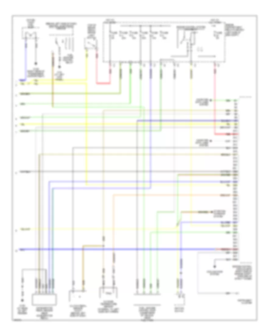
2.5L Turbo, Engine Performance Wiring Diagram (2 of 3) for Volvo XC90 2004
List of elements for 2.5L Turbo, Engine Performance Wiring Diagram (2 of 3) for Volvo XC90 2004:
- (behind left side of dash) central electronic module (cem)
- (on front of eng) coolant temperature sensor
- (on left side of engine) oil pressure sensor
- (top rear of engine) turbocharger control valve
- 31/88 (at top of eng, near spark plugs)
- 31/89 (top rear of eng)
- 31/91 (left side of engine)
- 31/93 (at rear of left fender)
- A20
- Air preheating ptc resistor (top right side of engine)
- B14
- B17
- B18
- B22
- C14
- Computer data lines system
- Coolant level sensor (on engine coolant reservoir)
- Data link connector (below left side of dash)
- Fuel pump relay
- Fuse 10a
- Fuse 15a
- Heated oxygen sensor
- Heated oxygen sensor 1
- Hot at all times
- Ignition coils
- Nca
- Passenger compartment fuse box (at left end of dash)
- Pnk
- Red
- Spark plugs
- Transmission control module (right side of eng compt, forward of strut tower)
2.5L Turbo, Engine Performance Wiring Diagram (3 of 3) for Volvo XC90 2004
List of elements for 2.5L Turbo, Engine Performance Wiring Diagram (3 of 3) for Volvo XC90 2004:
- (behind left side of dash) central electronic module
- (in fuel tank) fuel pump
- (top of brake pedal) brake light switch
- 31/48 (right rear of passenger's compartment)
- 31/6 (at left kick panel)
- 31/93 (at rear of left fender)
- Accelerator pedal sensor (near accelerator pedal)
- B10
- B11
- B12
- B13
- B14
- B15
- B16
- B17
- B18
- B19
- B20
- B21
- B22
- B23
- B24
- B25
- B26
- B27
- B28
- B29
- B30
- B31
- B32
- B33
- B34
- B35
- B36
- B37
- B38
- B39
- B40
- B41
- B42
- B43
- B44
- B45
- B46
- B47
- B48
- Clutch pedal sensor (w/m/t) (behind left side of dash)
- Computer data lines system
- Cooling fans system
- Engine compartment relay/fuse box (left side of eng compt)
- Engine control module (ecm) (right side of engine compt, forward of strut tower)
- Engine control system main relay
- Fuel leakage control pump (under rear of vehicle, near fuel tank)
- Fuel leakage control relay
- Fuse 10a
- Fuse 15a
- Fuse 20a
- Fuse 5a
- Hot at all times
- Ignition switch
- Instrument cluster
- Nca
- Outside temperature sensor (integral to left sideview mirror)
- Red
- Starting/ charging system
2.9L TURBO
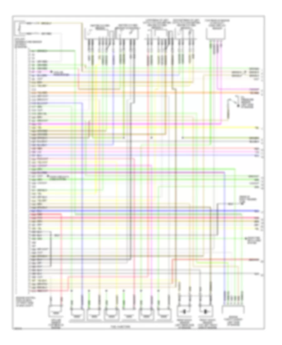
2.9L Turbo, Engine Performance Wiring Diagram (1 of 3) for Volvo XC90 2004
List of elements for 2.9L Turbo, Engine Performance Wiring Diagram (1 of 3) for Volvo XC90 2004:
- (downstream of left catalytic converter) heated oxygen sensor 4
- (rear of right fender) 31/96
- (top rear of engine in air duct) mass airflow sensor
- (upstream of left catalytic converter) heated oxygen sensor 3
- A10
- A11
- A12
- A13
- A14
- A15
- A16
- A17
- A18
- A19
- A20
- A21
- A22
- A23
- A24
- A25
- A26
- A27
- A28
- A29
- A30
- A31
- A32
- A33
- A34
- A35
- A36
- A37
- A38
- A39
- A40
- A41
- A42
- A43
- A44
- A45
- A46
- A47
- A48
- A49
- A50
- A51
- A52
- A53
- A54
- A55
- A56
- A57
- A58
- A59
- A60
- A61
- A62
- A63
- A64
- A65
- A66
- A67
- A68
- A69
- A70
- Computer data lines system
- Coolant temperature sensor (on front of engine)
- Cooling fans system
- Engine control module (ecm) (at right side of eng compt)
- Engine throttle body (left side of engine)
- Front knock sensor (top left front side of engine)
- Fuel injectors
- Heated oxygen sensor
- Heated oxygen sensor (diagnosis 1)
- Impulse sensor (top rear of engine)
- Nca
- Oil pressure sensor (left side of engine)
- Pnk
- Rear knock sensor (left rear side of engine)
- Red
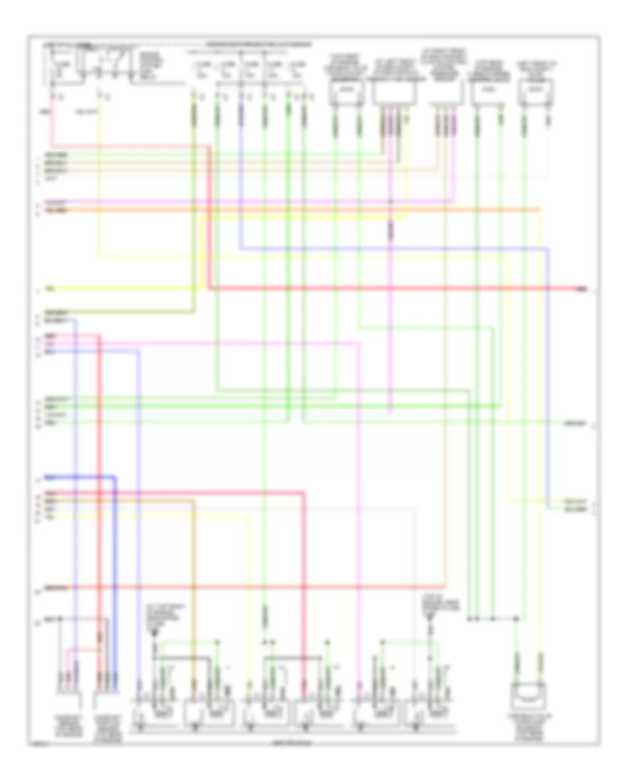
2.9L Turbo, Engine Performance Wiring Diagram (2 of 3) for Volvo XC90 2004
List of elements for 2.9L Turbo, Engine Performance Wiring Diagram (2 of 3) for Volvo XC90 2004:
- (at left front of eng compt) intake manifold temperature sensor
- (at right front of eng compart) climate control system pressure sensor
- (at top front of engine, near spark plugs) 31/88
- (left front of eng compt) evap valve
- (top front of engine) variable valve timing outlet solenoid
- (top of engine, near spark plugs) 31/89
- (top rear of engine) turbocharger control valve
- Camshaft position sensor (top rear of engine)
- Camshaft sensor (top rear of engine)
- Engine compartment relay/fuse box
- Engine control system main relay
- Fuse 10a
- Fuse 15a
- Fuse 20a
- Fuse 5a
- Hot at all times
- Ignition coils
- Pnk
- Red
- Variable valve timing inlet solenoid (top rear of engine)
2.9L Turbo, Engine Performance Wiring Diagram (3 of 3) for Volvo XC90 2004
List of elements for 2.9L Turbo, Engine Performance Wiring Diagram (3 of 3) for Volvo XC90 2004:
- (behind left side of dash) central electronic module (cem)
- 31/48 (right rear of passenger's compartment, near floor)
- 31/6 (left kick panel)
- 31/93 (rear of left fender)
- A/c system
- A20
- Acc
- Accelerator pedal (ap) position sensor (near accelerator pedal)
- B10
- B11
- B12
- B13
- B14
- B15
- B16
- B17
- B18
- B19
- B20
- B21
- B22
- B23
- B24
- B25
- B26
- B27
- B28
- B29
- B30
- B31
- B32
- B33
- B34
- B35
- B36
- B37
- B38
- B39
- B40
- B41
- B42
- B43
- B44
- B45
- B46
- B47
- B48
- C14
- Central electronic module (behind left side of dash)
- Computer data lines system
- Coolant level sensor (on engine coolant reservoir)
- Cooling fans system
- Data link connector (dlc) (below left side of dash)
- Engine compartment relay/fuse box
- Engine control module (ecm) (right side of eng compt)
- Fuel leakage control pump (under rear of vehicle, near fuel tank)
- Fuel leakage control relay
- Fuel pump (in fuel tank)
- Fuel pump relay
- Fuse 10a
- Fuse 5a
- Hot at all times
- Ignition switch
- Instrument cluster
- Lock
- Nca
- Outside temperature sensor (integral to left sideview mirror)
- Passenger compartment fuse box
- Red
- Run
- Start
- Starting/ charging system
- Stoplight switch (top of brake pedal)
- Transmission system (w/a/t)
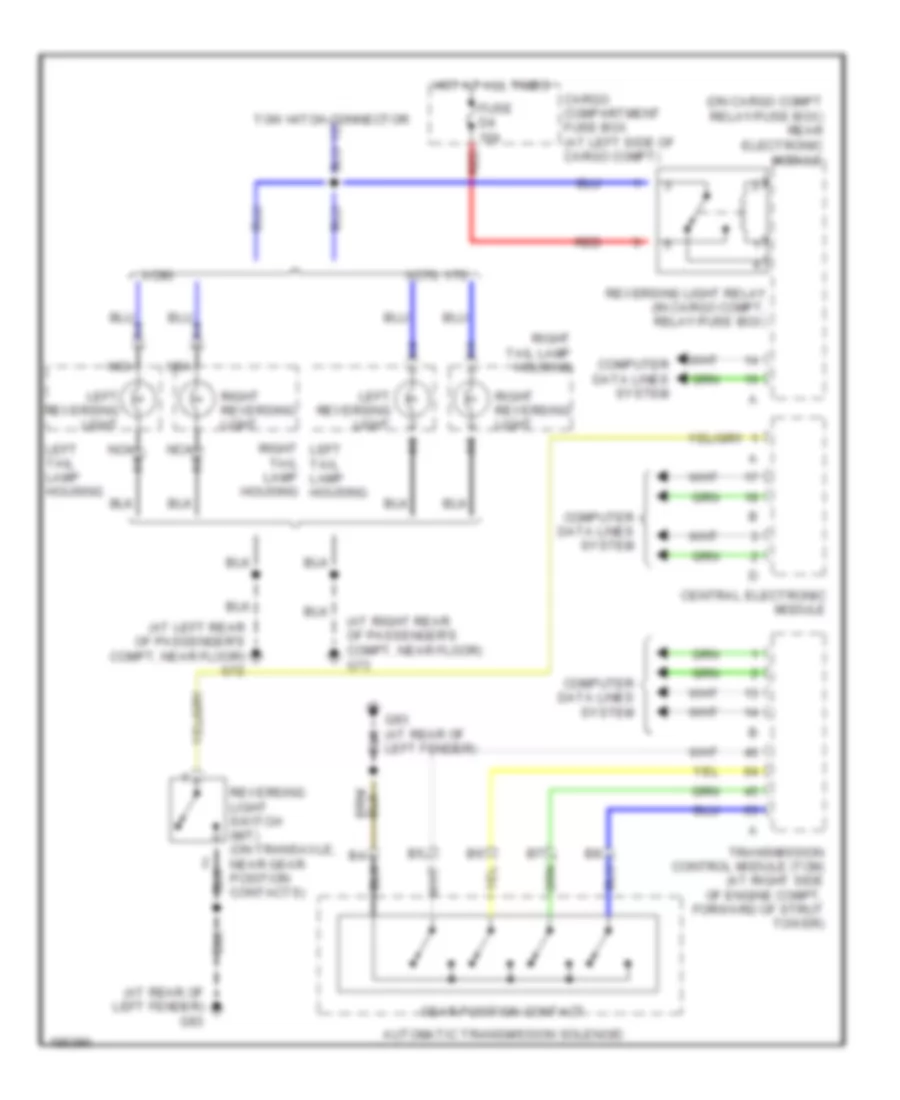
EXTERIOR LIGHTS
Back-up Lamps Wiring Diagram for Volvo XC90 2004
List of elements for Back-up Lamps Wiring Diagram for Volvo XC90 2004:
- (at left rear of passenger's compt, near floor) g72
- (at rear of left fender) g93
- (at right rear of passenger's compt, near floor) g73
- (on cargo compt relay/fuse box) rear electronic module
- Automatic transmission solenoid
- Cargo compartment fuse box (at left side of cargo compt)
- Central electronic module
- Computer data lines system
- Fuse d4 10a
- G93 (at rear of left fender)
- Gear position contact
- Hot at all times
- Left reversing light
- Left tail lamp housing
- Nca
- Nca a6
- Red
- Reversing light relay (in cargo compt, relay/fuse box)
- Reversing light switch (m/t) (on transaxle, near gear position contacts)
- Right left tail lamp housing
- Right reversing light
- Right tail lamp housing
- Tail lamp housing
- Tow hitch connector
- Transmission control module (tcm) (at right side of engine compt, forward of strut tower)
- Xc70, v70
- Xc90
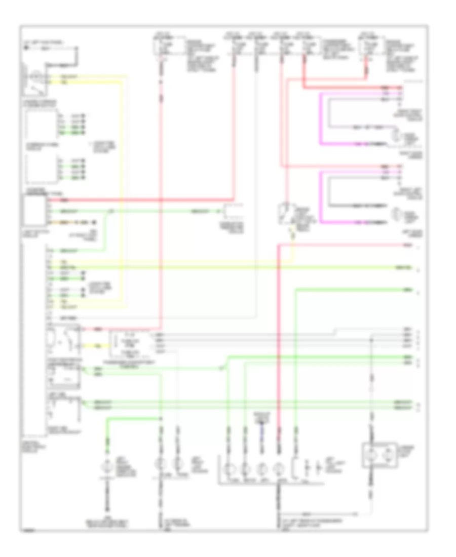
Exterior Lamps Wiring Diagram (1 of 3) for Volvo XC90 2004
List of elements for Exterior Lamps Wiring Diagram (1 of 3) for Volvo XC90 2004:
- (at left kick panel) g6
- (at left rear of passenger's compt, near floor g72
- (at rear of left fender) g93
- B/u
- Back-up lights circuit
- Brake light contact (at top of brake pedal)
- Central electronic module
- Combined instrument panel
- Combustion preheater module
- Computer data lines system
- Door mirror light
- Engine compartment relay/fuse box (at left side of engine compt, forward of strut tower)
- Fog
- Front left door control module
- Front right door control module
- Fuse a2 60a
- Fuse b12 5a
- Fuse c22 5a
- Fuse c23 20a
- Fuse c32 7.5a
- Fuse c33 7.5a
- Fuse c5 25a
- Fuse c6 25a
- G66 (below driver's seat, near rocker panel)
- G84 (at right kick panel)
- Hazard warning flasher switch
- Hot at all times
- Left cem indicator shunt
- Left door mirror
- Left front fender direction indicator
- Left front lamp housing
- Left tail light lamp housing
- License plate light
- Light switch module
- Nca
- Park
- Passenger compartment fuse box
- Passenger compartment relay/fuse box (at left end of dash)
- Pnk
- Position/parking lights relay
- Red
- Right cem indicator shunt
- Right door mirror
- Steering wheel module
- Stop
- Tail
- Turn
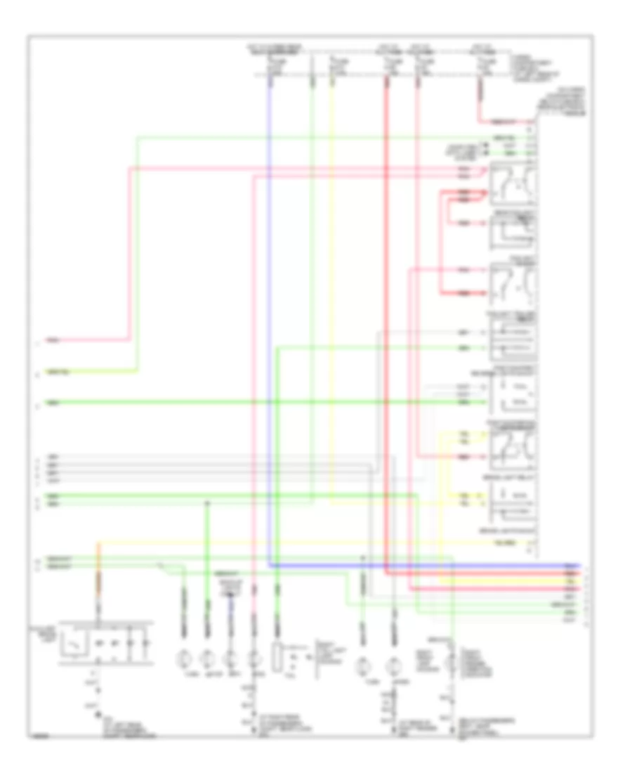
Exterior Lamps Wiring Diagram (2 of 3) for Volvo XC90 2004
List of elements for Exterior Lamps Wiring Diagram (2 of 3) for Volvo XC90 2004:
- (at rear of right fender) g94
- (at right rear of passenger's compt, near floor) g73
- (below passenger's seat, near rocker panel) g67
- (on cargo compartment relay/fuse box) rear electronic module
- Auxiliary brake light
- B/u
- Back-up lights circuit
- Brake light relay
- Brake lights shunt
- Cargo compartment fuse box (at left rear of cargo compt)
- Computer data lines system
- Fog
- Foglight shunt
- Foglight trailer relay
- Fuse d14 7.5a
- Fuse d15 20a
- Fuse d2 10a
- Fuse d3 15a
- Fuse d9 15a
- G72 (at left rear of passenger's compt, near floor)
- Hot at all times
- Hot w/15 feed rear relay energized
- Nca
- Park
- Pnk
- Position/park/ reverse lights shunt
- Position/parking lights shunt
- Rear foglight relay
- Red
- Right front fender direction indicator
- Right front lamp housing
- Right tail light lamp housing
- Stop
- Tail
- Turn
Exterior Lamps Wiring Diagram (3 of 3) for Volvo XC90 2004
List of elements for Exterior Lamps Wiring Diagram (3 of 3) for Volvo XC90 2004:
- 13-pin socket
- 7-pin socket
- 7/4-pin socket
- Back-up lights circuit
- G73 (at right rear
- Of passenger's compt, near floor)
- Pnk
- Red
- Tow hitch connector
- Towbar converter
- Towing bracket (13-pin socket)
- Towing bracket (4-pin socket)
- Towing bracket (7-pin socket)
GROUND DISTRIBUTION
Ground Distribution Wiring Diagram for Volvo XC90 2004
List of elements for Ground Distribution Wiring Diagram for Volvo XC90 2004:
- 15-feed overload relay
- Accelerator pedal sensor
- Accessory electronic module (aem)
- Air preheating ptc resistor
- Alarm siren scm
- Antenna ring/ ignition switch lighting
- Audio module
- Automatic transmission
- Auxiliary brake light
- Auxiliary heater
- Auxiliary heater fuel pump
- Bass speaker
- Bass speaker system relay
- Battery
- Brake control module
- Brake fluid level sensor
- Capacitor
- Cargo compartment 12v outlet
- Cd control module mp2
- Ceiling light switch unit
- Central electronic module (cem)
- Climate control module
- Combined instrument panel
- Combustion preheat module (cpm)
- Coolant level sensor
- Cooling fan control module
- Data link connector
- Differential electronic module
- Dome light control module
- Driver information module
- Driver power seat module (psm)
- Electronic power steering control module
- Electronic throttle module (etm)
- Engine control module
- Fan control module
- Feed pump ejectors
- Front 12v outlet
- Front mass movement sensor
- Fuel leakage control relay
- Fuel pump
- Fuel pump control module
- G1 (at rear of right fender)
- G10 (at right kick panel)
- G2 (at rear of left fender)
- G47 (at left rear of passenger's compt, near floor)
- G48 (at right rear of passenger's compt, near floor)
- G53 (left side of engine compt)
- G6 (at left kick panel)
- G66 (below driver's seat, near rocker panel)
- G67 (below passenger's seat, near rocker panel)
- G72 (at left rear of passenger's compt, near floor)
- G73 (at right rear of passenger's compt, near floor)
- G83 (at left kick panel)
- G84 (at right kick panel)
- G88 (at top of engine, near spark plugs)
- G89 (at top of engine, near spark plugs)
- G91 (at left rear of engine)
- G93 (at rear of left fender)
- G94 (at rear of right front fender)
- G95 (at rear of left fender)
- G96 (at rear of right fender)
- G98 (at front center of headliner)
- Gear selector module
- Glove compt light
- Hazard warning flasher switch
- Headlights high pressure wash
- Heated rear window
- Hood alarm contact
- Horns 1 & 2
- Ignition coil 1
- Ignition coil 2
- Ignition coil 3
- Ignition coil 4
- Ignition coil 5
- Inclination sensor module (ism)
- Infotainment control module
- Intermittent windshield wiper relay
- Left front courtesy light
- Left front door control module (ddm)
- Left front door directional indicator
- Left front foglight
- Left front lamp housing
- Left headlamp level adjustment motor
- Left inflatable curtain igniter shield
- Left rear door deadlock relay
- Left rear door lock unit
- Left rear power window switch
- Left seat heater
- Left tail light lamp housing
- Left vanity mirror lighting
- License plate light
- Light switch module
- Mp control module mp1
- Multimedia module
- Parking assistance module
- Passenger power seat module
- Phone module
- Rain sensor module
- Rear 12v outlet
- Rear climate control system
- Rear electronic module (rem)
- Rear mass movement sensor
- Rear reading lamp
- Rear window washer motor relay
- Rear window washer pump
- Rear window wiper motor
- Reversing light contact
- Right front courtesy light
- Right front door control module (pdm)
- Right front door directional indicator
- Right front fog light
- Right front lamp housing
- Right headlight level adjustment motor
- Right rear door deadlock relay
- Right rear door lock unit
- Right rear power window switch
- Right seat heater
- Right tail light lamp housing
- Right vanity mirror lighting
- Road traffic information
- Rti display
- Shift lock solenoid
- Steering angle sensor module
- Steering wheel module
- Subwoofer module
- Sun roof control module
- Sunroof control module
- Suspension module
- Third row seat reading light
- Towing bracket wiring
- Transmission control module (tcm)
- Trunk lid lock unit
- Upper electronic module (uem)
- Vacuum pump
- Washer fluid level sensor
- Windshield washer motor relay
- Windshield washer pump
- Windshield wiper motor
- X-feed overload relay
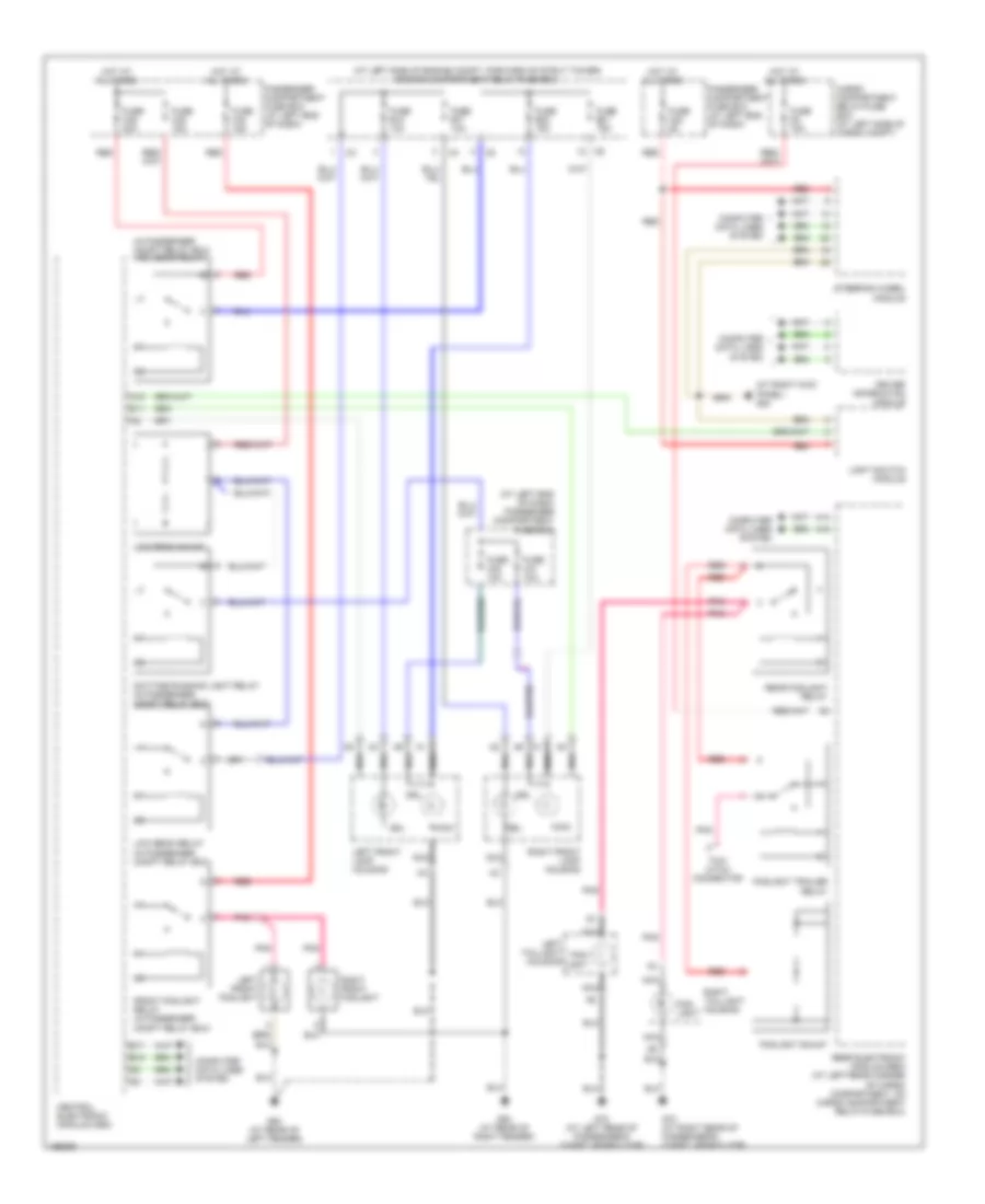
HEADLIGHTS
Headlights Wiring Diagram, with Xenon Lamps for Volvo XC90 2004
List of elements for Headlights Wiring Diagram, with Xenon Lamps for Volvo XC90 2004:
- (at left end of dash) passenger compartment fuse box
- (at left side of engine compt, forward of strut tower) engine compartment relay/fuse box
- (at right kick panel) g84
- (in passenger compt relay box) high beam relay
- A14
- A16
- A18
- B17
- B18
- Cargo compartment relay/fuse box (at left side of cargo compt)
- Central electronic module (cem)
- Computer data lines system
- D11
- Daytime running light relay (in passenger compt relay box)
- Driver information module
- Drl
- Fog- light
- Foglight shunt
- Foglight trailer relay
- Front foglight relay (in passenger compt relay box)
- Fuse b17 10a
- Fuse b18 10a
- Fuse b20 15a
- Fuse b21 15a
- Fuse c22 5a
- Fuse c30 10a
- Fuse c31 10a
- Fuse c34 15a
- Fuse c36 20a
- Fuse c38 15a
- Fuse d2 10a
- G72 (at left rear of passenger's compt, near floor)
- G73 (at right rear of passenger's compt, near floor)
- G93 (at rear of left fender)
- G94 (at rear of right fender)
- Gdl
- Hot at all times
- Left front foglight
- Left front lamp housing
- Left taillight housing
- Light switch module
- Low beam relay (in passenger compt relay box)
- Low beam shunt
- Main
- Nca
- Passenger compartment fuse box (at left end of dash)
- Pnk
- Rear electronic module (rem) (at left rear corner of cargo compartment, on cargo compartment relay/fuse box)
- Rear foglight relay
- Red
- Right front foglight
- Right front lamp housing
- Right taillight housing
- Steering wheel module
- Tow hitch connector
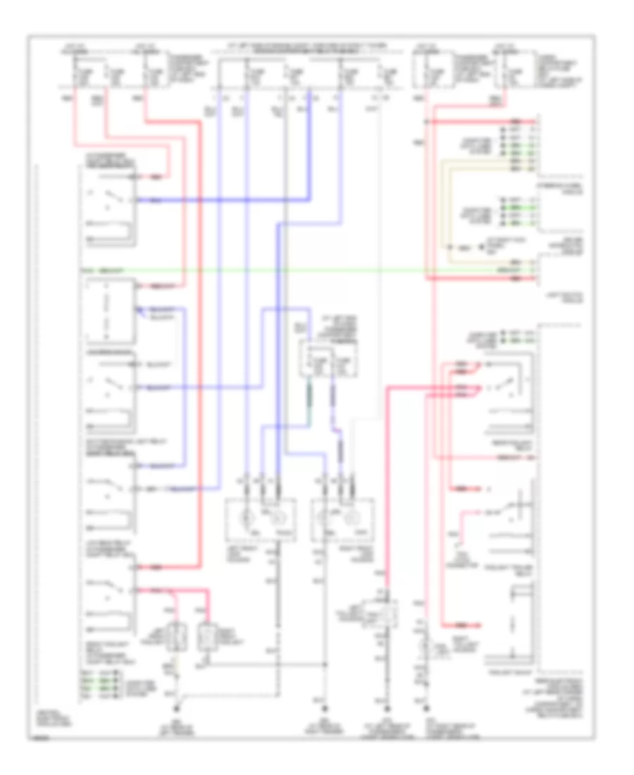
Headlights Wiring Diagram, without Xenon Lamps for Volvo XC90 2004
List of elements for Headlights Wiring Diagram, without Xenon Lamps for Volvo XC90 2004:
- (at left end of dash) passenger compartment fuse box
- (at left side of engine compt, forward of strut tower) engine compartment relay/fuse box
- (at right kick panel) g84
- (in passenger compt relay box) high beam relay
- A14
- A16
- A18
- B17
- B18
- Cargo compartment relay/fuse box (at left side of cargo compt)
- Central electronic module (cem)
- Computer data lines system
- Daytime running light relay (in passenger compt relay box)
- Driver information module
- Drl
- Fog- light
- Foglight shunt
- Foglight trailer relay
- Front foglight relay (in passenger compt relay box)
- Fuse b17 10a
- Fuse b18 10a
- Fuse b20 15a
- Fuse b21 15a
- Fuse c22 5a
- Fuse c30 10a
- Fuse c31 10a
- Fuse c34 15a
- Fuse c36 20a
- Fuse c38 15a
- Fuse d2 10a
- G72 (at left rear of passenger's compt, near floor)
- G73 (at right rear of passenger's compt, near floor)
- G93 (at rear of left fender)
- G94 (at rear of right fender)
- Gdl
- Hot at all times
- Left front foglight
- Left front lamp housing
- Left taillight housing
- Light switch module
- Low beam relay (in passenger compt relay box)
- Low beam shunt
- Main
- Nca
- Passenger compartment fuse box (at left end of dash)
- Pnk
- Rear electronic module (rem) (at left rear corner of cargo compartment, on cargo compartment relay/fuse box)
- Rear foglight relay
- Red
- Right front foglight
- Right front lamp housing
- Right taillight housing
- Steering wheel module
- Tow hitch connector
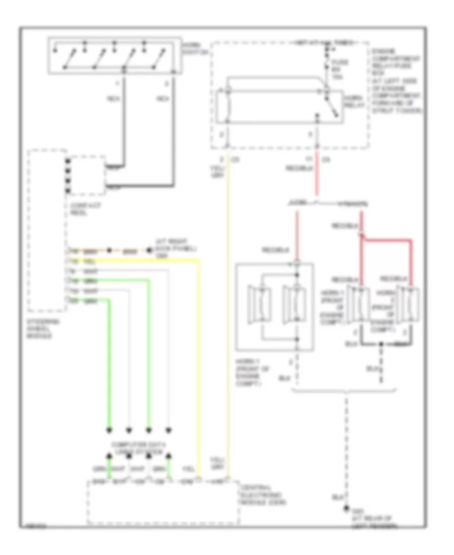
HORN
Horn Wiring Diagram for Volvo XC90 2004
List of elements for Horn Wiring Diagram for Volvo XC90 2004:
- (at left side of engine compartment, forward of strut tower)
- (at right kick panel) g84
- A19
- B17
- B18
- Central electronic module (cem)
- Computer data lines system
- Contact reel
- D12
- Engine compartment relay/fuse box
- Fuse b9 15a
- G93 (at rear of left fender)
- Horn (front of engine compt)
- Horn 1 (front of engine compt)
- Horn relay
- Horn switch
- Hot at all times
- Nca
- Steering wheel module
- V70/xc70
- Xc90
INSTRUMENT CLUSTER
Instrument Cluster Wiring Diagram for Volvo XC90 2004
List of elements for Instrument Cluster Wiring Diagram for Volvo XC90 2004:
- (at rear of right fender) g1
- (in passenger compt relay box)
- (v70, xc70) (xc90)
- 2.4l non- turbo
- A/t
- Brake control module (at left rear of corner of engine compt)
- Brake fluid level sensor (on brake fluid reservoir)
- Central electronic module
- Combined instrument panel dim
- Computer data lines system
- Coolant level sensor (on engine coolant reservoir)
- Coolant temperature sensor (on right side of engine)
- Engine control module (at right side of engine compt, forward of strut tower)
- Except 2.4l non- turbo
- Except v70r
- Extended di-feed relay
- Fuel pump (in fuel tank)
- Fuse c24 c21 10a
- G83 (at left kick panel)
- G93 (at rear of left fender)
- Hot at all times
- Impulse sensor (on top rear of engine)
- Left front abs sensor
- Left pump fuel level sensor
- M/t
- Nca
- Oil level sensor (v70r) (front of engine)
- Oil pressure sensor (front of engine)
- Outside temperature sensor
- Parking brake switch (at base of parking brake lever)
- Passenger compartment fuse box (at left end of dash)
- Rear electronic module (at left rear corner of cargo compt, on cargo compt relay/fuse box)
- Red
- Right front abs sensor
- Right front door control module
- Right power door mirror
- Right pump fuel level sensor
- Transmission control module (at right side of engine compt, forward of strut tower)
- V70r
- Washer fluid level sensor (in windshield washer reservoir)
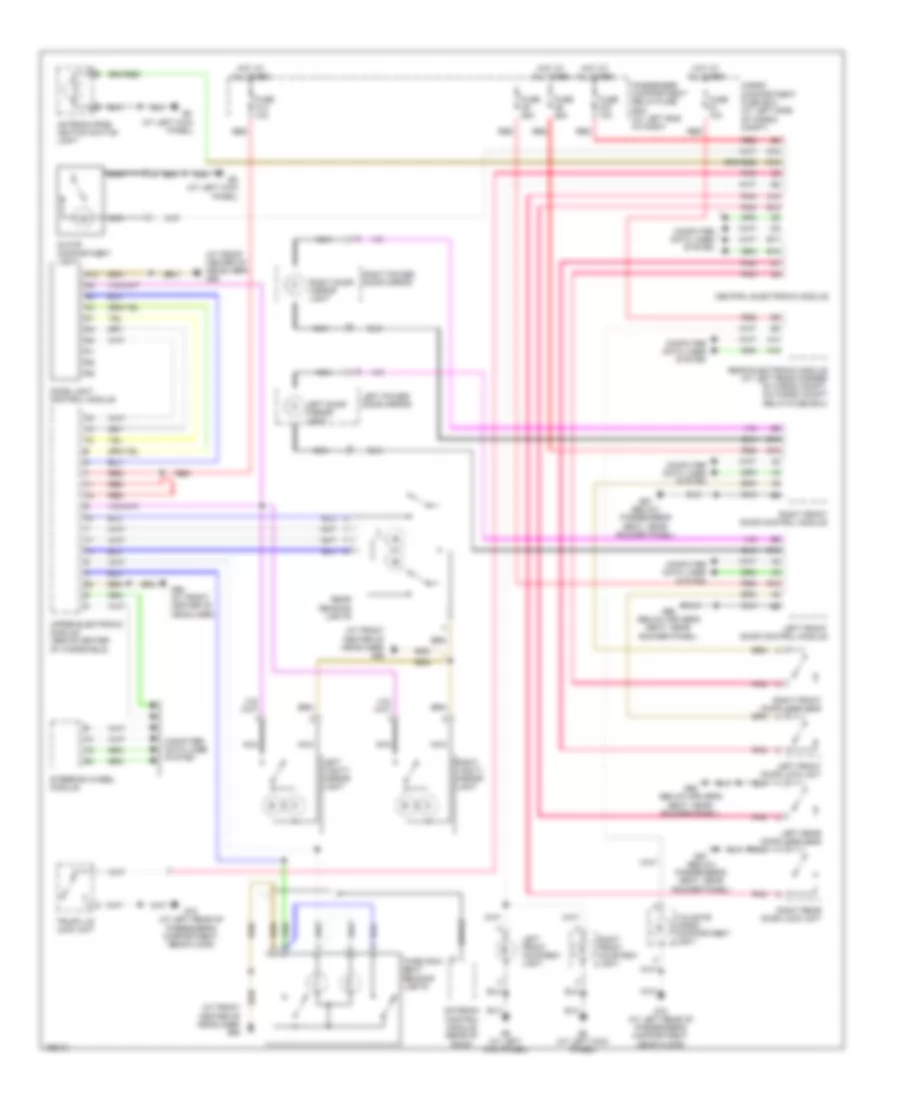
INTERIOR LIGHTS
Courtesy Lamps Wiring Diagram for Volvo XC90 2004
List of elements for Courtesy Lamps Wiring Diagram for Volvo XC90 2004:
- (at front center of headliner) g98
- (at left kick panel)
- A10
- A14
- A16
- Antenna control module (rear of roof)
- Antenna ring/ ignition switch light
- B10
- B12
- B17
- B18
- C18
- Cargo compartment fuse box (at left side of cargo compt)
- Center of headliner) g98
- Central electronic module
- Computer data lines system
- D18
- D19
- Dome light control module
- Fuse c14 10a
- Fuse c27 10a
- Fuse c5 25a
- Fuse c6 25a
- Fuse d1 10a
- G6 (at left kick panel)
- G66 (below driver's seat, near rocker panel)
- G67 (below passenger's seat, near rocker panel)
- G72 (at left rear of passenger's compartment, near floor)
- G98 (at front center of headliner)
- Glove compartment light
- Hot at all times
- Left door mirror light
- Left front courtesy light
- Left front door control module
- Left front door lock unit
- Left power door mirror
- Left rear door lock unit
- Left vanity mirror light
- Nca
- Passenger compartment relay/fuse box (at left end of dash)
- Pnk
- Rear electronic module (at left rear corner of cargo compt, on cargo compt relay/fuse box)
- Rear reading lights
- Red
- Right door mirror light
- Right front courtesy light
- Right front door control module
- Right front door lock unit
- Right power door mirror
- Right rear door lock unit
- Right vanity mirror light
- Shield
- Steering wheel module
- Tailgate cargo compartment light
- Third row seat reading lights
- Trunk lid lock unit
- Upper electronic module (above center of windshield)
Instrument Illumination Wiring Diagram for Volvo XC90 2004
List of elements for Instrument Illumination Wiring Diagram for Volvo XC90 2004:
- (at right kick panel)
- (v70, xc70) a7
- (v70,xc70) (xc90)
- (xc90) d2
- A/c climate control switch
- A11
- A12
- A13
- A14
- A16
- A18
- Audio module (under right front seat)
- Audio/cellular phone switch
- Auto
- Auto climate control switch
- Auxiliary light switch
- B17
- B18
- Central electronic module
- Climate control lighting
- Climate control module
- Combined instrument panel
- Combustion preheater module
- Compartment fan potentiometer lighting
- Computer data lines system
- Contact reel
- Cruise control switch
- Defr
- Defroster climate control switch
- Dome light control module
- Extended d1 feed relay
- Fan switch
- Floor
- Floor climate control switch
- Front cigarette lighter 12v outlet
- Fuse c23 c22 5a
- Fuse c24 c21 10a
- Fuse c32 c27 10a
- Fuse c37 c7 30a
- G66 (below driver's seat, near rocker panel)
- G67 (below passenger's seat, near rocker panel)
- G84
- Heated rear window/door mirrors switch
- Heated rear window/mirrors/ front seats lighting switches
- Hot at all times
- Left heated control lighting
- Left rear door power window switch
- Left seat heated switch
- Left side temperature switch
- Light switch module
- Max defroster switch
- Nca
- Passenger compartment relat/fuse box (at left end of dash)
- Power child lock switch (pcl)
- Power sun roof switch
- Rear adjustable head restraint
- Rear door power window child lock relay
- Rec
- Recirculation a/c light
- Recirculation switch
- Red
- Reduced alarm switch
- Retractable door mirrors switch
- Right heated control lighting
- Right rear door power window switch
- Right seat heated switch
- Right side temperature switch
- Spin control switch
- Steering wheel module
- Sunroof control module (forward of sun roof opening)
- Trunk lid/ private lock switch
- Upper electronic module (above center of windshield)
- Vent
- Ventilation climate control switch
MEMORY SYSTEMS
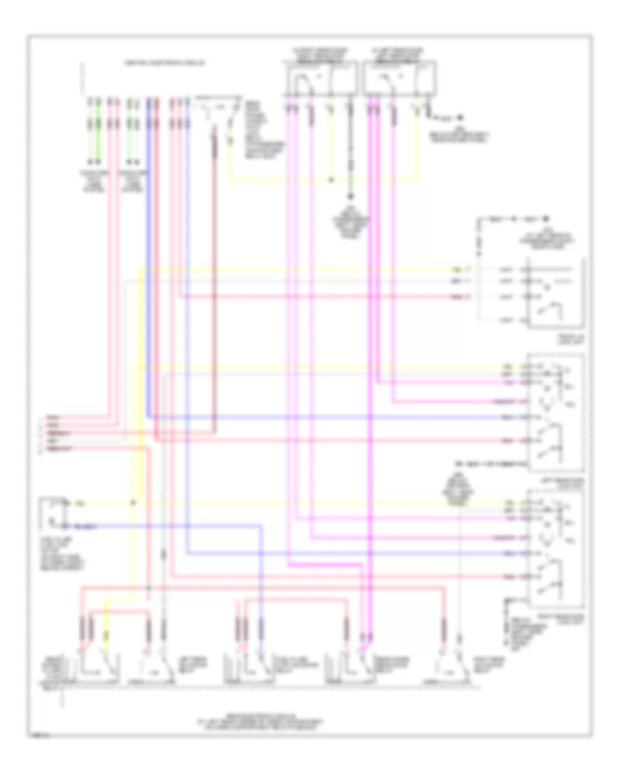
Driver"s Memory Seat Wiring Diagram for Volvo XC90 2004
List of elements for Driver"s Memory Seat Wiring Diagram for Volvo XC90 2004:
- (v70/xc70) (xc90)
- B17
- B18
- Back
- Backrest switch
- C10
- C11
- C12
- C13
- C14
- C15
- C16
- Central electronic module
- Computer data lines system
- Down
- Driver's seat backrest support motor
- Driver's seat forward/ rearward motor
- Driver's seat front edge up/down motor
- Driver's seat rear edge up/down motor
- Driver's side power seat module (under driver's seat)
- Driver's side power seat switch
- E10
- E11
- E12
- Extended d1-feed relay (in passenger compt relay box)
- Forw
- Forward/ rearward switch
- Front edge up/down switch
- Fuse c24 c21 10a
- Fuse c3 30a
- G66 (below driver's seat, near rocker panel)
- Hot at all times
- Nca
- Passenger compartment relay/fuse box (at left end of dash)
- Position
- Position 1
- Position 2
- Position 3
- Rear edge up/down switch
- Rearw
- Red
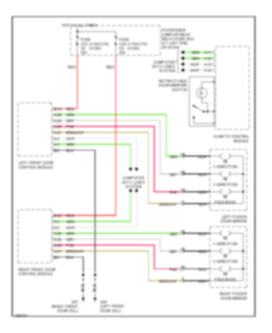
Memory Mirrors Wiring Diagram for Volvo XC90 2004
List of elements for Memory Mirrors Wiring Diagram for Volvo XC90 2004:
- (xc90) (v70/xc70)
- A10
- A11
- A12
- A13
- A14
- A25
- A26
- A27
- A28
- A29
- B12
- Climate control module
- Computer data lines system
- Fold-back
- Fuse c5 c35 25a
- Fuse c6 c36 25a
- G66 (below driver's seat, near rocker panel.)
- G67 (below passenger's seat, near rocker panel)
- Hot at all times
- Left front door control module
- Left power door mirror
- Nca
- Passenger compartment relay/fuse box (at left end of dash)
- Pnk
- Red
- Retractable door mirrors switch
- Right front door control module
- Right power door mirror
- X-direction
- Y-direction
NAVIGATION
Navigation Wiring Diagram for Volvo XC90 2004
List of elements for Navigation Wiring Diagram for Volvo XC90 2004:
- A10
- Antenna control module (rear of roof)
- Audio module (under right front seat)
- B10
- B17
- B18
- Cd control module
- Central electronic module
- Com- puter data lines system
- Computer data lines system
- Fuse c20 25a
- Fuse c37 10a
- G83 (at left kick panel)
- G84 (at right kick panel)
- Hot at all times
- Infotainment control module
- Infotainment relay (in passenger compt relay box)
- Md control module
- Multimedia display
- Multimedia module (under left front seat)
- Passenger compartment relay/fuse box (at left end of dash)
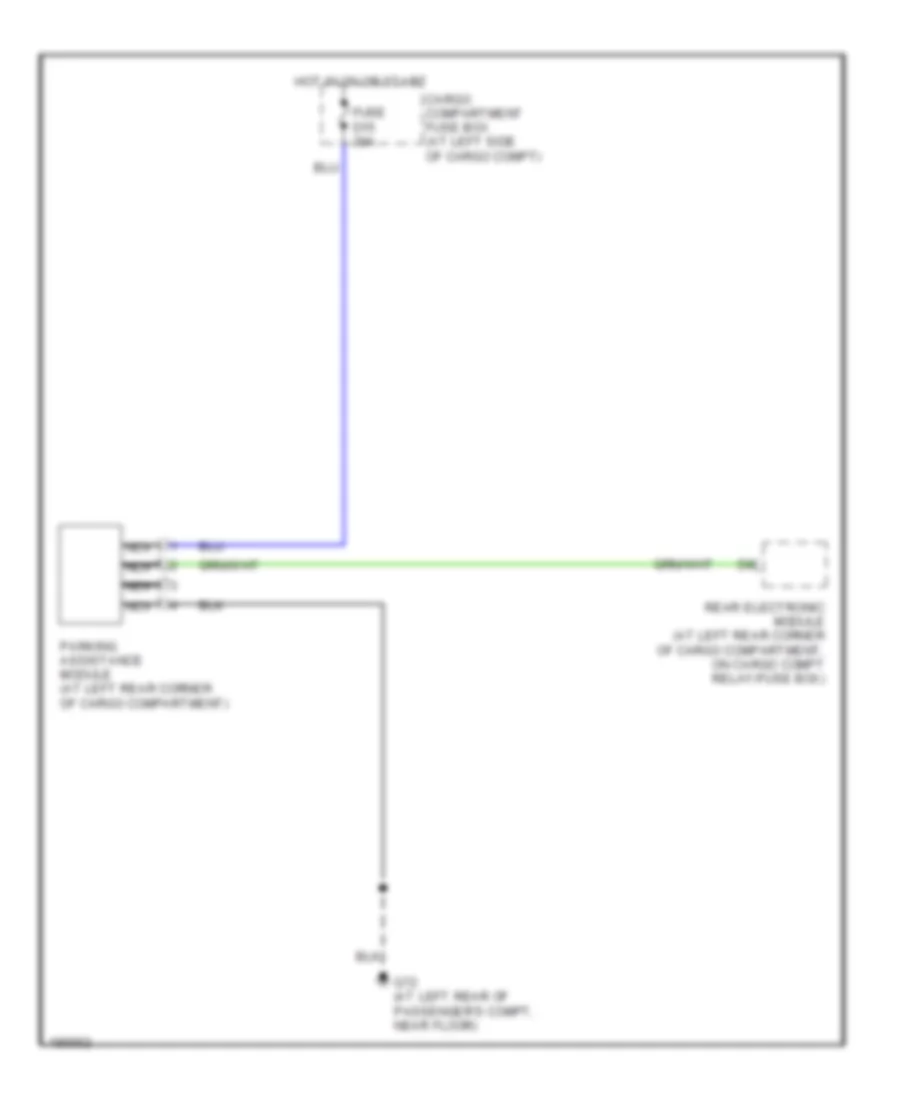
Parking Assistant Wiring Diagram for Volvo XC90 2004
List of elements for Parking Assistant Wiring Diagram for Volvo XC90 2004:
- Cargo compartment fuse box (at left side of cargo compt)
- Fuse d15 20a
- G72 (at left rear of passenger's compt, near floor)
- Hot in on or start
- Nca
- Parking assistance module (at left rear corner of cargo compartment)
- Rear electronic module (at left rear corner of cargo compartment, on cargo compt relay/fuse box)
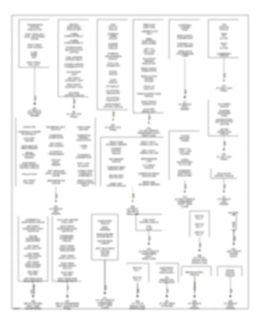
POWER DISTRIBUTION
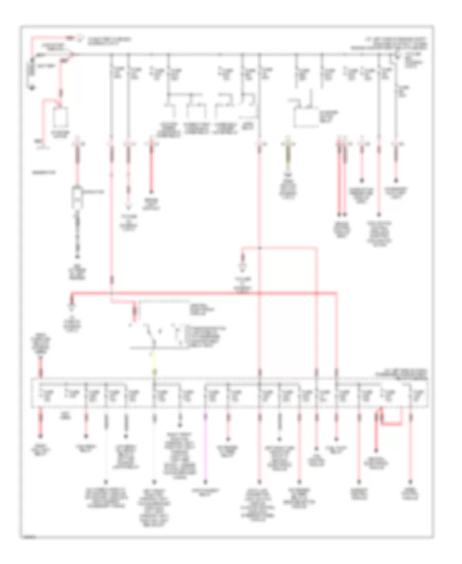
Power Distribution Wiring Diagram (1 of 3) for Volvo XC90 2004
List of elements for Power Distribution Wiring Diagram (1 of 3) for Volvo XC90 2004:
- (at left end of dash) passenger compartment relay/fuse box
- (at left side of engine compt, forward of strut tower) engine compartment relay/fuse box
- (not used)
- Accessory (auxiliary light)
- Battery
- Brake control module (bcm)
- Brake light contact
- Capacitor
- Central electronic module
- Combustion preheater module (cpm)
- Cooling fan control module & electric cooling fan motor
- Data link connector, light switch module. climate control module & steering wheel module
- Extended d1 feed relay
- Extended d2 feed relay & gear selector module
- Fan control module
- From ignition switch (diagram 3 of 3)
- From overload relays (diagram 3 of 3)
- Front fog light relay
- Fuel pump relay
- Fuse a2 60a
- Fuse a3 60a
- Fuse a4 60a
- Fuse a8 80a
- Fuse b1 25a
- Fuse b12 5a
- Fuse b13 25a
- Fuse b14 30a
- Fuse b16 15a
- Fuse b19 30a
- Fuse b2 20a
- Fuse b22 25a
- Fuse b9 15a
- Fuse c1 30a
- Fuse c20 10a
- Fuse c21 10a
- Fuse c22 5a
- Fuse c23 20a
- Fuse c24 10a
- Fuse c25 15a
- Fuse c26 15a
- Fuse c27 10a
- Fuse c28 5a
- Fuse c32 7.5a
- Fuse c33 7.5a
- Fuse c34 15a
- Fuse c35
- Fuse c36 20a
- Fuse c37 10a
- Fuse c38 15a
- G93 (at rear of left fender)
- Generator
- High beam relay
- Horn relay
- Infotainment relay
- Intermittent windshield wiper relay
- Jump start terminal
- Left front position/ parking light, towing bracket module & tail light/ parking light/ position light rem shunt
- Left/right cem indicator shunt &
- Low beam/ bl-xenon relay & daytime running lights relay
- Low/high speed windshield wiper relay
- Multimedia display, md control module, cd control module & infotainment accessory wiring
- Parking/position lights relay (in passenger compartment relay box)
- Red
- Right front position/ parking light, position light/ parking light/tail light rem shunt, license plate lights & towing bracket wiring
- Siren control module
- Starter motor
- Starter motor relay
- Sunroof control module
- To battery fuse box (diagram 2 of 3)
- To fuse b23 (diagram 2 of 3)
- To fuse c1 (diagram 3 of 3)
- To fuse c3 (diagram 3 of 3)
- To fuse c5 (diagram 3 of 3)
- Windshield washer motor relay
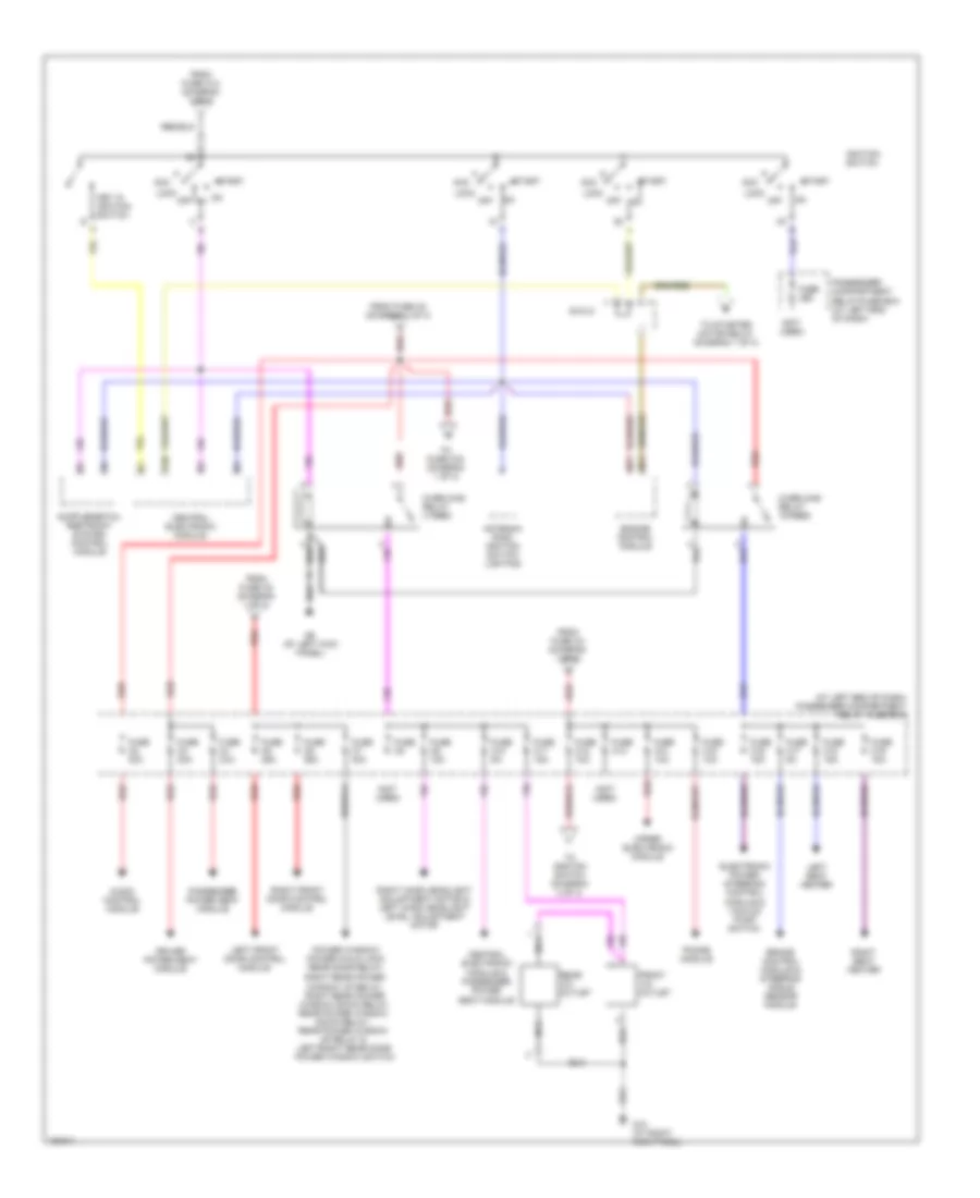
Power Distribution Wiring Diagram (2 of 3) for Volvo XC90 2004
List of elements for Power Distribution Wiring Diagram (2 of 3) for Volvo XC90 2004:
- (at left side of engine compartment, forward of strut tower) engine compartment relay/fuse box
- (not used)
- A red
- Accelerator pedal sensor, electrics box & cooling fan
- Accessory electronic module
- Antenna control module
- Bass speaker system relay
- Brake light relay & brake light rem shunt
- Cargo compartment 12v outlet
- Cargo compartment 12v outlet shunt
- Cargo compartment fuse box (at left side of cargo compt)
- Climate control system relay
- D18
- Differential electronic module
- Engine compartment cooling fan electrics box
- Engine control module
- Engine control module, fuel injectors & mass airflow sensor
- Engine management system main relay
- Evap valve, air preheating ptc resistor, turbocharger control valve, variable valve timing inlet solenoid & variable valve timing outlet solenoid
- From b fuse b2 (diagram 1 of 3)
- From battery (diagram 1 of 3)
- From fuse d5 (diagram 2 of 3)
- Fuel leakage control pump
- Fuse a1 60a
- Fuse b10 10a
- Fuse b11 20a
- Fuse b15 25a
- Fuse b23 5a
- Fuse b3
- Fuse b4 20a
- Fuse b5 10a
- Fuse b6 15a
- Fuse b8 10a
- Fuse d1 10a
- Fuse d10 5a
- Fuse d11 15a
- Fuse d12 15a
- Fuse d13 15a
- Fuse d15 20a
- Fuse d16
- Fuse d17 7.5a
- Fuse d2 10a
- Fuse d3 15a
- Fuse d4 10a
- Fuse d5 5a
- Fuse d6 10a
- Fuse d7 15a
- Fuse d8 20a
- Fuse d9 15a
- Fuse e1 40a
- Fuse e2 40a
- Fuse e3 40a
- Fuse e4
- Fuse e5 40a
- Fuse e6
- Fuse e7 40a
- G73 (at right rear of passenger's compt, near floor)
- Glow plug unit relay
- Heated oxygen sensors
- Heated rear window relay
- High pressure wash relay
- Intermittent rear window wiper on/off relay
- Left/right rear door deadlock relay, filler flap/rear doors locking relay, fuel filler flap unlocking relay, left/right rear door locking/unlocking relay & rear door deadlock relay
- Main fuses (next to battery, in cargo compartment)
- Parking assistance module & towing bracket wiring
- Rear accessory relay (15 feed)
- Rear climate control system relay
- Rear electrical module
- Rear electronic module
- Rear electronic module (rem)
- Rear window washer motor relay
- Rear window wiper relay
- Red
- Reversing light relay
- Spark plug & ignition coil, egr valve, engine mounting solenoid valve & variable turbo geometry solenoid
- Tailgate unlocking relay
- To rear accessory relay (diagram) 2 of 3
- Towing bracket wiring
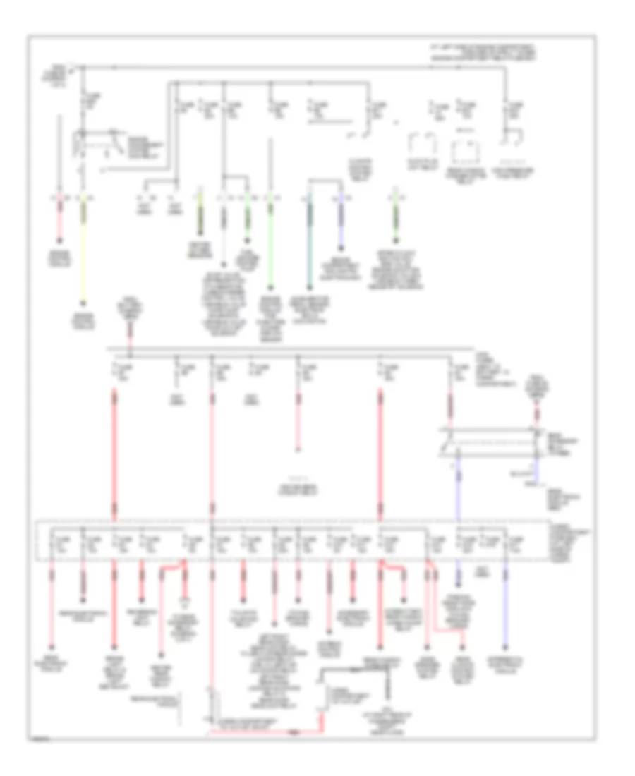
Power Distribution Wiring Diagram (3 of 3) for Volvo XC90 2004
List of elements for Power Distribution Wiring Diagram (3 of 3) for Volvo XC90 2004:
- (at left end of dash) passenger compartment relay/ fuse box
- (not used)
- 15i
- 54/3lc
- Acc
- Antenna ring/ ignition switch lighting
- Audio control module
- Brake control module & steering angle sensor module
- Central electronic module
- Central electronic module & passenger power seat module
- Driver power seat module
- Electronic power steering control module & vacuum pump switch
- Engine control module
- From fuse a2 (diagram 1 of 3)
- From fuse a3 (diagram 1 of 3)
- From fuse a4 (diagram 1 of 3)
- From fuse c12 (diagram 1 of 3)
- Front 12v outlet
- Fuse c10 5a
- Fuse c11 15a
- Fuse c12 10a
- Fuse c13
- Fuse c14 10a
- Fuse c15 10a
- Fuse c16 15a
- Fuse c17 5a
- Fuse c18 15a
- Fuse c19 15a
- Fuse c2 30a
- Fuse c29
- Fuse c3 30a
- Fuse c4 30a
- Fuse c5 25a
- Fuse c6 25a
- Fuse c7 30a
- Fuse c8
- Fuse c9 15a
- G10 (at right kick panel)
- G6 (at left kick panel)
- Ignition switch
- Key in ignition switch
- Left front door control module
- Left seat heater
- Lock
- Nca
- Off
- Off on
- Overload relay 15-feed
- Overload relay x feed
- Passenger compartment relay/fuse box (at left end of dash)
- Passenger power seat module
- Phone module
- Power window/ power child lock rear door relay,
- Rear 12v outlet
- Red
- Right front door control module
- Right hand headlight adjustment motor & left hand headlight level adjustment motor
- Right rear power window up relay, right rear power window down relay, rear power window down relay, rear power window up relay & left/right rear door power window switch
- Right seat heater
- Start
- To fuse c34 (diagram 1 of 3)
- To ignition switch (diagram 3 of 3)
- To starter motor relay (diagram 1 of 3)
- Upper electronic module
POWER DOOR LOCKS
Power Door Locks Wiring Diagram (1 of 2) for Volvo XC90 2004
List of elements for Power Door Locks Wiring Diagram (1 of 2) for Volvo XC90 2004:
- A11
- A12
- A13
- A14
- A16
- B12
- Bll
- Cargo compartment fuse box (at left side of cargo compt)
- Climate control module
- Combination instrument panel
- Compartment relay/fuse box)
- Computer data lines system
- Fuse c5 25a
- Fuse c6 25a
- Fuse c7 30a
- Fuse d6 10a
- Fuse d8 20a
- G66 (below driver's seat, near rocker panel)
- G67 (below passenger's seat, near rocker panel)
- Hot at all times
- Key
- Left front door control module
- Left front door lock unit
- Lock
- Passenger compartment relay/fuse box (at left end of dash)
- Pnk
- Power child lock switch
- Rear electronic module (at left rear corner of cargo compartment, on cargo
- Red
- Right front door control module
- Right front door lock unit
- Tailgate unlocking relay (in cargo compartment relay/fuse box)
- Trunk lid private lock switch
- Unlock
- Upper electronic module (above center of windshield)
Power Door Locks Wiring Diagram (2 of 2) for Volvo XC90 2004
List of elements for Power Door Locks Wiring Diagram (2 of 2) for Volvo XC90 2004:
- (below passenger's seat, near rocker panel) g67
- (in left rear door) left rear door deadlock relay
- (in right rear door) right rear door deadlock relay
- B12
- B13
- B17
- B18
- Bll
- C18
- Central electronic module
- Computer data lines system
- Fuel filler flap lock motor (on right side of cargo compt, behind carpet)
- Fuel filler flap unlocking relay
- G66 (below driver's seat, near rocker panel)
- G67 (below passenger's seat, near rocker panel)
- G72 (at left rear of passenger's compt, near floor)
- Left rear door lock unit
- Left rear unlocking relay
- Pcl
- Pnk
- Rear door power window child lock relay (in passenger compartment relay box)
- Rear doors deadlocks relay
- Rear doors filler flap locking relay
- Rear electronic module (at left rear corner of cargo compartment, on cargo compartment relay/fuse box)
- Right rear door lock unit
- Right rear unlocking relay
- Trunk lid lock unit
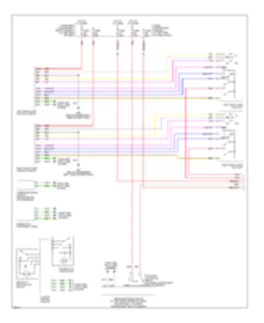
POWER MIRRORS
Power Mirrors Wiring Diagram for Volvo XC90 2004
List of elements for Power Mirrors Wiring Diagram for Volvo XC90 2004:
- (v70/xc70) (xc90)
- A11
- A12
- A13
- A14
- A26
- A27
- A28
- A29
- B12
- Climate control module
- Computer data lines system
- Fold-back
- Fuse c35 c5 25a
- Fuse c36 c6 25a
- G66 (left front door sill)
- G67 (right front door sill)
- Hot at all times
- Left front door control module
- Left power door mirror
- Nca
- Passenger compartment relay/fuse box (at left end of dash)
- Pnk
- Red
- Retractable door mirrors switch
- Right front door control module
- Right power door mirror
- X-direction
- Y-direction
POWER SEATS
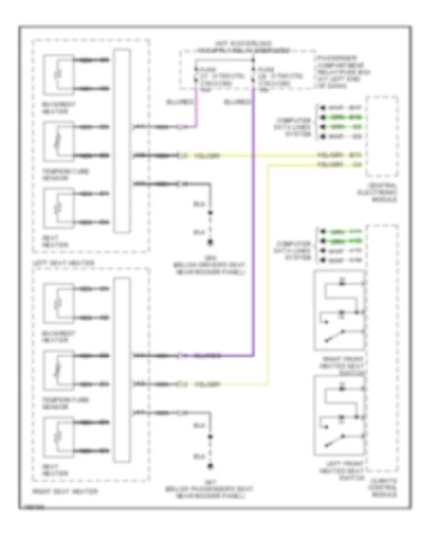
Heated Seats Wiring Diagram for Volvo XC90 2004
List of elements for Heated Seats Wiring Diagram for Volvo XC90 2004:
- (v70/xc70) (xc90)
- A11
- A12
- A13
- A14
- B11
- B17
- B18
- Backrest heater
- Central electronic module
- Climate control module
- Computer data lines system
- Fuse c7 c18 15a
- Fuse c8 c19 15a
- G66 (below driver's seat, near rocker panel)
- G67 (below passenger's seat, near rocker panel)
- Left front heated seat switch
- Left seat heater
- Nca
- Passenger compartment relay/fuse box (at left end of dash)
- Right front heated seat switch
- Right seat heater
- Seat heater
- Temperature sensor
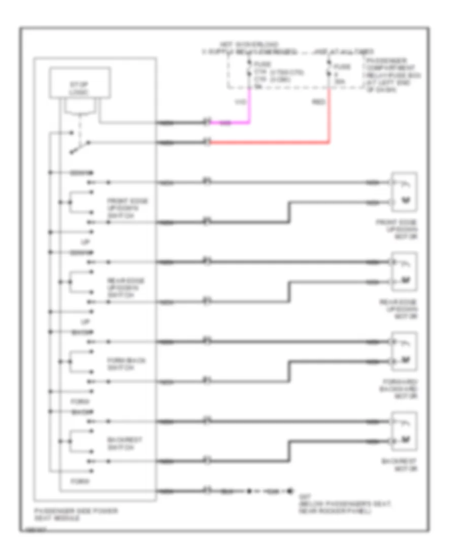
Passenger"s Power Seat Wiring Diagram for Volvo XC90 2004
List of elements for Passenger"s Power Seat Wiring Diagram for Volvo XC90 2004:
- (v70/xc70) (xc90)
- Back
- Backrest motor
- Backrest switch
- Down
- Forw
- Forw/back switch
- Forward/ backward motor
- Front edge up/down motor
- Front edge up/down switch
- Fuse 30a
- Fuse c14 c10 5a
- G67 (below passenger's seat, near rocker panel)
- Hot at all times
- Nca
- Passenger compartment relay/fuse box (at left end of dash)
- Passenger side power seat module
- Rear edge up/down motor
- Rear edge up/down switch
- Red
- Stop logic
POWER TOP/SUNROOF
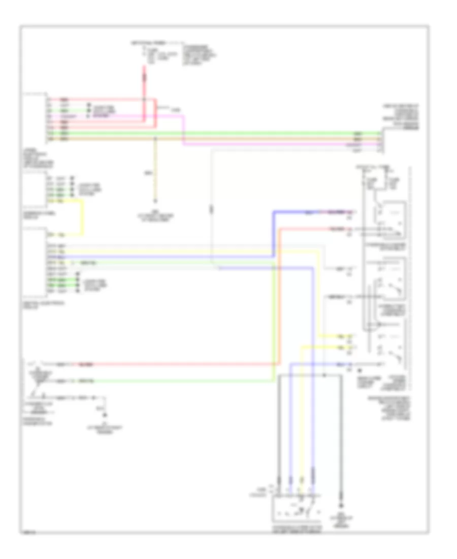
Sunroof Wiring Diagram for Volvo XC90 2004
List of elements for Sunroof Wiring Diagram for Volvo XC90 2004:
- (v70/xc70) (xc90)
- Bwd
- Computer data lines system
- Dome light control module
- Fuse c34 c26 15a
- Fwd
- G6 (at left kick panel)
- G98 (at front center of headliner)
- Hot at all times
- Nca
- Passenger compartment relay/fuse box (at left end of dash)
- Pnk
- Power sun roof switch
- Red
- Solid state
- Sun roof control module (forward of sun roof opening)
- Sun roof motor (forward of sun roof opening)
- Upper electronic module (above center of windshield)
POWER WINDOWS
Power Windows Wiring Diagram for Volvo XC90 2004
List of elements for Power Windows Wiring Diagram for Volvo XC90 2004:
- (below driver's seat, near rocker panel) g66
- (below passenger's seat, near rocker panel) g67
- (v70/xc70) (xc90)
- A16
- A19
- A23
- A24
- B12
- B17
- B18
- Central electronic module
- Computer data lines system
- Fuse c35 c5 25a
- Fuse c36 c6 25a
- Fuse c37 c7 30a
- G66 (below driver's seat, near rocker panel)
- G67 (below passenger's seat, near rocker panel)
- Hot at all times
- Left front door control module
- Left front power window motor
- Left rear door power window switch
- Left rear power window down relay
- Left rear power window motor
- Left rear power window up relay
- Passenger compartment fuse box (at left end of dash)
- Rear doors power window child lock relay
- Red
- Right front door control module
- Right front power window motor
- Right rear door power window switch
- Right rear power window down relay
- Right rear power window motor
- Right rear power window up relay
- Solid state
RADIO
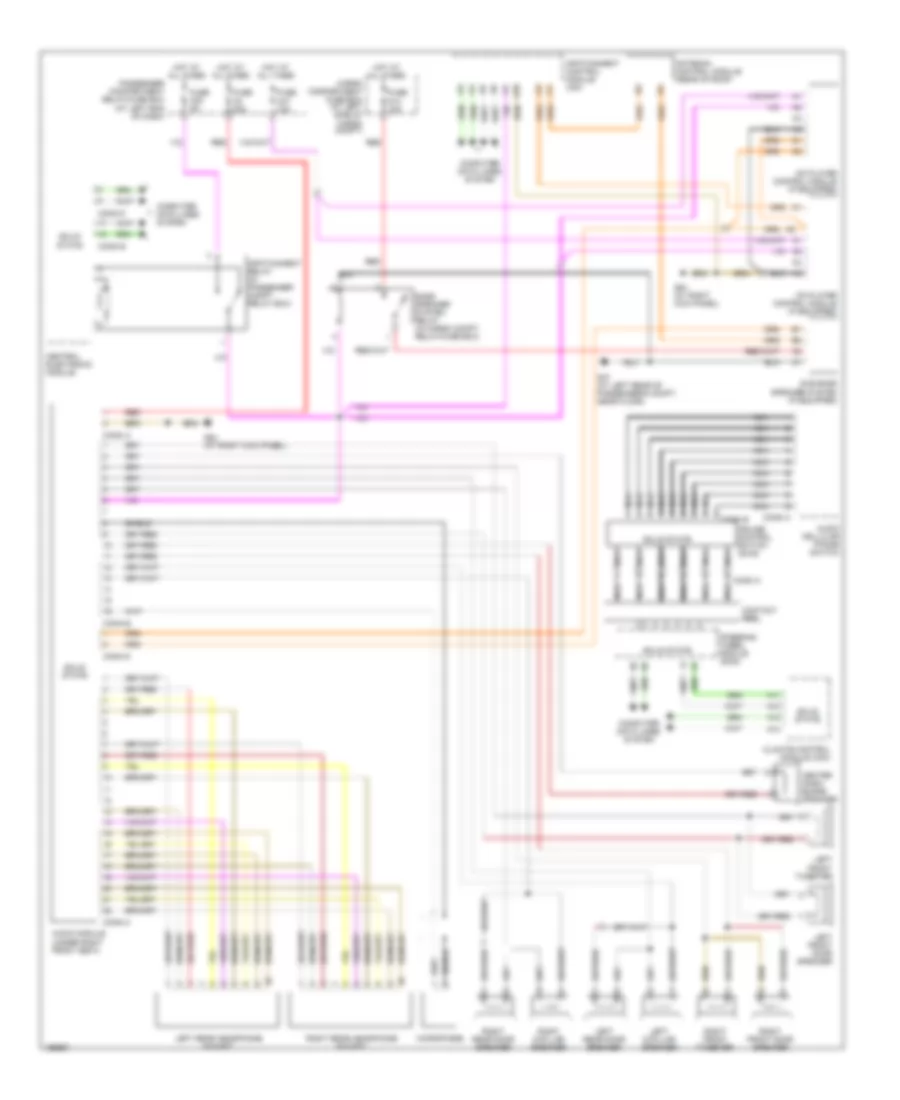
Radio Wiring Diagram for Volvo XC90 2004
List of elements for Radio Wiring Diagram for Volvo XC90 2004:
- (at left end of dash)
- A10
- A11
- A12
- A13
- A14
- Antenna control module (rear of roof)
- Audio cellular phone switch
- Audio module (under right front seat)
- Bass speaker system relay (in cargo compt, relay/fuse box)
- Cargo compartment fuse box (at left side of cargo compt)
- Cd player control module (if equipped)
- Center dash- board speaker
- Central electronic module
- Climate control module (ccm)
- Computer data lines system
- Conn a
- Conn b
- Conn c
- Conn d
- Contact reel
- Cruise control switch (sws)
- Fuse c2 30a
- Fuse c20 5a
- Fuse c37 10a
- Fuse d13 15a
- G47 (at left rear of passenger's compt, near floor)
- G84 (at right kick panel)
- Hot at all times
- Infotainment control module (icm)
- Infotainment relay (in passenger compt relay box)
- Left d-pillar speaker
- Left front door speaker
- Left front tweeter
- Left rear door speaker
- Left rear headphone socket
- Md player control module (if equipped)
- Microphone
- Nca
- Passenger compartment relay/fuse box
- Red
- Right d-pillar speaker
- Right front door speaker
- Right front tweeter
- Right rear door speaker
- Right rear headphone socket
- Shield
- Solid state
- Steering wheel module (swm)
- Sub bass speaker system (if equipped)
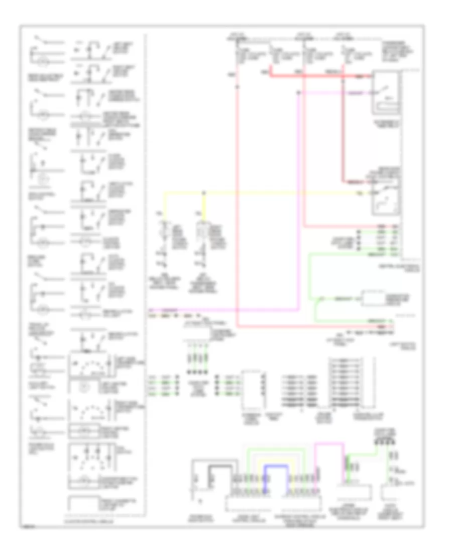
SHIFT INTERLOCK
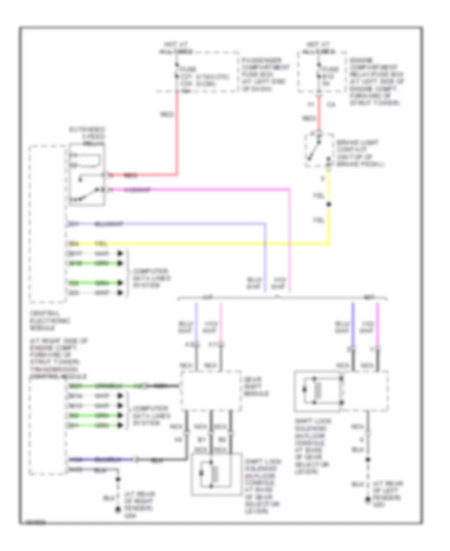
Shift Interlock Wiring Diagram for Volvo XC90 2004
List of elements for Shift Interlock Wiring Diagram for Volvo XC90 2004:
- (at rear of left fender) g93
- (at rear of right fender) g94
- (at right side of engine compt, forward of strut tower) transmission control module
- (in floor console, at base of gear selector lever)
- (v70/xc70) (xc90)
- A/t
- A53
- A54
- B13
- B14
- B17
- B18
- B21
- Brake light contact (on top of brake pedal)
- Central electronic module
- Computer data lines system
- Engine compartment relay/fuse box (at left side of engine compt, forward of strut tower)
- Extended x-feed relay
- Fuse b12 5a
- Fuse c21 c24 10a
- Gear shift module
- Hot at all times
- M/t
- Nca
- Passenger compartment fuse box (at left end of dash)
- Red
- Shift lock solenoid
- Shift lock solenoid (in floor console, at base of gear selector lever)
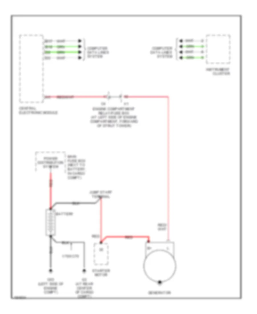
STARTING/CHARGING
Charging Wiring Diagram for Volvo XC90 2004
List of elements for Charging Wiring Diagram for Volvo XC90 2004:
- B17
- B18
- Battery
- Central electronic module
- Computer data lines system
- Engine compartment relay/fuse box (at left side of engine compartment, forward of strut tower)
- G3 (at rear center of cargo compt)
- G53 (left side of engine compt)
- Generator
- Instrument cluster
- Jump start terminal
- Main fuse box (next to battery, in cargo compt)
- Power distribution system
- Red
- Starter motor
- V70/xc70
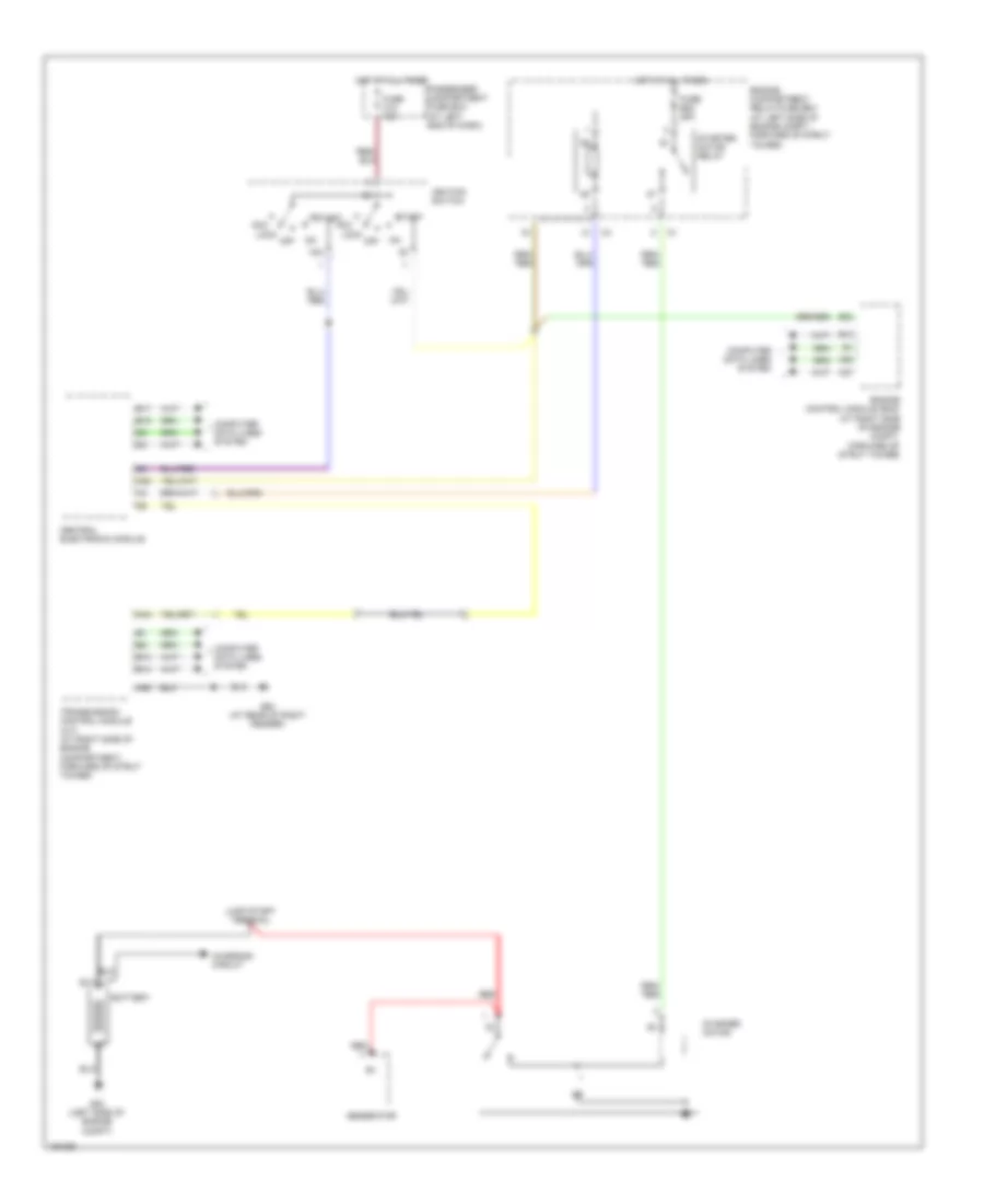
Starting Wiring Diagram for Volvo XC90 2004
List of elements for Starting Wiring Diagram for Volvo XC90 2004:
- 15a
- A20
- A37
- A44
- A53
- A55
- Acc
- B13
- B14
- B17
- B18
- B23
- Battery
- Central electronic module
- Charging circuit
- Computer data lines system
- Engine compartment relay/fuse box (at left side of engine compt, forward of strut tower)
- Engine control module (ecm) (at right side of engine compt, forward of strut tower)
- Fuse b22 25a
- Fuse c12 10a
- G53 (left side of engine compt)
- G94 (at rear of right fender)
- Generator
- Hot at all times
- Ignition switch
- Jump start terminal
- Lock
- Off
- Passenger compartment fuse box (at left end of dash)
- Red
- Start
- Starter motor
- Starter motor relay
- Transmission control module (a/t) (at right side of engine compartment, forward of strut tower)
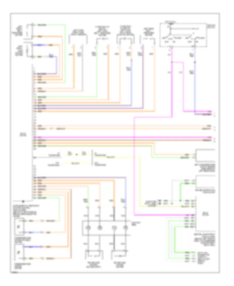
SUPPLEMENTAL RESTRAINTS
Supplemental Restraints Wiring Diagram (1 of 2) for Volvo XC90 2004
List of elements for Supplemental Restraints Wiring Diagram (1 of 2) for Volvo XC90 2004:
- (third row of seats) left hand belt tensioner igniter
- (third row of seats) left hand inflatable curtain igniter
- Acc
- B19
- B20
- Central electronic module (cem) (behind left side of dash, on passenger compartment relay box)
- Computer data lines system
- Contact reel
- Data link connector (partial) (below left side of dash)
- Driver information module (dim)
- Driver side air bag igniter
- Driver side air bag igniter step 2
- Hot at all times
- Ignition switch
- Left front belt tensioner igniter
- Left front side air bag igniter
- Left rear belt tensioner igniter
- Left-hand front side impact sensor
- Left-hand rear side impact sensor (near rear of left rear door)
- Nca
- Off
- Passenger side air bag igniter
- Passenger side air bag stage 2 igniter
- Solid state
- Start
- W/ telephone
- W/o telephone
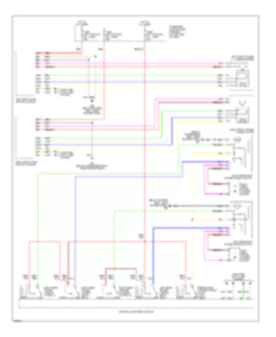
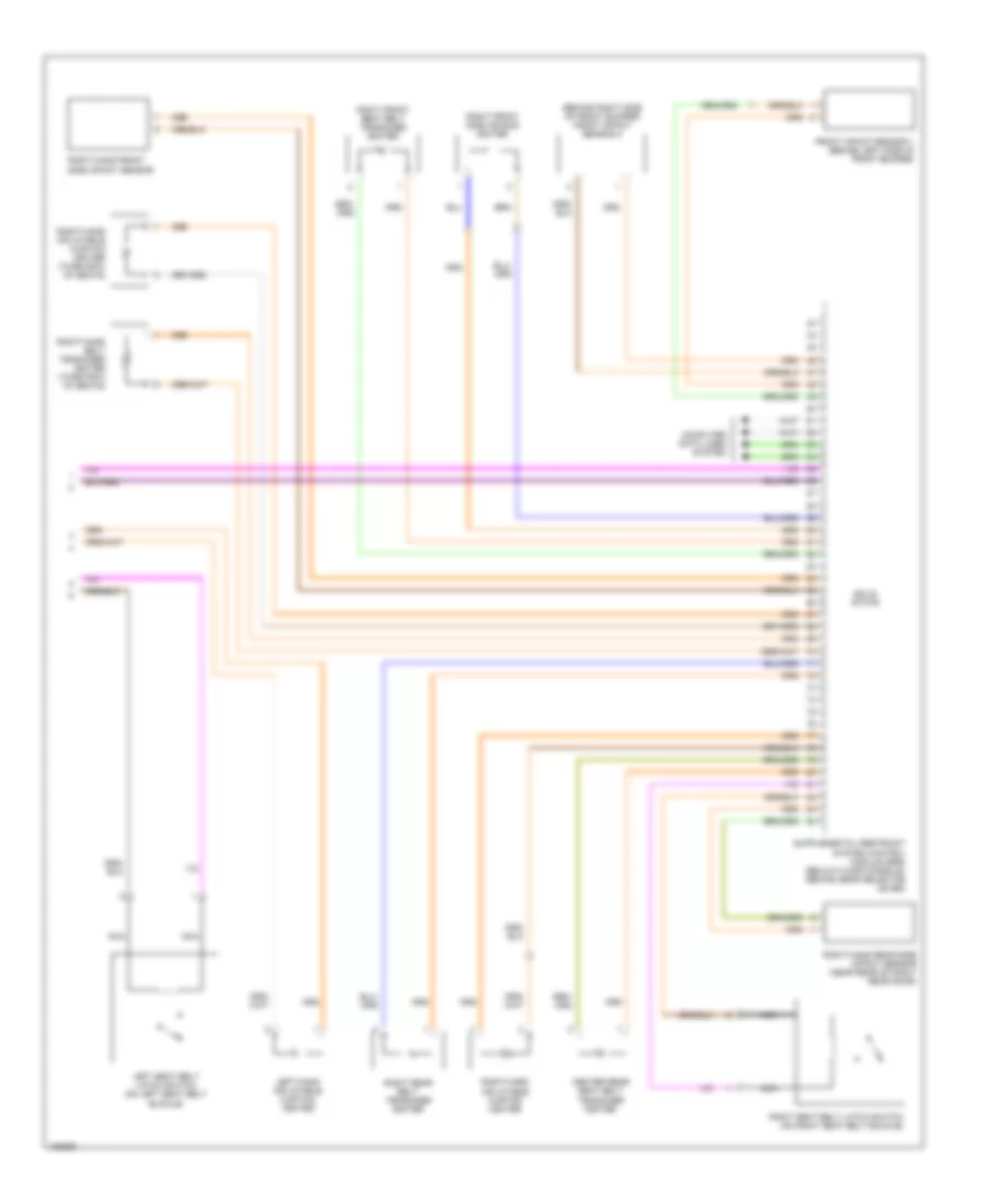
Supplemental Restraints Wiring Diagram (2 of 2) for Volvo XC90 2004
List of elements for Supplemental Restraints Wiring Diagram (2 of 2) for Volvo XC90 2004:
- (behind right side of front bumper) front impact sensor 2
- Center rear seat belt tensioner igniter
- Computer data lines system
- Front impact sensor 1 (behind left side of front bumper)
- Left seat belt latch switch (on left seat belt buckle)
- Left-hand inflatable curtain igniter
- Nca
- Right front seat belt tensioner igniter
- Right front side air bag igniter
- Right rear belt tensioner igniter
- Right seat belt latch switch (on right seat belt buckle)
- Right-hand belt tensioner igniter (third row of seats)
- Right-hand front side impact sensor
- Right-hand inflatable curtain igniter
- Right-hand inflatable curtain igniter (third row of seats)
- Right-hand rear side impact sensor (near rear of right rear door)
- Solid state
TRANSMISSION
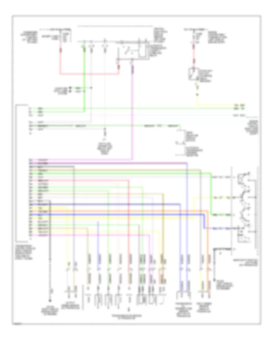
Transmission Wiring Diagram, 4T65EV for Volvo XC90 2004
List of elements for Transmission Wiring Diagram, 4T65EV for Volvo XC90 2004:
- (pins 15-20 not used)
- (pins 3-12 not used)
- (pins 42-43 not used)
- (pins 47-49 not used)
- (pins 60-62 not used)
- (pins 66-67 not used)
- Automatic transmission program selector
- B13
- B26
- C24
- Central electrical module (behind left side of dash)
- Computer data lines system
- Data link connector (below left side of dash)
- Engine compartment fuse/relay box (left side of engine compt)
- Engine control module (right side of engine compt)
- Extended d2 feed relay (a/t)
- Fuse b12 5a
- Fuse c24 10a
- G31/93 (rear of left front fender)
- G31/94 (rear of right front fender)
- Gear selector module switch
- Gear shift position switches (top right of transaxle)
- Hot at all times
- Input speed sensor (rear of transaxle)
- Nca
- Nca ot
- Nca otg
- Nca sp2+
- Nca sp2-
- Oil pressure sensor (rear of transaxle)
- Output speed sensor (right front of transaxle)
- Passenger compartment fuse box (at left end of dash)
- Red
- Sth
- Sthg
- Stoplight switch (on brake pedal bracket)
- Transmission control module (right side of engine compt, forward of strut tower)
- Transmission oil temperature sensor (bottom of transaxle)
- Transmission solenoids (in transaxle)
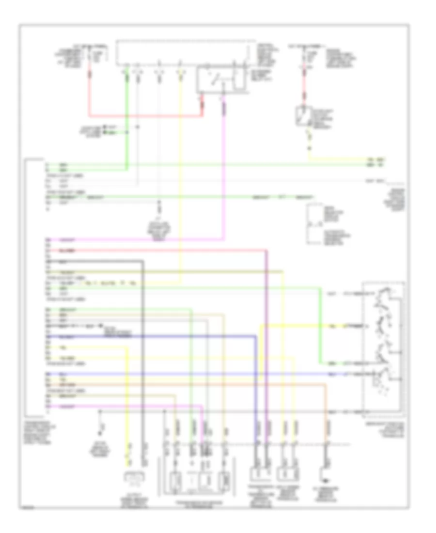
Transmission Wiring Diagram, AW55-50 for Volvo XC90 2004
List of elements for Transmission Wiring Diagram, AW55-50 for Volvo XC90 2004:
- (except xc90) (xc90)
- Automatic transmission program selector
- B13
- B26
- C24
- Central electrical module (behind left side of dash)
- Computer data lines system
- Data link connector (below left side of dash)
- Engine compartment fuse/relay box (left side of engine compt)
- Engine control module (right side of engine compt)
- Fuse b12 5a
- Fuse c21 c24 10a
- G31/93 (left side of engine compt, on fender)
- G31/94 (right side of engine compt, on fender)
- Gear selector module switch
- Gear shift position switches (on transaxle)
- Hot at all times
- Input speed sensor (rear of transaxle)
- Nca
- Output speed sensor (on transaxle)
- Passenger compartment fuse box (at left end of dash)
- Red
- Sls
- Slsg
- Slt
- Sltg
- Slu
- Slug
- Stoplight switch (on brake pedal bracket)
- Transmission control module (right side of engine compt, forward of strut tower)
- Transmission oil temperature sensor (bottom of transaxle)
- Transmission solenoids (in transaxle)
WARNING SYSTEMS
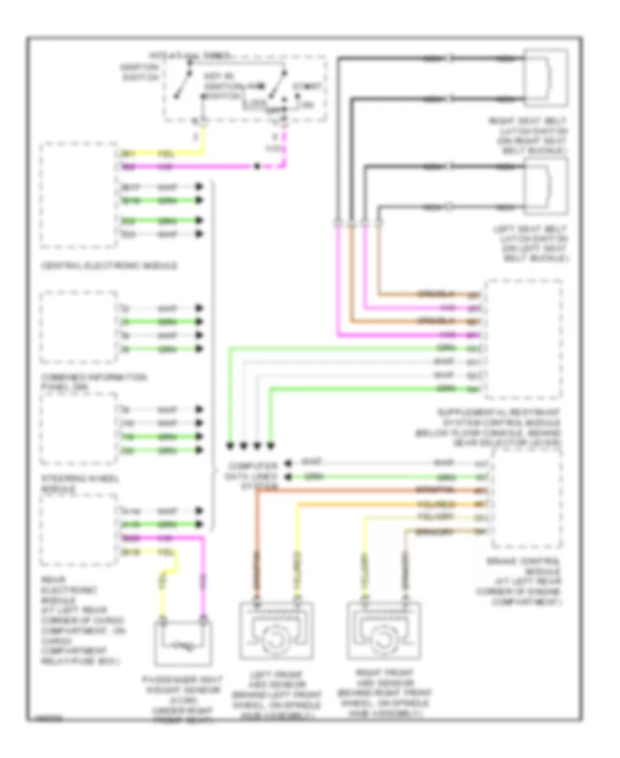
Warning Systems Wiring Diagram for Volvo XC90 2004
List of elements for Warning Systems Wiring Diagram for Volvo XC90 2004:
- A14
- A16
- Acc
- B17
- B18
- B19
- B20
- Brake control module (at left rear corner of engine compartment)
- Central electronic module
- Combined information panel dim
- Computer data lines system
- Hot at all times
- Ignition switch
- Key-in ignition switch
- Left front abs sensor (behind left front wheel, on spindle /hub assembly)
- Left seat belt latch switch (on left seat belt buckle)
- Lock off
- Nca
- Passenger seat weight sensor (xc90) (under right front seat)
- Rear electronic module (at left rear corner of cargo compartment, on cargo compartment relay/fuse box)
- Right front abs sensor (behind right front wheel, on spindle /hub assembly)
- Right seat belt latch switch (on right seat belt buckle)
- Start
- Steering wheel module
WIPER/WASHER
Front Wiper/Washer Wiring Diagram for Volvo XC90 2004
List of elements for Front Wiper/Washer Wiring Diagram for Volvo XC90 2004:
- (above center of windshield, forward of rearview mirror)
- (v70, xc70) (xc90)
- A13
- A14
- A16
- B15
- B16
- B17
- B18
- Central electronic module
- Computer data lines system
- Engine compartment relay/fuse box (left side of engine compt, forward of strut tower)
- Fuse b13 25a
- Fuse b16 15a
- Fuse c28 c14 10a
- G1 (at rear of right fender)
- G93 (at rear of left fender)
- G98 (at front center of headliner)
- Hot at all times
- Intermittent windshield wiper relay
- Low/high speed windshield wiper relay
- Nca
- Passenger compartment relay/fuse box (at left end of dash)
- Rain sensor module
- Rear wiper/ washer circuit
- Red
- Steering wheel module
- Upper electronic module (above center of windshield)
- V70/xc70
- Washer fluid level sensor
- Windshield washer motor
- Windshield washer motor relay
- Windshield washer pump
- Windshield wiper motor (on left side of plenum)
- Xc90
Headlamp Washer Wiring Diagram for Volvo XC90 2004
List of elements for Headlamp Washer Wiring Diagram for Volvo XC90 2004:
- B15
- B17
- B18
- Central electronic module
- Computer data lines system
- Engine comartment relay/fuse box (at left side of engine compt, forward of strut tower)
- Fuse b15 25a
- G1 (at rear of right fender)
- High pressure wash relay
- Hot at all times
- Nca
- Washer fluid level sensor
- Windshield washer pump
- Windshield wiper motor (on left side of plenum)
Rear Wiper/Washer Wiring Diagram for Volvo XC90 2004
List of elements for Rear Wiper/Washer Wiring Diagram for Volvo XC90 2004:
- (in cargo compartment
- A14
- A16
- A17
- B15
- B17
- B18
- Cargo compartment relay/ fuse box (at left side of cargo compt)
- Central electronic module
- Computer data lines system
- Engine compartment relay/fuse box (left side of engine compt, forward of strut tower)
- Front wiper/ washer circuit
- Fuse b10 10a
- Fuse d12 15a
- G1 (at rear of right fender)
- G72 (at left rear of passenger's compt, near floor)
- G93 (at rear of left fender)
- Hot at all times
- Intermittent rear window wiper on/off relay (in cargo compt relay/fuse box)
- Nca
- Rear electronic module (on cargo compartment relay/fuse box)
- Rear window washer motor relay
- Rear window wiper motor (at center of tailgate)
- Rear window wiper relay
- Red
- Relay/fuse box)
- Steering wheel module
- Washer fluid level sensor
- Windshield washer motor
- Windshield washer pump

 Čeština
 Dansk
Dansk Deutsch
 Ελληνικά
 English
 English
 Español
 Suomi
Suomi Français
 עברית
עברית Hrvatski
 Magyar
 Italiano
 日本語
日本語 한국어
한국어 Nederlands
 Polski
 Português
 Português
 Română
 Русский
 Slovenčina
 Slovenščina
 Svenska
 Türkçe
 中文 (中国)