HEADLIGHTS
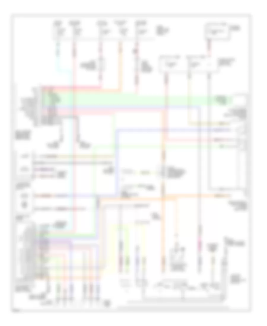
Fog Lamps Wiring Diagram for Infiniti Q45 1997


List of elements for Fog Lamps Wiring Diagram for Infiniti Q45 1997:
- 18b
- A/d gnd
- Acc
- Auto
- Auto sens 5v
- Auto sens grd
- Auto sens sig
- Batt
- Body control module (bcm) (behind left side of dash)
- Combo sw (auto)
- Exterior lights system
- Fog lamp relay (fuse, fusible link and relay box)
- Front fog lamp switch
- Fuse 14 7.5a
- Fuse 32 7.5a
- Fuse 40 15a
- Fuse 53 15a
- Fuse 54 15a
- Fuse 7.5a
- Fuse block (j/b) (left kick panel)
- Fuse link a 120a
- Fuse, fusible link and relay box
- Fusible link box
- G100 (front of left front fender)
- G201 (right end of dash)
- G202 (left end of dash)
- Gnd
- Hdlp relay
- Head
- Headlamp relay (fuse, fusible link and relay box)
- Headlights system
- Hot at all times
- Hot in accy or on
- Hot in on or start
- Ign
- Joint conn- ector 3 (left end of dash)
- Joint connector 10 (top center of dash, behind air vents)
- Joint connector 4 (top left end of dash)
- Left front fog lamp
- Lighting switch (combination switch)
- Low
- Nca
- Off
- Optical sensor (top of dash, behind combination meter)
- Park
- Pass
- Pnk
- Red
- Right front fog lamp
Headlamps Wiring Diagram, with DRL for Infiniti Q45 1997
List of elements for Headlamps Wiring Diagram, with DRL for Infiniti Q45 1997:
- 10d
- 18b
- A/d gnd
- Acc
- Alt-l
- Anti- theft system
- Auto
- Auto sens 5v
- Auto sens grd
- Auto sens sig
- Batt
- Body control module (bcm) (behind left side of dash)
- Combination meter
- Combo sw (auto)
- Diode (upper center of dash)
- Drl control unit (left front shock tower)
- Exterior lights system
- Fuse 14 7.5a
- Fuse 32 7.5a
- Fuse 53 15a
- Fuse 54 15a
- Fuse 7.5a
- Fuse block (j/b) (left kick panel)
- Fuse link a 120a
- Fuse, fusible link and relay box
- Fusible link box
- G100 (front of left front fender)
- G201 (right end of dash)
- G202 (left end of dash)
- Gnd
- Ground
- Hdlp relay
- Head
- Headlamp relay (fuse, fusible link and relay box)
- High beam ind
- Horns system
- Hot at all times
- Hot in accy or on
- Hot in on or start
- Hot in start
- Ign
- Ignition
- Illumination time control switch
- Interior lights system
- Joint conn- ector 3 (left end of dash)
- Joint connector 10 (top center of dash, behind air vents)
- Joint connector 4 (top left end of dash)
- Left headlamp
- Lft hi beam
- Lft lite
- Lft lite fus
- Lft lite hi
- Lft lite lo
- Lft lo beam
- Lighting switch (combination switch)
- Low
- Nca
- Off
- Optical sensor (top of dash, behind combination meter)
- Park
- Park brk sw
- Parking brake switch (park lever)
- Pass
- Pnk
- Red
- Right head- lamp
- Rt hi beam
- Rt lite
- Rt lite fus
- Rt lite hi
- Rt lite lo
- Rt lo beam
- Start
- Starting/ charging system
- T/coord vr
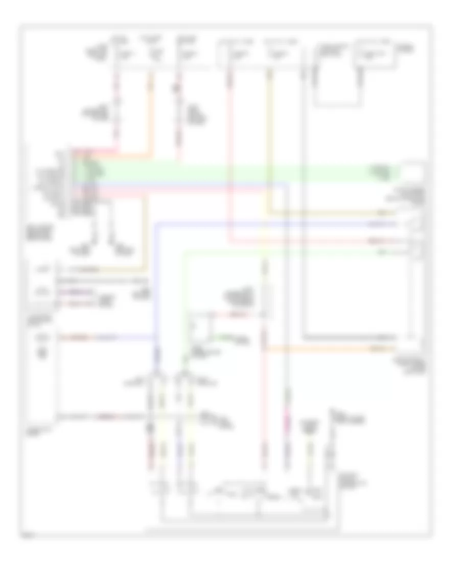
Headlamps Wiring Diagram, without DRL for Infiniti Q45 1997
List of elements for Headlamps Wiring Diagram, without DRL for Infiniti Q45 1997:
- 18b
- A/d gnd
- Acc
- Anti- theft system
- Auto
- Auto sens 5v
- Auto sens grd
- Auto sens sig
- Batt
- Body control module (bcm) (behind left side of dash)
- Combination meter
- Combo sw (auto)
- Diode (upper center of dash)
- Exterior lights system
- Fuse 14 7.5a
- Fuse 32 7.5a
- Fuse 53 15a
- Fuse 54 15a
- Fuse 7.5a
- Fuse block (j/b) (left kick panel)
- Fuse link a 120a
- Fuse, fusible link and relay box
- Fusible link box
- G100 (front of left front fender)
- G201 (right end of dash)
- G202 (left end of dash)
- Gnd
- Hdlp relay
- Head
- Headlamp relay (fuse, fusible link and relay box)
- High beam ind
- Horns system
- Hot at all times
- Hot in accy or on
- Hot in on or start
- Ign
- Illumination time control switch
- Interior lights system
- Joint conn- ector 3 (left end of dash)
- Joint connector 10 (top center of dash, behind air vents)
- Joint connector 4 (top left end of dash)
- Left headlamp
- Lighting switch (combination switch)
- Low
- Nca
- Off
- Optical sensor (top of dash, behind combination meter)
- Park
- Pass
- Pnk
- Right headlamp
- T/coord vr

 Čeština
 Dansk
Dansk Deutsch
 Ελληνικά
 English
 English
 Español
 Suomi
Suomi Français
 Français
 Hrvatski
 Magyar
 Italiano
 日本語
日本語 한국어
한국어 Nederlands
 Polski
 Português
 Português
 Română
 Русский
 Slovenčina
 Slovenščina
 Svenska
 Türkçe
 中文 (中国)