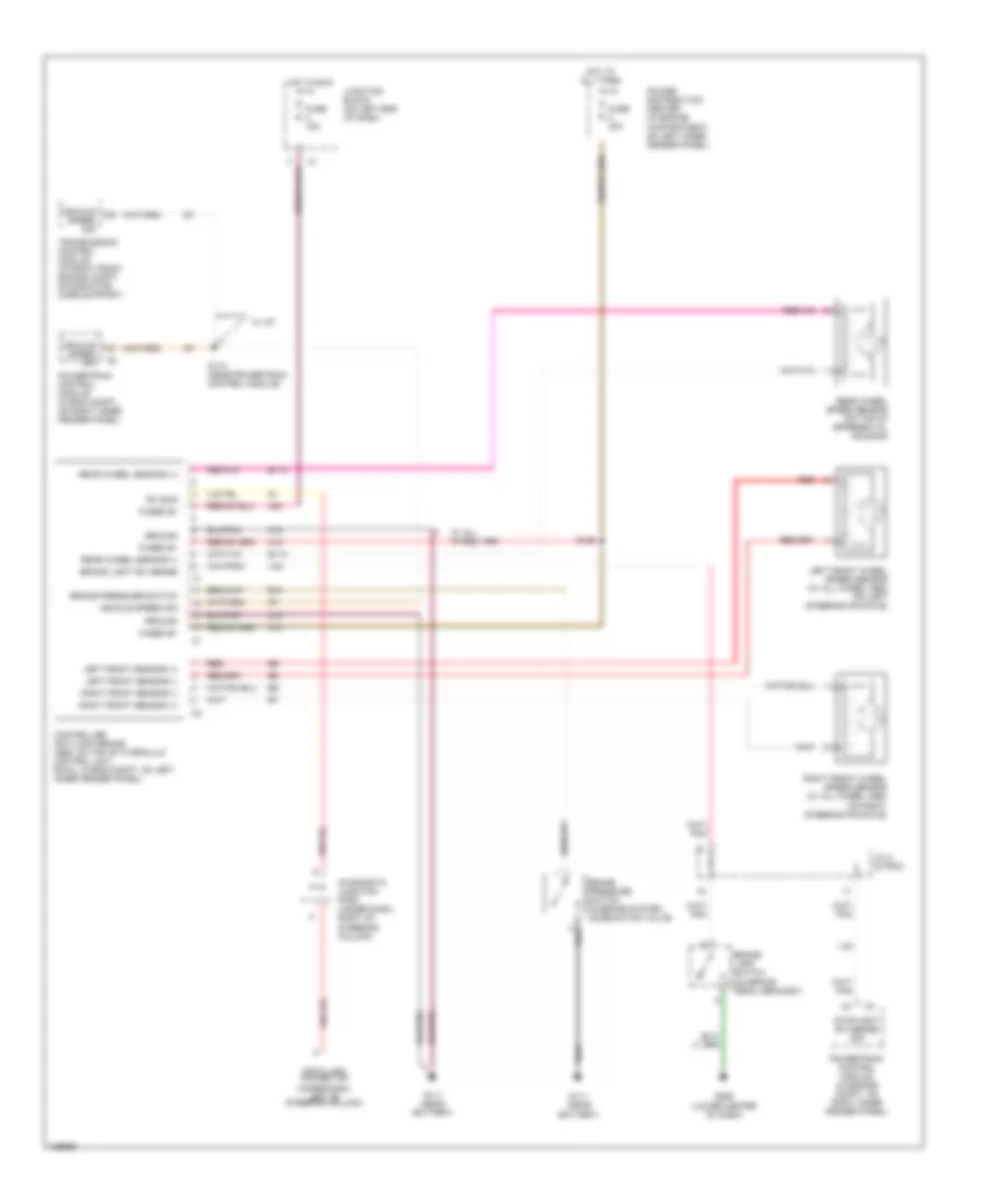
ANTI-LOCK BRAKES
Anti-lock Brake Wiring Diagrams for Dodge Dakota 2001
 https://portal-diagnostov.com/license.html
Automotive Electricians Portal FZCO
Automotive Electricians Portal FZCO
https://portal-diagnostov.com/license.html
https://portal-diagnostov.com/license.html
Automotive Electricians Portal FZCO
Automotive Electricians Portal FZCO
List of elements for Anti-lock Brake Wiring Diagrams for Dodge Dakota 2001:
- (under dash, left of steering column)
- A10
- A20
- B10
- B113
- B114
- Brake lamp switch (on brake pedal bracket)
- Brake light sw sense
- Brake pressure switch
- Brake pressure switch (in brake system combination valve)
- Controller anti-lock brake (abs: on top of hydraulic control unit, rwal: in eng compt, on left inner fender panel)
- Data link connector
- Diagnostic junction port (under dash, right of steering column)
- Fuse 15a
- Fuse 40a
- Fused b+
- G111 (near battery)
- G206 (lower center of dash)
- Ground
- Hot at all times
- Hot in run
- J/c 2 (in pdc)
- Junction block (on left end of dash)
- Left front sensor (+)
- Left front sensor (-)
- Left front wheel speed sensor (w/ all wheel abs) (on left steering knuckle)
- Pci bus
- Power distribution center (in engine compartment, on left inner fender panel)
- Powertrain control module (in eng compt, on right inner fender panel)
- Powertrain control module (in engine compt, on right inner fender panel)
- Rear wheel sensor (+)
- Rear wheel sensor (-)
- Rear wheel speed sensor (on top of differential housing)
- Red
- Right front sensor (+)
- Right front sensor (-)
- Right front wheel speed sensor (w/ all wheel abs) (on right steering knuckle)
- S126
- S174 (near powertrain control module)
- Stoplight sw sense sig
- Transmission control module (in right front engine compt, on radiator core support)
- V40
- Vehicle speed sig
- W/ a/t
- W/ all wheel abs
- Z19
 Čeština
 Dansk
Dansk Deutsch
 Ελληνικά
 English
 English
 Español
 Suomi
Suomi Français
 Français
 Hrvatski
 Magyar
 Italiano
 日本語
日本語 한국어
한국어 Nederlands
 Polski
 Português
 Português
 Română
 Русский
 Slovenčina
 Slovenščina
 Svenska
 Türkçe
 中文 (中国)
 עברית
עברית
