AIR CONDITIONING
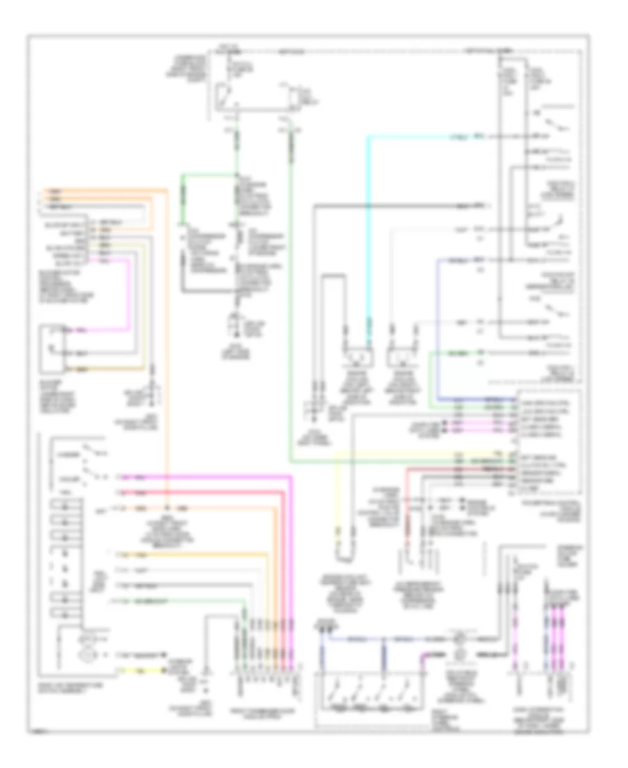
Automatic A/C Wiring Diagram (1 of 2) for Buick LeSabre Limited 2004
 https://portal-diagnostov.com/license.html
Automotive Electricians Portal FZCO
Automotive Electricians Portal FZCO
https://portal-diagnostov.com/license.html
https://portal-diagnostov.com/license.html
Automotive Electricians Portal FZCO
Automotive Electricians Portal FZCO
List of elements for Automatic A/C Wiring Diagram (1 of 2) for Buick LeSabre Limited 2004:
- (i/p harn, 13 cm from sunload sensor assembly breakout)
- (i/p harn, 6.5 cm from sunload sensor assembly breakout)
- (in hvac harn, 23.5 cm from c204 breakout)
- (in hvac harn, 30 cm from c204 breakout) s221
- (in hvac harn, 36.5 cm from c204 breakout)
- 5v ref
- A10
- A11
- A12
- Air temperature actuator (left) (left side of hvac housing)
- Air temperature actuator (right) (behind glove box, on right side of hvac assembly)
- Air temperature sensor (inside) (on dash, right of steering column)
- Air temperature sensor (lower left) (behind left dash air discharge vent)
- Air temperature sensor (lower right) (behind right dash air discharge vent)
- Air temperature sensor (upper left) (behind left dash air discharge vent)
- Air temperature sensor (upper right) (behind right dash air discharge vent)
- Amb air temp sig
- Amb light sens
- Ambient air temperature sensor
- Backlight lamps ctrl
- Battery
- Blwr sp ctrl
- C1 a1
- C11
- C12
- C13
- C3 a7
- C3 d12
- Class 2 serial
- Clock sig
- Computer data lines system
- D11
- D16
- Driver solar sig
- G100 (left side of engine)
- G201 (on right front door pillar)
- Grd
- Ground
- Headlights system
- Hot at all times
- Hot in on
- Hvac (batt) fuse 37 10a
- Hvac blo fuse 2 30a
- Hvac control module
- Hvac fuse 33 10a
- Ign 3 fuse 34 10a
- Ign 3 volt
- Ign 3 voltage
- In air temp sig
- Instrument panel integration module (behind left side of dash)
- Interior lights system
- Lft air door sig
- Lft temp dr ctrl
- Low ref
- Lower lft temp sig
- Lower rt temp sig
- Mod sig
- Mode actuator (on left side of hvac assembly)
- Mode door ctrl
- Mode dr pos sens
- Pass mdl fuse 25 10a
- Pass solar sig
- Rear fuse block (under left rear seat)
- Recirc door ctrl
- Recirc door sig
- Recirculation actuator (under right side of dash, to right of blower motor)
- Rt air door sig
- Rt temp dr ctrl
- S204
- S205 (i/p harn, 13.5 cm from hvac breakout)
- S208
- S222
- Solid state
- Splice pack sp100
- Splice pack sp201
- Sunload sensor assembly (on top center of dash)
- Tan
- Upper lh temp sig
- Upper rt temp sig
Automatic A/C Wiring Diagram (2 of 2) for Buick LeSabre Limited 2004
 https://portal-diagnostov.com/license.html
Automotive Electricians Portal FZCO
Automotive Electricians Portal FZCO
https://portal-diagnostov.com/license.html
https://portal-diagnostov.com/license.html
Automotive Electricians Portal FZCO
Automotive Electricians Portal FZCOList of elements for Automatic A/C Wiring Diagram (2 of 2) for Buick LeSabre Limited 2004:
- (in engine harn, 6.5 cm from idle air control valve connector breakout)
- 5v ref
- A/c clu fuse 26 15a
- A/c clu relay
- A/c compressor clutch (lower front of engine)
- A/c compressor clutch diode (on wiring harn, near a/c compressor)
- A/c refrigerant pressure sensor (behind a/c compressor, on a/c line)
- A10
- A11
- A12
- B10
- B11
- Bat
- Battery
- Blower motor (under right side of dash, above sound insulator)
- Blower motor control processor (behind dash, at right front side of blower motor)
- Blwr mtr grd
- Blwr sp input
- Blwr volt
- Breakout)
- C10
- C11
- Class 2 serial
- Clutch rly ctrl
- Cntl sig
- Computer data lines system
- Cool fan 1 fuse 30a
- Cool fan 2 fuse 46 30a
- Cooler
- Coolfan 1 relay 40 (low speed)
- Coolfan 2 relay 37 (high speed)
- Coolfan s/p relay 39 (series/parallel)
- D10
- Dash integration module (behind right side of dash, under sound insulator)
- E10
- E11
- Ect sens grd
- Ect sens sig
- Engine controls system
- Engine coolant temperature (ect) sensor (on rear of engine, near thermostat housing)
- Engine cooling fan (left) (behind left side of radiator)
- Engine cooling fan (right) (behind right side of radiator)
- F11
- Front passenger door module (fpdm)
- G10
- G100 (left side of engine)
- G103 (on inner body panel)
- G11
- G201 (on right front door pillar)
- Grd
- Ground
- High spd fan ctrl
- Hot at all times
- Hot in on
- Inflatable restraint steering wheel module coil (steering wheel)
- Interior lights system
- Low spd fan ctrl
- Nca
- Nca e
- Nca g
- Pdm low side input
- Pnk
- Powertrain control module (in air cleaner housing)
- Right air temperature switch assembly
- Right steering wheel controls
- S106
- S602 (in right front door harn, 10 cm from door module connector breakout)
- Sensor grd
- Sensor signal
- Sound systems
- Speed cntl
- Splice pack sp100
- Splice pack sp103
- Splice pack sp201
- Steering column fuse holder
- Sw grd
- Switch fuse 2a
- T10
- T11
- Tan
- Temp dn
- Temp up
- Underhood fuse block (right front side of engine compt)
- V10
- V11
- Vol dn
- Vol up
- Warmer
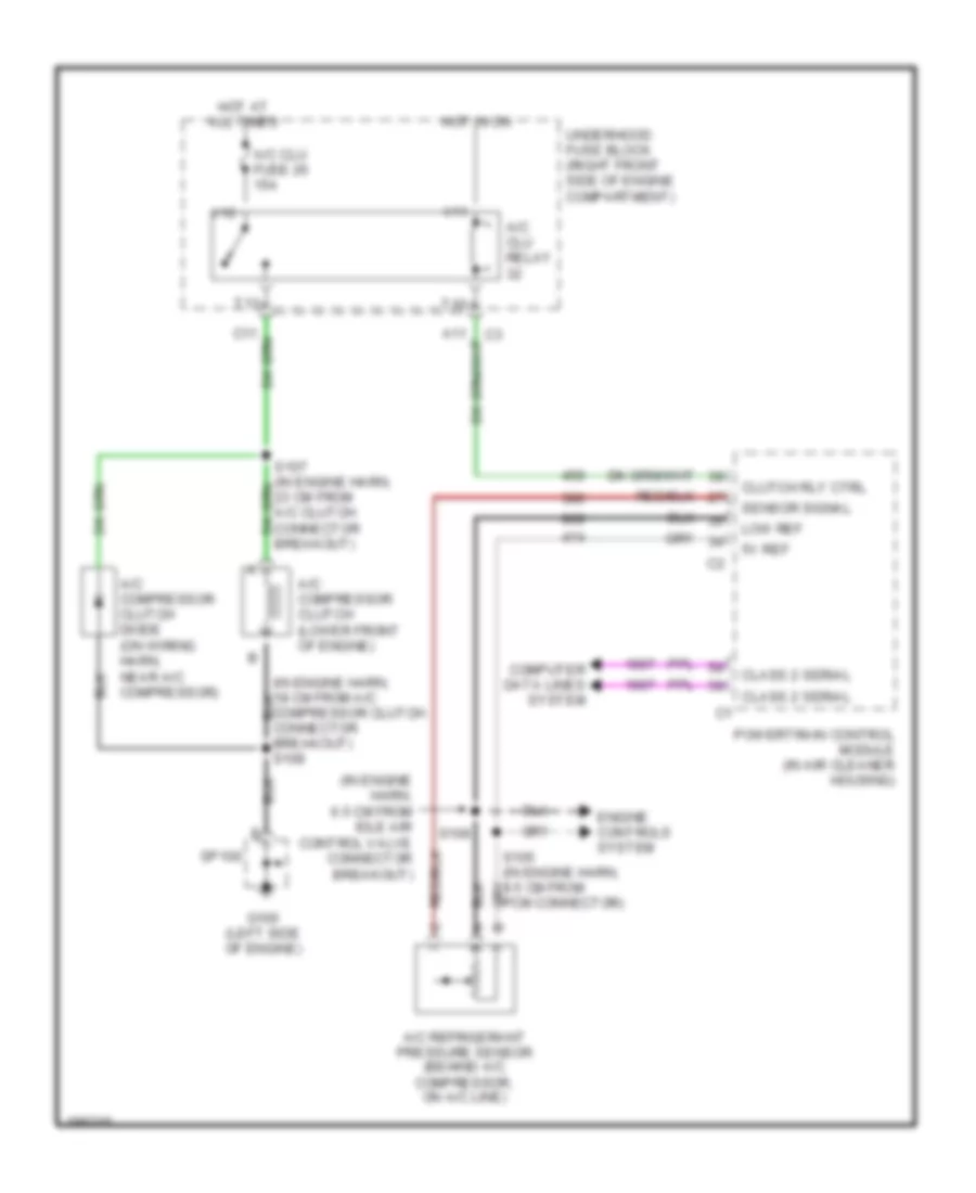
Compressor Wiring Diagram for Buick LeSabre Limited 2004
 https://portal-diagnostov.com/license.html
Automotive Electricians Portal FZCO
Automotive Electricians Portal FZCO
https://portal-diagnostov.com/license.html
https://portal-diagnostov.com/license.html
Automotive Electricians Portal FZCO
Automotive Electricians Portal FZCOList of elements for Compressor Wiring Diagram for Buick LeSabre Limited 2004:
- (in engine harn, 18 cm from a/c compressor clutch connector breakout) s108
- (in engine harn, 6.5 cm from idle air control valve connector breakout)
- 5v ref
- A/c clu fuse 26 15a
- A/c clu relay
- A/c compressor clutch (lower front of engine)
- A/c compressor clutch diode (on wiring harn, near a/c compressor)
- A/c refrigerant pressure sensor (behind a/c compressor, on a/c line)
- Class 2 serial
- Clutch rly ctrl
- Computer data lines system
- Engine controls system
- G100 (left side of engine)
- Hot at all times
- Hot in on
- Low ref
- Powertrain control module (in air cleaner housing)
- S106
- Sensor signal
- Sp100
- T10
- T11
- Underhood fuse block (right front side of engine compartment)
- V10
- V11
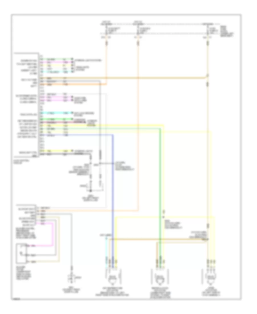
Manual A/C Wiring Diagram (1 of 2) for Buick LeSabre Limited 2004
 https://portal-diagnostov.com/license.html
Automotive Electricians Portal FZCO
Automotive Electricians Portal FZCO
https://portal-diagnostov.com/license.html
https://portal-diagnostov.com/license.html
Automotive Electricians Portal FZCO
Automotive Electricians Portal FZCOList of elements for Manual A/C Wiring Diagram (1 of 2) for Buick LeSabre Limited 2004:
- (i/p harn, 6.5 cm outside from radio breakout)
- (in hvac harn, 30 cm from c204 breakout) s221
- (not used)
- 5v ref
- A10
- A11
- A12
- A13
- A14
- A15
- A16
- Air temp dr ctrl
- Air temperature actuator (behind dash, at left front side of blower motor)
- Ambient light
- Anti-lock brakes system
- B10
- B11
- B12
- B13
- B14
- B15
- B16
- Backlight ctrl
- Batt
- Battery
- Blower control processor (behind dash, at right front side of blower motor)
- Blower motor (under right side of dash, above sound insulator)
- Blwr mtr grd
- Blwr sp input
- Blwr speed cntrl
- Blwr volt
- C1 a10
- Class 2 serial
- Computer data lines system
- D12
- Dimmer sw sig
- G200 (on left front door pillar)
- G201 (on right front door pillar)
- Grd
- Headlights system
- Hot at all times
- Hot in on
- Hvac batt fuse 37 10a
- Hvac blo fuse 2 30a
- Hvac control module
- Hvac fuse 33 10a
- Ign 3 voltage
- Int lamp sw sig
- Interior lights system
- Key reminder sw
- Low ref
- Mode actuator (on left side of hvac assembly)
- Motor low ref
- Rear fuse block (under left rear seat)
- Recirc dr mtr
- Recirculation actuator (under right side of dash, to right of blower motor)
- S208 (i/p harn, 13 cm from sunload sensor assembly breakout)
- S222 (in hvac harn, 23.5 cm from c204 breakout)
- S253
- Solid state
- Sp200
- Sp201
- Speed cntl
- Trac cntrl sw
- Twilight sentinel
- Warnings system
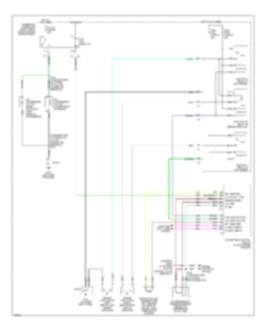
Manual A/C Wiring Diagram (2 of 2) for Buick LeSabre Limited 2004
 https://portal-diagnostov.com/license.html
Automotive Electricians Portal FZCO
Automotive Electricians Portal FZCO
https://portal-diagnostov.com/license.html
https://portal-diagnostov.com/license.html
Automotive Electricians Portal FZCO
Automotive Electricians Portal FZCOList of elements for Manual A/C Wiring Diagram (2 of 2) for Buick LeSabre Limited 2004:
- (in engine harn, 18 cm from a/c clutch connector breakout) s108
- (in engine harn, 6.5 cm from idle air control valve breakout)
- 5v ref
- A/c clu fuse 26 15a
- A/c clu relay 32
- A/c compressor clutch (lower front of engine)
- A/c compressor clutch diode (on wiring harn, near a/c compressor)
- A/c refrigerant pressure sensor (behind a/c compressor, on a/c line)
- A10
- A11
- B10
- B11
- C10
- C11
- Class 2 serial
- Clutch rly ctrl
- Computer data lines system
- Cool fan 1 fuse 47 30a
- Cool fan 2 fuse 46 30a
- Coolfan 1 relay 40 (low speed)
- Coolfan 2 relay 37 (high speed)
- Coolfan s/p relay 39 (series/parallel)
- D10
- E10
- E11
- Ect sens grd
- Ect sens sig
- Engine controls system
- Engine coolant temperature (ect) sensor (on rear of
- Engine cooling fan (left) (behind left side of radiator)
- Engine cooling fan (right) (behind right side of radiator)
- Engine, near thermostat housing)
- F11
- G10
- G100 (left side of engine)
- G103 (on inner body panel)
- G11
- High spd fan ctrl
- Hot at all times
- Hot in on
- Low ref
- Low spd fan ctrl
- Powertrain control module (in air cleaner housing)
- S106
- Sensor signal
- Sp100
- Sp103
- T10
- T11
- Underhood fuse block (right front side of engine compartment)
- V10
- V11

 Čeština
 Dansk
Dansk Deutsch
 Ελληνικά
 English
 English
 Español
 Suomi
Suomi Français
 Français
 Hrvatski
 Magyar
 Italiano
 日本語
日本語 한국어
한국어 Nederlands
 Polski
 Português
 Português
 Română
 Русский
 Slovenčina
 Slovenščina
 Svenska
 Türkçe
 中文 (中国)
