ANTI-LOCK BRAKES
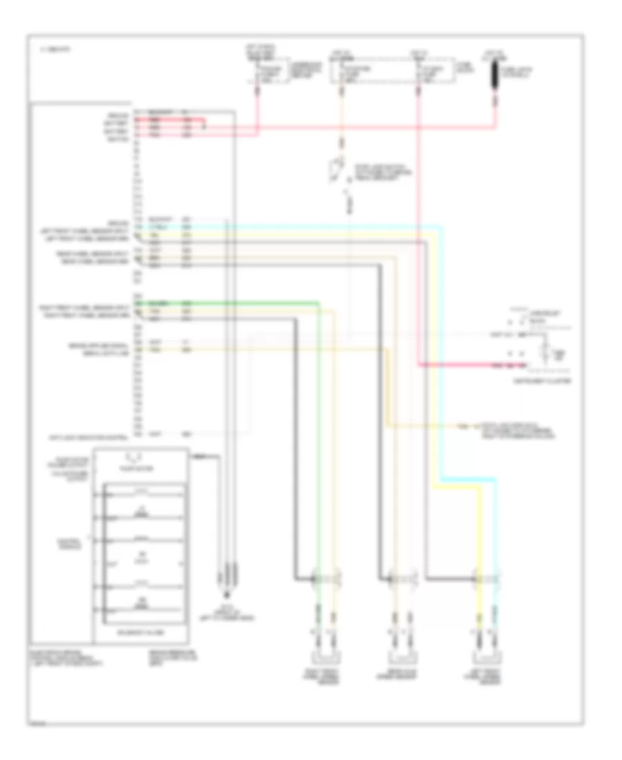
Anti-lock Brake Wiring Diagrams for Buick Roadmaster Estate Wagon 1995
 https://portal-diagnostov.com/license.html
Automotive Electricians Portal FZCO
Automotive Electricians Portal FZCO
https://portal-diagnostov.com/license.html
https://portal-diagnostov.com/license.html
Automotive Electricians Portal FZCO
Automotive Electricians Portal FZCO
List of elements for Anti-lock Brake Wiring Diagrams for Buick Roadmaster Estate Wagon 1995:
- A11
- Abs ind
- Anti-lock indicator control
- Battery
- Brake pressure modulator valve (bpm)
- Buick
- C 1995 vftc
- Chevrolet
- Control signals
- Data link conn (dlc) m (attached to i/p carrier, right of steering column)
- Electronic brake control module (ebcm) ( left front of eng compt)
- Fuse block
- G110 (front of left cylinder head)
- Ground
- Hot at all times
- Hot in run
- Hot in run, bulb test or start
- I/p indic fuse 10a
- Ignition
- Instrument cluster
- Left front wheel sensor grd
- Left front wheel sensor input
- Left front wheel speed sensor
- Nca
- Out
- Pcm/ign fuse 5 10a
- Pnk
- Pump motor
- Pump motor power output
- Rear axle speed sensor
- Rear wheel sensor grd
- Rear wheel sensor input
- Red
- Right front wheel sensor grd
- Right front wheel sensor input
- Right front wheel speed sensor
- Serial data line
- Solenoid valves
- Stop lamp switch (attached to brake pedal bracket)
- Stop/hzd fuse 20a
- Tan
- Underhood electrical center
- Valve power output
 Čeština
 Dansk
Dansk Deutsch
 Ελληνικά
 English
 English
 Español
 Suomi
Suomi Français
 Français
 Hrvatski
 Magyar
 Italiano
 日本語
日本語 한국어
한국어 Nederlands
 Polski
 Português
 Português
 Română
 Русский
 Slovenčina
 Slovenščina
 Svenska
 Türkçe
 中文 (中国)
 עברית
עברית
