
 Čeština
 Dansk
Dansk Deutsch
 Ελληνικά
 English
 English
 Español
 Suomi
Suomi Français
 Français
 Hrvatski
 Magyar
 Italiano
 日本語
日本語 한국어
한국어 Nederlands
 Polski
 Português
 Português
 Română
 Русский
 Slovenčina
 Slovenščina
 Svenska
 Türkçe
 中文 (中国)

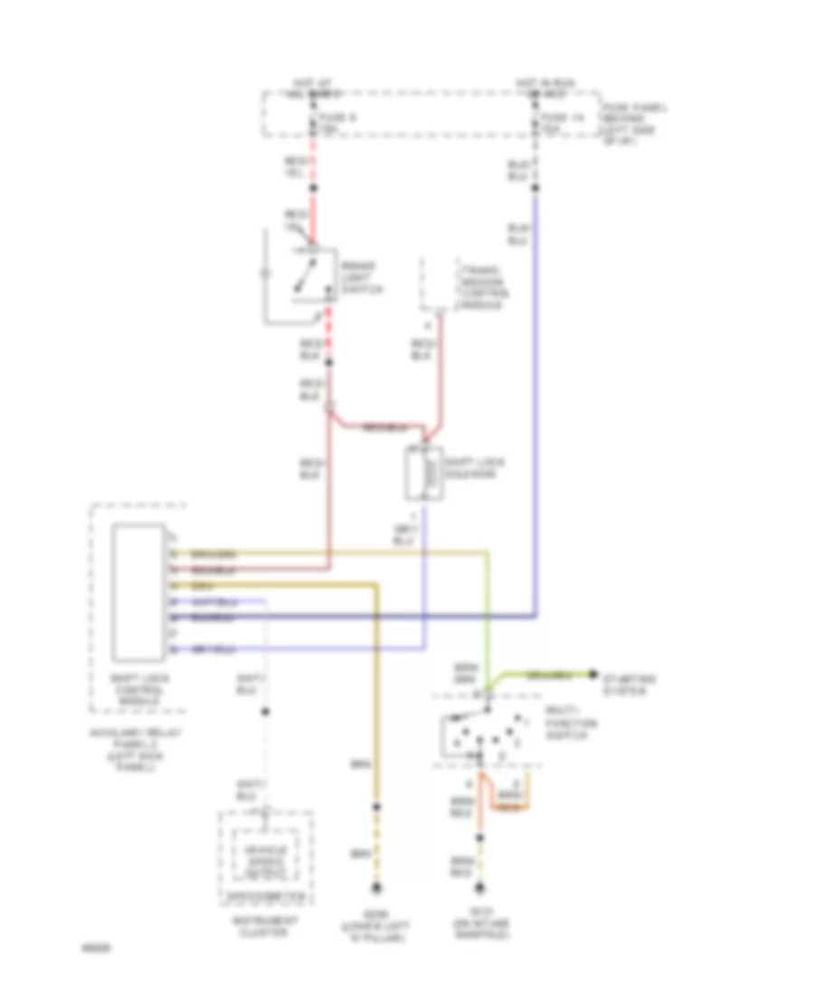
SHIFT INTERLOCK
Shift Interlock Wiring Diagram for Audi 100 CS 1994
List of elements for Shift Interlock Wiring Diagram for Audi 100 CS 1994:

AIR CONDITIONINGANTI-THEFTCOMPUTER DATA LINESANTI-LOCK BRAKESDEFOGGERSCRUISE CONTROLELECTRONIC POWER STEERINGHORNEXTERIOR LIGHTSCOOLING FANINTERIOR LIGHTSGROUND DISTRIBUTIONHEADLIGHTSENGINE PERFORMANCEINSTRUMENT CLUSTERPOWER DOOR LOCKSPOWER DISTRIBUTIONMEMORY SYSTEMSPOWER SEATSPOWER TOP/SUNROOFPOWER MIRRORSPOWER WINDOWSRADIOSHIFT INTERLOCKSTARTING/CHARGINGSUPPLEMENTAL RESTRAINTSTRANSMISSIONTRUNK, TAILGATE, FUEL DOORWARNING SYSTEMSWIPER/WASHER