INSTRUMENT CLUSTER
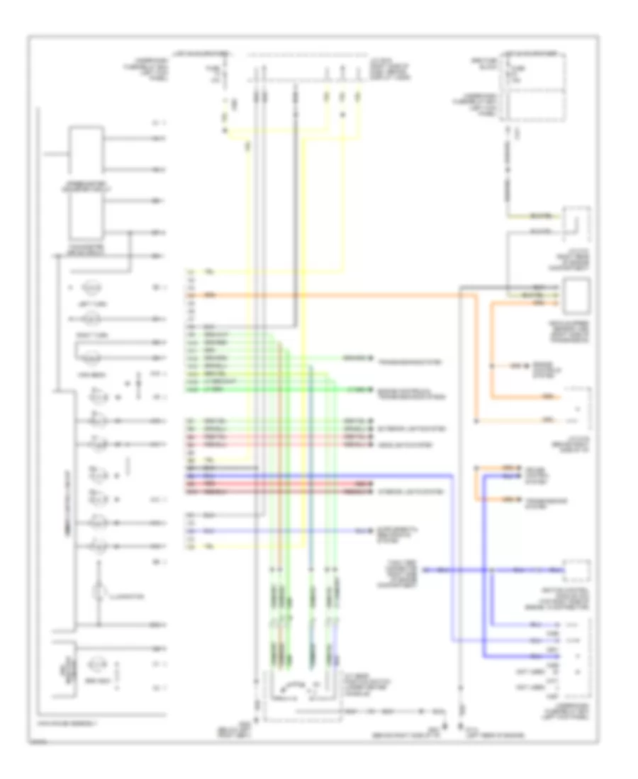
Main Gauge Assembly Wiring Diagram, with Electro-Luminescent Gauges (1 of 2) for Honda Prelude S 1996
 https://portal-diagnostov.com/license.html
Automotive Electricians Portal FZCO
Automotive Electricians Portal FZCO
https://portal-diagnostov.com/license.html
https://portal-diagnostov.com/license.html
Automotive Electricians Portal FZCO
Automotive Electricians Portal FZCO
List of elements for Main Gauge Assembly Wiring Diagram, with Electro-Luminescent Gauges (1 of 2) for Honda Prelude S 1996:
- (not used)
- 10a
- Battery
- C422
- C601
- Dc/ac inverter (left side of main gauge assembly)
- Dimmer control circuit
- Dimming circuit
- Dimming input
- Dimming output
- Engine controls system, transmissions system
- Exterior lights system
- Fuse
- Fuse 43 clock/radio
- G201 (left side of i/p)
- G302 (below center console)
- Ground
- H10
- Headlights system
- High beam
- Hot at all times
- Hot in on or start
- Ignition
- Illumination
- Interior lights system
- Inverter
- J/c c419 (behind right i/p)
- J/c c619 (right side of dash, behind display visor)
- Left turn
- Main gauge assembly
- Pnk
- R10
- R11
- R12
- R13
- R14
- Red
- Right turn
- Speed sig
- Speedo heater
- Speedo thermistor
- Speedometer crt
- Speedometer/odometer/ tachometer circuit
- Spped sig
- Srs indic
- Srs indicator circuit
- Sub guage assembly
- T10
- Tach heater
- Tachometer crt
- Transmissions system
- Under-dash fuse/relay box (left kick panel)
- Under-hood fuse/relay box (right rear of engine compartment)
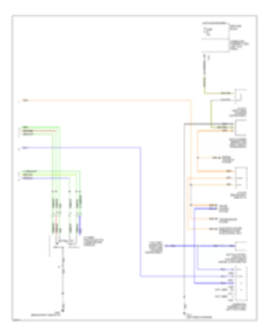
Main Gauge Assembly Wiring Diagram, with Electro-Luminescent Gauges (2 of 2) for Honda Prelude S 1996
 https://portal-diagnostov.com/license.html
Automotive Electricians Portal FZCO
Automotive Electricians Portal FZCO
https://portal-diagnostov.com/license.html
https://portal-diagnostov.com/license.html
Automotive Electricians Portal FZCO
Automotive Electricians Portal FZCOList of elements for Main Gauge Assembly Wiring Diagram, with Electro-Luminescent Gauges (2 of 2) for Honda Prelude S 1996:
- (not used)
- 15a
- A/t gear position switch (under center console)
- C467
- C469
- C471
- C601
- Cruise control system
- Electronic power steering system (4ws control unit)
- Engine controls system
- Fuse
- G114 (left rear of engine)
- G201 (behind right side of i/p)
- Hot in on or start
- Ignition control module (icm) (top right side of engine, in distributor)
- J/c c131 (right rear of engine compartment)
- J/c c419 (behind right side of i/p)
- Srs fuse block
- Tach test connector (right side of engine compartment)
- Transmissions system
- Under-dash fuse/relay box (left kick panel)
- Vehicle speed sensor (vss) (right side of transmission)
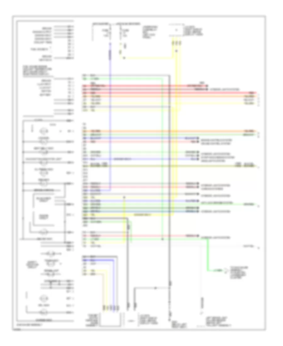
Main Gauge Assembly Wiring Diagram, without Electro-Luminescent Gauges for Honda Prelude S 1996
 https://portal-diagnostov.com/license.html
Automotive Electricians Portal FZCO
Automotive Electricians Portal FZCO
https://portal-diagnostov.com/license.html
https://portal-diagnostov.com/license.html
Automotive Electricians Portal FZCO
Automotive Electricians Portal FZCOList of elements for Main Gauge Assembly Wiring Diagram, without Electro-Luminescent Gauges for Honda Prelude S 1996:
- (not used)
- 10a
- 15a
- A/t gear position switch (under center console)
- A10
- A11
- A12
- A13
- A14
- A15
- A16
- B10
- C467
- C469
- C471
- C601
- Cruise control system
- Dimmer control circuit
- Engine controls & transmissions systems
- Engine controls system
- Exterior lights system
- Fuse
- G114 (left rear of engine)
- G201 (behind right side of i/p)
- G300 (below left front seat)
- Headlights system
- High beam
- Hot in on or start
- Ignition control module (icm) (top right side of engine, in distributor)
- Illumination
- Interior lights system
- J/c c131 (right rear of engine compartment)
- J/c c419 (behind right side of i/p)
- J/c c619 (right side of dash, behind display visor)
- Left turn
- Main gauge assembly
- Red
- Right turn
- Speedometer/ odometer circuit
- Srs fuse block
- Srs indic
- Srs indicator circuit
- Tach test connector (right side of engine compartment)
- Tachometer drive circuit
- Transmissions system
- Under-dash fuse/relay box (left kick panel)
- Vehicle speed sensor (vss) (right side of transmission)
Sub Gauge Assembly Wiring Diagram (1 of 2) for Honda Prelude S 1996
 https://portal-diagnostov.com/license.html
Automotive Electricians Portal FZCO
Automotive Electricians Portal FZCO
https://portal-diagnostov.com/license.html
https://portal-diagnostov.com/license.html
Automotive Electricians Portal FZCO
Automotive Electricians Portal FZCOList of elements for Sub Gauge Assembly Wiring Diagram (1 of 2) for Honda Prelude S 1996:
- (1995) (1996)
- (canada only)
- 10a
- 7.5a
- Abs indic
- Anti-lock brakes system
- Battery
- Brake lamp
- Brake warning
- Bulb check circuit
- C601
- Charge indic
- Clock
- Coolant temp
- Cruise control system
- Cruise indic
- D10
- Dimming circuit
- Dimming input
- Dimming output
- Door indic
- Drl indic
- E10
- E11
- E12
- E13
- E14
- E15
- E16
- E17
- E18
- E19
- E20
- E21
- E22
- E23
- E24
- E25
- E26
- E27
- E28
- E29
- E30
- Engine controls system
- Fuel gauge in
- Fuel gauge/ engine coolant temperature (ect) gauge circuit (electronic display)
- Fuse
- G300 (below left front seat)
- Ground
- Headlights system
- Hot in on or start
- Hot in start
- Ignition
- Ignition in
- Illum input
- Illum out
- Interior lights system
- J/c c619 (right side of dash, behind display visor)
- Left brake light failure sensor (behind left taillight assembly)
- Low fuel
- Malfunction indicator light
- Oil press indic
- Red
- Safety indicator circuit
- Seat belt indic
- Starting/charging system
- Sub gauge assembly
- Time set switch (near sub- gauge assembly)
- To main gauge assembly (w/ electro- luminescent cluster)
- Trunk indic
- Under-dash fuse/relay box (left kick panel)
- Warning systems
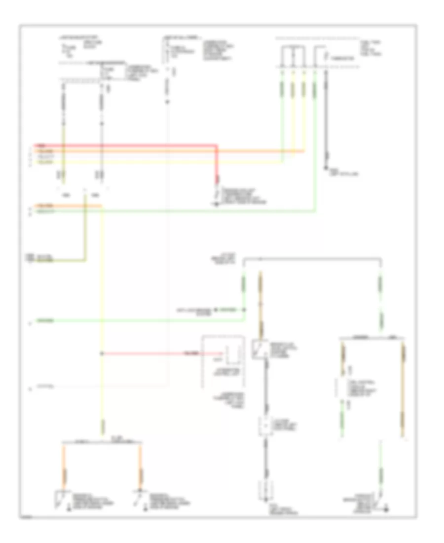
Sub Gauge Assembly Wiring Diagram (2 of 2) for Honda Prelude S 1996
 https://portal-diagnostov.com/license.html
Automotive Electricians Portal FZCO
Automotive Electricians Portal FZCO
https://portal-diagnostov.com/license.html
https://portal-diagnostov.com/license.html
Automotive Electricians Portal FZCO
Automotive Electricians Portal FZCOList of elements for Sub Gauge Assembly Wiring Diagram (2 of 2) for Honda Prelude S 1996:
- (1995) (1996)
- 10a
- 15a
- 7.5a
- Anti-lock brakes system
- Brake fluid level switch (master cylinder)
- C418
- C422
- C473
- C601
- Canada
- Drl control module (behind right side of i/p)
- Engine coolant temperature (ect) sending unit (right side of engine)
- Engine oil pressure switch (center rear under- side of engine)
- Fuel tank unit (top of fuel tank)
- Fuse
- Fuse 43 clock/radio
- G101 (left front fender apron)
- G308 (left 'b' pillar)
- Hot at all times
- Hot in on or start
- Integrated control unit
- J/c c326 (above left kick panel)
- J/c c447 (behind left side of i/p)
- Parking brake switch (below center console)
- Red
- S only
- Srs fuse block
- Si, sr, vtec & sr-v
- Thermistor
- Under-dash fuse/relay box (left kick panel)
- Under-hood fuse/relay box (right rear of engine compartment)
- Usa

 Čeština
 Dansk
Dansk Deutsch
 Ελληνικά
 English
 English
 Español
 Suomi
Suomi Français
 Français
 Hrvatski
 Magyar
 Italiano
 日本語
日本語 한국어
한국어 Nederlands
 Polski
 Português
 Português
 Română
 Русский
 Slovenčina
 Slovenščina
 Svenska
 Türkçe
 中文 (中国)
