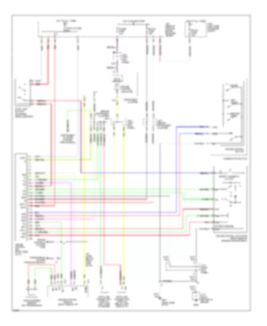
CRUISE CONTROL
Cruise Control Wiring Diagram for Lexus LS 400 1997
List of elements for Cruise Control Wiring Diagram for Lexus LS 400 1997:
- (behind instrument cluster) j/b 3
- (i/p harn, below right side of i/p)
- (instrument cluster system- drive signal)
- A/d
- A11
- A19
- B22
- Batt
- C11
- C16
- C22
- Cancel
- Ccs
- Cms
- Combination switch
- Cruise control actuator (right rear of engine compartment)
- Cruise control ecu (right side of i/p)
- Cruise control indicator
- Cruise control switch
- Data link connector 1 (partial) (left side of engine)
- Data link connector 2 (partial) (below left side of i/p)
- E/g
- E11
- E14
- E18
- Ect
- Ecu-b fuse 15a
- Ecu-ig fuse 15a
- Engine control module (right side of i/p)
- Engine controls system (tps)
- G201 (right side of i/p)
- G206
- Gauge fuse 10a
- Gnd
- Hot at all times
- Hot in on or start
- I13
- Idl
- Idl 1
- Instrument cluster
- J/b 1 (rear of parking brake release lever)
- J/b 2 (left side of engine compt)
- J/b 3 (behind instrument cluster)
- J/b 4 (left kick panel)
- J/c 2 (right center i/p brace)
- J/c 3 (right kick panel)
- J11
- K10
- K11
- L12
- Od1
- Pnk
- Potentiometer
- Red
- Resume/ accel
- Safety magnetic clutch
- Set/ coast
- Solid state
- Sp+
- Sp-
- Spd
- Spdm
- Stop light switch (on brake pedal support)
- Stop lp fuse 25a
- Stp+
- Stp-
- Transmission system (trans solenoid 2)
- Vehicle speed sensor (on transmission)
- Vr1
- Vr1/+
- Vr2
- Vr3
- Vr3/-
 Čeština
 Dansk
Dansk Deutsch
 Ελληνικά
 English
 English
 Español
 Suomi
Suomi Français
 Français
 Hrvatski
 Magyar
 Italiano
 日本語
日本語 한국어
한국어 Nederlands
 Polski
 Português
 Português
 Română
 Русский
 Slovenčina
 Slovenščina
 Svenska
 Türkçe
 中文 (中国)
 עברית
עברית