ANTI-THEFT
Anti-theft Wiring Diagram for Lexus LS 400 1997
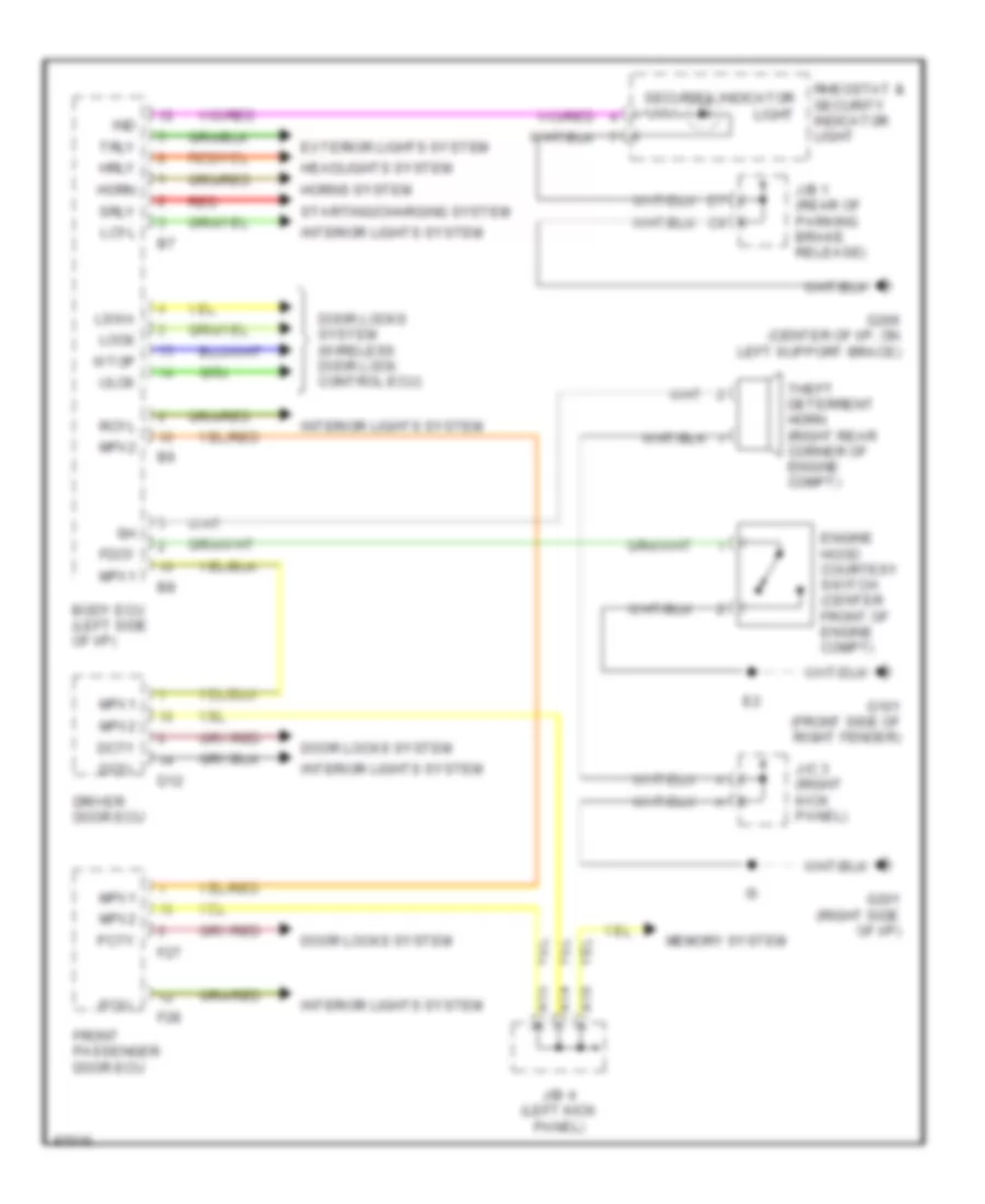
List of elements for Anti-theft Wiring Diagram for Lexus LS 400 1997:
- A14
- A15
- A16
- Body ecu (left side of i/p)
- D12
- Dcty
- Dcyl
- Door locks system
- Door locks system (wireless door lock control ecu)
- Driver door ecu
- Engine hood courtesy switch (center front of engine compt)
- Exterior lights system
- F27
- F28
- Fdcy
- Front passenger door ecu
- G101 (front side of right fender)
- G201 (right side of i/p)
- G206 (center of i/p, on left support brace)
- Headlights system
- Horn
- Horns system
- Hrly
- Ind
- Interior lights system
- J/b 1 (rear of parking brake release)
- J/b 4 (left kick panel)
- J/c 3 (right kick panel)
- Lcyl
- Lock
- Lswa
- Memory system
- Mpx1
- Mpx2
- Pcty
- Pcyl
- Rcyl
- Red
- Rheostat & security indicator light
- Security indicator light
- Srly
- Starting/charging system
- Theft deterrent horn (right rear corner of engine compt)
- Trly
- Ulck
- Wtop
 English