ANTI-THEFT
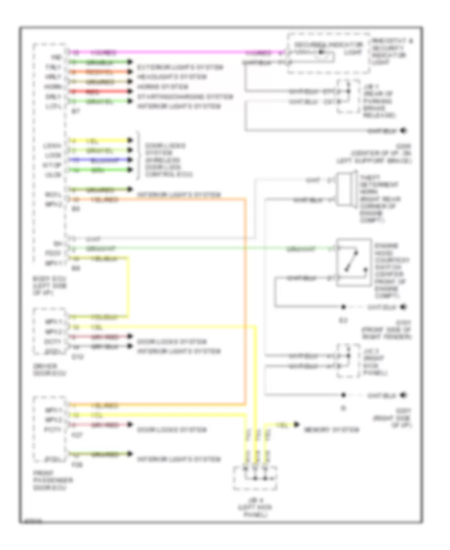
Anti-theft Wiring Diagram for Lexus LS 400 1997
List of elements for Anti-theft Wiring Diagram for Lexus LS 400 1997:
- A14
- A15
- A16
- Body ecu (left side of i/p)
- D12
- Dcty
- Dcyl
- Door locks system
- Door locks system (wireless door lock control ecu)
- Driver door ecu
- Engine hood courtesy switch (center front of engine compt)
- Exterior lights system
- F27
- F28
- Fdcy
- Front passenger door ecu
- G101 (front side of right fender)
- G201 (right side of i/p)
- G206 (center of i/p, on left support brace)
- Headlights system
- Horn
- Horns system
- Hrly
- Ind
- Interior lights system
- J/b 1 (rear of parking brake release)
- J/b 4 (left kick panel)
- J/c 3 (right kick panel)
- Lcyl
- Lock
- Lswa
- Memory system
- Mpx1
- Mpx2
- Pcty
- Pcyl
- Rcyl
- Red
- Rheostat & security indicator light
- Security indicator light
- Srly
- Starting/charging system
- Theft deterrent horn (right rear corner of engine compt)
- Trly
- Ulck
- Wtop
 Čeština
 Dansk
Dansk Deutsch
 Ελληνικά
 English
 English
 Español
 Suomi
Suomi Français
 Français
 עברית
עברית Hrvatski
 Magyar
 Italiano
 日本語
日本語 한국어
한국어 Nederlands
 Polski
 Português
 Português
 Română
 Русский
 Slovenčina
 Slovenščina
 Svenska
 Türkçe
 中文 (中国)