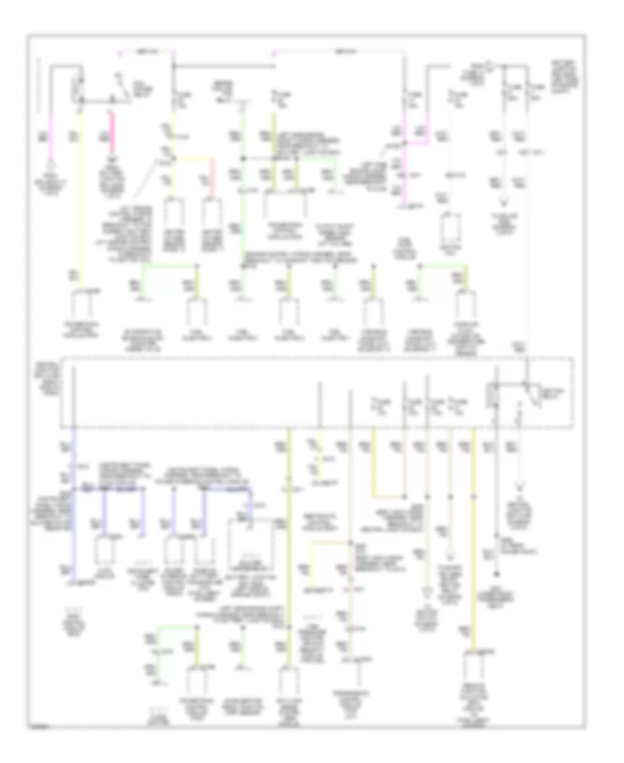
POWER DISTRIBUTION
Power Distribution Wiring Diagram (1 of 5) for Ford Fiesta Titanium 2013
 https://portal-diagnostov.com/license.html
Automotive Electricians Portal FZCO
Automotive Electricians Portal FZCO
https://portal-diagnostov.com/license.html
https://portal-diagnostov.com/license.html
Automotive Electricians Portal FZCO
Automotive Electricians Portal FZCO
List of elements for Power Distribution Wiring Diagram (1 of 5) for Ford Fiesta Titanium 2013:
- (engine control wiring harness, in breakout to transmission control module) s100
- (left side engine compt wiring harness, near breakout to battery junction box) s120
- (left side engine compt wiring harness, near breakout to powertrain control module) s114
- A/c clutch relay
- Anti-lock brake system (abs) module
- Battery
- Battery junction box (bjb) (left side of engine compt)
- Blower motor relay
- Body control module (pcm)
- C1100a
- C133
- C1617a
- C1617b
- C1617c
- C1750a
- C175b
- C210
- C211
- C2280a
- C2368a
- Daytime running lamps (drl) relay
- Engine cooling fan relay
- Fuse 10a
- Fuse 15a
- Fuse 20a
- Fuse 2a
- Fuse 30a
- Fuse 40a
- Fuse 50a
- Fuse 7.5a
- Generator
- High beam relay
- High current battery junction box (bjb) (at battery)
- Low beam relay
- Mega fuse 1 450a
- Mega fuse 2 60a
- Mega fuse 3 200a
- Natural vacuum leak detection module (nvldm)
- Power steering control module (pscm)
- Powertrain control module (pcm)
- Red
- Starter inhibit relay
- Starter motor
- To battery junction box (bjb) (diagram 2 of 5)
- To fuse 5 (diagram 2 of 5)
- Transmission control module (tcm) (a/t)
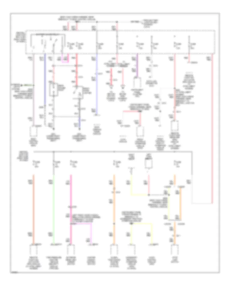
Power Distribution Wiring Diagram (2 of 5) for Ford Fiesta Titanium 2013
 https://portal-diagnostov.com/license.html
Automotive Electricians Portal FZCO
Automotive Electricians Portal FZCO
https://portal-diagnostov.com/license.html
https://portal-diagnostov.com/license.html
Automotive Electricians Portal FZCO
Automotive Electricians Portal FZCOList of elements for Power Distribution Wiring Diagram (2 of 5) for Ford Fiesta Titanium 2013:
- (engine control wiring harness, near breakout to camshaft position sensor) s102
- (instrument panel wiring harness, near breakout to power steering control module) s213
- (left side engine compt wiring harness, near breakout
- (left side engine compt wiring harness, near breakout to battery junction box) s122
- (m/t: engine control wiring harness, in breakout to high current battery junction box) (a/t: engine control wiring harness, in breakout to ignition coil)
- Accelerator pedal position (app) sensor
- Anti-lock brake system (abs) module
- Battery junction box (bjb) (left side of engine compt)
- Blower motor relay
- Body control module (bcm)
- C133
- C1750a
- C175b
- C210
- C211
- C212
- C2280b
- C228a
- C2368b
- C310a
- C3416
- C3503b
- C4321a
- Central junction box (cjb) (right side of dash)
- Engine cooling fan relay
- Evaporative emission (evap) canister purge valve
- Floor shifter
- From a fuse 10 (diagram 1 of 5)
- From battery junction box (bjb) (diagram 1 of 5)
- From splice s114 (diagram 1 of 5)
- Fuel injector 1
- Fuel injector 2
- Fuel injector 3
- Fuel injector 4
- Fuel pump control module
- Fuse 10a
- Fuse 15a
- Fuse 30a
- Fuse 60a
- Fuse 7.5a
- G301 (under front passenger's seat)
- Heated oxygen sensor (ho2s) 11
- Heated oxygen sensor (ho2s) 12
- Hvac module
- Ignition coil
- Ignition relay
- Instrument panel cluster (ipc)
- Mass air flow/ intake air temperature (maf/iat) sensor
- Output shaft speed (oss) sensor (m/t w/o abs)
- Passive anti-theft transceiver (w/o intelligent access)
- Pcm power relay
- Power steering control module (pscm)
- Powertrain control module (pcm)
- Remote function actuator (rfa) module (w/ intelligent access)
- Restraints control module (rcm)
- S103
- S126
- S228
- S239 (instrument panel wiring harness, near breakout to blower motor resistor)
- S256 (w/ rear power point)
- S257 (a/t) (body main wiring harness, near breakout to c214)
- S259 (body main wiring harness, near breakout to central junction box)
- Tire pressure monitor/ vehicle security module (tpm/vsm)
- To central junction box (cjb) (diagram 5 of 5)
- To g105)
- To ignition switch (diagram 4 of 5)
- To smart keyless entry ignition relay (diagram 4 of 5)
- To splice s252 (diagram 3 of 5)
- Transmission control module (tcm) (a/t)
- Variable camshaft timing (vct) solenoid 11
- Variable camshaft timing (vct) solenoid 12
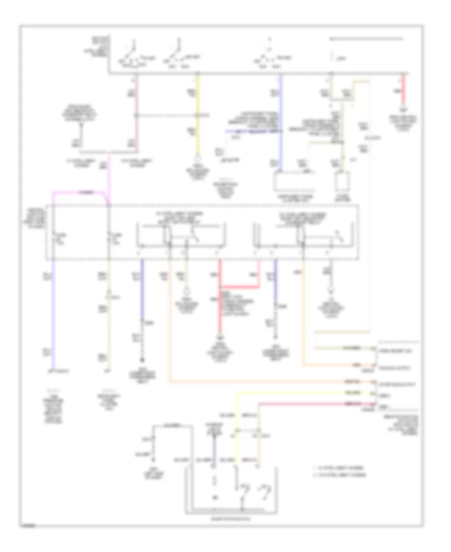
Power Distribution Wiring Diagram (3 of 5) for Ford Fiesta Titanium 2013
 https://portal-diagnostov.com/license.html
Automotive Electricians Portal FZCO
Automotive Electricians Portal FZCO
https://portal-diagnostov.com/license.html
https://portal-diagnostov.com/license.html
Automotive Electricians Portal FZCO
Automotive Electricians Portal FZCOList of elements for Power Distribution Wiring Diagram (3 of 5) for Ford Fiesta Titanium 2013:
- (body main wiring harness, near breakout to body control module) s252
- (body main wiring harness, near breakout to central junction box)
- (instrument panel wiring harness, in breakout to accessory protocol interface module) s201
- (instrument panel wiring harness, near breakout to g202) s225
- (left front door window regulator wiring harness, in breakout to c339) (w/ power windows) s504
- 4 door
- 5 door
- Accessory protocol interface module (apim) (w/ sync)
- Audio control module (acm)
- Battery saver relay
- Body control module (bcm)
- C211
- C212
- C213
- C2280c
- C228a
- C240a
- C314
- C315
- C339 a8
- C3503a
- C4321a
- C504a
- Central junction box (cjb) (right side of dash)
- Data link connector (dlc)
- Exterior rear view mirror switch
- From battery junction box f (diagram 2 of 5)
- Front cigar lighter
- Front control/ display interface module (fcdim)
- Front controls interface module (fcim)
- Fuse 10a
- Fuse 15a
- Fuse 20a
- Fuse 7.5a
- G301 (under front passenger's seat)
- Global positioning system module (w/ sync)
- Hvac module
- Instrument panel cluster (ipc)
- Interior lights system
- Left turn relay
- Master window control switch
- Rear power point
- Red
- Remote function actuator (rfa) module (w/ intelligent access)
- Remote functions receiver (rfr) module (w/ intelligent access)
- Right turn relay
- Roof opening panel module
- S248 (body main wiring harness near breakout to body control module)
- S250 (body main wiring harness, near breakout to body control module)
- S256
- Stop lamp switch
- Tire pressure monitor/ vehicle security module (tpm/vsm)
- To ignition switch (diagram 4 of 5)
- To splice s253 (diagram 4 of 5)
- W/ intelligent access
- W/o intelligent access
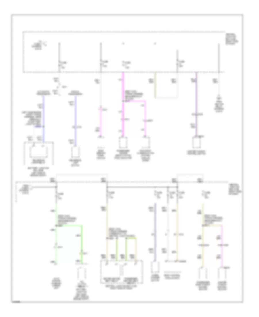
Power Distribution Wiring Diagram (4 of 5) for Ford Fiesta Titanium 2013
 https://portal-diagnostov.com/license.html
Automotive Electricians Portal FZCO
Automotive Electricians Portal FZCO
https://portal-diagnostov.com/license.html
https://portal-diagnostov.com/license.html
Automotive Electricians Portal FZCO
Automotive Electricians Portal FZCOList of elements for Power Distribution Wiring Diagram (4 of 5) for Ford Fiesta Titanium 2013:
- (instrument panel wiring harness, near breakout to instrument panel cluster) s230
- (w/ intelligent access) smart keyless entry accessory relay
- (w/ intelligent access) smart keyless entry ignition relay
- A/t
- Acc
- C175b
- C210
- C212
- C3503b
- C3503c
- C4321a
- Central junction box (cjb) (right side of dash)
- Floor shifter
- From central junction box (diagram 3 of 5)
- From smart keyless entry accessory relay (diagram 4 of 5)
- From splice s259 (diagram 2 of 5)
- Fuse 7.5a
- G201 (left side of dash)
- G301 (under front passenger's seat)
- Ignition switch (w/o intelligent access)
- Instrument panel cluster (ipc)
- Interior lights system
- Lock
- Off
- Park detect sw
- Powertrain control module (pcm)
- Red
- Remote function actuator (rfa) module (w/ intelligent access)
- Run
- Run/acc output
- S218
- S253 (body main red wiring harness, in breakout to central junction box)
- S256
- Ssb 1
- Ssb 2
- Start
- Start/run output
- Start/stop switch
- Sw 1
- Sw 2
- Tire pressure monitor/ vehicle security module (tpm/vsm)
- To central junction box (diagram 4 of 5)
- W/ intelligent access
- W/o intelligent access
Power Distribution Wiring Diagram (5 of 5) for Ford Fiesta Titanium 2013
 https://portal-diagnostov.com/license.html
Automotive Electricians Portal FZCO
Automotive Electricians Portal FZCO
https://portal-diagnostov.com/license.html
https://portal-diagnostov.com/license.html
Automotive Electricians Portal FZCO
Automotive Electricians Portal FZCOList of elements for Power Distribution Wiring Diagram (5 of 5) for Ford Fiesta Titanium 2013:
- (body main wiring harness, in breakout to central junction box) s254
- (body main wiring harness, near breakout to c214) s261
- (body main wiring harness, near breakout to c340) s310
- (body main wiring harness, near breakout to c340) s311
- (left side engine compt wiring harness, near breakout to battery junction box) s121
- A/c clutch relay
- A15 c339
- Auto dimming interior mirror unit
- Automatic tranmission
- Battery junction box (bjb) (left side of engine compt)
- Body control module (bcm)
- C133
- C211
- C212
- C213
- C214
- C2280b
- C3007
- C339 b14
- C340 a15
- C504a
- C504c
- Central junction box (cjb) (right side of dash)
- Driver heated seat relay
- From fuse 6 l (diagram 5 of 5)
- From ignition relay (diagram 2 of 5)
- Fuse 10a
- Fuse 15a
- Fuse 20a
- Fuse 30a
- Fuse 7.5a
- Manual tranmission
- Master window control switch
- Occupant classification system module (ocsm)
- Passenger air bag deactivation (pad) indicator
- Passenger heated seat relay
- Passenger side window control switch
- Reversing lamp switch
- Reversing lamps relay
- Roof opening panel module
- To fuse 4 (diagram 5 of 5)
- Wiper/ washer switch

 Čeština
 Dansk
Dansk Deutsch
 Ελληνικά
 English
 English
 Español
 Suomi
Suomi Français
 Français
 Hrvatski
 Magyar
 Italiano
 日本語
日本語 한국어
한국어 Nederlands
 Polski
 Português
 Português
 Română
 Русский
 Slovenčina
 Slovenščina
 Svenska
 Türkçe
 中文 (中国)
