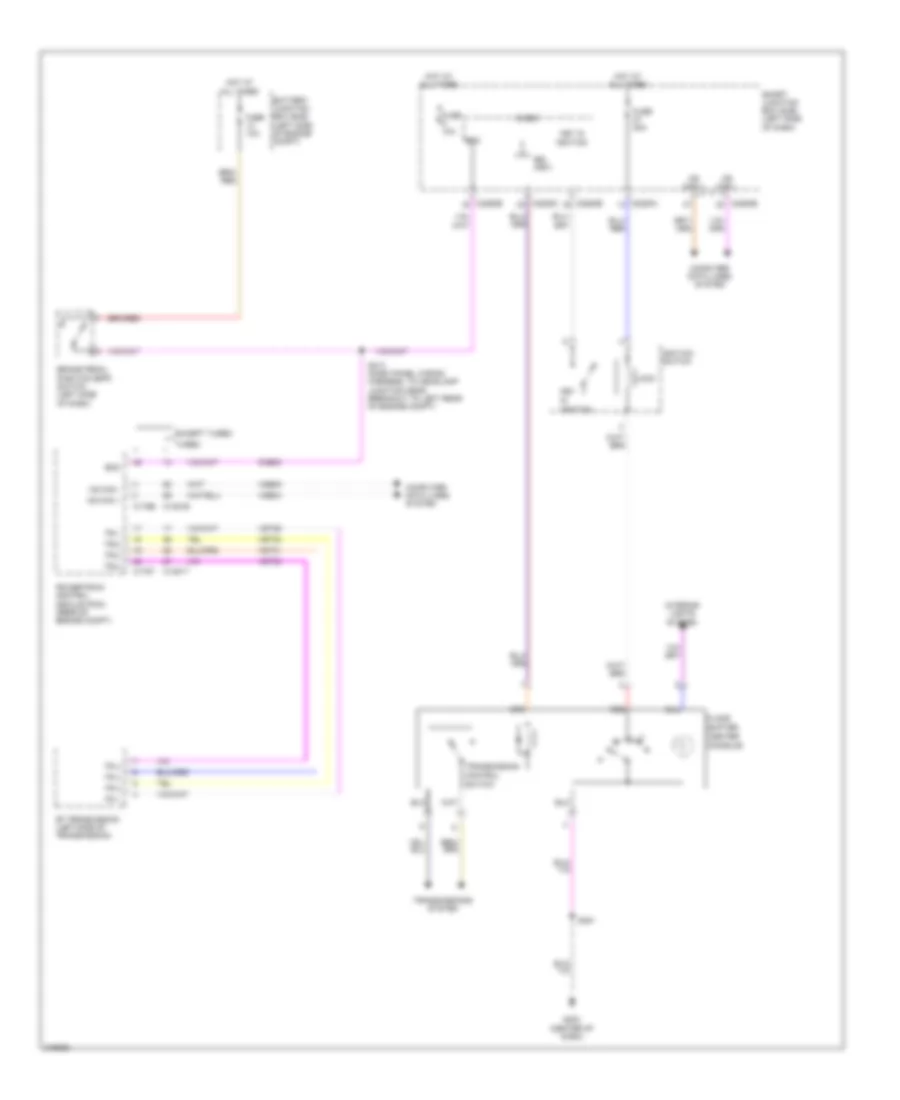
SHIFT INTERLOCK
Shift Interlock Wiring Diagram for Ford Flex SE 2010
 https://portal-diagnostov.com/license.html
Automotive Electricians Portal FZCO
Automotive Electricians Portal FZCO
https://portal-diagnostov.com/license.html
https://portal-diagnostov.com/license.html
Automotive Electricians Portal FZCO
Automotive Electricians Portal FZCO
List of elements for Shift Interlock Wiring Diagram for Ford Flex SE 2010:
- (center
- 6f transmission (left side of transmission)
- Battery junction box (bjb) (left side of engine compt)
- Boo
- Brake pedal position (bpp) switch (left side of dash)
- Bsi (fet)
- C1381b
- C1381t
- C175b
- C175t
- C2280a
- C2280b
- C2280c
- Ccb08
- Computer data lines system
- Console)
- Control
- Except turbo
- Floor
- Fuse 10a
- Fuse 20a
- G203 (center of dash)
- Hot at all times
- Hs can +
- Hs can -
- Ignition
- Ignition switch
- Interior lights system
- Key
- Key in ignition
- Lock
- Micro
- Ms can +
- Ms can -
- N d
- Powertrain control module (pcm) (rear of engine compt)
- Red
- S213 (dash panel wiring harness, to headlamp junction near breakout to left rear of engine compt)
- S381
- Shifter
- Smart junction box (sjb) (left side of dash)
- Switch
- Tr 1
- Tr 2
- Tr 3
- Tr 4
- Tr-1
- Tr-2
- Tr-3
- Tr-4
- Transmission
- Transmissions system
- Turbo
- Vdb04
- Vdb05
- Vet29
- Vet30
- Vet31
- Vet32
 Čeština
 Dansk
Dansk Deutsch
 Ελληνικά
 English
 English
 Español
 Suomi
Suomi Français
 Français
 Hrvatski
 Magyar
 Italiano
 日本語
日本語 한국어
한국어 Nederlands
 Polski
 Português
 Português
 Română
 Русский
 Slovenčina
 Slovenščina
 Svenska
 Türkçe
 中文 (中国)
 עברית
עברית
