SUPPLEMENTAL RESTRAINTS
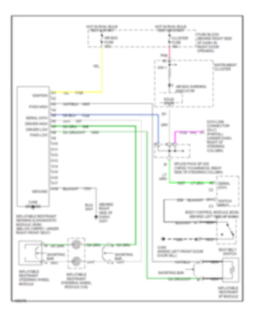
Supplemental Restraint Wiring Diagram for Oldsmobile Intrigue GL 2000
 https://portal-diagnostov.com/license.html
Automotive Electricians Portal FZCO
Automotive Electricians Portal FZCO
https://portal-diagnostov.com/license.html
https://portal-diagnostov.com/license.html
Automotive Electricians Portal FZCO
Automotive Electricians Portal FZCO
List of elements for Supplemental Restraint Wiring Diagram for Oldsmobile Intrigue GL 2000:
- (behind right side of dash) g201
- A10
- A11
- A12
- A13
- A14
- A15
- A16
- A17
- A18
- Air bag fuse 15a
- Air bag warning indicator
- B11
- Body control module (bcm) (behind left side of dash)
- Case ground
- Cluster fuse 10a
- Data link connector (dlc) (partial) (under dash, right of steering column)
- Driver high
- Driver low
- Fuse block (behind right side of dash, in right door opening)
- G309 (inside left front door door sill)
- Ground
- Hot in run, bulb test & start
- Hot in run, bulb test or start
- Ign 1
- Ignition
- Inflatable restraint i/p module
- Inflatable restraint sensing & diagnostic module (sdm) (below carpet, under right front seat)
- Inflatable restraint steering wheel module
- Inflatable restraint steering wheel module coil
- Instrument cluster
- Nca
- Pass high
- Pass low
- Pnk
- Seat belt switch
- Serial data
- Shorting bar
- Solid state
- Splice pack sp 205 (taped to harness, right side of steering column)
- Switch input
 Čeština
 Dansk
Dansk Deutsch
 Ελληνικά
 English
 English
 Español
 Suomi
Suomi Français
 Français
 Hrvatski
 Magyar
 Italiano
 日本語
日本語 한국어
한국어 Nederlands
 Polski
 Português
 Português
 Română
 Русский
 Slovenčina
 Slovenščina
 Svenska
 Türkçe
 中文 (中国)
 עברית
עברית
