AIR CONDITIONING
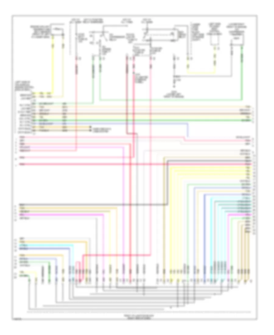
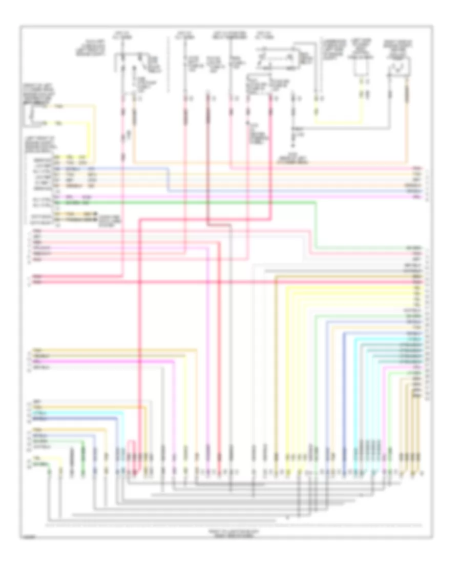
Automatic A/C Wiring Diagram, Except Hybrid (1 of 4) for GMC Yukon Denali 2013
 https://portal-diagnostov.com/license.html
Automotive Electricians Portal FZCO
Automotive Electricians Portal FZCO
https://portal-diagnostov.com/license.html
https://portal-diagnostov.com/license.html
Automotive Electricians Portal FZCO
Automotive Electricians Portal FZCO
List of elements for Automatic A/C Wiring Diagram, Except Hybrid (1 of 4) for GMC Yukon Denali 2013:
- (bottom right of hvac module) blower motor control module
- (headliner harness, 105 cm from left sunshade lamp breakout)
- (right front corner of dash) g200
- (under right side of hvac module) blower motor
- 4b7
- 5v ref
- A/c on ind
- A/c on switch
- Air temp
- Air tmp
- Amb tmp
- Ambient light/ sunload sensor assembly (top center of dash)
- B (+)
- Blwr spd
- Computer data lines system
- Defogger system
- Dfrst val
- Duct)
- Evaporator temperature sensor (top right side of hvac assembly)
- Fresh air ind
- Fresh air request switch
- Front defogger ind
- Front defogger switch
- Front inside air temperature sensor (left front of headliner)
- G200 (right front corner of dash)
- G201 (left end of dash)
- Gmlan l
- Gnd
- Ground
- Hvac ambient air temperature sensor (right front of engine compt)
- Hvac control module
- Ign volt
- J203
- J206 (instrument panel harness, approximately 14 cm from x207 breakout)
- J325
- J328
- L air tmp
- Left i/p junction block (left end of dash)
- Left temperature control
- Lf sunld
- Logic
- Long wheel base
- Low ref
- Mode ctrl
- Mode down switch
- Mode up switch
- Pass sunld
- Pnk
- Power distribution system
- R air tmp
- Rear defogger ind
- Rear defogger switch
- Recir ctrl
- Recirc
- Recircu- lation ind
- Recircu- lation switch
- Red
- Rer defg
- Right i/p junction block (right end of dash)
- Right temperature control
- Sens sig
- Short wheel base
- Sns sig
- Spd ctrl
- Sw sig
- Tan
- Temp sig
- Upper auxiliary air temperature sensor (in auxiliary hvac module upper duct)
- Upper left air temperature sensor (top left center of dash)
- Upper right air temperature sensor (top right center of dash)
- X103
- X11
- X207
- X403
- X407
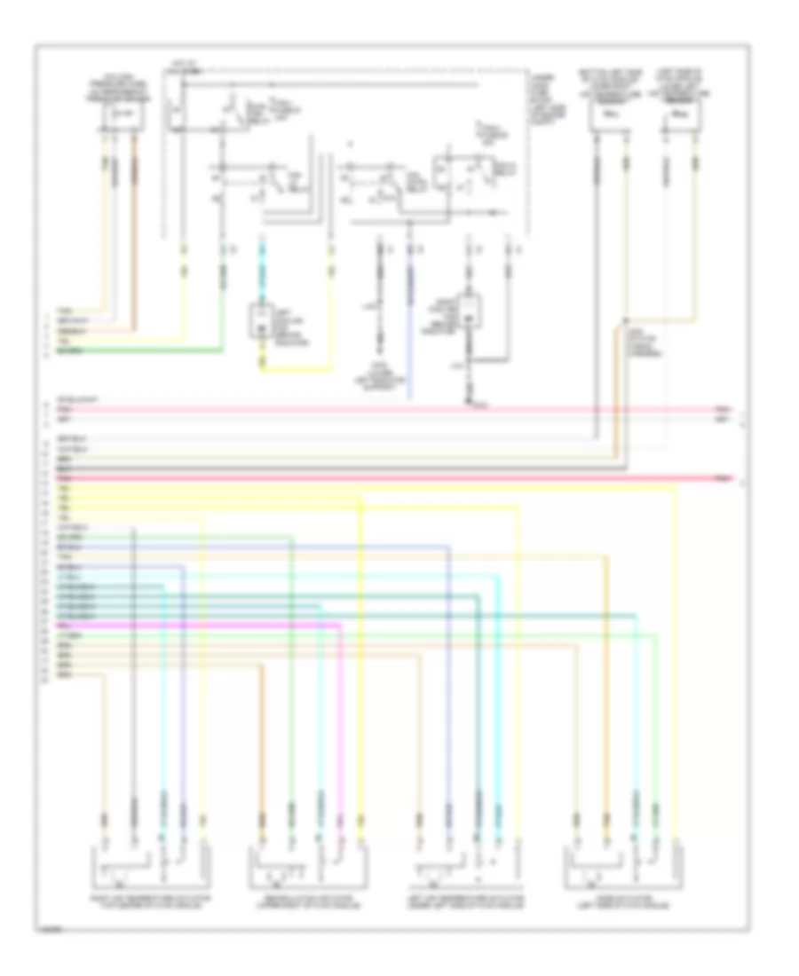
Automatic A/C Wiring Diagram, Except Hybrid (2 of 4) for GMC Yukon Denali 2013
 https://portal-diagnostov.com/license.html
Automotive Electricians Portal FZCO
Automotive Electricians Portal FZCO
https://portal-diagnostov.com/license.html
https://portal-diagnostov.com/license.html
Automotive Electricians Portal FZCO
Automotive Electricians Portal FZCOList of elements for Automatic A/C Wiring Diagram, Except Hybrid (2 of 4) for GMC Yukon Denali 2013:
- (left side of dash) body control module (bcm)
- (left side of fan shroud) engine control module (ecm)
- (lower right front of engine) a/c compressor clutch
- 4a1
- 4a2
- 4a3
- 4a4
- 4a5
- 4a6
- 4b2
- 4b3
- 4b5
- 4b6
- 5-volt ref
- A/c cmprsr fuse 17 10a
- A/c compressor/ relay
- Aux hvac-ign fuse 48 10a
- Coil ctrl
- Computer data lines system
- Data bus+
- Data bus-
- E x4
- Engine coolant temperature (ect) sensor (front of left cylinder head) b
- G102 (lower left front of engine)
- Hot at all times
- Hot w/ pwr/trn relay energized
- Hvac batt fuse 39 10a
- Hvac blwr fuse 70 40a
- Hvac-ign fuse 55 10a
- J219 (w/ heated steering wheel)
- Low ref
- Pnk
- Red
- Right i/p junction block (right end of dash)
- Rly ctrl
- Run/ crank relay
- Sens sig
- Tan
- Under- hood fuse block (left side of engine compt)
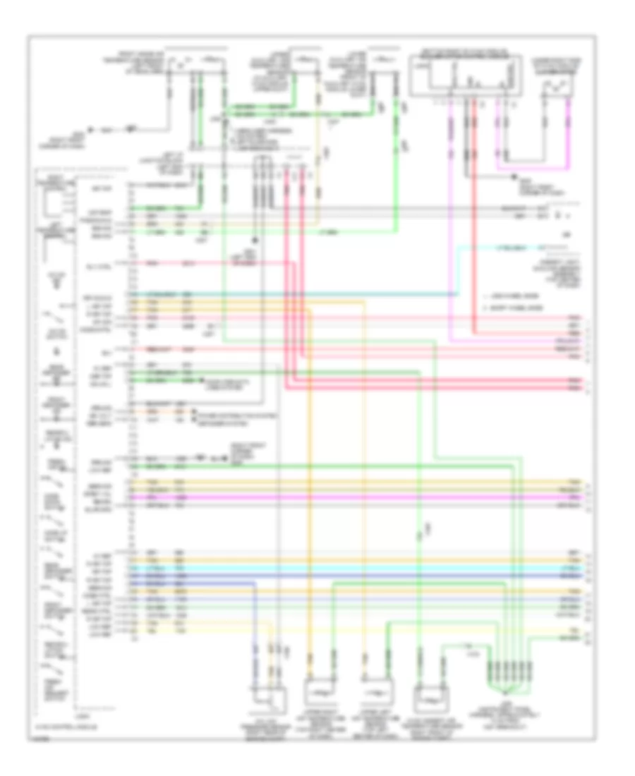
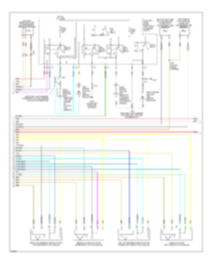
Automatic A/C Wiring Diagram, Except Hybrid (3 of 4) for GMC Yukon Denali 2013
 https://portal-diagnostov.com/license.html
Automotive Electricians Portal FZCO
Automotive Electricians Portal FZCO
https://portal-diagnostov.com/license.html
https://portal-diagnostov.com/license.html
Automotive Electricians Portal FZCO
Automotive Electricians Portal FZCOList of elements for Automatic A/C Wiring Diagram, Except Hybrid (3 of 4) for GMC Yukon Denali 2013:
- (a/c high pressure hose) a/c refrigerant pressure sensor
- (bottom left side of hvac module) lower right air temperature sensor
- (left side of hvac module) lower left air temperature sensor
- 87a
- Fan cntrl relay
- Fan hi relay
- Fan lo relay
- Fan-1 fuse 57 40a
- Fan-2 fuse 60 40a
- G100 (lower left radiator support)
- G101
- Hot at all times
- J100
- J101
- J242 (in hvac wiring harness)
- Left air temperature actuator (under left side of hvac module)
- Left cooling fan (behind radiator)
- Mode actuator (left side of hvac module)
- Pnk
- Pwr/ trn relay
- Recirculation actuator (upper right of hvac module)
- Right air temperature actuator (top center of hvac module)
- Right cooling fan (behind radiator)
- Tan
- Under- hood fuse block (left side of engine compt)
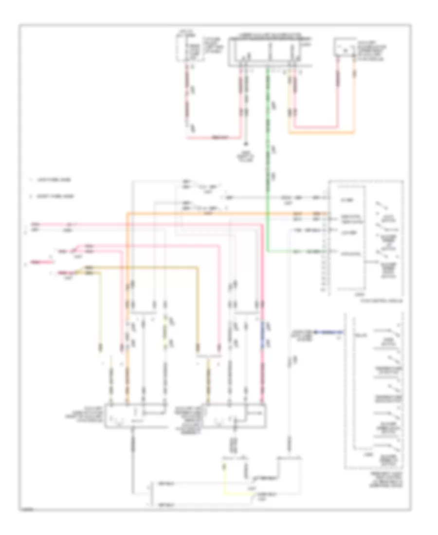
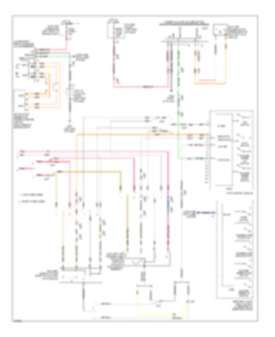
Automatic A/C Wiring Diagram, Except Hybrid (4 of 4) for GMC Yukon Denali 2013
 https://portal-diagnostov.com/license.html
Automotive Electricians Portal FZCO
Automotive Electricians Portal FZCO
https://portal-diagnostov.com/license.html
https://portal-diagnostov.com/license.html
Automotive Electricians Portal FZCO
Automotive Electricians Portal FZCOList of elements for Automatic A/C Wiring Diagram, Except Hybrid (4 of 4) for GMC Yukon Denali 2013:
- (or pnk)
- (under auxiliary blower motor) auxiliary blower motor control module
- 5v ref
- A10
- A11
- Auto switch
- Auxiliary air temperature actuator (rear of auxiliary hvac module assembly)
- Auxiliary blower motor (upper front of auxiliary hvac module)
- Auxiliary mode actuator (front of auxiliary hvac module)
- Blower speed down switch
- Blower speed up switch
- Computer data lines system
- G402 (right "d" pillar)
- Gmlan
- Gnd
- Hot at all times
- Hvac control module
- I/p fuse block (left end of dash)
- Logic
- Long wheel base
- Low ref
- Mde cntrl
- Mode switch
- Mtr cntrl
- Pnk
- Rear hvac fuse 30a
- Rear seat audio (rsa) control (w/ rear seat & earphone jacks)
- Short wheel base
- Spd ctrl
- Temp cntrl
- Temperature down switch
- Temperature up switch
- X202
- X207
- X407
Automatic A/C Wiring Diagram, Hybrid (1 of 4) for GMC Yukon Denali 2013
 https://portal-diagnostov.com/license.html
Automotive Electricians Portal FZCO
Automotive Electricians Portal FZCO
https://portal-diagnostov.com/license.html
https://portal-diagnostov.com/license.html
Automotive Electricians Portal FZCO
Automotive Electricians Portal FZCOList of elements for Automatic A/C Wiring Diagram, Hybrid (1 of 4) for GMC Yukon Denali 2013:
- (bottom right of hvac module) blower motor control module
- (headliner harness, 105 cm from left sunshade lamp breakout)
- (right front corner of dash) g200
- (under right side of hvac module) blower motor
- 5v ref
- A/c low pressure sensor (right rear of engine compt)
- A/c on ind
- A/c on switch
- Air temp
- Air tmp
- Amb tmp
- Ambient light/ sunload sensor assembly (top center of dash)
- B(+)
- Blwr spd
- Computer data lines system
- Defogger system
- Dfrst val
- Drv sunld
- Fresh air ind
- Fresh air request switch
- Front defogger ind
- Front defogger switch
- Front inside air temperature sensor (left front of headliner)
- G200 (right front corner of dash)
- G201 (left end of dash)
- Gmlan l
- Gnd
- Ground
- Hvac ambient air temperature sensor (right front of engine compt)
- Hvac control module
- Ign volt
- J203
- J206 (instrument panel harness, approximately 14 cm from x207 breakout)
- J325
- J328
- L air tmp
- Left i/p junction block (left end of dash)
- Left temperature control
- Logic
- Long wheel base
- Low ref
- Mode cntrl
- Mode ctrl
- Mode down switch
- Mode up switch
- Pass sunld
- Pnk
- Power distribution system
- R air tmp
- Rear defogger ind
- Rear defogger switch
- Recir ctrl
- Recirc
- Recircu- lation ind
- Recircu- lation switch
- Red
- Rer defg
- Right temperature control
- Rly ctrl
- Sens sig
- Short wheel base
- Sns sig
- Spd ctrl
- Sw sig
- Tan
- Upper auxiliary air temperature sensor (in auxiliary a hvac module upper duct)
- Upper left air temperature sensor (top left center of dash)
- Upper right air temperature sensor (top right center of dash)
- X103
- X11
- X150
- X207
- X403
- X407
Automatic A/C Wiring Diagram, Hybrid (2 of 4) for GMC Yukon Denali 2013
 https://portal-diagnostov.com/license.html
Automotive Electricians Portal FZCO
Automotive Electricians Portal FZCO
https://portal-diagnostov.com/license.html
https://portal-diagnostov.com/license.html
Automotive Electricians Portal FZCO
Automotive Electricians Portal FZCOList of elements for Automatic A/C Wiring Diagram, Hybrid (2 of 4) for GMC Yukon Denali 2013:
- (front of left cylinder head) engine coolant temperature (ect) sensor
- (left front of engine compt) engine control module (ecm)
- (left side of dash) body control module (bcm)
- (right side of engine compt) heater coolant pump
- 4a1
- 4a2
- 4a3
- 4a4
- 4a5
- 4a6
- 4b2
- 4b3
- 4b5
- 4b6
- 5v ref 1
- Aux hvac-ign fuse 48 10a
- Auxiliary fuse block (left front of engine compt)
- Cab htr pump fuse 4 10a
- Cab htr pump relay
- Computer data lines system
- Data bus+
- Data bus-
- E x4
- Eng fuse 4 15a
- G102 (rear of left cylinder head)
- Hot at all times
- Hot w/ pwr/trn relay energized
- Hvac batt fuse 39 10a
- Hvac blwr fuse 70 40a
- Hvac-ign fuse 55 10a
- J219 (w/ heated steering wheel)
- Low ref
- Pnk
- Red
- Right i/p junction block (right end of dash)
- Rly ctrl
- Run/ crank relay
- Sens sig
- Tan
- Underhood fuse block (left side of engine compt)
- X150
Automatic A/C Wiring Diagram, Hybrid (3 of 4) for GMC Yukon Denali 2013
 https://portal-diagnostov.com/license.html
Automotive Electricians Portal FZCO
Automotive Electricians Portal FZCO
https://portal-diagnostov.com/license.html
https://portal-diagnostov.com/license.html
Automotive Electricians Portal FZCO
Automotive Electricians Portal FZCOList of elements for Automatic A/C Wiring Diagram, Hybrid (3 of 4) for GMC Yukon Denali 2013:
- (a/c high pressure hose) a/c refrigerant pressure sensor
- (bottom left side of hvac module) lower right air temperature sensor
- (forward lamp harness, in breakout to left engine cooling fan resistor)
- (left side of hvac module) lower left air temperature sensor
- 87a
- Auxiliary fuse block (left front of engine compt)
- Fan cntrl relay
- Fan hi relay
- Fan lo relay
- Fan mid 1 relay
- Fan mid 2 relay
- Fan-1 fuse 40a
- Fan-2 fuse 40a
- G100 (lower left radiator support)
- G101
- Hot at all times
- J100
- J101
- J162
- J163 (forward lamp harness, 5 cm from left cooling fan breakout)
- J242 (in hvac wiring harness)
- Left air temperature actuator (under left side of hvac module)
- Left engine cooling fan (behind radiator)
- Left engine cooling fan resistor (top left corner of cooling fan shroud)
- Mode actuator (left side of hvac module)
- Pnk
- Recirculation actuator (upper right of hvac module)
- Right air temperature actuator (top center of hvac module)
- Right engine cooling fan (behind radiator)
- Right engine cooling fan resistor (top right corner of cooling fan shroud)
- Tan
- X127
Automatic A/C Wiring Diagram, Hybrid (4 of 4) for GMC Yukon Denali 2013
 https://portal-diagnostov.com/license.html
Automotive Electricians Portal FZCO
Automotive Electricians Portal FZCO
https://portal-diagnostov.com/license.html
https://portal-diagnostov.com/license.html
Automotive Electricians Portal FZCO
Automotive Electricians Portal FZCOList of elements for Automatic A/C Wiring Diagram, Hybrid (4 of 4) for GMC Yukon Denali 2013:
- (lower right front of engine) a/c compressor
- (or pnk)
- (under auxiliary blower motor) auxiliary blower motor control module
- 300v+
- 300v-
- 5v ref
- A10
- A11
- Accm fuse 3 15a
- Auto switch
- Auxiliary air temperature actuator (rear of auxiliary hvac module assembly)
- Auxiliary blower motor (upper front of auxiliary hvac module)
- Auxiliary fuse block (left front of engine compt)
- Auxiliary mode actuator (front of auxiliary hvac module)
- Blower speed down switch
- Blower speed up switch
- Computer data lines system
- Drive motor generator power inverter module (right rear of engine compt)
- G201 (left end of dash)
- G402 (right "d" pillar)
- Gmlan
- Gnd
- Ground
- Hot at all times
- Hvac control module
- I/p fuse block (left end of dash)
- Left i/p junction block (left end x1
- Logic
- Long wheel base
- Low ref
- Mde cntrl
- Mode switch
- Mtr cntrl
- Of dash)
- Off switch
- Pnk
- Rear hvac fuse 30a
- Rear seat audio (rsa) control (w/ rear seat & earphone jacks)
- Serial data
- Short wheel base
- Spd ctrl
- Temp cntrl
- Temperature down switch
- Temperature up switch
- X150
- X202
- X207
- X407

 Čeština
 Dansk
Dansk Deutsch
 Ελληνικά
 English
 English
 Español
 Suomi
Suomi Français
 Français
 Hrvatski
 Magyar
 Italiano
 日本語
日本語 한국어
한국어 Nederlands
 Polski
 Português
 Português
 Română
 Русский
 Slovenčina
 Slovenščina
 Svenska
 Türkçe
 中文 (中国)
