SUPPLEMENTAL RESTRAINTS
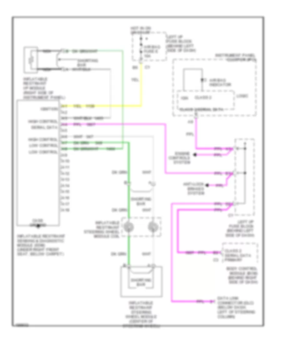
Supplemental Restraints Wiring Diagram for Pontiac Grand Am GT 2005
 https://portal-diagnostov.com/license.html
Automotive Electricians Portal FZCO
Automotive Electricians Portal FZCO
https://portal-diagnostov.com/license.html
https://portal-diagnostov.com/license.html
Automotive Electricians Portal FZCO
Automotive Electricians Portal FZCO
List of elements for Supplemental Restraints Wiring Diagram for Pontiac Grand Am GT 2005:
- A10
- A11
- A12
- A13
- A14
- A15
- A16
- A17
- A18
- Air bag fuse e 10a
- Air bag indicator
- Anti-lock brakes system
- Body control module (bcm) (behind right side of dash)
- Case ground
- Class 2
- Class 2 serial data
- Class 2 serial data primary
- Data link connector (dlc) (below dash, left of steering column)
- Engine controls system
- High control
- Hot in on or start
- Ign
- Ignition
- Inflatable restraint i/p module (right side of instrument panel)
- Inflatable restraint sensing & diagnostic module (sdm) (under right front seat, below carpet)
- Inflatable restraint steering wheel module (center of steering wheel)
- Inflatable restraint steering wheel module coil
- Instrument panel cluster (ipc)
- Left i/p fuse block (behind left side of dash)
- Logic
- Low control
- Nca
- Serial data
- Shorting bar
 Čeština
 Dansk
Dansk Deutsch
 Ελληνικά
 English
 English
 Español
 Suomi
Suomi Français
 Français
 Hrvatski
 Magyar
 Italiano
 日本語
日本語 한국어
한국어 Nederlands
 Polski
 Português
 Português
 Română
 Русский
 Slovenčina
 Slovenščina
 Svenska
 Türkçe
 中文 (中国)
 עברית
עברית
