ANTI-LOCK BRAKES
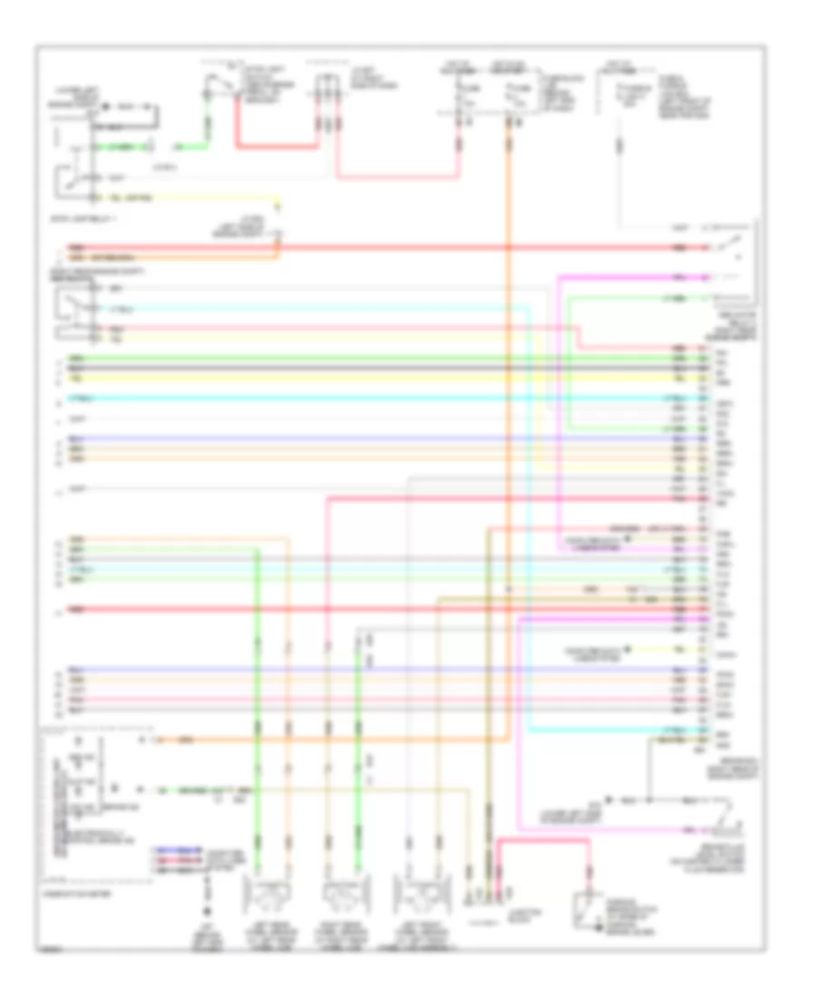
Anti-lock Brakes Wiring Diagram, Except Hybrid with Traction Control (1 of 2) for Nissan Altima S 2011
 https://portal-diagnostov.com/license.html
Automotive Electricians Portal FZCO
Automotive Electricians Portal FZCO
https://portal-diagnostov.com/license.html
https://portal-diagnostov.com/license.html
Automotive Electricians Portal FZCO
Automotive Electricians Portal FZCO
List of elements for Anti-lock Brakes Wiring Diagram, Except Hybrid with Traction Control (1 of 2) for Nissan Altima S 2011:
- (behind right end of dash) m61
- 12m m5
- 1p e6
- 67g m1
- 75g
- Abs actuator & electric unit (control unit) (right rear of engine compt)
- Abs/tcs/vdc control unit
- Actuator
- Asr aus
- B10
- B43
- Bls
- Can-h
- Can-l
- Can-m2
- Can-p2
- Computer data lines system
- Diag-k
- Dp fl
- Dp fr
- Dp rl
- Dp rr
- Ds fl
- Ds fr
- Ds rl
- Ds rr
- E18
- E29
- E30
- E33
- E44
- E46
- E47
- E49
- E6 8p
- Fl in
- Fl out
- Fr in
- Fr out
- Fuse & fusible link box (left front of engine compt, near ipdm e/r)
- Fuse 10a
- Fuse block (j/b) (behind left end of dash)
- Fusible link f 50a
- Fusible link g 30a
- Gnd
- Hot at all times
- Hot in on or start
- Hsv 1
- Hsv 2
- Interior lights system
- Ipdm e/r (intelligent power distribution module engine room) (left side of engine compt)
- J/c m01 (behind left side of dash)
- Junction block
- Left front wheel sensor (at left front wheel hub assembly)
- Left rear wheel sensor (at left rear hub assembly)
- Motor
- Motor relay
- Pnk
- Red
- Relay unit
- Right front wheel sensor (at right front wheel hub assembly)
- Right rear wheel sensor (at right rear hub assembly)
- Rl in
- Rl out
- Rr in
- Rr out
- Solenoid valve relay
- U sv1
- U sv2
- Vdc off switch
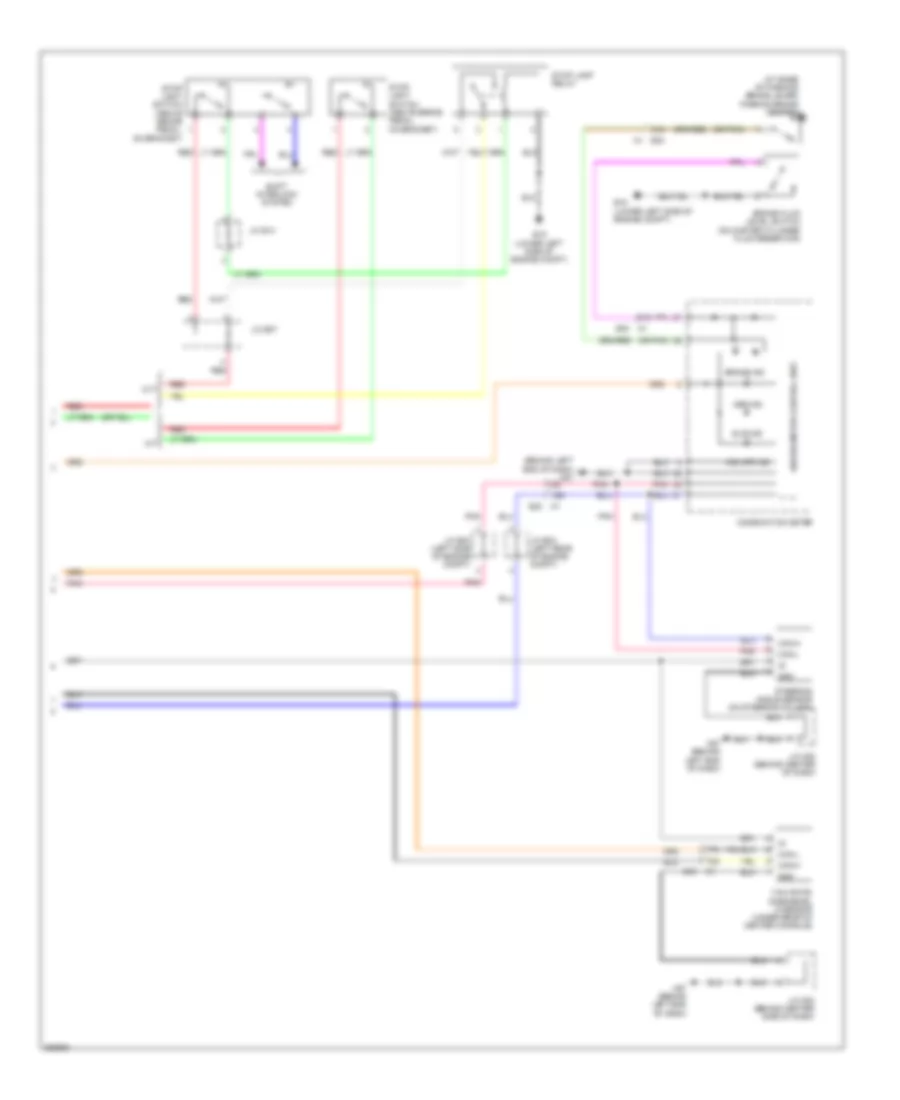
Anti-lock Brakes Wiring Diagram, Except Hybrid with Traction Control (2 of 2) for Nissan Altima S 2011
 https://portal-diagnostov.com/license.html
Automotive Electricians Portal FZCO
Automotive Electricians Portal FZCO
https://portal-diagnostov.com/license.html
https://portal-diagnostov.com/license.html
Automotive Electricians Portal FZCO
Automotive Electricians Portal FZCOList of elements for Anti-lock Brakes Wiring Diagram, Except Hybrid with Traction Control (2 of 2) for Nissan Altima S 2011:
- (at base of parking brake lever) parking brake switch
- (behind left end of dash) m57
- (or pnk)
- 15g
- 31g
- 70g
- 77g
- Abs ind
- Brake fluid level switch (on master cylinder fluid reservoir)
- Brake ind
- Can-h
- Can-l
- Combination meter
- Cvt
- E15 (lower left side of engine compt)
- E30
- E30 m1
- Gnd
- J/c e03 (left rear of engine compt)
- J/c e04 (left side of engine compt)
- J/c e07
- J/c e14
- J/c m02 (behind center of dash)
- J/c m02 (behind center side of dash)
- M/t
- M57 (behind left end of dash)
- Pnk
- Red
- Shift interlock system
- Slip ind
- Steering angle sensor (on steering column)
- Stop lamp relay
- Stop light switch (above brake pedal, on bracket)
- Unified meter control unit
- Vdc off ind
- Yaw rate/ side/decel g sensor (under rear of center console)
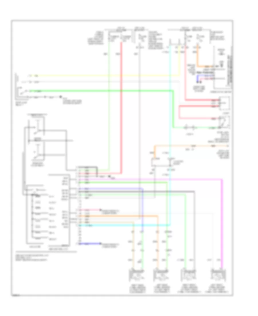
Anti-lock Brakes Wiring Diagram, Except Hybrid without Traction Control for Nissan Altima S 2011
 https://portal-diagnostov.com/license.html
Automotive Electricians Portal FZCO
Automotive Electricians Portal FZCO
https://portal-diagnostov.com/license.html
https://portal-diagnostov.com/license.html
Automotive Electricians Portal FZCO
Automotive Electricians Portal FZCOList of elements for Anti-lock Brakes Wiring Diagram, Except Hybrid without Traction Control for Nissan Altima S 2011:
- (behind left end of dash) m57
- (w/ information display) unified meter control unit
- 12m m5
- 34g
- 8p e6
- Abs actuator & electric unit (control unit) (right rear of engine compt)
- Abs control unit
- Abs ind
- Actuator
- B10
- B43
- Bls
- Brake ind
- Can-h
- Can-l
- Combination meter
- Computer data lines system
- Data link connector (left side of dash)
- Diag-k
- Dp fl
- Dp fr
- Dp rl
- Dp rr
- Ds fl
- Ds fr
- Ds rl
- Ds rr
- E15 (lower left side of engine compt)
- E18
- E29
- E30
- E33
- E44
- E46
- Fl in
- Fl out
- Fr in
- Fr out
- Fuse & fusible link box (left front of engine compt, near ipdm e/r)
- Fuse 10a
- Fuse block (j/b) (behind left end of dash)
- Fusible link g 30a
- Fusible link i 40a
- Gnd
- Hot at all times
- Hot in on or start
- Ign
- Ipdm e/r (intelligent power distribution module engine room) (left side of engine compt)
- J/c e07
- J/c e14
- Junction block
- Left front wheel sensor (at left front wheel hub assembly)
- Left rear wheel sensor (at left rear hub assembly)
- Motor
- Motor relay
- Pnk
- Red
- Relay unit
- Right front wheel sensor (at right front wheel hub assembly)
- Right rear wheel sensor (at right rear hub assembly)
- Rl in
- Rl out
- Rr in
- Rr out
- Solenoid valve relay
- Stop lamp relay 1
- Stop light switch (w/ cvt) (above brake pedal, on bracket)
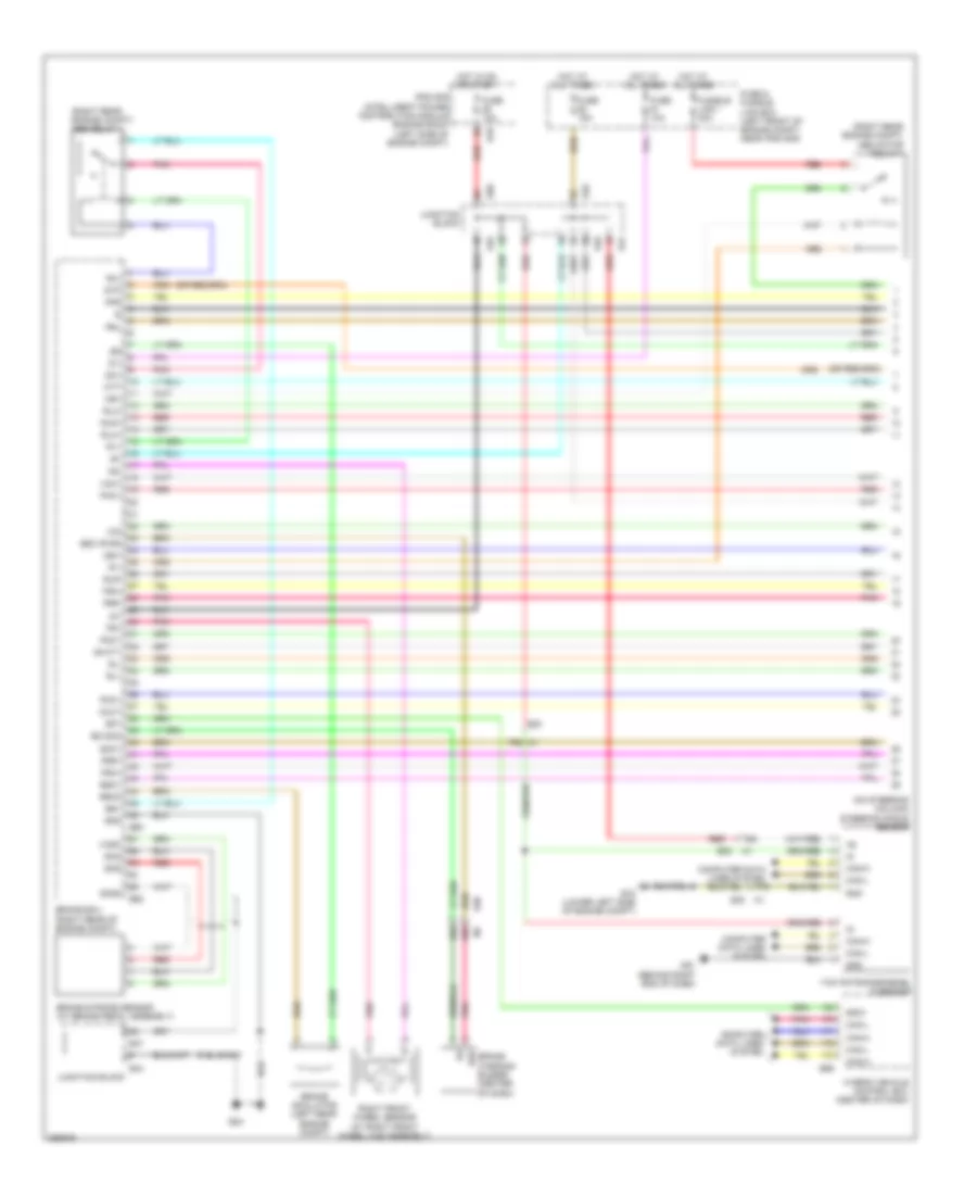
Anti-lock Brakes Wiring Diagram, Hybrid (1 of 3) for Nissan Altima S 2011
 https://portal-diagnostov.com/license.html
Automotive Electricians Portal FZCO
Automotive Electricians Portal FZCO
https://portal-diagnostov.com/license.html
https://portal-diagnostov.com/license.html
Automotive Electricians Portal FZCO
Automotive Electricians Portal FZCOList of elements for Anti-lock Brakes Wiring Diagram, Hybrid (1 of 3) for Nissan Altima S 2011:
- (on steering column) steering angle sensor
- (right rear engine compt) abs motor relay 1
- (right rear engine compt) abs relay 1
- 68g
- 69g
- 75g
- 76g m1
- 77g
- B+cty
- B2o
- Brake ecu (right rear of engine compt)
- Brake simulator (left rear engine compt)
- Brake stroke sensor (at brake pedal assembly)
- Brake warning buzzer (center of dash)
- Bs1
- Bso1
- Bso3
- Bz (sig)
- Bzo (pwr)
- Can-h
- Can-l
- Cbi1
- Cin
- Computer data lines system
- Cout
- Di1
- Do1
- E15 (lower left side of engine compt)
- E18
- E24
- E30
- E44
- E45
- E46
- E47
- E50
- E60
- E62
- E66
- Fr+
- Fr-
- Fra+
- Fra-
- Frr+
- Frr-
- Fuse & fusible link box (left front of engine compt, near ipdm e/r)
- Fuse 10a
- Fuse 15a
- Fusible link i 30a
- Gnd
- Hot at all times
- Hot in on or start
- Hybrid vehicle control ecu (center of dash)
- Ig1
- Ipdm e/r (intelligent power distribution module engine room) (left side of engine compt)
- Junction block
- M1 e30
- M61 (behind right end of dash)
- Mr1
- Mtt
- Pac1
- Pck1
- Pfr
- Pmc1
- Pnk
- Prl
- R1+
- R1-
- R3+
- Red
- Right front wheel sensor (at right front wheel hub assembly)
- Rl+
- Rl-
- Rla+
- Rla-
- Rlr+
- Rlr-
- Skg
- Sks
- Sks2
- Smc1
- Sp1
- Spd1
- Stp
- Vcm1
- Vcsk
- Yaw rate/side/decel g sensor
Anti-lock Brakes Wiring Diagram, Hybrid (2 of 3) for Nissan Altima S 2011
 https://portal-diagnostov.com/license.html
Automotive Electricians Portal FZCO
Automotive Electricians Portal FZCO
https://portal-diagnostov.com/license.html
https://portal-diagnostov.com/license.html
Automotive Electricians Portal FZCO
Automotive Electricians Portal FZCOList of elements for Anti-lock Brakes Wiring Diagram, Hybrid (2 of 3) for Nissan Altima S 2011:
- (in left "b" pillar) left front door switch
- +bcty
- 17j
- B109
- B117 (at right "c" pillar)
- B129
- Brake actuator (right rear engine compt)
- Brake capacitor (right side of luggage compt)
- Cty
- E24
- E44
- E45
- E46
- E71
- Ena
- Fail
- Gnd
- Junction block
- M10 b104
- Motor
- Out
- Out2
- Pnk
- Red
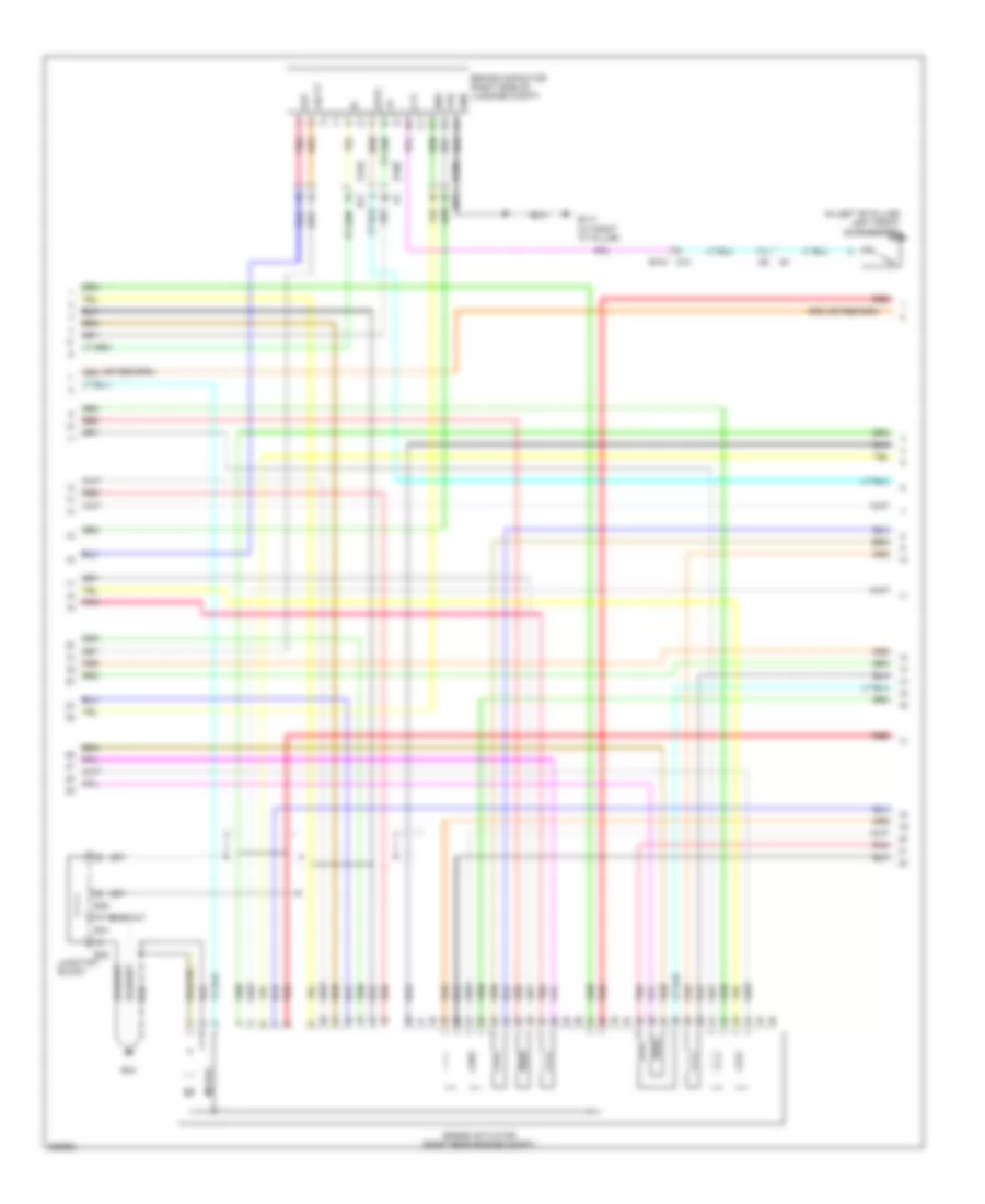
Anti-lock Brakes Wiring Diagram, Hybrid (3 of 3) for Nissan Altima S 2011
 https://portal-diagnostov.com/license.html
Automotive Electricians Portal FZCO
Automotive Electricians Portal FZCO
https://portal-diagnostov.com/license.html
https://portal-diagnostov.com/license.html
Automotive Electricians Portal FZCO
Automotive Electricians Portal FZCOList of elements for Anti-lock Brakes Wiring Diagram, Hybrid (3 of 3) for Nissan Altima S 2011:
- (lower left side of engine compt) e15
- (or pnk)
- (right rear engine compt) abs relay 2
- 12m
- 24g
- 74g
- Abs ind
- Abs motor relay 2 (right rear engine compt)
- B10
- B43
- Brake ecu (right rear of engine compt)
- Brake fluid level switch (on master cylinder fluid reservoir)
- Brake ind
- Bs02
- Bs2
- Can-h
- Can-l
- Cb12
- Combination meter
- Computer data lines system
- D12
- Do2
- E15 (lower left side of engine compt)
- E29
- E30
- E47
- E49
- E61
- Electronically control brake ind
- Fl+
- Fl-
- Fla+
- Fla-
- Flr+
- Flr-
- Fuse & fusible link box (left front of engine compt, near ipdm e/r)
- Fuse 10a
- Fuse block (j/b) (behind left end of dash)
- Fusible link h 50a
- Gnd
- Hot at all times
- Hot in on or start
- Ig2
- J/c e04 (left side of engine compt)
- J/c e07 (at right side of dash)
- J/c e14
- Junction block
- Lbl
- Left front wheel sensor (at left front
- Left rear wheel sensor (at left rear wheel hub)
- M1 e30
- M57 (behind left end of dash)
- Mr2
- Parking brake switch (at base of parking brake lever)
- Pck2
- Pfl
- Pkb
- Pmc2
- Pnk
- Prr
- R2+
- R2-
- R4+
- Red
- Right rear wheel sensor (at right rear wheel hub)
- Rr+
- Rr-
- Rra+
- Rra-
- Rrr+
- Rrr-
- Slip ind
- Smc2
- Stop lamp relay 1
- Stop light switch (above brake pedal, on bracket)
- Unified meter control unit (w/ information display)
- Vdc ind
- Vmc2
- Wheel hub assembly)

 Čeština
 Dansk
Dansk Deutsch
 Ελληνικά
 English
 English
 Español
 Suomi
Suomi Français
 Français
 Hrvatski
 Magyar
 Italiano
 日本語
日本語 한국어
한국어 Nederlands
 Polski
 Português
 Português
 Română
 Русский
 Slovenčina
 Slovenščina
 Svenska
 Türkçe
 中文 (中国)
