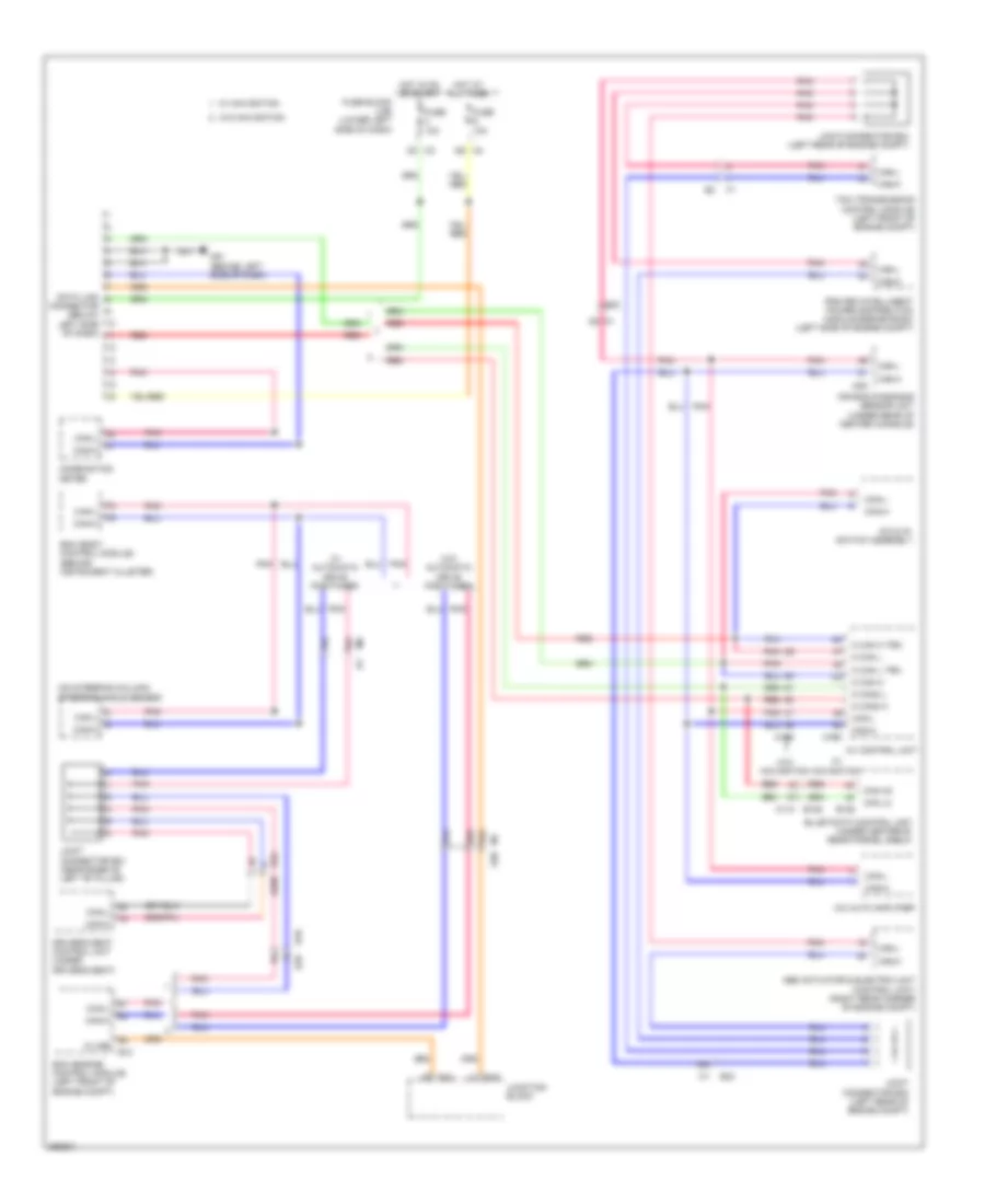
COMPUTER DATA LINES
Computer Data Lines Wiring Diagram for Nissan Maxima SV 2011
 https://portal-diagnostov.com/license.html
Automotive Electricians Portal FZCO
Automotive Electricians Portal FZCO
https://portal-diagnostov.com/license.html
https://portal-diagnostov.com/license.html
Automotive Electricians Portal FZCO
Automotive Electricians Portal FZCO
List of elements for Computer Data Lines Wiring Diagram for Nissan Maxima SV 2011:
- (on steering column) steering angle sensor
- 15g
- 15j
- 16j
- 34g
- 51g
- 52g
- 8g m1
- A/c & av switch assembly
- A/c auto amplifier
- Abs actuator & electric unit (control unit) (right rear corner of engine compt)
- Air bag diagnosis sensor unit (under rear of center console)
- Av control unit
- B10
- B125
- B208
- B32
- Bcm (body control module) (behind instrument cluster)
- Can h2
- Can l2
- Can-h
- Can-l
- Combination meter
- Connector (below left side of dash)
- Data link
- Driver's seat control unit (under driver's seat)
- E10
- E29
- E30
- E45
- E46
- Ecm (engine control module) (left front of engine compt)
- Fuse 10a
- Fuse block (j/b) (lower left side of dash)
- Hot at all times
- Hot in on or start
- Ipdm e/r (intelligent power distribution module engine room) (left side of engine compt)
- Joint connector b01 (near base of left "b" pillar)
- Joint connector e03 (left rear of engine compt)
- Joint connector e04 (left rear of engine compt)
- Junction block
- K-line
- M can h
- M can h trm
- M can l
- M can l trm
- M can2 h
- M can2 l
- M1 e30
- M110 b136
- M156
- M163
- M35
- M61 (behind left side of dash)
- Pnk
- Red
- Tcm (transmission control module) (left front of engine compt)
- W/ automatic drive positioner
- W/ navigation
- W/o automatic drive positioner
- W/o navigation
 Čeština
 Dansk
Dansk Deutsch
 Ελληνικά
 English
 English
 Español
 Suomi
Suomi Français
 Français
 Hrvatski
 Magyar
 Italiano
 日本語
日本語 한국어
한국어 Nederlands
 Polski
 Português
 Português
 Română
 Русский
 Slovenčina
 Slovenščina
 Svenska
 Türkçe
 中文 (中国)
 עברית
עברית
