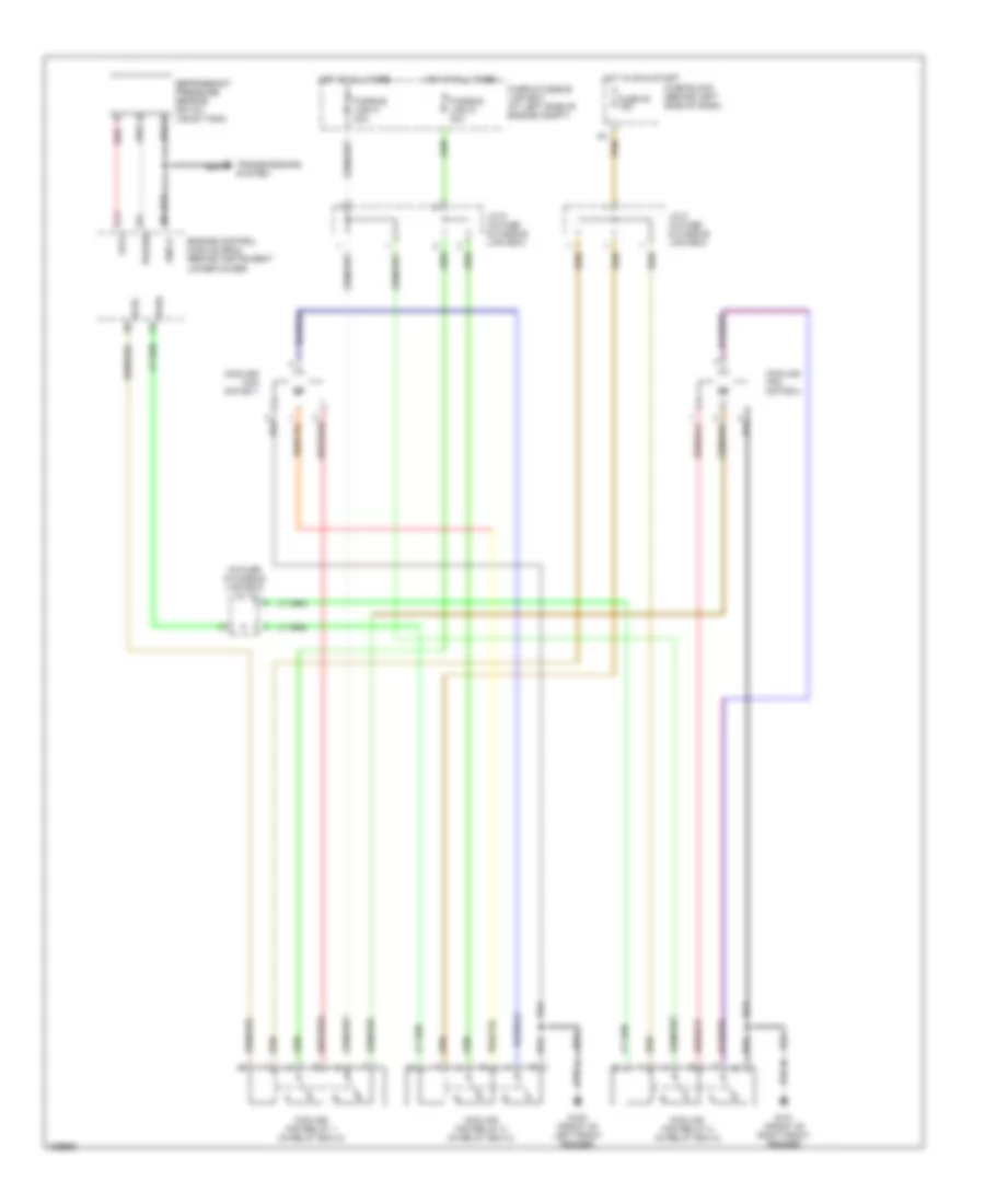
COOLING FAN
Cooling Fan Wiring Diagram for Nissan Maxima SE 2001
 https://portal-diagnostov.com/license.html
Automotive Electricians Portal FZCO
Automotive Electricians Portal FZCO
https://portal-diagnostov.com/license.html
https://portal-diagnostov.com/license.html
Automotive Electricians Portal FZCO
Automotive Electricians Portal FZCO
List of elements for Cooling Fan Wiring Diagram for Nissan Maxima SE 2001:
- (in fuse & fusible link box) j/c 10
- Avcc
- Cooling fan motor 1
- Cooling fan motor 2
- Cooling fan relay 1 (in relay box 2)
- Cooling fan relay 2 (in relay box 2)
- Cooling fan relay 3 (in relay box 2)
- Engine control module (ecm) (behind instrument lower cover)
- Fuse & fusible link box (at left side of engine compt)
- Fuse 20 15a
- Fuse block (behind left side of dash)
- Fusible link g 40a
- Fusible link h 40a
- G100 (front of left front fender)
- G101 (front of right front fender)
- Gnd-a
- Hot at all times
- Hot in on & start
- J/c 8 (in fuse & fusible link box)
- J/c 9 (in fuse & fusible link box)
- Pdpres
- Red
- Refrigerant pressure sensor (on a/c liquid tank)
- Rfrh
- Rfrl
- Transmissions system
 Čeština
 Dansk
Dansk Deutsch
 Ελληνικά
 English
 English
 Español
 Suomi
Suomi Français
 Français
 Hrvatski
 Magyar
 Italiano
 日本語
日本語 한국어
한국어 Nederlands
 Polski
 Português
 Português
 Română
 Русский
 Slovenčina
 Slovenščina
 Svenska
 Türkçe
 中文 (中国)
 עברית
עברית
