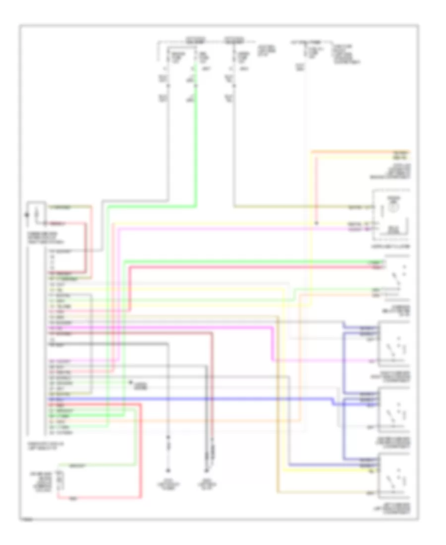
SUPPLEMENTAL RESTRAINTS
Supplemental Restraint Wiring Diagram for Mazda MX-3 1995
 https://portal-diagnostov.com/license.html
Automotive Electricians Portal FZCO
Automotive Electricians Portal FZCO
https://portal-diagnostov.com/license.html
https://portal-diagnostov.com/license.html
Automotive Electricians Portal FZCO
Automotive Electricians Portal FZCO
List of elements for Supplemental Restraint Wiring Diagram for Mazda MX-3 1995:
- Abs fuse 10a
- Air bag ind
- Air bag module (steering column)
- Center d-sensor (center of engine compartment)
- Data link connector (left rear of engine compartment)
- Diagnostic module (left side of i/p)
- Driver side
- Engine fuse 10a
- Fuel inj fuse 30a
- G102 (left shock tower)
- G202 (left side of i/p)
- Horns system
- Hot at all times
- Hot in run and start
- Instrument cluster
- Jb-04
- Jb-07
- Joint box (left side of i/p)
- Left d-sensor (left side of engine compartment)
- Main fuse block (left side of engine compartment)
- Meter fuse 15a
- Passenger side air bag module (right side of dash)
- Pnk
- Red
- Right d-sensor (right side of engine compartment)
- S-sensor (below center of i/p)
- Solid state
 Čeština
 Dansk
Dansk Deutsch
 Ελληνικά
 English
 English
 Español
 Suomi
Suomi Français
 Français
 Hrvatski
 Magyar
 Italiano
 日本語
日本語 한국어
한국어 Nederlands
 Polski
 Português
 Português
 Română
 Русский
 Slovenčina
 Slovenščina
 Svenska
 Türkçe
 中文 (中国)
 עברית
עברית
