ANTI-LOCK BRAKES
Anti-lock Brake Wiring Diagrams for Subaru Legacy GT 1999
 https://portal-diagnostov.com/license.html
Automotive Electricians Portal FZCO
Automotive Electricians Portal FZCO
https://portal-diagnostov.com/license.html
https://portal-diagnostov.com/license.html
Automotive Electricians Portal FZCO
Automotive Electricians Portal FZCO
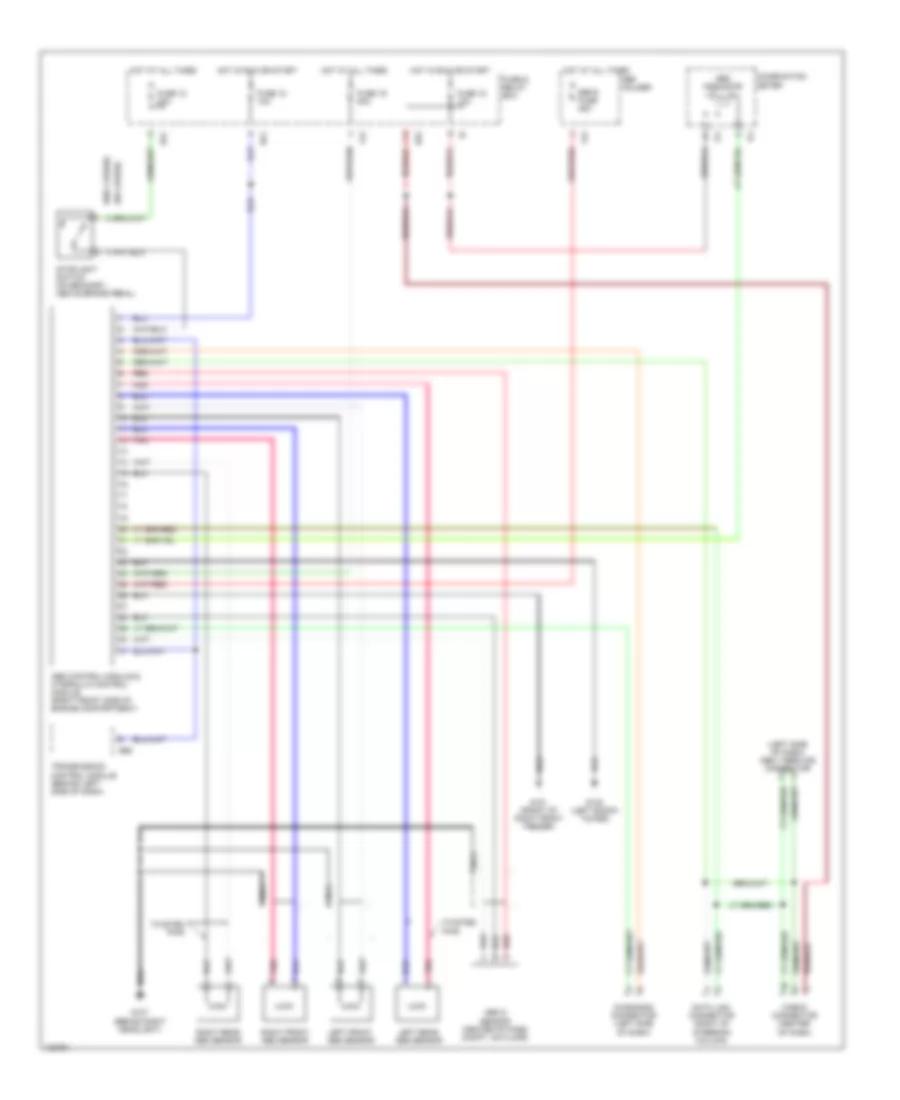
List of elements for Anti-lock Brake Wiring Diagrams for Subaru Legacy GT 1999:
- (left side of dash) obd ii service connector
- (w/o cruise)
- Abs control module & hydraulic control module (right front side of engine compartment)
- Abs g sensor (center of pass compt, on floor)
- Abs indicator
- B51
- B52
- B56
- Check connector (center of dash)
- Combination meter
- Data link connector (right of steering column)
- Diagnosis connector (left side of dash)
- F34
- F42
- Fuse & relay box
- Fuse 12 20a
- Fuse 15 10a
- Fuse 18 10a
- Fuse 19 20a
- G101 (front of right front fender)
- G102 (left shock tower)
- G107 (behind right headlight)
- Hot at all times
- Hot in run or start
- I14
- Left front abs sensor
- Left rear abs sensor
- Nca
- Pnk
- Red
- Right front abs sensor
- Right rear abs sensor
- Sbf holder
- Sbf-6 fuse 45a
- Stoplight switch (on bracket, above brake pedal)
- Transmission control module (behind left side of dash)
- Twisted pair
 Čeština
 Dansk
Dansk Deutsch
 Ελληνικά
 English
 English
 Español
 Suomi
Suomi Français
 Français
 Hrvatski
 Magyar
 Italiano
 日本語
日本語 한국어
한국어 Nederlands
 Polski
 Português
 Português
 Română
 Русский
 Slovenčina
 Slovenščina
 Svenska
 Türkçe
 中文 (中国)
 עברית
עברית
