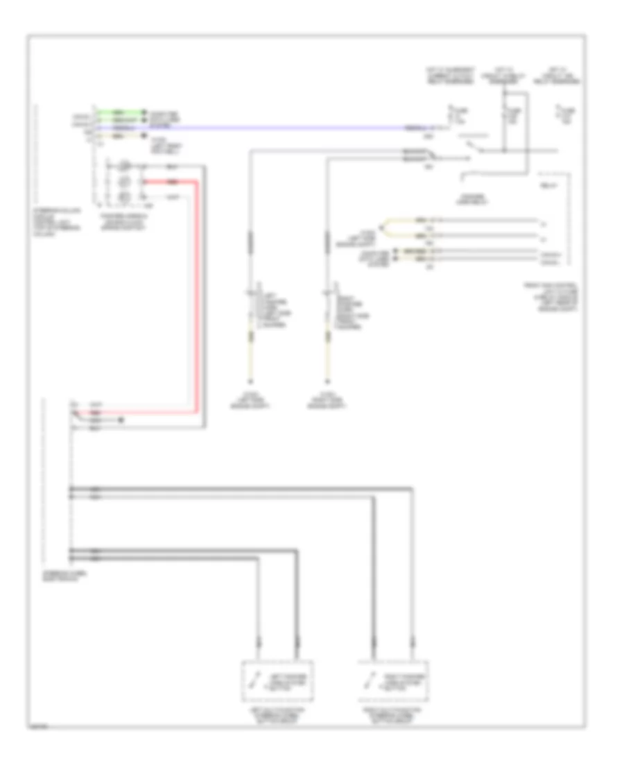
HORN
Horn Wiring Diagram for Mercedes-Benz GLK350 4Matic 2010
 https://portal-diagnostov.com/license.html
Automotive Electricians Portal FZCO
Automotive Electricians Portal FZCO
https://portal-diagnostov.com/license.html
https://portal-diagnostov.com/license.html
Automotive Electricians Portal FZCO
Automotive Electricians Portal FZCO
List of elements for Horn Wiring Diagram for Mercedes-Benz GLK350 4Matic 2010:
- 14m
- 15m
- 22i
- 30z
- A45
- C5c
- Can b h
- Can b l
- Can e h
- Can e l
- Computer data lines system
- Fanfare horn relay
- Fanfare horns & air bag clock spring contact
- Front sam control unit w/ fuse & relay module (left rear of engine compt)
- Fuse 31a 15a
- Fuse 31b 15a
- Fuse 7.5a
- Hot w/ circuit 15 relay energized
- Hot w/ circuit 15r relay energized
- Hot w/ quiescent current cutout relay energized
- Left fanfare horn (left side front bumper)
- Left fanfare horn system button
- Left multi-function steering wheel button group
- Nca
- Red
- Relay
- Right fanfare horn (right side front bumper)
- Right fanfare horn system button
- Right multi-function steering wheel button group
- Steering column module control unit (top of steering column)
- Steering wheel electronics
- W15/5 (left front footwell)
- W16/3 (left side engine compt)
- W16/4 (right side engine compt)
 Čeština
 Dansk
Dansk Deutsch
 Ελληνικά
 English
 English
 Español
 Suomi
Suomi Français
 Français
 Hrvatski
 Magyar
 Italiano
 日本語
日本語 한국어
한국어 Nederlands
 Polski
 Português
 Português
 Română
 Русский
 Slovenčina
 Slovenščina
 Svenska
 Türkçe
 中文 (中国)
 עברית
עברית
