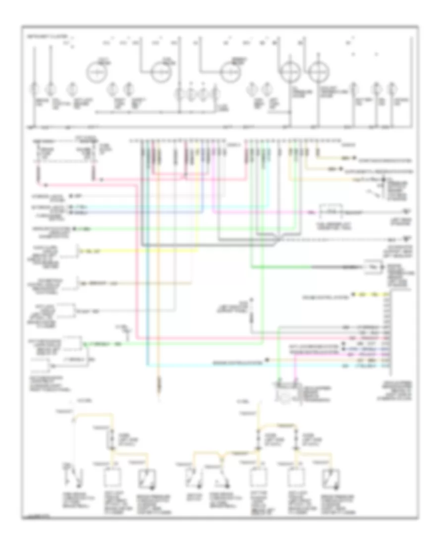
INSTRUMENT CLUSTER
Instrument Cluster Wiring Diagram, Analog for Chevrolet Astro 1995
 https://portal-diagnostov.com/license.html
Automotive Electricians Portal FZCO
Automotive Electricians Portal FZCO
https://portal-diagnostov.com/license.html
https://portal-diagnostov.com/license.html
Automotive Electricians Portal FZCO
Automotive Electricians Portal FZCO
List of elements for Instrument Cluster Wiring Diagram, Analog for Chevrolet Astro 1995:
- (behind left
- (behind left side of i/p)
- (behind right
- (headlight
- (in engine compt front plenum panel)
- (left front of cowl, on
- (left rear of engine)
- (on radiator support, near left headlamp)
- (turn-hazard
- 1995 vftc c
- A11
- A12
- A13
- A14
- A15
- A16
- A17
- A18
- Air bag ind.
- Anti-lock
- Anti-lock brakes ind.
- Anti-lock brakes system
- Anti-lock module (left front of cowl, on brake master cylinder)
- Audio alarm
- B10
- B11
- B12
- B14
- Battery ind.
- Brake fuse 15a
- Brake ind.
- Brake master
- Brake pressure warning switch (in engine compt, near master cylinder)
- C10
- C11
- C12
- C13
- C14
- Center)
- Conn a
- Conn b
- Control module
- Convenience
- Coolant temperature gauge
- Cruise control system
- Cylinder)
- Daytime
- Daytime running
- Daytime running lamps relay
- Dimmer switch)
- Diode (left side of cowl)
- Drl ind.
- Engine controls system
- Engine coolant temperature sensor (left side of engine)
- Exterior lights
- Fuel gauge
- Fuel sender unit (inside fuel tank)
- Fuse block: i/p
- G108
- G108 (left radiator support panel)
- G114
- Gauges fuse 20a
- Headlights system
- High beam ind.
- Hot in run
- Ignition switch
- Illum. lamps
- Instrument cluster
- Interior lights
- Kick panel)
- Lamps module
- Left turn ind.
- Mal- function ind.
- Module
- Oil pressure gauge
- Oil pressure switch & sender (top rear of engine)
- Only
- Or start
- Park brake warning switch (at park brake pedal)
- Powertrain
- Right turn ind.
- Running lamps module (behind left side of i/p)
- Safety belt ind.
- Side of i/p, in
- Speedo- meter
- Starting/charging system
- Switch)
- System
- Tan
- Vehicle speed sensor (rear of transmission)
- Vehicle speed sensor buffer (behind i/p, right side of steering column)
- Volt- meter
- W/ drl
- W/o drl
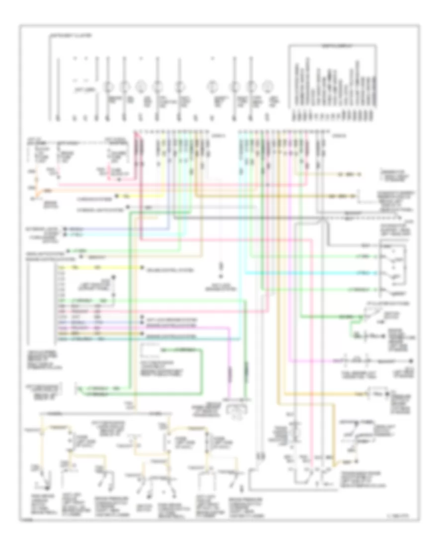
Instrument Cluster Wiring Diagram, Digital for Chevrolet Astro 1995
 https://portal-diagnostov.com/license.html
Automotive Electricians Portal FZCO
Automotive Electricians Portal FZCO
https://portal-diagnostov.com/license.html
https://portal-diagnostov.com/license.html
Automotive Electricians Portal FZCO
Automotive Electricians Portal FZCOList of elements for Instrument Cluster Wiring Diagram, Digital for Chevrolet Astro 1995:
- (at rear of
- (behind left side of i/p)
- (behind left side of i/p,
- (engine compartment front plenum panel)
- (not used)
- (on radiator support, near left headlamp)
- (right front
- (top rear of engine)
- (turn-hazard
- 1995 vftc c
- A10
- A11
- A12
- A13
- A14
- Air bag ind.
- Anti- lock ind.
- Anti-lock brakes system
- Anti-lock module (left front of cowl, on brake master cylinder)
- B10
- B11
- B12
- B13
- B15
- B16
- Battery
- Battery telltale
- Brake fuse 15a
- Brake ind.
- Brake pressure warning switch (in engine compt, near master cylinder)
- Brake switch
- C10
- C11
- C12
- C13
- C14
- Conn a
- Conn b
- Coolant temperature
- Cruise control system
- Daytime running
- Daytime running lamps relay
- Diagnostic energy
- Digital display
- Diode (left side of cowl)
- Drl ind.
- E/m
- Eng/metric switch
- Engine controls system
- Engine coolant temperature sensor (left side of engine)
- Exterior lights
- Fuel level
- Fuel sender unit (inside fuel tank)
- Fuse block:i/p
- G108
- G108 (left radiator support panel)
- G114 (left rear of engine)
- Gauges fuse 20a
- Generator
- Gnd
- Head
- Headlight switch assembly
- Headlights system
- High beam ind.
- Hot at all times
- Hot in run
- I/p cluster switches
- Ignition 3 (run)
- Ignition switch
- Instrument cluster
- Interior lights system
- Lamps module
- Left turn ind.
- Mal- function ind.
- Near kick panel)
- Of engine)
- Off
- Oil pressure
- Oil pressure switch & sender
- Or start
- Panel lamp dimmer
- Park
- Park brake warning switch (at park brake pedal)
- Park lamp switch
- Pnk/
- Power ground
- Reserve module
- Reset
- Right turn ind.
- Safety belt ind.
- Signal ground
- Speed sensor
- Stop/ hz fuse 20a
- Switch)
- System
- Tan
- Tan/
- Trans- mission range indicator lamp b
- Transmission range indicator relay (left side of i/p, near steering column)
- Transmission)
- Trip
- Trip reset switch
- Trip/season odo switch
- Vehicle
- Vehicle speed sensor buffer (behind i/p, right side of steering column)
- Vehicle speed signal
- W/ drl
- W/o drl
- Warning systems

 Čeština
 Dansk
Dansk Deutsch
 Ελληνικά
 English
 English
 Español
 Suomi
Suomi Français
 Français
 Hrvatski
 Magyar
 Italiano
 日本語
日本語 한국어
한국어 Nederlands
 Polski
 Português
 Português
 Română
 Русский
 Slovenčina
 Slovenščina
 Svenska
 Türkçe
 中文 (中国)
