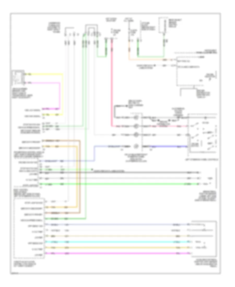
AIR CONDITIONING
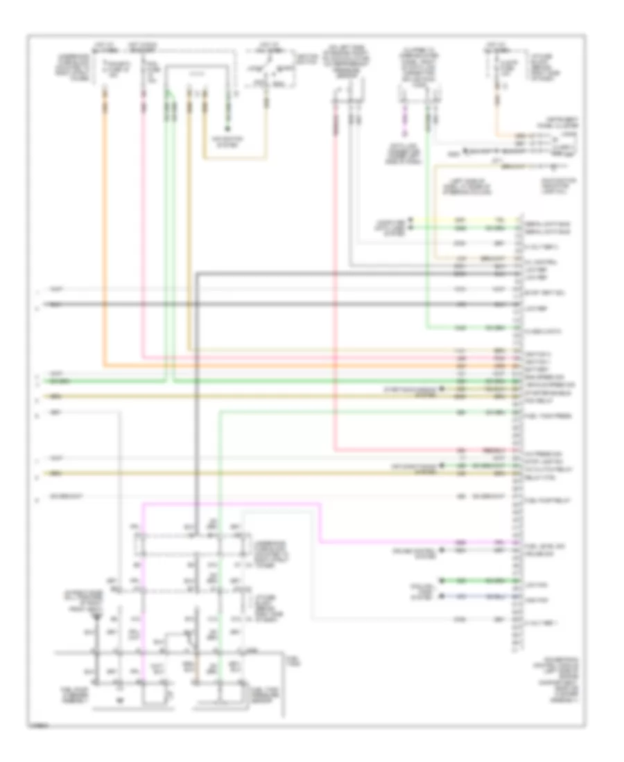
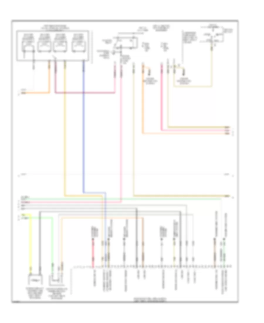
3.6L VIN 7
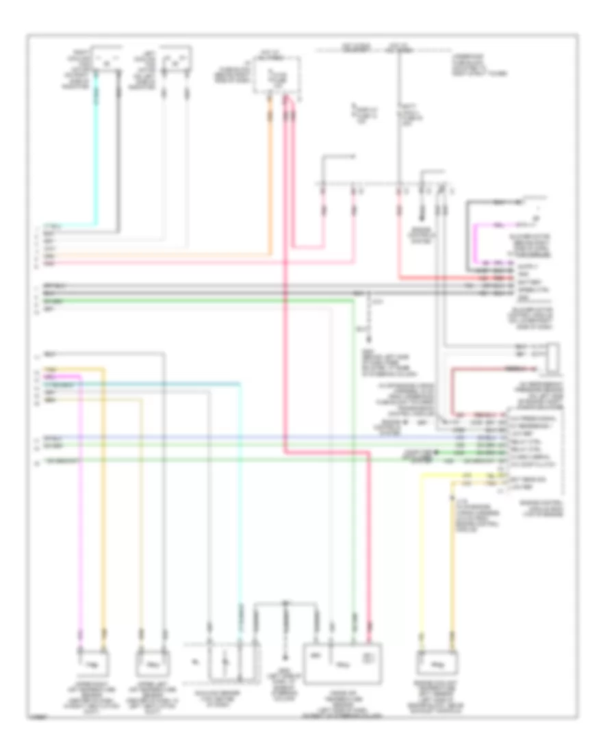
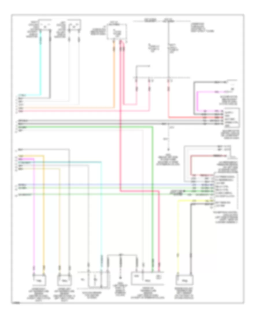
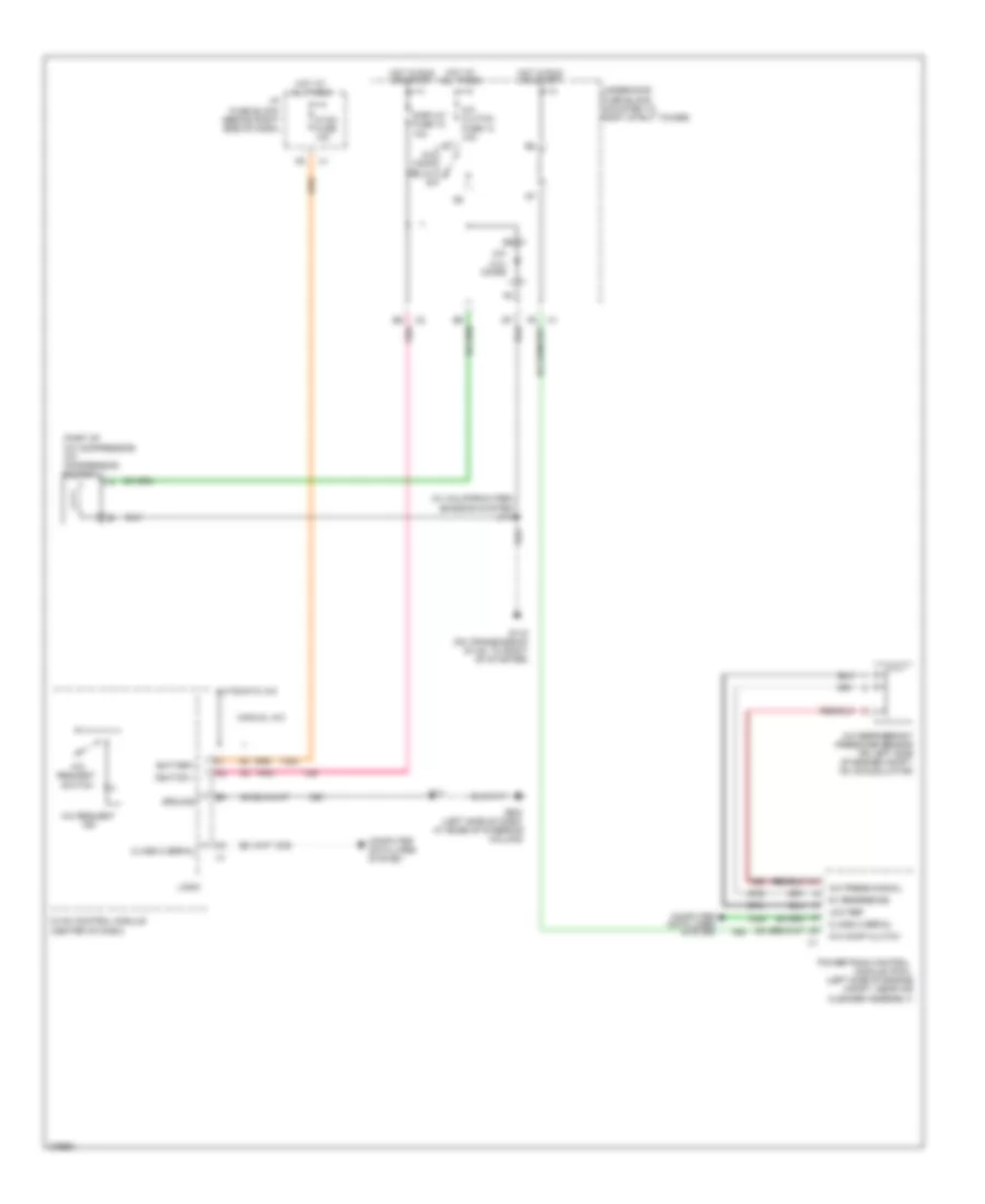
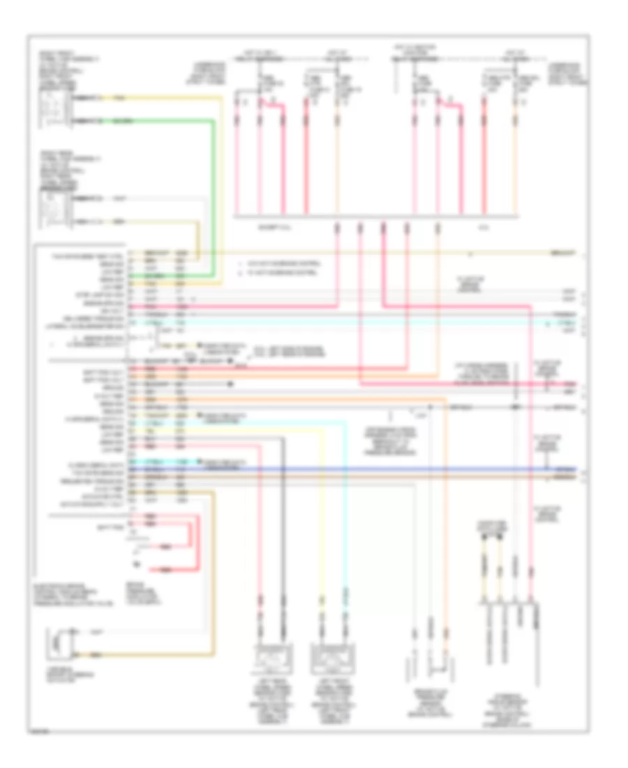
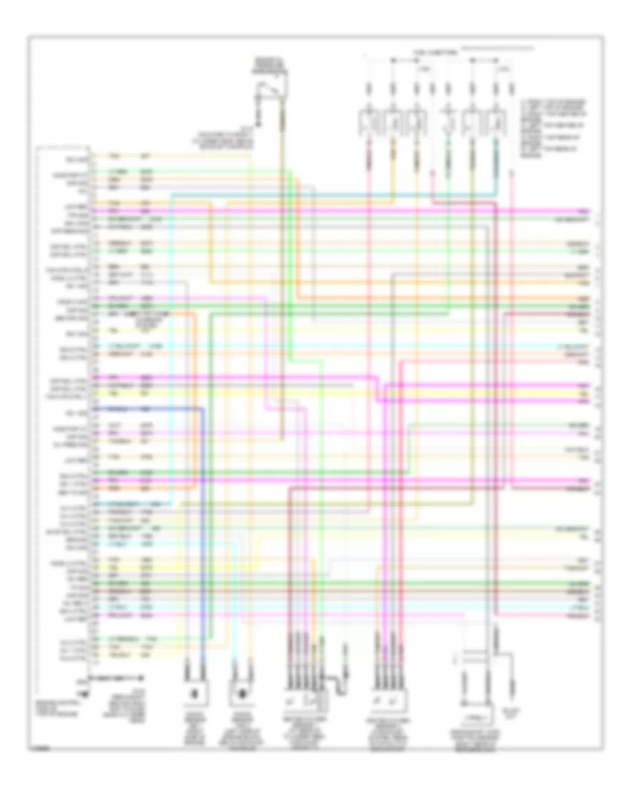
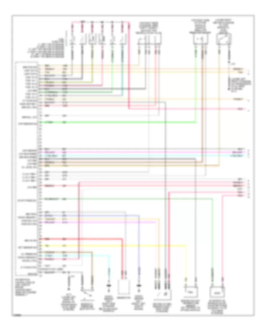
3.6L VIN 7, Automatic A/C Wiring Diagram (1 of 2) for Buick Allure Super 2008
 https://portal-diagnostov.com/license.html
Automotive Electricians Portal FZCO
Automotive Electricians Portal FZCO
https://portal-diagnostov.com/license.html
https://portal-diagnostov.com/license.html
Automotive Electricians Portal FZCO
Automotive Electricians Portal FZCO
List of elements for 3.6L VIN 7, Automatic A/C Wiring Diagram (1 of 2) for Buick Allure Super 2008:
- (in back of right headlamp on frame) g100
- (mounted to bank 1 cylinder head above exhaust manifold) g115
- (part of a/c compressor) a/c compressor clutch
- A/c clu diode
- A/c clutch fuse 13 10a
- A/c comp relay
- A/c request ind
- A/c request switch
- A10
- A11
- A12
- A18
- A19
- Air temp a
- Air temp b
- Auto
- B10
- B11
- B12
- Battery
- Blower motor sw
- C18
- C19
- Class 2 serial
- Computer data lines system
- Defogger
- E10
- Fan 1 fuse 29 30a
- Fan 1 relay
- Fan 2 fuse 32 30a
- Fan 2 relay
- Fan 3 relay
- G202 (left side of dash, at base of steering column)
- Ground
- High
- Hot at all times
- Hot in run or start
- Hvac control module (center of dash)
- Ign 1 volt
- Illum
- Ind
- Interior lights system
- J116
- J211
- K14
- K15
- K18
- K19
- L14
- Left air temperature actuator (left side of dash, on hvac module)
- Logic
- Low
- Low ref
- Lower left air temperature sensor (behind hvac control module)
- Lower right air temperature sensor (behind hvac control module)
- M14
- M15
- M18
- M19
- Mode actuator (lower left side of hvac assembly)
- Mode door a
- Mode switch
- Off
- Pnk
- Position sig
- Rear defogger switch
- Recirc a
- Recirc b
- Recirculation
- Recirculation actuator (near right "a" pillar, on upper hvac case)
- Recirculation switch
- Right air temperature actuator (right side of hvac module)
- Sensor sig
- Speed ctrl
- Tan
- Temperature control sw
- Underhood fuse block (mounted to right strut tower)
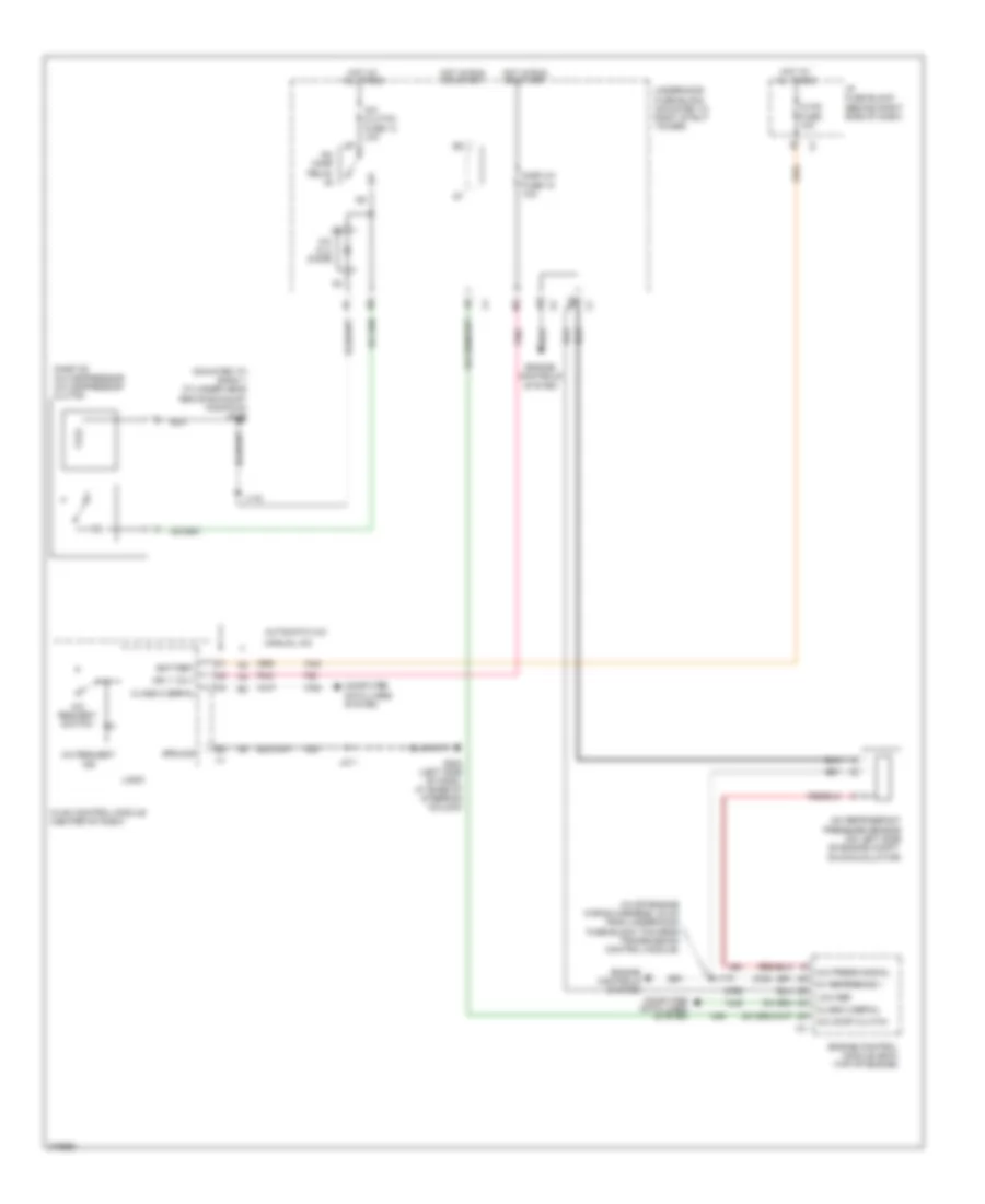
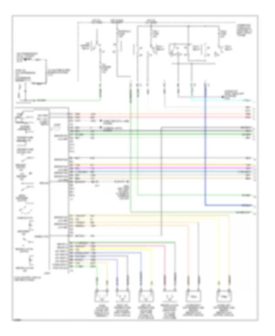
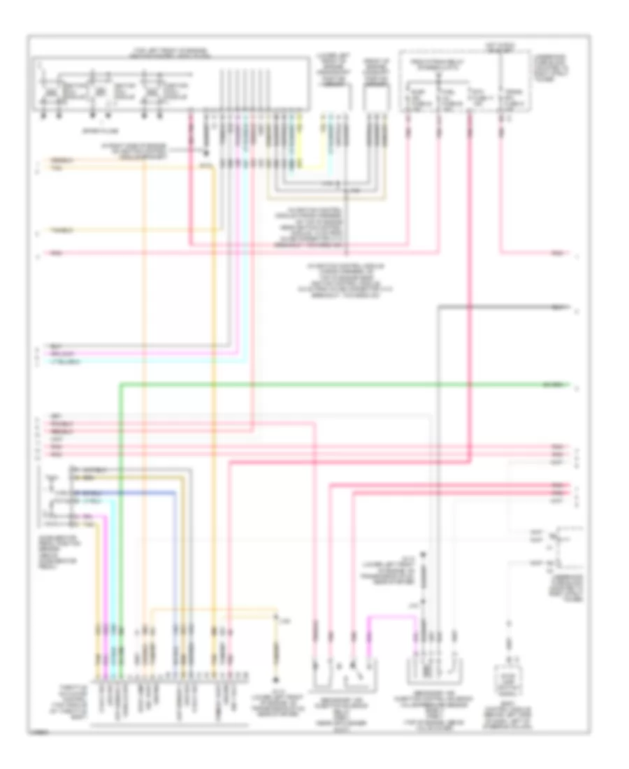
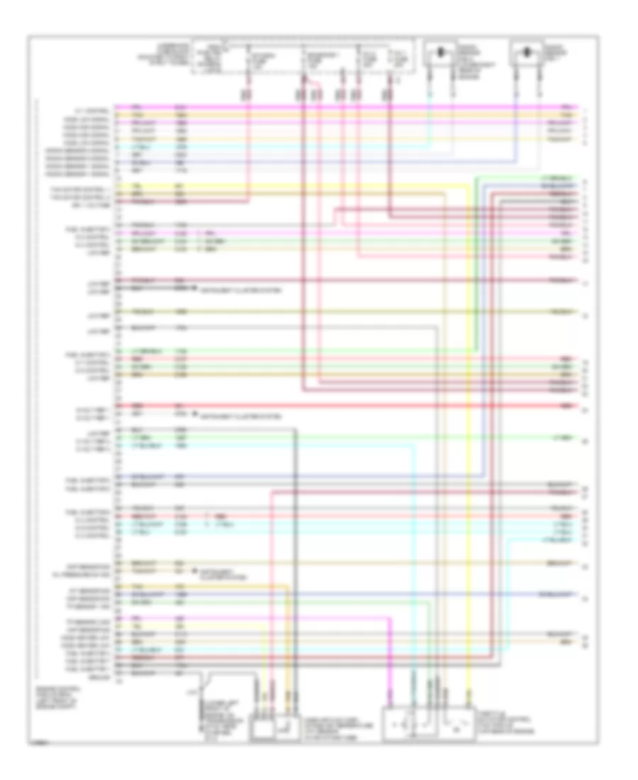
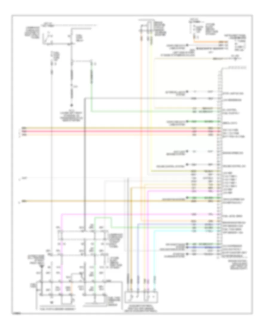
3.6L VIN 7, Automatic A/C Wiring Diagram (2 of 2) for Buick Allure Super 2008
 https://portal-diagnostov.com/license.html
Automotive Electricians Portal FZCO
Automotive Electricians Portal FZCO
https://portal-diagnostov.com/license.html
https://portal-diagnostov.com/license.html
Automotive Electricians Portal FZCO
Automotive Electricians Portal FZCOList of elements for 3.6L VIN 7, Automatic A/C Wiring Diagram (2 of 2) for Buick Allure Super 2008:
- (in off-engine wiring harness, 32 cm from underhood fuse block towards transmission control module)
- 5v reference 1
- A/c comp clutch
- A/c press signal
- A/c refrigerant pressure sensor (on left side of engine compt, on accumulator)
- Batt main 4 fuse 30 30a
- Battery
- Blower motor (behind right side of dash, in hvac module)
- Blower motor control module (on lower right side of dash)
- Class 2 serial
- Computer data lines system
- D11
- Display fuse 18 10a
- Ect sens sig
- Engine control module (ecm) (top of engine)
- Engine controls system
- Engine coolant temperature (ect) sensor (left side of engine block, above exhaust manifold)
- G200 (behind left side of dash knee bolster, at base of steering column)
- G202 (left side of dash, at base of steering column)
- Gnd
- Hot at all times
- Hot in run or start
- Hvac fuse 10a
- I/p fuse block (behind right side of dash)
- Ign 1 volt
- Inside air temperature sensor (left side of dash, on right of steering column)
- J118
- J119 (in on-engine wiring harness, 34.5 cm from engine control module)
- J211
- J213
- Left cooling fan motor (on left side of radiator)
- Low ref
- Pnk
- Red
- Relay ctrl
- Right cooling fan motor (on right b
- Speed ctrl
- Sunload sensor (top center of dash)
- Tan
- Underhood fuse block (mounted to right strut tower)
- Upper left air temperature sensor (center of dash, in left ventilation duct)
- Upper right air temperature sensor (center of dash, in right ventilation duct)
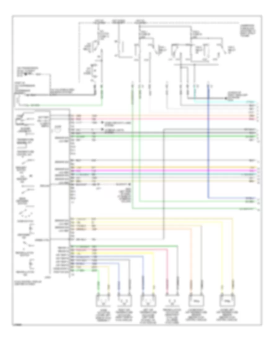
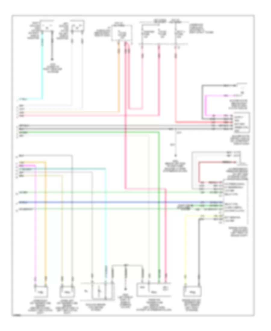
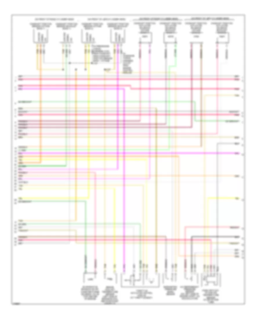
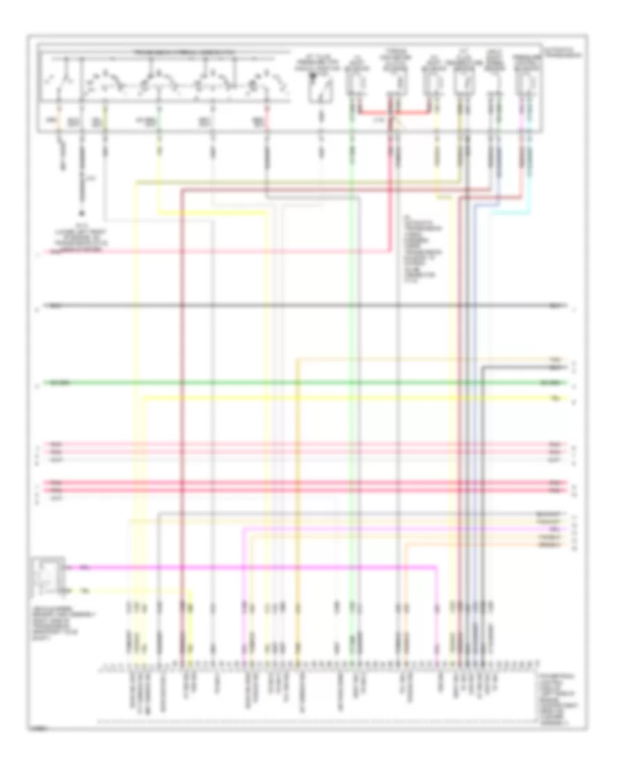
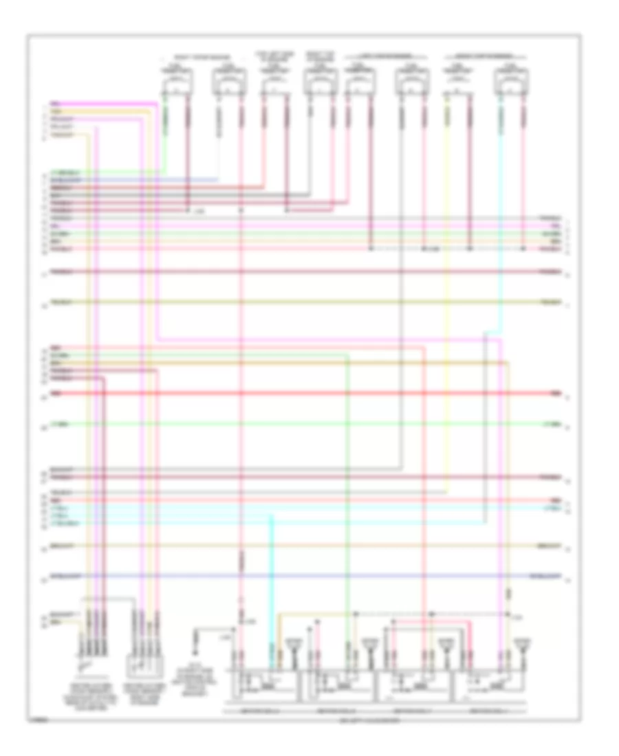
3.6L VIN 7, Compressor Wiring Diagram for Buick Allure Super 2008
 https://portal-diagnostov.com/license.html
Automotive Electricians Portal FZCO
Automotive Electricians Portal FZCO
https://portal-diagnostov.com/license.html
https://portal-diagnostov.com/license.html
Automotive Electricians Portal FZCO
Automotive Electricians Portal FZCOList of elements for 3.6L VIN 7, Compressor Wiring Diagram for Buick Allure Super 2008:
- (in off-engine wiring harness, 32 cm from underhood fuse block towards transmission control module)
- (mounted to bank 1 cylinder head above exhaust manifold) g115
- (part of a/c compressor) a/c compressor clutch
- 5v reference 1
- A/c clu diode
- A/c clutch fuse 13 10a
- A/c comp clutch
- A/c comp relay
- A/c press signal
- A/c refrigerant pressure sensor (on left side of engine compt, on accumulator)
- A/c request ind
- A/c request switch
- Automatic a/c
- Battery
- Class 2 serial
- Computer data lines system
- Display fuse 18 10a
- Engine control module (ecm) (top of engine)
- Engine controls system
- G202 (left side of dash, at base of steering column)
- Ground
- Hot at all times
- Hot in run or start
- Hvac control module (center of dash)
- Hvac fuse 10a
- I/p fuse block (behind right side of dash)
- Ign 1 volt
- J116
- J118
- J211
- Logic
- Low ref
- Manual a/c
- Pnk
- Underhood fuse block (mounted to right strut tower)
3.8L VIN 2
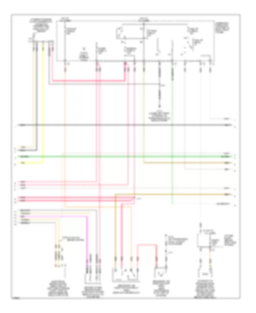
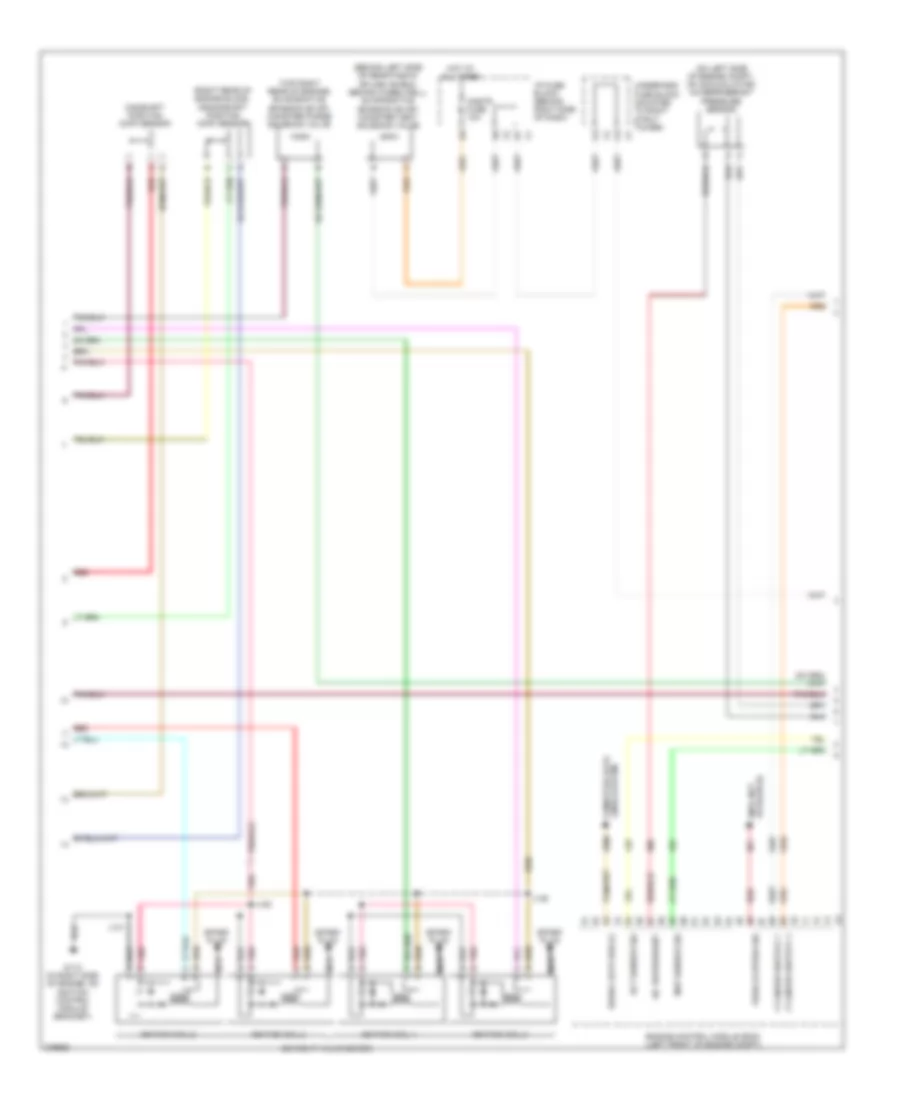
3.8L VIN 2, Automatic A/C Wiring Diagram (1 of 2) for Buick Allure Super 2008
 https://portal-diagnostov.com/license.html
Automotive Electricians Portal FZCO
Automotive Electricians Portal FZCO
https://portal-diagnostov.com/license.html
https://portal-diagnostov.com/license.html
Automotive Electricians Portal FZCO
Automotive Electricians Portal FZCOList of elements for 3.8L VIN 2, Automatic A/C Wiring Diagram (1 of 2) for Buick Allure Super 2008:
- (in back of right headlamp on frame) g100
- (on transmission stud, to right of starter) g115
- (part of a/c compressor) a/c compressor clutch
- (w/ california pzev emission system) j114
- A/c clu diode
- A/c clutch fuse 13 10a
- A/c comp relay
- A/c request ind
- A10
- A11
- A12
- A18
- A19
- Air temp a
- Air temp b
- Auto
- B10
- B11
- B12
- Battery
- Blower motor sw
- C18
- C19
- Class 2 serial
- Computer data lines system
- Defogger
- E10
- Fan 1 fuse 29 30a
- Fan 1 relay
- Fan 2 fuse 32 30a
- Fan 2 relay
- Fan 3 relay
- G202 (left side of dash, at base of steering column)
- Ground
- High
- Hot at all times
- Hot in run or start
- Hvac control module (center of dash)
- Ign 1 volt
- Illum
- Ind
- Interior lights system
- J211
- K14
- K15
- K18
- K19
- L14
- Left air temperature actuator (left side of dash, on hvac module)
- Logic
- Low
- Low ref
- Lower left air temperature sensor (behind hvac control module)
- Lower right air temperature sensor (behind hvac control module)
- M14
- M15
- M18
- M19
- Mode actuator (lower left side of hvac assembly)
- Mode door a
- Mode switch
- Off
- Pnk
- Position sig
- Rear defogger switch
- Recirc a
- Recirc b
- Recirculation
- Recirculation actuator (near right "a" pillar, on upper hvac case)
- Recirculation switch
- Request switch a/c
- Right air temperature actuator (right side of hvac module)
- Sensor sig
- Speed ctrl
- Tan
- Temperature control sw
- Underhood fuse block (mounted to right strut tower)
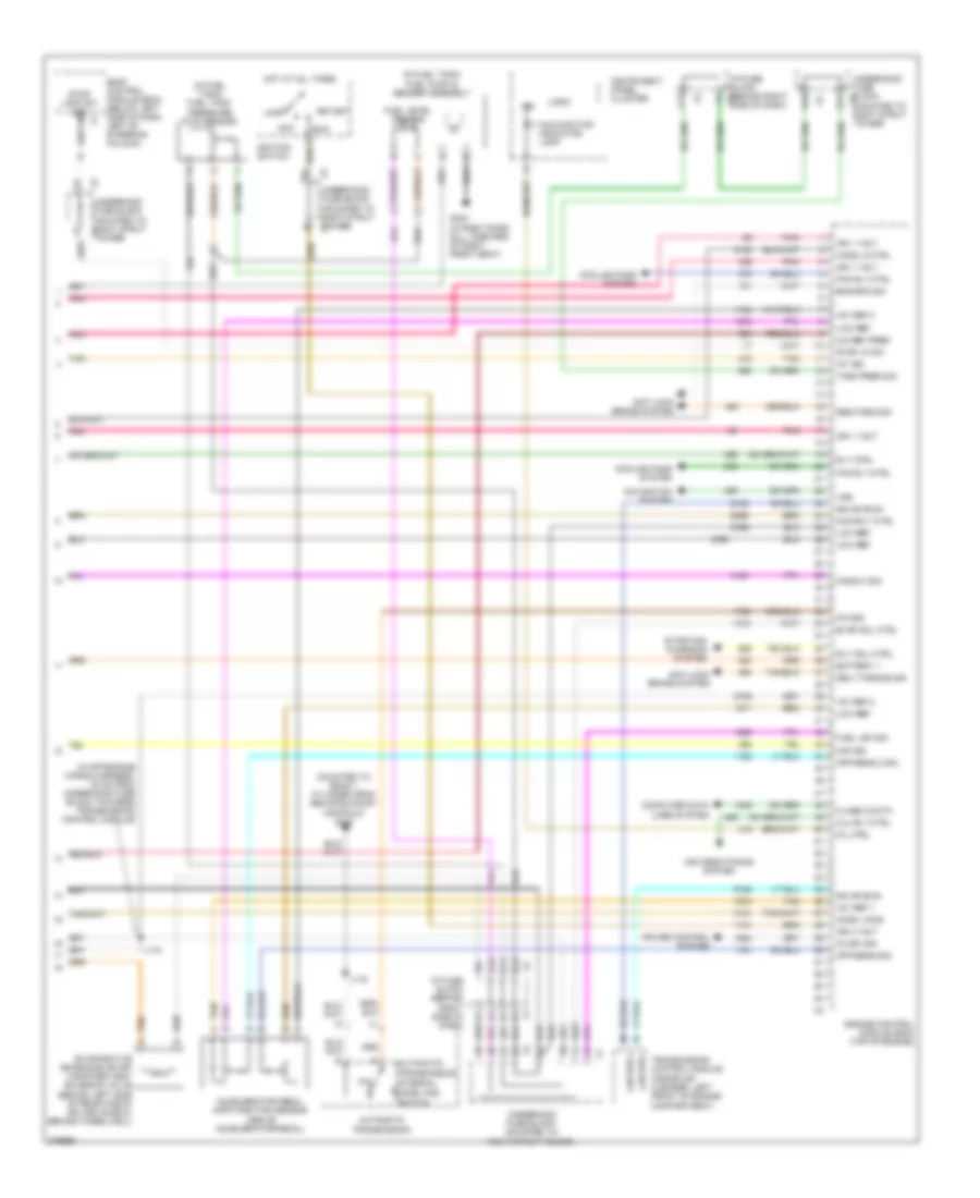
3.8L VIN 2, Automatic A/C Wiring Diagram (2 of 2) for Buick Allure Super 2008
 https://portal-diagnostov.com/license.html
Automotive Electricians Portal FZCO
Automotive Electricians Portal FZCO
https://portal-diagnostov.com/license.html
https://portal-diagnostov.com/license.html
Automotive Electricians Portal FZCO
Automotive Electricians Portal FZCOList of elements for 3.8L VIN 2, Automatic A/C Wiring Diagram (2 of 2) for Buick Allure Super 2008:
- 5v reference 2
- A/c comp clutch
- A/c press signal
- A/c refrigerant pressure sensor (on left side of engine compt, on accumulator)
- Batt main 4 fuse 30 30a
- Battery
- Blower motor (behind right side of dash, in hvac module)
- Blower motor control module (on lower right side of dash)
- Class 2 serial
- Computer data lines system
- D11
- Display fuse 18 10a
- Ect sens sig
- Engine coolant temperature (ect) sensor (on top right of intake manifold)
- G200 (behind left side of dash knee bolster, at base of steering column)
- G202 (left side of dash, at base of steering column)
- Gnd
- Hot at all times
- Hot in run or start
- Hvac fuse 10a
- I/p fuse block (behind right side of dash)
- Ign 1 volt
- Inside air temperature sensor (left side of dash, on right of steering column)
- J211
- J213
- Left cooling fan motor (on left side of radiator)
- Low ref
- Pnk
- Powertrain control module (pcm) (left side of engine compt, near air cleaner assembly)
- Red
- Relay ctrl
- Right cooling fan motor (on right b
- Speed ctrl
- Sunload sensor (top center of dash)
- Tan
- Underhood fuse block (mounted to right strut tower)
- Upper left air temperature sensor (center of dash, in left ventilation duct)
- Upper right air temperature sensor (center of dash, in right ventilation duct)
3.8L VIN 2, Compressor Wiring Diagram for Buick Allure Super 2008
 https://portal-diagnostov.com/license.html
Automotive Electricians Portal FZCO
Automotive Electricians Portal FZCO
https://portal-diagnostov.com/license.html
https://portal-diagnostov.com/license.html
Automotive Electricians Portal FZCO
Automotive Electricians Portal FZCOList of elements for 3.8L VIN 2, Compressor Wiring Diagram for Buick Allure Super 2008:
- (left side of engine compt, near air cleaner assembly)
- (part of a/c compressor) a/c compressor clutch
- (w/ california pzev emission system) j114
- 5v reference
- A/c clu diode
- A/c clutch fuse 13 10a
- A/c comp clutch
- A/c comp relay
- A/c press signal
- A/c refrigerant pressure sensor (on left side of engine compt, on accumulator)
- A/c request ind
- A/c request switch
- Automatic a/c
- Battery
- Class 2 serial
- Computer data lines system
- Display fuse 18 10a
- G115 (on transmission stud, to right of starter)
- G202 (left side of dash, at base of steering column)
- Ground
- Hot at all times
- Hot in run or start
- Hvac control module (center of dash)
- Hvac fuse 10a
- I/p fuse block (behind right side of dash)
- Ignition 1
- J211
- Logic
- Low ref
- Manual a/c
- Pnk
- Powertrain control module (pcm)
- Underhood fuse block (mounted to right strut tower)
5.3L VIN C
5.3L VIN C, Automatic A/C Wiring Diagram (1 of 2) for Buick Allure Super 2008
 https://portal-diagnostov.com/license.html
Automotive Electricians Portal FZCO
Automotive Electricians Portal FZCO
https://portal-diagnostov.com/license.html
https://portal-diagnostov.com/license.html
Automotive Electricians Portal FZCO
Automotive Electricians Portal FZCOList of elements for 5.3L VIN C, Automatic A/C Wiring Diagram (1 of 2) for Buick Allure Super 2008:
- (in back of right headlamp on frame) g100
- (on transmission stud, to right of starter) g115
- (part of a/c compressor) a/c compressor clutch
- (w/ california pzev emission system) j114
- 87a
- A/c cmprsr fuse 10a
- A/c cmprsr relay
- A/c request ind
- A10
- A11
- A12
- Air temp a
- Air temp b
- Auto
- B10
- B11
- B12
- Battery
- Blower motor sw
- Class 2 serial
- Computer data lines system
- Defogger
- Emission 2 fuse 15a
- Fan 1 fuse 30a
- Fan 1 relay
- Fan 2 fuse 30a
- Fan 2 relay
- Fan 3 relay
- G202 (left side of dash, at base of steering column)
- Ground
- High
- Hot at all times
- Hot in run or start
- Hvac control module (center of dash)
- Ign 1 volt
- Illum
- Ind
- Interior lights system
- J211
- Left air temperature actuator (left side of dash, on hvac module)
- Logic
- Low
- Low ref
- Lower left air temperature sensor (behind hvac control module)
- Lower right air temperature sensor (behind hvac control module)
- Mode actuator (lower left side of hvac assembly)
- Mode door a
- Mode switch
- Off
- Pnk
- Position sig
- Rear defogger switch
- Recirc a
- Recirc b
- Recirculation
- Recirculation actuator (near right "a" pillar, on upper hvac case)
- Recirculation switch
- Request switch a/c
- Right air temperature actuator (right side of hvac module)
- Sensor sig
- Speed ctrl
- Tan
- Temperature control sw
- Underhood fuse block (mounted to right strut tower)
5.3L VIN C, Automatic A/C Wiring Diagram (2 of 2) for Buick Allure Super 2008
 https://portal-diagnostov.com/license.html
Automotive Electricians Portal FZCO
Automotive Electricians Portal FZCO
https://portal-diagnostov.com/license.html
https://portal-diagnostov.com/license.html
Automotive Electricians Portal FZCO
Automotive Electricians Portal FZCOList of elements for 5.3L VIN C, Automatic A/C Wiring Diagram (2 of 2) for Buick Allure Super 2008:
- 5v reference 2
- A/c comp clutch
- A/c press signal
- A/c refrigerant pressure sensor (on left side of engine compt, on accumulator)
- Batt 4 fuse 30a
- Battery
- Blower motor (behind right side of dash, in hvac module)
- Blower motor control module (on lower right side of dash)
- Class 2 serial
- Compass fuse 10a
- Computer data lines system
- D11
- Ect sens sig
- Engine control module (ecm) (left front of engine compt)
- Engine coolant temperature (ect) sensor (left front of engine)
- G100 (in back of right headlamp on frame)
- G200 (behind left side of dash knee bolster, at base of steering column)
- G202 (left side of dash, at base of steering column)
- Gnd
- Hot at all times
- Hot in run or start
- Hvac fuse 10a
- I/p fuse block (behind right side of dash)
- Ign 1 volt
- Inside air temperature sensor (left side of dash, on right of steering column)
- J211
- J213
- Left cooling fan motor (on left side of radiator)
- Low ref
- Pnk
- Red
- Relay ctrl
- Right cooling fan motor (on right b
- Speed ctrl
- Sunload sensor (top center of dash)
- Tan
- Underhood fuse block (mounted to right strut tower)
- Upper left air temperature sensor (center of dash, in left ventilation duct)
- Upper right air temperature sensor (center of dash, in right ventilation duct)
5.3L VIN C, Compressor Wiring Diagram for Buick Allure Super 2008
 https://portal-diagnostov.com/license.html
Automotive Electricians Portal FZCO
Automotive Electricians Portal FZCO
https://portal-diagnostov.com/license.html
https://portal-diagnostov.com/license.html
Automotive Electricians Portal FZCO
Automotive Electricians Portal FZCOList of elements for 5.3L VIN C, Compressor Wiring Diagram for Buick Allure Super 2008:
- (or 239)
- (part of a/c compressor) a/c compressor clutch
- 5v reference
- A/c cmprsr fuse 10a
- A/c cmprsr relay
- A/c comp clutch
- A/c press signal
- A/c refrigerant pressure sensor (on left side of engine compt, on accumulator)
- A/c request ind
- A/c request switch
- Automatic a/c
- Battery
- Class 2 serial
- Computer data lines system
- Emission 2 fuse 15a
- Engine control module (ecm) (left front of engine compt)
- G115 (on transmission stud, to right of starter)
- G202 (left side of dash, at base of steering column)
- Ground
- Hot at all times
- Hot in run or start
- Hvac control module (center of dash)
- Hvac fuse 10a
- I/p fuse block (behind right side of dash)
- Ignition 1
- J114 (w/ california pzev emission system)
- J211
- Logic
- Low ref
- Manual a/c
- Pnk
- Underhood fuse block (mounted to right strut tower)
ANTI-LOCK BRAKES
Anti-lock Brakes Wiring Diagram (1 of 2) for Buick Allure Super 2008
 https://portal-diagnostov.com/license.html
Automotive Electricians Portal FZCO
Automotive Electricians Portal FZCO
https://portal-diagnostov.com/license.html
https://portal-diagnostov.com/license.html
Automotive Electricians Portal FZCO
Automotive Electricians Portal FZCOList of elements for Anti-lock Brakes Wiring Diagram (1 of 2) for Buick Allure Super 2008:
- (5.3l) j125
- (5.3l: left side of engine) (3.8l: left rear of engine)
- (i/p wiring harness, 14 cm from pass- through to brake fluid level switch)
- (off-engine wiring harness, 6 cm from breakout to brake fluid pressure sensor)
- (right front wheel hub assembly) (w/ active brake control) right front wheel speed sensor (wss)
- (right rear wheel hub assembly) (w/ active brake control) right rear wheel speed sensor (wss)
- 5-volt ref
- 5.3l
- A11
- Abs fuse 10a
- Abs fuse 23 10a
- Abs mtr fuse 31 40a
- Abs mtr fuse 40a
- Abs sol fuse 19 25a
- Abs sol fuse 25a
- Actuator ctrl
- Batt pos
- Batt pos volt
- Brake fluid pressure sensor (w/ active brake control)
- Brake pressure modulator valve (bpmv)
- Class 2 serial data
- Computer data lines system
- Delivered torque sig
- Electronic brake control module (ebcm) (integral to brake pressure modulator valve)
- Engine spd sig
- Engine spd sig hi spd serial data (-)
- Except 5.3l
- G115
- Ground
- Hi spd serial data (+)
- Hi spd serial data (-)
- Hot at all times
- Hot w/ ign 1 relay energized
- Hot w/ ignition main pcb relay energized
- Ign volt
- J107
- J216
- Lateral accelerometer sig
- Left front wheel speed sensor (wss) (w/ active brake control) (left front wheel hub assembly)
- Left rear wheel speed sensor (wss) (w/ active brake control) (left rear wheel hub assembly)
- Low ref
- Nca
- Pnk
- Red
- Requested torque sig
- Sens sig
- Steering angle sensor (w/ active brake control) (base of steering column)
- Stop lamp sw sig
- Tan
- Underhood fuse block (right front strut tower)
- Variable effort steering actuator
- W/ active brake control
- W/o active brake control
- Yaw rate sens sig
- Yaw rate sens test ctrl
Anti-lock Brakes Wiring Diagram (2 of 2) for Buick Allure Super 2008
 https://portal-diagnostov.com/license.html
Automotive Electricians Portal FZCO
Automotive Electricians Portal FZCO
https://portal-diagnostov.com/license.html
https://portal-diagnostov.com/license.html
Automotive Electricians Portal FZCO
Automotive Electricians Portal FZCOList of elements for Anti-lock Brakes Wiring Diagram (2 of 2) for Buick Allure Super 2008:
- 10-volt ref
- 3.8l
- 5-volt ref
- 5.3l
- Abs ind
- Batt pos volt
- Body control module (bcm) (left side of dash)
- Brake pedal position (bpp) sensor (left side of dash)
- Class 2 serial data
- Clstr fuse 10a
- Computer data lines system
- Delivered torque sig
- Driver information center (dic) display
- Driver information center (dic) switch
- Ecm class 2 serial data
- Engine control module (ecm) (left front of engine compt)
- Engine spd sig
- Except 3.8l
- Except 5.3l
- G202 (left side of dash)
- Ground
- Hot at all times
- I/p fuse block (right side of dash)
- Ign volt
- Instrument panel cluster (ipc)
- Ipc class 2 serial data
- J211
- Lateral accelerometer sig
- Logic
- Low ref
- Pcm class 2 serial data
- Pnk
- Powertrain control module (pcm)
- Requested torque sig
- Stop lp sw sig
- Traction control off ind
- Traction control switch
- Traction ctrl sw sig
- Underhood fuse block (right front strut tower)
- W/ active brake control
- W/o active brake control
- Yaw & lateral acceleration sensor (w/ active brake control) (center console)
- Yaw rate sen sig
- Yaw rate test cntrl
ANTI-THEFT
Forced Entry Wiring Diagram (1 of 2) for Buick Allure Super 2008
 https://portal-diagnostov.com/license.html
Automotive Electricians Portal FZCO
Automotive Electricians Portal FZCO
https://portal-diagnostov.com/license.html
https://portal-diagnostov.com/license.html
Automotive Electricians Portal FZCO
Automotive Electricians Portal FZCOList of elements for Forced Entry Wiring Diagram (1 of 2) for Buick Allure Super 2008:
- (center rear of roof) (if equipped) radio rear window antenna
- (front of driver's door sill) g301
- 3.8l
- 5.3l
- Ajar sw sig
- Antenna sig
- Batt volt (+)
- Bcm class 2
- Body control module (bcm) (left side of dash)
- C11
- C4 x2
- Class 2 ser data
- Coax
- Computer data lines system
- Door ajar indicator
- Dr ajar sw sig
- Dr open sw sig
- Driver door lock switch
- Driver information center (dic) display
- Front passenger door lock switch
- G101 (left front of engine compt)
- G202 (left side of dash)
- G301 (front of driver's door sill)
- G302 (front of front passenger's door sill)
- Ground
- Headlights system exterior lights system
- Hi beam relay
- Hood ajar switch (front of engine compt)
- Horn rly ctrl
- Horns system
- Hot at all times
- I/p fuse block (right side of dash)
- Ind ctrl
- Instrument panel cluster (ipc)
- Interior lights system
- J112
- J211
- J300
- J303
- J400 (w/ digital audio system)
- J501
- J605
- Lamp rly ctrl
- Lid ajar sw
- Lock
- Lock ctrl
- Lock sig
- Logic
- Nca
- Pnk
- Power distribution system
- Remote control door lock receiver (rcdlr) (right side of dash)
- Rfa ser data
- Rfa/mod fuse 10a
- Security indicator
- Security indicator lamp
- Sw sig
- Tan
- Trunk ajar indicator
- Trunk fuse 15a
- Underhood fuse block (right front strut tower)
- Unlock
- Unlock ctrl
- Unlock sig
- Volt (+)
- X3 c12
Forced Entry Wiring Diagram (2 of 2) for Buick Allure Super 2008
 https://portal-diagnostov.com/license.html
Automotive Electricians Portal FZCO
Automotive Electricians Portal FZCO
https://portal-diagnostov.com/license.html
https://portal-diagnostov.com/license.html
Automotive Electricians Portal FZCO
Automotive Electricians Portal FZCOList of elements for Forced Entry Wiring Diagram (2 of 2) for Buick Allure Super 2008:
- (body wiring harness, 26 cm from second breakout to g301) j315
- (body wiring harness, 29 cm from second breakout to inline connector x311)
- Ajar
- Door lock actuator
- Door lock ajar indicator switch
- Door lock cylinder switch
- Door lock open indicator switch
- Driver door lock (driver's door)
- Front passenger door lock (front passenger's door)
- G301 (front of driver's door sill)
- G302 (front of front passenger's door sill)
- J303
- J314
- J406
- J500
- J604
- Left rear door lock (left rear door)
- Lock
- Open
- Rear compartment lid latch (in trunk lid)
- Right rear door lock (right rear door)
- Tan
- Unlock
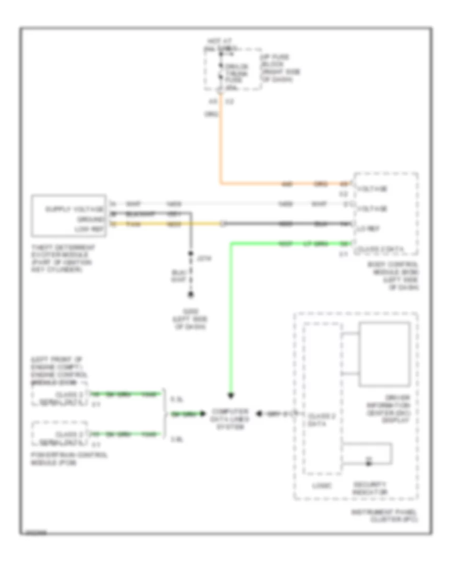
Pass-Key Wiring Diagram for Buick Allure Super 2008
 https://portal-diagnostov.com/license.html
Automotive Electricians Portal FZCO
Automotive Electricians Portal FZCO
https://portal-diagnostov.com/license.html
https://portal-diagnostov.com/license.html
Automotive Electricians Portal FZCO
Automotive Electricians Portal FZCOList of elements for Pass-Key Wiring Diagram for Buick Allure Super 2008:
- (left front of engine compt) engine control module (ecm)
- 3.8l
- 5.3l
- Body control module (bcm) (left side of dash)
- Class 2 data
- Class 2 serial data
- Computer data lines system
- Dr/lck trunk fuse 15a
- Driver information center (dic) display
- G202 (left side of dash)
- Ground
- Hot at all times
- I/p fuse block (right side of dash)
- Instrument panel cluster (ipc)
- J214
- Lo ref
- Logic
- Low ref
- Powertrain control module (pcm)
- Security indicator
- Tan
- Theft deterrent exciter module (part of ignition key cylinder)
- Voltage
BODY CONTROL MODULES
Body Control Modules Wiring Diagram for Buick Allure Super 2008
 https://portal-diagnostov.com/license.html
Automotive Electricians Portal FZCO
Automotive Electricians Portal FZCO
https://portal-diagnostov.com/license.html
https://portal-diagnostov.com/license.html
Automotive Electricians Portal FZCO
Automotive Electricians Portal FZCOList of elements for Body Control Modules Wiring Diagram for Buick Allure Super 2008:
- (left side of dash) body control module (bcm)
- (left side of dash) g200
- 10 volt ref
- 12 volt ref
- 5.3l
- A/t shft lk ctrl sol volt
- A/t shift lock ctrl
- A5 x2
- Acc
- Actuator lock ctrl
- Actuator unlock ctrl
- Anti-lock brakes system
- Anti-theft system
- Battery
- Battery positive volt
- Body control module (bcm) (left side of dash)
- Chime ctrl
- Chmsl/ bkup fuse 15a
- Class 2 serial data
- Computer data lines system
- Courtesy lamp volt
- Courtesy lamps sw on sig
- Crank volt
- Cruise control system
- Cruise ctrl sw sig
- D9 x2
- Defogger system
- Dimmer sw high beam sig
- Door lock key sw lock sig
- Door locks system
- Dr/lck trunk fuse 15a
- Drl ambient sens sig
- Drv door lock sw lock sig
- Drv door lock unlock ctrl
- Drv heated seat low ref
- Drv heated seat rly ctrl
- Drvr dr lock sw unlock sig
- E5 x1
- Engine controls system
- Except 5.3l
- Exterior lamps off input
- Exterior lights system
- Flash to pass sw sig
- Fog lamp rly ctrl
- Front fog lamp sw sig
- Frt wiper sw high sig
- G102 (3.8l: near battery)
- G111 (3.8l: lower left rear of engine)
- G201 (center of dash)
- G301 (front of driver's door sill)
- Ground
- Hazard sw sig
- Hazrd fuse 20a
- Hdlmp mod voltage sply
- Headlamp sw on sig
- Headlights system
- Heated seat sens sig
- Highbeam rly ctrl
- Hood ajar sw sig
- Horn rly ctrl
- Horns system
- Hot at all times
- I/p dimming return
- I/p dimming sig
- I/p fuse block (right side of dash)
- Ignition 1 volt
- Ignition 3 volt
- Ignition switch
- Int/ illum fuse 10a
- Interior lights system
- J303
- Key in ignition sw sig
- Key switch unlock sig
- Left turn sig sw sig
- Lf door ajar sw sig
- Lf door open sw sig
- Lf turn sig lmp volt
- Lo volt ref
- Lock
- Low ref
- Low washer fluid ind sig
- Lr door ajar sw sig
- Lr door open sw sig
- Lr stop/turn lmp sply volt
- Navigation system
- Park brake sw sig
- Park brake switch (on park brake assembly)
- Park lamp rly ctrl
- Park lamp sw on sig
- Pass dr lock sw lock ctrl
- Pass dr lock sw unlock sig
- Pass heated seat low ref
- Pass heated seat rly ctrl
- Pass heated seat sens sig
- Pnk
- Power courtesy lamp
- Power distribution system
- Rap rly ctrl
- Rear compt lid ajar sw
- Rear defog rly ctrl
- Red
- Remote start sens sig
- Rf door ajar sw sig
- Rf door open sw sig
- Rf turn sig lmp volt
- Right turn sig sw sig
- Rr door ajar sw sig
- Rr door open sw sig
- Rr stop/turn lmp sply volt
- Run
- Seats system
- Security indicator ctrl
- Sens low ref
- Shift interlock system
- Start
- Starting/charging system
- Stop lamp sw sig
- Tan
- Traction ctrl sw sig
- Trunk release ctrl
- Trunk, tailgate, fuel doors system
- Underhood fuse block (right front strut tower)
- Warning system
- Washer/rvc fuse 6 15a
- Windshield pump ctrl
- Windshield wash low sig
- Windshield wash sw hi sig
- Windshield washer sw sig
- Wiper motor park sw sig
- Wiper rly ctrl
- Wiper/washer system
- Wsw/rvc fuse 15a
COMPUTER DATA LINES
Computer Data Lines Wiring Diagram for Buick Allure Super 2008
 https://portal-diagnostov.com/license.html
Automotive Electricians Portal FZCO
Automotive Electricians Portal FZCO
https://portal-diagnostov.com/license.html
https://portal-diagnostov.com/license.html
Automotive Electricians Portal FZCO
Automotive Electricians Portal FZCOList of elements for Computer Data Lines Wiring Diagram for Buick Allure Super 2008:
- (base of steering column)
- (i/p wiring harness, approximately 4 cm from breakout to remote control door lock receiver)
- (left side of dash) g202
- 3.8l
- 5.3l
- A11
- Abs/tcs class 2 serial data
- Adg class 2 serial data
- B10
- Bcm class 2 serial data
- Body control module (bcm) (left side of dash)
- Class 2 serial data
- Data bus (+)
- Data bus (-)
- Data bus +
- Data bus -
- Data link connector (dlc) (left side of dash)
- Digital radio receiver (left side of trunk)
- Ecm class 2 serial data
- Electronic brake control module (ebcm) (integral to brake pressure modulator valve)
- Engine control module (ecm) (left front of engine compt)
- G200 (left side of dash)
- Hot at all times
- Hvac class 2 serial data
- Hvac control module (center of dash)
- I/p fuse block (right side of dash)
- If equipped
- Inflatable restraint sensing & diagnostic module (sdm) (under front passenger's seat)
- Instrument panel cluster (ipc)
- Ipc class 2 serial data
- J201 (i/p wiring harness, 4 cm from breakout to rcdlr)
- J202
- J211
- J213
- Manual a/c automatic a/c
- Nca
- Onstar/ aldl fuse 10a
- Pcm class 2 serial data
- Pnk
- Power distribution system
- Powertrain control module (pcm)
- Radio
- Radio class 2 serial data
- Remote control door lock receiver (rcdlr) (right side of dash)
- Rfa class 2 serial data
- Sdm class 2 serial data
- Splice pack jx205 (clipped to knee bolster panel, right of data link connector)
- Steering angle sensor (w/ active brake control)
- Tan
- Terminator resistor
- Throttle actuator control (tac) module (3.8l) (at throttle body)
- Transmission control module (tcm) (left front of engine compt)
- Uart serial data primary
- Uart serial data secondary
- Vehicle communication interface module (vcim) (center of dash)
- W/ onstar
COOLING FAN
3.6L VIN 7
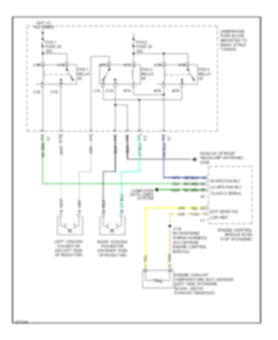
3.6L VIN 7, Cooling Fan Wiring Diagram for Buick Allure Super 2008
 https://portal-diagnostov.com/license.html
Automotive Electricians Portal FZCO
Automotive Electricians Portal FZCO
https://portal-diagnostov.com/license.html
https://portal-diagnostov.com/license.html
Automotive Electricians Portal FZCO
Automotive Electricians Portal FZCOList of elements for 3.6L VIN 7, Cooling Fan Wiring Diagram for Buick Allure Super 2008:
- (in back of right headlamp on frame) g100
- A18
- A19
- C18
- C19
- Class 2 serial
- Computer data lines system
- E10
- Ect sens sig
- Engine control module (ecm) (top of engine)
- Engine coolant temperature (ect) sensor (left side of engine block, above exhaust manifold)
- Fan 1 fuse 29 30a
- Fan 1 relay
- Fan 2 fuse 32 30a
- Fan 2 relay
- Fan 3 relay
- Hi spd fan rly
- Hot at all times
- J119 (in on-engine wiring harness, 34.5 cm from engine control module)
- K14
- K15
- K18
- K19
- L14
- Left cooling fan motor (on left side of radiator)
- Lo spd fan rly
- Low ref
- M14
- M15
- M18
- M19
- Right cooling fan motor (on right side of radiator)
- Tan
- Underhood fuse block (mounted to right strut tower)
3.8L VIN 2
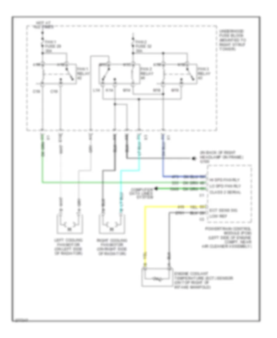
3.8L VIN 2, Cooling Fan Wiring Diagram for Buick Allure Super 2008
 https://portal-diagnostov.com/license.html
Automotive Electricians Portal FZCO
Automotive Electricians Portal FZCO
https://portal-diagnostov.com/license.html
https://portal-diagnostov.com/license.html
Automotive Electricians Portal FZCO
Automotive Electricians Portal FZCOList of elements for 3.8L VIN 2, Cooling Fan Wiring Diagram for Buick Allure Super 2008:
- (in back of right headlamp on frame) g100
- A18
- A19
- C18
- C19
- Class 2 serial
- Computer data lines system
- E10
- Ect sens sig
- Engine coolant temperature (ect) sensor (on top right of intake manifold)
- Fan 1 fuse 29 30a
- Fan 1 relay
- Fan 2 fuse 32 30a
- Fan 2 relay
- Fan 3 relay
- Hi spd fan rly
- Hot at all times
- K14
- K15
- K18
- K19
- L14
- Left cooling fan motor (on left side of radiator)
- Lo spd fan rly
- Low ref
- M14
- M15
- M18
- M19
- Powertrain control module (pcm) (left side of engine compt, near air cleaner assembly)
- Right cooling fan motor (on right side of radiator)
- Underhood fuse block (mounted to right strut tower)
5.3L VIN C
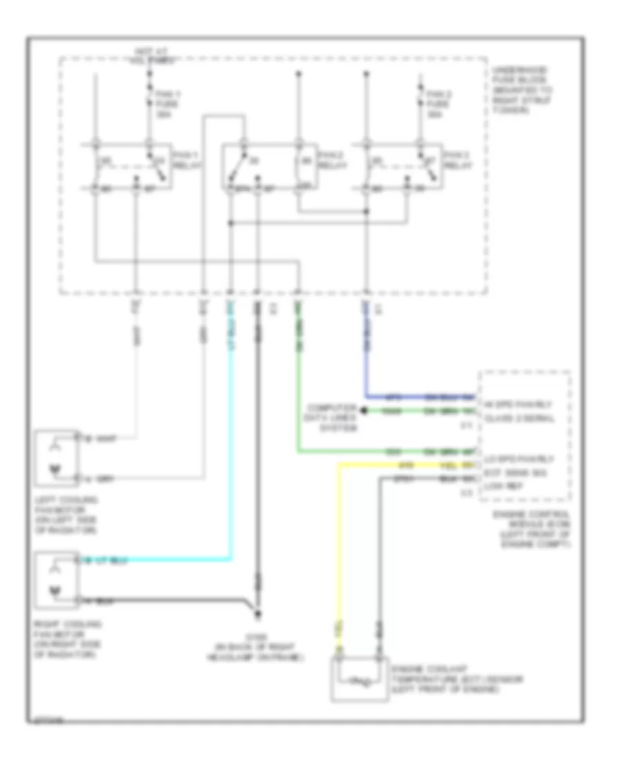
5.3L VIN C, Cooling Fan Wiring Diagram for Buick Allure Super 2008
 https://portal-diagnostov.com/license.html
Automotive Electricians Portal FZCO
Automotive Electricians Portal FZCO
https://portal-diagnostov.com/license.html
https://portal-diagnostov.com/license.html
Automotive Electricians Portal FZCO
Automotive Electricians Portal FZCOList of elements for 5.3L VIN C, Cooling Fan Wiring Diagram for Buick Allure Super 2008:
- 87a
- Class 2 serial
- Computer data lines system
- Ect sens sig
- Engine control module (ecm) (left front of engine compt)
- Engine coolant temperature (ect) sensor (left front of engine)
- Fan 1 fuse 30a
- Fan 1 relay
- Fan 2 fuse 30a
- Fan 2 relay
- Fan 3 relay
- G100 (in back of right headlamp on frame)
- Hi spd fan rly
- Hot at all times
- Left cooling fan motor (on left side of radiator)
- Lo spd fan rly
- Low ref
- Right cooling fan motor (on right side of radiator)
- Underhood fuse block (mounted to right strut tower)
CRUISE CONTROL
3.6L VIN 7
3.6L VIN 7, Cruise Control Wiring Diagram for Buick Allure Super 2008
 https://portal-diagnostov.com/license.html
Automotive Electricians Portal FZCO
Automotive Electricians Portal FZCO
https://portal-diagnostov.com/license.html
https://portal-diagnostov.com/license.html
Automotive Electricians Portal FZCO
Automotive Electricians Portal FZCOList of elements for 3.6L VIN 7, Cruise Control Wiring Diagram for Buick Allure Super 2008:
- (below dash, bolted to dash carrier) g201
- (in steering column wiring harness) j215
- 10 volt ref
- 5 volt reference 1
- 5 volt reference 2
- 5v ref
- A nca
- Accelerator pedal position (app) sensor (above accelerator pedal)
- App sensor 1 signal
- App sensor 2 signal
- B11
- Bat pos vol
- Bcm class 2 data
- Body control module (bcm) (behind left side of dash, left of steering column)
- Brake pedal position sensor (under left side of dash, on right side of brake pedal)
- C nca
- Clstr fuse 10a
- Computer data lines system
- Cruise can sw sig
- Cruise fuse 2a
- Cruise indicator
- Cruise switch
- D nca
- D pnk
- Driver information center (dic) display
- E10
- E12
- Ecm class 2 ser data
- Engine control module (ecm) (top of engine)
- F11
- Gmlan serial bus+
- Gmlan serial bus-
- Ground distribution system
- H nca
- Hot at all times
- Hot in run or start
- I/p fuse block (behind right side of dash)
- Ign
- Inflatable restraint steering wheel module coil (in steering column)
- Instrument panel cluster (ipc)
- Ipc class 2 ser data
- Left steering wheel controls
- Logic
- Low ref
- Low reference
- Nca
- On ind
- Pnk
- Rear object sensor control module
- Res +
- Set -
- Set/coast resume/ accelerate signal
- Stop lamp sig
- Stop switch sig
- Tac mtr ctrl 1
- Tac mtr ctrl 2
- Tan
- Throttle actuator control (tac) module (at throttle body)
- Tp sens 1 sig
- Tp sens 2 sig
- Transmission control module (tcm) (inside air cleaner, left front of engine compt)
- Underhood fuse block (mounted to right strut tower)
- Veh spd sig
- Vehicle speed sensor (vss) (right side of transmission, near right axle shaft)
- Vehicle speed signal
- Vss high sig
- Vss low sig
3.8L VIN 2
3.8L VIN 2, Cruise Control Wiring Diagram for Buick Allure Super 2008
 https://portal-diagnostov.com/license.html
Automotive Electricians Portal FZCO
Automotive Electricians Portal FZCO
https://portal-diagnostov.com/license.html
https://portal-diagnostov.com/license.html
Automotive Electricians Portal FZCO
Automotive Electricians Portal FZCOList of elements for 3.8L VIN 2, Cruise Control Wiring Diagram for Buick Allure Super 2008:
- (below dash, bolted to dash carrier) g201
- (in steering column wiring harness) j215
- 10 volt ref
- 5 volt ref
- A nca
- Accelerator pedal position (app) sensor (above accelerator pedal)
- App sens 1 sig
- App sens 2 sig
- B11
- Bat pos vol
- Bcm class 2 data
- Body control module (bcm) (behind left side of dash, left of steering column)
- Brake pedal position sensor (under left side of dash, on right side of brake pedal)
- C nca
- Clstr fuse 10a
- Computer data lines system
- Cruise can sw sig
- Cruise fuse 2a
- Cruise indicator
- Cruise switch
- D nca
- D pnk
- Driver information center (dic) display
- E10
- E12
- F11
- Ground distribution system
- H nca
- Hot at all times
- Hot in run or start
- I/p fuse block (behind right side of dash)
- Ign
- Inflatable restraint steering wheel module coil (in steering column)
- Instrument panel cluster (ipc)
- Ipc class 2 ser data
- Left steering wheel controls
- Logic
- Low ref
- Nca
- On ind
- Pnk
- Powertrain control module (left side of engine compt, near air cleaner assembly)
- Rear object sensor control module
- Res +
- Ser data primary
- Ser data secondary
- Set -
- Set/coast resume/ accelerate signal
- Stop lamp sig
- Stop lamp sw sig
- Stop switch sig
- Tan
- Throttle actuator control (tac) module (at throttle body)
- Underhood fuse block (mounted to right strut tower)
- Veh spd sig
- Vehicle speed sensor (vss) (right side of transmission, near right axle shaft)
- Vehicle speed signal
- Vss high signal
- Vss low signal
5.3L VIN C
5.3L VIN C, Cruise Control Wiring Diagram for Buick Allure Super 2008
 https://portal-diagnostov.com/license.html
Automotive Electricians Portal FZCO
Automotive Electricians Portal FZCO
https://portal-diagnostov.com/license.html
https://portal-diagnostov.com/license.html
Automotive Electricians Portal FZCO
Automotive Electricians Portal FZCOList of elements for 5.3L VIN C, Cruise Control Wiring Diagram for Buick Allure Super 2008:
- (below dash, bolted to dash carrier) g201
- (in steering column wiring harness) j215
- (left side of engine compt, part of brake pressure modulator valve) electronic brake control module (ebcm)
- 10 volt ref
- 5 volt ref 1
- 5 volt ref 2
- 5v ref 2
- A nca
- Accelerator pedal position (app) sensor (above accelerator pedal)
- App sensor 1 sig
- App sensor 2 sig
- Bat pos vol
- Bcm class 2 data
- Body control module (bcm) (behind left side of dash, left of steering column)
- Brake pedal position sensor (under left side of dash, on right side of brake pedal)
- C nca
- Clstr fuse 10a
- Computer data lines system
- Cruise can sw sig
- Cruise ctrl sw sig
- Cruise fuse 2a
- Cruise indicator
- Cruise on ind
- Cruise switch
- D nca
- D pnk
- Driver information center (dic) display
- E10
- E12
- Ecm class 2 ser data
- Engine control module (ecm) (left front of engine compt)
- Gmlan serial bus+
- Gmlan serial bus-
- Ground distribution system
- H nca
- Hot at all times
- Hot in run or start
- I/p fuse block (behind right side of dash)
- Ign
- Inflatable restraint steering wheel module coil (in steering column)
- Instrument panel cluster (ipc)
- Ipc class 2 ser data
- Left steering wheel controls
- Logic
- Low ref
- Nca
- Pnk
- Rear object sensor control module
- Res +
- Set -
- Stop lamp sig
- Stop switch sig
- Tac mtr ctrl 1
- Tac mtr ctrl 2
- Tan
- Throttle actuator control (tac) module (top rear of engine)
- Tp sens 1 sig
- Tp sens 2 sig
- Transmission control module (tcm) (left front of engine compt)
- Underhood fuse block (mounted to right strut tower)
- Veh spd sig
- Vehicle speed sensor (vss) (right side of transmission, near right axle shaft)
- Vehicle speed signal
- Vss high sig
- Vss low sig
- X4 h2
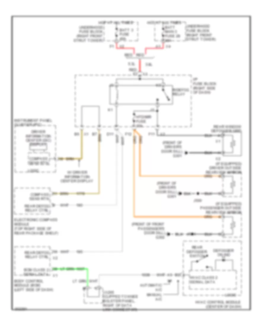
DEFOGGERS
Defoggers Wiring Diagram for Buick Allure Super 2008
 https://portal-diagnostov.com/license.html
Automotive Electricians Portal FZCO
Automotive Electricians Portal FZCO
https://portal-diagnostov.com/license.html
https://portal-diagnostov.com/license.html
Automotive Electricians Portal FZCO
Automotive Electricians Portal FZCOList of elements for Defoggers Wiring Diagram for Buick Allure Super 2008:
- (front of driver's door sill) g301
- (front of front passenger's door sill) g302
- (if equipped) driver outside rearview mirror
- (if equipped) passenger outside rearview mirror
- 3.8l
- 5.3l
- Automatic a/c
- Batt 3 fuse 40a
- Bcm class 2 serial data x1
- Body control module (bcm) (left side of dash)
- Compass sens rtn
- Defogger on ind
- Driver information center (dic) display
- Electronic compass module (top right side of rear package shelf)
- F11
- Hot at all times
- Hot at all times batt main 3 fuse 28 40a
- Htd/mir fuse 10a
- Hvac class 2 serial data
- Hvac control module (center of dash)
- I/p fuse block (right side of dash)
- Instrument panel cluster (ipc)
- J500
- J604
- Jx205 (clipped to knee bolster panel, right of data link connector)
- Logic
- Manual a/c
- R/defog relay
- Rear defog relay ctrl
- Rear defog relay ctrl x2
- Rear defogger switch
- Rear window defogger grid
- Red
- Red f3
- Underhood fuse block (right front strut tower)
- W/ driver information center display
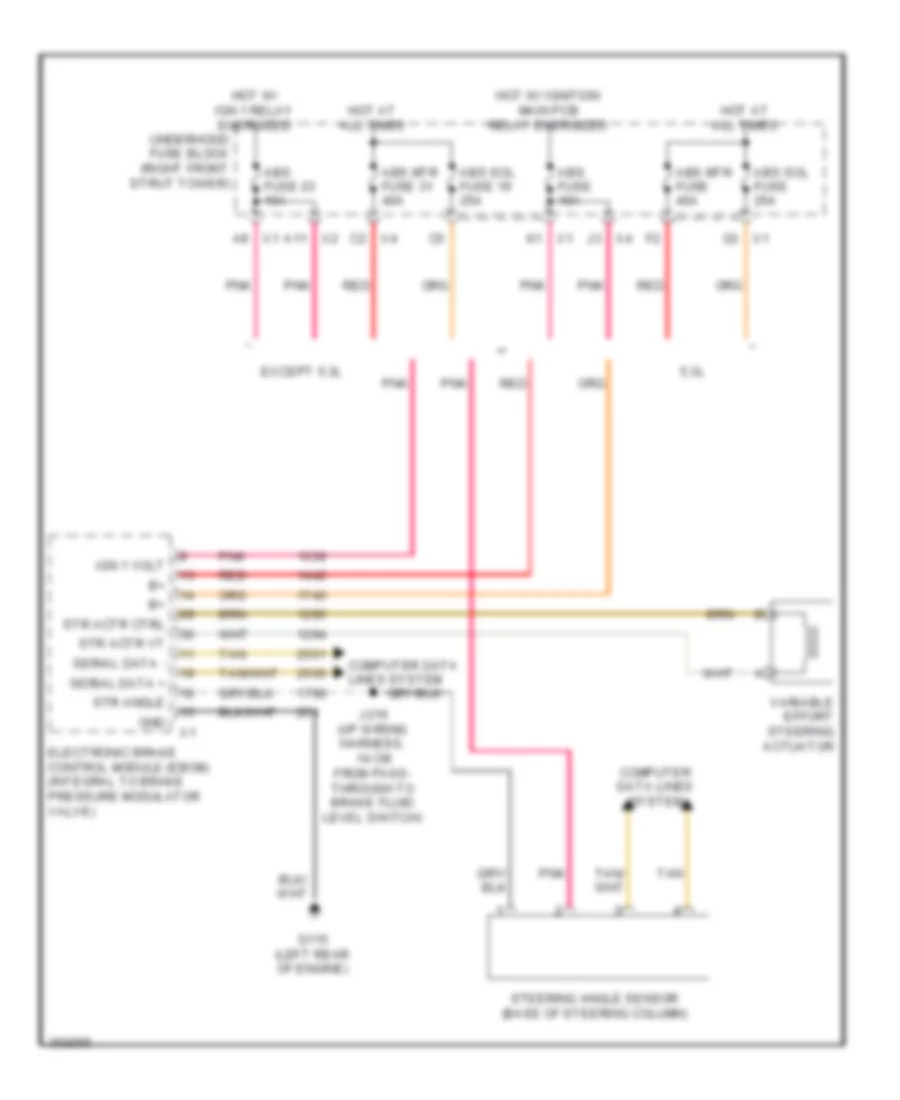
ELECTRONIC POWER STEERING
Electronic Power Steering Wiring Diagram for Buick Allure Super 2008
 https://portal-diagnostov.com/license.html
Automotive Electricians Portal FZCO
Automotive Electricians Portal FZCO
https://portal-diagnostov.com/license.html
https://portal-diagnostov.com/license.html
Automotive Electricians Portal FZCO
Automotive Electricians Portal FZCOList of elements for Electronic Power Steering Wiring Diagram for Buick Allure Super 2008:
- 5.3l
- A9 x1
- Abs fuse 10a
- Abs fuse 23 10a
- Abs mtr fuse 31 40a
- Abs mtr fuse 40a
- Abs sol fuse 19 25a
- Abs sol fuse 25a
- C2 x4
- Computer data lines system
- Electronic brake control module (ebcm) (integral to brake pressure modulator valve)
- Except 5.3l
- G115 (left rear of engine)
- G3 x1
- Gnd
- Hot at all times
- Hot w/ ign 1 relay energized
- Hot w/ ignition main pcb relay energized
- Ign 1 volt
- J216 (i/p wiring harness, 14 cm from pass- through to brake fluid level switch)
- J3 x4
- K1 x1
- Pnk
- Red
- Serial data +
- Serial data -
- Steering angle sensor (base of steering column)
- Str actr ctrl
- Str actr vt
- Str angle
- Tan
- Underhood fuse block (right front strut tower)
- Variable effort steering actuator
- X2 a11
ENGINE PERFORMANCE
3.6L VIN 7
3.6L VIN 7, Engine Performance Wiring Diagram (1 of 4) for Buick Allure Super 2008
 https://portal-diagnostov.com/license.html
Automotive Electricians Portal FZCO
Automotive Electricians Portal FZCO
https://portal-diagnostov.com/license.html
https://portal-diagnostov.com/license.html
Automotive Electricians Portal FZCO
Automotive Electricians Portal FZCOList of elements for 3.6L VIN 7, Engine Performance Wiring Diagram (1 of 4) for Buick Allure Super 2008:
- (1: right top of engine) (2: left top of engine) (3: right top center of engine) (4: left top center of engine) (5: right top rear of engine) (6: left top rear of engine)
- +5v
- +5v ref
- +5v ref 2
- Bare
- Ckp sens sig
- Cmp sig
- Cmp sol ctrl
- Crankshaft (ckp) position sensor (right rear of engine block)
- Ect sig
- Engine control module (top of engine)
- Engine oil pressure (eop) switch
- Evap sol ctrl
- Fuel injectors
- G103 (redundant ground from ecm to even bank cylinder head)
- G115 (mounted to bank 1 cylinder head above exhaust manifold)
- Gen fdc sig
- Gen to sig
- Gnd
- Ground
- Heated oxygen sensor 1 (at rear of cylinder head, in exhaust manifold)
- Heated oxygen sensor 2 (in exhaust system, rear of catalytic converter)
- Ho2s hi sig
- Ho2s lo ctrl
- Ho2s pmp ct
- Ign 1 ctrl
- Ign 2 ctrl
- Ign 3 ctrl
- Ign 4 sig
- Ign 5 ctrl
- Ign 6 ctrl
- Inj 1 ctrl
- Inj 2 ctrl
- Inj 3 ctrl
- Inj 4 ctrl
- Inj 5 ctrl
- Inj 6 ctrl
- J104
- J108
- Knock sensor (ks) 1 (right side of engine)
- Knock sensor (ks) 2 (left side of engine block, below exhaust manifold)
- Ks 1 sig
- Ks 2 sig
- Low ref
- Map sig
- Nca
- Oil pres sig
- Pnk
- Pnk e
- Starting/ charging system
- Tac mtr ctrl-1
- Tac mtr ctrl-2
- Tan
- Tp sig
- Tp2 sig
3.6L VIN 7, Engine Performance Wiring Diagram (2 of 4) for Buick Allure Super 2008
 https://portal-diagnostov.com/license.html
Automotive Electricians Portal FZCO
Automotive Electricians Portal FZCO
https://portal-diagnostov.com/license.html
https://portal-diagnostov.com/license.html
Automotive Electricians Portal FZCO
Automotive Electricians Portal FZCOList of elements for 3.6L VIN 7, Engine Performance Wiring Diagram (2 of 4) for Buick Allure Super 2008:
- (on cylinder head)
- (on left valve cover)
- (on right valve cover)
- A11
- C11
- Cnstr fuse 10a
- D11
- Elek ign fuse 15a
- Emis- sion fuse 10a
- Etc fuse 17 15a
- F12
- Fuel inj fuse 15a
- Fuel pp fuse 22 15a
- Fuel pump relay
- G115 (mounted to bank 1 cylinder head above exhaust manifold)
- G130 (on cylinder head, front of engine)
- G131
- Hot at all times
- Hot in run or start
- I/p fuse block (behind right side of dash)
- Ign 1 relay
- Ignition coil 1
- Ignition coil 2
- Ignition coil 3
- Ignition coil 4
- Ignition coil 5
- Ignition coil 6
- J103
- J106
- J110
- J116
- J130
- J131
- J132
- J133
- Nca
- O2 ssr fuse 15a
- P/train relay
- Pcm fuse 15 10a
- Pcm/etc fuse 16 15a
- Pnk
- Spark plug
- Tan
- Under- hood fuse block (mounted to right strut tower)
3.6L VIN 7, Engine Performance Wiring Diagram (3 of 4) for Buick Allure Super 2008
 https://portal-diagnostov.com/license.html
Automotive Electricians Portal FZCO
Automotive Electricians Portal FZCO
https://portal-diagnostov.com/license.html
https://portal-diagnostov.com/license.html
Automotive Electricians Portal FZCO
Automotive Electricians Portal FZCOList of elements for 3.6L VIN 7, Engine Performance Wiring Diagram (3 of 4) for Buick Allure Super 2008:
- (in on-engine wiring harness, 34.5 cm from engine control module)
- (on front of left cylinder head)
- (on front of right cylinder head)
- +5v
- A/c refrigerant pressure sensor (on left side of engine compt, on accumulator)
- Bank 2)
- Barometric pressure (baro) sensor
- Camshaft position actuator solenoid (exhaust bank 1)
- Camshaft position actuator solenoid (exhaust bank 2)
- Camshaft position actuator solenoid (intake bank 1)
- Camshaft position actuator solenoid (intake bank 2)
- Camshaft position sensor (exhaust bank 1)
- Camshaft position sensor (exhaust bank 2)
- Camshaft position sensor (intake
- Camshaft position sensor (intake bank 1)
- Engine coolant temperature sensor (left side of engine block, above exhaust manifold)
- Evaporative emission (evap) canister purge solenoid valve (top center of engine)
- J119
- Low ref
- Mass air flow/ intake air temperature sensor (in air intake tube)
- Pnk
- Signal
- Tan
- Throttle actuator control module (at throttle body)
3.6L VIN 7, Engine Performance Wiring Diagram (4 of 4) for Buick Allure Super 2008
 https://portal-diagnostov.com/license.html
Automotive Electricians Portal FZCO
Automotive Electricians Portal FZCO
https://portal-diagnostov.com/license.html
https://portal-diagnostov.com/license.html
Automotive Electricians Portal FZCO
Automotive Electricians Portal FZCOList of elements for 3.6L VIN 7, Engine Performance Wiring Diagram (4 of 4) for Buick Allure Super 2008:
- (ims)
- (in fuel tank) fuel pump & sender assembly
- (in fuel tank) fuel tank pressure (ftp) sensor
- (in off-engine wiring harness, 32 cm from underhood fuse block towards transmission control module)
- (mounted to bank 1 cylinder head above exhaust manifold) g115
- +5v ref 1
- +5v ref 2
- A/c ref pres
- A12
- Acc
- Accelerator pedal (app) position sensor (above accelerator pedal)
- Air conditioning system
- Anti-lock brake system
- App sens 2 sig
- App sens sig
- Automatic transmission
- Automatic transmission internal
- B12
- Battery +
- Body control module (bcm) (below left side of dash, left of steering column)
- C12
- Cc sw sig
- Class 2 data
- Clu rly ctrl
- Computer data lines system
- Cooling fans system
- Cruise control system
- D10
- D12
- Delv torque sig
- E11
- Eng spd sig
- Engine control module (ecm) (top of engine)
- Evap sol ctrl
- Evaporative emissions (evap) canister vent solenoid valve (behind left side of rear fascia splash shield, behind wheelwell)
- Fan rly ctrl
- Fuel lev sig
- Fuel level sensor
- G302 (in right door sill, forward of right front seat)
- Gmlan bus+
- Gmlan bus-
- Ho2s hi sig
- Ho2s lo ctrl
- Ho2s lo sig
- Hot at all times
- I/p fuse block (behind right side of dash)
- I/p fuse block (behind right x1 side of dash)
- Iat sig
- Ign
- Ign 1 volt
- Ign 3 volt
- Ignition switch
- Instrument panel cluster
- J116
- J118
- Lan bus +
- Lan bus -
- Lock
- Logic
- Low ref
- Maf sig
- Main rly ctrl
- Malfunction indicator lamp
- Mil ctrl
- Mode switch
- Navigation system
- P/n
- P/n sig
- Pnk
- Req torq sig
- Rly coil ctrl
- Rly ctrl
- Run
- Start
- Starting/ charging system
- Stop lamp sw sig
- Stop lp sw
- Tan
- Tank pres sig
- Transmission control module (inside air cleaner, left front of engine compartment)
- Underhood fuse block (mounted to right strut tower)
- Underhood fuse block (mounted to right strut tower) x1
- Underhood fuse block (mounted to right strut x1 tower)
- Underhood fuse block x1 (mounted to right strut tower)
- Vss
3.8L VIN 2
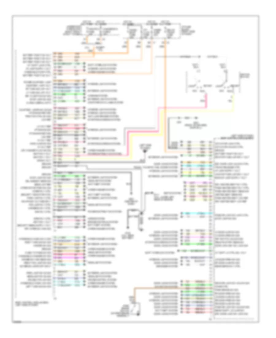
3.8L VIN 2, Engine Performance Wiring Diagram (1 of 5) for Buick Allure Super 2008
 https://portal-diagnostov.com/license.html
Automotive Electricians Portal FZCO
Automotive Electricians Portal FZCO
https://portal-diagnostov.com/license.html
https://portal-diagnostov.com/license.html
Automotive Electricians Portal FZCO
Automotive Electricians Portal FZCOList of elements for 3.8L VIN 2, Engine Performance Wiring Diagram (1 of 5) for Buick Allure Super 2008:
- (lower front center of engine oil pan) engine oil level switch
- (lower left front of engine, on transmission stud, near starter) g113
- (pins 62-72 not used)
- (top right rear of engine, near throttle body) exhaust gas recirculation valve
- (top right side of intake manifold) manifold absolute pressure sensor
- 5 volt ref 1
- Air sol ctrl
- Cmp sensor
- Ect sensor sig
- Egr pos sig
- Egr sol high
- Egr sol low
- Engine coolant temperature sensor (on top right of intake manifold)
- Engine oil pressure (eop) switch
- Evap purge sol
- Evaporative emission (evap) canister purge solenoid valve (top rear of engine)
- Fuel inj 1
- Fuel inj 2
- Fuel inj 3
- Fuel inj 4
- Fuel inj 5
- Fuel inj 6
- Fuel injectors (1: left top of engine) (2: right top of engine) (3: left top center of engine) (4: right top center of engine) (5: left top rear of engine) (6: right top rear of engine)
- G113 (lower left front of engine, on transmission stud, near starter)
- Gen field
- Gen on sig
- Generator
- Ground
- Heated oxygen sensor (ho2s) 1 (right side of engine)
- Ho2s heater 1
- Ho2s sig high
- Ho2s sig low
- Ic timing ctrl
- Ic timing sig
- J101
- J109
- Knock sensor (ks) 1 (front left side of engine)
- Knock sensor (ks) 2 (right side of engine, below exhaust manifold)
- Knock sensor 1
- Knock sensor 2
- Low eng speed
- Low ref
- Map sensor sig
- Med eng speed
- Nca
- Oil level sw
- Oil press sig
- Pnk
- Powertrain control module (left side of engine compartment, near air cleaner assembly)
- Red
- Tan
- Uart data
3.8L VIN 2, Engine Performance Wiring Diagram (2 of 5) for Buick Allure Super 2008
 https://portal-diagnostov.com/license.html
Automotive Electricians Portal FZCO
Automotive Electricians Portal FZCO
https://portal-diagnostov.com/license.html
https://portal-diagnostov.com/license.html
Automotive Electricians Portal FZCO
Automotive Electricians Portal FZCOList of elements for 3.8L VIN 2, Engine Performance Wiring Diagram (2 of 5) for Buick Allure Super 2008:
- (front of engine) camshaft position sensor
- (in ignition control module wiring harness, on top of engine near ignition control module, 12 cm from inline connector x110 breakout, towards icm)
- (in ignition control module wiring harness, on top of engine near ignition control module, 5.5 cm from inline connector x110 breakout, towards icm)
- (in right side of engine, on ignition control module bracket)
- (lower left front of engine) crankshaft position sensor
- (top left front of engine) ignition control module (icm)
- 5 volt ref
- A11
- Aap sensor 1
- Accelerator pedal position sensor (above accelerator pedal)
- App sensor 2
- Body control module (behind left side of dash, left of steering column)
- C11
- Elek ign fuse 24 15a
- Etc fuse 17 15a
- From p/train relay (diagram 4 of 5)
- Fuel inj fuse 20 15a
- G112
- G113 (lower left front of engine, on transmission stud, near starter)
- Ground
- Hot in run or start
- Ign 1 volt
- Ignition coil/ module
- J101
- J102
- J144
- J145
- Low ref
- Pnk
- Primary uart
- Sec uart
- Secondary air injection control solenoid valve/pressure sensor bank 2 (pzev) (top of engine, above valve cover)
- Secondary air injection solenoid relay (pzev) (near air cleaner duct)
- Spark plugs
- Stop lamp
- Stop lamp switch signal
- Tan
- Throttle actuator control (tac) module (at throttle body)
- Trans sol fuse 21 10a
- Underhood fuse block (mounted to right strut tower)
- Vehicle spd
3.8L VIN 2, Engine Performance Wiring Diagram (3 of 5) for Buick Allure Super 2008
 https://portal-diagnostov.com/license.html
Automotive Electricians Portal FZCO
Automotive Electricians Portal FZCO
https://portal-diagnostov.com/license.html
https://portal-diagnostov.com/license.html
Automotive Electricians Portal FZCO
Automotive Electricians Portal FZCOList of elements for 3.8L VIN 2, Engine Performance Wiring Diagram (3 of 5) for Buick Allure Super 2008:
- (in automatic transmission wiring harness, inside transmission housing, 19 cm from inline connector x113)
- 1-2 shift solenoid
- 2-3 shift solenoid
- A red
- A/t fluid pressure (tfp) manual position switch
- A/t fluid temperature sensor
- Air pres sens
- At iss sig
- Automatic transmission
- B tan
- G113 (lower left front of engine, on transmission stud, near starter)
- Ho2s heater 2
- Ho2s sig high
- Ho2s sig low
- Iat sensor sig
- Input shaft speed sensor
- Low ref
- Maf sensor sig
- Pc sol
- Pnk
- Powertrain control module (left side of engine compartment, near air cleaner assembly)
- Pressure control solenoid
- Red j115
- Shift sol
- Tan
- Tcc sol
- Tcc sw sig
- Tft sensor sig
- Torque converter clutch solenoid
- Torque sig
- Tr sw a
- Tr sw b
- Tr sw c
- Tr sw p
- Transmission internal mode switch
- Vehicle speed sensor (vss) assembly (right side of transmission, near right axle shaft)
- Vss sig
- W (not used)
3.8L VIN 2, Engine Performance Wiring Diagram (4 of 5) for Buick Allure Super 2008
 https://portal-diagnostov.com/license.html
Automotive Electricians Portal FZCO
Automotive Electricians Portal FZCO
https://portal-diagnostov.com/license.html
https://portal-diagnostov.com/license.html
Automotive Electricians Portal FZCO
Automotive Electricians Portal FZCOList of elements for 3.8L VIN 2, Engine Performance Wiring Diagram (4 of 5) for Buick Allure Super 2008:
- (at rear of engine, in air cleaner duct) intake air temperature/ mass air flow sensor
- Air pump fuse 25 50a
- Cnstr fuse 10a
- D11
- Electronic brake control (ebcm) module (left side of engine compt, part of brake pressure modulator valve)
- Emission fuse 12 10a
- Evaporative emissions (evap) canister vent solenoid valve (behind left side of rear fascia splash shield, behind wheelwell)
- F12
- Fuel pp fuse 22 15a
- Fuel pp relay
- G113 (lower left front of engine, on transmission stud, near starter)
- G115 (on transmission stud, to right of starter)
- Heated oxygen sensor (ho2s) 2 (in exhaust system, rear of catalytic converter)
- Hot at all times
- I/p fuse block (behind right side of dash)
- Iat
- J101
- J114
- J117
- Nca
- O2 ssr fuse 14 15a
- P/train relay
- Pnk
- Red
- Secondary air injection pump (pzev) (near transmission stud, left of starter)
- Secondary air injection pump relay (pzev) (near air cleaner duct)
- Tan
- To etc fuse 17 (diagram 2 of 5)
- Underhood fuse block (mounted to right strut tower)
- W/o active brake control
3.8L VIN 2, Engine Performance Wiring Diagram (5 of 5) for Buick Allure Super 2008
 https://portal-diagnostov.com/license.html
Automotive Electricians Portal FZCO
Automotive Electricians Portal FZCO
https://portal-diagnostov.com/license.html
https://portal-diagnostov.com/license.html
Automotive Electricians Portal FZCO
Automotive Electricians Portal FZCOList of elements for 3.8L VIN 2, Engine Performance Wiring Diagram (5 of 5) for Buick Allure Super 2008:
- (clipped to knee bolster panel, right of data link connector) splice pack jx205
- (in right door sill, forward of right front seat) g302
- (left side of dash, at base of steering column)
- (on left side of engine compt, on accumulator) a/c refrigerant pressure sensor
- 5 volt ref 1
- 5 volt ref 2
- A/c clutch relay
- A/c press sig
- A12
- A7 x2
- Acc
- Air conditioning system
- B11
- B12
- Battery
- C12
- Class 2
- Class 2 data
- Clstr fuse 10a
- Computer data lines system
- Cooling fans system
- Cruise control system
- Cruise sig
- D1 x1
- D10
- D12 x2
- Data link connector (under left side of dash)
- E11
- Eng speed sig
- Evap vent sol
- F x405
- F11
- Fuel level sig
- Fuel pump & sender assembly
- Fuel pump relay
- Fuel tank
- Fuel tank press
- Fuel tank pressure sensor
- G202
- Gnd
- High fan
- Hot at all times
- Hot in run or start
- I/p fuse block (behind right side of dash)
- Ign
- Ignition 1
- Ignition 3
- Ignition switch
- Instrument panel cluster
- J211
- Lock
- Logic
- Low fan
- Low ref
- Malfunction indicator lamp (mil)
- Mil control
- Navigation system
- Pcm fuse 10a
- Pcm relay
- Pcm/etc fuse 16 15a
- Pnk
- Powertrain control module (left side of engine compartment, near air cleaner assembly)
- Relay ctrl
- Run
- Serial data bus
- Start
- Starter enable
- Starting/charging system
- Stop lamp sw
- Underhood fuse block (mounted to right strut tower)
- Vehicle speed sig
- X1 d8
5.3L VIN C
5.3L VIN C, Engine Performance Wiring Diagram (1 of 5) for Buick Allure Super 2008
 https://portal-diagnostov.com/license.html
Automotive Electricians Portal FZCO
Automotive Electricians Portal FZCO
https://portal-diagnostov.com/license.html
https://portal-diagnostov.com/license.html
Automotive Electricians Portal FZCO
Automotive Electricians Portal FZCOList of elements for 5.3L VIN C, Engine Performance Wiring Diagram (1 of 5) for Buick Allure Super 2008:
- 5 volt ref 2
- 5-volt ref 1
- Ckp sensor sig
- Cmp sensor sig
- Emissions 1 fuse 15a
- Engine control module (ecm) (left front of engine compt)
- Etc/ecm fuse 10a
- From a pwr/trn relay (diagram 4 of 5)
- Fuel injector 1
- Fuel injector 2
- Fuel injector 3
- Fuel injector 4
- Fuel injector 5
- Fuel injector 6
- Fuel injector 7
- Fuel injector 8
- Ground
- Ho2s heater low
- Ho2s high signal
- Ho2s low signal
- Iat
- Iat sensor sig
- Ic 1 control
- Ic 2 control
- Ic 3 control
- Ic 4 control
- Ic 5 control
- Ic 6 control
- Ic 7 control
- Ic 8 control
- Ign 1 voltage
- Inj 1 fuse 20a
- Inj 2 fuse 20a
- Instrument cluster system
- J101
- Knock sensor (ks) 1
- Knock sensor (ks) 2 (lower right rear of engine)
- Knock sensor 1 signal
- Knock sensor 2 signal
- Low ref
- Maf sensor sig
- Mass air flow (maf)/ intake air temperature (iat) sensor (in air intake tube)
- Nca
- Oil pressure sw sig
- Red
- Stud, near starter) g113
- Tac motor control 1
- Tac motor control 2
- Tan
- Throttle actuator control (tac) module (top rear of engine)
- Tp sensor 1 sig
- Tp sensor 2 sig
- Underhood fuse block (mounted to right strut tower)
5.3L VIN C, Engine Performance Wiring Diagram (2 of 5) for Buick Allure Super 2008
 https://portal-diagnostov.com/license.html
Automotive Electricians Portal FZCO
Automotive Electricians Portal FZCO
https://portal-diagnostov.com/license.html
https://portal-diagnostov.com/license.html
Automotive Electricians Portal FZCO
Automotive Electricians Portal FZCOList of elements for 5.3L VIN C, Engine Performance Wiring Diagram (2 of 5) for Buick Allure Super 2008:
- (left top of engine)
- (on left valve cover)
- (right top of engine)
- (right top of engine) fuel injector
- (top left side of engine) fuel injector
- Fuel injector
- G112 (in right side of engine, on ignition control module bracket)
- Heated oxygen (ho2s) sensor 1 (right side of engine)
- Heated oxygen (ho2s) sensor 2 (in exhaust system, rear of catalytic converter)
- Ignition coil 1
- Ignition coil 3
- Ignition coil 5
- Ignition coil 7
- J108
- J109
- J130
- J134
- Nca
- Pnk d
- Pnk j106
- Red
- Red c
- Spark plug
- Tan
- Tan a
5.3L VIN C, Engine Performance Wiring Diagram (3 of 5) for Buick Allure Super 2008
 https://portal-diagnostov.com/license.html
Automotive Electricians Portal FZCO
Automotive Electricians Portal FZCO
https://portal-diagnostov.com/license.html
https://portal-diagnostov.com/license.html
Automotive Electricians Portal FZCO
Automotive Electricians Portal FZCOList of elements for 5.3L VIN C, Engine Performance Wiring Diagram (3 of 5) for Buick Allure Super 2008:
- (behind left side of rear fascia splash shield, behind wheelwell) evaporative emission (evap) canister vent solenoid valve
- (on left side of engine compt, on accumulator) a/c refrigerant pressure sensor
- (on right valve cover)
- (right rear of engine block)
- (top right rear of engine) evaporative emission (evap) canister purge solenoid valve
- A/c refrigerant
- Available) (info not
- Camshaft position (cmp) sensor
- Cnstr fuse 10a
- Crankshaft position (ckp) sensor
- Cylinder shutoff 4
- Cylinder shutoff 7
- Ect sensor sig
- Engine control module (ecm) (left front of engine compt)
- G112 (in right side of engine, on ignition control module bracket)
- Hot at all times
- I/p fuse block (behind right side of dash)
- Ignition coil 2
- Ignition coil 4
- Ignition coil 6
- Ignition coil 8
- J105
- J131
- J135
- Lines system computer data
- Map sensor sig
- Nca
- Pnk
- Pnk d
- Red
- Red c
- Serial data bus (+)
- Spark plug
- Underhood fuse block (mounted to right strut tower)
- Vehicle speed sig
5.3L VIN C, Engine Performance Wiring Diagram (4 of 5) for Buick Allure Super 2008
 https://portal-diagnostov.com/license.html
Automotive Electricians Portal FZCO
Automotive Electricians Portal FZCO
https://portal-diagnostov.com/license.html
https://portal-diagnostov.com/license.html
Automotive Electricians Portal FZCO
Automotive Electricians Portal FZCOList of elements for 5.3L VIN C, Engine Performance Wiring Diagram (4 of 5) for Buick Allure Super 2008:
- (top rear of engine) valve lifter oil manifold (vlom) assembly
- 5 volt ref 1
- Acc
- Brakes system anti-lock
- Cooling fans system
- Cylinder shutoff 1
- Cylinder shutoff 6
- Delivered torque
- Ecm ign fuse 10a
- Ecm/ tcm fuse 15a
- Emmis- sions 2 fuse 15a
- Engine control module (ecm) (left front of engine compt)
- Engine coolant temperature (ect) sensor (left front of engine)
- Evap canister purge
- Generator field
- Generator sig
- Hot at all times
- Hot w/ ignition main pcb relay energized
- Ignition switch
- Lines system computer data
- Lock
- Low ref
- Low speed cooling
- Manifold absolute pressure (map) sensor (top left rear of engine)
- Park/neutral sig
- Pnk
- Power distribution system
- Pwr/trn relay
- Red
- Requested torque
- Run
- Serial data bus (-)
- Shutoff cylinder solenoid 1, cylinder 1
- Shutoff cylinder solenoid 2, cylinder 4
- Shutoff cylinder solenoid 3, cylinder 6
- Shutoff cylinder solenoid 4, cylinder 7
- Start
- System charging starting/
- Tan
- To etc/ecm fuse (diagram 1 of 5)
- Transmissions system
- Underhood fuse block (mounted to right strut tower)
5.3L VIN C, Engine Performance Wiring Diagram (5 of 5) for Buick Allure Super 2008
 https://portal-diagnostov.com/license.html
Automotive Electricians Portal FZCO
Automotive Electricians Portal FZCO
https://portal-diagnostov.com/license.html
https://portal-diagnostov.com/license.html
Automotive Electricians Portal FZCO
Automotive Electricians Portal FZCOList of elements for 5.3L VIN C, Engine Performance Wiring Diagram (5 of 5) for Buick Allure Super 2008:
- (in right door sill, forward of right front seat) g302
- 5 volt ref 1
- 5 volt ref 2
- A/c compressor
- A12
- Acc voltage
- Accelerator pedal position (app) sensor (above accelerator pedal)
- Air conditioning system cooling fans system
- Anti-lock brakes system
- App sensor 1 sig
- App sensor 2 sig
- B12
- Batt pos voltage
- Brake booster sig
- Brake booster vacuum sensor (on brake booster)
- C12
- Class 2
- Clstr fuse 10a
- Computer data lines system
- Cooling fan rly
- Cruise control sw
- Cruise control system
- D1 x1
- D12 x2
- Engine control module (ecm) (left front of engine compt)
- Engine speed sig
- Evap canister vent
- Exterior lights system
- Fuel level sens
- Fuel pump & sender assembly
- Fuel pump rly
- Fuel tank
- Fuel tank pressure (ftp) sensor
- Fuel tank sens
- Fuel/ pump fuse 15a
- Fuel/ pump relay
- G113 (lower left front of engine, on transmission stud, near starter)
- G202 (left side of dash, at base of steering column)
- Gnd
- H6 x4
- Hot at all times
- I/p fuse block (behind right side of dash)
- Ign
- Ign 1 voltage
- Instrument panel cluster (ipc)
- J101
- J211
- Logic
- Low ref
- Low reference
- Mil control
- Mil ind
- Navigation system
- Pnk
- Powertrain rly
- Serial data
- Starter enable
- Starting/ charging system
- Stop lamp sw sig
- Tan
- Underhood fuse block (mounted to right strut tower)
- Vehicle speed sig
- X1 h1
- X2 c6
- X405 f
EXTERIOR LIGHTS
Exterior Lamps Wiring Diagram for Buick Allure Super 2008
 https://portal-diagnostov.com/license.html
Automotive Electricians Portal FZCO
Automotive Electricians Portal FZCO
https://portal-diagnostov.com/license.html
https://portal-diagnostov.com/license.html
Automotive Electricians Portal FZCO
Automotive Electricians Portal FZCOList of elements for Exterior Lamps Wiring Diagram for Buick Allure Super 2008:
- (left taillight wiring harness) j902
- (license lamp harness, near left license lamp) j402
- (right front strut tower) underhood fuse block
- (right taillight wiring harness) j903
- 10 volt ref
- 3.8l
- 5.3l
- Anti-lock brakes & engine controls systems
- Anti-lock brakes system
- Auto
- Batt positive volt
- Bcm class 2
- Bcm class 2 serial data
- Body control module (bcm) (left side of dash)
- Brake pedal position sensor (left side of dash)
- Center high mounted stop lamp (chmsl)
- Chmsl/ bkup fuse 15a
- Computer data lines system
- Driver information center (dic) switch
- G100 (right front of engine compt)
- G101 (left front of engine compt)
- G202 (left side of dash)
- G301 (front of driver's door sill)
- G302 (front of front passenger's door sill)
- H5 x1
- Hazard
- Hazard sw sig
- Hazrd fuse 20a
- Head
- Headlamp switch
- Hot at all times
- I/p fuse block (right side of dash)
- Ign
- Instrument panel cluster (ipc)
- Ipc class 2 serial data
- J111
- J112
- J113
- J124
- J211
- J214
- J401
- J406
- J900
- J901
- Left
- Left front marker lamp
- Left license lamp
- Left park/ turn signal lamp
- Left rear marker lamp
- Left tail/ stop & turn signal lamp
- Left turn indicator
- Left turn sw sig
- Logic
- Low ref
- Lower left tail lamp
- Lower right tail lamp
- Lr stop/turn volt
- Off
- Park
- Park lamp on sig
- Park lmp rly ctrl
- Prk lamp fuse 10a
- Prk/ lamp relay
- Right
- Right front marker lamp
- Right license lamp
- Right park/ turn signal lamp
- Right rear marker lamp
- Right tail/ stop & turn signal lamp
- Right turn indicator
- Right turn sw sig
- Rr stop/turn volt
- Splice pack jx307 (body wiring harness, under passenger seat, at rear carpet)
- Sply volt
- Stop lamp sw sig
- Tan
- Turn signal/ multi-function switch
- Upper left tail lamp
- Upper right tail lamp
- X1 c2
- X1 e2
- X1 f2
- X2 a2
- X2 a6
- X2 e11
- X2 f9
- X3 a9
- X3 c6
3.6L VIN 7
3.6L VIN 7, Backup Lamps Wiring Diagram for Buick Allure Super 2008
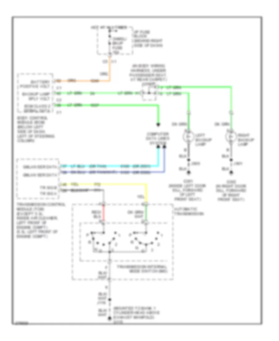 https://portal-diagnostov.com/license.html
Automotive Electricians Portal FZCO
Automotive Electricians Portal FZCO
https://portal-diagnostov.com/license.html
https://portal-diagnostov.com/license.html
Automotive Electricians Portal FZCO
Automotive Electricians Portal FZCOList of elements for 3.6L VIN 7, Backup Lamps Wiring Diagram for Buick Allure Super 2008:
- (in body wiring harness, under passenger seat, at rear carpet) jx407
- (mounted to bank 1 cylinder head above exhaust manifold) g115
- (or 2500)
- (or 2501)
- (or tan)
- Automatic transmission
- Backup lamp sply volt
- Battery positive volt
- Bcm class 2 serial data
- Body control module (bcm) (below left side of dash, left of steering column)
- Chmsl/ bkup fuse 15a
- Computer data lines system
- G301 (inside left door sill, forward of left front seat)
- G302 (in right door sill, forward of right front seat)
- Gmlan ser data
- Hot at all times
- I/p fuse block (behind right side of dash)
- J116
- J900
- J901
- Left backup lamp
- Right backup lamp
- Tr sig a
- Tr sig b
- Transmission control module (tcm) (except 5.3l: inside air cleaner, left front of engine compt) (5.3l: left front of engine compt)
- Transmission internal mode switch (ims)
3.8L VIN 2
3.8L VIN 2, Backup Lamps Wiring Diagram for Buick Allure Super 2008
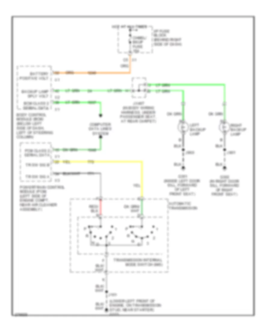 https://portal-diagnostov.com/license.html
Automotive Electricians Portal FZCO
Automotive Electricians Portal FZCO
https://portal-diagnostov.com/license.html
https://portal-diagnostov.com/license.html
Automotive Electricians Portal FZCO
Automotive Electricians Portal FZCOList of elements for 3.8L VIN 2, Backup Lamps Wiring Diagram for Buick Allure Super 2008:
- (lower left front of engine, on transmission stud, near starter) g113
- Automatic transmission
- Backup lamp sply volt
- Battery positive volt
- Bcm class 2 serial data
- Body control module (bcm) (below left side of dash, left of steering column)
- Chmsl/ bkup fuse 15a
- Computer data lines system
- G301 (inside left door sill, forward of left front seat)
- G302 (in right door sill, forward of right front seat)
- Hot at all times
- I/p fuse block (behind right side of dash)
- J101
- J900
- J901
- Jx407 (in body wiring harness, under passenger seat, at rear carpet)
- Left backup lamp
- Pcm class 2 serial data
- Powertrain control module (pcm) (left side of engine compt, near air cleaner assembly)
- Right backup lamp
- Tr sw sig a
- Tr sw sig b
- Transmission internal mode switch (ims)
5.3L VIN C
5.3L VIN C, Backup Lamps Wiring Diagram for Buick Allure Super 2008
 https://portal-diagnostov.com/license.html
Automotive Electricians Portal FZCO
Automotive Electricians Portal FZCO
https://portal-diagnostov.com/license.html
https://portal-diagnostov.com/license.html
Automotive Electricians Portal FZCO
Automotive Electricians Portal FZCOList of elements for 5.3L VIN C, Backup Lamps Wiring Diagram for Buick Allure Super 2008:
- (in body wiring harness, under passenger seat, at rear carpet) jx407
- (mounted to bank 1 cylinder head above exhaust manifold) g115
- (or 2500)
- (or 2501)
- (or tan)
- Automatic transmission
- Backup lamp sply volt
- Battery positive volt
- Bcm class 2 serial data
- Body control module (bcm) (below left side of dash, left of steering column)
- Chmsl/ bkup fuse 15a
- Computer data lines system
- G301 (inside left door sill, forward of left front seat)
- G302 (in right door sill, forward of right front seat)
- Gmlan ser data
- Hot at all times
- I/p fuse block (behind right side of dash)
- J116
- J900
- J901
- Left backup lamp
- Right backup lamp
- Tr sig a
- Tr sig b
- Transmission control module (tcm) (except 5.3l: inside air cleaner, left front of engine compt) (5.3l: left front of engine compt)
- Transmission internal mode switch (ims)
GROUND DISTRIBUTION
Ground Distribution Wiring Diagram (1 of 3) for Buick Allure Super 2008
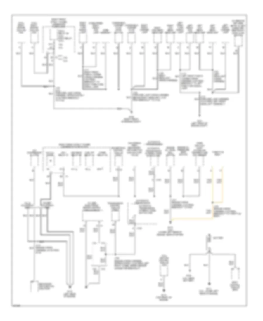 https://portal-diagnostov.com/license.html
Automotive Electricians Portal FZCO
Automotive Electricians Portal FZCO
https://portal-diagnostov.com/license.html
https://portal-diagnostov.com/license.html
Automotive Electricians Portal FZCO
Automotive Electricians Portal FZCOList of elements for Ground Distribution Wiring Diagram (1 of 3) for Buick Allure Super 2008:
- (3.8l) ignition control module (icm)
- (3.8l) right engine cooling fan
- (5.3l) right engine cooling fan
- (california pzev) secondary air injection (air) shutoff valve
- (engine wiring harness, approximately 5 cm from left front wheel speed sensor connector breakout)
- (if equipped) right front fog lamp
- (right front strut tower) underhood fuse block
- (w/ abs) electronic brake control module (ebcm)
- (w/ remote keyless entry & left cargo net restraint) hood ajar switch
- 3.8l
- 3.8l & california pzev
- 5.3l
- A/c clu diode
- A/c compressor clutch
- Automatic transmission
- Automatic transmission internal mode switch (ims)
- B b
- Battery
- Body control module (bcm)
- C11
- E15
- Engine oil level (eol) switch
- Engine oil pressure (eop) switch
- Except california pzev
- Fan 2 relay 46 (3.8l) fan 2 relay (5.3l)
- Fuel pp relay 41
- G100 (right front of engine compt)
- G101 (left front of engine compt)
- G102 (3.8l: near battery)
- G111 (3.8l: lower left rear of engine)
- G112 (top front of engine)
- G113 (3.8l) (lower left rear of engine, near starter)
- G115 (left rear of engine)
- Harness, 20 cm from g115)
- Harness, approximately 10 cm from breakout to x142)
- Hdm beam relay 35
- Horn assembly
- Ign 1 relay 37
- J101 (engine wiring harness, 5 cm from breakout to pcm)
- J102 (engine wiring harness, 5 cm from breakout to throttle body)
- J112 (forward lamp harness, 19 cm from left front headlight assembly)
- J124 (forward lamp wiring harness, behind right headlight, 5 cm from breakout to x142)
- J125
- J127 (left headlight wiring harness)
- Jumper wiring harness, 5 cm from breakout to left park/turn signal lamp)
- K14
- Left front fog lamp
- Left front marker lamp
- Left high beam headlamp
- Left low beam headlamp
- Left park/ turn signal lamp
- Mass air flow (maf)/ intake air temperature (iat) sensor
- Powertrain control module (pcm)
- Right front marker lamp
- Right high beam headlamp
- Right low beam headlamp
- Right park/ turn signal lamp
- Secondary air injection (air) pump
- Throttle body
- Transmission control module (tcm)
- Windshield washer fluid level switch
- Windshield washer fluid pump
- Wiper relay 45
- Wiring harness)
- X100
- X3 a5
Ground Distribution Wiring Diagram (2 of 3) for Buick Allure Super 2008
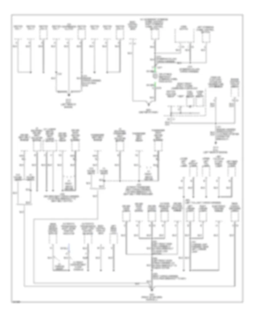 https://portal-diagnostov.com/license.html
Automotive Electricians Portal FZCO
Automotive Electricians Portal FZCO
https://portal-diagnostov.com/license.html
https://portal-diagnostov.com/license.html
Automotive Electricians Portal FZCO
Automotive Electricians Portal FZCOList of elements for Ground Distribution Wiring Diagram (2 of 3) for Buick Allure Super 2008:
- (if equipped) driver seat adjuster switch
- (if equipped) passenger seat adjuster switch
- (right front strut tower) underhood fuse block
- (w/ accessory steering wheel control) right steering wheel control switch
- (w/ lumbar seats) driver seat lumbar switch
- A/c compressor clutch
- Automatic transmission shift lever position indicator
- Automatic transmission shift lock control solenoid
- Body control module (bcm)
- Driver back heated seat element
- Driver door lock
- Driver door lock switch
- Driver heated seat relay
- Driver outside rearview mirror
- Driver seat belt buckle
- Driver window switch
- Electronic compass module
- Engine control module (ecm)
- Front
- Fuel/ pump relay
- G112 (5.3l) (left rear of engine)
- G113 (5.3l) (left rear of engine)
- G201 (center of dash)
- G301 (front of driver's door sill)
- Hdm
- Horn switch
- Ignition coil 1
- Ignition coil 2
- Ignition coil 3
- Ignition coil 4
- Ignition coil 5
- Ignition coil 6
- Ignition coil 7
- Ignition coil 8
- Ignition main pcb relay
- Inflatable restraint steering wheel module coil
- J130
- J131 (engine wiring harness, 30.5 cm from g130)
- J215 (steering column wiring harness)
- J303 (body wiring harness, 19 cm from breakout to g301)
- J330 (driver's seat wiring harness, 4.5 cm from breakout to seat belt switch)
- J333 (in front passenger seat wiring harness, 7 cm from breakout to seat belt pretensioner)
- J401 (license lamp harness, near left license lamp)
- J500 (left front door wiring harness, 8.5 cm from breakout to window motor)
- J900 (left taillight wiring harness)
- Left backup lamp
- Left license lamp
- Left rear door lock
- Left rear marker lamp
- Left steering wheel control switch
- Left tail/stop & turn signal lamp
- Lower left tail lamp
- Mass air flow (maf)/ intake air temperature (iat) sensor
- Nca
- Outside rearview mirror switch
- Passenger back heated seat element
- Passenger heat seat relay
- Passenger seat belt buckle
- Rear object sensor control module
- Rear window defogger grid
- Right license lamp
- Seats heater
- Upper left tail lamp
- W/ front compartment floor console
- W/ parking assist
- W/ power seats
- W/o power seats
- Wiper pcb relay
- Wiring harness)
- X2 a
- X2 b
- X275
- X277
Ground Distribution Wiring Diagram (3 of 3) for Buick Allure Super 2008
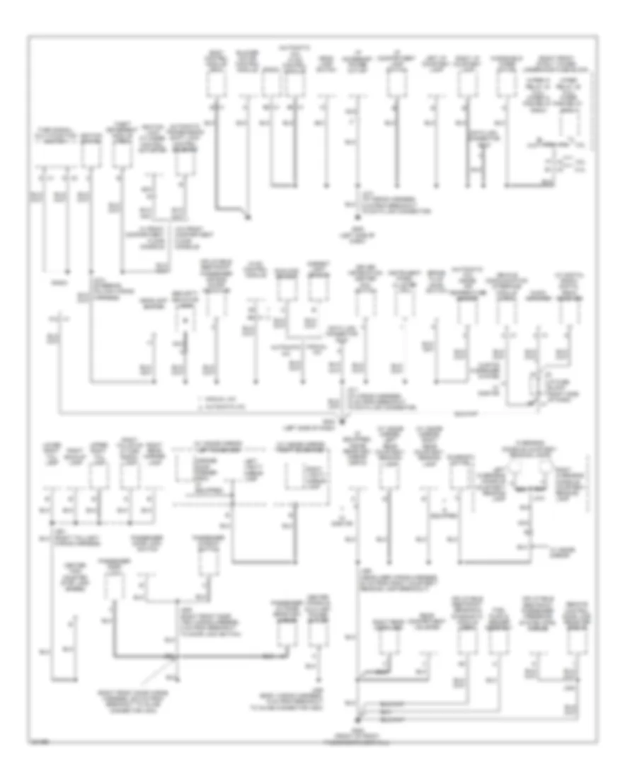 https://portal-diagnostov.com/license.html
Automotive Electricians Portal FZCO
Automotive Electricians Portal FZCO
https://portal-diagnostov.com/license.html
https://portal-diagnostov.com/license.html
Automotive Electricians Portal FZCO
Automotive Electricians Portal FZCOList of elements for Ground Distribution Wiring Diagram (3 of 3) for Buick Allure Super 2008:
- (automatic a/c) hvac control module
- (automatic a/c) inside air temperature sensor
- (if equipped) inside rearview mirror (isrvm)
- (right front door wiring harness, 25.5 cm from breakout to inline connector x304)
- (right front strut tower) underhood fuse block
- (w/ digital radio) digital radio receiver
- (w/ inside mirror) left rear courtesy/ reading lamp
- (w/ inside mirror) left sunshade
- (w/ inside mirror) right rear courtesy/ reading lamp
- (w/ inside mirror) right sunshade
- 3.8l
- 5.3l
- A12 x1
- A15
- Ambient light sensor
- Audio amplifier
- Automatic a/c
- Automatic transmission shift lock control solenoid
- B1 x2
- B5 x1
- B8 x1
- Blower motor control module
- Body control module (bcm)
- Brake fluid level switch
- Center console auxiliary power outlet
- Center high mounted stop lamp (chmsl)
- Custom 9 speaker system
- D x1
- Data link connector (dlc)
- Driver information center (dic) switch
- F14
- F7 x2
- Fuel pump & sender assembly
- G200 (left side of dash)
- G202 (left side of dash)
- G302 (front of front passenger's door sill)
- Garage door opener (gdo) (if equipped)
- Head- lamp switch
- Headlamp switch
- Hvac control module
- I/p accessory power outlet
- I/p compartment lamp switch
- I/p fuse block (right side of dash)
- If equipped
- Ignition lock cylinder control actuator
- Ignition switch
- Inflatable restraint passenger air bag on/off indicator
- Inflatable restraint passenger presence system (pps) module
- Inflatable restraint sensing & diagnostic module (sdm)
- Instrument panel cluster (ipc)
- J211 (i/p wiring harness, 10 cm from breakout to data link connector)
- J213 (i/p wiring harness, 5 cm from breakout to data link connector)
- J300
- J310
- J390 (headliner wiring harness, 20 cm from right courtesy/ reading lamp breakout)
- J406 (body wiring harness, 9 cm from breakout to inline connector x800)
- J604
- J605 (right front door trim wiring harness, 5 cm from breakout to door lock switch)
- Left i/p courtesy lamp
- Left overhead console courtesy/ reading lamp
- Left vanity mirror lamp
- Lower right tail lamp
- Manual a/c
- Nca
- Overhead console courtesy/ reading lamps
- Passenger door lock
- Passenger door lock switch
- Passenger outside rearview mirror
- Passenger window switch
- Radio
- Rear compartment lid latch
- Remote control door lock receiver (rcdlr)
- Right backup lamp
- Right i/p courtesy lamp
- Right overhead console courtesy/ reading lamp
- Right rear door lock
- Right rear marker lamp
- Right tail/stop & turn signal lamp
- Right vanity mirror lamp
- Security indicator lamp
- Sunload sensor
- Sunroof motor
- Theft deterrent module (tdm)
- Turn signal/ multi-function switch
- Upper right tail lamp
- Vehicle communication interface module (vcim)
- W/ front compartment floor console
- W/ inside mirror
- W/ onstar
- W/o front compartment floor console
- Windshield wiper motor
- Wiper hi relay 44 (3.8l) wiper hi pcb relay (5.3l)
- Wiper relay 45 (3.8l) wiper pcb relay (5.3l)
- Wiring harness)
- X1 a6
- X2 g
HEADLIGHTS
3.6L VIN 7
3.6L VIN 7, Headlights Wiring Diagram for Buick Allure Super 2008
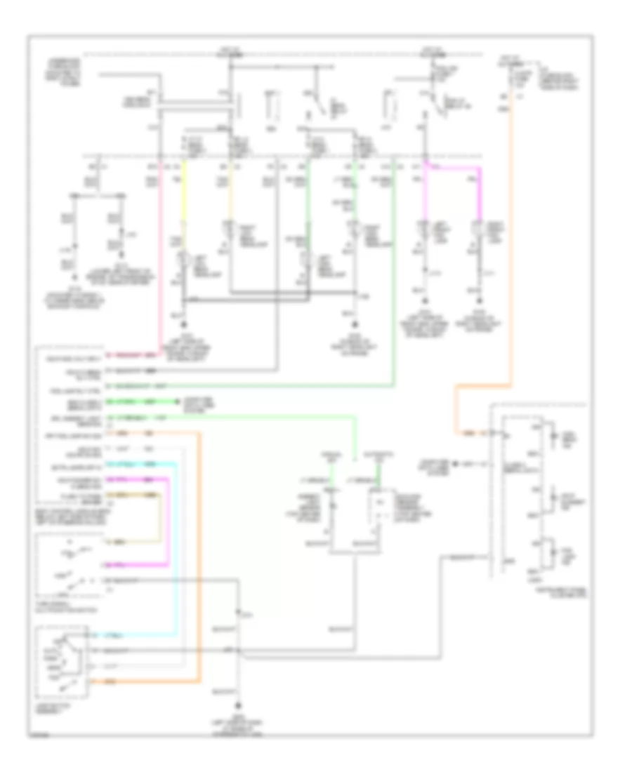 https://portal-diagnostov.com/license.html
Automotive Electricians Portal FZCO
Automotive Electricians Portal FZCO
https://portal-diagnostov.com/license.html
https://portal-diagnostov.com/license.html
Automotive Electricians Portal FZCO
Automotive Electricians Portal FZCOList of elements for 3.6L VIN 7, Headlights Wiring Diagram for Buick Allure Super 2008:
- 3.6l
- 3.8l
- A10
- A11
- A12
- Ambient light sensor (top center of dash)
- Auto
- Automatic a/c
- B11
- B12
- B3 x1
- Bcm
- Bcm class 2 serial data
- Body control module (bcm) (below left side of dash, left of steering column)
- C10
- C12
- Class 2 serial data
- Clstr fuse 10a
- Computer data lines system
- Drl ambient light sens sig x1
- E10 x2
- E19
- E20
- Extr lamps off in
- Flash to pass sw sig x3
- Fog
- Fog lamp ind
- Fog lamp rly ctrl
- Fog lp relay 36
- Fog lps fuse 7 10a
- Frt fog lamp sw sig
- Ftp
- G100 (in back of right headlight on frame)
- G101 (left side of front end upper tie bar, in back of headlight)
- G113 (lower left front of engine, on transmission stud, near starter)
- G115 (mounted to bank 1 cylinder head above exhaust manifold)
- G19
- G20
- G202 (left side of dash, at base of steering column)
- Gnd
- Hdlp dimmer sw hi beam sig
- Hdlp hi beam rly ctrl
- Hdlp mod volt sply
- Hdlp suggest ind
- Hdlp sw hdlps on sig
- Hdm beam module 35
- Head
- Hi beam relay
- High
- High beam ind
- Hot at all times
- I/p fuse block (behind right side of dash)
- Ign
- Instrument panel cluster (ipc)
- J101
- J111
- J113
- J116
- J126
- J127
- J211
- J214
- Lamp switch assembly
- Left front fog lamp
- Left high beam headlamp
- Left low beam headlamp
- Lf hi beam fuse 1 10a
- Lf lo beam fuse 3 10a
- Logic
- Low
- Manual a/c
- Off
- Park
- Rf hi beam fuse 2 10a
- Rf lo beam fuse 4 10a
- Right front fog lamp
- Right high beam headlamp
- Right low beam headlamp
- Sunload sensor assembly (top center of dash)
- Turn signal/ multifunction switch
- Underhood fuse block (mounted to right strut tower)
3.8L VIN 2
3.8L VIN 2, Headlights Wiring Diagram for Buick Allure Super 2008
 https://portal-diagnostov.com/license.html
Automotive Electricians Portal FZCO
Automotive Electricians Portal FZCO
https://portal-diagnostov.com/license.html
https://portal-diagnostov.com/license.html
Automotive Electricians Portal FZCO
Automotive Electricians Portal FZCOList of elements for 3.8L VIN 2, Headlights Wiring Diagram for Buick Allure Super 2008:
- 3.6l
- 3.8l
- A10
- A11
- A12
- Ambient light sensor (top center of dash)
- Auto
- Automatic a/c
- B11
- B12
- B3 x1
- Bcm
- Bcm class 2 serial data
- Body control module (bcm) (below left side of dash, left of steering column)
- C10
- C12
- Class 2 serial data
- Clstr fuse 10a
- Computer data lines system
- Drl ambient light sens sig x1
- E10 x2
- E19
- E20
- Extr lamps off in
- Flash to pass sw sig x3
- Fog
- Fog lamp ind
- Fog lamp rly ctrl
- Fog lp relay 36
- Fog lps fuse 7 10a
- Frt fog lamp sw sig
- Ftp
- G100 (in back of right headlight on frame)
- G101 (left side of front end upper tie bar, in back of headlight)
- G113 (lower left front of engine, on transmission stud, near starter)
- G115 (mounted to bank 1 cylinder head above exhaust manifold)
- G19
- G20
- G202 (left side of dash, at base of steering column)
- Gnd
- Hdlp dimmer sw hi beam sig
- Hdlp hi beam rly ctrl
- Hdlp mod volt sply
- Hdlp suggest ind
- Hdlp sw hdlps on sig
- Hdm beam module 35
- Head
- Hi beam relay
- High
- High beam ind
- Hot at all times
- I/p fuse block (behind right side of dash)
- Ign
- Instrument panel cluster (ipc)
- J101
- J111
- J113
- J116
- J126
- J127
- J211
- J214
- Lamp switch assembly
- Left front fog lamp
- Left high beam headlamp
- Left low beam headlamp
- Lf hi beam fuse 1 10a
- Lf lo beam fuse 3 10a
- Logic
- Low
- Manual a/c
- Off
- Park
- Rf hi beam fuse 2 10a
- Rf lo beam fuse 4 10a
- Right front fog lamp
- Right high beam headlamp
- Right low beam headlamp
- Sunload sensor assembly (top center of dash)
- Turn signal/ multifunction switch
- Underhood fuse block (mounted to right strut tower)
5.3L VIN C
5.3L VIN C, Headlights Wiring Diagram for Buick Allure Super 2008
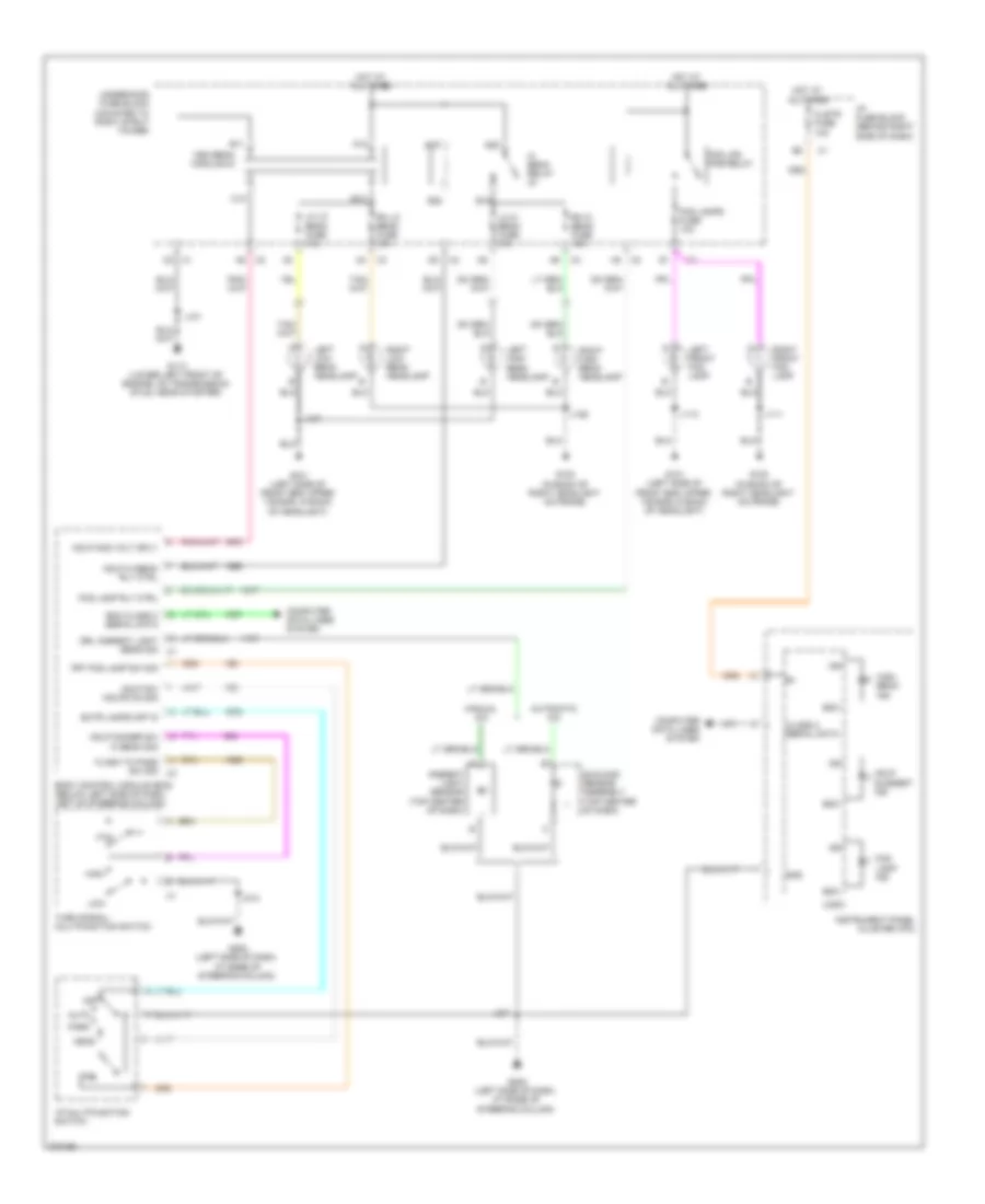 https://portal-diagnostov.com/license.html
Automotive Electricians Portal FZCO
Automotive Electricians Portal FZCO
https://portal-diagnostov.com/license.html
https://portal-diagnostov.com/license.html
Automotive Electricians Portal FZCO
Automotive Electricians Portal FZCOList of elements for 5.3L VIN C, Headlights Wiring Diagram for Buick Allure Super 2008:
- A12
- A5 x2
- Ambient light sensor (top center of dash)
- Auto
- Automatic a/c
- B11
- B12
- Bcm
- Bcm class 2 serial data
- Body control module (bcm) (below left side of dash, left of steering column)
- C12
- C2 x1
- Class 2 serial data
- Clstr fuse 10a
- Computer data lines system
- Drl ambient light sens sig x1
- E19
- E20
- Extr lamps off in
- Flash to pass sw sig x3
- Fog
- Fog lamp ind
- Fog lamp rly ctrl
- Fog lamps fuse 10a
- Fog lps pcb relay
- Frt fog lamp sw sig
- Ftp
- G100 (in back of right headlight on frame)
- G101 (left side of front end upper tie bar, in back of headlight)
- G113 (lower left front of engine, on transmission stud, near starter)
- G19
- G20
- G202 (left side of dash, at base of steering column)
- Gnd
- Hdlp dimmer sw hi beam sig
- Hdlp hi beam rly ctrl
- Hdlp mod volt sply
- Hdlp suggest ind
- Hdlp sw hdlps on sig
- Hdm beam module 35
- Head
- Hi beam relay
- High
- High beam ind
- Hot at all times
- I/p fuse block (behind right side of dash)
- I/p multifunction switch
- Ign
- Instrument panel cluster (ipc)
- J101
- J111
- J113
- J126
- J127
- J211
- J214
- Left front fog lamp
- Left high beam headlamp
- Left low beam headlamp
- Lh hi beam fuse 10a
- Lh lo beam fuse 10a
- Logic
- Low
- Manual a/c
- Off
- Park
- Rh hi beam fuse 10a
- Rh lo beam fuse 10a
- Right front fog lamp
- Right high beam headlamp
- Right low beam headlamp
- Sunload sensor assembly (top center of dash)
- Turn signal/ multifunction switch
- Underhood fuse block (mounted to right strut tower)
HORN
Horn Wiring Diagram for Buick Allure Super 2008
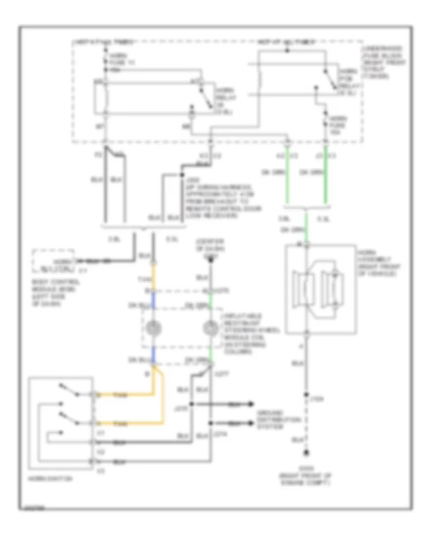 https://portal-diagnostov.com/license.html
Automotive Electricians Portal FZCO
Automotive Electricians Portal FZCO
https://portal-diagnostov.com/license.html
https://portal-diagnostov.com/license.html
Automotive Electricians Portal FZCO
Automotive Electricians Portal FZCOList of elements for Horn Wiring Diagram for Buick Allure Super 2008:
- (center of dash) g201
- 3.8l
- 5.3l
- A2 x3
- Body control module (bcm) (left side of dash)
- G100 (right front of engine compt)
- Ground distribution system
- Horn assembly (right front of vehicle)
- Horn fuse 11 15a
- Horn fuse 15a
- Horn pcb relay (5.3l)
- Horn relay (3.8l)
- Horn rly ctrl
- Horn switch
- Hot at all times
- Inflatable restraint steering wheel module coil (in steering column)
- J124
- J215
- K3 x2
- Tan
- Underhood fuse block (right front strut tower)
- X275 c
- X277
- X3 j3
INSTRUMENT CLUSTER
Instrument Cluster Wiring Diagram, with Message Center (1 of 2) for Buick Allure Super 2008
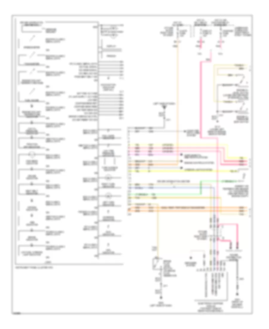 https://portal-diagnostov.com/license.html
Automotive Electricians Portal FZCO
Automotive Electricians Portal FZCO
https://portal-diagnostov.com/license.html
https://portal-diagnostov.com/license.html
Automotive Electricians Portal FZCO
Automotive Electricians Portal FZCOList of elements for Instrument Cluster Wiring Diagram, with Message Center (1 of 2) for Buick Allure Super 2008:
- (cool temp, trip odom & tachometer)
- (left side of dash) g202
- (uplevel)
- 3.8l
- 5.3l
- Abs indicator
- Abs/tcs class 2 serial data
- Air bag indicator
- Air temp sens sig
- Ambient air temperature sensor (w/ tachometer) (center front of engine compt)
- B10
- Bat pos voltage
- Bcm class 2 serial data
- Brake fluid level switch (on brake fluid reservoir)
- Brake indicator
- Brake warning ind ctrl
- Charging indicator
- Clstr fuse 10a
- Compass fuse 10a
- Compass sens feed
- Compass sens ret
- Computer data lines system
- Cruise indicator
- Defogger system
- Dic fuel signal
- Dic gage signal
- Dic menu sw sig
- Dic odo sig
- Dic set/reset sw sig
- Display
- Display fuse 18 10a
- Driver information center
- Driver information center (dic)
- Ecm/pcm class 2 serial data
- Electronic compass module (top right side of rear package shelf)
- Engine controls system
- Engine coolant temperature gage
- Engine coolant temperature indicator
- Engine oil level switch (lower center front of engine oil pan)
- Engine oil pressure (eop) switch
- Fog lamps indicator
- Fuel gauge
- G113 (lower left rear of engine, near starter)
- G202 (left side of dash)
- G301 (front of driver's door sill)
- Gnd
- High beam indicator
- Hot at all times
- Hot w/ ign 1 relay energized
- Hot w/ ign main pcb relay energized
- I/p fuse block (right side of dash)
- Ign
- Ign 1 voltage
- Instrument panel cluster (ipc)
- Interior lights system
- Ipc class 2 serial data
- Ipc/bcm class 2 serial data
- J211
- J303
- Km/h indicator
- Left turn indicator
- Logic
- Low fuel warning lamp indicator
- Low oil pressure indicator
- Low ref
- Low tire pressure indicator
- Malfunction indicator lamp (mil)
- Message request
- Mph indicator
- Pass seat belt ind
- Pcm/ecm class 2 serial data
- Pnk
- Pnk d11
- Power distribution system
- Prnd321
- Rear defog rly ctrl
- Red
- Right turn indicator
- Sdm class 2 serial data
- Seat belt indicator
- Speedometer
- Tachometer
- Tan
- Traction off indicator
- Turn audible indicator
- Underhood fuse block (right front strut tower)
Instrument Cluster Wiring Diagram, with Message Center (2 of 2) for Buick Allure Super 2008
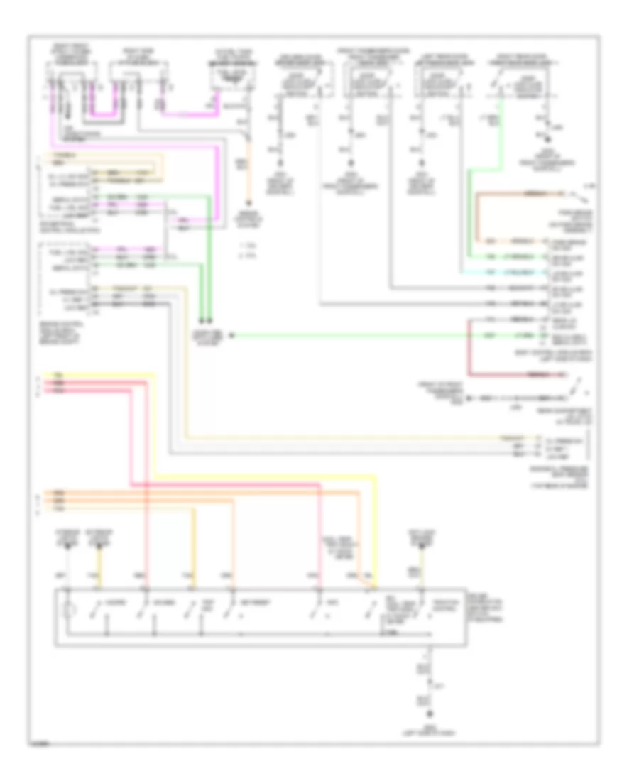 https://portal-diagnostov.com/license.html
Automotive Electricians Portal FZCO
Automotive Electricians Portal FZCO
https://portal-diagnostov.com/license.html
https://portal-diagnostov.com/license.html
Automotive Electricians Portal FZCO
Automotive Electricians Portal FZCOList of elements for Instrument Cluster Wiring Diagram, with Message Center (2 of 2) for Buick Allure Super 2008:
- (driver's door) driver door lock
- (front of front passenger's door sill) g302
- (front passenger's door) front passenger door lock
- (in fuel tank) fuel pump & sender assembly
- (left rear door) left rear door lock
- (right front strut tower) underhood fuse block
- (right rear door) right rear door lock
- (right side of dash) i/p fuse block
- 3.8l
- 5 v ref 1
- 5.3l
- 5v ref 1
- A12
- Air conditioning system
- Anti-lock brakes system
- B12
- Bcm class 2 serial data x1
- Body control module (bcm) (left side of dash)
- Computer data lines system
- Cool temp, trip odom & tacho- meter
- Door lock ajar indicator switch
- Driver information center (dic) switch (if equipped)
- E/m cool temp, trip odom & tacho- meter
- Engine control module (ecm) (left front of engine compt)
- Engine controls system
- Engine oil pressure (eop) sensor (5.3l) (top rear of engine)
- Exterior lights system
- Fuel
- Fuel level sensor
- Fuel lvel sig
- G202 (left side of dash)
- G301 (front of driver's door sill)
- G302 (front of front passenger's door sill)
- Gauges
- Hazard
- Info
- Interior lights system
- J211
- J303
- J406
- J500
- J604
- Lf dr ajar sw sig
- Low ref
- Lr dr ajar sw sig
- Oil lvl sw sig
- Oil press sw
- Park brake sw sig
- Park brake switch (on park brake assembly)
- Pnk
- Powertrain control module (pcm)
- Rear compartment lid latch (in trunk lid)
- Rear lid ajar sw x2
- Red
- Rf dr ajar sw sig
- Rr dr ajar sw sig
- Serial data
- Set/reset
- Tan
- Traction control
- Trip odo
Instrument Cluster Wiring Diagram, without Message Center (1 of 2) for Buick Allure Super 2008
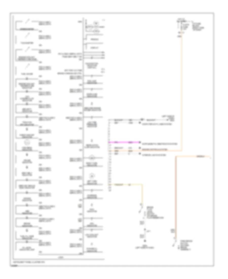 https://portal-diagnostov.com/license.html
Automotive Electricians Portal FZCO
Automotive Electricians Portal FZCO
https://portal-diagnostov.com/license.html
https://portal-diagnostov.com/license.html
Automotive Electricians Portal FZCO
Automotive Electricians Portal FZCOList of elements for Instrument Cluster Wiring Diagram, without Message Center (1 of 2) for Buick Allure Super 2008:
- (left side of dash) g202
- Abs indicator
- Abs/tcs class 2 serial data
- Air bag indicator
- Bat pos voltage
- Bcm class 2 serial data
- Brake fluid level switch (on brake fluid reservoir)
- Brake indicator
- Brake warning ind ctrl
- Change oil indicator
- Charging indicator
- Check gas cap indicator
- Clstr fuse 10a
- Computer data lines system
- Cruise indicator
- Display
- Door ajar indicator
- E8 x1
- Engine controls system
- Engine coolant temperature gage
- Engine coolant temperature indicator
- Fog lamp indicator
- Fuel fill side indicator
- Fuel gauge
- G202 (left side of dash)
- Gnd
- High beam indicator
- Hot at all times
- I/p fuse block (right side of dash)
- Ign
- Ign pcm class 2 serial data
- Instrument panel cluster (ipc)
- Interior lights system
- Ipc class 2 serial data
- Ipc/bcm class 2 serial data
- J211
- Km/h indicator
- Left turn indicator
- Logic
- Low coolant indicator
- Low ref
- Low tire pressure indicator
- Low washer fluid indicator
- Malfunction indicator lamp (mil)
- Mph indicator
- Oil level indicator lamp
- Park brake switch (on park brake assembly)
- Pass seat belt ind
- Pcm class 2 serial data
- Prnd321
- Rear hatch ajar indicator
- Reduced engine power indicator
- Right turn indicator
- Sdm class 2 serial data
- Seat belt indicator
- Security indicator
- Service vehicle soon indicator
- Speedometer
- Tachometer
- Traction off indicator
Instrument Cluster Wiring Diagram, without Message Center (2 of 2) for Buick Allure Super 2008
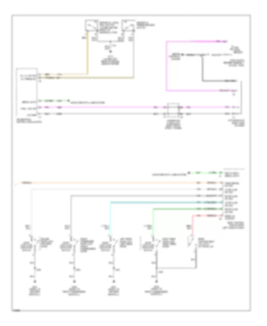 https://portal-diagnostov.com/license.html
Automotive Electricians Portal FZCO
Automotive Electricians Portal FZCO
https://portal-diagnostov.com/license.html
https://portal-diagnostov.com/license.html
Automotive Electricians Portal FZCO
Automotive Electricians Portal FZCOList of elements for Instrument Cluster Wiring Diagram, without Message Center (2 of 2) for Buick Allure Super 2008:
- A12
- B12
- Bcm class 2 serial data
- Body control module (bcm) (left side of dash)
- Computer data lines system
- Door lock ajar indicator switch
- Driver door lock (driver's door)
- Engine controls system
- Engine oil level (eol) switch (lower center front of engine oil pan)
- Engine oil pressure (eop) switch
- Front passenger door lock (front passenger's door)
- Fuel level sensor
- Fuel lvel sig
- Fuel pump & sender assembly (in fuel tank)
- G113 (lower left rear of engine, near starter)
- G301 (front of driver's door sill)
- G302 (front of front passenger's door sill)
- I/p fuse block (right side of dash)
- J303
- J406
- J500
- J604
- Left rear door lock (left rear door)
- Lf dr ajar sw sig
- Low ref
- Lr dr ajar sw sig
- Oil lvl sw sig
- Oil press sw
- Park brake sw sig
- Powertrain control module (pcm)
- Rear compartment lid latch (in trunk lid)
- Rear lid ajar sw
- Rf dr ajar sw sig
- Right rear door lock (right rear door)
- Rr dr ajar sw sig
- Serial data
- Underhood fuse block (right front strut tower)
INTERIOR LIGHTS
Courtesy Lamps Wiring Diagram for Buick Allure Super 2008
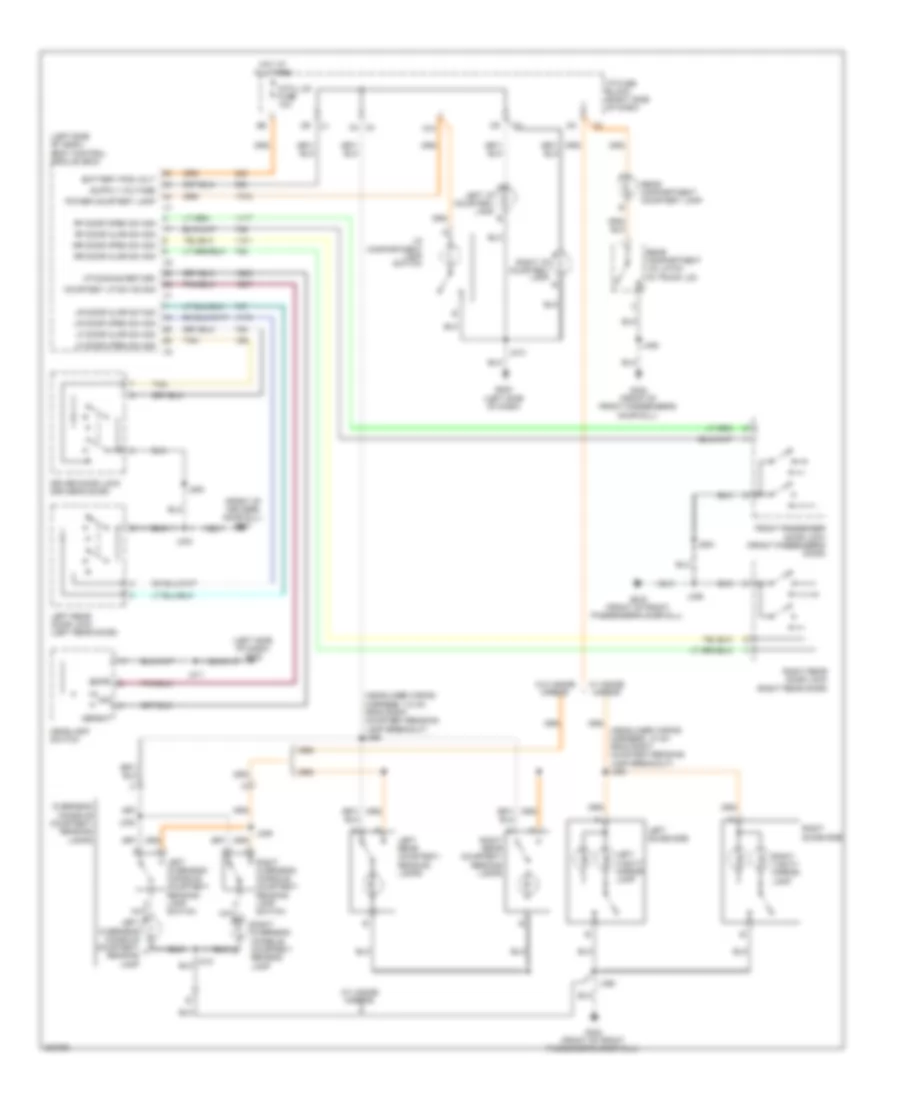 https://portal-diagnostov.com/license.html
Automotive Electricians Portal FZCO
Automotive Electricians Portal FZCO
https://portal-diagnostov.com/license.html
https://portal-diagnostov.com/license.html
Automotive Electricians Portal FZCO
Automotive Electricians Portal FZCOList of elements for Courtesy Lamps Wiring Diagram for Buick Allure Super 2008:
- (front of driver's door sill) g301
- (headliner wiring harness, 10 cm from right courtesy/reading lamp breakout) j393
- (headliner wiring harness, 7.5 cm from right courtesy/reading lamp breakout) j398
- (left side of dash) body control module (bcm)
- (left side of dash) g202
- (w/ inside mirror)
- Battery pos volt
- Courtesy lp sw on sig
- D10
- Defeat
- Dome
- Driver door lock (driver's door)
- Front passenger door lock (front passenger's door)
- G200 (left side of dash)
- G302 (front of front passenger's door sill)
- Headlamp switch
- Hot at all times
- I/p compartment lamp switch
- I/p dimming return
- I/p fuse block (right side of dash)
- Int/illum fuse 10a
- J211
- J213
- J303
- J308
- J309
- J390
- J406
- J500
- J604
- Left i/p courtesy lamp
- Left overhead console courtesy/ reading lamp
- Left overhead console courtesy/ reading lamp switch
- Left rear courtesy/ reading lamps
- Left rear door lock (left rear door)
- Left sunshade
- Left vanity mirror lamp
- Lf door ajar sw sig
- Lf door open sw sig
- Lr door ajar sw sig
- Lr door open sw sig
- Off
- Overhead console courtesy/ reading lamps
- Power courtesy lamp
- Rear compartment courtesy lamp
- Rear compartment lid latch (in trunk lid)
- Rf door ajar sw sig
- Rf door open sw sig
- Right i/p courtesy lamp
- Right overhead console courtesy/ reading lamp
- Right overhead console courtesy/ reading lamp switch
- Right rear courtesy/ reading lamps
- Right rear door lock (right rear door)
- Right sunshade
- Right vanity mirror lamp
- Rr door ajar sw sig
- Rr door open sw sig
- Tan
- W/ inside mirror
- W/o inside mirror
- X2 c4
Instrument Illumination Wiring Diagram for Buick Allure Super 2008
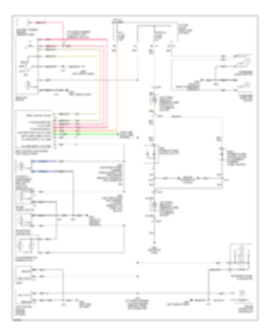 https://portal-diagnostov.com/license.html
Automotive Electricians Portal FZCO
Automotive Electricians Portal FZCO
https://portal-diagnostov.com/license.html
https://portal-diagnostov.com/license.html
Automotive Electricians Portal FZCO
Automotive Electricians Portal FZCOList of elements for Instrument Illumination Wiring Diagram for Buick Allure Super 2008:
- (i/p wiring harness, 21 cm from lamp assembly switch)
- 10 volt ref
- Auto
- Automatic transmission shift lever position indicator (console shift)
- Battery current sensor (near battery)
- Battery positive voltage
- Bcm class 2 serial data
- Body control module (bcm) (left side of dash)
- C x275
- Computer data lines system
- Driver door lock switch
- Driver information center (dic)
- Driver window switch
- F x275
- G200 (left side of dash)
- G201 (center of dash)
- G202 (left side of dash)
- G301 (front of driver's door sill)
- G302 (front of front passenger's door sill)
- Ground
- Ground distribution system
- Head
- Headlamp switch
- Hot at all times
- Hvac control module (center of dash)
- I/p dimming return
- I/p dimming signal
- I/p fuse block (right side of dash)
- Illum
- Inflatable restraint steering wheel module coil (in steering column)
- Instrument panel cluster (ipc)
- Int/ illum fuse 10a
- J203 (i/p wiring harness, 4 cm from second breakout from dlc connector)
- J204
- J211
- J213
- J214
- J215
- J280 (instrument panel harness, approximately 4 cm from second breakout from data link connector)
- J303
- J501
- J502 (left front door trim harness, 5 cm from breakout to door lock switch)
- J605
- Left steering wheel control switch
- Off
- Outside rearview mirror switch
- Park
- Park lamp sw on sig
- Passenger door lock switch
- Passenger window switch
- Pnk
- Radio
- Right steering wheel control switch (w/ accessory steering wheel control)
- Sply volt
- Str/whl/ illum fuse 2a
- X277
NAVIGATION
Navigation Wiring Diagram for Buick Allure Super 2008
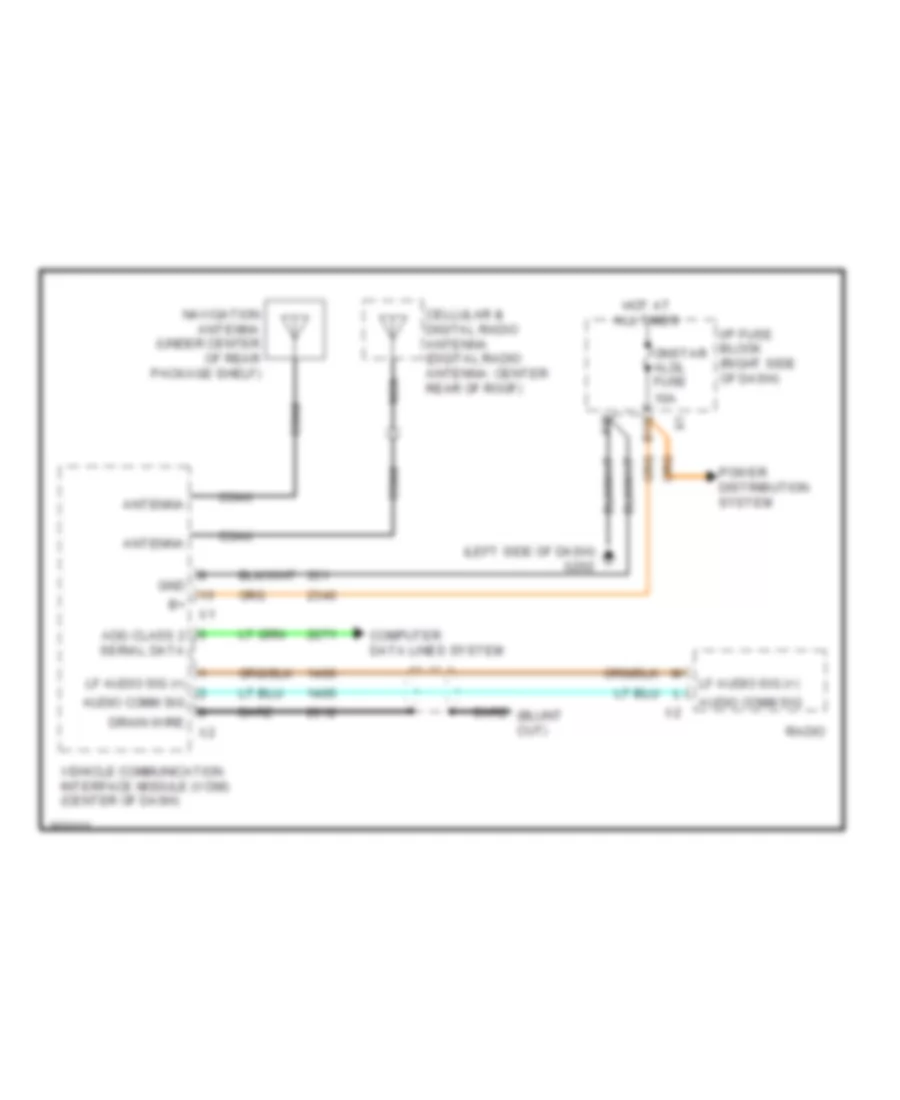 https://portal-diagnostov.com/license.html
Automotive Electricians Portal FZCO
Automotive Electricians Portal FZCO
https://portal-diagnostov.com/license.html
https://portal-diagnostov.com/license.html
Automotive Electricians Portal FZCO
Automotive Electricians Portal FZCOList of elements for Navigation Wiring Diagram for Buick Allure Super 2008:
- (left side of dash) g202
- 10a
- Adg class 2 serial data
- Antenna
- Audio comm sig
- B10
- Bare
- Cellular & digital radio antenna (digital radio antenna: center rear of roof)
- Coax
- Computer data lines system
- Drain wire
- Gnd
- Hot at all times
- I/p fuse block (right side of dash)
- Lf audio sig (+)
- Lf audio sig (+)
- Navigation antenna (under center of rear package shelf)
- Nca
- Onstar aldl fuse
- Power distribution system
- Radio
- Vehicle communication interface module (vcim) (center of dash)
Parking Assistant Wiring Diagram for Buick Allure Super 2008
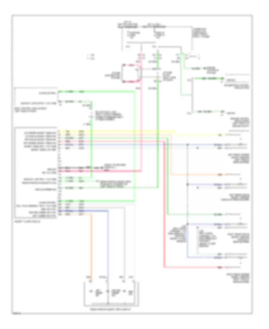 https://portal-diagnostov.com/license.html
Automotive Electricians Portal FZCO
Automotive Electricians Portal FZCO
https://portal-diagnostov.com/license.html
https://portal-diagnostov.com/license.html
Automotive Electricians Portal FZCO
Automotive Electricians Portal FZCOList of elements for Parking Assistant Wiring Diagram for Buick Allure Super 2008:
- (front of driver's door sill) g301
- 3.8l
- 5.3l
- A rear parking assist (rpa) diagnostic connector (left side of trunk)
- A9 x2
- Backup lamp sply voltage
- Body control module (bcm) (left side of dash)
- Center amber ind
- Center amber ind ctrl
- Chime control
- Compass fuse 10a
- D11
- Display fuse 18 10a
- Engine control module (ecm) (left front of engine compt)
- Engine controls system
- F11
- Ground
- H1 x2
- Hot w/ ign 1 relay 37 energized
- Hot w/ ignition main pcb relay energized
- I/p fuse block (right side of dash)
- Ign voltage
- J2 x4
- J303
- J450 (rpa wiring harness, 7 cm from breakout for right object alarm sensor)
- J451 (rpa wiring harness, 7 cm from breakout for right object alarm sensor)
- Left amber ind
- Left amber ind ctrl
- Left rear corner object sensor (left side of rear bumper)
- Left rear middle object sensor (middle of rear bumper)
- Lr corner object sens sig
- Lr middle object sens sig
- Object alarm module
- Object sens low ref
- Object sens sply voltage
- Pnk
- Power distribution system
- Powertrain control module (pcm)
- Rear parking assist (rpa) display
- Rear parking diagnostic sig
- Red
- Red ind
- Red ind ctrl
- Right rear corner object sensor (right side of rear bumper)
- Right rear middle object sensor (middle of rear bumper)
- Rr corner object sens sig
- Rr middle object sens sig
- Splice pack jx307 (body wiring harness, under passenger seat, at rear carpet)
- Telltale assembly sply voltage
- Underhood fuse block (right front strut tower)
- Vehicle speed sig
- Vss sig
- X1 e10
- X2 b11
- X2 e3
POWER DISTRIBUTION
3.6L VIN 7
3.6L VIN 7, Power Distribution Wiring Diagram (1 of 4) for Buick Allure Super 2008
 https://portal-diagnostov.com/license.html
Automotive Electricians Portal FZCO
Automotive Electricians Portal FZCO
https://portal-diagnostov.com/license.html
https://portal-diagnostov.com/license.html
Automotive Electricians Portal FZCO
Automotive Electricians Portal FZCOList of elements for 3.6L VIN 7, Power Distribution Wiring Diagram (1 of 4) for Buick Allure Super 2008:
- (mounted to right strut tower) underhood fuse block
- 3.6l
- 3.8l
- A1 x1
- Abs mtr fuse 31 40a
- Abs sol fuse 19 25a
- Air pump fuse 25 50a
- Audio amplifier (w/ 9 speaker system)
- Automatic a/c
- B10
- Batt main 1 fuse 26 40a
- Batt main 2 fuse 27 50a
- Batt main 3 fuse 28 40a
- Batt main 4 fuse 30 30a
- Battery
- Blower motor control module
- Body control module (bcm)
- C10
- Canister fuse 10a
- Chmsl/ bkup fuse 15a
- Clstr fuse 10a
- D10
- Data link connector (dlc)
- Digital radio receiver
- Dr/lck trunk fuse 15a
- Driver heated seat relay (if equipped)
- Driver seat adjuster switch
- Driver seat lumbar switch
- Driver window switch
- E x2
- E12
- Electronic brake control module (ebcm) (w/ abs)
- Engine control module (ecm)
- Evaporative emission (evap) canister vent solenoid valve
- F10
- Generator
- Hazrd fuse 20a
- Htd/ seat fuse 20a
- Hvac control module
- Hvac fuse 10a
- I/p fuse block (behind right side of dash)
- Inflatable restraint front passenger presence system (pps) module
- Inside rearview mirror
- Instrument panel cluster (ipc)
- Int/ illum fuse 10a
- J331
- J595
- Manual a/c
- Onstar/ aldl fuse 10a
- Outside rear view mirror switch
- Park switch (floor console front compartment)
- Passenger heated seat relay (if equipped)
- Passenger seat adjuster switch (if equipped)
- Passenger window switch
- Pcm/ etc fuse 16 15a
- Power lumbar control seat
- Powertrain control module (pcm)
- Prk/ lamp relay
- Prk/ switch fuse 5a
- Prk/lamp fuse 10a
- Pwr/ mir fuse 10a
- Pwr/ seat circuit breaker 25a
- Pwr/wndw circuit breaker 25a
- R/ defog relay
- Radio
- Rap relay
- Rdo/ amp fuse 25a
- Red
- Remote control door lock receiver (rcdlr)
- Rfa/ mod fuse 10a
- S/roof fuse 20a
- Secondary air injection (air) pump relay (w/ california pzev emission system)
- Starter
- Sunroof motor/ actuator
- To tcm fuse 8 (diagram 2 of 4)
- Vehicle communication interface module (vcim) (w/ onstar)
- W/ digital audio system
- W/ driver
- W/ sunroof
- W/o digital audio system
- W/o driver
- W/o sunroof
- Washer/ rvc fuse 6 15a
- X1 d12
- X2 d9
- X2 e2
- X2 f9
- X4 c2
3.6L VIN 7, Power Distribution Wiring Diagram (2 of 4) for Buick Allure Super 2008
 https://portal-diagnostov.com/license.html
Automotive Electricians Portal FZCO
Automotive Electricians Portal FZCO
https://portal-diagnostov.com/license.html
https://portal-diagnostov.com/license.html
Automotive Electricians Portal FZCO
Automotive Electricians Portal FZCOList of elements for 3.6L VIN 7, Power Distribution Wiring Diagram (2 of 4) for Buick Allure Super 2008:
- (3.6l) j116
- (3.8l) j101
- (behind left side of dash knee bolster, at base of steering column) g200
- (in automatic transmission wiring harness, inside transmission housing, 19 cm from inline connector x113) j115
- (in steering column wiring harness, near ignition switch) j200
- 1-2 shift solenoid valve
- 12 volt reference
- 2-3 shift solenoid valve
- 3.6l
- 3.8l
- A/c clutch fuse 13 10a
- A/c comp relay 38
- A10
- A11
- A2 x1
- Abs fuse 23 10a
- Acc
- Automatic a/c
- Automatic transmission
- Aux pwr fuse 10 25a
- Auxiliary power outlet
- Body control module
- Body control module (bcm)
- Cigar lighter
- Crank relay
- Crank voltage
- Cruise fuse 2a
- D11
- Display fuse 18 10a
- E12
- Electronic brake control module (w/ abs)
- Electronic compass module (w/ driver information center display)
- Engine control module (ecm)
- F12
- From ign 1 relay 37 (diagram 2 of 4)
- From washer/rvc a fuse 6 (diagram 1 of 4)
- G113 (3.8l) (lower left front of engine, on transmission stud, near starter)
- G115 (3.6l) (mounted to bank 1 cylinder head, above exhaust manifold)
- G202 (left side of dash, at base of steering column)
- G302 (in right door sill, forward of right front seat)
- Hvac control module
- I/p fuse block (behind right side of dash)
- Ign 1 relay 37
- Ignition 1 voltage
- Ignition 3 voltage
- Ignition switch
- Inflatable restraint front passenger presence system module
- Inflatable restraint passenger air bag on/off indicator
- Inflatable restraint sensing & diagnostic module
- Inflatable restraint steering wheel module coil
- Inside air temperature sensor
- J213
- J214
- J406
- Key in ignition switch
- Key in ignition switch signal
- Left steering wheel control switch
- Lock
- Manual a/c
- Nca
- P/train relay 40
- Pcm fuse 15 10a
- Pnk
- Powertrain control module (pcm)
- Rear object sensor control module
- Red
- Run
- Sir fuse 9 10a
- Start
- Steering angle sensor (w/ abs)
- Tcm fuse 8 15a
- To a/c clutch fuse (diagram 2 of 4)
- To etc fuse 17 (diagram 3 of 4)
- To fan 2 fuse 32 (diagram 3 of 4)
- Torque converter clutch (tcc) solenoid valve
- Trans sol fuse 21 10a
- Transmission control module (tcm)
- Transmission control module (tcm) (3.6l)
- Underhood fuse block (mounted to right strut tower)
- W/ park assist
- X1 a5
- X1 b3
- X1 b4
- X100
- X2 a12
- X2 b9
- Yaw & lateral acceleration sensor (w/ abs)
3.6L VIN 7, Power Distribution Wiring Diagram (3 of 4) for Buick Allure Super 2008
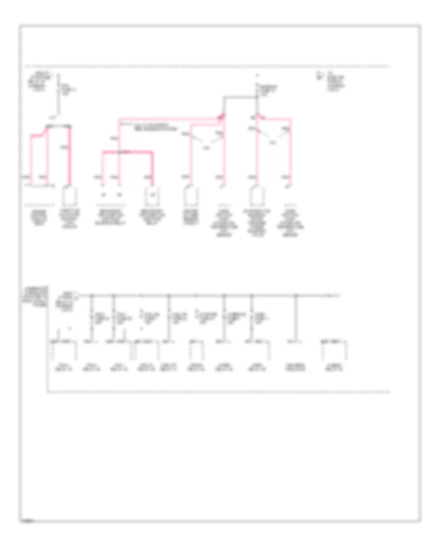 https://portal-diagnostov.com/license.html
Automotive Electricians Portal FZCO
Automotive Electricians Portal FZCO
https://portal-diagnostov.com/license.html
https://portal-diagnostov.com/license.html
Automotive Electricians Portal FZCO
Automotive Electricians Portal FZCOList of elements for 3.6L VIN 7, Power Distribution Wiring Diagram (3 of 4) for Buick Allure Super 2008:
- 3.6l
- 3.8l
- 3.8l w/ california pzev emission system
- A11
- A18
- A19
- C10
- C11
- Crank relay 48
- E14
- Emission fuse 12 10a
- Engine control module (ecm)
- Etc fuse 17 15a
- Evaporative emission (evap) canister purge solenoid valve
- Fan 1 fuse 29 30a
- Fan 1 relay 42
- Fan 2 fuse 32 30a
- Fan 2 relay 46
- Fan 3 relay 43
- Fog lp relay 36
- Fog lps fuse 7 15a
- From p/train b relay 40 (diagram 2 of 4)
- From p/train d relay 40 (diagram 2 of 4)
- Fuel pp fuse 22 15a
- Fuel pp relay 41
- G19
- G20
- Hdm beam module 35
- Heated oxygen sensor (ho2s) 2
- Hi beam relay 34
- Horn fuse 11 15a
- Horn relay 39
- J117
- K15
- K18
- K19
- Mass air flow (maf)/ intake air temperature (iat) sensor
- Pnk
- Secondary air injection (air) pump relay
- Secondary air injection (air) pump solenoid relay
- Starter fuse 33 40a
- Throttle actuator control (tac) module
- To elek ign fuse 24 (diagram 4 of 4)
- Underhood fuse block (mounted to right strut tower)
- Wiper relay 45
- Wiper/ws fuse 5 25a
3.6L VIN 7, Power Distribution Wiring Diagram (4 of 4) for Buick Allure Super 2008
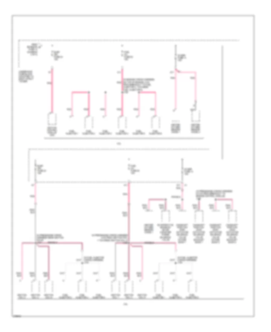 https://portal-diagnostov.com/license.html
Automotive Electricians Portal FZCO
Automotive Electricians Portal FZCO
https://portal-diagnostov.com/license.html
https://portal-diagnostov.com/license.html
Automotive Electricians Portal FZCO
Automotive Electricians Portal FZCOList of elements for 3.6L VIN 7, Power Distribution Wiring Diagram (4 of 4) for Buick Allure Super 2008:
- (in engine wiring harness, on top of engine, 8 cm pnk
- (in fuel injector wiring harness) j104
- (in fuel injector wiring harness) j108
- (in pre-engine wiring harness 5 cm from ignition coil 1 towards ignition coil 3) j106
- (in pre-engine wiring harness near ignition coils) j103
- (in pre-engine wiring harness, 5.5 cm from breakout to engine control module) j110
- 02 ssr fuse 14 15a
- 3.6l
- 3.8l
- A11
- Camshaft position (cmp) actuator solenoid valve exhaust bank 1
- Camshaft position (cmp) actuator solenoid valve exhaust bank 2
- Camshaft position (cmp) actuator solenoid valve intake bank 1
- Camshaft position (cmp) actuator solenoid valve intake bank 2
- D11
- Elek ign fuse 24 15a
- Evaporative emission (evap) canister purge solenoid valve
- From breakout to fuel injector 3, towards fuel injector 5) j109
- From emission e fuse 12 (diagram 3 of 4)
- Fuel inj fuse 20 15a
- Fuel injector 1
- Fuel injector 2
- Fuel injector 3
- Fuel injector 4
- Fuel injector 5
- Fuel injector 6
- Heated oxygen sensor (ho2s) 1
- Heated oxygen sensor (ho2s) 2
- Ignition coil 1
- Ignition coil 2
- Ignition coil 3
- Ignition coil 4
- Ignition coil 5
- Ignition coil 6
- Ignition control module (icm)
- Nca
- Pnk
- Underhood fuse block (mounted to right strut tower)
3.8L VIN 2
3.8L VIN 2, Power Distribution Wiring Diagram (1 of 4) for Buick Allure Super 2008
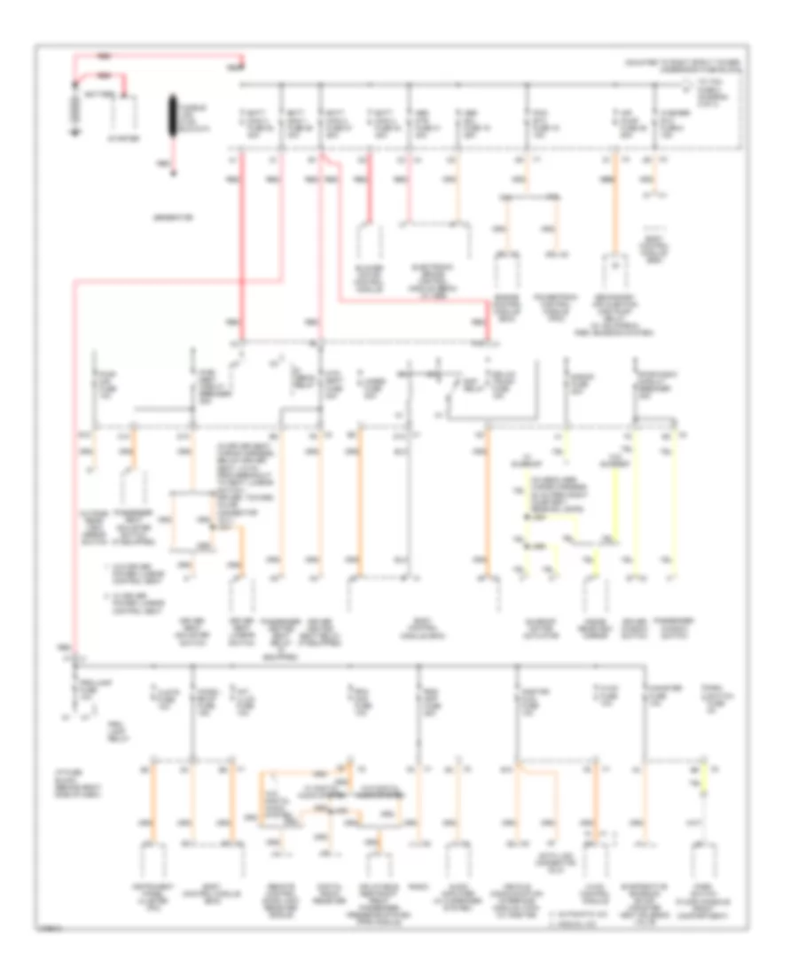 https://portal-diagnostov.com/license.html
Automotive Electricians Portal FZCO
Automotive Electricians Portal FZCO
https://portal-diagnostov.com/license.html
https://portal-diagnostov.com/license.html
Automotive Electricians Portal FZCO
Automotive Electricians Portal FZCOList of elements for 3.8L VIN 2, Power Distribution Wiring Diagram (1 of 4) for Buick Allure Super 2008:
- (mounted to right strut tower) underhood fuse block
- 3.6l
- 3.8l
- A1 x1
- Abs mtr fuse 31 40a
- Abs sol fuse 19 25a
- Air pump fuse 25 50a
- Audio amplifier (w/ 9 speaker system)
- Automatic a/c
- B10
- Batt main 1 fuse 26 40a
- Batt main 2 fuse 27 50a
- Batt main 3 fuse 28 40a
- Batt main 4 fuse 30 30a
- Battery
- Blower motor control module
- Body control module (bcm)
- C10
- Canister fuse 10a
- Chmsl/ bkup fuse 15a
- Clstr fuse 10a
- D10
- Data link connector (dlc)
- Digital radio receiver
- Dr/lck trunk fuse 15a
- Driver heated seat relay (if equipped)
- Driver seat adjuster switch
- Driver seat lumbar switch
- Driver window switch
- E x2
- E12
- Electronic brake control module (ebcm) (w/ abs)
- Engine control module (ecm)
- Evaporative emission (evap) canister vent solenoid valve
- F10
- Generator
- Hazrd fuse 20a
- Htd/ seat fuse 20a
- Hvac control module
- Hvac fuse 10a
- I/p fuse block (behind right side of dash)
- Inflatable restraint front passenger presence system (pps) module
- Inside rearview mirror
- Instrument panel cluster (ipc)
- Int/ illum fuse 10a
- J331
- J595
- Manual a/c
- Onstar/ aldl fuse 10a
- Outside rear view mirror switch
- Park switch (floor console front compartment)
- Passenger heated seat relay (if equipped)
- Passenger seat adjuster switch (if equipped)
- Passenger window switch
- Pcm/ etc fuse 16 15a
- Power lumbar control seat
- Powertrain control module (pcm)
- Prk/ lamp relay
- Prk/ switch fuse 5a
- Prk/lamp fuse 10a
- Pwr/ mir fuse 10a
- Pwr/ seat circuit breaker 25a
- Pwr/wndw circuit breaker 25a
- R/ defog relay
- Radio
- Rap relay
- Rdo/ amp fuse 25a
- Red
- Remote control door lock receiver (rcdlr)
- Rfa/ mod fuse 10a
- S/roof fuse 20a
- Secondary air injection (air) pump relay (w/ california pzev emission system)
- Starter
- Sunroof motor/ actuator
- To tcm fuse 8 (diagram 2 of 4)
- Vehicle communication interface module (vcim) (w/ onstar)
- W/ digital audio system
- W/ driver
- W/ sunroof
- W/o digital audio system
- W/o driver
- W/o sunroof
- Washer/ rvc fuse 6 15a
- X1 d12
- X2 d9
- X2 e2
- X2 f9
- X4 c2
3.8L VIN 2, Power Distribution Wiring Diagram (2 of 4) for Buick Allure Super 2008
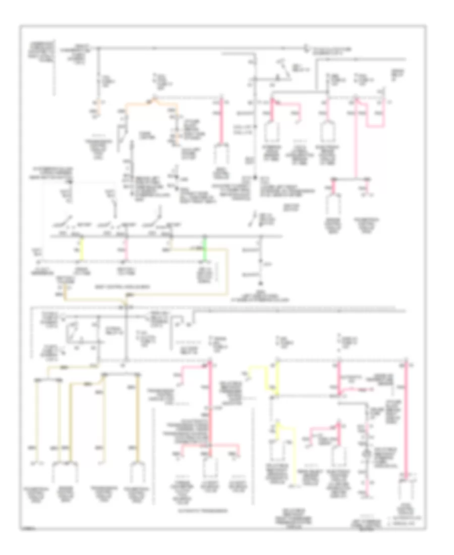 https://portal-diagnostov.com/license.html
Automotive Electricians Portal FZCO
Automotive Electricians Portal FZCO
https://portal-diagnostov.com/license.html
https://portal-diagnostov.com/license.html
Automotive Electricians Portal FZCO
Automotive Electricians Portal FZCOList of elements for 3.8L VIN 2, Power Distribution Wiring Diagram (2 of 4) for Buick Allure Super 2008:
- (3.6l) j116
- (3.8l) j101
- (behind left side of dash knee bolster, at base of steering column) g200
- (in automatic transmission wiring harness, inside transmission housing, 19 cm from inline connector x113) j115
- (in steering column wiring harness, near ignition switch) j200
- 1-2 shift solenoid valve
- 12 volt reference
- 2-3 shift solenoid valve
- 3.6l
- 3.8l
- A/c clutch fuse 13 10a
- A/c comp relay 38
- A10
- A11
- A2 x1
- Abs fuse 23 10a
- Acc
- Automatic a/c
- Automatic transmission
- Aux pwr fuse 10 25a
- Auxiliary power outlet
- Body control module
- Body control module (bcm)
- Cigar lighter
- Crank relay
- Crank voltage
- Cruise fuse 2a
- D11
- Display fuse 18 10a
- E12
- Electronic brake control module (w/ abs)
- Electronic compass module (w/ driver information center display)
- Engine control module (ecm)
- F12
- From ign 1 relay 37 (diagram 2 of 4)
- From washer/rvc a fuse 6 (diagram 1 of 4)
- G113 (3.8l) (lower left front of engine, on transmission stud, near starter)
- G115 (3.6l) (mounted to bank 1 cylinder head, above exhaust manifold)
- G202 (left side of dash, at base of steering column)
- G302 (in right door sill, forward of right front seat)
- Hvac control module
- I/p fuse block (behind right side of dash)
- Ign 1 relay 37
- Ignition 1 voltage
- Ignition 3 voltage
- Ignition switch
- Inflatable restraint front passenger presence system module
- Inflatable restraint passenger air bag on/off indicator
- Inflatable restraint sensing & diagnostic module
- Inflatable restraint steering wheel module coil
- Inside air temperature sensor
- J213
- J214
- J406
- Key in ignition switch
- Key in ignition switch signal
- Left steering wheel control switch
- Lock
- Manual a/c
- Nca
- P/train relay 40
- Pcm fuse 15 10a
- Pnk
- Powertrain control module (pcm)
- Rear object sensor control module
- Red
- Run
- Sir fuse 9 10a
- Start
- Steering angle sensor (w/ abs)
- Tcm fuse 8 15a
- To a/c clutch fuse (diagram 2 of 4)
- To etc fuse 17 (diagram 3 of 4)
- To fan 2 fuse 32 (diagram 3 of 4)
- Torque converter clutch (tcc) solenoid valve
- Trans sol fuse 21 10a
- Transmission control module (tcm)
- Transmission control module (tcm) (3.6l)
- Underhood fuse block (mounted to right strut tower)
- W/ park assist
- X1 a5
- X1 b3
- X1 b4
- X100
- X2 a12
- X2 b9
- Yaw & lateral acceleration sensor (w/ abs)
3.8L VIN 2, Power Distribution Wiring Diagram (3 of 4) for Buick Allure Super 2008
 https://portal-diagnostov.com/license.html
Automotive Electricians Portal FZCO
Automotive Electricians Portal FZCO
https://portal-diagnostov.com/license.html
https://portal-diagnostov.com/license.html
Automotive Electricians Portal FZCO
Automotive Electricians Portal FZCOList of elements for 3.8L VIN 2, Power Distribution Wiring Diagram (3 of 4) for Buick Allure Super 2008:
- 3.6l
- 3.8l
- 3.8l w/ california pzev emission system
- A11
- A18
- A19
- C10
- C11
- Crank relay 48
- E14
- Emission fuse 12 10a
- Engine control module (ecm)
- Etc fuse 17 15a
- Evaporative emission (evap) canister purge solenoid valve
- Fan 1 fuse 29 30a
- Fan 1 relay 42
- Fan 2 fuse 32 30a
- Fan 2 relay 46
- Fan 3 relay 43
- Fog lp relay 36
- Fog lps fuse 7 15a
- From p/train b relay 40 (diagram 2 of 4)
- From p/train d relay 40 (diagram 2 of 4)
- Fuel pp fuse 22 15a
- Fuel pp relay 41
- G19
- G20
- Hdm beam module 35
- Heated oxygen sensor (ho2s) 2
- Hi beam relay 34
- Horn fuse 11 15a
- Horn relay 39
- J117
- K15
- K18
- K19
- Mass air flow (maf)/ intake air temperature (iat) sensor
- Pnk
- Secondary air injection (air) pump relay
- Secondary air injection (air) pump solenoid relay
- Starter fuse 33 40a
- Throttle actuator control (tac) module
- To elek ign fuse 24 (diagram 4 of 4)
- Underhood fuse block (mounted to right strut tower)
- Wiper relay 45
- Wiper/ws fuse 5 25a
3.8L VIN 2, Power Distribution Wiring Diagram (4 of 4) for Buick Allure Super 2008
 https://portal-diagnostov.com/license.html
Automotive Electricians Portal FZCO
Automotive Electricians Portal FZCO
https://portal-diagnostov.com/license.html
https://portal-diagnostov.com/license.html
Automotive Electricians Portal FZCO
Automotive Electricians Portal FZCOList of elements for 3.8L VIN 2, Power Distribution Wiring Diagram (4 of 4) for Buick Allure Super 2008:
- (in engine wiring harness, on top of engine, 8 cm pnk
- (in fuel injector wiring harness) j104
- (in fuel injector wiring harness) j108
- (in pre-engine wiring harness 5 cm from ignition coil 1 towards ignition coil 3) j106
- (in pre-engine wiring harness near ignition coils) j103
- (in pre-engine wiring harness, 5.5 cm from breakout to engine control module) j110
- 02 ssr fuse 14 15a
- 3.6l
- 3.8l
- A11
- Camshaft position (cmp) actuator solenoid valve exhaust bank 1
- Camshaft position (cmp) actuator solenoid valve exhaust bank 2
- Camshaft position (cmp) actuator solenoid valve intake bank 1
- Camshaft position (cmp) actuator solenoid valve intake bank 2
- D11
- Elek ign fuse 24 15a
- Evaporative emission (evap) canister purge solenoid valve
- From breakout to fuel injector 3, towards fuel injector 5) j109
- From emission e fuse 12 (diagram 3 of 4)
- Fuel inj fuse 20 15a
- Fuel injector 1
- Fuel injector 2
- Fuel injector 3
- Fuel injector 4
- Fuel injector 5
- Fuel injector 6
- Heated oxygen sensor (ho2s) 1
- Heated oxygen sensor (ho2s) 2
- Ignition coil 1
- Ignition coil 2
- Ignition coil 3
- Ignition coil 4
- Ignition coil 5
- Ignition coil 6
- Ignition control module (icm)
- Nca
- Pnk
- Underhood fuse block (mounted to right strut tower)
5.3L VIN C
5.3L VIN C, Power Distribution Wiring Diagram (1 of 3) for Buick Allure Super 2008
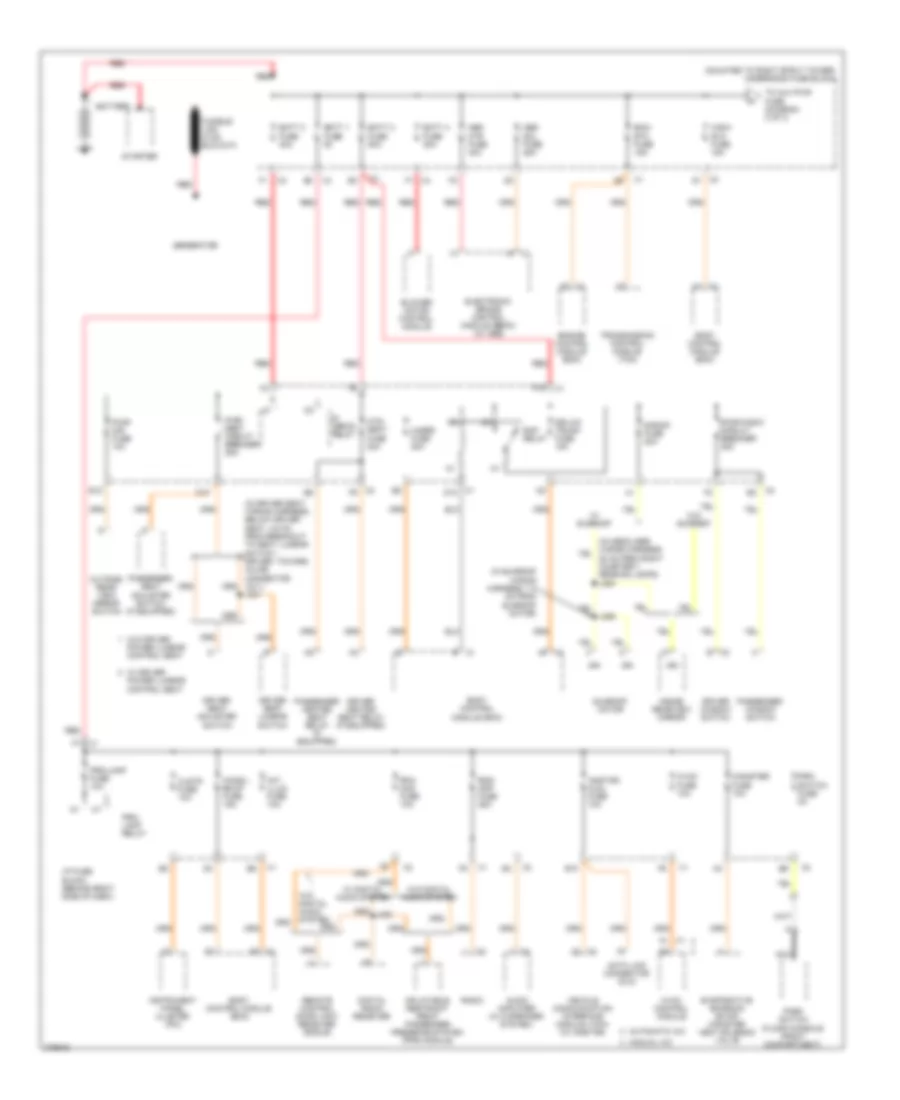 https://portal-diagnostov.com/license.html
Automotive Electricians Portal FZCO
Automotive Electricians Portal FZCO
https://portal-diagnostov.com/license.html
https://portal-diagnostov.com/license.html
Automotive Electricians Portal FZCO
Automotive Electricians Portal FZCOList of elements for 5.3L VIN C, Power Distribution Wiring Diagram (1 of 3) for Buick Allure Super 2008:
- (in sunroof wiring harness, 7.5 cm from sunroof motor)
- (mounted to right strut tower) underhood fuse block
- Abs mtr fuse 40a
- Abs sol fuse 25a
- Audio amplifier (w/ 9 speaker system)
- Automatic a/c
- B10
- Batt 1 fuse
- Batt 2 fuse 50a
- Batt 3 fuse 40a
- Batt 4 fuse 30a
- Battery
- Blower motor control module
- Body control module (bcm)
- Canister fuse 10a
- Chmsl/ bkup fuse 15a
- Clstr fuse 10a
- D10
- Data link connector (dlc)
- Digital radio receiver
- Dr/lck trunk fuse 15a
- Driver heated seat relay (if equipped)
- Driver seat adjuster switch
- Driver seat lumbar switch
- Driver window switch
- E x2
- E12
- Ecm/ etc fuse 15a
- Electronic brake control module (ebcm) (w/ abs)
- Engine control module (ecm)
- Evaporative emission (evap) canister vent solenoid valve
- F10
- Generator
- Hazrd fuse 20a
- Htd/ seat fuse 20a
- Hvac control module
- Hvac fuse 10a
- I/p fuse block (behind right side of dash)
- Ign
- Inflatable restraint front passenger presence system (pps) module
- Inside rearview mirror
- Instrument panel cluster (ipc)
- Int/ illum fuse 10a
- J331
- J395
- Manual a/c
- Nca
- Onstar/ aldl fuse 10a
- Outside rear view mirror switch
- Park switch (floor console front compartment)
- Passenger heated seat relay (if equipped)
- Passenger seat adjuster switch (if equipped)
- Passenger window switch
- Power lumbar control seat
- Prk/ lamp relay
- Prk/ switch fuse 5a
- Prk/lamp fuse 10a
- Pwr/ mir fuse 10a
- Pwr/ seat circuit breaker 25a
- Pwr/wndw circuit breaker 25a
- R/ defog relay
- Radio
- Rap relay
- Rdo/ amp fuse 25a
- Red
- Remote control door lock receiver (rcdlr)
- Rfa/ mod fuse 10a
- S/roof fuse 20a
- Starter
- Sunroof motor
- To aux pwr fuse (diagram 2 of 3)
- Transmission control module (tcm)
- Vehicle communication interface module (vcim) (w/ onstar)
- W/ digital audio system
- W/ driver
- W/ sunroof
- W/o digital audio system
- W/o driver
- W/o sunroof
- Wsw/ rvc fuse 15a
- X1 a1
- X1 d12
- X2 e2
- X2 f9
- X2 g1
- X4 f1
5.3L VIN C, Power Distribution Wiring Diagram (2 of 3) for Buick Allure Super 2008
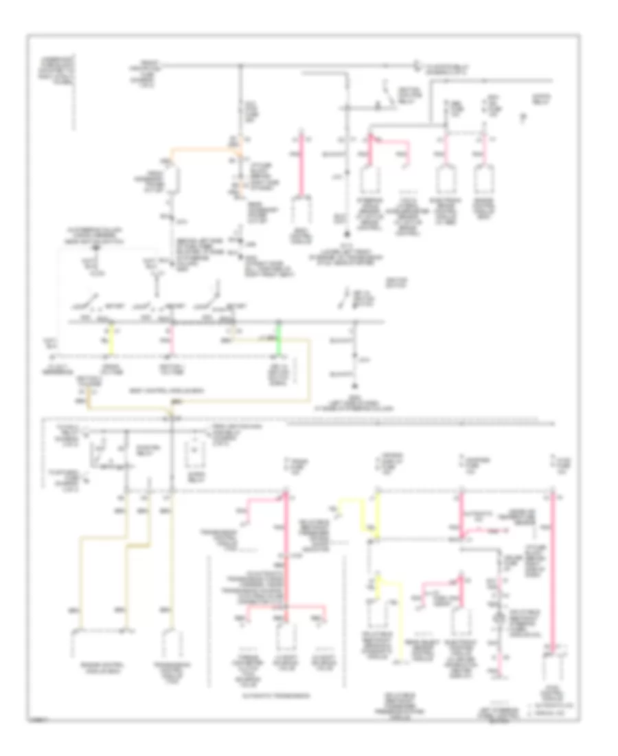 https://portal-diagnostov.com/license.html
Automotive Electricians Portal FZCO
Automotive Electricians Portal FZCO
https://portal-diagnostov.com/license.html
https://portal-diagnostov.com/license.html
Automotive Electricians Portal FZCO
Automotive Electricians Portal FZCOList of elements for 5.3L VIN C, Power Distribution Wiring Diagram (2 of 3) for Buick Allure Super 2008:
- (behind left side of dash knee bolster, at base of steering column) g200
- (in automatic transmission wiring harness, inside transmission housing, 19 cm from inline connector x113) j115
- (in steering column wiring harness, near ignition switch) j200
- 1-2 shift solenoid valve
- 12 volt reference
- 2-3 shift solenoid valve
- A x1
- A x2
- A10
- A2 x1
- Abs fuse 10a
- Acc
- Air bag/ display fuse 10a
- Automatic a/c
- Automatic transmission
- Aux pwr fuse 25a
- Body control module
- Body control module (bcm)
- C x2
- Compass fuse 10a
- Crank voltage
- Cruise fuse 2a
- D11
- E12
- Ecm ign fuse 10a
- Electronic brake control module (w/ abs)
- Electronic compass module (w/ driver information center display)
- Engine control module (ecm)
- From ignition main pcb relay (diagram 2 of 3)
- From wsw/rvc a fuse (diagram 1 of 3)
- Front accessory power outlet
- G113 (lower left front of engine, on transmission stud, near starter)
- G202 (left side of dash, at base of steering column)
- G302 (in right door sill, forward of right front seat)
- Hvac control module
- Hvac fuse 10a
- I/p fuse block (behind right side of dash)
- Ignition 1 voltage
- Ignition 3 voltage
- Ignition main pcb relay
- Ignition switch
- Inflatable restraint passenger air bag on/off indicator
- Inflatable restraint passenger presence system module
- Inflatable restraint sensing & diagnostic module
- Inflatable restraint steering wheel module coil
- Inside air temperature sensor
- J101
- J213
- J214
- J406
- Key in ignition switch
- Key in ignition switch signal
- Left steering wheel control switch
- Lock
- Manual a/c
- Nca
- Pnk
- Pwr/trn relay
- Rear accessory power outlet
- Rear object sensor control module
- Red
- Run
- Start
- Steering angle sensor (w/ active brake control)
- Strtr relay
- To etc/ecm fuse (diagram 3 of 3)
- To fan 2 relay (diagram 3 of 3)
- To strtr relay (diagram 2 of 3)
- Torque converter clutch (tcc) solenoid valve
- Trans fuse 10a
- Transmission control module (tcm)
- Underhood fuse block (mounted to right strut tower)
- W/ park assist
- X1 b
- X1 c2
- X100
- X2 b9
- X4 h1
- Yaw & lateral accelerometer sensor (w/ active brake control)
5.3L VIN C, Power Distribution Wiring Diagram (3 of 3) for Buick Allure Super 2008
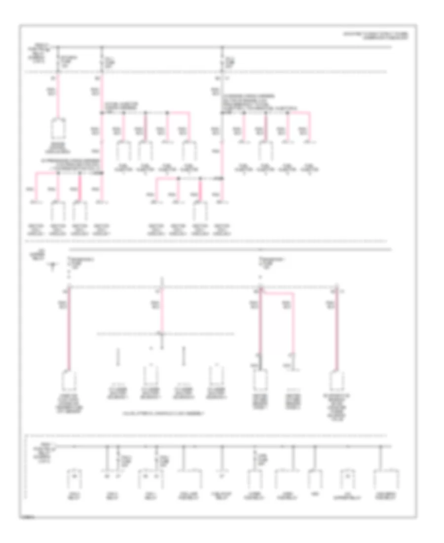 https://portal-diagnostov.com/license.html
Automotive Electricians Portal FZCO
Automotive Electricians Portal FZCO
https://portal-diagnostov.com/license.html
https://portal-diagnostov.com/license.html
Automotive Electricians Portal FZCO
Automotive Electricians Portal FZCOList of elements for 5.3L VIN C, Power Distribution Wiring Diagram (3 of 3) for Buick Allure Super 2008:
- (in engine wiring harness, on top of engine, 8 cm from breakout to fuel injector 3, towards fuel injector 5) j109
- (in fuel injector wiring harness) j108
- (in pre-engine wiring harness 5 cm from ignition coil 1 towards ignition coil 3) j106
- (mounted to right strut tower) underhood fuse block
- A/c cmprsr relay
- Cylinder shutoff solenoid 1
- Cylinder shutoff solenoid 4
- Cylinder shutoff solenoid 6
- Cylinder shutoff solenoid 7
- Emissions 1 fuse 15a
- Emissions 2 fuse 15a
- Engine control module (ecm)
- Etc/ecm fuse 15a
- Evaporative emission (evap) canister purge solenoid valve
- Fan 1 fuse 30a
- Fan 1 relay
- Fan 2 relay
- Fan 3 fuse 30a
- Fan 3 relay
- Fog lamp pcb relay
- From pwr/trn b relay (diagram 2 of 3)
- From pwr/trn d relay (diagram 2 of 3)
- Fuel injector
- Fuel/pump relay
- Hdm
- Heated oxygen sensor (ho2s) 1
- Heated oxygen sensor (ho2s) 2
- High beam pcb relay
- Horn pcb relay
- Ignition coil/ module 1
- Ignition coil/ module 2
- Ignition coil/ module 3
- Ignition coil/ module 4
- Ignition coil/ module 5
- Ignition coil/ module 6
- Ignition coil/ module 7
- Ignition coil/ module 8
- Inj 1 fuse 20a
- Inj 2 fuse 20a
- J105
- Mass air flow (maf)/ intake air temperature (iat) sensor
- Nca
- Pnk
- Valve lifter oil manifold (vlom) assembly
- Wiper pcb relay
- Wpr fuse 25a
POWER DOOR LOCKS
Power Door Locks Wiring Diagram (1 of 2) for Buick Allure Super 2008
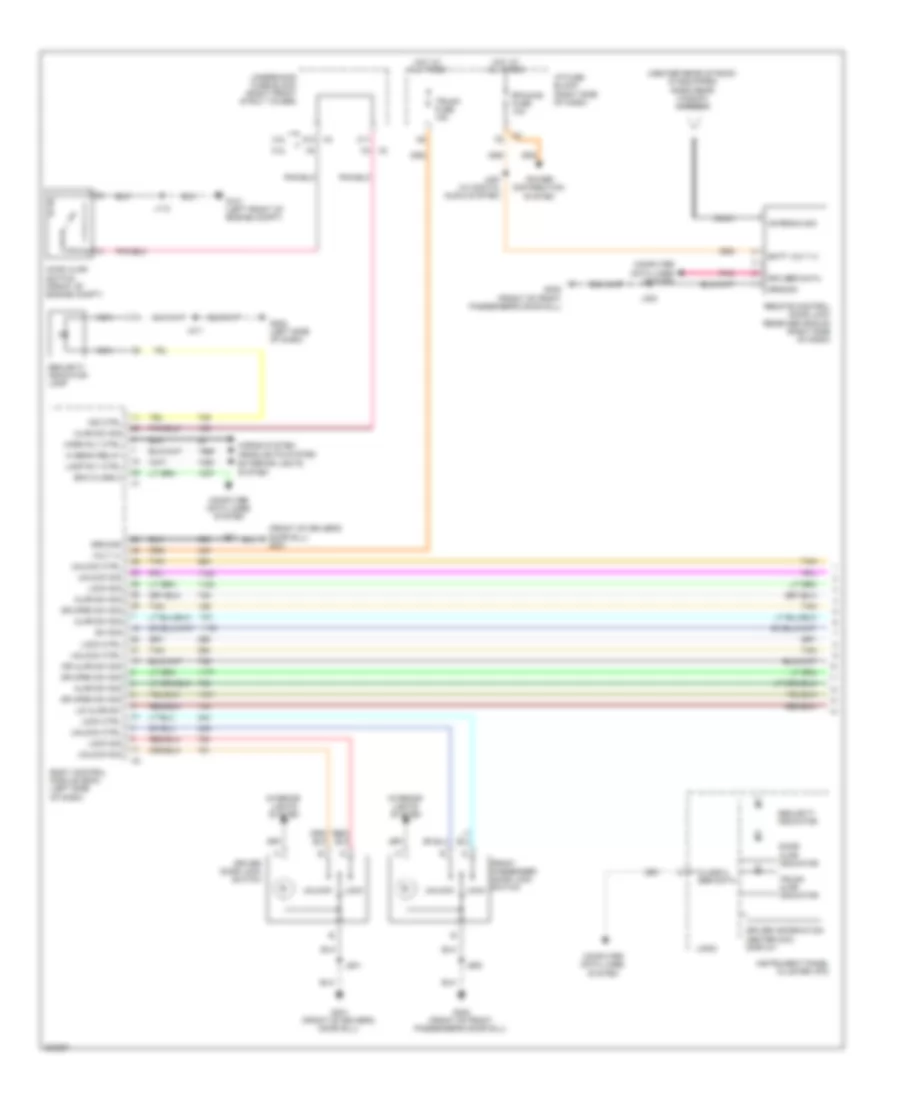 https://portal-diagnostov.com/license.html
Automotive Electricians Portal FZCO
Automotive Electricians Portal FZCO
https://portal-diagnostov.com/license.html
https://portal-diagnostov.com/license.html
Automotive Electricians Portal FZCO
Automotive Electricians Portal FZCOList of elements for Power Door Locks Wiring Diagram (1 of 2) for Buick Allure Super 2008:
- (center rear of roof) (if equipped) radio rear window antenna
- (front of driver's door sill) g301
- 3.8l
- 5.3l
- Ajar sw sig
- Antenna sig
- Batt volt (+)
- Bcm class 2
- Body control module (bcm) (left side of dash)
- C11
- C4 x2
- Class 2 ser data
- Coax
- Computer data lines system
- Door ajar indicator
- Dr ajar sw sig
- Dr open sw sig
- Driver door lock switch
- Driver information center (dic) display
- Front passenger door lock switch
- G101 (left front of engine compt)
- G202 (left side of dash)
- G301 (front of driver's door sill)
- G302 (front of front passenger's door sill)
- Ground
- Headlights system exterior lights system
- Hi beam relay
- Hood ajar switch (front of engine compt)
- Horn rly ctrl
- Horns system
- Hot at all times
- I/p fuse block (right side of dash)
- Ind ctrl
- Instrument panel cluster (ipc)
- Interior lights system
- J112
- J211
- J300
- J303
- J400 (w/ digital audio system)
- J501
- J605
- Lamp rly ctrl
- Lid ajar sw
- Lock
- Lock ctrl
- Lock sig
- Logic
- Nca
- Pnk
- Power distribution system
- Remote control door lock receiver (rcdlr) (right side of dash)
- Rfa ser data
- Rfa/mod fuse 10a
- Security indicator
- Security indicator lamp
- Sw sig
- Tan
- Trunk ajar indicator
- Trunk fuse 15a
- Underhood fuse block (right front strut tower)
- Unlock
- Unlock ctrl
- Unlock sig
- Volt (+)
- X3 c12
Power Door Locks Wiring Diagram (2 of 2) for Buick Allure Super 2008
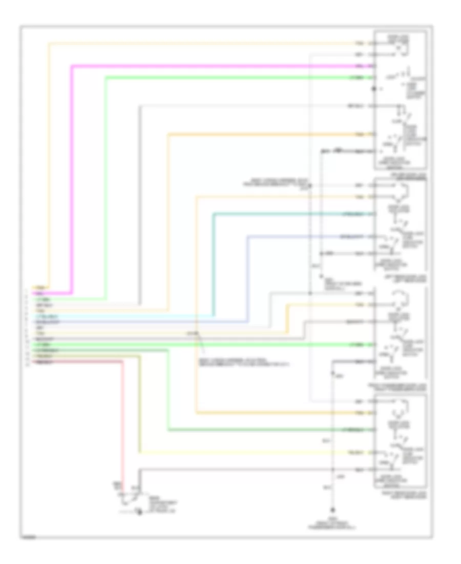 https://portal-diagnostov.com/license.html
Automotive Electricians Portal FZCO
Automotive Electricians Portal FZCO
https://portal-diagnostov.com/license.html
https://portal-diagnostov.com/license.html
Automotive Electricians Portal FZCO
Automotive Electricians Portal FZCOList of elements for Power Door Locks Wiring Diagram (2 of 2) for Buick Allure Super 2008:
- (body wiring harness, 26 cm from second breakout to g301) j315
- (body wiring harness, 29 cm from second breakout to inline connector x311)
- Ajar
- Door lock actuator
- Door lock ajar indicator switch
- Door lock cylinder switch
- Door lock open indicator switch
- Driver door lock (driver's door)
- Front passenger door lock (front passenger's door)
- G301 (front of driver's door sill)
- G302 (front of front passenger's door sill)
- J303
- J314
- J406
- J500
- J604
- Left rear door lock (left rear door)
- Lock
- Open
- Rear compartment lid latch (in trunk lid)
- Right rear door lock (right rear door)
- Tan
- Unlock
POWER MIRRORS
Electrochromic Mirror Wiring Diagram for Buick Allure Super 2008
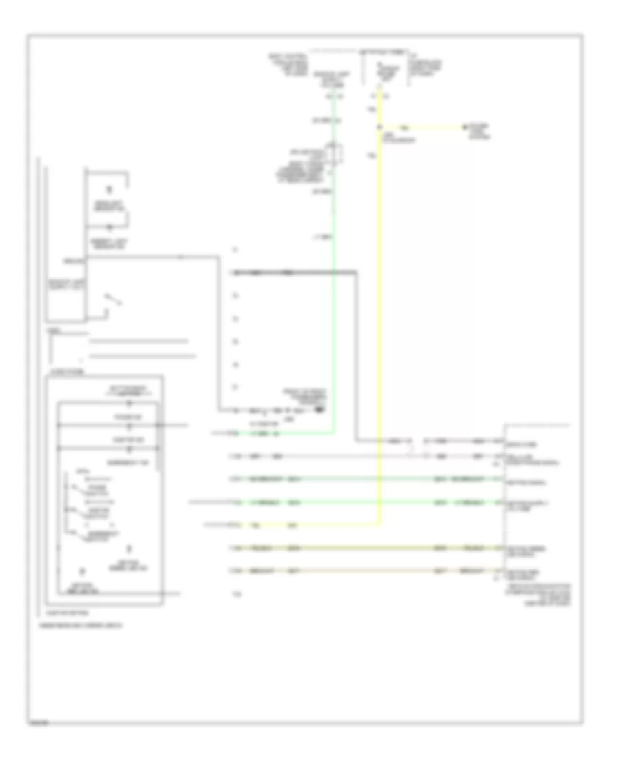 https://portal-diagnostov.com/license.html
Automotive Electricians Portal FZCO
Automotive Electricians Portal FZCO
https://portal-diagnostov.com/license.html
https://portal-diagnostov.com/license.html
Automotive Electricians Portal FZCO
Automotive Electricians Portal FZCOList of elements for Electrochromic Mirror Wiring Diagram for Buick Allure Super 2008:
- (front of front passenger's door sill) g302
- Ambient light sensor ind
- Body control module (bcm) (left side of dash)
- Button back lighting
- Cellular micro phone signal
- Drain wire
- Emergency ind
- Emergency switch
- F1 x2
- Ground
- Headlight sensor ind
- Hot at all times
- I/p fuse block (right side of dash)
- Inside rearview mirror (isrvm)
- J390
- J394 (w/ sunroof)
- Keypad green led ind
- Keypad green led signal
- Keypad red led ind
- Keypad red led signal
- Keypad signal
- Logic
- Micro phone
- Nca
- Onstar ind
- Onstar keypad
- Onstar switch
- Phone ind
- Phone switch
- Power tops system
- S/roof fuse 20a
- Splice pack jx307 (body wiring harness, under passenger seat, at rear carpet)
- Vehicle communication interface module (vcim) (w/ onstar) (center of dash)
- W/ onstar
Power Mirrors Wiring Diagram for Buick Allure Super 2008
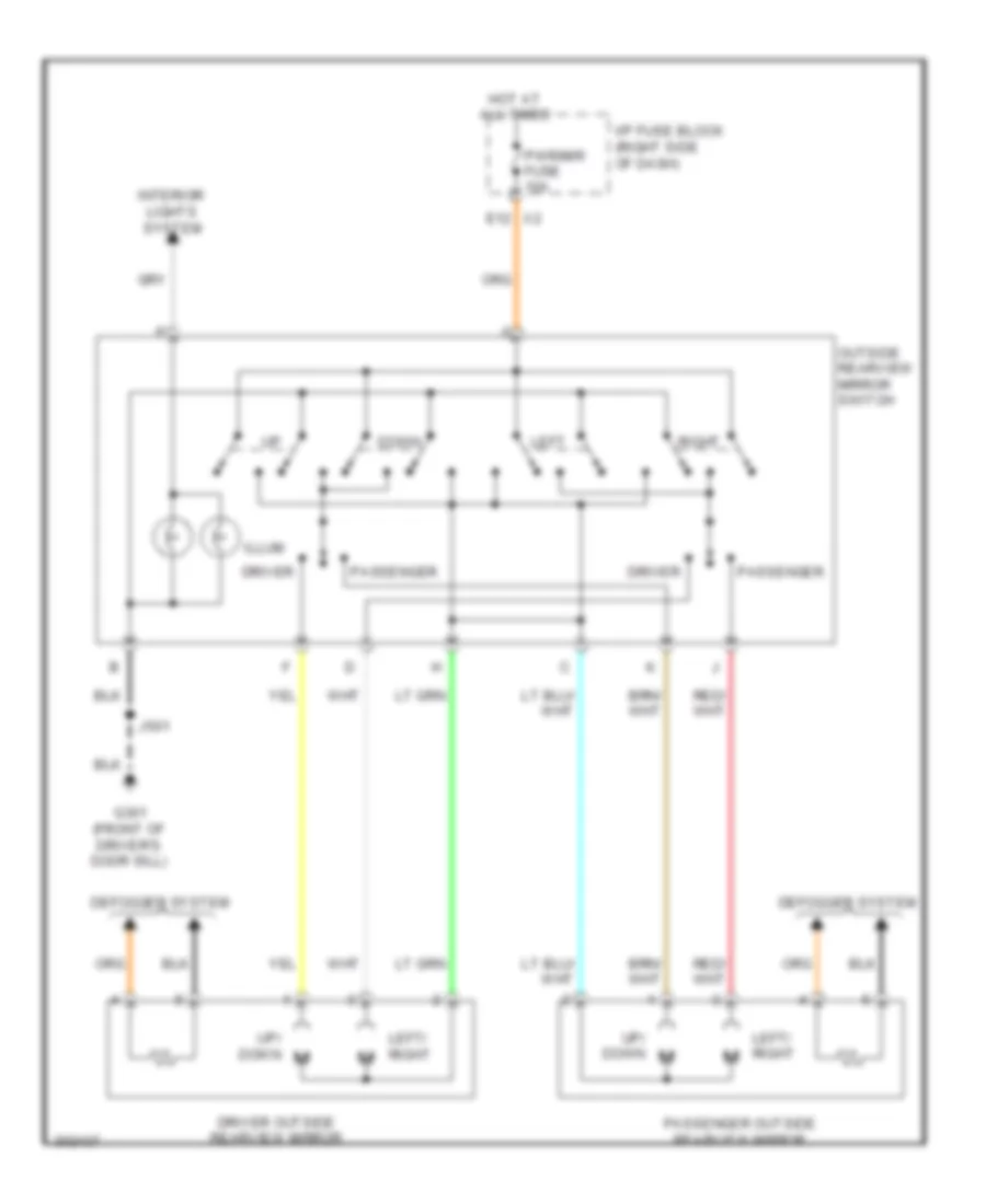 https://portal-diagnostov.com/license.html
Automotive Electricians Portal FZCO
Automotive Electricians Portal FZCO
https://portal-diagnostov.com/license.html
https://portal-diagnostov.com/license.html
Automotive Electricians Portal FZCO
Automotive Electricians Portal FZCOList of elements for Power Mirrors Wiring Diagram for Buick Allure Super 2008:
- Defogger system
- Down
- Driver
- Driver outside rearview mirror
- E12 x2
- G301 (front of driver's door sill)
- Hot at all times
- I/p fuse block (right side of dash)
- Illum
- Interior lights system
- J501
- Left
- Left/ right
- Outside rearview mirror switch
- Passenger
- Passenger outside rearview mirror
- Pwr/mir fuse 10a
- Right
- Up/ down
POWER SEATS
Driver Power Seat Wiring Diagram for Buick Allure Super 2008
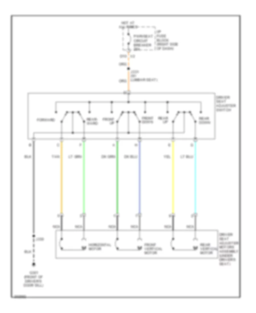 https://portal-diagnostov.com/license.html
Automotive Electricians Portal FZCO
Automotive Electricians Portal FZCO
https://portal-diagnostov.com/license.html
https://portal-diagnostov.com/license.html
Automotive Electricians Portal FZCO
Automotive Electricians Portal FZCOList of elements for Driver Power Seat Wiring Diagram for Buick Allure Super 2008:
- D10 x2
- Driver seat adjuster motors assembly (under driver's seat)
- Driver seat adjuster switch
- Forward
- Front down
- Front up
- Front vertical motor
- G301 (front of driver's door sill)
- Horizontal motor
- Hot at all times
- I/p fuse block (right side of dash)
- J330
- Nca
- Pwr/seat circuit breaker 25a
- Rear down
- Rear up
- Rear vertical motor
- Rear- ward
- Tan
Driver"s Lumbar Wiring Diagram for Buick Allure Super 2008
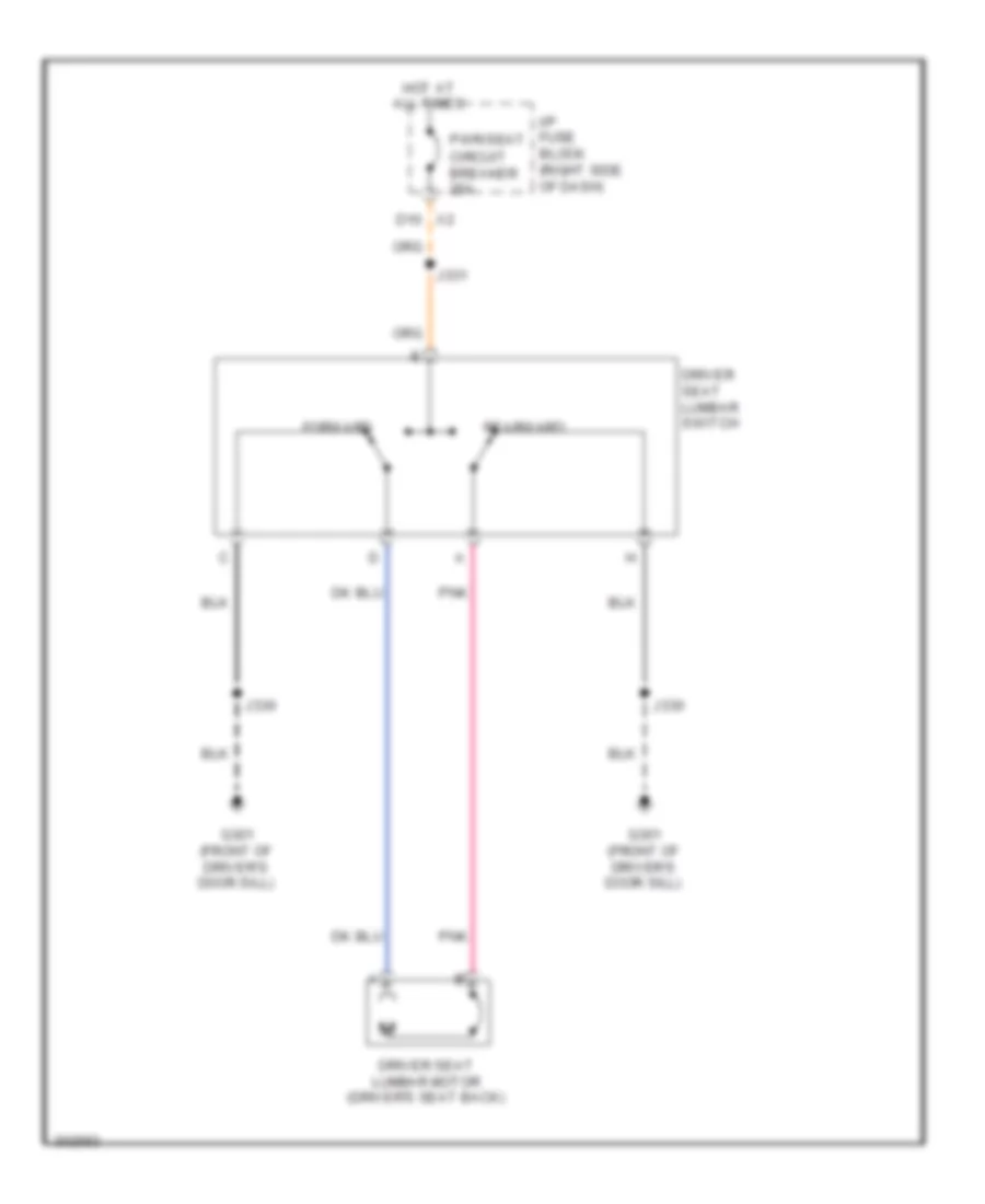 https://portal-diagnostov.com/license.html
Automotive Electricians Portal FZCO
Automotive Electricians Portal FZCO
https://portal-diagnostov.com/license.html
https://portal-diagnostov.com/license.html
Automotive Electricians Portal FZCO
Automotive Electricians Portal FZCOList of elements for Driver"s Lumbar Wiring Diagram for Buick Allure Super 2008:
- D10 x2
- Driver seat lumbar motor (driver's seat back)
- Driver seat lumbar switch
- Forward
- G301 (front of driver's door sill)
- Hot at all times
- I/p fuse block (right side of dash)
- J330
- J331
- Pnk
- Pwr/seat circuit breaker 25a
- Rearward
Heated Seats Wiring Diagram for Buick Allure Super 2008
 https://portal-diagnostov.com/license.html
Automotive Electricians Portal FZCO
Automotive Electricians Portal FZCO
https://portal-diagnostov.com/license.html
https://portal-diagnostov.com/license.html
Automotive Electricians Portal FZCO
Automotive Electricians Portal FZCOList of elements for Heated Seats Wiring Diagram for Buick Allure Super 2008:
- Automatic a/c
- Body control module (bcm) (left side of dash)
- Class 2 serial data
- Data link connector (dlc) (left side of dash)
- Driver back heated seat element (driver's seat back)
- Driver cushion heated seat element (driver's seat cushion)
- Driver heated seat high indicator
- Driver heated seat low indicator
- Driver heated seat switch
- Driver's heated seat relay (under driver's seat)
- Element
- Front passenger heated seat switch
- G301 (front of driver's door sill)
- Heated
- Heated seat element
- Heated seat thermistor
- Hot at all times
- Htd/seat fuse 20a
- Hvac control module (center of dash)
- I/p fuse block (right side of dash)
- Inflatable restraint front passenger presence system (pps) module (under front passenger's seat)
- J330
- J333
- J379
- Jx205 (clipped to knee bolster panel, right of data link connector)
- Logic
- Low reference
- Manual a/c
- Nca
- Passenger back heated seat element (front passenger's seat back)
- Passenger cushion heated seat element (front passenger's seat cushion)
- Passenger heated seat high indicator
- Passenger heated seat low indicator
- Passenger's heated seat relay (under front passenger's seat)
- Pnk
- Rly ctrl
- Seat
- Sensor sig
- Tan
- Thermistor
- X2 f9
Passenger"s Power Seat Wiring Diagram for Buick Allure Super 2008
 https://portal-diagnostov.com/license.html
Automotive Electricians Portal FZCO
Automotive Electricians Portal FZCO
https://portal-diagnostov.com/license.html
https://portal-diagnostov.com/license.html
Automotive Electricians Portal FZCO
Automotive Electricians Portal FZCOList of elements for Passenger"s Power Seat Wiring Diagram for Buick Allure Super 2008:
- C10 x2
- Forward
- Front down
- Front up
- Front vertical motor
- G301 (front of driver's door sill)
- Horizontal motor
- Hot at all times
- I/p fuse block (right side of dash)
- J333
- Nca
- Passenger seat adjuster motor assembly (under front passenger's seat)
- Passenger seat adjuster switch
- Pwr/seat circuit breaker 25a
- Rear down
- Rear up
- Rear vertical motor
- Rear- ward
- Tan
POWER TOP/SUNROOF
Power Top/Sunroof Wiring Diagram for Buick Allure Super 2008
 https://portal-diagnostov.com/license.html
Automotive Electricians Portal FZCO
Automotive Electricians Portal FZCO
https://portal-diagnostov.com/license.html
https://portal-diagnostov.com/license.html
Automotive Electricians Portal FZCO
Automotive Electricians Portal FZCOList of elements for Power Top/Sunroof Wiring Diagram for Buick Allure Super 2008:
- Accessory voltage
- Close
- G302 (front of front passenger's door sill)
- Ground
- Hot w/ rap relay energized
- I/p fuse block (right side of dash)
- J390
- J395
- Open signal
- Open/vent
- Red
- S/roof fuse 20a
- Sunroof control module
- Sunroof motor/ actuator (front of sunroof module)
- Sunroof switch
- Sunroof switch close signal
- Sunroof switch low reference
POWER WINDOWS
Power Windows Wiring Diagram for Buick Allure Super 2008
 https://portal-diagnostov.com/license.html
Automotive Electricians Portal FZCO
Automotive Electricians Portal FZCO
https://portal-diagnostov.com/license.html
https://portal-diagnostov.com/license.html
Automotive Electricians Portal FZCO
Automotive Electricians Portal FZCOList of elements for Power Windows Wiring Diagram for Buick Allure Super 2008:
- (body wiring harness, 26 cm from breakout to g301) j350
- Down
- Driver window motor (driver's door)
- Driver window switch
- Express down
- Front passenger window motor (front passenger's door)
- Front passenger window switch
- G301 (front of driver's door sill)
- G302 (front of front passenger's door sill)
- Hot w/ rap relay energized
- I/p fuse block (right side of dash)
- Illum
- Illumination
- Interior lights system
- J501
- J605
- Left rear window motor (left rear door)
- Left rear window switch
- Lock out switch
- Logic
- Pwr/wndw circuit breaker 25a
- Right rear window motor (right rear door)
- Right rear window switch
- Tan
- X1 f
- X2 e
RADIO
Radio Wiring Diagram, with Amplifier for Buick Allure Super 2008
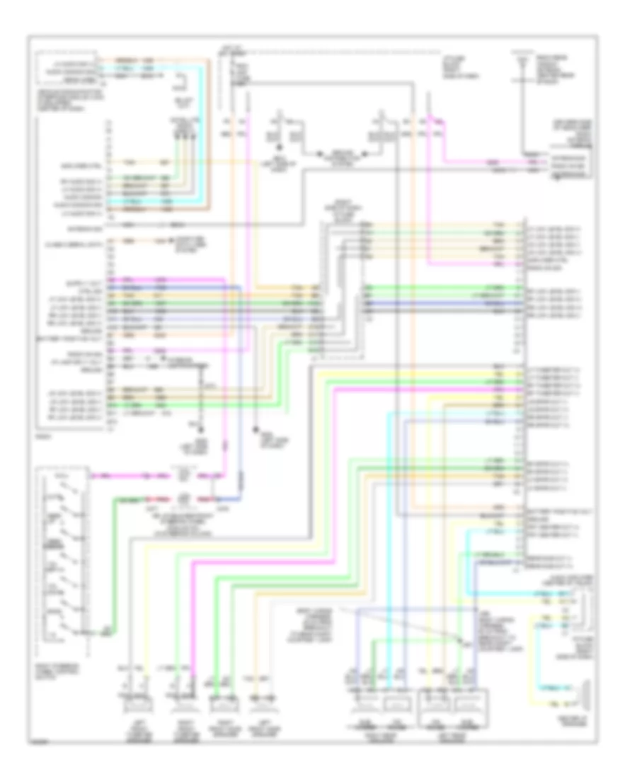 https://portal-diagnostov.com/license.html
Automotive Electricians Portal FZCO
Automotive Electricians Portal FZCO
https://portal-diagnostov.com/license.html
https://portal-diagnostov.com/license.html
Automotive Electricians Portal FZCO
Automotive Electricians Portal FZCOList of elements for Radio Wiring Diagram, with Amplifier for Buick Allure Super 2008:
- (body wiring harness, 45 cm from breakout to rear compt courtesy lamp)
- (driver's side of headliner) radio antenna module
- (right side of dash) i/p fuse block
- 1-6
- A10
- A11
- A12
- Amplifier ctrl
- Antenna sig
- Audio amplifier (center of trunk)
- Audio common
- Audio common sig
- B10
- B11
- B12
- Band
- Battery positive volt
- C10
- C11
- C12
- Center i/p speaker
- Class 2 serial data
- Coax
- Computer data lines system
- Ctrl sig
- Drain wire
- Frt center out (+)
- Frt center out (-)
- G200 (left side of dash)
- G202 (left side of dash)
- Ground
- Ground distribution system
- Hot at all times
- I/p fuse block (right side of dash)
- I/p lamp sply volt
- Inflatable restraint steering wheel module coil (in steering column)
- Interior lights system
- J213
- J360 (body wiring harness, 90 cm from breakout to rear compt courtesy lamp)
- J361
- Left front door speaker
- Left front tweeter speaker
- Left rear speaker
- Lf low level sig (+)
- Lf low level sig (-)
- Lf spkr out (+)
- Lf spkr out (-)
- Lf tweeter out (+)
- Lf tweeter out (-)
- Lh audio sig (+)
- Lr low level sig (+)
- Lr low level sig (-)
- Lr spkr out (+)
- Lr spkr out (-)
- Mid range
- Mute
- Nca
- Pnk
- Radio
- Radio on sig
- Radio rear window antenna (center rear of roof)
- Rdo/ amp fuse 25a
- Rear sub out (+)
- Rear sub out (-)
- Rf low level sig (+)
- Rf low level sig (-)
- Rf spkr out (+)
- Rf spkr out (-)
- Rf tweeter out (+)
- Rf tweeter out (-)
- Rh audio sig (+)
- Right front door speaker
- Right front tweeter speaker
- Right rear speaker
- Right steering wheel control switch
- Rr low level sig (+)
- Rr low level sig (-)
- Rr spkr out (+)
- Rr spkr out (-)
- Satellite radio circuit
- Seek down
- Seek up
- Sub- woofer
- Tan
- Vehicle communication interface module (vcim) (if equipped) (center of dash)
- Vol down
- Vol up
- X275
- X277
Radio Wiring Diagram, without Amplifier for Buick Allure Super 2008
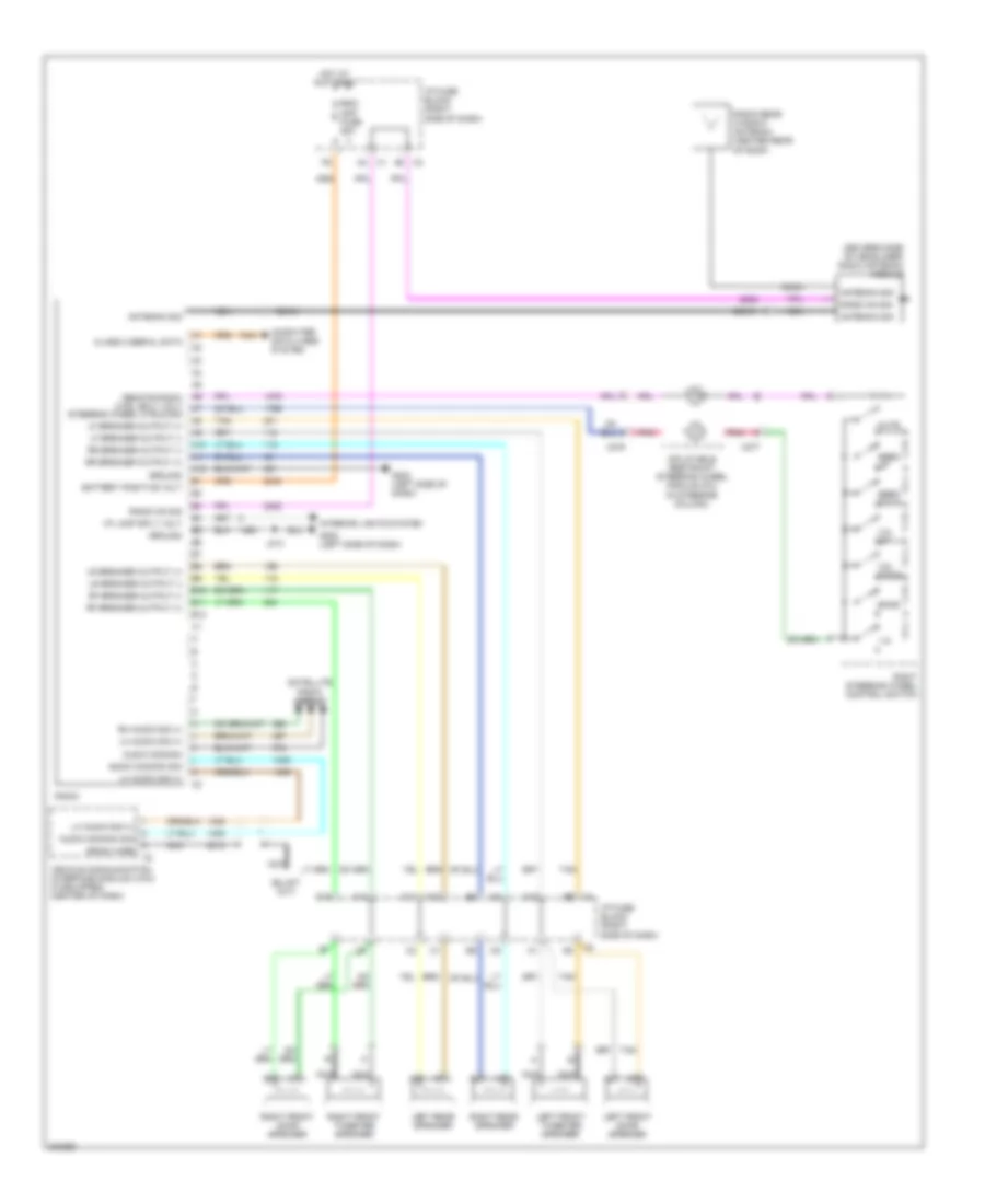 https://portal-diagnostov.com/license.html
Automotive Electricians Portal FZCO
Automotive Electricians Portal FZCO
https://portal-diagnostov.com/license.html
https://portal-diagnostov.com/license.html
Automotive Electricians Portal FZCO
Automotive Electricians Portal FZCOList of elements for Radio Wiring Diagram, without Amplifier for Buick Allure Super 2008:
- (driver's side of headliner) radio antenna module
- 1-6
- A10
- A11
- A12
- A4 x1
- A6 remote radio ctrl sply volt a7
- A9 x2
- Antenna sig
- Audio common
- Audio common sig
- B10
- B11
- B12
- Band
- Battery positive volt
- C10
- C11
- C12
- Class 2 serial data
- Coax
- Computer data lines system
- Drain wire
- G200 (left side of dash)
- G202 (left side of dash)
- Ground
- Hot at all times
- I/p fuse block (right side of dash)
- I/p lamp sply volt
- Inflatable restraint steering wheel module coil (in steering column)
- Interior lights system
- J213
- Left front door speaker
- Left front tweeter speaker
- Left rear speaker
- Lf speaker output (+)
- Lf speaker output (-)
- Lh audio sig (+)
- Lr speaker output (+)
- Lr speaker output (-)
- Mute
- Nca
- Pnk
- Radio
- Radio on sig
- Radio rear window antenna (center rear of roof)
- Rdo/ amp fuse 25a
- Rf speaker output (+)
- Rf speaker output (-)
- Rh audio sig (+)
- Right front door speaker
- Right front tweeter speaker
- Right rear speaker
- Right steering wheel control switch
- Rr speaker output (+)
- Rr speaker output (-)
- Satellite radio circuit
- Seek down
- Seek up
- Steering wheel ctrls sig
- Tan
- Vehicle communication interface module (vcim) (if equipped) (center of dash)
- Vol down
- Vol up
- X275
- X277
Satellite Radio Wiring Diagram for Buick Allure Super 2008
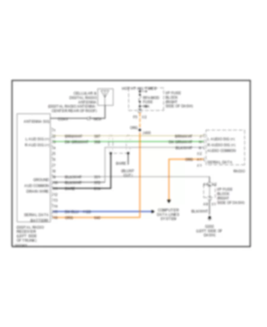 https://portal-diagnostov.com/license.html
Automotive Electricians Portal FZCO
Automotive Electricians Portal FZCO
https://portal-diagnostov.com/license.html
https://portal-diagnostov.com/license.html
Automotive Electricians Portal FZCO
Automotive Electricians Portal FZCOList of elements for Satellite Radio Wiring Diagram for Buick Allure Super 2008:
- Antenna sig
- Aud common
- Audio common
- Bare
- Battery
- Cellular & digital radio antenna (digital radio antenna: center rear of roof)
- Coax
- Computer data lines system
- Digital radio receiver (left side of trunk)
- Drain wire
- F5 x2
- G202 (left side of dash)
- Ground
- Hot at all times
- I/p fuse block (right side of dash)
- I/p fuse block (right side of dash) x1
- J400
- L aud sig (+)
- L audio sig (+)
- Nca
- R aud sig (+)
- R audio sig (+)
- Radio
- Rfa/mod fuse 10a
- Serial data
SHIFT INTERLOCK
Ignition Lock Solenoid Wiring Diagram, with Console Shift for Buick Allure Super 2008
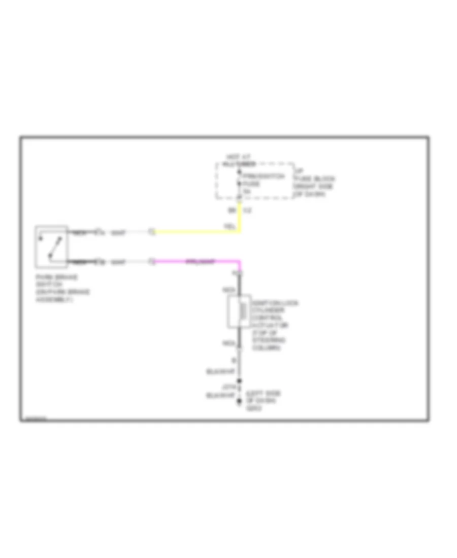 https://portal-diagnostov.com/license.html
Automotive Electricians Portal FZCO
Automotive Electricians Portal FZCO
https://portal-diagnostov.com/license.html
https://portal-diagnostov.com/license.html
Automotive Electricians Portal FZCO
Automotive Electricians Portal FZCOList of elements for Ignition Lock Solenoid Wiring Diagram, with Console Shift for Buick Allure Super 2008:
- (left side of dash) g202
- Hot at all times
- I/p fuse block (right side of dash)
- Ignition lock cylinder control actuator (top of steering column)
- J214
- Nca
- Park brake switch (on park brake assembly)
- Prk/switch fuse 5a
3.6L VIN 7
3.6L VIN 7, Shift Interlock Wiring Diagram for Buick Allure Super 2008
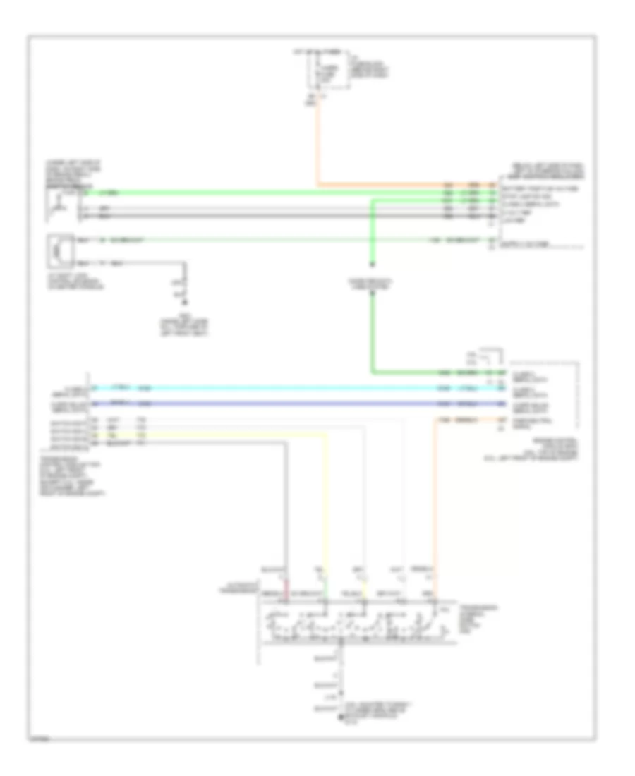 https://portal-diagnostov.com/license.html
Automotive Electricians Portal FZCO
Automotive Electricians Portal FZCO
https://portal-diagnostov.com/license.html
https://portal-diagnostov.com/license.html
Automotive Electricians Portal FZCO
Automotive Electricians Portal FZCOList of elements for 3.6L VIN 7, Shift Interlock Wiring Diagram for Buick Allure Super 2008:
- (3.6l: mounted to bank 1 cylinder head above exhaust manifold) g115
- (below left side of dash, left of steering column) body control module (bcm)
- (under left side of dash, on right side of brake pedal) brake pedal position sensor
- 3.6l
- 5 volt ref
- 5.3l
- A/t shift lock control solenoid (in center console)
- Automatic transmission
- Battery positive voltage
- Class 2 serial data
- Computer data lines system
- E5 x1
- Engine control module (ecm) (3.6l: top of engine) (5.3l: left front of engine compt)
- G301 (inside left door sill, forward of left front seat)
- Hazrd fuse 20a
- Hi-spd gmlan serial data
- Hot at all times
- I/p fuse block (behind right side of dash)
- J116
- J303
- Low ref
- P/n
- Park/neutral signal
- Stop lamp sw sig
- Switch sig a
- Switch sig b
- Switch sig c
- Switch sig p
- Transmission control module (tcm) (5.3l: left front of engine compt) (except 5.3l: inside air cleaner, left front of engine compt)
- Transmission internal mode switch (ims)
3.8L VIN 2
3.8L VIN 2, Shift Interlock Wiring Diagram for Buick Allure Super 2008
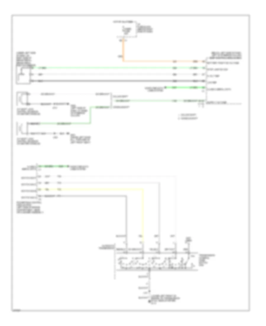 https://portal-diagnostov.com/license.html
Automotive Electricians Portal FZCO
Automotive Electricians Portal FZCO
https://portal-diagnostov.com/license.html
https://portal-diagnostov.com/license.html
Automotive Electricians Portal FZCO
Automotive Electricians Portal FZCOList of elements for 3.8L VIN 2, Shift Interlock Wiring Diagram for Buick Allure Super 2008:
- (below left side of dash, left of steering column) body control module (bcm)
- (lower left front of engine, on transmission stud, near starter) g113
- (not used) w
- (under left side of dash, on right side of brake pedal) brake pedal position sensor
- 5 volt ref
- A/t shift lock control solenoid (in center console)
- Automatic transmission
- Battery positive voltage
- Class 2 serial data
- Class 2 serial data x1
- Column shift
- Computer data lines system
- Console shift
- E5 x1
- G202 (left side of dash, at base of steering column)
- G301 (inside left door sill, forward of left front seat)
- Hazrd fuse 20a
- Hot at all times
- I/p fuse block (behind right side of dash)
- J101
- J214
- J303
- Low ref
- P/n
- Powertrain control module (pcm) (left side of engine compartment, near air cleaner assembly)
- Stop lamp sw sig
- Switch sig a
- Switch sig b
- Switch sig c
- Switch sig p
- Transmission internal mode switch (ims)
5.3L VIN C
5.3L VIN C, Shift Interlock Wiring Diagram for Buick Allure Super 2008
 https://portal-diagnostov.com/license.html
Automotive Electricians Portal FZCO
Automotive Electricians Portal FZCO
https://portal-diagnostov.com/license.html
https://portal-diagnostov.com/license.html
Automotive Electricians Portal FZCO
Automotive Electricians Portal FZCOList of elements for 5.3L VIN C, Shift Interlock Wiring Diagram for Buick Allure Super 2008:
- (3.6l: mounted to bank 1 cylinder head above exhaust manifold) g115
- (below left side of dash, left of steering column) body control module (bcm)
- (under left side of dash, on right side of brake pedal) brake pedal position sensor
- 3.6l
- 5 volt ref
- 5.3l
- A/t shift lock control solenoid (in center console)
- Automatic transmission
- Battery positive voltage
- Class 2 serial data
- Computer data lines system
- E5 x1
- Engine control module (ecm) (3.6l: top of engine) (5.3l: left front of engine compt)
- G301 (inside left door sill, forward of left front seat)
- Hazrd fuse 20a
- Hi-spd gmlan serial data
- Hot at all times
- I/p fuse block (behind right side of dash)
- J116
- J303
- Low ref
- P/n
- Park/neutral signal
- Stop lamp sw sig
- Switch sig a
- Switch sig b
- Switch sig c
- Switch sig p
- Transmission control module (tcm) (5.3l: left front of engine compt) (except 5.3l: inside air cleaner, left front of engine compt)
- Transmission internal mode switch (ims)
STARTING/CHARGING
Charging Wiring Diagram for Buick Allure Super 2008
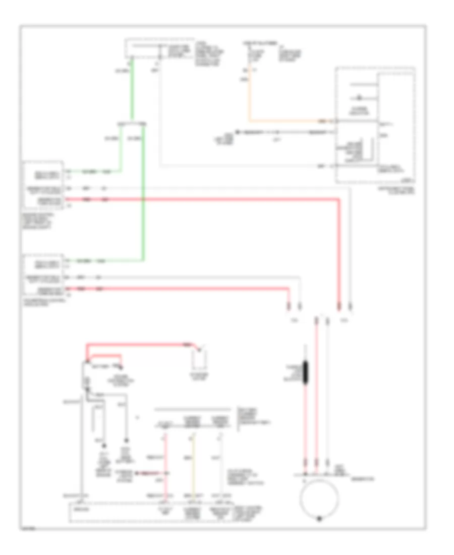 https://portal-diagnostov.com/license.html
Automotive Electricians Portal FZCO
Automotive Electricians Portal FZCO
https://portal-diagnostov.com/license.html
https://portal-diagnostov.com/license.html
Automotive Electricians Portal FZCO
Automotive Electricians Portal FZCOList of elements for Charging Wiring Diagram for Buick Allure Super 2008:
- (in i/p wiring harness, 21 cm from lamp assembly switch)
- (not used) a
- 10 volt ref
- 3.8l
- 5.3l
- Batt +
- Battery
- Battery current sensor (near battery)
- Body control module (bcm) (left side of dash)
- Charge indicator
- Clstr fuse 10a
- Computer data lines system
- Current sensor low ref
- Current sensor sig
- Driver information center (dic) display
- Ecm class 2 serial data
- Engine control module (ecm) (left front of engine compt)
- G102 (3.8l: near battery)
- G111 (3.8l: lower left rear of engine)
- G202 (left side of dash)
- Generator
- Generator field duty cycle sig
- Generator turn on sig
- Gnd
- Ground
- Hot at all times
- I/p class 2 serial data
- I/p fuse block (right side of dash)
- Instrument panel cluster (ipc)
- Interior lights system
- J204
- J211
- Jx205 (clipped to knee bolster panel, right of data link connector)
- Logic
- Pcm class 2 serial data
- Power distribution system
- Powertrain control module (pcm)
- Red
- Remote st sensor sig
- Starter motor
3.6L VIN 7
3.6L VIN 7, Starting Wiring Diagram for Buick Allure Super 2008
 https://portal-diagnostov.com/license.html
Automotive Electricians Portal FZCO
Automotive Electricians Portal FZCO
https://portal-diagnostov.com/license.html
https://portal-diagnostov.com/license.html
Automotive Electricians Portal FZCO
Automotive Electricians Portal FZCOList of elements for 3.6L VIN 7, Starting Wiring Diagram for Buick Allure Super 2008:
- (3.6l: top of engine) (3.8l: left side of engine compt, near air cleaner assembly) (3.8l) powertrain control module (pcm) (3.6l) engine control module (ecm)
- 12-volt ref
- 3.6l
- 3.8l
- Acc
- Battery
- Battery positive
- Body control module (bcm) (behind left side of dash, left of steering column)
- C11
- C12
- Charging circuit
- Class 2 serial data
- Clstr fuse 10a
- Crank relay
- Crank voltage
- Driver information center (dic) display
- G101 (left side of front end upper tie bar, in back of headlamp)
- G102 (3.6l: below right front strut tower) (3.8l: near battery)
- G111 (3.6l: lower left front of engine, on transmission stud, near starter) (3.8l: lower left side of engine)
- Ground distribution system
- Hold- in coil
- Hood ajar switch (w/ remote keyless entry) (front of engine compt)
- Hood ajar switch sig
- Hot at all times
- Hot w/ ign 1 relay energized
- I/p fuse block (behind right side of dash)
- Ignition 1 voltage
- Ignition switch
- Instrument panel cluster (ipc)
- J112
- J200
- Jx205 (clipped to knee bolster panel, right of data link connector)
- Lock
- Logic
- Pcm fuse 15 10a
- Pnk
- Power distribution system
- Pull- in coil
- Red
- Run
- Start
- Start enable rly ctrl
- Starter
- Starter fuse 33 40a
- Underhood fuse block (mounted to right strut tower)
3.8L VIN 2
3.8L VIN 2, Starting Wiring Diagram for Buick Allure Super 2008
 https://portal-diagnostov.com/license.html
Automotive Electricians Portal FZCO
Automotive Electricians Portal FZCO
https://portal-diagnostov.com/license.html
https://portal-diagnostov.com/license.html
Automotive Electricians Portal FZCO
Automotive Electricians Portal FZCOList of elements for 3.8L VIN 2, Starting Wiring Diagram for Buick Allure Super 2008:
- (3.6l: top of engine) (3.8l: left side of engine compt, near air cleaner assembly) (3.8l) powertrain control module (pcm) (3.6l) engine control module (ecm)
- 12-volt ref
- 3.6l
- 3.8l
- Acc
- Battery
- Battery positive
- Body control module (bcm) (behind left side of dash, left of steering column)
- C11
- C12
- Charging circuit
- Class 2 serial data
- Clstr fuse 10a
- Crank relay
- Crank voltage
- Driver information center (dic) display
- G101 (left side of front end upper tie bar, in back of headlamp)
- G102 (3.6l: below right front strut tower) (3.8l: near battery)
- G111 (3.6l: lower left front of engine, on transmission stud, near starter) (3.8l: lower left side of engine)
- Ground distribution system
- Hold- in coil
- Hood ajar switch (w/ remote keyless entry) (front of engine compt)
- Hood ajar switch sig
- Hot at all times
- Hot w/ ign 1 relay energized
- I/p fuse block (behind right side of dash)
- Ignition 1 voltage
- Ignition switch
- Instrument panel cluster (ipc)
- J112
- J200
- Jx205 (clipped to knee bolster panel, right of data link connector)
- Lock
- Logic
- Pcm fuse 15 10a
- Pnk
- Power distribution system
- Pull- in coil
- Red
- Run
- Start
- Start enable rly ctrl
- Starter
- Starter fuse 33 40a
- Underhood fuse block (mounted to right strut tower)
5.3L VIN C
5.3L VIN C, Starting Wiring Diagram for Buick Allure Super 2008
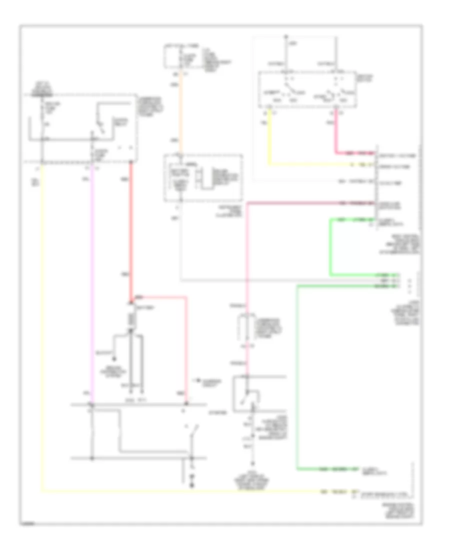 https://portal-diagnostov.com/license.html
Automotive Electricians Portal FZCO
Automotive Electricians Portal FZCO
https://portal-diagnostov.com/license.html
https://portal-diagnostov.com/license.html
Automotive Electricians Portal FZCO
Automotive Electricians Portal FZCOList of elements for 5.3L VIN C, Starting Wiring Diagram for Buick Allure Super 2008:
- 12-volt ref
- Acc
- Battery
- Battery positive
- Body control module (bcm) (behind left side of dash, left of steering column)
- Charging circuit
- Class 2 serial data
- Clstr fuse 10a
- Crank voltage
- Driver information center (dic) display
- Ecm ign fuse 10a
- Engine control module (ecm) (left front of engine compt)
- G101 (left side of front end upper tie bar, in back of headlamp)
- G102
- G111
- Ground distribution system
- Hood ajar switch (w/ remote keyless entry) (front of engine compt)
- Hood ajar switch sig
- Hot at all times
- Hot w/ ign main pcb relay energized
- I/p fuse block (behind right side of dash)
- Ignition 1 voltage
- Ignition switch
- Instrument panel cluster (ipc)
- J112
- J200
- Jx205 (clipped to knee bolster panel, right of data link connector)
- Lock
- Logic
- Pnk
- Red
- Run
- Start
- Start enable rly ctrl
- Starter
- Strtr fuse 40a
- Strtr relay
- Underhood fuse block (mounted to right strut tower)
SUPPLEMENTAL RESTRAINTS
Supplemental Restraints Wiring Diagram (1 of 2) for Buick Allure Super 2008
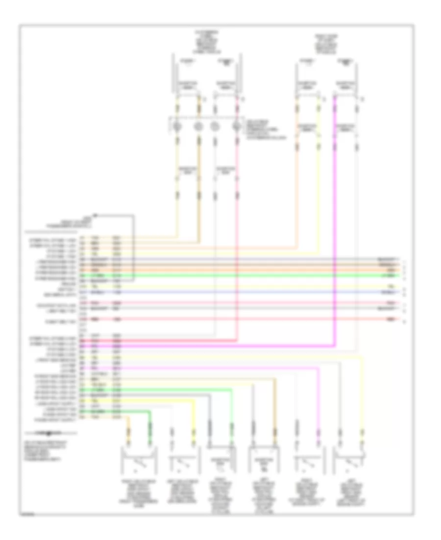 https://portal-diagnostov.com/license.html
Automotive Electricians Portal FZCO
Automotive Electricians Portal FZCO
https://portal-diagnostov.com/license.html
https://portal-diagnostov.com/license.html
Automotive Electricians Portal FZCO
Automotive Electricians Portal FZCOList of elements for Supplemental Restraints Wiring Diagram (1 of 2) for Buick Allure Super 2008:
- (in steering wheel) inflatable restraint steering wheel module
- (right siide of dash) inflatable restraint i/p module
- A10
- A11
- A12
- A13
- A14
- A15
- A16
- A17
- A18
- Case ground
- G302 (front of front passenger's door sill)
- Ground
- I/p stage 1 high
- I/p stage 1 low
- I/p stage 2 high
- I/p stage 2 low
- Ignition 1
- Inflatable restraint sensing & diagnostic module (sdm) (under front passenger's seat)
- Inflatable restraint steering wheel module coil (in steering column)
- L front end sens sig
- L pretensioner high
- L pretensioner low
- L seat belt sw
- L side impact sig
- Left inflatable restraint front end sensor (left front of engine compt)
- Left inflatable restraint roof rail module (if equipped) (mounted on left "c" pillar)
- Left inflatable restraint side impact (sis) sensor (if equipped) (driver's door)
- Lf roof rail mod high
- Lf roof rail mod low
- Low ref
- Occupant data link
- Pnk
- R front end sens sig
- R pretensioner high
- R pretensioner low
- R seat belt sw
- R side impact sig
- Red
- Rf roof rail mod high
- Rf roof rail mod low
- Right inflatable restraint front end sensor (at right front of engine compt)
- Right inflatable restraint roof rail module (if equipped) (mounted on right "c" pillar)
- Right inflatable restraint side impact (sis) sensor (if equipped) (front passenger's door)
- Sdm serial data
- Shorting bar
- Stage 1
- Stage 2
- Steer whl stage 1 high
- Steer whl stage 1 low
- Steer whl stage 2 high
- Steer whl stage 2 low
- Tan
Supplemental Restraints Wiring Diagram (2 of 2) for Buick Allure Super 2008
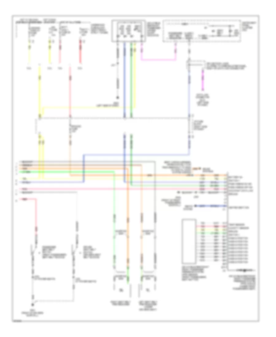 https://portal-diagnostov.com/license.html
Automotive Electricians Portal FZCO
Automotive Electricians Portal FZCO
https://portal-diagnostov.com/license.html
https://portal-diagnostov.com/license.html
Automotive Electricians Portal FZCO
Automotive Electricians Portal FZCOList of elements for Supplemental Restraints Wiring Diagram (2 of 2) for Buick Allure Super 2008:
- (body wiring harness, approximately 5 cm from breakout to g302) (w/ digital audio system s-band) j400
- 3.8l
- 5.3l
- A11
- Air bag ind
- Air bag off ind
- Air bag on ind
- Air bag/ display fuse 10a
- B10
- B11
- Batt 1 fuse 50a
- Batt main 1 fuse 26 40a
- Battery b+
- Case ground
- Class 2 (sdm)
- Class 2 serial data
- Data link connector (dlc) (left side of dash)
- Driver seat belt switch (driver's seat belt buckle)
- G202 (left side of dash)
- G301 (front of driver's door sill)
- G302 (front of front passenger's door sill)
- Ground
- Heated seat sig
- Hot at all times
- Hot in run or start
- Hot w/ ign main pcb relay energized
- Humidity sensor
- I/p fuse block (right side of dash)
- Ignition 1
- Inflatable restraint front passenger presence system (pps) module (under front passenger's seat)
- Inflatable restraint front passenger presence system (pps) sensor (front passenger's seat bottom)
- Inflatable restraint passenger air bag on/off indicator
- Instrument panel cluster (ipc)
- J211
- J300
- J330 (w/ power seats)
- J333 (w/ power seats)
- Left seat belt pretensioner (under driver's seat)
- Logic
- Mass & position
- Nca
- Occupant data link
- Pass airbag off ind
- Pass airbag on ind
- Passenger seat belt indicator
- Passenger seat belt switch (front passenger's seat belt buckle)
- Pnk
- Red
- Rfa/mod fuse 10a
- Right seat belt pretensioner
- Seat belt ind
- Seats system
- Shorting bar
- Sir fuse 10a
- Sound systems
- Splice pack jx205 (clipped to knee bolster panel, right of data link connector)
- Temp sensor
- Underhood fuse block (right front strut tower)
TRANSMISSION
3.6L VIN 7
3.6L VIN 7, Transmission Wiring Diagram for Buick Allure Super 2008
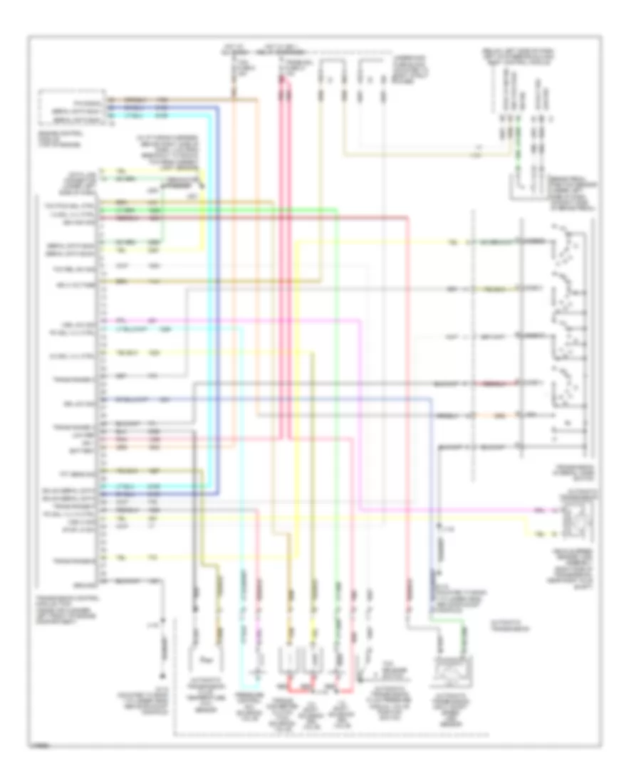 https://portal-diagnostov.com/license.html
Automotive Electricians Portal FZCO
Automotive Electricians Portal FZCO
https://portal-diagnostov.com/license.html
https://portal-diagnostov.com/license.html
Automotive Electricians Portal FZCO
Automotive Electricians Portal FZCOList of elements for 3.6L VIN 7, Transmission Wiring Diagram for Buick Allure Super 2008:
- (below left side of dash, left of steering column) body control module
- (in i/p wiring harness, behind right side of dash, 4 cm from breakout to rcdlr, towards ambient light sensor)
- 1-2 shift solenoid (ss) valve
- 1-2 sol vlv ctrl
- 10 volt ref
- 2-3 shift solenoid (ss) valve
- 2-3 sol vlv ctrl
- A red
- Automatic transmission
- Automatic transmission fluid pressure manual valve position switch
- Automatic transmission fluid temperature (tft) sensor
- Automatic transmission input shaft speed (iss) sensor
- Battery
- Brake pedal position sensor (under left side of dash, on right side of brake pedal)
- Code a
- Code b
- Code c
- Data link connector (under left side of dash)
- Engine control module (top of engine)
- G115 (mounted to bank 1 cylinder head above exhaust manifold)
- Gmlan serial data
- Ground
- Hot at all times
- Hot w/ ign 1 relay energized
- Ign 1
- Ign 3 voltage
- Iss high sig
- Iss low sig
- J115
- J116
- J201
- J202
- Low ref
- P/n
- P/n signal
- Parity
- Pc sol vlv ctrl
- Pc sol vlv hi ctrl
- Pnk
- Pressure control (pc) solenoid valve
- Red
- Serial data bus +
- Serial data bus -
- Serial data bus+
- Serial data bus-
- Stop lp sw
- Stop lp sw sig
- Sw sig
- Tan b
- Tcc pwm sol ctrl
- Tcc rel sw sig
- Tcc release switch
- Tcm fuse 8 15a
- Terminator resistor
- Tft sens sig
- Torque converter clutch (tcc) solenoid valve
- Trans range a
- Trans range b
- Trans range c
- Trans range p
- Trans sol fuse 21 10a
- Transmission control module (tcm) (inside air cleaner, left front of engine compartment)
- Transmission internal mode switch
- Underhood fuse block (mounted to right strut x1 tower)
- Vehicle speed sensor (vss) assembly (right side of transmission, near right axle shaft)
- Vss hi sig
- Vss low sig
3.8L VIN 2
3.8L VIN 2, Transmission Wiring Diagram for Buick Allure Super 2008
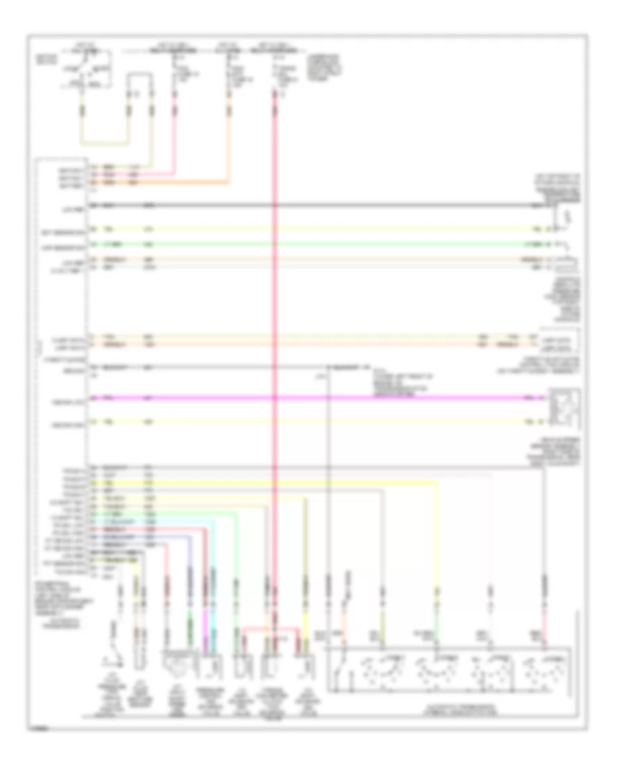 https://portal-diagnostov.com/license.html
Automotive Electricians Portal FZCO
Automotive Electricians Portal FZCO
https://portal-diagnostov.com/license.html
https://portal-diagnostov.com/license.html
Automotive Electricians Portal FZCO
Automotive Electricians Portal FZCOList of elements for 3.8L VIN 2, Transmission Wiring Diagram for Buick Allure Super 2008:
- (not used)
- (on top right of intake manifold)
- (throttle pos)
- 1-2 shift sol
- 1-2 shift solenoid (ss) valve
- 2-3 shift sol
- 2-3 shift solenoid (ss) valve
- 5 volt ref 1
- A/t fluid pressure (tfp) manual valve position
- A/t fluid temp- erature sensor
- A/t input shaft speed (iss) speed
- Acc
- At iss sig high
- At iss sig low
- Automatic transmission
- Automatic transmission internal mode switch (ims)
- Battery
- Code a
- Code b
- Code c
- Ect sensor sig
- Engine coolant temperature (ect) sensor
- G113 (lower left front of engine, on transmission stud, near starter)
- Ground
- Hot at all times
- Hot w/ ign 1 relay energized
- Ignition 1
- Ignition 3
- Ignition switch
- J101
- J115
- Lock
- Low ref
- Manifold absolute pressure (map) sensor (top right side of intake manifold)
- Map sensor sig
- Parity
- Pc sol high
- Pc sol low
- Pcm fuse 15 10a
- Pcm/ etc fuse 16 15a
- Pnk
- Powertrain control module (left side of engine compartment, near air cleaner assembly)
- Pressure control (ps) solenoid valve
- Red
- Red a
- Run
- Start
- Switch
- Tan
- Tan b
- Tcc sol
- Tcc sw sig
- Tft sensor sig
- Throttle actuator control (tac) module (on throttle body assembly)
- Torque converter clutch (tcc) solenoid valve
- Tr sig a
- Tr sig b
- Tr sig c
- Tr sig p
- Trans sol fuse 21 10a
- Uart data
- Underhood fuse block (mounted to right strut tower)
- Vehicle speed sensor assembly (right side of transmission, near right axle shaft)
- Vss sig high
- Vss sig low
5.3L VIN C
5.3L VIN C, Transmission Wiring Diagram for Buick Allure Super 2008
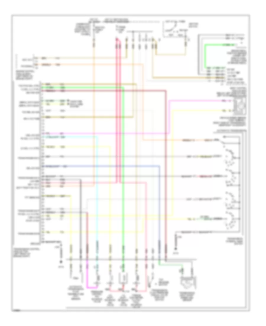 https://portal-diagnostov.com/license.html
Automotive Electricians Portal FZCO
Automotive Electricians Portal FZCO
https://portal-diagnostov.com/license.html
https://portal-diagnostov.com/license.html
Automotive Electricians Portal FZCO
Automotive Electricians Portal FZCOList of elements for 5.3L VIN C, Transmission Wiring Diagram for Buick Allure Super 2008:
- 1-2 shift solenoid (ss) valve
- 1-2 sol vlv ctrl
- 10 volt ref
- 2-3 shift solenoid (ss) valve
- 2-3 sol vlv ctrl
- Acc
- Acc volt
- Automatic transmission
- Automatic transmission fluid temperature (tft) sensor
- Batt positive volt
- Body control module (bcm) (below left side of dash, left of steering column)
- Brake pedal position sensor (under left side of dash, on right side of brake pedal)
- Code a
- Code b
- Code c
- Computer data lines system
- Emc/tcm fuse 8 15a
- Engine control module (ecm) (left front of engine compt)
- G115
- Ground
- Hot at all times
- Hot w/ ignition main pcb relay energized
- Ign 1 volt
- Ign 3 voltage
- Ignition switch
- Iss high sig
- Iss low sig
- J115
- Lock
- Low ref
- P/n
- P/n signal
- Parity
- Pc sol vlv ctrl
- Pc sol vlv hi ctrl
- Pnk
- Pressure control (pc) solenoid valve
- Red
- Run
- Serial data bus+
- Serial data bus-
- Start
- Stop lp sw
- Stop lp sw sig
- Sw sig
- Tan
- Tcc pwm sol ctrl
- Tcc rel sw sig
- Tcc release switch
- Tft sens sig
- Torque converter clutch (tcc) solenoid valve
- Trans fuse 10a
- Trans range sig a
- Trans range sig b
- Trans range sig c
- Trans range sig p
- Transmission control module (tcm) (left front of engine compt)
- Transmission fluid pressure manual valve position switch
- Transmission input shaft speed (iss) sensor
- Transmission internal mode switch
- Underhood fuse block (mounted to right strut tower)
- Vehicle speed sensor (vss) assembly (right side of transmission, near right axle shaft)
- Vss hi sig
- Vss low sig
TRUNK, TAILGATE, FUEL DOOR
Trunk Release Wiring Diagram for Buick Allure Super 2008
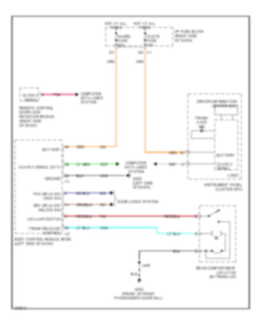 https://portal-diagnostov.com/license.html
Automotive Electricians Portal FZCO
Automotive Electricians Portal FZCO
https://portal-diagnostov.com/license.html
https://portal-diagnostov.com/license.html
Automotive Electricians Portal FZCO
Automotive Electricians Portal FZCOList of elements for Trunk Release Wiring Diagram for Buick Allure Super 2008:
- Battery
- Body control module (bcm) (left side of dash)
- Class 2
- Class 2 serial
- Class 2 serial data
- Clstr fuse 10a
- Computer data lines system
- Door locks system
- Driver information center (dic)
- Drv dr lk sw unlock sig
- E8 x1
- G200 (left side of dash)
- G302 (front of front passenger's door sill)
- Ground
- Hazrd fuse 20a
- Hot at all times
- I/p fuse block (right side of dash)
- Instrument panel cluster (ipc)
- J406
- Lid ajar switch
- Logic
- Pas dr lk sw unlk sig
- Pnk
- Rear compartment lid latch (in trunk lid)
- Remote control door lock receiver (rcdlr) (right side of dash)
- Serial
- Trunk ajar ind
- Trunk release control x2
WARNING SYSTEMS
Warning Systems Wiring Diagram (1 of 2) for Buick Allure Super 2008
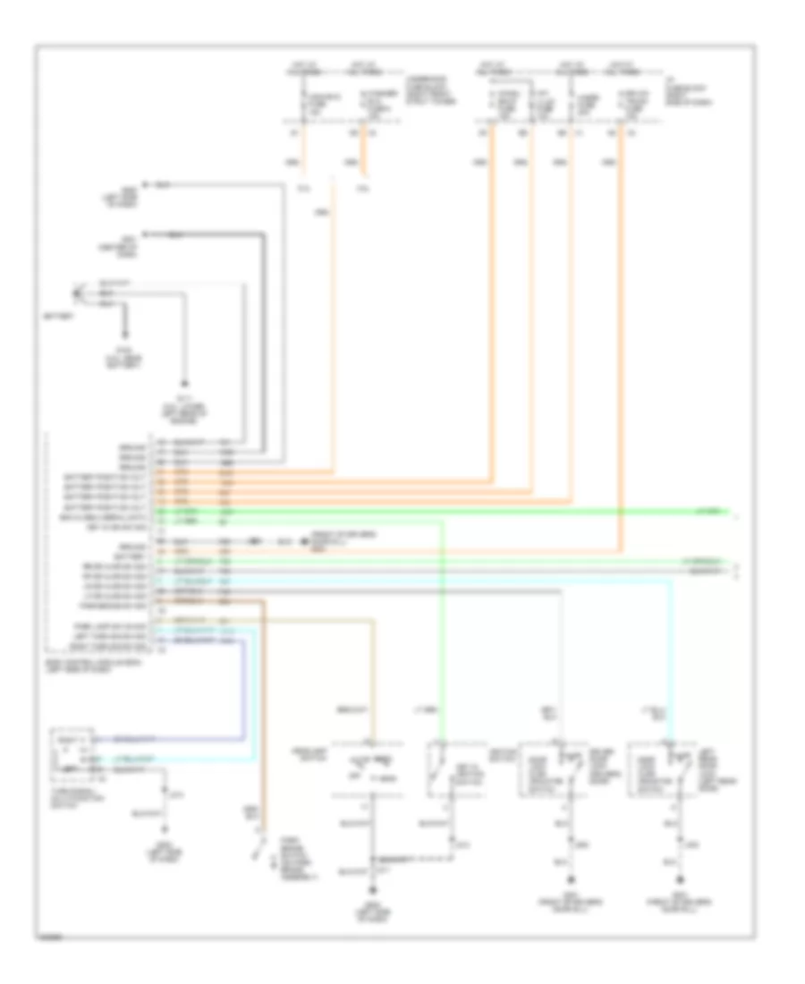 https://portal-diagnostov.com/license.html
Automotive Electricians Portal FZCO
Automotive Electricians Portal FZCO
https://portal-diagnostov.com/license.html
https://portal-diagnostov.com/license.html
Automotive Electricians Portal FZCO
Automotive Electricians Portal FZCOList of elements for Warning Systems Wiring Diagram (1 of 2) for Buick Allure Super 2008:
- (front of driver's door sill) g301
- 3.8l
- 5.3l
- Ajar
- Auto
- Battery
- Battery positive volt
- Bcm class 2 serial data
- Body control module (bcm) (left side of dash)
- Chmsl/ bkup fuse 15a
- Door lock ajar indicator switch
- Dr/lck trunk fuse 15a
- Driver door lock (driver's door)
- G102 (3.8l: near battery)
- G111 (3.8l: lower left rear of engine)
- G200 (left side of dash)
- G201 (center of dash)
- G202 (left side of dash)
- G301 (front of driver's door sill)
- Ground
- Hazrd fuse 20a
- Head
- Headlamp switch
- Hot at all times
- I/p fuse block (right side of dash)
- Ignition switch
- Int/ illum fuse 10a
- J214
- J303
- J500
- Key in ign sw sig
- Key in ignition switch
- Left
- Left rear door lock (left rear door)
- Left turn sig sw sig
- Lf dr ajar sw sig
- Lr dr ajar sw sig
- Off
- Park
- Park brake sw sig
- Park brake switch (on park brake assembly)
- Park lamp sw on sig
- Rf dr ajar sw sig
- Right
- Right turn sig sw sig
- Rr dr ajar sw sig
- Turn signal/ multi-function switch
- Underhood fuse block (right front strut tower)
- Washer/ rvc fuse 6 15a
- Wsw/rvc fuse 15a
Warning Systems Wiring Diagram (2 of 2) for Buick Allure Super 2008
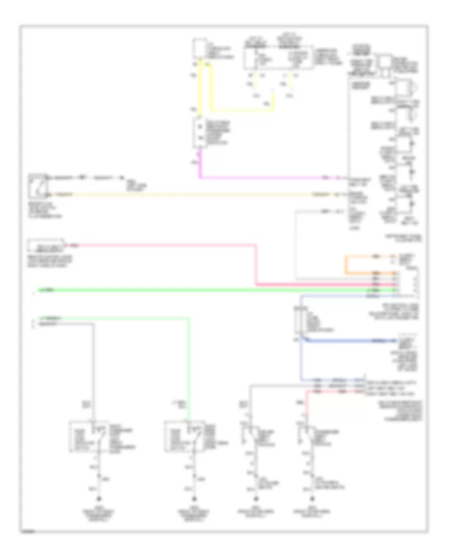 https://portal-diagnostov.com/license.html
Automotive Electricians Portal FZCO
Automotive Electricians Portal FZCO
https://portal-diagnostov.com/license.html
https://portal-diagnostov.com/license.html
Automotive Electricians Portal FZCO
Automotive Electricians Portal FZCOList of elements for Warning Systems Wiring Diagram (2 of 2) for Buick Allure Super 2008:
- (uplevel) message center
- 3.8l
- 5.3l
- A11
- A14
- A16
- Abs/tcs class 2 serial data
- Air bag/ display fuse 10a
- Ajar
- Bcm class 2 serial data
- Brake fluid level switch (on brake fluid reservoir)
- Brake ind
- Brake warning ind ctrl
- Check tire pressure service tire monitor
- Class 2
- Class 2 a1
- Digital radio receiver (if equipped) (left side of trunk)
- Door lock ajar indicator switch
- Driver information center (dic) (if equipped)
- Driver seat belt buckle
- Front passenger door lock (front passenger's door)
- G202 (left side of dash)
- G301 (front of driver's door sill)
- G302 (front of front passenger's door sill)
- Hot w/ ign 1 relay energized
- Hot w/ ignition main pcb relay energized
- I/p fuse block (right side of dash)
- Ign
- Inflatable restraint passenger air bag on/off indicator
- Inflatable restraint sensing & diagnostic module (sdm) (under front passenger's seat)
- Instrument panel cluster (ipc)
- Ipc class 2 serial data
- Ipc/bcm class 2 serial data
- J211
- J330 (w/ power seats)
- J333 (w/ power & heated seats)
- J406
- J604
- Left seat belt sw
- Left turn signal ind
- Logic
- Low tire pressure ind
- Message request
- Nca
- Pass seat belt ind
- Passenger seat belt buckle
- Pnk
- Radio
- Red
- Remote control door lock receiver (rcdlr) (right side of dash)
- Rfa class 2 serial data
- Right rear door lock (right rear door)
- Right seat belt sw sig
- Right turn signal ind
- Sdm class 2 serial data
- Seat belt ind
- Serial data
- Sir fuse 9 10a
- Splice pack jx205 (clipped to knee bolster panel, right of data link connector)
- Underhood fuse block (right front strut tower)
WIPER/WASHER
3.6L VIN 7
3.6L VIN 7, Wiper/Washer Wiring Diagram for Buick Allure Super 2008
 https://portal-diagnostov.com/license.html
Automotive Electricians Portal FZCO
Automotive Electricians Portal FZCO
https://portal-diagnostov.com/license.html
https://portal-diagnostov.com/license.html
Automotive Electricians Portal FZCO
Automotive Electricians Portal FZCOList of elements for 3.6L VIN 7, Wiper/Washer Wiring Diagram for Buick Allure Super 2008:
- 3.6l
- 3.8l
- A14
- A15
- B14
- B3 x1
- Battery
- Body control module (bcm) (behind left side of dash, left of steering column)
- C14
- C15
- Class 2 serial data
- D5 x3
- Delay switch
- Driver information center (dic)
- E14
- E15
- F10
- F11
- F12
- F14
- F6 x2
- G100 (in back of right headlight on frame)
- G113 (lower left front of engine, on transmission stud, near starter)
- G115 (mounted to bank 1 cylinder head above exhaust manifold)
- G14
- G15
- G200 (behind left side of dash knee bolster, at base of steering column)
- Ground
- High
- Hot at all times
- Ign
- Instrument panel cluster (ipc)
- Int
- J101
- J116
- J124
- J213
- Jx205 (clipped to knee bolster panel, right of data link connector)
- Logic
- Low
- Low wash indicator
- Low washer fluid ind sig
- Mist
- Off
- Park sw sig
- Park switch
- Pnk
- Red
- Tan
- Turn signal/ multifunction switch
- Underhood fuse block (mounted to right strut tower)
- Washer pump ctrl
- Washer switch
- Washer/ rvc fuse 6 15a
- Windshield washer fluid level switch (right side of engine compt, in washer fluid reservoir)
- Windshield washer fluid pump (on right side of engine compt, in washer fluid reservoir)
- Windshield washer sw sig x3
- Windshield wiper motor (on left side of firewall)
- Windshield wiper sw hi sig
- Windshield wiper sw high sig
- Windshield wiper sw low sig
- Windshield wiper switch
- Wiper hi relay
- Wiper relay
- Wiper rly ctrl
- Wiper/ ws fuse 5 25a
- X2 f4
3.8L VIN 2
3.8L VIN 2, Wiper/Washer Wiring Diagram for Buick Allure Super 2008
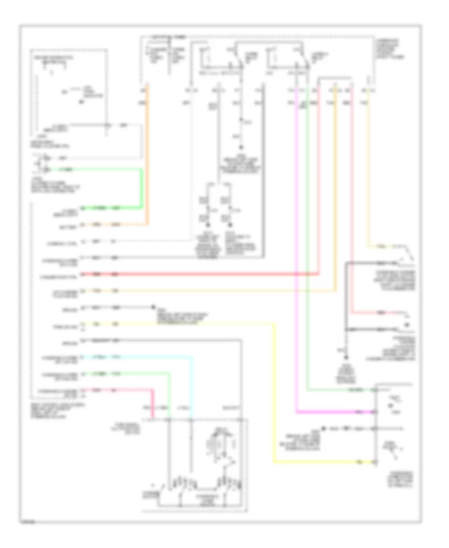 https://portal-diagnostov.com/license.html
Automotive Electricians Portal FZCO
Automotive Electricians Portal FZCO
https://portal-diagnostov.com/license.html
https://portal-diagnostov.com/license.html
Automotive Electricians Portal FZCO
Automotive Electricians Portal FZCOList of elements for 3.8L VIN 2, Wiper/Washer Wiring Diagram for Buick Allure Super 2008:
- 3.6l
- 3.8l
- A14
- A15
- B14
- B3 x1
- Battery
- Body control module (bcm) (behind left side of dash, left of steering column)
- C14
- C15
- Class 2 serial data
- D5 x3
- Delay switch
- Driver information center (dic)
- E14
- E15
- F10
- F11
- F12
- F14
- F6 x2
- G100 (in back of right headlight on frame)
- G113 (lower left front of engine, on transmission stud, near starter)
- G115 (mounted to bank 1 cylinder head above exhaust manifold)
- G14
- G15
- G200 (behind left side of dash knee bolster, at base of steering column)
- Ground
- High
- Hot at all times
- Ign
- Instrument panel cluster (ipc)
- Int
- J101
- J116
- J124
- J213
- Jx205 (clipped to knee bolster panel, right of data link connector)
- Logic
- Low
- Low wash indicator
- Low washer fluid ind sig
- Mist
- Off
- Park sw sig
- Park switch
- Pnk
- Red
- Tan
- Turn signal/ multifunction switch
- Underhood fuse block (mounted to right strut tower)
- Washer pump ctrl
- Washer switch
- Washer/ rvc fuse 6 15a
- Windshield washer fluid level switch (right side of engine compt, in washer fluid reservoir)
- Windshield washer fluid pump (on right side of engine compt, in washer fluid reservoir)
- Windshield washer sw sig x3
- Windshield wiper motor (on left side of firewall)
- Windshield wiper sw hi sig
- Windshield wiper sw high sig
- Windshield wiper sw low sig
- Windshield wiper switch
- Wiper hi relay
- Wiper relay
- Wiper rly ctrl
- Wiper/ ws fuse 5 25a
- X2 f4
5.3L VIN C
5.3L VIN C, Wiper/Washer Wiring Diagram for Buick Allure Super 2008
 https://portal-diagnostov.com/license.html
Automotive Electricians Portal FZCO
Automotive Electricians Portal FZCO
https://portal-diagnostov.com/license.html
https://portal-diagnostov.com/license.html
Automotive Electricians Portal FZCO
Automotive Electricians Portal FZCOList of elements for 5.3L VIN C, Wiper/Washer Wiring Diagram for Buick Allure Super 2008:
- A1 x2
- Battery
- Body control module (bcm) (behind left side of dash, left of steering column)
- C2 x1
- Class 2 serial data
- Delay switch
- Driver information center (dic)
- G100 (in back of right headlight on frame)
- G113 (lower left front of engine, on transmission stud, near starter)
- G200 (behind left side of dash knee bolster, at base of steering column)
- G201 (below dash, bolted to dash carrier)
- Ground
- High
- Hot at all times
- Ign
- Instrument panel cluster (ipc)
- Int
- J101
- J124
- Jx205 (clipped to knee bolster panel, right of data link connector)
- K3 x3
- Logic
- Low
- Low wash indicator
- Low washer fluid ind sig
- Mist
- Off
- Park sw sig
- Park switch
- Pnk
- Red
- Tan
- Turn signal/ multifunction switch
- Underhood fuse block (mounted to right strut tower)
- Washer pump ctrl
- Washer switch
- Windshield washer fluid level switch (right side of engine compt, in washer fluid reservoir)
- Windshield washer fluid pump (on right side of engine compt, in washer fluid reservoir)
- Windshield washer sw sig x3
- Windshield wiper motor (on left side of firewall)
- Windshield wiper sw hi sig
- Windshield wiper sw high sig
- Windshield wiper sw low sig
- Windshield wiper switch
- Wiper hi pcb relay
- Wiper pcb relay
- Wiper rly ctrl
- Wpr fuse 25a
- Wsw/ rvc fuse 15a
- X2 k4

 Čeština
 Dansk
Dansk Deutsch
 Ελληνικά
 English
 English
 Español
 Suomi
Suomi Français
 Français
 Hrvatski
 Magyar
 Italiano
 日本語
日本語 한국어
한국어 Nederlands
 Polski
 Português
 Português
 Română
 Русский
 Slovenčina
 Slovenščina
 Svenska
 Türkçe
 中文 (中国)
