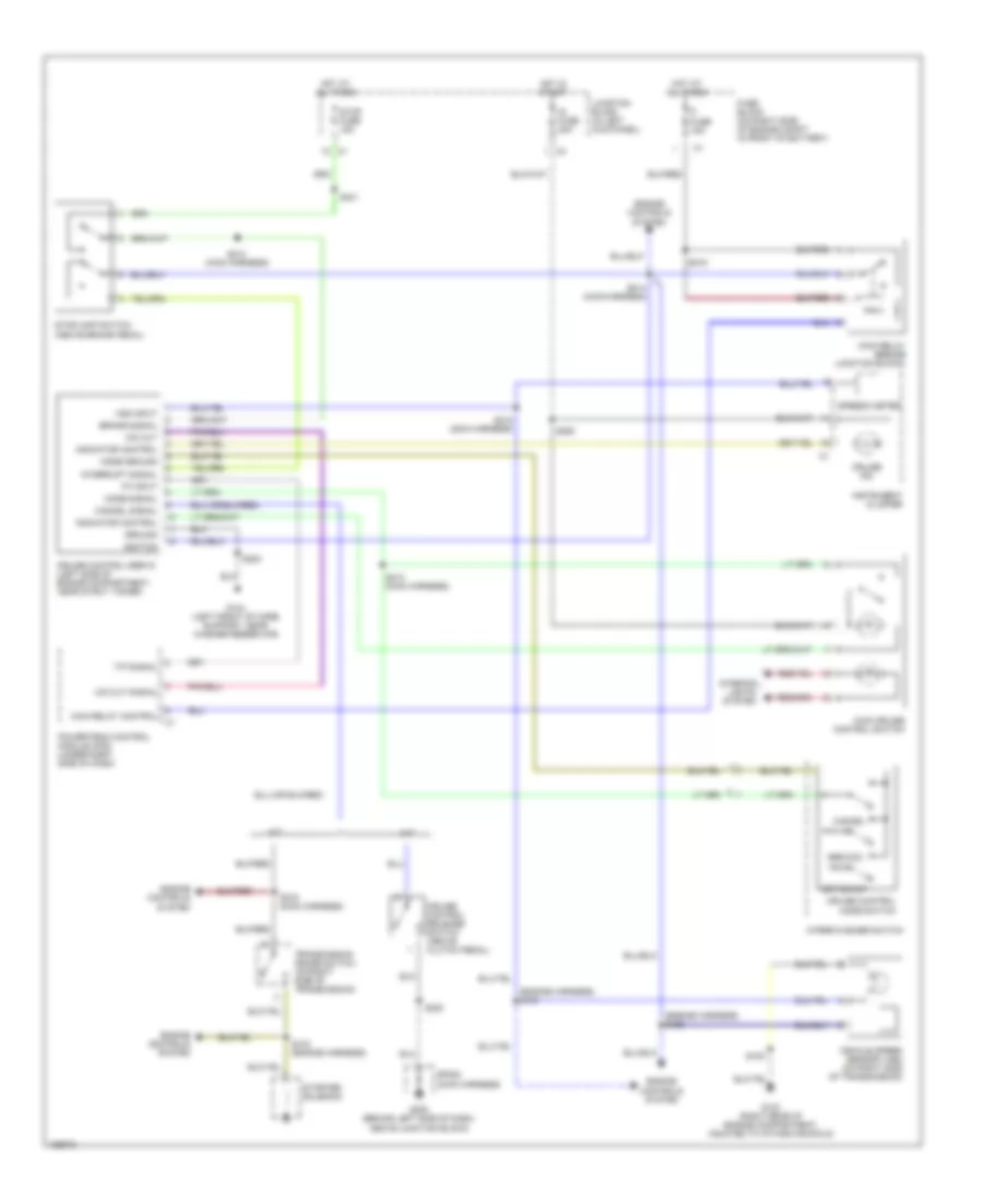
AIR CONDITIONING
Compressor Wiring Diagram for Chevrolet Tracker 2004
 https://portal-diagnostov.com/license.html
Automotive Electricians Portal FZCO
Automotive Electricians Portal FZCO
https://portal-diagnostov.com/license.html
https://portal-diagnostov.com/license.html
Automotive Electricians Portal FZCO
Automotive Electricians Portal FZCO
List of elements for Compressor Wiring Diagram for Chevrolet Tracker 2004:
- A/c compressor clutch
- A/c compressor control module (behind center of dash, on heater case)
- A/c compressor relay (on right side of engine compt, near battery)
- A/c fuse 25a
- Def fuse 15a
- Fuse block (on right side of engine compt, in front of battery)
- Hot at all times
- Hot in run
- Htr fuse 60a
- Junction block (in left kick panel)
- Pnk
- Red
- Relay ctrl
- S112 (a/c jumper harness)
- S113 (a/c jumper harness)
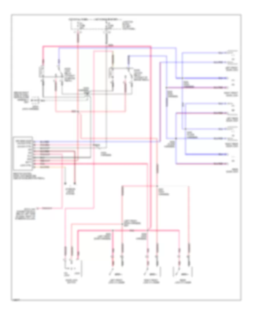
Manual A/C Wiring Diagram for Chevrolet Tracker 2004
 https://portal-diagnostov.com/license.html
Automotive Electricians Portal FZCO
Automotive Electricians Portal FZCO
https://portal-diagnostov.com/license.html
https://portal-diagnostov.com/license.html
Automotive Electricians Portal FZCO
Automotive Electricians Portal FZCOList of elements for Manual A/C Wiring Diagram for Chevrolet Tracker 2004:
- (engine harness) s106
- (i/p harness) s252
- A/c compressor clutch
- A/c compressor control module (behind center of dash, on heater case)
- A/c compressor relay (on right side of engine compt, near battery)
- A/c condenser fan (between radiator & grille)
- A/c condenser fan relay (on right side of engine compt, in) front of battery)
- A/c fuse 25a
- A/c refrigerant pressure switch (on right front of engine compt)
- A/c request
- A/c switch
- Blower fuse 30a
- Blower motor (behind right side of dash)
- Blower motor relay (behind right side of dash)
- Blower motor resistor (behind right side of dash, in blower case)
- Blower on
- Blower switch
- Cut-out ctrl
- Cut-out sig
- Def fuse 15a
- Defroster switch
- Ect in
- Engine controls system
- Engine coolant temperature (ect) sensor (on rear of left cylinder head)
- Evap temp in
- Fuse block (on right side of engine compt, in front of battery)
- G103 (right rear of engine compt, mounted to intake manifold)
- G105 (right front of core support, near horn)
- G201 (behind right side of dash, near blower assembly)
- Grd
- Hot at all times
- Hot in run
- Hot in run or start
- Htr fuse 60a
- Idle-up ctrl
- Idle-up sig
- Ig fuse 20a
- Ign
- Junction block (in left kick panel)
- Low
- Nca
- Off
- Pnk
- Powertrain control module (pcm) (under right side of dash)
- Press sig
- Red
- Rly ctrl
- S112 (a/c jumper harness)
- S113 (a/c jumper harness)
- S114 (a/c jumper harness)
- S203 (main harness)
- S204
- S205 (main harness)
- S206 (main harness)
- S207 (main harness)
- S208
- S250 (i/p harness)
- S263
- Sens grd
- Sp201 (main harness)
- Thermistor
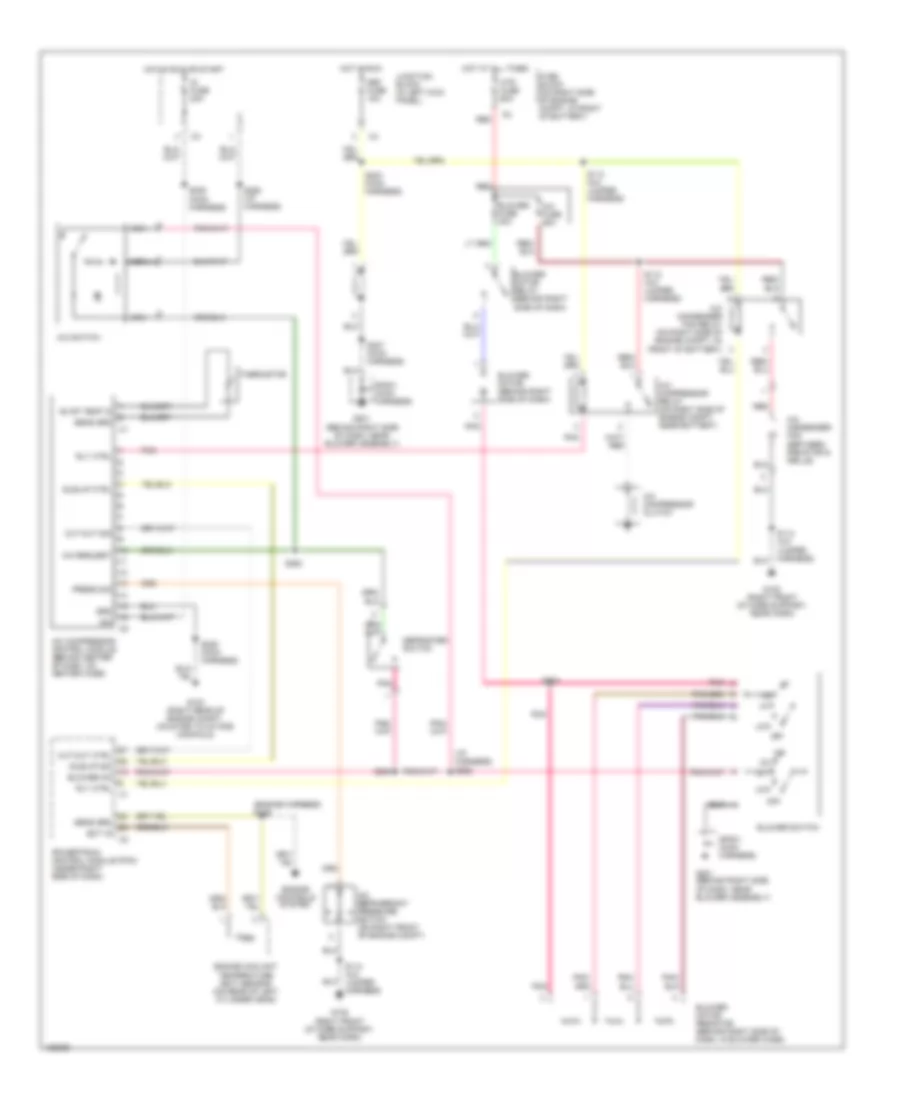
ANTI-LOCK BRAKES
Anti-lock Brakes Wiring Diagram for Chevrolet Tracker 2004
 https://portal-diagnostov.com/license.html
Automotive Electricians Portal FZCO
Automotive Electricians Portal FZCO
https://portal-diagnostov.com/license.html
https://portal-diagnostov.com/license.html
Automotive Electricians Portal FZCO
Automotive Electricians Portal FZCOList of elements for Anti-lock Brakes Wiring Diagram for Chevrolet Tracker 2004:
- (behind left side of dash, above junction block) g200
- (left front of core support, near washer reservoir) g104
- (m/t) (a/t)
- (main harness)
- (main harness) s213
- (under right side of dash) powertrain control module (pcm)
- 4wd ind
- 4wd signal
- A10
- A11
- Abs fuse 50a
- Abs ind
- Abs ind control
- Accelerometer (4wd) (under rear floor console)
- B10
- B11
- Battery
- Brake fluid level switch
- Brake ind
- Brake pressure modulator valve (bpmv)
- C10
- C11
- Connector (dlc) obd 2 (below left side of dash, right of steering column)
- Data link
- Daytime running lamps (drl) control module (behind top left side of dash, right of steering column)
- Def fuse 15a
- Electronic brake control module (ebcm) (at left rear corner of engine compartment)
- Electronic brake control relay
- Fuse block (on right side of engine compartment, in front of battery)
- Gnd
- Ground
- Hot at all times
- Hot in run or start
- Idle up signal
- Ig fuse 20a
- Ind ctrl
- Instrument cluster
- Junction block (in left kick panel)
- Lamp driver module
- Left front inlet valve solenoid
- Left front outlet solenoid valve
- Left front signal high
- Left front signal low
- Left front wheel speed sensor (on left front steering knuckle)
- Left rear signal high
- Left rear signal low
- Left rear wheel speed sensor (on left rear of axle housing)
- Nca
- Pump motor
- Right front inlet solenoid valve
- Right front outlet solenoid valve
- Right front signal high
- Right front signal low
- Right front wheel speed sensor (on right front steering knuckle)
- Right rear inlet solenoid valve
- Right rear outlet solenoid valve
- Right rear signal high
- Right rear signal low
- Right rear wheel speed sensor (on right rear of axle housing)
- S202
- S203
- S205
- S241
- S248
- S250
- S264
- S265
- S266
- Serial data line
- Signal
- Sp200
- Stop fuse 15a
- Stop lamp switch input
- Stoplamp switch (above brake pedal)
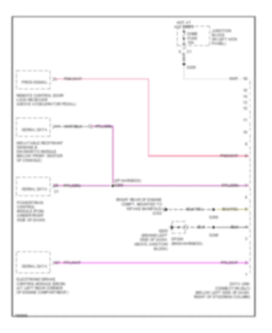
COMPUTER DATA LINES
Computer Data Lines Wiring Diagram for Chevrolet Tracker 2004
 https://portal-diagnostov.com/license.html
Automotive Electricians Portal FZCO
Automotive Electricians Portal FZCO
https://portal-diagnostov.com/license.html
https://portal-diagnostov.com/license.html
Automotive Electricians Portal FZCO
Automotive Electricians Portal FZCOList of elements for Computer Data Lines Wiring Diagram for Chevrolet Tracker 2004:
- (i/p harness) s260
- (right rear of engine compt, mounted to intake manifold) g103
- Data link connector (dlc) (below left side of dash, right of steering column)
- Dome fuse 10a
- Electronic brake control module (ebcm) (at left rear corner of engine compartment)
- G200 (behind left side of dash, above junction block)
- Hot at all times
- Inflatable restraint sensing & diagnostic module (below front center of console)
- Junction block (in left kick panel)
- Powertrain control module (pcm) (under right side of dash)
- Prog signal
- Remote control door lock receiver (above accelerator pedal)
- S248
- S255
- S266
- Serial data
- Sp200 (main harness)
CRUISE CONTROL
Cruise Control Wiring Diagram for Chevrolet Tracker 2004
 https://portal-diagnostov.com/license.html
Automotive Electricians Portal FZCO
Automotive Electricians Portal FZCO
https://portal-diagnostov.com/license.html
https://portal-diagnostov.com/license.html
Automotive Electricians Portal FZCO
Automotive Electricians Portal FZCOList of elements for Cruise Control Wiring Diagram for Chevrolet Tracker 2004:
- (engine harness) s102
- (engine harness) s104
- A/t
- Brake signal
- Cancel
- Cancel signal
- Cruise control mode switch
- Cruise control release switch (above clutch pedal)
- Cruise control servo (left side of engine compartment, near strut tower)
- Cruise ind
- Engine controls system
- Fi fuse 15a
- Fuse block (on right side of engine compt in front of battery)
- G103 (right rear of engine compartment, mounted to intake manifold)
- G104 (left front of core support, near washer reservoir)
- G200 (behind left side of dash, above junction block)
- Ground
- Hot at all times
- Hot in start
- Ig fuse 20a
- Ignition
- Indicator control
- Instrument cluster
- Interior lights system
- Interrupt signal
- Junction block (in left kick panel)
- M/t
- Main cruise control switch
- Main relay (beside junction block)
- Main relay control
- Mode ground
- Mode signal
- O/d cut
- O/d cut signal
- Powertrain control module (pcm) (under right side of dash)
- Res/acc
- S103 (engine harness)
- S108
- S200
- S202
- S212 (main harness)
- S213 (main harness)
- S214 (main harness)
- S215 (main harness)
- S216 (main harness)
- S219
- S241
- S250
- Set/coast
- Sp200 (main harness)
- Speedo meter
- Starter solenoid
- Stop fuse 15a
- Stoplamp switch (above brake pedal)
- T/p signal
- Tp input
- Transmission range switch (on right side of transmission)
- Vehicle speed sensor (vss) (on right side of transmission)
- Vss input
- Wiper/washer switch
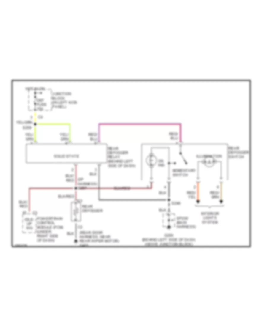
DEFOGGERS
Defoggers Wiring Diagram for Chevrolet Tracker 2004
 https://portal-diagnostov.com/license.html
Automotive Electricians Portal FZCO
Automotive Electricians Portal FZCO
https://portal-diagnostov.com/license.html
https://portal-diagnostov.com/license.html
Automotive Electricians Portal FZCO
Automotive Electricians Portal FZCOList of elements for Defoggers Wiring Diagram for Chevrolet Tracker 2004:
- (i/p harness) s257
- (rear door harness, near rear wiper motor) g401
- Def fuse 15a
- G200 (behind left side of dash, above junction block)
- Hot in on
- Idle- up sig
- Illumination
- Interior lights system
- Junction block (in left kick panel)
- Momentary switch
- On ind
- Powertrain control module (pcm) (under right side of dash)
- Rear defogger
- Rear defogger relay (behind left side of dash)
- Rear defogger switch
- S248
- S259
- Solid state
- Sp200 (main harness)
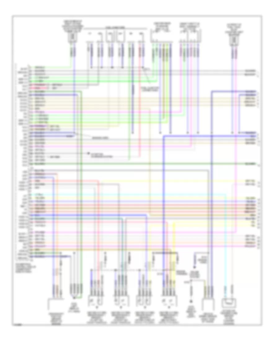
ENGINE PERFORMANCE
2.5L VIN 4
2.5L VIN 4, Engine Performance Wiring Diagram (1 of 3) for Chevrolet Tracker 2004
 https://portal-diagnostov.com/license.html
Automotive Electricians Portal FZCO
Automotive Electricians Portal FZCO
https://portal-diagnostov.com/license.html
https://portal-diagnostov.com/license.html
Automotive Electricians Portal FZCO
Automotive Electricians Portal FZCOList of elements for 2.5L VIN 4, Engine Performance Wiring Diagram (1 of 3) for Chevrolet Tracker 2004:
- (above rear of right intake manifold runner) evap canister purge valve
- (center rear
- (engine harn)
- (engine harness)
- (fuel injector jumper harn)
- (in front of fuel tank) evap canister vent solenoid
- (near throttle
- Body assembly) iac valve
- Ckp
- Cmp
- Crankshaft position sensor (front of engine)
- Crk
- Cruise control system
- Dlc
- Ect
- Egr va
- Evap
- Evap v
- Fuel injectors
- G102 (left rear of cyl head)
- G103 (right rear of eng compt)
- Ground
- Heated oxygen sensor bank 1 sensor 1 (in left ex- haust manifold)
- Heated oxygen sensor bank 1 sensor 2 (after warm-up catalytic conv)
- Heated oxygen sensor bank 2 sensor 1 (in right ex- haust manifold)
- Heated oxygen sensor bank 2 sensor 2 (below right catalytic conv)
- Ho2s 11
- Ho2s 12
- Ho2s 21
- Ho2s 22
- Iac
- Iat
- Ig co1
- Ig co2
- Ig co3
- Ig co4
- Ig co5
- Ig co6
- Ign
- Inj1
- Inj2
- Inj3
- Inj4
- Inj5
- Inj6
- Intake air temperature sensor (in air cleaner housing)
- Maf
- Map
- Nca
- Of engine) egr valve
- Pnk
- Powertrain control module (under right side of dash)
- Red
- Ref v
- S102
- S104 (engine harn)
- S107
- S108
- S111
- S116
- Sens g
- Starting/ charging system
- Vehicle speed sensor (right side of trans)
- Vss
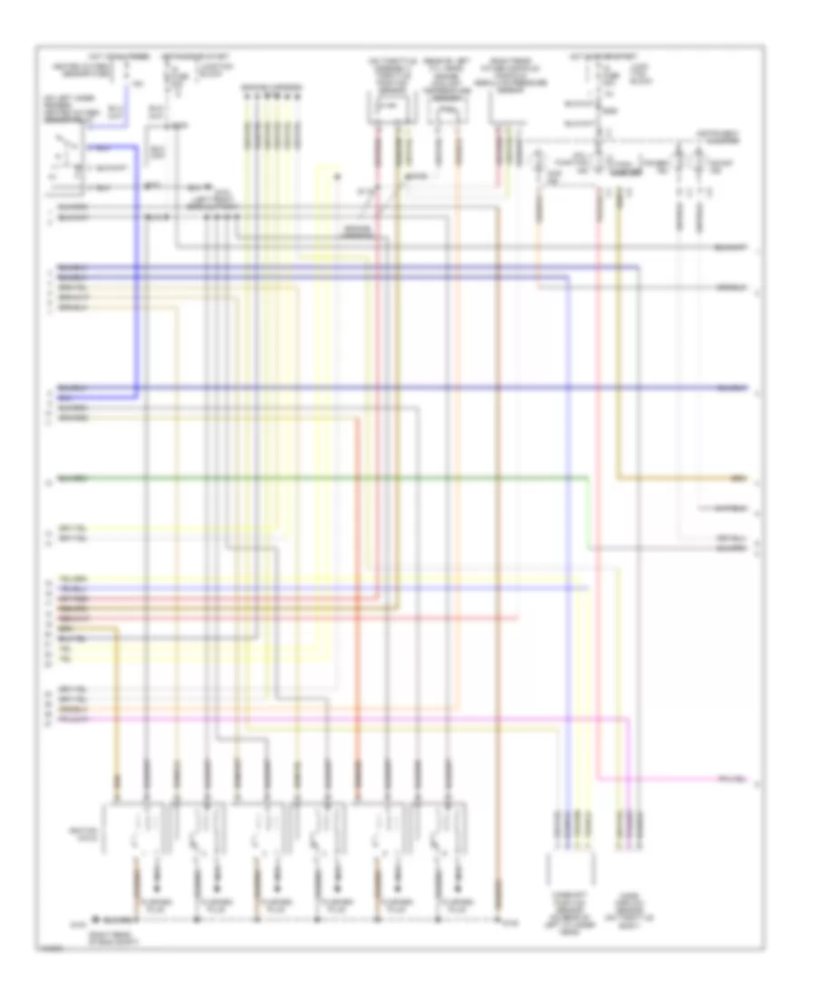
2.5L VIN 4, Engine Performance Wiring Diagram (2 of 3) for Chevrolet Tracker 2004
 https://portal-diagnostov.com/license.html
Automotive Electricians Portal FZCO
Automotive Electricians Portal FZCO
https://portal-diagnostov.com/license.html
https://portal-diagnostov.com/license.html
Automotive Electricians Portal FZCO
Automotive Electricians Portal FZCOList of elements for 2.5L VIN 4, Engine Performance Wiring Diagram (2 of 3) for Chevrolet Tracker 2004:
- (engine harness)
- (engine harness) s115
- (on left inner fender) heated oxygen sensor relay
- (on throttle assembly) throttle position sensor
- (rear of left cyl head) engine coolant temperature sensor
- (right rear intake manifold) manifold absolute pressure sensor
- (right rear of eng compt)
- 15a
- 4wd ind
- Camshaft position sensor (on rear of left cylinder head)
- G103
- G104 (left front core support)
- Heated oxygen sensor fuse
- Hot at all times
- Hot in on or start
- Ig fuse 20a
- Ignition coils
- Instrument cluster
- Junc- tion block
- Junction block
- Mal- function ind
- Mass airflow sensor (on throttle body)
- Nca
- Od/off ind
- Power ind
- S101
- S105
- S106
- S117
- S202
- S205
- S250
- Tach- ometer
- To spark plug
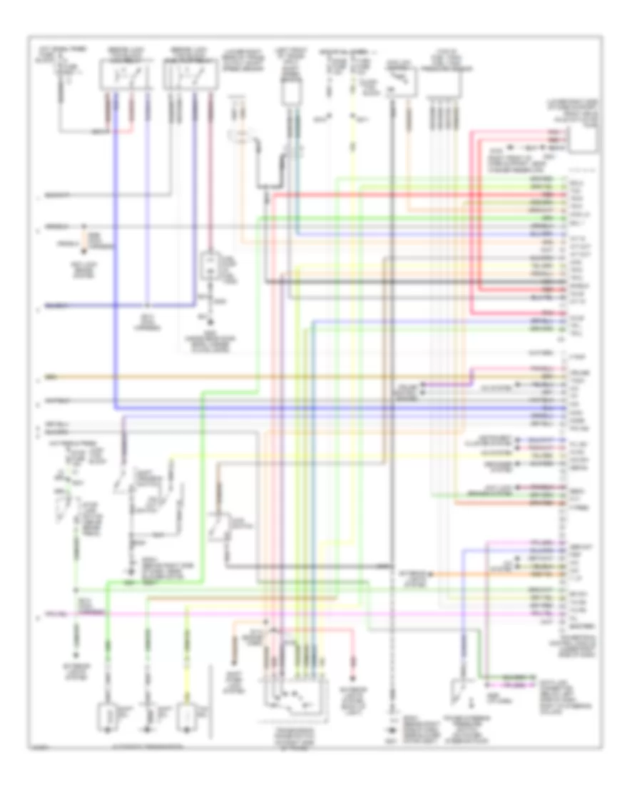
2.5L VIN 4, Engine Performance Wiring Diagram (3 of 3) for Chevrolet Tracker 2004
 https://portal-diagnostov.com/license.html
Automotive Electricians Portal FZCO
Automotive Electricians Portal FZCO
https://portal-diagnostov.com/license.html
https://portal-diagnostov.com/license.html
Automotive Electricians Portal FZCO
Automotive Electricians Portal FZCOList of elements for 2.5L VIN 4, Engine Performance Wiring Diagram (3 of 3) for Chevrolet Tracker 2004:
- (beside junc- tion block) fuel pump relay
- (beside junc- tion block) main relay
- (left front of trans) input shaft speed sensor
- (lower right rear of trans) output shaft speed sensor
- (lower right side of core support) front drive axle actuator pump
- (right front of core support, near washer reservoir)
- (top of fuel tank) fuel tank pressure sensor
- 4wd
- 4wd lo
- 4wd low switch
- 4wd switch
- A/c
- A/c system
- A/t in
- A/t out
- Anti-lock brake system
- Anti-lock brakes system
- Automatic transmission
- Axle
- Battery
- Bk sw
- C1 junc- tion block
- Cruise
- Cruise control system
- Data link connector (below left side of dash, right of steering column)
- Defog
- Defogger system
- Dome fuse 10a
- Ebcm
- Exterior lights system
- Exterior lights system (back up light)
- F pmp
- F pres
- Fi fuse 15a
- Fu lev
- Fuel pump (in fuel tank)
- Fuse block
- Fvt
- G105
- G201
- G400 (inside rear door, near license plate lamps)
- Hot at all times
- Hvac
- Instrument cluster system
- Junc- tion block
- Main
- Mil
- Mode
- Nca
- O/d
- O/d cut switch
- O/d sw
- Off
- P/n ind
- Pnk
- Power steering pressure switch (on power steering pump)
- Powertrain control module (under right side of dash)
- Psp
- Red
- S100
- S109
- S110 (engine harn)
- S201
- S211
- S213 (main harness)
- S214 (main harness)
- S218
- S219
- S220
- S241
- S260 (i/p harn)
- S266 (main harness)
- S300
- Ser dat
- Shield
- Shift inter- lock system
- Shift program switch
- Shift sol
- Sol 1
- Sol2
- Sp201 (behind right side of dash, near blower motor assy)
- Stop fuse 15a
- Stop- lamp switch (above brake pedal)
- T lp
- Tach
- Tcc
- Tcc sol
- Tk pr
- Tr 2
- Tr d
- Tr l
- Tr n
- Tr p
- Tr r
- Transmission range switch (on right side of trans)
- Turn fuse 10a
EXTERIOR LIGHTS
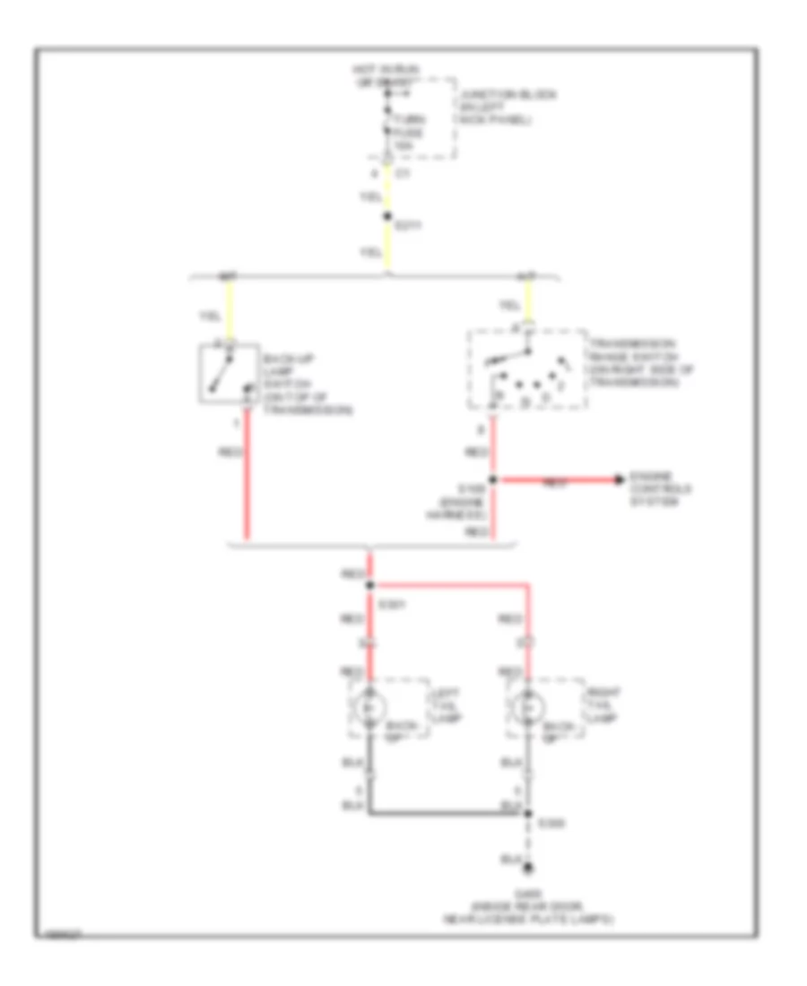
Back-up Lamps Wiring Diagram for Chevrolet Tracker 2004
 https://portal-diagnostov.com/license.html
Automotive Electricians Portal FZCO
Automotive Electricians Portal FZCO
https://portal-diagnostov.com/license.html
https://portal-diagnostov.com/license.html
Automotive Electricians Portal FZCO
Automotive Electricians Portal FZCOList of elements for Back-up Lamps Wiring Diagram for Chevrolet Tracker 2004:
- A/t
- Back- up
- Back-up lamp switch (on top of transmission)
- Engine controls system
- G400 (inside rear door, near license plate lamps)
- Hot in run or start
- Junction block (in left kick panel)
- Left tail lamp
- M/t
- Red
- Right tail lamp
- S109 (engine harness)
- S211
- S300
- S301
- Transmission range switch (on right side of transmission)
- Turn fuse 10a
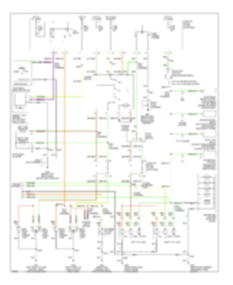
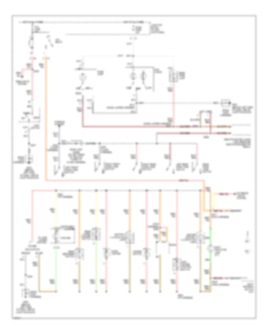
Exterior Lamps Wiring Diagram for Chevrolet Tracker 2004
 https://portal-diagnostov.com/license.html
Automotive Electricians Portal FZCO
Automotive Electricians Portal FZCO
https://portal-diagnostov.com/license.html
https://portal-diagnostov.com/license.html
Automotive Electricians Portal FZCO
Automotive Electricians Portal FZCOList of elements for Exterior Lamps Wiring Diagram for Chevrolet Tracker 2004:
- (a/t, m/t w/ cruise control)
- (floor harness)
- (floor harness) s306
- (m/t w/o cruise control)
- 4 door
- A/t
- A/t w/ cruise
- Ambient light sensor (on top right side of dash)
- Center high mounted stoplamp (chmsl)
- Cruise control servo (left side of engine compartment, near strut tower)
- Def fuse 15a
- Electronic brake control module (ebcm) (at left rear corner of engine compartment)
- G104 (left front of core support, near washer reservoir)
- G105 (right front of core support, near horn)
- G200 (behind left side of dash, above junction block)
- G201 (behind right side of dash, near blower assembly)
- G400 (inside rear door, near license plate lamps)
- G401 (rear door harness, near rear wiper motor)
- Haz fuse 15a
- Hazard switch
- Head
- Hot at all times
- Hot in run
- Hot in run or start
- Instrument cluster
- Interior lights system
- Junction block (in left kick panel)
- Left front side marker lamp
- Left front turn signal lamp
- Left tail lamp
- Left turn indicator
- License plate lamp
- Light switch
- Off
- Park
- Powertrain control module (pcm) (under right side of dash)
- Right front side marker lamp
- Right front turn signal lamp
- Right tail lamp
- Right turn indicator
- S201
- S202
- S207
- S211
- S213 (main harness)
- S217 (main harness)
- S239 (main harness)
- S241
- S247 (main harness)
- S248
- S253 (i/p harness)
- S259
- S261 (i/p harness)
- S262 (i/p harness)
- S300
- S304 (floor harness)
- S305 (floor harness)
- S307
- S400
- Shift lock relay (on right side of engine compartment, in front of battery)
- Sp200 (main harness)
- Sp201 (main harness)
- Stop
- Stop fuse 15a
- Stoplamp switch (above brake pedal)
- Tail
- Tail fuse 15a
- Tail relay
- Trailer harness
- Turn
- Turn fuse 10a
- Turn signal switch
- Turn signal/ headlamp switch
- Turn/ hazard flasher
- W/ abs
- W/ cruise control
GROUND DISTRIBUTION
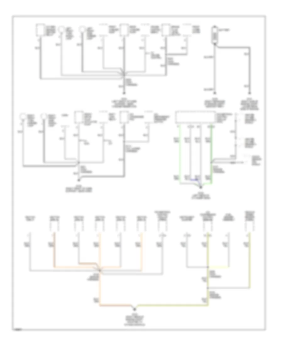
Ground Distribution Wiring Diagram (1 of 3) for Chevrolet Tracker 2004
 https://portal-diagnostov.com/license.html
Automotive Electricians Portal FZCO
Automotive Electricians Portal FZCO
https://portal-diagnostov.com/license.html
https://portal-diagnostov.com/license.html
Automotive Electricians Portal FZCO
Automotive Electricians Portal FZCOList of elements for Ground Distribution Wiring Diagram (1 of 3) for Chevrolet Tracker 2004:
- A/c compressor control module
- A/c condenser fan
- A/c refrigerant pressure switch
- Battery
- Brake fluid level switch
- Cruise control servo
- Front drive axle actuator pump
- Front washer pump
- Front wiper motor
- Fuel sender assembly
- G100 (right rear side of engine compt, near battery)
- G101 (right side of engine compt, lower rear side of engine)
- G102 (left rear of cylinder head)
- G103 (right rear of engine compt, mounted to intake manifold)
- G104 (left front of core support, near washer reservoir)
- G105 (right front of core support, near horn)
- Heated oxygen sensor 2 shield
- Horn
- Ignition coil 1
- Ignition coil 2
- Ignition coil 3
- Ignition coil 4
- Ignition coil 5
- Ignition coil 6
- Instrument cluster
- Knock sensor (ks) shield
- Left front side marker lamp
- Left front turn signal lamp
- Nca
- Oxygen sensor heater relay
- Powertrain control module (pcm)
- Rear washer pump
- Right front side signal lamp
- Right front turn marker lamp
- S105 (engine harness)
- S107 (engine harness)
- S108 (engine harness)
- S114 (a/c jumper harness)
- S201 (main harness)
- S202 (main harness)
- S206 (main harness)
- S232 (main harness)
- Shift lock relay
- Vehicle speed sensor (vss)
- W/ 4wd
- W/ a/t
- W/ cruise control
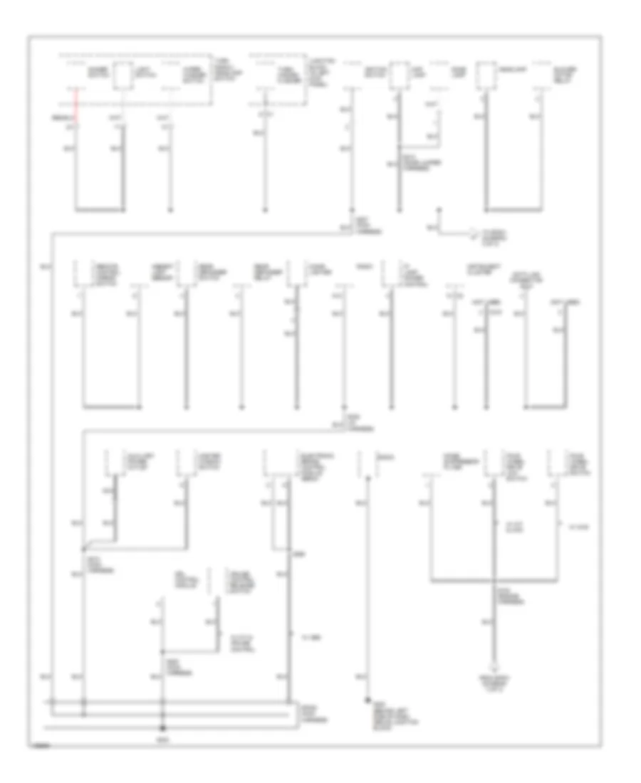
Ground Distribution Wiring Diagram (2 of 3) for Chevrolet Tracker 2004
 https://portal-diagnostov.com/license.html
Automotive Electricians Portal FZCO
Automotive Electricians Portal FZCO
https://portal-diagnostov.com/license.html
https://portal-diagnostov.com/license.html
Automotive Electricians Portal FZCO
Automotive Electricians Portal FZCOList of elements for Ground Distribution Wiring Diagram (2 of 3) for Chevrolet Tracker 2004:
- (not used)
- A12
- Ambient light sensor
- Auxiliary power outlet
- Blower motor relay
- C215
- Cigar lighter
- Cruise control release switch
- Data link connector (dlc)
- Dimmer switch
- Dome lamp
- Drl control module
- Electronic brake control module (ebcm)
- Four wheel drive low switch
- Four wheel drive switch
- From sp201 (diagram 3 of 3)
- G200
- G200 (behind left side of dash, above junction block)
- Harness)
- Headlamp
- Ignition switch
- Instrument cluster
- Ip lamp dimmer control
- Junction block (in left kick panel)
- Light switch
- Map lamp
- Master window switch
- Nca
- Noise suppressor filter
- Radio
- Rear defogger relay
- Rear defogger switch
- Remote control mirror switch
- S100 (engine harness)
- S200 (main harness)
- S210 (main harness)
- S265
- Sp200 (main harness)
- To sp201 (diagram 3 of 3)
- Turn signal/ headlamp switch
- Turn/ hazard flasher
- W/ 4wd
- W/ a/t & 4wd
- W/ abs
- W/ m/t & cruise control
- Wiper/ washer switch
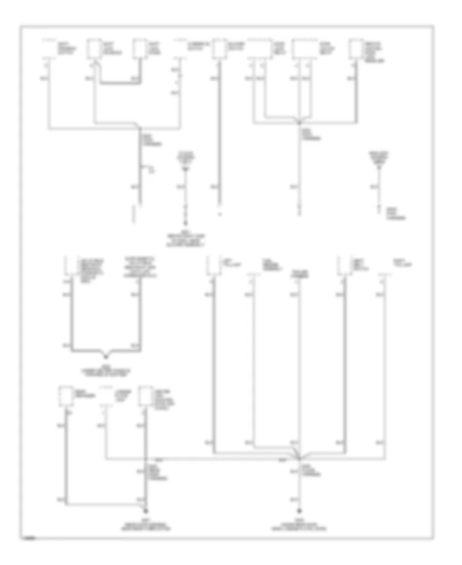
Ground Distribution Wiring Diagram (3 of 3) for Chevrolet Tracker 2004
 https://portal-diagnostov.com/license.html
Automotive Electricians Portal FZCO
Automotive Electricians Portal FZCO
https://portal-diagnostov.com/license.html
https://portal-diagnostov.com/license.html
Automotive Electricians Portal FZCO
Automotive Electricians Portal FZCOList of elements for Ground Distribution Wiring Diagram (3 of 3) for Chevrolet Tracker 2004:
- A18
- Blower switch
- Center high mounted stoplamp (chmsl)
- Door harness)
- Door lock relay
- Door unlock relay
- From s207 (diagram 2 of 3)
- Fuel sender assembly
- G201 (behind right side of dash, near blower assembly)
- G202 (under center console, forward of shifter)
- G400 (inside rear door, near license plate lamps)
- G401 (rear door harness, near rear wiper motor)
- Harness)
- Inflatable restraint sensing & diagnostic module (sdm)
- Left taillamp
- License plate lamp
- Overdrive switch
- Rear defogger
- Remote control door lock receiver
- Right taillamp
- S220 (main harness)
- S223 (main harness)
- Seat belt switch
- Shift lock diode
- Shift lock solenoid
- Shift program switch
- Sp201 (main harness)
- To s100 (diagram 2 of 3)
- Trailer harness
- W/ a/t
HEADLIGHTS
Headlights Wiring Diagram for Chevrolet Tracker 2004
 https://portal-diagnostov.com/license.html
Automotive Electricians Portal FZCO
Automotive Electricians Portal FZCO
https://portal-diagnostov.com/license.html
https://portal-diagnostov.com/license.html
Automotive Electricians Portal FZCO
Automotive Electricians Portal FZCOList of elements for Headlights Wiring Diagram for Chevrolet Tracker 2004:
- (main harness) s237
- Ambient light sensor (on top right side of dash)
- Anti-lock brakes system
- Battery
- Brake ind
- Charge sig
- Daytime running lamps (drl) control module (behind top left side of dash, right of steering column)
- Daytime running lamps diode (above blower motor, taped to main harness)
- Def fuse 15a
- Dimmer switch
- Dome fuse 10a
- Drl control
- Exterior lights system
- Fuse block (on right side of engine compartment, in front of battery)
- G200 (behind left side of dash, above junction block)
- Generator
- Ground
- H/l l fuse 15a
- H/l r fuse 15a
- Head
- Headlamp relay (above junction block)
- Headlamp sig
- High
- High beam ind
- Hot at all times
- Hot in run
- Hot in run or start
- Ig fuse 20a
- Ignition
- Ignition switch
- Instrument cluster
- Junction block (in left kick panel)
- Key-in sig
- Key-in switch
- Left headlamp
- Light switch
- Low
- Off
- Park
- Parking brake switch (on base of park brake lever)
- Pass
- Power distribution system
- Prk brk ind
- Red
- Right headlamp
- S200
- S205
- S207
- S218
- S233 (main harness)
- S234 (main harness)
- S235
- S236
- S238 (main harness)
- S240 (main harness)
- S248
- S259
- S268 (main harness)
- Sp200 (main harness)
- Starting/ charging system
- Turn signal/ headlamp switch
HORN
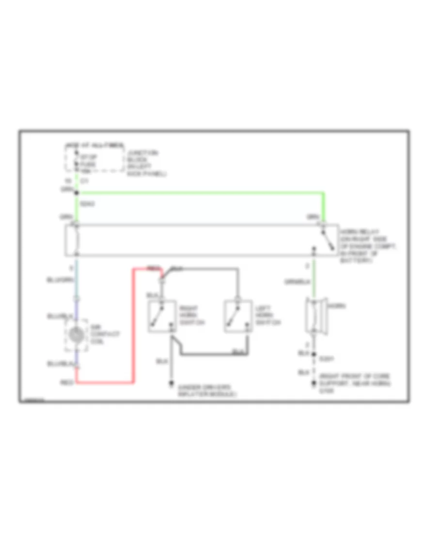
Horn Wiring Diagram for Chevrolet Tracker 2004
 https://portal-diagnostov.com/license.html
Automotive Electricians Portal FZCO
Automotive Electricians Portal FZCO
https://portal-diagnostov.com/license.html
https://portal-diagnostov.com/license.html
Automotive Electricians Portal FZCO
Automotive Electricians Portal FZCOList of elements for Horn Wiring Diagram for Chevrolet Tracker 2004:
- (right front of core support, near horn) g105
- (under driver's inflater module)
- Horn
- Horn relay (on right side of engine compt, in front of battery)
- Hot at all times
- Junction block (in left kick panel)
- Left horn switch
- Red
- Right horn switch
- S201
- S242
- Sir contact coil
- Stop fuse 15a
INSTRUMENT CLUSTER
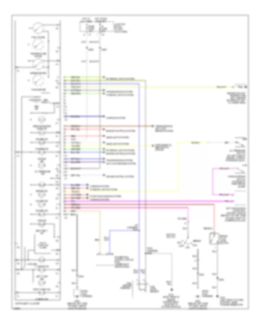
Instrument Cluster Wiring Diagram for Chevrolet Tracker 2004
 https://portal-diagnostov.com/license.html
Automotive Electricians Portal FZCO
Automotive Electricians Portal FZCO
https://portal-diagnostov.com/license.html
https://portal-diagnostov.com/license.html
Automotive Electricians Portal FZCO
Automotive Electricians Portal FZCOList of elements for Instrument Cluster Wiring Diagram for Chevrolet Tracker 2004:
- (4 bulbs)
- (i/p harness) s258
- (main harness) s206
- 4wd ind
- Abs circuit
- Abs ind
- Acc
- Air bag ind
- Anti-lock brakes system
- Brake fluid level switch
- Brake ind
- Charge ind
- Cruise control system
- Cruise ind
- Daytime running lamps (drl) control module (behind top left side of dash, right of steering column)
- Dome fuse 10a
- Engine controls system
- Engine coolant temperature (ect) sensor (on rear of left cylinder head)
- Exterior lights system
- Fuel gauge
- Fuel level sensor
- Fuel sender assembly
- G103 (right rear of engine compartment, mounted to intake manifold)
- G104 (left front of core support, near washer reservoir)
- G200 (behind left side of dash, above junction block)
- Headlights system
- Hi beam ind
- Hot at all times
- Hot in run or start
- Ig fuse 20a
- Ignition switch
- Illumination
- Instrument cluster
- Interior lights system
- Junction block (in left kick panel)
- Left turn ind
- Lock
- Multi- function alarm
- O/d off ind
- Off
- Oil pressure ind
- Oil pressure switch (on left side of engine, in front of engine mount)
- Parking brake switch (on base of park brake lever)
- Power ind
- Powertrain control module (pcm) (under right side of dash)
- Red
- Right turn ind
- Run
- S202
- S207
- S248
- S250
- S255
- Seat belt ind
- Service engine soon ind
- Sp200 (main harness)
- Speedometer
- Start
- Starting/charging system
- Tachometer
- Temperature gauge
- Transmissions system
- Transmissions, anti-lock brake systems
- Warning system
INTERIOR LIGHTS
Interior Lights Wiring Diagram for Chevrolet Tracker 2004
 https://portal-diagnostov.com/license.html
Automotive Electricians Portal FZCO
Automotive Electricians Portal FZCO
https://portal-diagnostov.com/license.html
https://portal-diagnostov.com/license.html
Automotive Electricians Portal FZCO
Automotive Electricians Portal FZCOList of elements for Interior Lights Wiring Diagram for Chevrolet Tracker 2004:
- (3 bulbs)
- (dome jumper harness)
- (dome jumper harness) s312
- (main harness) s268
- (not used)
- Ashtray illumination lamp
- B12
- Bulbs
- Cigar lighter
- Dome fuse 10a
- Dome lamp
- Dome lamp diode (on left rear of vehicle, taped to floor harness)
- Door
- Exterior lights system
- G200 (behind left side of dash, above junction block)
- Ground
- Hazard switch
- Head
- Headlights system
- Heater control illumination lamp
- Hot at all times
- I/p lamp dimmer control
- Instrument cluster
- Junction block (in left kick panel)
- Left front door jamb switch
- Left rear door jamb switch
- Light switch
- Main cruise control switch
- Map lamps
- Off
- Park
- Power
- Radio
- Rear defogger switch
- Rear dome lamp
- Rear door jamb switch
- Rear wiper/ washer switch
- Remote control door lock receiver (above accelerator pedal)
- Right front door jamb switch
- Right rear door jamb switch
- S207
- S239
- S246 (main harness)
- S248
- S253 (i/p harness)
- S254 (i/p harness)
- S269
- S270
- S302 (floor harness)
- S303 (floor harness)
- S311
- S313
- Shift indicator lamp (a/t)
- Shift program switch (a/t)
- Solid state
- Sp200 (main harness)
- Tail fuse 15a
- Tail relay
- Warning system
POWER DISTRIBUTION
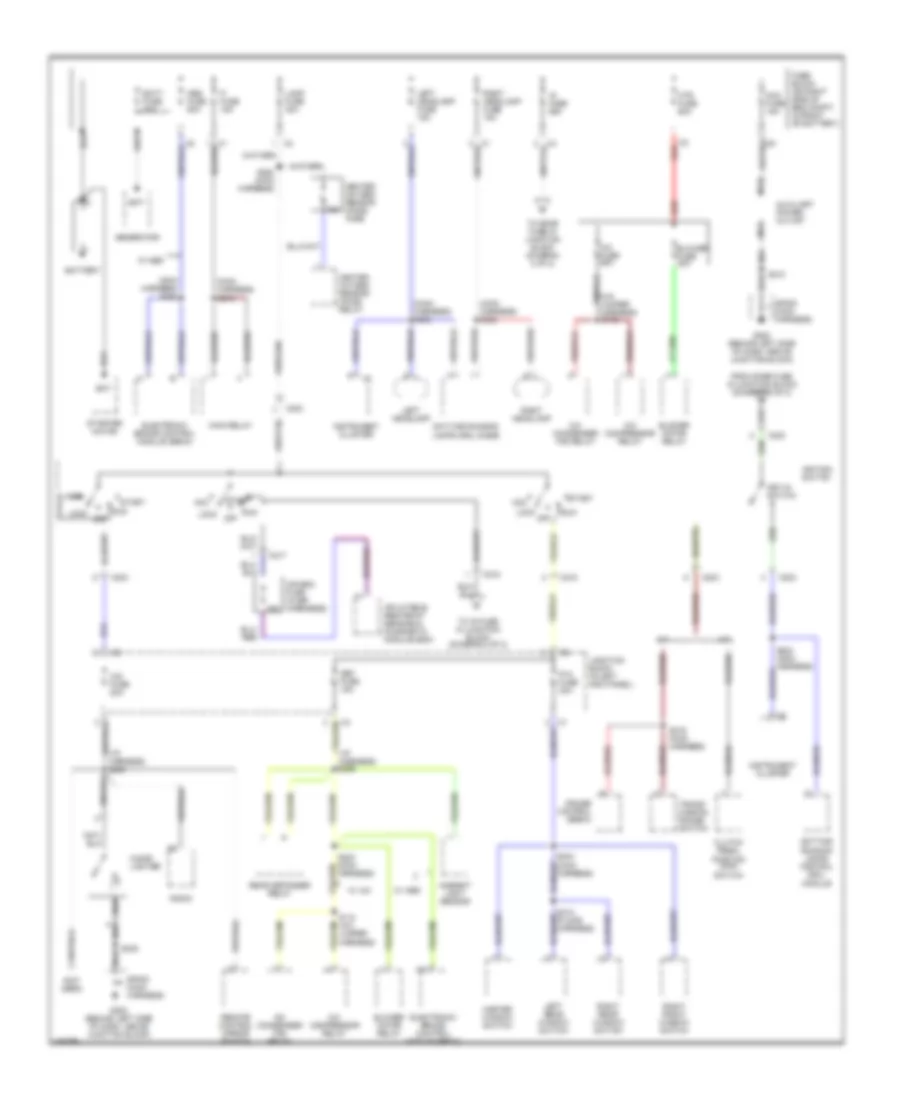
Power Distribution Wiring Diagram (1 of 2) for Chevrolet Tracker 2004
 https://portal-diagnostov.com/license.html
Automotive Electricians Portal FZCO
Automotive Electricians Portal FZCO
https://portal-diagnostov.com/license.html
https://portal-diagnostov.com/license.html
Automotive Electricians Portal FZCO
Automotive Electricians Portal FZCOList of elements for Power Distribution Wiring Diagram (1 of 2) for Chevrolet Tracker 2004:
- (i/p harness) s256
- (i/p harness) s259
- (main harness) s219
- (main harness) s235
- (main harness) s236
- (main harness) s264
- (not used)
- 15a
- A/c compressor relay
- A/c condenser fan relay
- A/c fuse 25a
- A/t
- A11
- Abs fuse 50a
- Acc
- Acc fuse 15a
- Air bag fuse (in sir harnness)
- Ambient light sensor
- Auxiliary power outlet
- Bat
- Batt fuse 80a
- Battery
- Blower fuse 30a
- Blower motor relay
- C2 red
- C203
- C217
- C218
- Cig fuse 20a
- Cigar lighter
- Clutch pedal position (cpp) switch
- Cruise control servo
- Daytime running lamps (drl) diode
- Daytime running lamps control (drl) module
- Def fuse 15a
- Electronic brake control module (ebcm)
- Fi fuse 15a
- Fuse block (on right side of eng compt, in front of battery)
- G200 (behind left side of dash, above junction block)
- Generator
- Harness)
- Heated oxygen sensor (ho2s) fuse
- Heated oxygen sensor (ho2s) relay
- Htr fuse 60a
- Ig fuse 60a
- Ignition switch
- Inflatable restraint sensing & diagnostic module (sdm)
- Instrument cluster
- Junction block (in left kick panel)
- Key-in switch
- Lamp fuse 30a
- Left headlamp
- Left headlamp fuse 15a
- Left rear window switch
- Lock
- M/t
- Main relay
- Master window switch
- Nca
- Off
- P/w fuse 30a
- Radio
- Rear defogger relay
- Red
- Remote control mirror switch
- Right front window switch
- Right headlamp
- Right headlamp fuse 15a
- Right rear window switch
- Run
- S210
- S216 (main harness)
- S248
- S264 (main harness)
- Sp200 (main harness)
- Start
- Starter motor
- To dome fuse in junction block (diagram 2 of 2)
- To ig fuse in junction block (diagram 2 of 2)
- Trans- mission range switch
- W/ a/c
- W/ abs
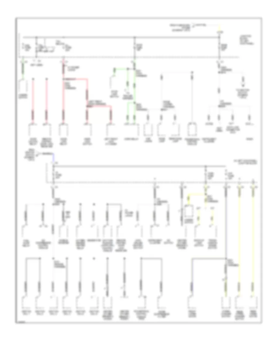
Power Distribution Wiring Diagram (2 of 2) for Chevrolet Tracker 2004
 https://portal-diagnostov.com/license.html
Automotive Electricians Portal FZCO
Automotive Electricians Portal FZCO
https://portal-diagnostov.com/license.html
https://portal-diagnostov.com/license.html
Automotive Electricians Portal FZCO
Automotive Electricians Portal FZCOList of elements for Power Distribution Wiring Diagram (2 of 2) for Chevrolet Tracker 2004:
- (dome jumper harness)
- (i/p harness) s250
- (i/p harness) s255
- (in left kick panel) junction block
- (main harness) s205
- (main harness) s218
- (not used)
- A/c compressor control module
- A/c switch
- A/t
- Abs w/ 4wd
- Accele- rometer
- Back-up lamp switch
- D/l fuse 20a
- Data link connector (dlc)
- Daytime running lamps (drl) control module
- Dome fuse 10a
- Dome lamp
- Door lock relay
- Door lock switch
- Door unlock relay
- From fuse block a ig fuse (diagram 1 of 2)
- From ignition switch d (diagram 1 of 2)
- Front wiper motor
- Fuel pump relay
- Generator
- Haz fuse 15a
- Hazard switch
- Heated oxygen sensor 1 (ho2s1)
- Heated oxygen sensor 2 (ho2s2)
- Horn relay
- Ig fuse 20a
- Ignition coil 1
- Ignition coil 2
- Ignition coil 3
- Ignition coil 4
- Ignition coil 5
- Ignition coil 6
- Instrument cluster
- Junction block (in left kick panel)
- Left front lock cylinder
- M/t
- Main cruise control switch
- Map lamps
- Noise suppressor filter
- Oxygen sensor heater relay
- Powertrain control module
- Powertrain control module (pcm)
- Radio
- Rear dome lamp
- Rear wiper motor
- Rear wiper/ washer switch
- Remote control door lock receiver
- S101 (engine harness)
- S211 (main harness)
- S221 (main harness)
- S231 (main harness)
- S241 (main harness)
- S242 (main harness)
- S311
- Stop fuse 15a
- Stop lamp switch
- Tail fuse 15a
- Tail relay
- To ignition switch (diagram 1 of 2)
- To trailer harness
- Trans- mission range switch
- Turn fuse 10a
- W/ power locks
- Wip fuse 15a
- Wiper/ washer switch
POWER DOOR LOCKS
Power Door Locks Wiring Diagram for Chevrolet Tracker 2004
 https://portal-diagnostov.com/license.html
Automotive Electricians Portal FZCO
Automotive Electricians Portal FZCO
https://portal-diagnostov.com/license.html
https://portal-diagnostov.com/license.html
Automotive Electricians Portal FZCO
Automotive Electricians Portal FZCOList of elements for Power Door Locks Wiring Diagram for Chevrolet Tracker 2004:
- (behind right side of dash, near blower assembly) g201
- (left front door harness) s501
- (main harness)
- (main harness) s223
- Batt
- D/l fuse 20a
- Data link connector (dlc) (below left side of dash, right of steering column)
- Dlc
- Door lock relay (to right of brake pedal)
- Door lock switch
- Door unlock relay (to right of brake pedal)
- Driver's door unlock ctrl
- Gnd
- Hot at all times
- Hot in run or start
- Ig fuse 20a
- Ign
- Interior lights system
- Junction block (in left kick panel)
- Left front door lock
- Left front lock cylinder
- Left rear door lock
- Lock
- Lock ctrl
- Pnk
- Rear door lock
- Rear lock cylinder
- Red
- Remote control door lock receiver (above accelerator pedal)
- Right front door lock
- Right front lock cylinder
- Right rear door lock
- S205
- S221
- S224 (main harness)
- S225 (main harness)
- S226 (main harness)
- S227 (main harness)
- S228
- S308 (floor harness)
- S309 (floor harness)
- S500 (left front door harness)
- Sp201 (main harness)
- Un- lock
- Unlock ctrl
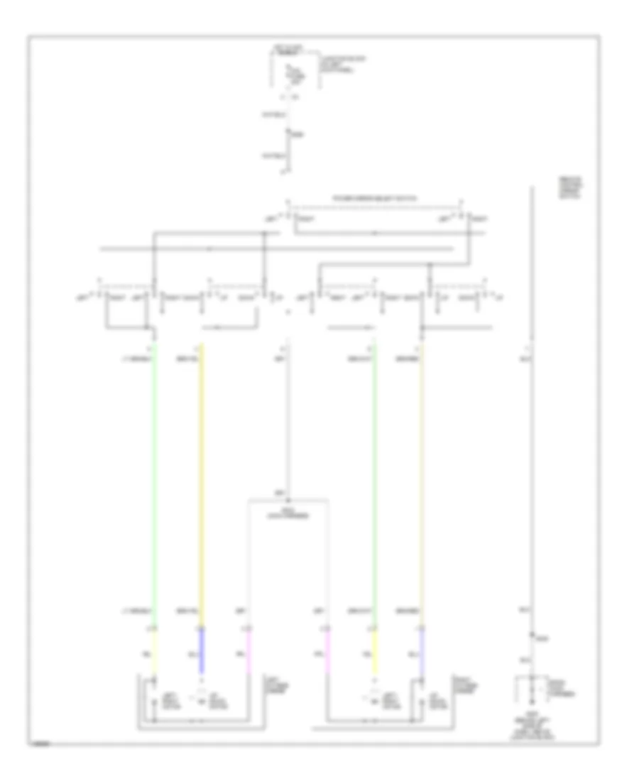
POWER MIRRORS
Power Mirrors Wiring Diagram for Chevrolet Tracker 2004
 https://portal-diagnostov.com/license.html
Automotive Electricians Portal FZCO
Automotive Electricians Portal FZCO
https://portal-diagnostov.com/license.html
https://portal-diagnostov.com/license.html
Automotive Electricians Portal FZCO
Automotive Electricians Portal FZCOList of elements for Power Mirrors Wiring Diagram for Chevrolet Tracker 2004:
- Cig fuse 20a
- Down
- G200 (behind left side of dash, above junction block)
- Hot in acc or run
- Junction block (in left kick panel)
- Left
- Left outside mirror
- Left/ right motor
- Power mirror select switch
- Remote control mirror switch
- Right
- Right outside mirror
- S243 (main harness)
- S248
- S256
- Sp200 (main harness)
- Up/ down motor
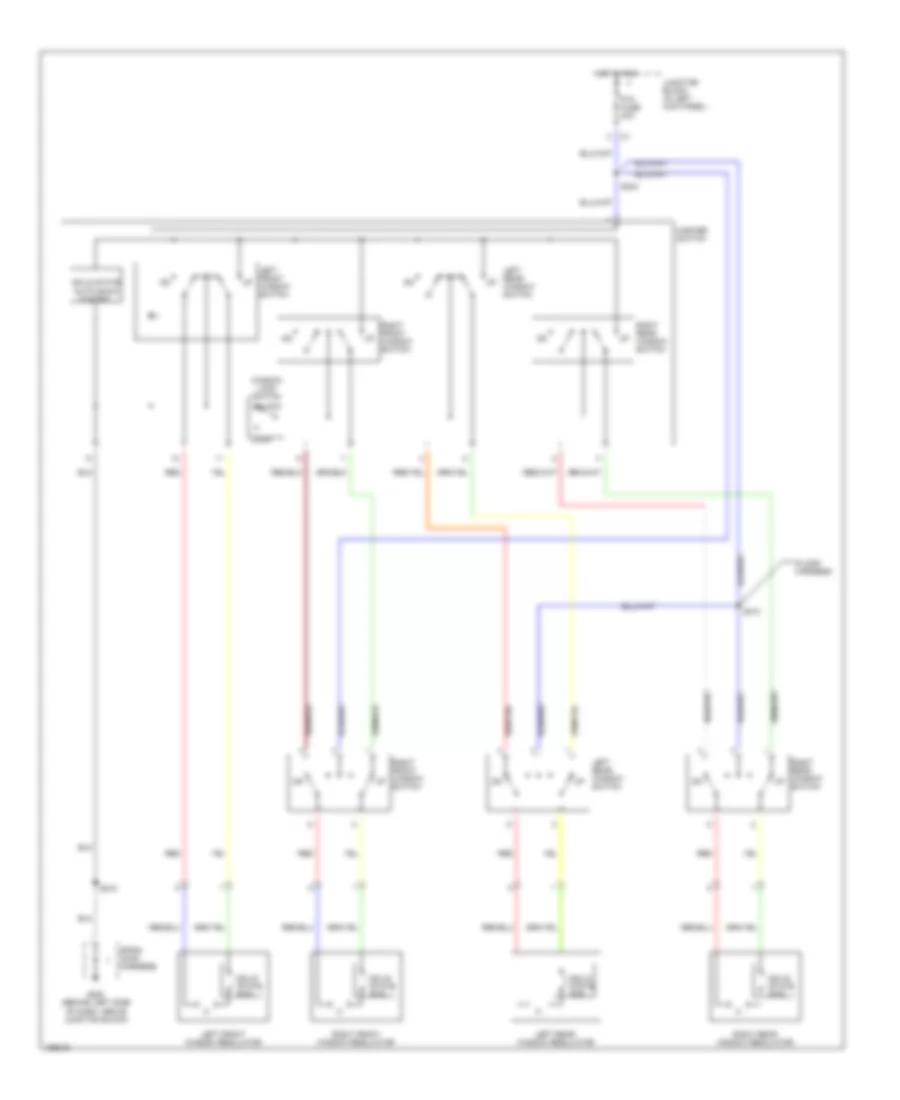
POWER WINDOWS
Power Windows Wiring Diagram for Chevrolet Tracker 2004
 https://portal-diagnostov.com/license.html
Automotive Electricians Portal FZCO
Automotive Electricians Portal FZCO
https://portal-diagnostov.com/license.html
https://portal-diagnostov.com/license.html
Automotive Electricians Portal FZCO
Automotive Electricians Portal FZCOList of elements for Power Windows Wiring Diagram for Chevrolet Tracker 2004:
- (floor harness)
- G200 (behind left side of dash, above junction block)
- Hot in run
- Junction block (in left kick panel)
- Left front window regulator
- Left front window switch
- Left rear window regulator
- Left rear window switch
- Lock
- Master switch
- P/w fuse 30a
- Red
- Right front window regulator
- Right front window switch
- Right rear window regulator
- Right rear window switch
- S210
- S244
- S310
- Solid state auto down control
- Solid state ecb
- Sp200 (main harness)
- Unlock
- Window lock switch
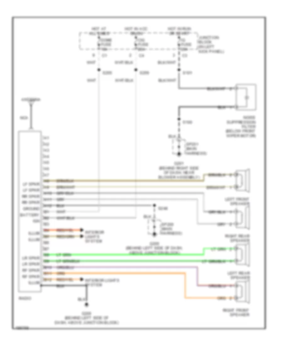
RADIO
Radio Wiring Diagram for Chevrolet Tracker 2004
 https://portal-diagnostov.com/license.html
Automotive Electricians Portal FZCO
Automotive Electricians Portal FZCO
https://portal-diagnostov.com/license.html
https://portal-diagnostov.com/license.html
Automotive Electricians Portal FZCO
Automotive Electricians Portal FZCOList of elements for Radio Wiring Diagram for Chevrolet Tracker 2004:
- A10
- A11
- A12
- Antenna
- B10
- B11
- B12
- Battery
- Cig fuse 20a
- Dome fuse 10a
- G200 (behind left side of dash, above junction block)
- G201 (behind right side of dash, near blower assembly)
- Ground
- Hot at all times
- Hot in acc or on
- Hot in run or start
- Ig fuse 20a
- Ign
- Illum
- Interior lights system
- Junction block (in left kick panel)
- Left front speaker
- Left rear speaker
- Lf spkr
- Lr spkr
- Nca
- Noise suppression filter (below front wiper motor)
- Radio
- Rf spkr
- Right front speaker
- Right rear speaker
- Rr spkr
- S100
- S101
- S248
- S255
- S256
- Sp200 (main harness)
- Sp201 (main harness)
SHIFT INTERLOCK
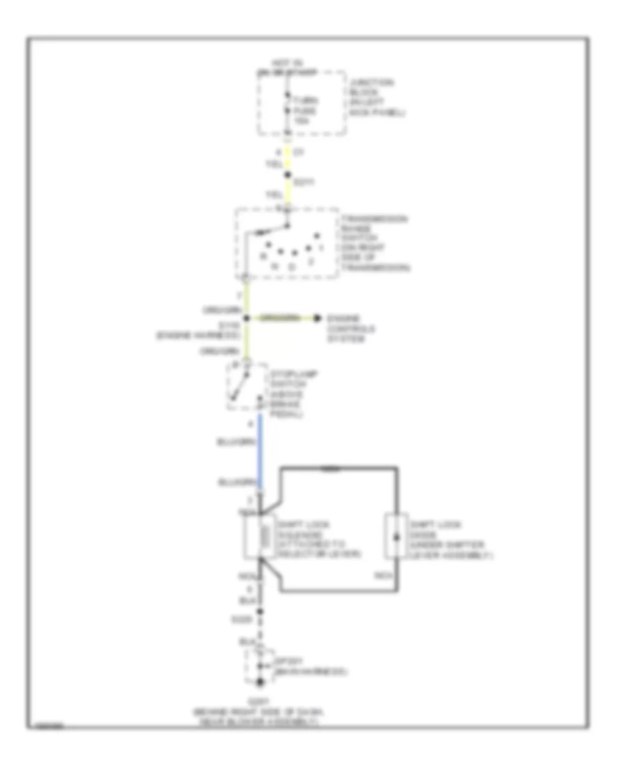
Shift Interlock Wiring Diagram, with Cruise Control for Chevrolet Tracker 2004
 https://portal-diagnostov.com/license.html
Automotive Electricians Portal FZCO
Automotive Electricians Portal FZCO
https://portal-diagnostov.com/license.html
https://portal-diagnostov.com/license.html
Automotive Electricians Portal FZCO
Automotive Electricians Portal FZCOList of elements for Shift Interlock Wiring Diagram, with Cruise Control for Chevrolet Tracker 2004:
- Engine controls system
- G105 (right front of core support, near horn)
- G201 (behind right side of dash, near blower assembly)
- Hot at all times
- Hot in on or start
- Junction block (in left kick panel)
- Nca
- S110 (engine harness)
- S201
- S211
- S213 (main harness)
- S220
- S241
- Shift lock diode (under shifter lever assembly)
- Shift lock relay (on right side of engine compt, in front of battery)
- Shift lock solenoid (attached to selector lever)
- Sp201 (main harness)
- Stop fuse 15a
- Stoplamp switch (above brake pedal)
- Transmission range switch (on right side of transmission)
- Turn fuse 10a
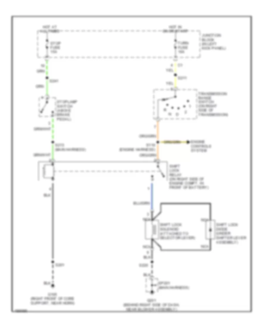
Shift Interlock Wiring Diagram, without Cruise Control for Chevrolet Tracker 2004
 https://portal-diagnostov.com/license.html
Automotive Electricians Portal FZCO
Automotive Electricians Portal FZCO
https://portal-diagnostov.com/license.html
https://portal-diagnostov.com/license.html
Automotive Electricians Portal FZCO
Automotive Electricians Portal FZCOList of elements for Shift Interlock Wiring Diagram, without Cruise Control for Chevrolet Tracker 2004:
- Engine controls system
- G201 (behind right side of dash, near blower assembly)
- Hot in on or start
- Junction block (in left kick panel)
- Nca
- S110 (engine harness)
- S211
- S220
- Shift lock diode (under shifter lever assembly)
- Shift lock solenoid (attached to selector lever)
- Sp201 (main harness)
- Stoplamp switch (above brake pedal)
- Transmission range switch (on right side of transmission)
- Turn fuse 10a
STARTING/CHARGING
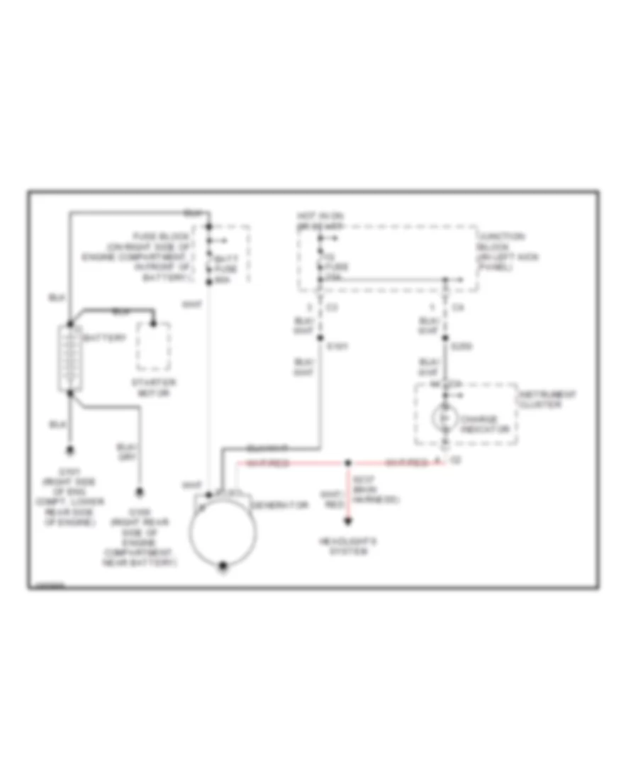
Charging Wiring Diagram for Chevrolet Tracker 2004
 https://portal-diagnostov.com/license.html
Automotive Electricians Portal FZCO
Automotive Electricians Portal FZCO
https://portal-diagnostov.com/license.html
https://portal-diagnostov.com/license.html
Automotive Electricians Portal FZCO
Automotive Electricians Portal FZCOList of elements for Charging Wiring Diagram for Chevrolet Tracker 2004:
- Batt fuse 80a
- Battery
- Charge indicator
- Fuse block (on right side of engine compartment, in front of battery)
- G100 (right rear side of engine compartment, near battery)
- G101 (right side of eng compt, lower rear side of engine)
- Generator
- Headlights system
- Hot in on or start
- Ig fuse 20a
- Instrument cluster
- Junction block (in left kick panel)
- S101
- S250
- Starter motor
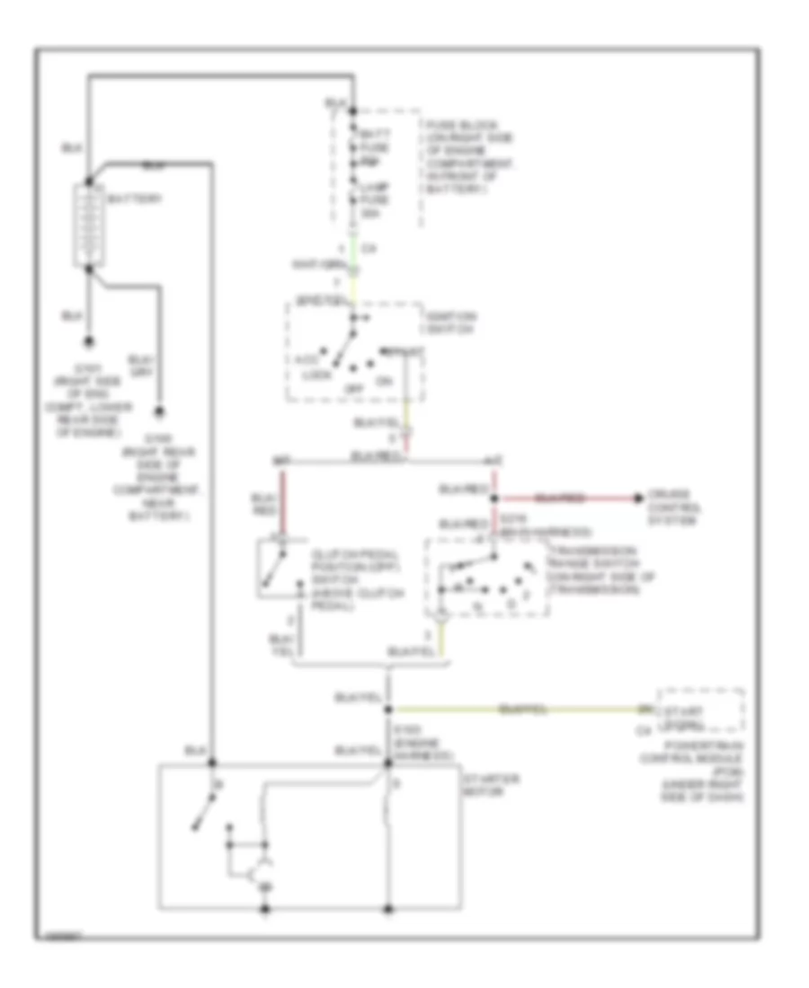
Starting Wiring Diagram for Chevrolet Tracker 2004
 https://portal-diagnostov.com/license.html
Automotive Electricians Portal FZCO
Automotive Electricians Portal FZCO
https://portal-diagnostov.com/license.html
https://portal-diagnostov.com/license.html
Automotive Electricians Portal FZCO
Automotive Electricians Portal FZCOList of elements for Starting Wiring Diagram for Chevrolet Tracker 2004:
- A/t
- Acc
- Batt fuse 80a
- Battery
- Clutch pedal position (cpp) switch (above clutch pedal)
- Cruise control system
- Fuse block (on right side of engine compartment, in front of battery)
- G100 (right rear side of engine compartment, near battery)
- G101 (right side of eng compt, lower rear side of engine)
- Ignition switch
- Lamp fuse 30a
- Lock
- M/t
- Off
- Powertrain control module (pcm) (under right side of dash)
- Start
- Start signal
- Starter motor
- Transmission range switch (on right side of transmission)
SUPPLEMENTAL RESTRAINTS
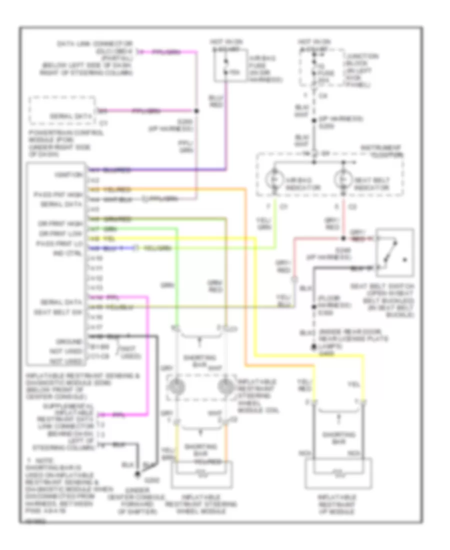
Supplemental Restraints Wiring Diagram for Chevrolet Tracker 2004
 https://portal-diagnostov.com/license.html
Automotive Electricians Portal FZCO
Automotive Electricians Portal FZCO
https://portal-diagnostov.com/license.html
https://portal-diagnostov.com/license.html
Automotive Electricians Portal FZCO
Automotive Electricians Portal FZCOList of elements for Supplemental Restraints Wiring Diagram for Chevrolet Tracker 2004:
- (floor harness) s300
- (i/p harness) s250
- (not used)
- (under center console, forward of shifter)
- 15a
- A10
- A11
- A12
- A13
- A14
- A15
- A16
- A17
- A18
- Air bag fuse (in sir harness)
- Air bag indicator
- B1-b8
- C1-c8
- Data link connector (dlc) obd-ii (partial) (below left side of dash, right of steering column)
- Dr frnt high
- Dr frnt low
- G202
- Ground
- Hot in on & start
- Ig fuse 20a
- Ignition
- Ind ctrl
- Inflatable restraint i/p module
- Inflatable restraint sensing & diagnostic module (sdm) (below front of center console)
- Inflatable restraint steering wheel module
- Inflatable restraint steering wheel module coil
- Instrument cluster
- Junction block (in left kick panel)
- Left of steering column)
- Nca
- Near license plate lamps) g400
- Not used
- Note:
- Pass fnt high
- Pass frnt lo
- Powertrain control module (pcm) (under right side of dash)
- Restraint data link connector (behind dash,
- S249 (i/p harness)
- S260 (i/p harness)
- Seat belt indicator
- Seat belt sw
- Seat belt switch (open w/seat belt buckled) (in seat belt buckle)
- Serial data
- Shorting bar
- Shorting bar is used on inflatable restraint sensing & diagnostic module when disconnected from harness, between pins: a9-a18
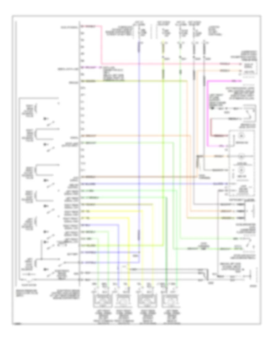
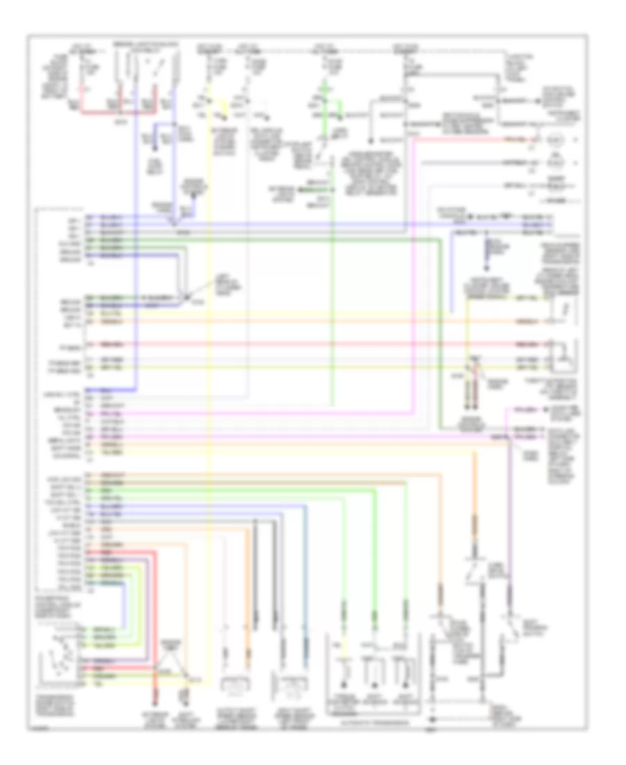
TRANSMISSION
A/T Wiring Diagram for Chevrolet Tracker 2004
 https://portal-diagnostov.com/license.html
Automotive Electricians Portal FZCO
Automotive Electricians Portal FZCO
https://portal-diagnostov.com/license.html
https://portal-diagnostov.com/license.html
Automotive Electricians Portal FZCO
Automotive Electricians Portal FZCOList of elements for A/T Wiring Diagram for Chevrolet Tracker 2004:
- (beside junction block) main relay
- (dash harn)
- (engine harn)
- (left rear of cylinder head)
- (on intake manifold) g103
- (rear of left cylinder head) engine coolant temperature (ect) sensor
- 4wd low sig
- A/c switch, main cruise control switch
- Accelerometer, drl control module, remote control door lock receiver, fuel pump relay, a/c comp control module, o2 heater relay, generator
- Automatic transmission
- Brake sw
- Computer data lines system
- Data link connector (dlc) obd ii (partial) (below left side of dash, right of steering column)
- Dlc gnd
- Dome fuse 10a
- Drl module, data link connector, instrument cluster, radio
- Ect in
- Engine controls system
- Exterior lights system
- Exterior lights system (hazard switch)
- Exterior lights system,
- F1 fuse 15a
- Four wheel drive low switch (top of transfer case)
- Fuel pump relay
- Fuse block (on right side of engine compt, in front of battery)
- G102
- G201
- Ground
- Harn)
- Hi a/t iss
- Hi a/t oss
- Horn relay
- Hot at all times
- Hot in on & start
- Ig fuse 20a
- Ign +
- Ignition coils, noise suppressor filter, heated oxygen sensors
- Input shaft speed sensor (left front of trans)
- Instrument cluster
- Instrument cluster, cruise control system (speed signal)
- Junction block (in left kick panel)
- Low a/t iss
- Low a/t oss
- Main rly ctrl
- Mil
- Mil ctrl
- Nca
- O/d ind
- O/d signal
- Od/off
- Output shaft speed sensor (lower right rear of trans)
- Over- drive switch
- P/n ind
- Power
- Powertrain control module (under right side of dash)
- Red
- S100
- S101
- S102
- S106
- S107
- S108
- S109
- S110
- S117
- S205
- S211
- S213
- S218
- S219
- S220
- S241
- S250
- S260
- Serial data
- Shield
- Shift interlock system
- Shift mode
- Shift program switch
- Shift sol 1
- Shift sol 2
- Shift solenoid
- Sp201 (behind right side of dash)
- Stop fuse 15a
- Stoplamp switch (above brake pedal)
- Tcc sol ctrl
- Throttle position (tp) sensor (on throttle assembly)
- Torque converter clutch solenoid
- Tp sens
- Tp sens gnd
- Tp sens ref
- Tr 2 pos
- Tr d pos
- Tr l pos
- Tr n pos
- Tr p pos
- Tr r pos
- Transmission range switch (right side of transmission)
- Turn fuse 10a
- Vehicle speed sensor (vss) (right side of transmission)
- Vss hi
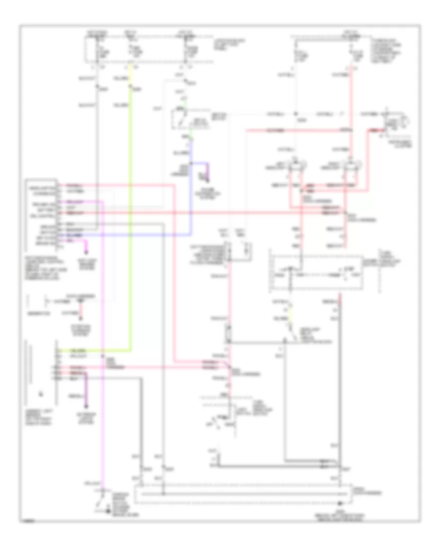
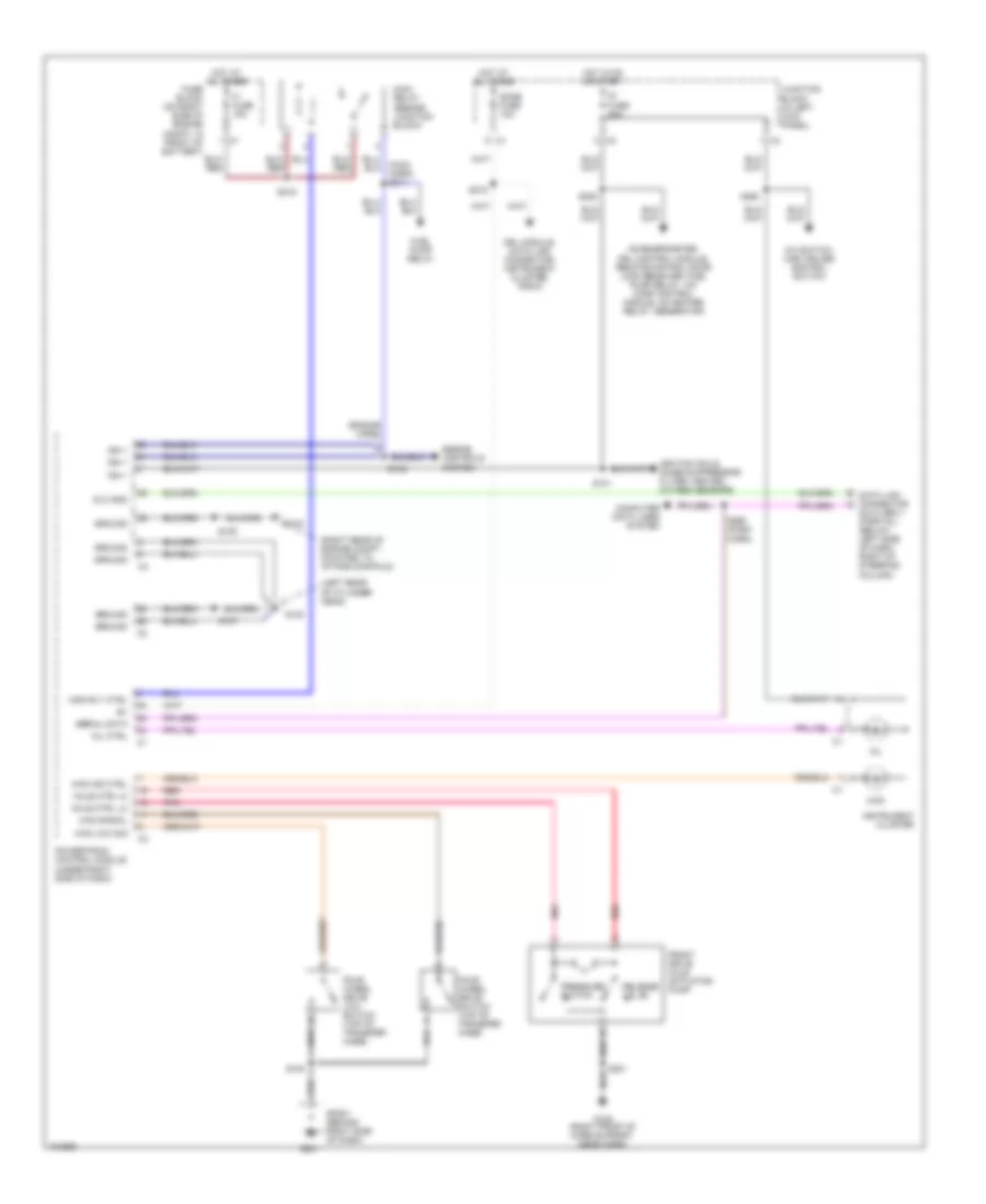
Transfer Case Wiring Diagram for Chevrolet Tracker 2004
 https://portal-diagnostov.com/license.html
Automotive Electricians Portal FZCO
Automotive Electricians Portal FZCO
https://portal-diagnostov.com/license.html
https://portal-diagnostov.com/license.html
Automotive Electricians Portal FZCO
Automotive Electricians Portal FZCOList of elements for Transfer Case Wiring Diagram for Chevrolet Tracker 2004:
- (engine harn)
- (left rear of cylinder head)
- (right rear of engine compt, mounted to intake manifold)
- 4wd
- 4wd ind ctrl
- 4wd low sig
- 4wd signal
- A/c switch, main cruise control switch
- Accelerometer, drl control module, remote control door lock receiver, fuel pump relay, a/c comp control module, o2 heater relay, generator
- Axle ctrl hi
- Axle ctrl lo
- Computer data lines system
- Data link connector (dlc) obd ii (partial) (below left side of dash, right of steering column)
- Dlc gnd
- Dome fuse 10a
- Drl module, data link connector, instrument cluster, radio
- Engine controls system
- F1 fuse 15a
- Four wheel drive low switch (top of transfer case)
- Four wheel drive switch (top of transfer case)
- Front drive axle actuator pump
- Fuel pump relay
- Fuse block (on right side of engine compt, in front of battery)
- G102
- G103
- G105 (right front of core support, near horn)
- G201
- Ground
- Hot at all times
- Hot in on or start
- Ig fuse 20a
- Ign +
- Ignition coils, noise suppressor filter, heated oxygen sensors
- Instrument cluster
- Junction block (in left kick panel)
- Main relay (beside junction block)
- Main rly ctrl
- Mil
- Mil ctrl
- Pnk
- Powertrain control module (under right side of dash)
- Pressure switch
- Red
- Release valve
- S100
- S101
- S102
- S105
- S107
- S201
- S205
- S218
- S219
- S250
- S260 (dash harn)
- Serial data
- Sp201 (behind right side of dash)
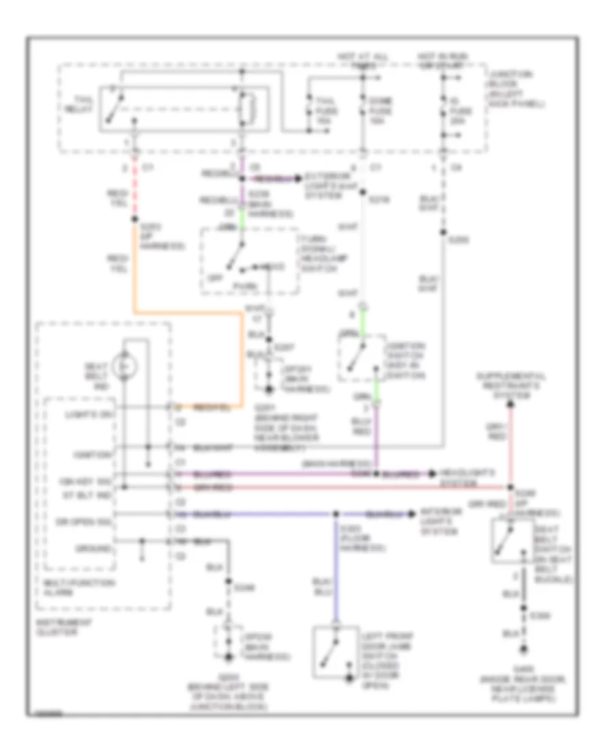
WARNING SYSTEMS
Warning Systems Wiring Diagram for Chevrolet Tracker 2004
 https://portal-diagnostov.com/license.html
Automotive Electricians Portal FZCO
Automotive Electricians Portal FZCO
https://portal-diagnostov.com/license.html
https://portal-diagnostov.com/license.html
Automotive Electricians Portal FZCO
Automotive Electricians Portal FZCOList of elements for Warning Systems Wiring Diagram for Chevrolet Tracker 2004:
- Dome fuse 10a
- Dr open sig
- Exterior lights system
- G200 (behind left side of dash, above junction block)
- G201 (behind right side of dash, near blower assembly)
- G400 (inside rear door, near license plate lamps)
- Ground
- Harness)
- Head
- Headlights system
- Hot at all times
- Hot in run or start
- Ig fuse 20a
- Ign key sig
- Ignition
- Ignition switch (key-in switch)
- Instrument cluster
- Interior lights system
- Junction block (in left kick panel)
- Left front door jamb switch (closed w/ door open)
- Lights on
- Multi-function alarm
- Off
- Park
- S207
- S218
- S239 (main harness)
- S248
- S250
- S253 (i/p harness)
- S300
- S303 (floor harness)
- Seat belt ind
- Seat belt switch (in seat belt buckle)
- Sp200 (main harness)
- Sp201 (main harness)
- St blt ind
- Tail fuse 15a
- Tail relay
- Turn signal/ headlamp switch
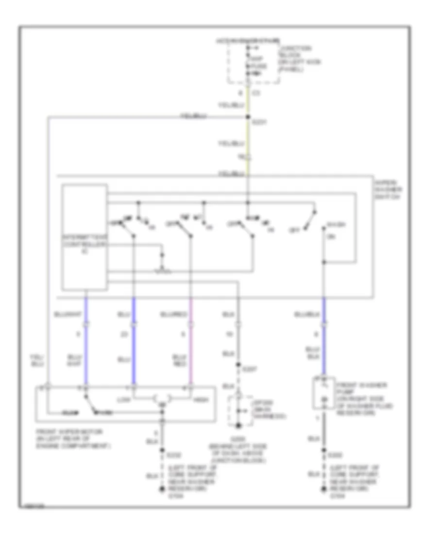
WIPER/WASHER
Front Wiper/Washer Wiring Diagram for Chevrolet Tracker 2004
 https://portal-diagnostov.com/license.html
Automotive Electricians Portal FZCO
Automotive Electricians Portal FZCO
https://portal-diagnostov.com/license.html
https://portal-diagnostov.com/license.html
Automotive Electricians Portal FZCO
Automotive Electricians Portal FZCOList of elements for Front Wiper/Washer Wiring Diagram for Chevrolet Tracker 2004:
- (left front of core support, near washer reservoir) g104
- Front washer pump (on right side of washer fluid reservoir)
- Front wiper motor (in left rear of engine compartment)
- G200 (behind left side of dash, above junction block)
- High
- Hot in on or start
- Int
- Int off
- Intermittent controller ic
- Junction block (in left kick panel)
- Low
- Off
- Park
- Run
- S202
- S207
- S231
- S232
- Sp200 (main harness)
- Wash
- Wip fuse 15a
- Wiper/ washer switch
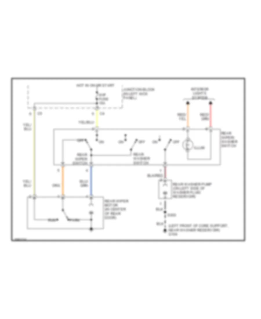
Rear Wiper/Washer Wiring Diagram for Chevrolet Tracker 2004
 https://portal-diagnostov.com/license.html
Automotive Electricians Portal FZCO
Automotive Electricians Portal FZCO
https://portal-diagnostov.com/license.html
https://portal-diagnostov.com/license.html
Automotive Electricians Portal FZCO
Automotive Electricians Portal FZCOList of elements for Rear Wiper/Washer Wiring Diagram for Chevrolet Tracker 2004:
- (left front of core support, near washer reservoir) g104
- Hot in on or start
- Illum
- Interior lights system
- Junction block (in left kick panel)
- Off
- Park
- Rear washer pump (on left side of washer fluid reservoir)
- Rear washer switch
- Rear wiper motor (in center of rear door)
- Rear wiper switch
- Rear wiper/ washer switch
- Run
- S202
- Wip fuse 15a

 Čeština
 Dansk
Dansk Deutsch
 Ελληνικά
 English
 English
 Español
 Suomi
Suomi Français
 Français
 Hrvatski
 Magyar
 Italiano
 日本語
日本語 한국어
한국어 Nederlands
 Polski
 Português
 Português
 Română
 Русский
 Slovenčina
 Slovenščina
 Svenska
 Türkçe
 中文 (中国)
