AIR CONDITIONING
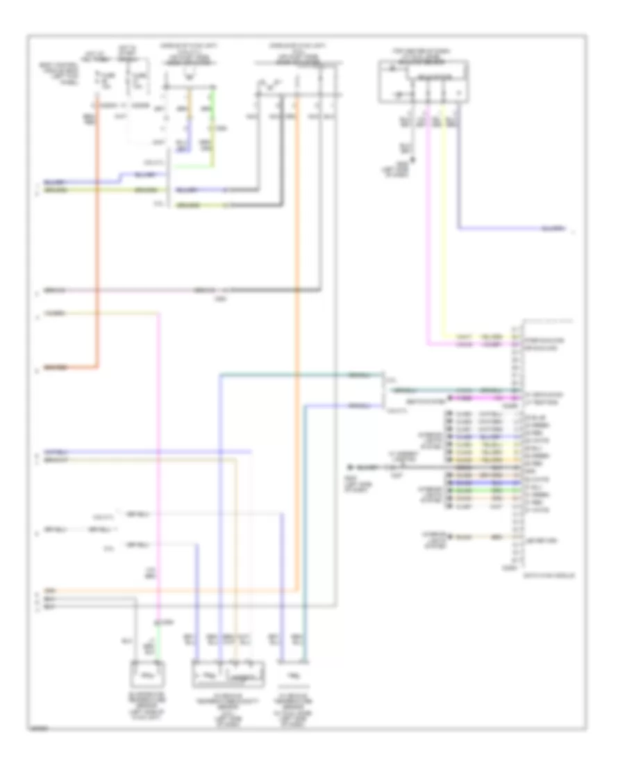
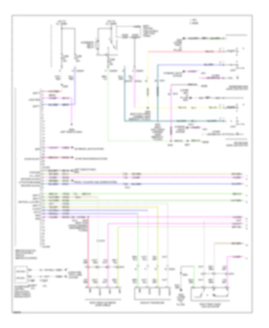
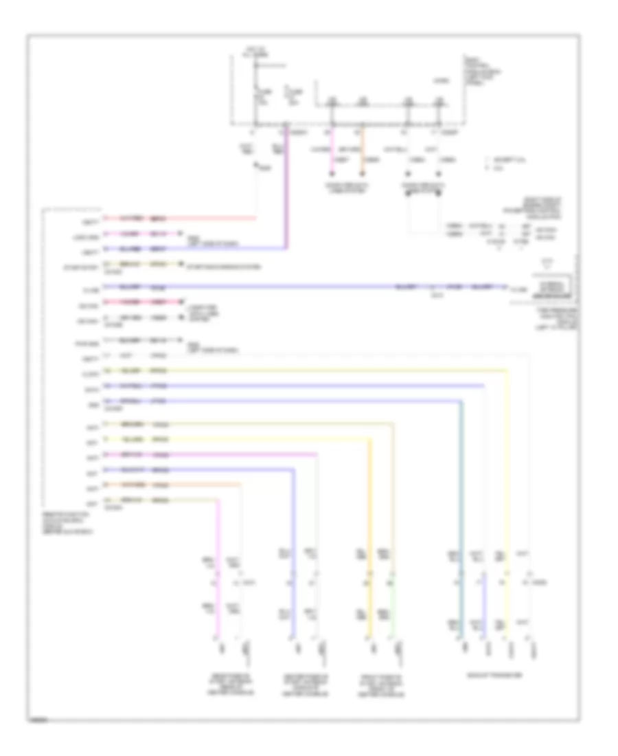
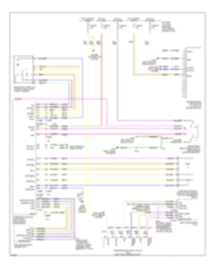
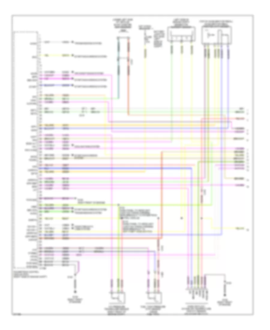
Automatic A/C Wiring Diagram (1 of 3) for Ford Edge Limited 2013
 https://portal-diagnostov.com/license.html
Automotive Electricians Portal FZCO
Automotive Electricians Portal FZCO
https://portal-diagnostov.com/license.html
https://portal-diagnostov.com/license.html
Automotive Electricians Portal FZCO
Automotive Electricians Portal FZCO
List of elements for Automatic A/C Wiring Diagram (1 of 3) for Ford Edge Limited 2013:
- (a/c wiring harness, near breakout to air inlet mode door actuator)
- (main wiring harness, near breakout to accessory protocol interface module)
- (main wiring harness, near breakout to g205)
- (near blower motor) blower motor speed control
- (right side of dash) blower motor
- Battery junction box (bjb) (left side of engine compt)
- Blower motor relay
- Blwr rly
- C215
- C228a
- C228b
- C260
- C264
- Ch102
- Ch122
- Ch123
- Ch207
- Ch208
- Ch212
- Ch213
- Ch228
- Ch229
- Ch238
- Ch239
- Chs02
- Chs07
- Computer data lines system
- Datc hvac module
- Defogger system
- Defrost/panel/ floor mode door actuator (left side of hvac unit)
- Defrst req
- Edge w/ heated seats
- Evap
- Feedback
- Fuse 30a
- Fuse 40a
- Fuse 5a
- G205 (left side of dash)
- Gd115
- Gnd
- Hot at all times
- Hot in start or run
- Humidity signal
- Left temperature blend door actuator (left side of hvac unit)
- Lf heater
- Lh111
- Module) s219
- Ms can +
- Ms can -
- Mtr +
- Mtr -
- Red
- Rf heater
- Rftemp sns
- Rh111
- Right temperature blend door actuator (middle front of hvac unit)
- S207
- S216
- S217 (a/c wiring harness, near breakout to air inlet mode door actuator)
- S218
- S245
- Sbb28
- Sbp46
- Seats system
- Sig return
- Var blw feed
- Var blwr ctrl
- Vbatt
- Vdb06
- Vdb07
- Vh101
- Vh406
- Vh413
- Vh436
- Vh438
- Vh440
- Vh441
- Vhs27
- Vref
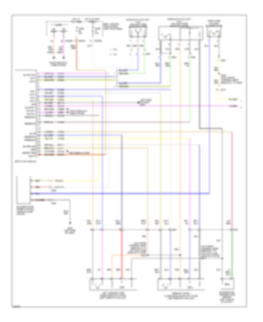
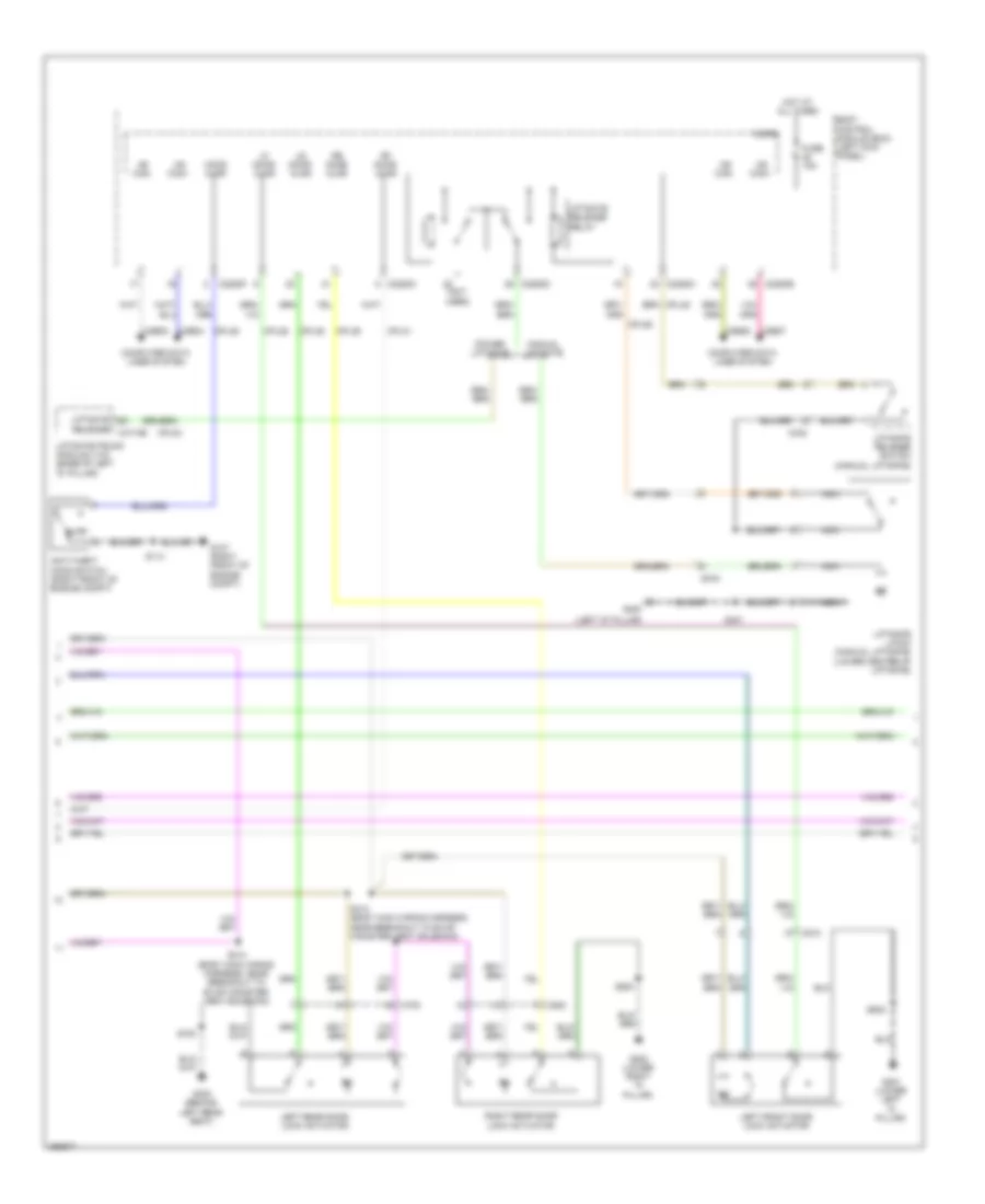
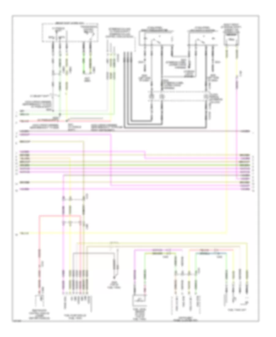
Automatic A/C Wiring Diagram (2 of 3) for Ford Edge Limited 2013
 https://portal-diagnostov.com/license.html
Automotive Electricians Portal FZCO
Automotive Electricians Portal FZCO
https://portal-diagnostov.com/license.html
https://portal-diagnostov.com/license.html
Automotive Electricians Portal FZCO
Automotive Electricians Portal FZCOList of elements for Automatic A/C Wiring Diagram (2 of 3) for Ford Edge Limited 2013:
- (middle of hvac unit) (2.0l) air inlet mode door actuator
- (middle of hvac unit) (3.5l/3.7l) air inlet mode door actuator
- (top center of dash) (w/ dual zone) sunload sensor
- 2.0l
- 3.5l/3.7l
- Body control module (bcm) (left kick panel)
- C2280a
- C2280b
- C228b
- C228c
- C237
- C264
- Cln44
- Cln45
- Cln46
- Cln48
- Cln49
- Cln50
- Cln51
- Cln52
- Cln53
- Cln57
- Cln58
- Cln59
- Datc hvac module
- Dr sunload
- Evaporator temperature sensor (left side of hvac unit)
- Fuse 10a
- G205 (left side of dash)
- Gd908
- Gnd
- Hot at all times
- Hot in start or run
- Humidity
- In vehicle sig
- In vehicle temperature sensor (w/ dual zone) (left side of dash)
- In-vehicle temperature/humidity sensor (2.0l) (left side of dash)
- Interior lights system
- Led return
- Lf temp sns
- Nca
- Pass sunload
- Rln44
- Seats system
- Solid state
- Vh414
- Vh416
- Vh417
- Vhs26
- W/ ambient lighting
- Z1 green
- Z1 red
- Z1 white
- Z2 green
- Z2 red
- Z2 white
- Z3 green
- Z3 red
- Z3 white
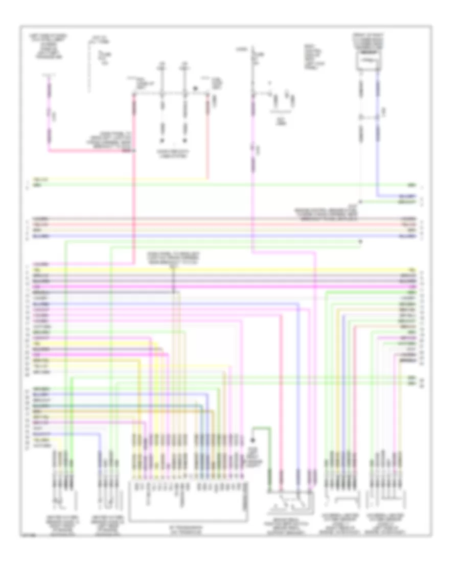
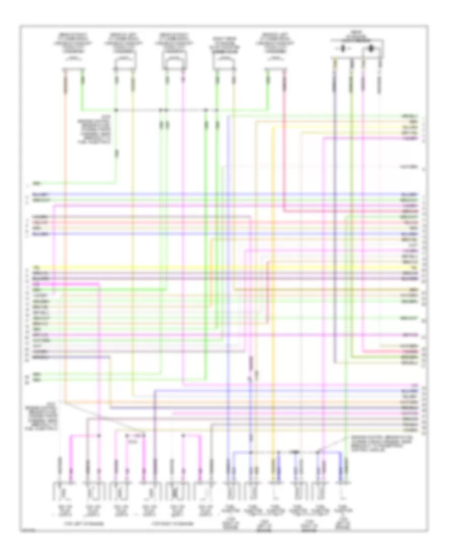
Automatic A/C Wiring Diagram (3 of 3) for Ford Edge Limited 2013
 https://portal-diagnostov.com/license.html
Automotive Electricians Portal FZCO
Automotive Electricians Portal FZCO
https://portal-diagnostov.com/license.html
https://portal-diagnostov.com/license.html
Automotive Electricians Portal FZCO
Automotive Electricians Portal FZCOList of elements for Automatic A/C Wiring Diagram (3 of 3) for Ford Edge Limited 2013:
- (3.5l/3.7l) a/c compressor clutch diode
- (dash panel to headlight junction wiring harness, near breakout to powertrain control module)
- (engine control sensor & fuel charge wiring harness, near breakout to coil on plug 3)
- (engine control sensor & fuel charge wiring harness, near breakout to coil on plug 1) (2.0l) s176
- (or re454)
- (right front of engine compt) g107
- 2.0l
- 3.5l/3.7l
- A/c clutch relay
- A/c compressor clutch field coil (a/c compressor)
- A/c pressure transducer sensor (right front of engine compt)
- Aat
- Accr
- Acpt
- Ambient air temperature (aat) sensor (right front of engine compt)
- Auto lamp sens in
- Battery junction box (bjb) (left side of engine compt)
- Body control module (bcm) (left kick panel)
- C110
- C1381b
- C1381e
- C140
- C175b
- C175e
- C192
- C2280b
- Ch302
- Cht
- Computer data lines system
- Cooling fan module (left front of engine compt)
- Cooling fan motors
- Cylinder head temperature sensor (front of right cylinder bank)
- Ect
- Electronics
- Engine coolant temperature sensor (2.0l)
- Evdc
- Externally controlled variable displacement compressosr (evdc) (2.0l) (right front of engine compt)
- Fan cntrl
- Fcv
- Fuse 10a
- Fuse 40a
- Fuse 60a 40a
- G103 (left side of engine compt)
- G105 (left front of engine compt)
- Gd123
- Gnd
- Hot at all times
- Hot w/ pcm power relay energized
- Hs can +
- Hs can -
- Le424
- Micro
- Ms can+
- Ms can-
- Powertrain control module (pcm) (right side of engine compt)
- Pwr
- Re405
- Re407
- Red
- S112
- S119 (dash panel to headlight junction wiring harness, near breakout to anti-theft hood switch)
- S122
- S127 (3.5l)
- Sbb39
- Sigrtn
- Vdb04
- Vdb05
- Vdb06
- Vdb07
- Ve462
- Ve712
- Ve716
- Vec03
- Vh407 (or ve740)
- Vh433
- Vlf14
- Vref
- W/ trailer tow
- W/o trailer tow
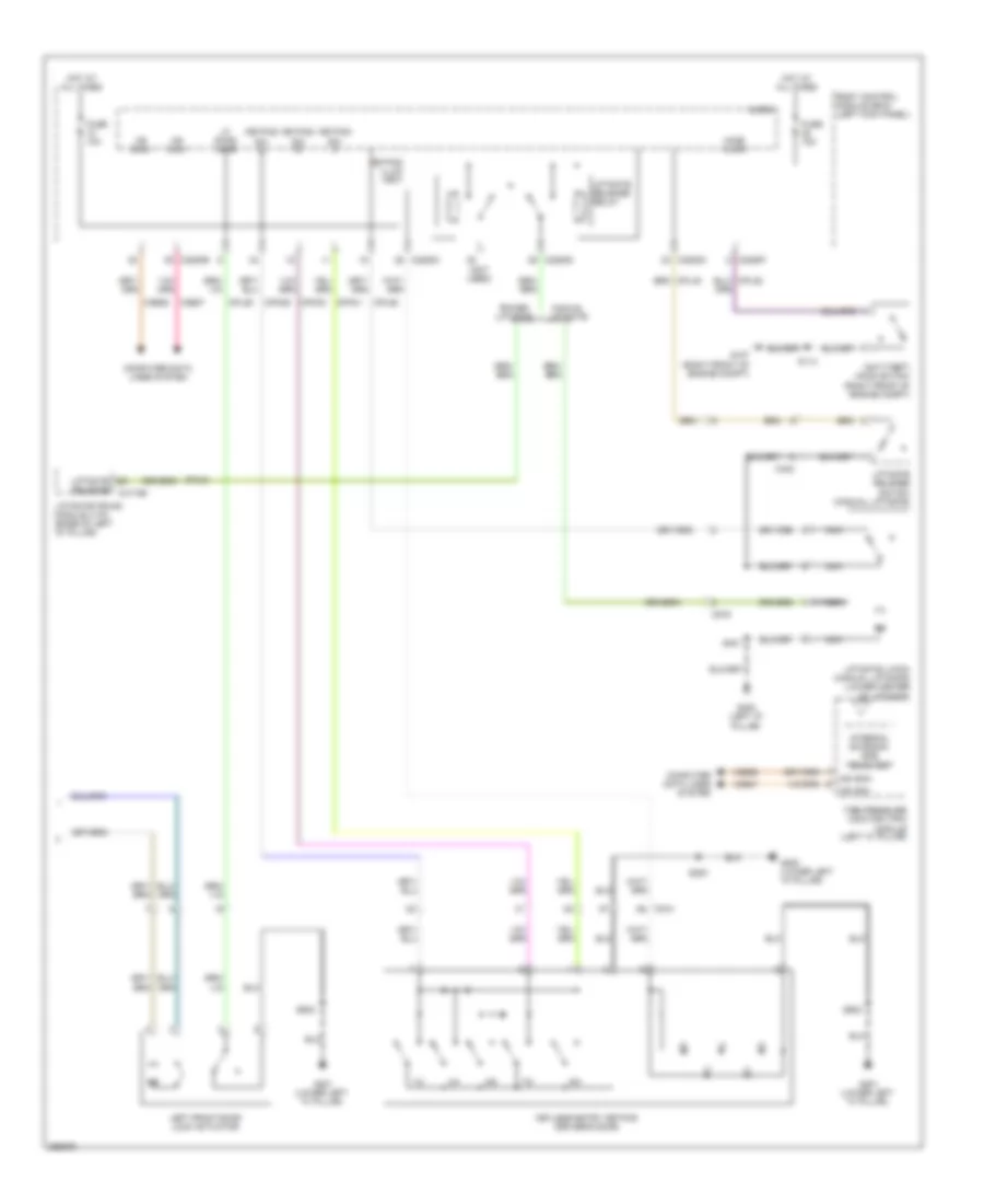
Manual A/C Wiring Diagram (1 of 2) for Ford Edge Limited 2013
 https://portal-diagnostov.com/license.html
Automotive Electricians Portal FZCO
Automotive Electricians Portal FZCO
https://portal-diagnostov.com/license.html
https://portal-diagnostov.com/license.html
Automotive Electricians Portal FZCO
Automotive Electricians Portal FZCOList of elements for Manual A/C Wiring Diagram (1 of 2) for Ford Edge Limited 2013:
- (a/c wiring harness, near breakout to air inlet mode door actuator) s217
- (a/c wiring harness, near breakout to air inlet mode door actuator) s218
- (left side of dash) g205
- (middle of hvac unit) (2.0l) air inlet mode door actuator
- (middle of hvac unit) (3.5l) air inlet mode door actuator
- (right side of dash) blower motor
- 2.0l
- 3.5l
- Blower motor speed control (near blower motor)
- Blwr ctrl
- Blwr rly
- Body control module (bcm) (left kick panel)
- C215
- C2280a
- C2280b
- C260
- C264
- Ch102
- Ch122
- Ch123
- Ch207
- Ch208
- Ch228
- Ch229
- Ch238
- Ch239
- Computer data lines system
- Defogger system
- Defrost/panel/ floor mode dooor actuator (left side of hvac unit)
- Defrst req
- Emtc hvac module
- Evap
- Evaporator temperature sensor (left side of hvac unit)
- Feedback
- Fuse 10a
- G205 (left side of dash)
- Gd115
- Gnd
- Hot at all times
- Hot in start or run
- Left temperature blend door actuator (left side of hvac unit)
- Lh111
- Micro
- Ms can +
- Ms can -
- Ms can+
- Ms can-
- Mtr +
- Mtr -
- Nca
- Red
- Rh111
- S245 (main wiring harness, near breakout to g205)
- Sbp46
- Sig return
- Vbatt
- Vdb06
- Vdb07
- Vh101
- Vh406
- Vh436
- Vh438
- Vh440
- Vref
Manual A/C Wiring Diagram (2 of 2) for Ford Edge Limited 2013
 https://portal-diagnostov.com/license.html
Automotive Electricians Portal FZCO
Automotive Electricians Portal FZCO
https://portal-diagnostov.com/license.html
https://portal-diagnostov.com/license.html
Automotive Electricians Portal FZCO
Automotive Electricians Portal FZCOList of elements for Manual A/C Wiring Diagram (2 of 2) for Ford Edge Limited 2013:
- (3.5l) a/c compressor clutch diode
- (dash panel to headlight junction wiring harness, near breakout to powertrain control module)
- (or re454)
- (right front of engine compt) g107
- 2.0l
- 3.5l
- A/c clutch relay
- A/c compressor clutch field coil (a/c compressor)
- A/c pressure transducer sensor (right front of engine compt)
- Aat
- Accr
- Acpt
- Ambient air temperature (aat) sensor (right front of engine compt)
- Battery junction box (bjb) (left side of engine compt)
- Blower motor relay
- C110
- C1381b
- C1381e
- C140
- C175b
- C175e
- C192
- C215
- Ch302
- Cht
- Computer data lines system
- Cooling fan module (left front of engine compt)
- Cooling fan motors
- Cylinder head temperature sensor (front of right cylinder bank)
- Ect
- Electronics
- Engine coolant temperature sensor (2.0l)
- Evdc
- Externally controlled variable displacement compressosr (evdc) (2.0l) (right front of engine compt)
- Fan cntrl
- Fcv
- Fuse 10a
- Fuse 40a
- Fuse 5a
- Fuse 60a 40a
- G103 (left side of engine compt)
- G105 (left front of engine compt)
- Gd123
- Gnd
- Hot at all times
- Hot in start or run
- Hot w/ pcm power relay energized
- Hs can +
- Hs can -
- Le424
- Powertrain control module (pcm) (right side of engine compt)
- Pwr
- Re405
- Re407
- Red
- S112
- S119 (dash panel to headlight junction wiring harness, near breakout to anti-theft hood switch)
- S122
- S127 (3.5l) (engine control sensor & fuel charge wiring harness, near breakout to coil on plug 3)
- Sbb39
- Sigrtn
- Vdb04
- Vdb05
- Ve462
- Ve712
- Ve716
- Vec03
- Vh407 (or ve740)
- Vh433
- Vref
- W/ trailer tow
- W/o trailer tow
ANTI-LOCK BRAKES
Anti-lock Brakes Wiring Diagram for Ford Edge Limited 2013
 https://portal-diagnostov.com/license.html
Automotive Electricians Portal FZCO
Automotive Electricians Portal FZCO
https://portal-diagnostov.com/license.html
https://portal-diagnostov.com/license.html
Automotive Electricians Portal FZCO
Automotive Electricians Portal FZCOList of elements for Anti-lock Brakes Wiring Diagram for Ford Edge Limited 2013:
- (brake pedal support bracket) brake pedal position (bpp) switch
- 2.0l
- 3.5l & 3.7l
- Anti-lock brake system (abs) module (left rear of engine compt)
- Battery junction box (bjb) (left side of engine compt)
- Body control module (bcm) (left kick panel)
- Bpp
- Bps
- C110
- C1381b
- C175b
- C212
- C215
- C2280a
- C2280b
- C2280f
- C2414a
- C2414b
- C310b
- Cbb92
- Ccb08
- Ces09
- Computer data lines system
- Fuse 24 15a
- Fuse 43 25a
- Fuse 5 40a
- Fuse 59 10a
- Fuse 92 10a
- G103 (left side of engine compt)
- G105 (left front of engine compt)
- G109 (right front of engine)
- G205 (left side of dash)
- Gd115
- Gd121
- Gnd
- Hot at all times
- Hot in on or start
- Hs can +
- Hs can -
- Hs can yaw +
- Hs can yaw -
- Ican+
- Ican-
- Instrument panel cluster (ipc)
- Isp-r
- Left front wheel speed sensor (left front wheel hub)
- Left rear wheel speed sensor (left rear wheel hub)
- Lf sens hi
- Lf sens lo
- Lr sens hi
- Lr sens lo
- Mtr b+
- Nca
- Powertrain control module (pcm) (right side of engine compt)
- Pwr gnd
- Rca17
- Rca18
- Rca19
- Rca20
- Remote function actuator (raf) module (behind glove box)
- Restraints control module (under center console)
- Rf sens hi
- Rf sens lo
- Right front wheel speed sensor (right front wheel hub)
- Right rear wheel speed sensor (right rear wheel hub)
- Rr sens hi
- Rr sens lo
- S120
- S228
- S267 (w/ intelligent access) (main wiring harness, near breakout to g205)
- Sbb05
- Sbb43
- Sbp24
- Steering column control module (sccm) (steering column)
- Vbatt
- Vca03
- Vca04
- Vca05
- Vca06
- Vca23
- Vca24
- Vdb04
- Vdb05
- Vlv b+
- W/ intelligent access
ANTI-THEFT
Forced Entry Wiring Diagram, with Intelligent Access (1 of 3) for Ford Edge Limited 2013
 https://portal-diagnostov.com/license.html
Automotive Electricians Portal FZCO
Automotive Electricians Portal FZCO
https://portal-diagnostov.com/license.html
https://portal-diagnostov.com/license.html
Automotive Electricians Portal FZCO
Automotive Electricians Portal FZCOList of elements for Forced Entry Wiring Diagram, with Intelligent Access (1 of 3) for Ford Edge Limited 2013:
- (left side of dash) g205
- (lower left "a" pillar) g201
- 2.0l
- Accessory delay relay
- All lock
- Ant+
- Ant-
- Backup tranceiver
- Body control module (bcm) (left kick panel)
- Bpp
- C1381b
- C175b
- C213
- C2153c
- C2153d
- C219
- C2280a
- C2280c
- C2280d
- C3053
- C510
- C610
- Ccb08
- Clock
- Computer data lines system
- Cpk19
- Cpk23
- Cpk28
- Cpk34
- Cpl11
- Cpl51
- Cpl52
- Cpl84
- Data
- Door lock
- Door unlock
- Dr door unlock
- Driver side door lock switch
- Edge
- Except 2.0l
- Exterior lights system
- Fuse 15a
- Fuse 20a
- G202 (lower right "a" pillar)
- G205 (left side of dash)
- Gd115
- Gnd
- Hot at all times
- Hs can+
- Hs can-
- Interior lights system
- Keypad illum (fet)
- Liftgate release
- Lock
- Logic gnd
- Lpk32
- Micro
- Mkx
- Passenger side door lock switch
- Powertrain control module (pcm) (right side of engine compt)
- Pwr gnd
- Remote function actuator (rfa) module (behind glove box)
- Right front door lock actuator
- Right front exterior door handle
- Rpk32
- Rpk39
- S229
- S252 (body main wiring harness, near breakout to c510)
- S253 (body main wiring harness, near breakout to c510)
- S370 (body main wiring harness, near breakout to g200)
- S382
- S502
- S507
- S604
- Sbp23
- Sbp27
- Start/stop1
- Starting/charging system
- Trunk, tailgate, fuel doors system
- Unlock
- Vbatt
- Vdb04
- Vdb05
- Vpk32
- Vpk33
- Vpk39
- Vpk40
Forced Entry Wiring Diagram, with Intelligent Access (2 of 3) for Ford Edge Limited 2013
 https://portal-diagnostov.com/license.html
Automotive Electricians Portal FZCO
Automotive Electricians Portal FZCO
https://portal-diagnostov.com/license.html
https://portal-diagnostov.com/license.html
Automotive Electricians Portal FZCO
Automotive Electricians Portal FZCOList of elements for Forced Entry Wiring Diagram, with Intelligent Access (2 of 3) for Ford Edge Limited 2013:
- (left "d" pillar)
- (not used)
- Ajar
- Anti-theft hood switch (right front of engine compt)
- Body control module (bcm) (left kick panel)
- C2280b
- C2280c
- C2280d
- C2280f
- C4174b
- C432
- C510
- C700
- C800
- C919
- Computer data lines system
- Cpl25
- Cpl26
- Cpl31
- Cpl36
- Cpl39
- Cpl45
- Cpl58
- Cpl84
- Fuse 15a
- G107 (right front of engine compt)
- G201 (lower left "a" pillar)
- G202 (lower right "a" pillar)
- G300 (behind left rear seat)
- G400
- Hood ajar
- Hot at all times
- Hs can+
- Hs can-
- Left front door lock actuator
- Left rear door lock actuator
- Lf door ajar
- Liftgate
- Liftgate latch (manual liftgate) (lower center of liftgate)
- Liftgate release relay
- Liftgate release switch (manual liftgate)
- Liftgate/trunk module (ltm) (base of left "d" pillar)
- Lr door ajar
- Manual liftgate
- Micro
- Ms can+
- Ms can-
- Nca
- Power liftgate
- Release
- Rf door ajar
- Right rear door lock actuator
- Rr door ajar
- S114
- S313 (body main wiring harness, near breakout to evap canister vent solenoid)
- S314 (body main wiring harness, near breakout to evap canister vent solenoid)
- S401
- S502
- S700
- S800
- Vdb04
- Vdb05
- Vdb06
- Vdb07
Forced Entry Wiring Diagram, with Intelligent Access (3 of 3) for Ford Edge Limited 2013
 https://portal-diagnostov.com/license.html
Automotive Electricians Portal FZCO
Automotive Electricians Portal FZCO
https://portal-diagnostov.com/license.html
https://portal-diagnostov.com/license.html
Automotive Electricians Portal FZCO
Automotive Electricians Portal FZCOList of elements for Forced Entry Wiring Diagram, with Intelligent Access (3 of 3) for Ford Edge Limited 2013:
- (behind glove box) remote function actuator (rfa) module
- (front of center console) front passive start antenna
- (in liftgate) liftgate intelligent access (ia) antenna
- (middle of center console) center passive start antenna
- (rear of center console) rear passive start antenna
- 1/2
- 3/4
- 5/6
- 7/8
- 9/0
- Ant+
- Ant-
- C213
- C2153a
- C2153b
- C2153e
- C3053
- C406
- C510
- Computer data lines system
- Cpk29
- Cpk30
- Cpk31
- Cpl45
- G200 (lower left "a" pillar)
- G201 (lower left "a" pillar)
- G205 (left side of dash)
- Gd115
- Gnd
- Internal antenna/ rke receiver
- K-line
- Keyless entry keypad (driver's door)
- Keypad sw a
- Keypad sw b
- Keypad sw c
- Left front exterior door handle
- Liftgate switch
- Ms can+
- Ms can-
- Pwr gnd
- Rpk01
- Rpk02
- Rpk05
- Rpk06
- Rpk07
- Rpk08
- S200
- S208
- S502
- Tire pressure monitor (tpm) module (left "c" pillar)
- Trunk, tailgate, fuel doors system
- Vbatt
- Vdb06
- Vdb07
- Vpk01
- Vpk02
- Vpk05
- Vpk06
- Vpk07
- Vpk08
- Vpl56
Forced Entry Wiring Diagram, without Intelligent Access (1 of 2) for Ford Edge Limited 2013
 https://portal-diagnostov.com/license.html
Automotive Electricians Portal FZCO
Automotive Electricians Portal FZCO
https://portal-diagnostov.com/license.html
https://portal-diagnostov.com/license.html
Automotive Electricians Portal FZCO
Automotive Electricians Portal FZCOList of elements for Forced Entry Wiring Diagram, without Intelligent Access (1 of 2) for Ford Edge Limited 2013:
- (body main wiring harness, near breakout to c510)
- (body main wiring harness, near breakout to c510) s253
- (body main wiring harness, near breakout to evap canister vent solenoid) s313
- (body main wiring harness, near breakout to evap canister vent solenoid) s314
- Accessory delay relay
- All lock/ unlock relay
- Body control micro module (bcm) (left kick panel)
- C2280c
- C2280d
- C510
- C610
- C700
- C800
- Cpk19
- Cpk23
- Cpl31
- Cpl36
- Cpl39
- Door lock
- Door unlock
- Driver door unlock relay
- Driver side door lock switch
- Edge
- Fuse 15a
- Fuse 20a
- G201 (lower left "a" pillar)
- G202 (lower right "a" pillar)
- G300 (behind left rear seat)
- Hot at all times
- Interior lights system
- Left rear door lock actuator
- Lock
- Lr door ajar
- Mkx
- Passenger side door lock switch
- Rf door ajar
- Right front door lock actuator
- Right rear door lock actuator
- Rr door ajar
- S201
- S252
- S382
- S502
- S507
- S604
- S700
- S800
- Unlock
Forced Entry Wiring Diagram, without Intelligent Access (2 of 2) for Ford Edge Limited 2013
 https://portal-diagnostov.com/license.html
Automotive Electricians Portal FZCO
Automotive Electricians Portal FZCO
https://portal-diagnostov.com/license.html
https://portal-diagnostov.com/license.html
Automotive Electricians Portal FZCO
Automotive Electricians Portal FZCOList of elements for Forced Entry Wiring Diagram, without Intelligent Access (2 of 2) for Ford Edge Limited 2013:
- (not used)
- 1/2
- 3/4
- 5/6
- 7/8
- 9/0
- Anti-theft hood switch (right front of engine compt)
- Body control module (bcm) (left kick panel)
- C2280b
- C2280c
- C2280d
- C2280f
- C4174b
- C432
- C510
- C919
- Computer data lines system
- Cpk29
- Cpk30
- Cpk31
- Cpl25
- Cpl26
- Cpl45
- Cpl58
- Cpl84
- Fuse 10a
- Fuse 15a
- G107 (right front of engine compt)
- G200 (lower left "a" pillar)
- G201 (lower left "a" pillar)
- G400 (left "d" pillar)
- Hood ajar
- Hot at all times
- Internal antenna/ rke receiver
- Keyless entry keypad (driver's door)
- Keypad illum (fet)
- Keypad sw a
- Keypad sw b
- Keypad sw c
- Left front door lock actuator
- Lf door ajar
- Liftgate
- Liftgate latch (manual liftgate) (lower center of liftgate)
- Liftgate release relay
- Liftgate release switch (manual liftgate)
- Liftgate/trunk module (ltm) (base of left "d" pillar)
- Manual liftgate
- Micro
- Ms can+
- Ms can-
- Nca
- Power liftgate
- Release
- S114
- S200
- S401
- S502
- Tire pressure monitor (tpm) module (left "c" pillar)
- Vdb06
- Vdb07
Passive Anti-theft Wiring Diagram, with Intelligent Access for Ford Edge Limited 2013
 https://portal-diagnostov.com/license.html
Automotive Electricians Portal FZCO
Automotive Electricians Portal FZCO
https://portal-diagnostov.com/license.html
https://portal-diagnostov.com/license.html
Automotive Electricians Portal FZCO
Automotive Electricians Portal FZCOList of elements for Passive Anti-theft Wiring Diagram, with Intelligent Access for Ford Edge Limited 2013:
- (right side of engine compt) powertrain control module (pcm)
- 2.0l
- Ant+
- Ant-
- Backup tranceiver
- Body control module (bcm) (left kick panel)
- C1381b
- C175b
- C213
- C2153a
- C2153c
- C2153d
- C2153e
- C2280a
- C2280f
- C3053
- Center console)
- Center passive start antenna (middle of
- Clock
- Computer data lines system
- Cpk34
- Data
- Except 2.0l
- Front passive start antenna (front of center console)
- Fuse 15a
- Fuse 20a
- G205 (left side of dash)
- Gd115
- Gnd
- Hot at all times
- Hs can+
- Hs can-
- Internal antenna/ rke receiver
- K-line
- Logic gnd
- Lpk32
- Micro
- Ms can+
- Ms can-
- Pwr gnd
- Rear passive start antenna (rear of center console)
- Remote function actuator (rfa) module (behind glove box)
- Rpk05
- Rpk06
- Rpk08
- Rpk32
- S229
- Sbp23
- Sbp27
- Start/stop1
- Starting/charging system
- Tire pressure monitor (tpm) module (left "c" pillar)
- Vbatt
- Vdb04
- Vdb05
- Vdb06
- Vdb07
- Vpk05
- Vpk06
- Vpk08
- Vpk32
- Vpk33
- Vpl56
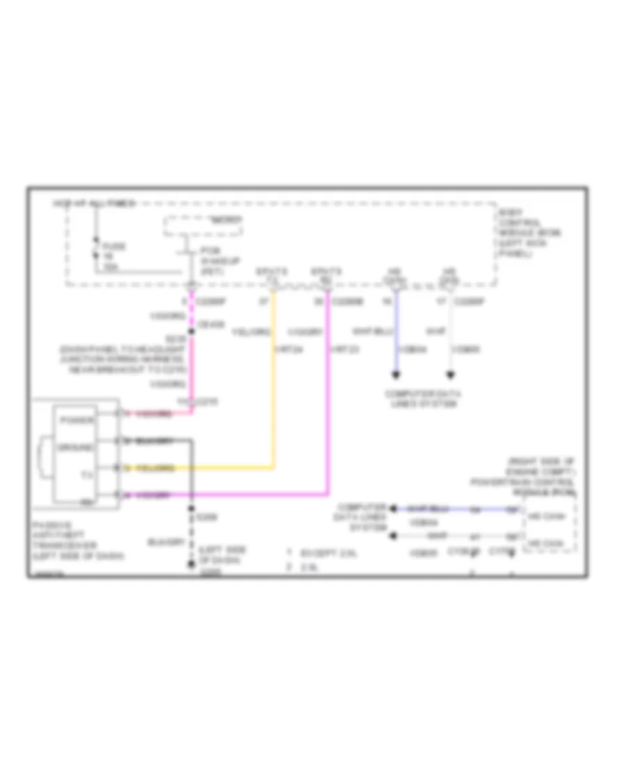
Passive Anti-theft Wiring Diagram, without Intelligent Access for Ford Edge Limited 2013
 https://portal-diagnostov.com/license.html
Automotive Electricians Portal FZCO
Automotive Electricians Portal FZCO
https://portal-diagnostov.com/license.html
https://portal-diagnostov.com/license.html
Automotive Electricians Portal FZCO
Automotive Electricians Portal FZCOList of elements for Passive Anti-theft Wiring Diagram, without Intelligent Access for Ford Edge Limited 2013:
- (left side of dash)
- (right side of engine compt) powertrain control module (pcm)
- 2.0l
- Body control module (bcm) (left kick panel)
- C1381b
- C175b
- C215
- C2280b
- C2280f
- Ce436
- Computer data lines system
- Epats rx
- Epats tx
- Except 2.0l
- Fuse 10a
- G205
- Ground
- Hot at all times
- Hs can+
- Hs can-
- Micro
- Passive anti-theft transceiver (left side of dash)
- Pcm wakeup (fet)
- Power
- S208
- S235 (dash panel to headlight junction wiring harness, near breakout to c215)
- Vdb04
- Vdb05
- Vrt23
- Vrt24
BODY CONTROL MODULES
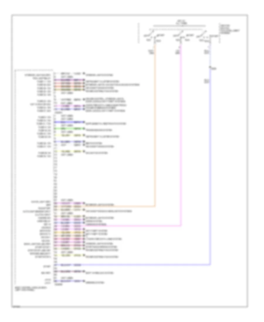
Body Control Modules Wiring Diagram (1 of 2) for Ford Edge Limited 2013
 https://portal-diagnostov.com/license.html
Automotive Electricians Portal FZCO
Automotive Electricians Portal FZCO
https://portal-diagnostov.com/license.html
https://portal-diagnostov.com/license.html
Automotive Electricians Portal FZCO
Automotive Electricians Portal FZCOList of elements for Body Control Modules Wiring Diagram (1 of 2) for Ford Edge Limited 2013:
- (not used)
- Acc
- Acc/run
- Air conditioning & headlights systems
- Air conditioning system
- Anti-theft system
- Autolamp sensor input
- Back lighting led (fet)
- Body control module (bcm) (left kick panel)
- Bpp
- Bsi (fet)
- C2280a
- C2280b
- Cbp35
- Cbp36
- Cbp37
- Cbp41
- Cbp42
- Ccb08
- Cdc30
- Cdc33
- Cdc34
- Cdc35
- Cet53
- Cls32
- Clutch input
- Computer data lines & electronic power steering systems
- Computer data lines system
- Cpk34
- Cpk35
- Cpk36
- Crh04
- Cruise control, interior lights, door locks & anti-theft systems
- Door locks & anti-theft systems
- Epats rx
- Epats tx
- Exterior lights system
- Exterior lights, navigation & sound systems
- Fog lamp relay
- Fuse 11, 10a
- Fuse 23, 15a
- Fuse 24, 15a
- Fuse 26, 5a
- Fuse 27, 20a
- Fuse 28, 15a
- Fuse 29, 20a
- Fuse 31, 5a
- Fuse 32, 15a
- Fuse 34, 10a
- Fuse 35, 5a
- Fuse 36, 10a
- Fuse 37, 10a
- Fuse 38, 10a
- Fuse 41, 7.5a
- Fuse 42, 5a
- Fuse 44, 10a
- Fuse 46, 10a
- Fuse 9, 10a
- Hazard sw
- Horn relay
- Horns system
- Hot at all times
- Hot in run or acc
- Ignition switch (w/o intelligent access)
- Instrument cluster system
- Interior lighting (fet)
- Interior lights system
- Key in
- Lin 01
- Lin 04
- Mirrors system
- Ms can +
- Ms can -
- Navigation system
- Off
- Power distribution system
- Ripcord security
- Run
- Run/start
- S285
- Sbp11
- Sbp23
- Sbp24
- Sbp26
- Sbp27
- Sbp28
- Sbp29
- Sbp46
- Seats system
- Shift interlock system
- Start
- Start/stop 1
- Start/stop 2
- Starting/charging system
- Strt/stop (led) fet
- Transmissions system
- Vdb06
- Vdb07
- Vdn01
- Vlf14
- Vln04
- Vln33
- Vrt23
- Vrt24
- Warning systems
- White light (fet)
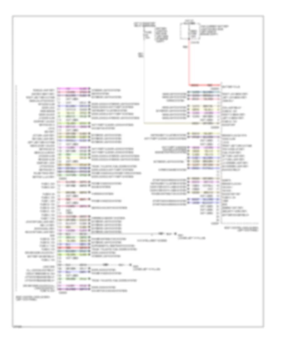
Body Control Modules Wiring Diagram (2 of 2) for Ford Edge Limited 2013
 https://portal-diagnostov.com/license.html
Automotive Electricians Portal FZCO
Automotive Electricians Portal FZCO
https://portal-diagnostov.com/license.html
https://portal-diagnostov.com/license.html
Automotive Electricians Portal FZCO
Automotive Electricians Portal FZCOList of elements for Body Control Modules Wiring Diagram (2 of 2) for Ford Edge Limited 2013:
- (not used)
- 2nd row seat (fet)
- All lock/unlock relay
- Anti-theft & door locks systems
- Anti-theft & engine controls systems engine controls system
- Battery junction box (bjb) (left side of engine compt)
- Battery plus
- Battery saver relay
- Batterysaver relay
- Bcs
- Body control module (bcm) (left kick panel)
- Brake fluid sw
- Brake fluid sw rtn
- Bsi (fet)
- C1617b
- C2280c
- C2280d
- C2280e
- C2280f
- C2280g
- Cbp01
- Cbp30
- Cbp32
- Cbp34
- Cbp40
- Cbp41
- Cdc21
- Cdc55
- Cdc64
- Ce226
- Ce436
- Circuit breaker 48, 30a
- Clf02
- Clf03
- Clf04
- Clf05
- Clf06
- Clf07
- Clf12
- Cln09
- Cln25
- Cls18
- Cls19
- Cls21
- Cls23
- Cls25
- Cls27
- Cls28
- Cls52
- Cls54
- Cls55
- Cmc19
- Cmc25
- Computer data lines system
- Cpk19
- Cpk23
- Cpk28
- Cpk29
- Cpk30
- Cpk31
- Cpl11
- Cpl25
- Cpl26
- Cpl31
- Cpl36
- Cpl39
- Cpl45
- Cpl51
- Cpl52
- Cpl58
- Cpl84
- Cps45
- Cpw01
- Decklid ajar sw
- Decklid key unlock
- Decklid/liftgate sw
- Door key lock
- Door key unlock
- Door lock
- Door locks & anti-theft systems
- Door locks & interior lights systems
- Door locks system
- Door unlock
- Driver door unlock & all lock/unlock rly fuse 19, 20a
- Driver door unlock rly
- Energy mgt (fet)
- Exterior lights system
- Fog lamp relay
- Front led turn outage
- Fuel pump (fet)
- Fuse 1, 30a
- Fuse 2, 15a
- Fuse 21, 10a
- Fuse 3, 30a
- Fuse 30, 15a
- Fuse 30a
- Fuse 31, 5a
- Fuse 32, 15a
- Fuse 33, 10a
- Fuse 34, 10a
- Fuse 4, 10a
- Fuse 40, 10a
- Fuse 41, 7.5a
- Fuse 43, 10a
- Fuse 5, 20a
- Fuse 6, 5a
- Fuse 7, 7.5a
- Fuse 8, 10a
- Fuse 9, 10a
- G200 (lower left "a" pillar)
- G201 (lower left "a" pillar)
- Gd133
- Gnd
- Headlights system
- High current battery junction box (bjb) (left side of engine compt)
- Hood ajar
- Horn rly
- Horns system
- Hot at all times
- Hot w/ run/start relay energized
- Hs can +
- Hs can -
- Instrument cluster system
- Interior lights system
- Keypad illum (fet)
- Keypad sw a
- Keypad sw b
- Keypad sw c
- Ldc59
- Left hi beam (fet)
- Left led turn outage
- Left low beam (fet)
- Lf door ajar
- Lf turn lamp (fet)
- Lh corner lamp (fet)
- Liftgate release relay
- Liftgate sw
- Lin 02
- Lin 03
- Logic gnd
- Lr door ajar
- Lr stop/turn lamp (fet)
- Lr turn lamp (fet)
- Mega fuse 120a
- Mirrors & memory systems
- Navigation & sound systems
- Navigation system
- Park brake
- Pcm wake up (fet)
- Power distribution system
- Power windows & power tops systems
- Power windows system
- Puddle lamp (fet)
- Pulse train (fet)
- Rdc59
- Red
- Rev lp (fet)
- Rf door ajar
- Rf turn lamp (fet)
- Rh corner lamp (fet)
- Right hi beam (fet)
- Right led turn outage
- Right low beam (fet)
- Rmc19
- Rr door ajar
- Rr stop/turn lamp (fet)
- Rr turn lamp (fet)
- Run/acc relay
- Run/start
- Run/start fet
- S200
- S201
- Sbp01
- Sbp03
- Sbp05
- Sbp06
- Sbp07
- Sbp09
- Sbp19
- Sdc02
- Sdc57
- Seats & navigation systems
- Seats system
- Security horn (fet)
- Sigrtn
- Sound systems
- Srh01
- Starting/charging system
- Stop/chmsl (fet)
- Trunk, tailgate, fuel doors system
- Vdb04
- Vdb05
- Vdn03
- Vref
- W/o intelligent access
- Warning systems
- Wiper/washer system
COMPUTER DATA LINES
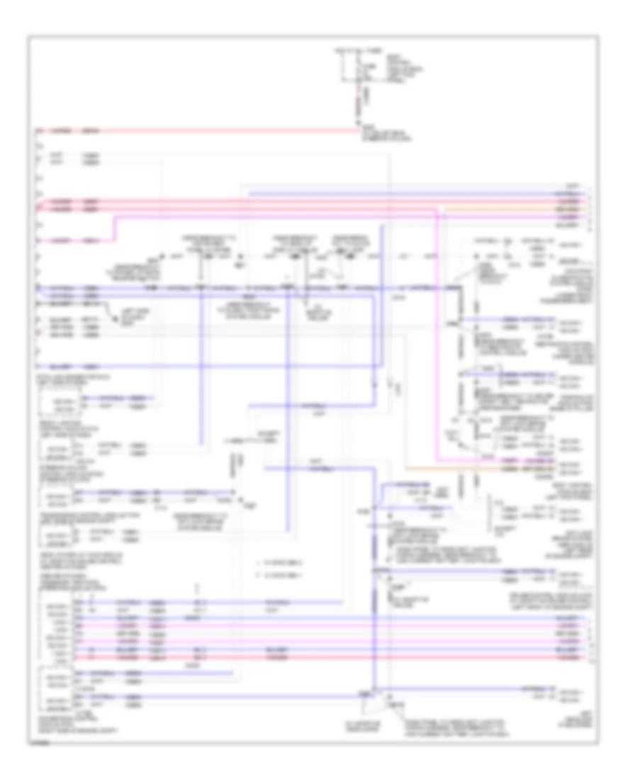
Computer Data Lines Wiring Diagram (1 of 2) for Ford Edge Limited 2013
 https://portal-diagnostov.com/license.html
Automotive Electricians Portal FZCO
Automotive Electricians Portal FZCO
https://portal-diagnostov.com/license.html
https://portal-diagnostov.com/license.html
Automotive Electricians Portal FZCO
Automotive Electricians Portal FZCOList of elements for Computer Data Lines Wiring Diagram (1 of 2) for Ford Edge Limited 2013:
- (center of dash) accessory protocol interface module (apim)
- (dash panel to headlight junction wiring harness, near breakout to high current battery junction box)
- (left side of dash) g205
- (near break- out to glove box lamp)
- (near breakout to anti-lock brake system module)
- (near breakout to global positioning system module)
- (near breakout to head up display module)
- (near breakout to instrument panel cluster)
- (near breakout to restraints control module)
- (not used)
- (w/ adaptive cruice)
- (w/ adaptive headlamps)
- (w/ sync)
- 2.0l
- Anti-lock brake system (abs) module (left rear of engine compt)
- Body control module (bcm) (left kick panel)
- C110
- C1381b
- C175b
- C212
- C215
- C219
- C2280a
- C2280b
- C2280f
- C2414a
- C3053
- C310b
- C314
- Cruise-control module (c-cm) (w/ adaptive cruise control) (left front of engine compt)
- Data link connector (dlc) (left side of dash)
- Except 2.0l
- Front lighting control module (flm) (left side of dash)
- Fuse 15a
- Gd115
- Head up display (hud) module (w/ adaptive cruise control) (center of dash)
- Hot at all times
- Hs can +
- Hs can -
- I can +
- I can -
- Left headlamp (if equipped)
- Ms can +
- Ms can -
- Occupant classification system module (ocsm) (under front passenger's seat)
- Parking aid module (pam) (base "d" pillar)
- Powertrain control module (pcm) (right side of engine compt)
- Restraints control module (rcm) (under center console)
- S102
- S103
- S104
- S105
- S106
- S107
- S140
- S141
- S205 (near breakout to power liftgate release switch)
- S206
- S210
- S211
- S220
- S221
- S224
- S225
- S226
- S227
- S228 (w/ adjustable steering column)
- S304
- S355 (near breakout to c314)
- S358
- Sbp24
- Steering column control module (sccm) (steering column)
- System module)
- Transmission control module (tcm) (left side of engine compt)
- Vdb04
- Vdb05
- Vdb06
- Vdb07
- Vdb13
- Vdb14
- W/ sync gen 1
- W/ sync gen 2
Computer Data Lines Wiring Diagram (2 of 2) for Ford Edge Limited 2013
 https://portal-diagnostov.com/license.html
Automotive Electricians Portal FZCO
Automotive Electricians Portal FZCO
https://portal-diagnostov.com/license.html
https://portal-diagnostov.com/license.html
Automotive Electricians Portal FZCO
Automotive Electricians Portal FZCOList of elements for Computer Data Lines Wiring Diagram (2 of 2) for Ford Edge Limited 2013:
- (near breakout to accessory protocol interface module)
- (near breakout to audio control module)
- (near breakout to audio control module) s262
- (near breakout to power point (instrument)) (w/ sync gen 1) s246
- (under driver's seat)
- (w/ sync gen 1) s247
- Audio control module (acm) (center of dash)
- Audio digital signal processing (dsp) module (w/ premium amplifier) (right "c" pillar)
- C213
- C214
- C2153e
- C219
- C228a
- C240a
- C3036c
- C311
- C316
- C3299d
- C4174b
- C4326a
- C4348a
- Datc hvac module (automatic a/c)
- Driver seat module (dsm) (w/ memory)
- Dual climate controlled seat module (dcsm) (w/ climate controlled seats)
- Edge w/ sony audio
- Emtc hvac module (manual a/c)
- Front control interface module (fcim) (center of dash)
- Front control/ display interface module (fcdim) (w/o sync gen 2) (center of dash)
- Global positioning system module (gpsm) (w/ sync) (top center of dash)
- Heated steering wheel module (hswm) (right side of dash)
- Hs can +
- Hs can -
- I can +
- I can -
- Instrument panel cluster (ipc)
- Left side obstacle detection control module (sod-l) (w/ blindspot information system) (rear of vehicle)
- Liftgate/trunk module (ltm) (base of left "d" pillar)
- Mkx w/ thx audio
- Ms can +
- Ms can -
- Remote function actuator (rfa) module (w/ intelligent access) (behind glove box)
- Right side obstacle detection control module (sod-r) (w/ blindspot information system) (rear of vehicle)
- S256 (near breakout to c237) s257
- S258
- S259
- S260
- S261
- S263
- S310 (near breakout to c314)
- S325 (near breakout to passenger c-pillar side impact sensor)
- S336
- S345
- S346 (near breakout to driver c-pillar side impact sensor)
- S377
- S378 (near breakout to c3142)
- S379 (w/ premium amplifier)
- S380 (w/ premium amplifier) (near breakout to passenger c-pillar side impact sensor)
- S404 (near breakout to rear power seat release switch)
- S406
- Tire pressure monitor (tpm) module (left "c" pillar)
- Vdb06
- Vdb07
- Vdb13
- Vdb14
- W/ premium amplifier
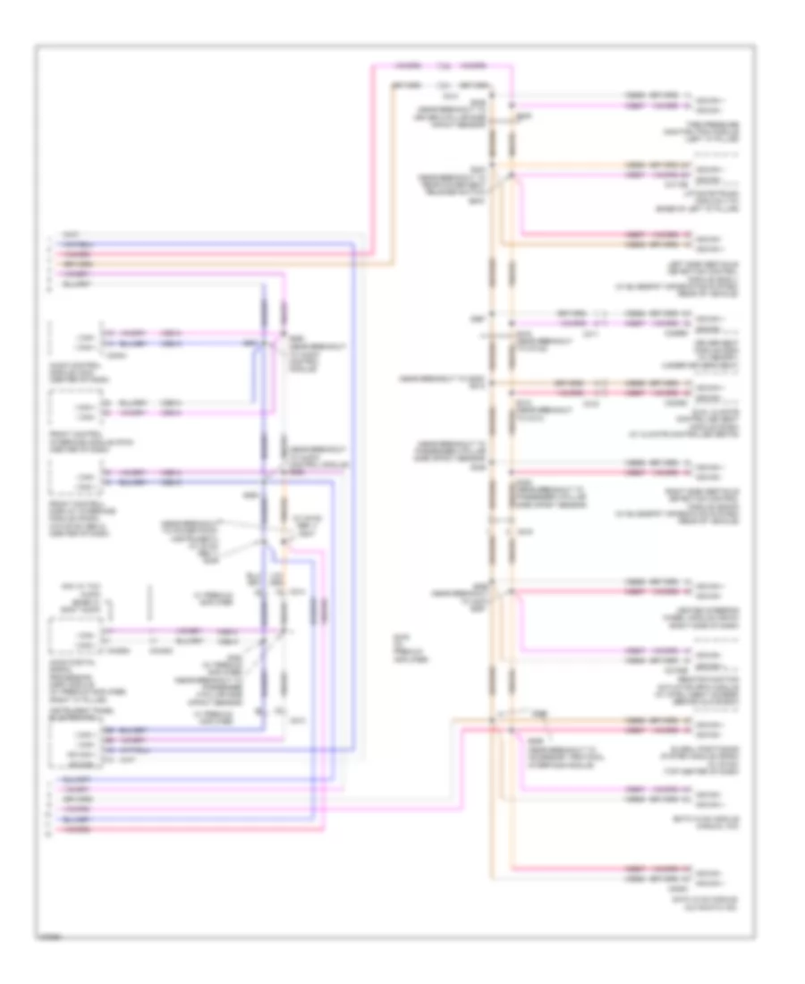
COOLING FAN
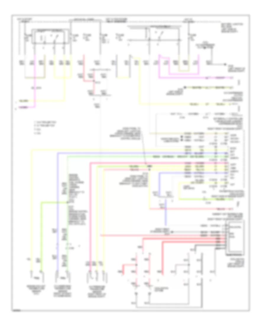
Cooling Fan Wiring Diagram, with Trailer Tow for Ford Edge Limited 2013
 https://portal-diagnostov.com/license.html
Automotive Electricians Portal FZCO
Automotive Electricians Portal FZCO
https://portal-diagnostov.com/license.html
https://portal-diagnostov.com/license.html
Automotive Electricians Portal FZCO
Automotive Electricians Portal FZCOList of elements for Cooling Fan Wiring Diagram, with Trailer Tow for Ford Edge Limited 2013:
- Battery junction box (bjb) (left side of engine compt)
- C175b
- C175e
- C192
- Cht
- Cooling fan
- Cooling fan module (left front of engine compt)
- Cylinder head temperature (cht) sensor (front of right cylinder bank)
- Electronics
- Fan control variable
- Fuse 40a
- G107 (right front of engine compt)
- Gnd
- Hot at all times
- Powertrain control module (pcm) (right side of engine compt)
- Pwr
- Re405
- Red
- S112
- S127 (engine control sensor & fuel charge wiring harness, near breakout to coil on plug 3)
- Sigrtn
- Ve712
- Veco3
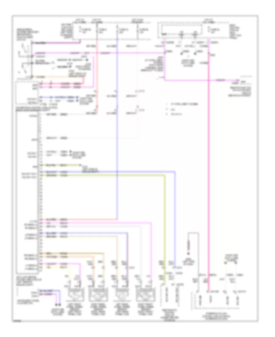
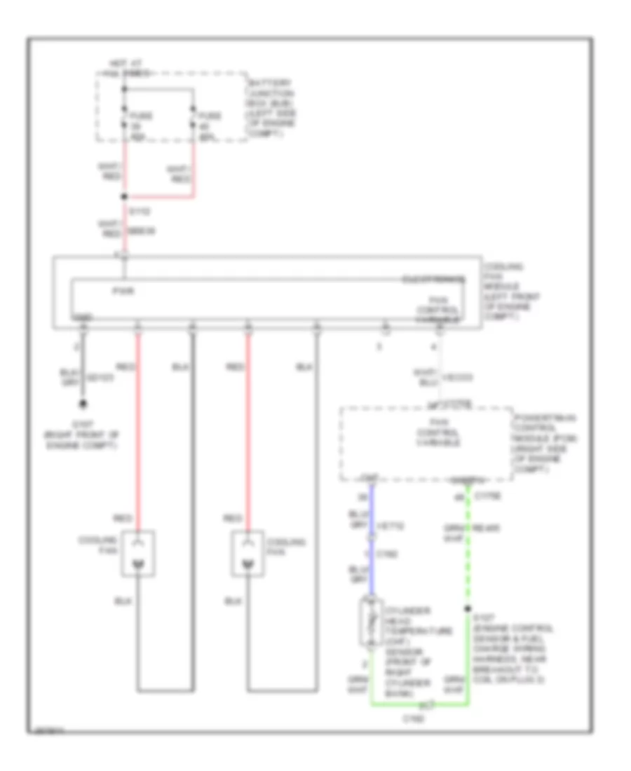
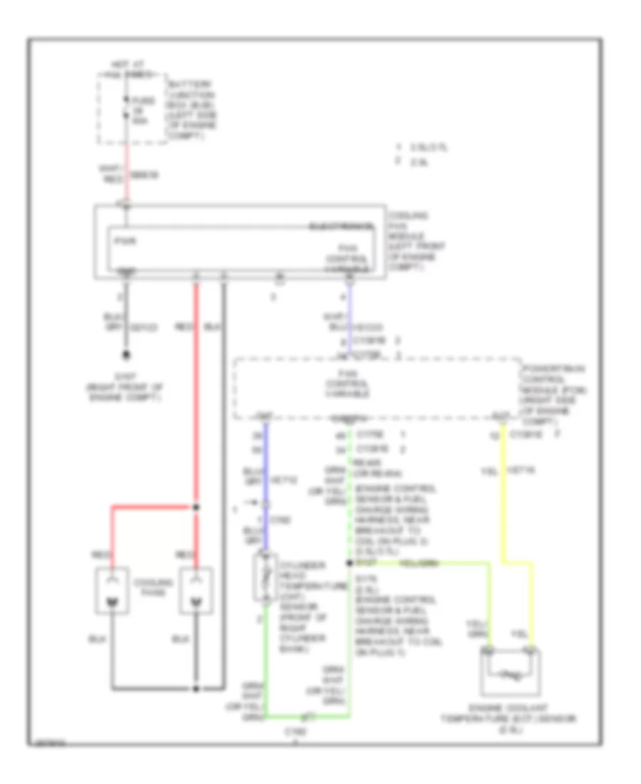
Cooling Fan Wiring Diagram, without Trailer Tow for Ford Edge Limited 2013
 https://portal-diagnostov.com/license.html
Automotive Electricians Portal FZCO
Automotive Electricians Portal FZCO
https://portal-diagnostov.com/license.html
https://portal-diagnostov.com/license.html
Automotive Electricians Portal FZCO
Automotive Electricians Portal FZCOList of elements for Cooling Fan Wiring Diagram, without Trailer Tow for Ford Edge Limited 2013:
- (engine control sensor & fuel charge wiring harness, near breakout to coil on plug 3) (3.5l/3.7l) s127
- 2.0l
- 3.5l/3.7l
- Battery junction box (bjb) (left side of engine compt)
- C1381b
- C1381e
- C175b
- C175e
- C192
- Cht
- Cooling fan module (left front of engine compt)
- Cooling fans
- Cylinder head temperature (cht) sensor (front of right cylinder bank)
- Ect
- Electronics
- Engine coolant temperature (ect) sensor (2.0l)
- Fan control variable
- Fuse 60a
- G107 (right front of engine compt)
- Gnd
- Hot at all times
- M m
- Powertrain control module (pcm) (right side of engine compt)
- Pwr
- Red
- S176 (2.0l) (engine control sensor & fuel charge wiring harness, near breakout to coil on plug 1)
- Sigrtn
- Veco3
CRUISE CONTROL
Cruise Control Wiring Diagram (1 of 2) for Ford Edge Limited 2013
 https://portal-diagnostov.com/license.html
Automotive Electricians Portal FZCO
Automotive Electricians Portal FZCO
https://portal-diagnostov.com/license.html
https://portal-diagnostov.com/license.html
Automotive Electricians Portal FZCO
Automotive Electricians Portal FZCOList of elements for Cruise Control Wiring Diagram (1 of 2) for Ford Edge Limited 2013:
- (behind glove box) remote function actuator (rfa) module
- A/d 2
- A/d 3
- A/d 4
- Body control module (bcm) (left kick panel)
- Bpp
- C215
- C2153c
- C218b
- C218c
- C2280a
- C2280b
- C2280f
- C2414a
- C2414b
- C2414d
- Cbp35
- Clock spring (steering column)
- Computer data lines system
- Fuse 11 10a
- Fuse 23 15a
- Fuse 24 15a
- Fuse 35 5a
- G205 (left side of dash)
- Gap+ (w/ adaptive cruise control) off (w/o adaptive cruise control)
- Gap- (w/ adaptive cruise control) on (w/o adaptive cruise control)
- Gd115
- Gnd
- Head up display (hud) module (w/ adaptive cruise control) (center of dash)
- Hot at all times
- Hot in start or run
- Hs can +
- Hs can -
- Hs can+
- Hs can-
- Instrument panel cluster (ipc)
- Interior lights system
- Isp-r
- Left steering wheel switch
- Lf sw gnd
- Logic gnd
- Micro
- Nca
- On/off (w/ adaptive cruise control) cancel (w/o adaptive cruise control)
- Pwr gnd
- Res/cncl (w/ adaptive cruise control) resume (w/o adaptive cruise control)
- S214
- S228
- S229
- S267 (main wiring harness, near breakout to g205)
- S294 (steering wheel jumper wiring harness)
- S295 (steering wheel jumper wiring harness)
- S296 (steering wheel jumper wiring harness)
- Sbp11
- Sbp23
- Sbp24
- Set+
- Set-
- Sound systems
- Steering column control module (sccm) (steering column)
- Vbatt
- Vdb04
- Vdb05
- W/ adjustable steering column
- W/ intelligent access
Cruise Control Wiring Diagram (2 of 2) for Ford Edge Limited 2013
 https://portal-diagnostov.com/license.html
Automotive Electricians Portal FZCO
Automotive Electricians Portal FZCO
https://portal-diagnostov.com/license.html
https://portal-diagnostov.com/license.html
Automotive Electricians Portal FZCO
Automotive Electricians Portal FZCOList of elements for Cruise Control Wiring Diagram (2 of 2) for Ford Edge Limited 2013:
- (battery cable wiring harness, near breakout to 6f35 transmission) s183
- (w/ adaptive cruise control)
- 2.0l
- 6f35 transmission (2.0l)
- 6f50 transmission (except 2.0l)
- Accelerator pedal position (app) sensor (top of accelerator pedal)
- App1
- App2
- Apprtn
- Apprtn2
- Appvref
- Appvref2
- Battery junction box (bjb) (left side of engine compt)
- Bpp
- Bps
- Brake pedal position (bpp) switch (brake pedal support bracket)
- C1381b
- C1381e
- C1520a
- C1520b
- C175b
- C175e
- C175t
- Case gnd
- Cbb90
- Cbb91
- Ccb08
- Ce412
- Ce426
- Ces09
- Computer data lines system
- Cruise control module (ccm)
- Electronic throttle control (etc) motor (throttle body)
- Etcref
- Etcrtn
- Except 2.0l
- Fuse 59 10a
- Fuse 79 5a
- Fuse 86 7.5a
- Fuse 90 10a
- Fuse 91 10a
- G105 (left front of engine compt)
- G109 (right front of engine)
- Gd120
- Gd124
- Gnd
- Hot at all times
- Hot in start or run
- Hs can +
- Hs can -
- Hs can+
- Hs can-
- Isp-r
- Kapwr
- Le111
- Le134
- Le136
- Le137
- Oss
- Oss/tr gnd
- Oss/tr vpwr
- Power distribution system
- Powertrain control module (pcm) (right side of engine compt)
- Re134
- Re136
- Re137
- Ret24
- S111 (dash panel to headlight junction wiring harness, near breakout to c134)
- S120
- S120 (2.0l)
- S184 (battery cable wiring harness, near breakout to transmission control module)
- Sbb79
- Sbb86
- Tacm+
- Tacm-
- Tp1
- Tp2
- Tr gnd
- Transmission control module (2.0l) (left side of engine compt)
- Trgnd tss/oss/
- Tss
- Tss gnd
- Tss pwr
- Tss/oss gnd
- Tss/oss vpwr
- Tss/oss/tr gnd
- Vbatt
- Vbdo4
- Vbdo5
- Vdb04
- Vdb05
- Ve701
- Ve702
- Ve818
- Ve819
- Vet26
- Vet33
- Vpwr tss/oss/
DEFOGGERS
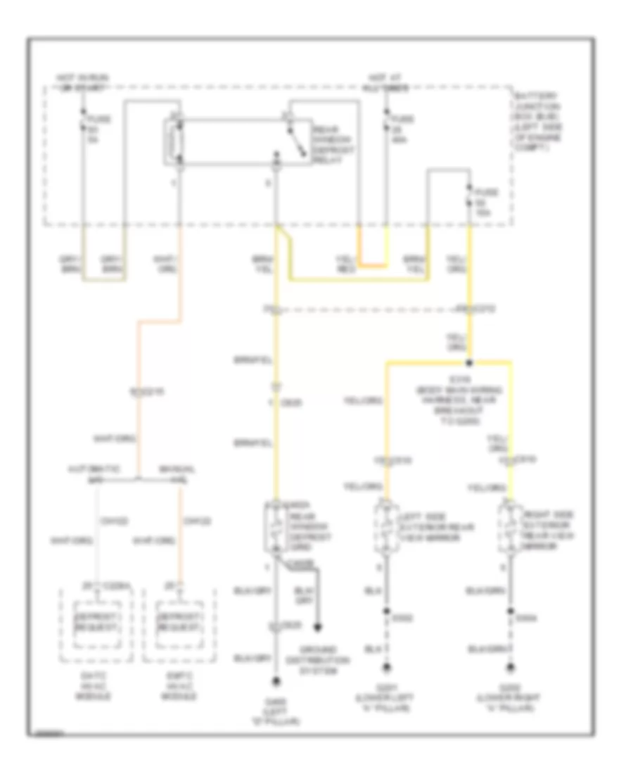
Defoggers Wiring Diagram for Ford Edge Limited 2013
 https://portal-diagnostov.com/license.html
Automotive Electricians Portal FZCO
Automotive Electricians Portal FZCO
https://portal-diagnostov.com/license.html
https://portal-diagnostov.com/license.html
Automotive Electricians Portal FZCO
Automotive Electricians Portal FZCOList of elements for Defoggers Wiring Diagram for Ford Edge Limited 2013:
- Automatic a/c
- Battery junction box (bjb) (left side of engine compt)
- C212
- C215
- C228a
- C402a
- C402b
- C510
- C610
- C925
- Ch122
- Datc hvac module
- Defrost request
- Emtc hvac module
- Fuse 15a
- Fuse 40a
- Fuse 5a
- G201 (lower left "a" pillar)
- G202 (lower right "a" pillar)
- G400 (left "d" pillar)
- Ground distribution system
- Hot at all times
- Hot in run or start
- Left side exterior rear view mirror
- Manual a/c
- Rear window defrost grid
- Rear window defrost relay
- Right side exterior rear view mirror
- S316 (body main wiring harness, near breakout to g200)
- S502
- S604
ELECTRONIC POWER STEERING
Electronic Power Steering Wiring Diagram for Ford Edge Limited 2013
 https://portal-diagnostov.com/license.html
Automotive Electricians Portal FZCO
Automotive Electricians Portal FZCO
https://portal-diagnostov.com/license.html
https://portal-diagnostov.com/license.html
Automotive Electricians Portal FZCO
Automotive Electricians Portal FZCOList of elements for Electronic Power Steering Wiring Diagram for Ford Edge Limited 2013:
- (main wiring harness, near breakout to adjustable steering column motor (telescope)) s292
- A/d 1
- A/d 2
- A/d 3
- A/d 4
- Body control module (bcm) (left kick panel)
- C2280a
- C2414a
- C2414b
- C2414c
- C2414d
- Cet42
- Cet43
- Computer data lines system
- Cpp02
- Cpp04
- Cpp22
- Crh04
- Cruise control system
- Cruise control, navigation & sound systems
- Crw15
- Down
- Frt wiper hi
- Fuse 15a
- G205 (left side of dash)
- Gd115
- Horn
- Horn sw
- Horns system
- Hot at all times
- Hs can+
- Hs can-
- Lin
- Logic gnd
- Mtr com
- Multi-function switch
- Nca
- Pwr gnd
- Re407
- Rpp06
- S228
- S229
- S293 (main wiring harness, near breakout to adjustable steering column motor (telescope))
- Sbp23
- Sbp24
- Sig
- Sns rtn
- Sound & navigation systems
- Steering column control module (sccm) (steering column)
- Sw gnd left
- Sw gnd right
- Sw rtn
- Tel mtr+/-
- Tel sns+
- Telescope adjustable steering column motor (steering column)
- Tilt adjustable steering column motor (steering column)
- Tilt mtr+/-
- Tilt sns+
- Transmissions system
- Vbatt
- Vdb04
- Vdb05
- Vdn05
- Vpp08
- Vpp17
- Wiper/washer system
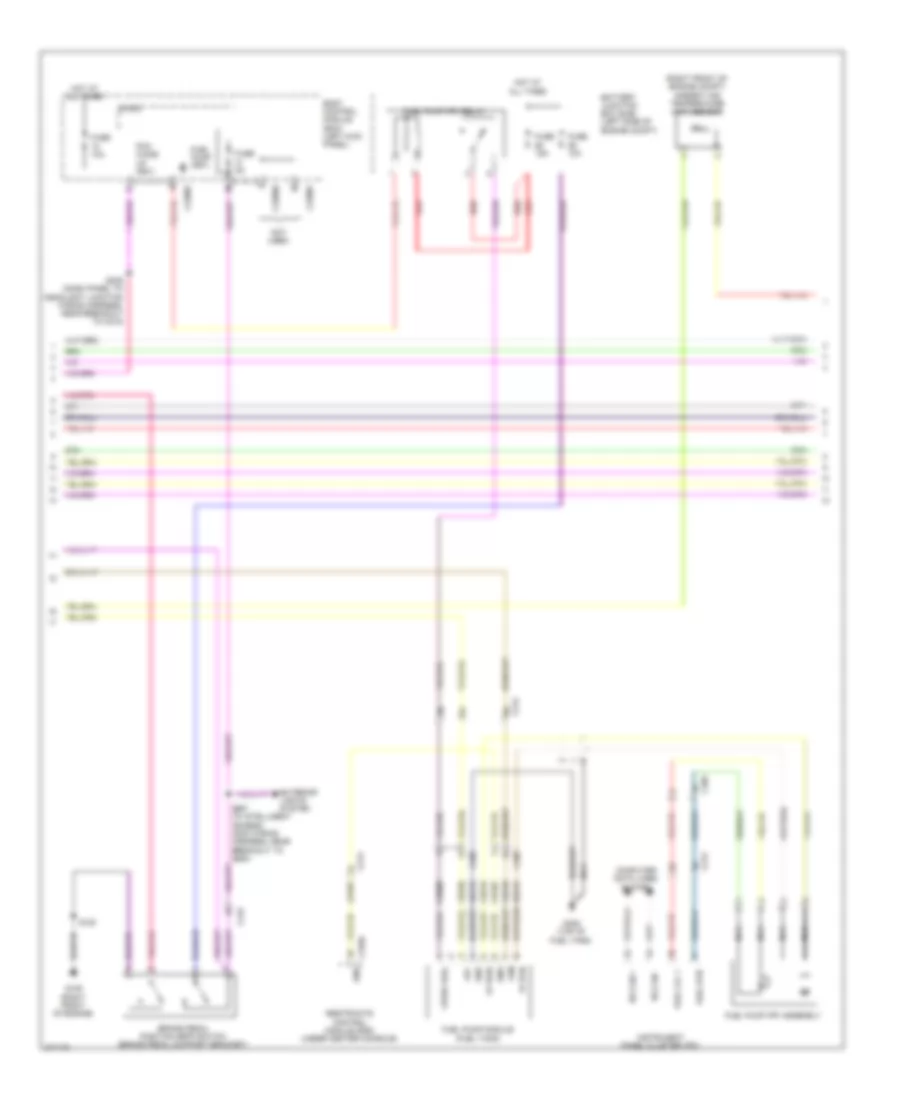
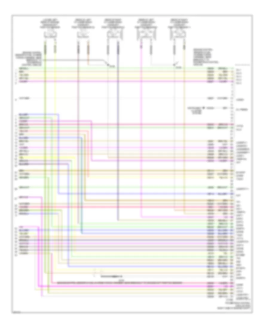
ENGINE PERFORMANCE
2.0L
2.0L, Engine Performance Wiring Diagram (1 of 5) for Ford Edge Limited 2013
 https://portal-diagnostov.com/license.html
Automotive Electricians Portal FZCO
Automotive Electricians Portal FZCO
https://portal-diagnostov.com/license.html
https://portal-diagnostov.com/license.html
Automotive Electricians Portal FZCO
Automotive Electricians Portal FZCOList of elements for 2.0L, Engine Performance Wiring Diagram (1 of 5) for Ford Edge Limited 2013:
- Aat
- Accelerator pedal position (app) sensor (top of accelerator pedal)
- Accr
- Acpt
- Air conditioning system
- App1
- App2
- Apprtn
- Apprtn2
- Appvref
- Appvref2
- Battery junction box (bjb) (left side of engine compt)
- Bcs2alt
- Bpp
- Bps
- C1381b
- C140
- C212
- Canv
- Cbb69
- Cbb90
- Ccb08
- Cdc12
- Cdc15
- Cdc26
- Cdc35
- Ce114
- Ce233
- Ce237
- Ce436
- Ces09
- Cet40
- Ch302
- Computer data lines system
- Cooling fans system
- Evap canister vent control solenoid (under left side of vehicle)
- Evapcp diode
- Fcv
- Fpc
- Fpm
- Fuse 10a
- Fuse 15a
- Fuse 20a
- Fuse 7.5a
- G109 (right front of engine)
- Gd124
- Genmon
- Heated oxygen sensor (ho2s) 12 (right front of engine, on exhaust)
- Ho2s12
- Hot at all times
- Hot in start or run
- Hs can+
- Hs can-
- Htr12
- Isp-r
- Le136
- Le137
- Le230
- Le424
- Nca
- Pcm power relay
- Pcm wake
- Pcmrc
- Power distribution system
- Powertrain control module (pcm) (right side of engine compt)
- Pwr gnd
- Re136
- Re137
- Re407
- S108
- S118
- S120
- Sigrtn
- Smc
- Smcs
- Start
- Starting/charging system
- Transmissions system
- Trsw-pn
- Vdb04
- Vdb05
- Vdc61
- Ve225
- Ve518
- Ve701
- Ve702
- Ve731
- Vec03
- Vh407
- Vh433
- Vpwr
- Vref
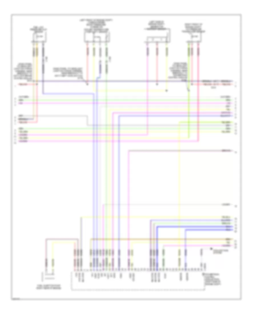
2.0L, Engine Performance Wiring Diagram (2 of 5) for Ford Edge Limited 2013
 https://portal-diagnostov.com/license.html
Automotive Electricians Portal FZCO
Automotive Electricians Portal FZCO
https://portal-diagnostov.com/license.html
https://portal-diagnostov.com/license.html
Automotive Electricians Portal FZCO
Automotive Electricians Portal FZCOList of elements for 2.0L, Engine Performance Wiring Diagram (2 of 5) for Ford Edge Limited 2013:
- (right front of engine compt) ambient air temperature (aat) sensor
- Battery junction box (bjb) (left side of engine compt)
- Body control module (bcm) (left kick panel)
- Brake pedal position (bpp) switch (brake pedal support bracket)
- C212
- C213
- C215
- C2280b
- C2280f
- C310a
- C405
- Ce515
- Ce608
- Computer data lines system
- Cr167
- Ens
- Exterior lights system
- Fp pwr
- Fp rtn
- Fpc
- Fpm
- Fuel lvl 1
- Fuel pump (fet)
- Fuel pump (fp) assembly
- Fuel pump (fp) relay
- Fuel pump module (fuel tank)
- Fuel rtn
- Fuse 10a
- Fuse 15a
- Fuse 5a
- G109 (right front of engine)
- G405 (top of fuel tank)
- Gd476
- Gnd
- Hot at all times
- Hs can +
- Hs can -
- Instrument panel cluster (ipc)
- Micro
- Nca
- Not used
- Pcm wake up (fet)
- Re515
- Red
- Restraints control module (rcm) (under center console)
- S120
- S235 (dash panel to headlight junction wiring harness, near breakout to c215)
- S267 (w/ intelligent access) (main wiring harness, near breakout to g205)
- Ve225
- Ve518
- Vpwr fuel
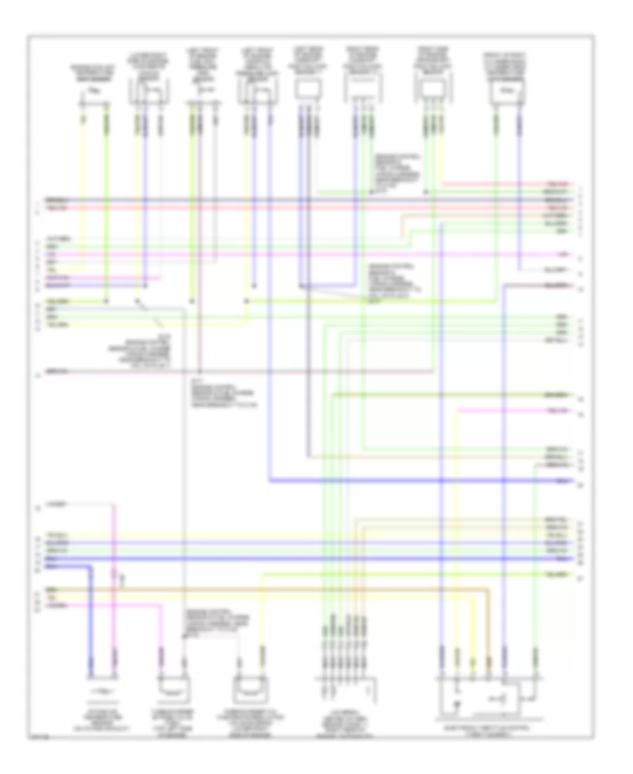
2.0L, Engine Performance Wiring Diagram (3 of 5) for Ford Edge Limited 2013
 https://portal-diagnostov.com/license.html
Automotive Electricians Portal FZCO
Automotive Electricians Portal FZCO
https://portal-diagnostov.com/license.html
https://portal-diagnostov.com/license.html
Automotive Electricians Portal FZCO
Automotive Electricians Portal FZCOList of elements for 2.0L, Engine Performance Wiring Diagram (3 of 5) for Ford Edge Limited 2013:
- (dash panel to headlight junction wiring harness, near breakout to anti-lock brake system module) s142
- (dash panel to headlight junction wiring harness, near breakout to anti-theft hood switch) s119
- (dash panel to headlight junction wiring harness, near breakout to powertrain control module) s122
- (left front of engine compt) turbocharger boost pressure/ charge air cooler temperature (tcbp/cact) sensor
- (left side of engine compt) generator current sensor
- (right front of engine compt) a/c pressure transducer sensor
- C1381e
- C140
- C212
- Cact
- Ce226
- Cooling fans system
- Ect
- Etcref
- Frp
- Fuel injection pump (right rear of engine)
- Fuel low pressure (flp) sensor
- Fvr
- Fvr rtn
- Iat
- Inj1 rtn
- Inj2 rtn
- Inj3 rtn
- Inj4 rtn
- Le134
- Le238
- Le423
- Le458
- Lin
- Powertrain control module (pcm) (right side of engine compt)
- Re205
- Re206
- Re207
- Re208
- Re226
- Re320
- Re454
- Sigrtn
- Tcbp
- Tcby
- Tp1
- Vdb10
- Ve716
- Ve727
- Ve740
- Ve803
- Ve804
- Ve818
- Ve821
- Ve836
- Vref
- Wvs
2.0L, Engine Performance Wiring Diagram (4 of 5) for Ford Edge Limited 2013
 https://portal-diagnostov.com/license.html
Automotive Electricians Portal FZCO
Automotive Electricians Portal FZCO
https://portal-diagnostov.com/license.html
https://portal-diagnostov.com/license.html
Automotive Electricians Portal FZCO
Automotive Electricians Portal FZCOList of elements for 2.0L, Engine Performance Wiring Diagram (4 of 5) for Ford Edge Limited 2013:
- (engine control sensor & fuel charge wiring harness, near breakout to c140) s170
- (engine control sensor & fuel charge wiring harness, near breakout to c140) s172
- (engine control sensor & fuel charge wiring harness, near breakout to coil on plug 3) s177
- (front of right cylinder bank) cylinder head temperature (cht) sensor
- (left front of engine) fuel rail pressure (frp) sensor
- (left front of engine) manifold absolute pressure (map) sensor
- (left rear of engine) camshaft position (cmp) sensor 11
- (lower right side of engine) wastegate vacuum sensor
- (right rear of engine) camshaft position (cmp) sensor 12
- (right side of engine) crankshaft position (ckp) sensor
- C140
- Electronic throttle control (throttle body)
- Engine coolant temperature (ect) sensor
- Intake air temperature sensor (on intake air duct)
- Nca
- S171 (engine control sensor & fuel charge wiring harness, near breakout to c140)
- S176 (engine control sensor & fuel charge wiring harness, near breakout to coil on plug 1)
- Turbocharger (tc) wastegate regulating valve solenoid (lower right side of engine)
- Turbocharger bypass valve (tcbv) (top left side of engine)
- Universal heated oxygen sensor (ho2s) 11 (right rear of engine, on exhaust)
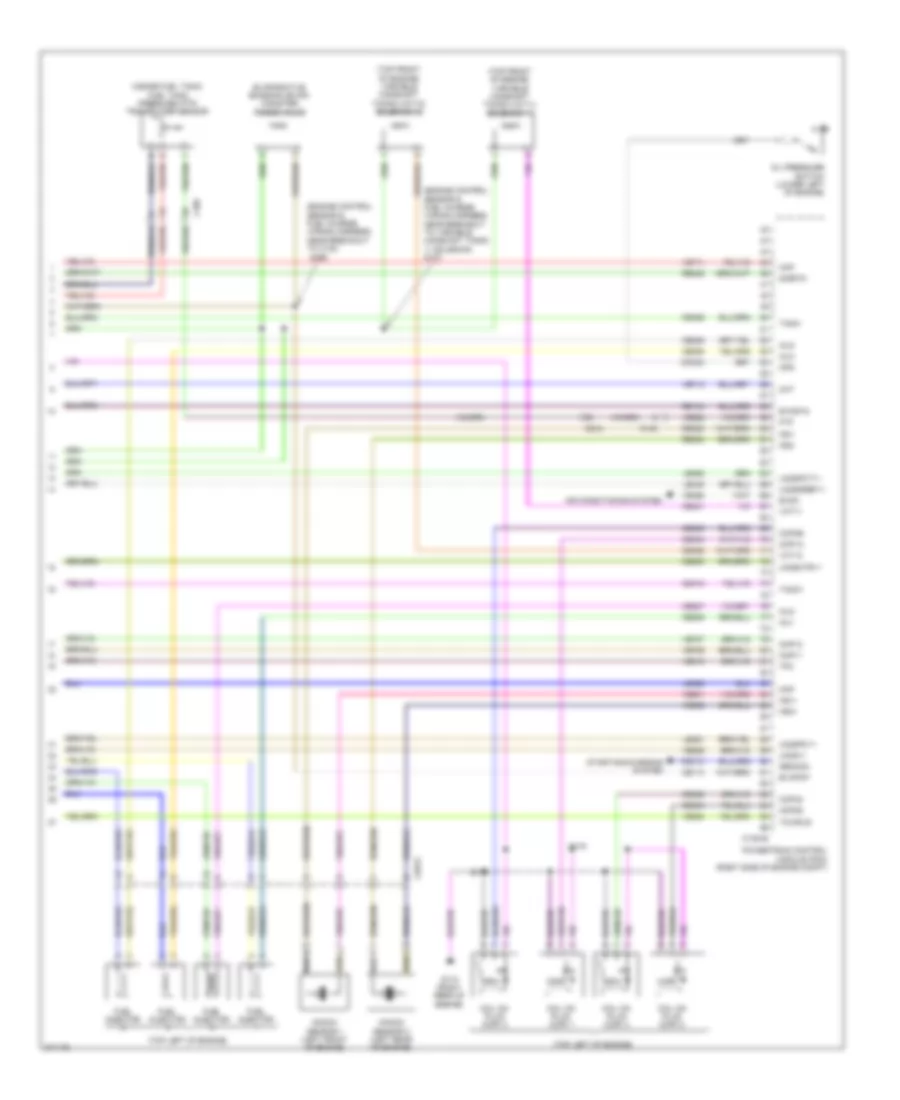
2.0L, Engine Performance Wiring Diagram (5 of 5) for Ford Edge Limited 2013
 https://portal-diagnostov.com/license.html
Automotive Electricians Portal FZCO
Automotive Electricians Portal FZCO
https://portal-diagnostov.com/license.html
https://portal-diagnostov.com/license.html
Automotive Electricians Portal FZCO
Automotive Electricians Portal FZCOList of elements for 2.0L, Engine Performance Wiring Diagram (5 of 5) for Ford Edge Limited 2013:
- (engine control sensor & fuel charge wiring harness, near breakout to c140)
- (engine control sensor & fuel charge wiring harness, near breakout to variable camshaft timing 11 solenoid) s173
- (inside fuel tank) fuel tank pressure (ftp) transducer sensor
- (top front of engine) variable camshaft timing (vct11) solenoid 11
- (top front of engine) variable camshaft timing (vct12) solenoid 12
- (top left of engine)
- Air conditioning system
- C1033
- C1381e
- C140
- C212
- C405
- Cdc10
- Ce113
- Ce205
- Ce206
- Ce207
- Ce208
- Ce235
- Ce303
- Ce304
- Ce305
- Ce306
- Ce412
- Ce421
- Ce422
- Ce426
- Cht
- Ckp
- Cmc24
- Cmp11
- Cmp12
- Coil on plug (cop) 1
- Coil on plug (cop) 2
- Coil on plug (cop) 3
- Coil on plug (cop) 4
- Cop1a
- Cop2d
- Cop3b
- Cop4c
- Etcrtn
- Evapcp
- Evaporative emission (evap) canister purge valve
- Evdc
- Ftp
- Fuel injector
- G110 (right rear of engine)
- Gencom
- Inj1
- Inj2
- Inj3
- Inj4
- Knock sensor 1 (left front of engine)
- Knock sensor 2 (left rear of engine)
- Ks1+
- Ks1-
- Ks2+
- Ks2-
- Le329
- Le448
- Le451
- Le452
- Map
- Oil pressure switch (lower left of engine)
- Ops
- Powertrain control module (pcm) (right side of engine compt)
- Re134
- Re323
- Re324
- Re405
- S169
- S174
- S175
- Sigrtn
- Starting/charging system
- Tacm+
- Tacm-
- Tcwrvs
- Tp2
- Uo2s11
- Uo2sgref11
- Uo2shtr11
- Uo2spc11
- Uo2spct11
- Vct11
- Vct12
- Ve462
- Ve706
- Ve707
- Ve711
- Ve712
- Ve801
- Ve802
- Ve819
- Ve824
- Ve826
- Ve922
3.5L
3.5L, Engine Performance Wiring Diagram (1 of 6) for Ford Edge Limited 2013
 https://portal-diagnostov.com/license.html
Automotive Electricians Portal FZCO
Automotive Electricians Portal FZCO
https://portal-diagnostov.com/license.html
https://portal-diagnostov.com/license.html
Automotive Electricians Portal FZCO
Automotive Electricians Portal FZCOList of elements for 3.5L, Engine Performance Wiring Diagram (1 of 6) for Ford Edge Limited 2013:
- (left side of engine compt) generator current sensor
- (top of accelerator pedal) accelerator pedal position (app) sensor
- (under left side of vehicle) evap canister vent solenoid
- A/c pressure transducer sensor (right front of engine compt)
- Accr
- Acpt
- Air conditioning system
- App1
- App2
- Apprtn
- Apprtn2
- Appvref
- Appvref2
- Awdc
- Awdm
- Battery junction box (bjb) (left side of engine compt)
- Bcs2 alt
- Bpp
- Bps
- C175b
- C212
- C215
- C405
- Canv
- Cbb69
- Cbb90
- Ccb08
- Cdc10
- Cdc12
- Cdc15
- Cdc26
- Cdc35
- Ce114
- Ce237
- Ce436
- Ce608
- Ces09
- Cet42
- Cet43
- Ch302
- Computer data lines system
- Cooling fans system
- Fcv
- Fpc
- Fpm
- Ftp
- Ftpref
- Fuel tank pressure (ftp) sensor (inside fuel tank)
- Fuse 10a
- G109 (right front of engine)
- Gd124
- Gen com
- Gen mon
- Hot in run or start
- Hs can +
- Hs can -
- Iat
- Injpwrm
- Isp r
- Kapwr
- Le136
- Le137
- Le230
- Le424
- Maf
- Mafrtn
- Mass air flow/ intake air temperature (maf/iat) sensor (on intake air duct)
- Pcm wake
- Pcmrc
- Powertrain control module (pcm) (right side of engine compt)
- Pwr gnd
- Re136
- Re137
- Re320
- Re407
- S119 (dash panel to headlight junction wiring harness, near breakout to anti-theft hood switch)
- S120
- S122 (dash panel to headlight junction wiring harness, near breakout to powertrain control module)
- Sbb86
- Sigrtn
- Smc
- Smcs
- Sstd
- Sstu
- Start
- Starting/charging system
- Transmissions system
- Vcf34
- Vcf35
- Vdb04
- Vdb05
- Vdc61
- Ve225
- Ve518
- Ve701
- Ve702
- Ve740
- Ve807
- Ve922
- Vec03
- Vh433
- Vpwr
- Vref
3.5L, Engine Performance Wiring Diagram (2 of 6) for Ford Edge Limited 2013
 https://portal-diagnostov.com/license.html
Automotive Electricians Portal FZCO
Automotive Electricians Portal FZCO
https://portal-diagnostov.com/license.html
https://portal-diagnostov.com/license.html
Automotive Electricians Portal FZCO
Automotive Electricians Portal FZCOList of elements for 3.5L, Engine Performance Wiring Diagram (2 of 6) for Ford Edge Limited 2013:
- (if equipped) left paddle shifter
- (if equipped) right paddle shifter
- (main wiring harness, near breakout to c215) (w/ paddle shift) s240
- (main wiring harness, near breakout to g206)
- (main wiring harness, near breakout to power point (instrument))
- (not used)
- (right front of engine compt) ambient air temperature sensor
- (steering column) (w/ paddle shift) steering column control module (sccm)
- Brake shift interlock
- C140
- C212
- C213
- C218b
- C218c c2414d
- C2414a
- C3053
- C310a
- C405
- Ce515
- Ce608
- Cet42
- Cet43
- Clock spring (steering column)
- Cr167
- Ens
- Fpc
- Fpm
- Fppwr
- Fprtn
- Fuel level sensor (w/ awd) (top of fuel tank)
- Fuel lvl in 1
- Fuel lvl in 2
- Fuel pump module (fuel tank)
- Fuel rtn
- Fuel tank unit
- G205 (left side of dash)
- G405 (top of fuel tank)
- Gd476
- Gnd
- Instrument panel cluster (ipc)
- Interior lights system
- Nca
- Pnk
- Re407
- Re515
- Restraints control module (under center console)
- S239 (w/ paddle shift)
- S241 (w/ paddle shift)
- S242 (steering wheel jumper wiring harness)
- S243 (steering wheel jumper wiring harness)
- S244
- Sstd
- Sstu
- Transmission control switch
- Ve225
- Ve518
- Vpwr fuel
- W/ paddle shift
- W/ select shift
3.5L, Engine Performance Wiring Diagram (3 of 6) for Ford Edge Limited 2013
 https://portal-diagnostov.com/license.html
Automotive Electricians Portal FZCO
Automotive Electricians Portal FZCO
https://portal-diagnostov.com/license.html
https://portal-diagnostov.com/license.html
Automotive Electricians Portal FZCO
Automotive Electricians Portal FZCOList of elements for 3.5L, Engine Performance Wiring Diagram (3 of 6) for Ford Edge Limited 2013:
- (dash panel to headlight junction wiring harness, near breakout to anti-lock brake system module) s101
- (throttle body) electronic throttle control (etc) motor
- Battery junction box (bjb) (left side of engine compt)
- C110
- C140
- C175t
- Ce233
- Ce234
- Cet05
- Cet06
- Cet07
- Cet08
- Cet09
- Cet10
- Cet18
- Cet49
- Fuel pump (fp) relay
- Fuse 10a
- Fuse 15a
- Fuse 20a
- Fuse 7.5a
- Ho2s 12
- Ho2s 22
- Hot at all times
- Htr 12
- Htr 22
- Le111
- Lpc
- Oss
- Pcm power relay
- Powertrain control module (pcm) (right side of engine compt)
- Re406
- Red
- Ret24
- S113
- S117
- Ssa
- Ssb
- Ssc
- Ssd
- Sse
- Tcc
- Tft
- Tft sig rtn
- Tr 1
- Tr 2
- Tr 3
- Tr 4
- Tspc
- Tss
- Tss/oss vpwr
- Tss/oss/tr gnd
- Ve731
- Ve733
- Vet26
- Vet27
- Vet29
- Vet30
- Vet31
- Vet32
- Vet33
3.5L, Engine Performance Wiring Diagram (4 of 6) for Ford Edge Limited 2013
 https://portal-diagnostov.com/license.html
Automotive Electricians Portal FZCO
Automotive Electricians Portal FZCO
https://portal-diagnostov.com/license.html
https://portal-diagnostov.com/license.html
Automotive Electricians Portal FZCO
Automotive Electricians Portal FZCOList of elements for 3.5L, Engine Performance Wiring Diagram (4 of 6) for Ford Edge Limited 2013:
- (dash panel to headlight junction wiring harness, near breakout to c134) s111
- (dash panel to headlight junction wiring harness, near breakout to c215) s235
- (front of right cylinder bank) cylinder head temperature sensor
- (left side of dash) (w/o intelligent access)
- 6f transmission (on transaxle)
- Body control module (bcm) (left kick panel)
- Brake pedal position (bpp) switch (brake pedal support bracket)
- C192
- C215
- C2280b
- C2280f
- Cet05
- Cet06
- Cet07
- Cet08
- Cet09
- Cet10
- Cet18
- Cet49
- Computer data lines system
- Fuel pump (fet)
- Fuse 10a
- Fuse 5a
- G105 (left front of engine compt)
- Heated oxygen sensor (ho2s) 12 (right front of engine, on exhaust)
- Heated oxygen sensor (ho2s) 22 (left rear of engine, on exhaust)
- Hot at all times
- Hs can +
- Hs can -
- Le111
- Lpc
- Micro
- Nca
- Not used
- Oss
- Passive anti-theft transceiver
- Pcm wake up (fet)
- Re406
- Ret24
- S127 (engine control sensor & fuel charge wiring harness, near breakout to coil on plug 3)
- Ssa
- Ssb
- Ssc
- Ssd
- Sse
- Tcc
- Tft
- Tft sig rtn
- Tr 1
- Tr 2
- Tr 3
- Tr 4
- Tr gnd
- Tspc
- Tss
- Tss/oss gnd
- Tss/oss vpwr
- Universal heated oxygen sensor (ho2s) 11 (right rear of engine, on exhaust)
- Universal heated oxygen sensor (ho2s) 21 (left side of engine, on exhaust)
- Vdb04
- Vdb05
- Vet26
- Vet27
- Vet29
- Vet30
- Vet31
- Vet32
- Vet33
3.5L, Engine Performance Wiring Diagram (5 of 6) for Ford Edge Limited 2013
 https://portal-diagnostov.com/license.html
Automotive Electricians Portal FZCO
Automotive Electricians Portal FZCO
https://portal-diagnostov.com/license.html
https://portal-diagnostov.com/license.html
Automotive Electricians Portal FZCO
Automotive Electricians Portal FZCOList of elements for 3.5L, Engine Performance Wiring Diagram (5 of 6) for Ford Edge Limited 2013:
- (engine control sensor & fuel charge wiring harness, near breakout to powertrain control module)
- (rear of engine) knock sensor
- (rear of left cylinder bank) variable camshaft timing (vct) valve 21
- (rear of left cylinder bank) variable camshaft timing (vct) valve 22
- (rear of right cylinder bank) variable camshaft timing (vct) valve 11
- (rear of right cylinder bank) variable camshaft timing (vct) valve 12
- (right rear of engine) evap canister purge valve
- (top left of engine)
- (top right of engine)
- C140
- Coil on plug (cop) 1
- Coil on plug (cop) 2
- Coil on plug (cop) 3
- Coil on plug (cop) 4
- Coil on plug (cop) 5
- Coil on plug (cop) 6
- Fuel injector
- Fuel injector (top left of engine)
- Fuel injector (top right of engine)
- S124
- S126
- S128 (engine control sensor & fuel charge wiring harness, near breakout to fuel injector 3)
- S131 (engine control sensor & fuel charge wiring harness, near breakout to fuel injector 3)
- Tan
3.5L, Engine Performance Wiring Diagram (6 of 6) for Ford Edge Limited 2013
 https://portal-diagnostov.com/license.html
Automotive Electricians Portal FZCO
Automotive Electricians Portal FZCO
https://portal-diagnostov.com/license.html
https://portal-diagnostov.com/license.html
Automotive Electricians Portal FZCO
Automotive Electricians Portal FZCOList of elements for 3.5L, Engine Performance Wiring Diagram (6 of 6) for Ford Edge Limited 2013:
- (engine control sensor & fuel charge wiring harness, near breakout to crankshaft position sensor)
- (engine control sensor & fuel charge wiring harness, near breakout to powertrain control module)
- (lower left rear of engine) crankshaft position sensor
- (rear of left cylinder bank) camshaft position sensor 21
- (rear of left cylinder bank) camshaft position sensor 22
- (rear of right cylinder bank) camshaft position sensor 11
- (rear of right cylinder bank) camshaft position sensor 12
- Aat
- C175e
- Ce113
- Ce205
- Ce206
- Ce207
- Ce208
- Ce209
- Ce210
- Ce235
- Ce236
- Ce303
- Ce304
- Ce305
- Ce306
- Ce307
- Ce308
- Ce412
- Ce421
- Ce422
- Ce426
- Ce442
- Ce443
- Cht
- Ckp+
- Ckp-
- Cmc24
- Cmp11
- Cmp12
- Cmp21
- Cmp22
- Cop1a
- Cop2c
- Cop3e
- Cop4b
- Cop5d
- Cop6f
- De135
- Etcref
- Etcrtn
- Evapcp
- Inj 1
- Inj 2
- Inj 3
- Inj 4
- Inj 5
- Inj 6
- Instrument cluster system
- Ks1+
- Ks1-
- Ks2+
- Ks2-
- Le134
- Le448
- Le449
- Le450
- Le451
- Le452
- Le453
- Nca
- Oil press
- Powertrain control module (pcm) (right side of engine compt)
- Re134
- Re135
- Re323
- Re324
- Re405
- Re429
- S125
- S130
- S135
- Shdrtn
- Sigrtn
- Tacm+
- Tacm-
- Tp1
- Tp2
- Uo2s11
- Uo2s21
- Uo2sgref11
- Uo2sgref21
- Uo2shtr11
- Uo2shtr21
- Uo2spc11
- Uo2spc21
- Uo2spct11
- Uo2spct21
- Vct11
- Vct12
- Vct21
- Vct22
- Ve706
- Ve707
- Ve711
- Ve712
- Ve740
- Ve801
- Ve802
- Ve818
- Ve819
- Ve826
- Ve827
- Vrsrtn
- Vrsrtn2
3.7L
3.7L, Engine Performance Wiring Diagram (1 of 6) for Ford Edge Limited 2013
 https://portal-diagnostov.com/license.html
Automotive Electricians Portal FZCO
Automotive Electricians Portal FZCO
https://portal-diagnostov.com/license.html
https://portal-diagnostov.com/license.html
Automotive Electricians Portal FZCO
Automotive Electricians Portal FZCOList of elements for 3.7L, Engine Performance Wiring Diagram (1 of 6) for Ford Edge Limited 2013:
- (left side of engine compt) generator current sensor
- (top of accelerator pedal) accelerator pedal position (app) sensor
- (under left side of vehicle) evap canister vent solenoid
- A/c pressure transducer sensor (right front of engine compt)
- Accr
- Acpt
- Air conditioning system
- App1
- App2
- Apprtn
- Apprtn2
- Appvref
- Appvref2
- Awdc
- Awdm
- Battery junction box (bjb) (left side of engine compt)
- Bcs2 alt
- Bpp
- Bps
- C175b
- C212
- C215
- C405
- Canv
- Cbb69
- Cbb90
- Ccb08
- Cdc10
- Cdc12
- Cdc15
- Cdc26
- Cdc35
- Ce114
- Ce237
- Ce436
- Ce608
- Ces09
- Cet42
- Cet43
- Ch302
- Computer data lines system
- Cooling fans system
- Fcv
- Fpc
- Fpm
- Ftp
- Ftpref
- Fuel tank pressure (ftp) sensor (inside fuel tank)
- Fuse 10a
- G109 (right front of engine)
- Gd124
- Gen com
- Gen mon
- Hot in run or start
- Hs can +
- Hs can -
- Iat
- Injpwrm
- Isp r
- Kapwr
- Le136
- Le137
- Le230
- Le424
- Maf
- Mafrtn
- Mass air flow/ intake air temperature (maf/iat) sensor (on intake air duct)
- Pcm wake
- Pcmrc
- Powertrain control module (pcm) (right side of engine compt)
- Pwr gnd
- Re136
- Re137
- Re320
- Re407
- S119 (dash panel to headlight junction wiring harness, near breakout to anti-theft hood switch)
- S120
- S122 (dash panel to headlight junction wiring harness, near breakout to powertrain control module)
- Sbb86
- Sigrtn
- Smc
- Smcs
- Sstd
- Sstu
- Start
- Starting/charging system
- Transmissions system
- Vcf34
- Vcf35
- Vdb04
- Vdb05
- Vdc61
- Ve225
- Ve518
- Ve701
- Ve702
- Ve740
- Ve807
- Ve922
- Vec03
- Vh433
- Vpwr
- Vref
3.7L, Engine Performance Wiring Diagram (2 of 6) for Ford Edge Limited 2013
 https://portal-diagnostov.com/license.html
Automotive Electricians Portal FZCO
Automotive Electricians Portal FZCO
https://portal-diagnostov.com/license.html
https://portal-diagnostov.com/license.html
Automotive Electricians Portal FZCO
Automotive Electricians Portal FZCOList of elements for 3.7L, Engine Performance Wiring Diagram (2 of 6) for Ford Edge Limited 2013:
- (if equipped) left paddle shifter
- (if equipped) right paddle shifter
- (main wiring harness, near breakout to c215) (w/ paddle shift) s240
- (main wiring harness, near breakout to g206)
- (main wiring harness, near breakout to power point (instrument))
- (not used)
- (right front of engine compt) ambient air temperature sensor
- (steering column) (w/ paddle shift) steering column control module (sccm)
- Brake shift interlock
- C140
- C212
- C213
- C218b
- C218c c2414d
- C2414a
- C3053
- C310a
- C405
- Ce515
- Ce608
- Cet42
- Cet43
- Clock spring (steering column)
- Cr167
- Ens
- Fpc
- Fpm
- Fppwr
- Fprtn
- Fuel level sensor (w/ awd) (top of fuel tank)
- Fuel lvl in 1
- Fuel lvl in 2
- Fuel pump module (fuel tank)
- Fuel rtn
- Fuel tank unit
- G205 (left side of dash)
- G405 (top of fuel tank)
- Gd476
- Gnd
- Instrument panel cluster (ipc)
- Interior lights system
- Nca
- Pnk
- Re407
- Re515
- Restraints control module (under center console)
- S239 (w/ paddle shift)
- S241 (w/ paddle shift)
- S242 (steering wheel jumper wiring harness)
- S243 (steering wheel jumper wiring harness)
- S244
- Sstd
- Sstu
- Transmission control switch
- Ve225
- Ve518
- Vpwr fuel
- W/ paddle shift
- W/ select shift
3.7L, Engine Performance Wiring Diagram (3 of 6) for Ford Edge Limited 2013
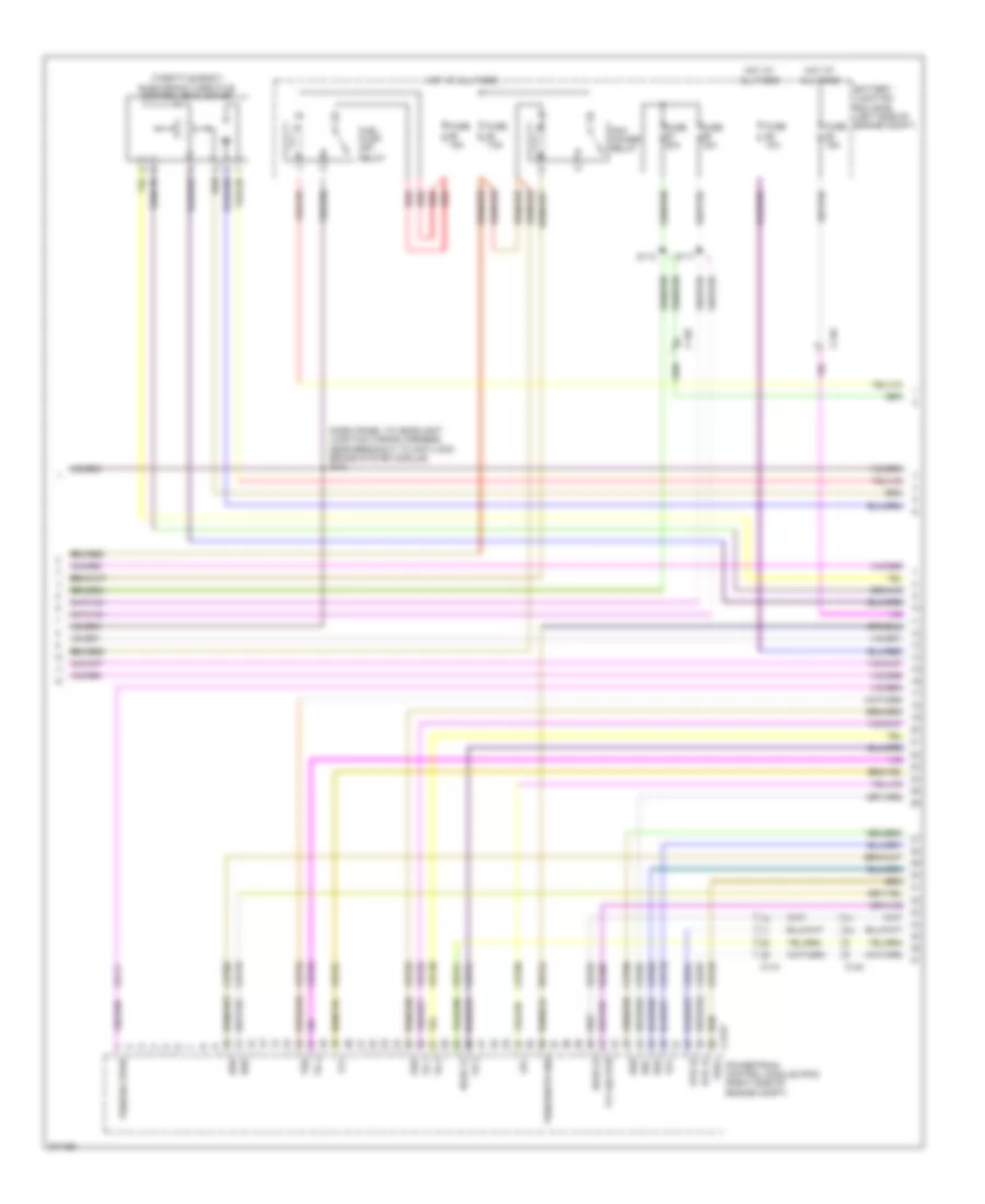 https://portal-diagnostov.com/license.html
Automotive Electricians Portal FZCO
Automotive Electricians Portal FZCO
https://portal-diagnostov.com/license.html
https://portal-diagnostov.com/license.html
Automotive Electricians Portal FZCO
Automotive Electricians Portal FZCOList of elements for 3.7L, Engine Performance Wiring Diagram (3 of 6) for Ford Edge Limited 2013:
- (dash panel to headlight junction wiring harness, near breakout to anti-lock brake system module) s101
- (throttle body) electronic throttle control (etc) motor
- Battery junction box (bjb) (left side of engine compt)
- C110
- C140
- C175t
- Ce233
- Ce234
- Cet05
- Cet06
- Cet07
- Cet08
- Cet09
- Cet10
- Cet18
- Cet49
- Fuel pump (fp) relay
- Fuse 10a
- Fuse 15a
- Fuse 20a
- Fuse 7.5a
- Ho2s 12
- Ho2s 22
- Hot at all times
- Htr 12
- Htr 22
- Le111
- Lpc
- Oss
- Pcm power relay
- Powertrain control module (pcm) (right side of engine compt)
- Re406
- Red
- Ret24
- S113
- S117
- Ssa
- Ssb
- Ssc
- Ssd
- Sse
- Tcc
- Tft
- Tft sig rtn
- Tr 1
- Tr 2
- Tr 3
- Tr 4
- Tspc
- Tss
- Tss/oss vpwr
- Tss/oss/tr gnd
- Ve731
- Ve733
- Vet26
- Vet27
- Vet29
- Vet30
- Vet31
- Vet32
- Vet33
3.7L, Engine Performance Wiring Diagram (4 of 6) for Ford Edge Limited 2013
 https://portal-diagnostov.com/license.html
Automotive Electricians Portal FZCO
Automotive Electricians Portal FZCO
https://portal-diagnostov.com/license.html
https://portal-diagnostov.com/license.html
Automotive Electricians Portal FZCO
Automotive Electricians Portal FZCOList of elements for 3.7L, Engine Performance Wiring Diagram (4 of 6) for Ford Edge Limited 2013:
- (dash panel to headlight junction wiring harness, near breakout to c134) s111
- (dash panel to headlight junction wiring harness, near breakout to c215) s235
- (front of right cylinder bank) cylinder head temperature sensor
- (left side of dash) (w/o intelligent access)
- 6f transmission (on transaxle)
- Body control module (bcm) (left kick panel)
- Brake pedal position (bpp) switch (brake pedal support bracket)
- C192
- C215
- C2280b
- C2280f
- Cet05
- Cet06
- Cet07
- Cet08
- Cet09
- Cet10
- Cet18
- Cet49
- Computer data lines system
- Fuel pump (fet)
- Fuse 10a
- Fuse 5a
- G105 (left front of engine compt)
- Heated oxygen sensor (ho2s) 12 (right front of engine, on exhaust)
- Heated oxygen sensor (ho2s) 22 (left rear of engine, on exhaust)
- Hot at all times
- Hs can +
- Hs can -
- Le111
- Lpc
- Micro
- Nca
- Not used
- Oss
- Passive anti-theft transceiver
- Pcm wake up (fet)
- Re406
- Ret24
- S127 (engine control sensor & fuel charge wiring harness, near breakout to coil on plug 3)
- Ssa
- Ssb
- Ssc
- Ssd
- Sse
- Tcc
- Tft
- Tft sig rtn
- Tr 1
- Tr 2
- Tr 3
- Tr 4
- Tr gnd
- Tspc
- Tss
- Tss/oss gnd
- Tss/oss vpwr
- Universal heated oxygen sensor (ho2s) 11 (right rear of engine, on exhaust)
- Universal heated oxygen sensor (ho2s) 21 (left side of engine, on exhaust)
- Vdb04
- Vdb05
- Vet26
- Vet27
- Vet29
- Vet30
- Vet31
- Vet32
- Vet33
3.7L, Engine Performance Wiring Diagram (5 of 6) for Ford Edge Limited 2013
 https://portal-diagnostov.com/license.html
Automotive Electricians Portal FZCO
Automotive Electricians Portal FZCO
https://portal-diagnostov.com/license.html
https://portal-diagnostov.com/license.html
Automotive Electricians Portal FZCO
Automotive Electricians Portal FZCOList of elements for 3.7L, Engine Performance Wiring Diagram (5 of 6) for Ford Edge Limited 2013:
- (engine control sensor & fuel charge wiring harness, near breakout to powertrain control module)
- (rear of engine) knock sensor
- (rear of left cylinder bank) variable camshaft timing (vct) valve 21
- (rear of left cylinder bank) variable camshaft timing (vct) valve 22
- (rear of right cylinder bank) variable camshaft timing (vct) valve 11
- (rear of right cylinder bank) variable camshaft timing (vct) valve 12
- (right rear of engine) evap canister purge valve
- (top left of engine)
- (top right of engine)
- C140
- Coil on plug (cop) 1
- Coil on plug (cop) 2
- Coil on plug (cop) 3
- Coil on plug (cop) 4
- Coil on plug (cop) 5
- Coil on plug (cop) 6
- Fuel injector
- Fuel injector (top left of engine)
- Fuel injector (top right of engine)
- S124
- S126
- S128 (engine control sensor & fuel charge wiring harness, near breakout to fuel injector 3)
- S131 (engine control sensor & fuel charge wiring harness, near breakout to fuel injector 3)
- Tan
3.7L, Engine Performance Wiring Diagram (6 of 6) for Ford Edge Limited 2013
 https://portal-diagnostov.com/license.html
Automotive Electricians Portal FZCO
Automotive Electricians Portal FZCO
https://portal-diagnostov.com/license.html
https://portal-diagnostov.com/license.html
Automotive Electricians Portal FZCO
Automotive Electricians Portal FZCOList of elements for 3.7L, Engine Performance Wiring Diagram (6 of 6) for Ford Edge Limited 2013:
- (engine control sensor & fuel charge wiring harness, near breakout to crankshaft position sensor)
- (engine control sensor & fuel charge wiring harness, near breakout to powertrain control module)
- (lower left rear of engine) crankshaft position sensor
- (rear of left cylinder bank) camshaft position sensor 21
- (rear of left cylinder bank) camshaft position sensor 22
- (rear of right cylinder bank) camshaft position sensor 11
- (rear of right cylinder bank) camshaft position sensor 12
- Aat
- C175e
- Ce113
- Ce205
- Ce206
- Ce207
- Ce208
- Ce209
- Ce210
- Ce235
- Ce236
- Ce303
- Ce304
- Ce305
- Ce306
- Ce307
- Ce308
- Ce412
- Ce421
- Ce422
- Ce426
- Ce442
- Ce443
- Cht
- Ckp+
- Ckp-
- Cmc24
- Cmp11
- Cmp12
- Cmp21
- Cmp22
- Cop1a
- Cop2c
- Cop3e
- Cop4b
- Cop5d
- Cop6f
- De135
- Etcref
- Etcrtn
- Evapcp
- Inj 1
- Inj 2
- Inj 3
- Inj 4
- Inj 5
- Inj 6
- Instrument cluster system
- Ks1+
- Ks1-
- Ks2+
- Ks2-
- Le134
- Le448
- Le449
- Le450
- Le451
- Le452
- Le453
- Nca
- Oil press
- Powertrain control module (pcm) (right side of engine compt)
- Re134
- Re135
- Re323
- Re324
- Re405
- Re429
- S125
- S130
- S135
- Shdrtn
- Sigrtn
- Tacm+
- Tacm-
- Tp1
- Tp2
- Uo2s11
- Uo2s21
- Uo2sgref11
- Uo2sgref21
- Uo2shtr11
- Uo2shtr21
- Uo2spc11
- Uo2spc21
- Uo2spct11
- Uo2spct21
- Vct11
- Vct12
- Vct21
- Vct22
- Ve706
- Ve707
- Ve711
- Ve712
- Ve740
- Ve801
- Ve802
- Ve818
- Ve819
- Ve826
- Ve827
- Vrsrtn
- Vrsrtn2
EXTERIOR LIGHTS
Backup Lamps Wiring Diagram for Ford Edge Limited 2013
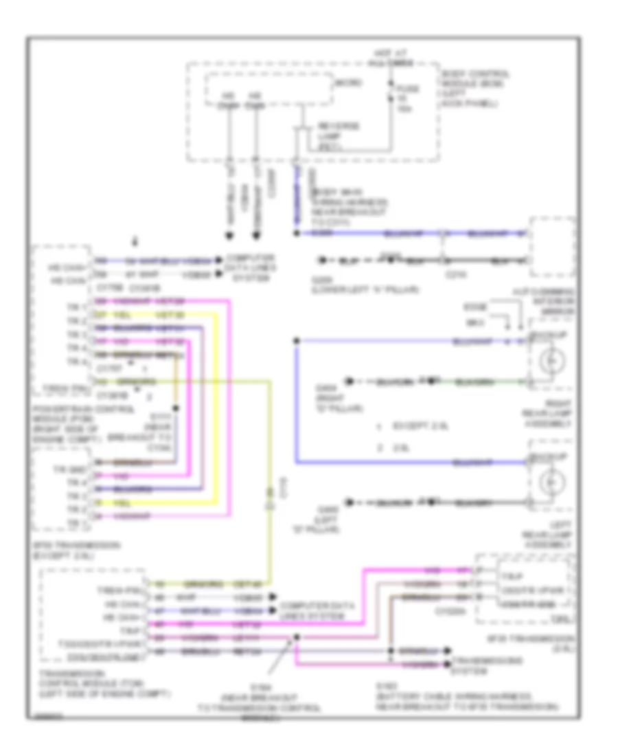 https://portal-diagnostov.com/license.html
Automotive Electricians Portal FZCO
Automotive Electricians Portal FZCO
https://portal-diagnostov.com/license.html
https://portal-diagnostov.com/license.html
Automotive Electricians Portal FZCO
Automotive Electricians Portal FZCOList of elements for Backup Lamps Wiring Diagram for Ford Edge Limited 2013:
- (body main wiring harness, near breakout to c311) s309
- 2.0l
- 6f35 transmission (2.0l)
- 6f50 transmission (except 2.0l)
- Auto-dimming interior mirror
- Backup
- Body control module (bcm) (left kick panel)
- C110
- C1381b
- C1520a
- C175b
- C175t
- C210
- C2280d
- C2280f
- Cet40
- Computer data
- Computer data lines system
- Edge
- Except 2.0l
- Fuse 15a
- G200 (lower left "a" pillar)
- G400 (left "d" pillar)
- G404 (right "d" pillar)
- Hot at all times
- Hs can+
- Hs can-
- Le111
- Left rear lamp assembly
- Lines system
- Micro
- Mkx
- Oss/tr gnd
- Oss/tr vpwr
- Powertrain control module (pcm) (right side of engine compt)
- Ret24
- Reverse lamp (fet)
- Right rear lamp assembly
- S111 (near breakout to c134)
- S183 (battery cable wiring harness, near breakout to 6f35 transmission)
- S184 (near breakout to transmission control module)
- S200
- System
- Tr 1
- Tr 2
- Tr 3
- Tr 4
- Tr gnd
- Tr-p
- Transmission control module (tcm) (left side of engine compt)
- Transmissions
- Trs
- Trsw pin
- Trsw-pin
- Tss/oss/tr gnd
- Tss/oss/tr vpwr
- Vdb04
- Vdb05
- Vet29
- Vet30
- Vet31
- Vet32
Exterior Lamps Wiring Diagram (1 of 2) for Ford Edge Limited 2013
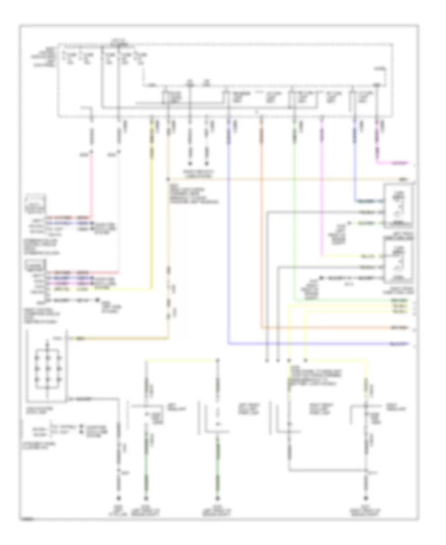 https://portal-diagnostov.com/license.html
Automotive Electricians Portal FZCO
Automotive Electricians Portal FZCO
https://portal-diagnostov.com/license.html
https://portal-diagnostov.com/license.html
Automotive Electricians Portal FZCO
Automotive Electricians Portal FZCOList of elements for Exterior Lamps Wiring Diagram (1 of 2) for Ford Edge Limited 2013:
- Body control module (bcm) (left kick panel)
- Bpp
- C1021a
- C1041a
- C2280a
- C2280b
- C2280c
- C2280d
- C2280f
- C2414a
- C913
- C919
- Ccb08
- Cls32
- Computer data lines system
- Front control interface module (fcim) (center of dash)
- Fuse 15a
- Fuse 20a
- G105 (left front of engine compt)
- G107 (right front of engine compt)
- G205 (left side of dash)
- G400 (left "d" pillar)
- Gd115
- Gnd
- Haz
- Haz sw
- Hazard switch
- High mounted stop lamp
- Hot at all times
- Hs can +
- Hs can -
- Hs can+
- Hs can-
- Ican+
- Ican-
- Intrument panel cluster (ipc)
- Left front auxiliary park lamp
- Left front park/turn lamp
- Left headlamp
- Lf turn lamp (fet)
- Lr turn lamp (fet)
- Micro
- Multi- function switch
- Park
- Reverse lamp (fet)
- Rf turn lamp (fet)
- Right front auxiliary park lamp
- Right front park/turn lamp
- Right headlamp
- Rr turn lamp (fet)
- S109 (dash panel to headlight junction wiring harness, near breakout to battery junction box)
- S114
- S222
- S229
- S307 (body main wiring harness, near breakout to evap canister vent solenoid)
- S401
- Sbp23
- Sbp29
- Side mkr leds
- Steering column control module (sccm) (steering column)
- Stop/ chmsl (fet)
- Turn signal
- Vbatt
- Vdb04
- Vdb05
- Vdb13
- Vdb14
Exterior Lamps Wiring Diagram (2 of 2) for Ford Edge Limited 2013
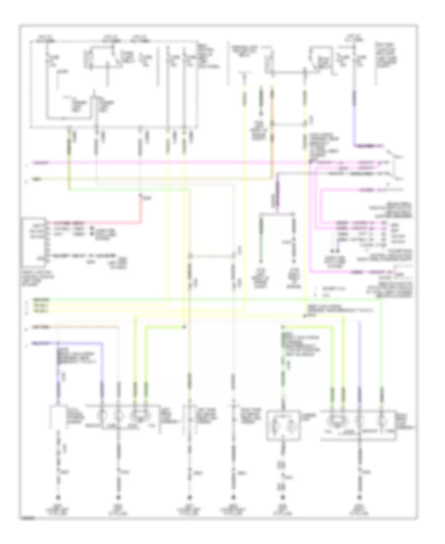 https://portal-diagnostov.com/license.html
Automotive Electricians Portal FZCO
Automotive Electricians Portal FZCO
https://portal-diagnostov.com/license.html
https://portal-diagnostov.com/license.html
Automotive Electricians Portal FZCO
Automotive Electricians Portal FZCOList of elements for Exterior Lamps Wiring Diagram (2 of 2) for Ford Edge Limited 2013:
- (body main wiring harness, near breakout to c311) s342
- (left side of engine compt)
- (main wiring harness, near breakout to g205) (w/ intelligent access) s267
- 2.0l
- Auto- dimming interior mirror
- Backup
- Battery junction box (bjb)
- Body control module (bcm) (left kick panel)
- Bpp
- Bps
- Brake pedal position (bpp) switch (brake pedal support bracket)
- C1381b
- C175b
- C210
- C212
- C215
- C2153c
- C2280a
- C2280d
- C2280e
- C2280f
- C510
- C610
- C919
- Ccb08
- Ces09
- Computer data lines system
- Except 2.0l
- Front lighting control module (left side of dash)
- Fuse 10a
- Fuse 15a
- G105 (left front of engine compt)
- G109 (right front of engine)
- G200 (lower left "a" pillar)
- G201 (lower left "a" pillar)
- G202 (lower right "a" pillar)
- G205 (left side of dash)
- G400 (left "d" pillar)
- G404 (right "d" pillar)
- Gd115
- Gnd
- Hot at all times
- Hs can -
- Hs can+
- Hs can-
- Left rear lamp assembly
- Left side exterior rear view mirror
- Lh corner lamp (fet)
- License lamp
- Micro
- Nca
- Park lamp relay
- Parking lamp trailer tow relay
- Powertrain control module (pcm) (right side of engine compt)
- Remote function actuator (rfa) module (w/ intelligent access) (behind glove box)
- Rh corner lamp (fet)
- Right rear lamp assembly
- Right side exterior rear view mirror
- S200
- S208
- S229
- S309 (body main wiring harness, near breakout to c311)
- S401
- S402
- S408
- S502
- S604
- Sbp23
- Stop
- Stop lamp relay
- Tail
- Turn
- Vbatt
- Vdb04
- Vdb05
- Vent solenoid)
Trailer Adapter Wiring Diagram for Ford Edge Limited 2013
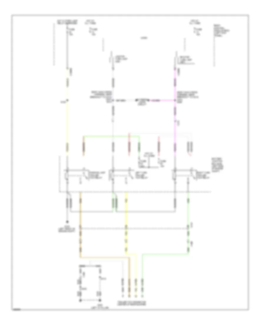 https://portal-diagnostov.com/license.html
Automotive Electricians Portal FZCO
Automotive Electricians Portal FZCO
https://portal-diagnostov.com/license.html
https://portal-diagnostov.com/license.html
Automotive Electricians Portal FZCO
Automotive Electricians Portal FZCOList of elements for Trailer Adapter Wiring Diagram for Ford Edge Limited 2013:
- (body main wiring harness, near breakout to c212) (mkx) s212
- (body main wiring harness, near breakout to c212) (mkx) s255
- Battery junction box (bjb) (left side of engine compt)
- Body control module (bcm) (left kick panel)
- C212
- C2280d
- C2280e
- C406
- Cat06
- Cat09
- Cat17
- Edge
- Exterior lamps circuit
- Fuse 15a
- Fuse 20a
- G105 (left front of engine compt)
- G400 (left "d" pillar)
- Hot at all times
- Hot w/ park lamp relay energized
- Left turn trailer tow relay
- Lr stop/ turn lamp (fet)
- Micro
- Mkx
- Parking lamp trailer tow relay
- Rat08
- Right turn trailer tow relay
- Rr stop/ turn lamp (fet)
- S109
- S402
- S412
- Trailer tow connector (center of rear bumper)
GROUND DISTRIBUTION
Ground Distribution Wiring Diagram (1 of 4) for Ford Edge Limited 2013
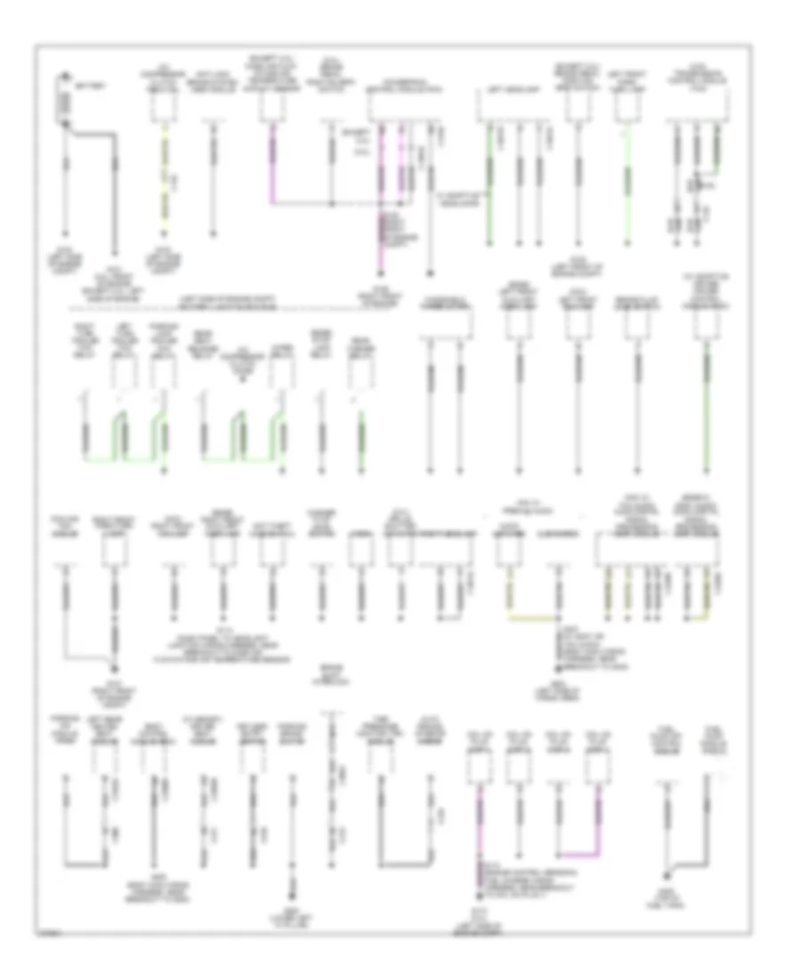 https://portal-diagnostov.com/license.html
Automotive Electricians Portal FZCO
Automotive Electricians Portal FZCO
https://portal-diagnostov.com/license.html
https://portal-diagnostov.com/license.html
Automotive Electricians Portal FZCO
Automotive Electricians Portal FZCOList of elements for Ground Distribution Wiring Diagram (1 of 4) for Ford Edge Limited 2013:
- (2.02) transmission control module (tcm)
- (2.0l)
- (2.0l) brake pedal position (bpp) switch
- (2.0l) grille shutter actuator
- (dash panel to headlight junction wiring harness, near breakout to mass air flow/intake air temperature sensor)
- (edge w/ sony audio) audio digital signal processing (dsp) module
- (edge) left front auxiliary park lamp
- (edge) right front auxiliary park lamp
- (edge) stop lamp relay
- (except 2.0l)
- (except 2.0l) brake pedal position (bpp) switch
- (except 2.0l) mass air flow/ intake air temperature (maf/iat) sensor
- (left side of engine compt) battery junction box (bjb)
- (mkx w/ thx audio) audio digital signal processing (dsp) module
- (mkx) left front fog lamp
- (mkx) right front fog lamp
- (w/ adaptive cruise) cruise- control module (c-cm)
- (w/ memory) driver seat module
- A/c compressor clutch diode
- A/c compressor clutch field coil
- Anti-lock brake system (abs) module
- Anti-theft hood switch
- Audio amplifier
- Auto dimming interior mirror
- Battery
- Body control module (bcm)
- Brake fluid level switch
- Brake shift interlock
- C1021a
- C1021b
- C1041a
- C110
- C11o
- C1381b
- C175b
- C210
- C213
- C2280d
- C300
- C3053
- C311
- C3162a
- C3299b
- C4326c
- C4348c
- C510
- Coil on plug (cop) 1
- Coil on plug (cop) 2
- Coil on plug (cop) 3
- Coil on plug (cop) 4
- Cooling fan module
- Fuel pump (fp) control module
- Fuel pump module shield
- G100 (left side of engine compt)
- G101 (2.0l: front of engine (except 2.0l: left side of engine)
- G103 (left side of engine compt)
- G105 (left front of engine compt)
- G107 (right front of engine compt)
- G109 (right front of engine)
- G110 (2.0l) (left side of engine compt)
- G200 (lower left "a" pillar)
- G403 (left side of cargo area)
- G405 (top of fuel tank)
- Horn
- Keyless entry keypad
- Left front park/ turn lamp
- Left headlamp
- Left rear heated seat module
- Left turn trailer tow relay
- Mkx w/ premium audio
- Nca
- Parking aid module (pam)
- Parking brake switch
- Parking lamp trailer tow relay
- Powertrain control module (pcm)
- Rear seat release relay
- Rear washer relay
- Right front park/turn lamp
- Right headlamp
- Right turn trailer tow relay
- S114
- S200 (body main wiring harness, near breakout to g200)
- S407 (w/ sony or tnx audio) (body main wiring harness, near breakout to g403)
- Subwoofer
- Tire pressure monitor (tpm) module
- W/ adaptive headlamps
- Washer fluid level switch
- Windshield wiper motor
- Wiper relay
Ground Distribution Wiring Diagram (2 of 4) for Ford Edge Limited 2013
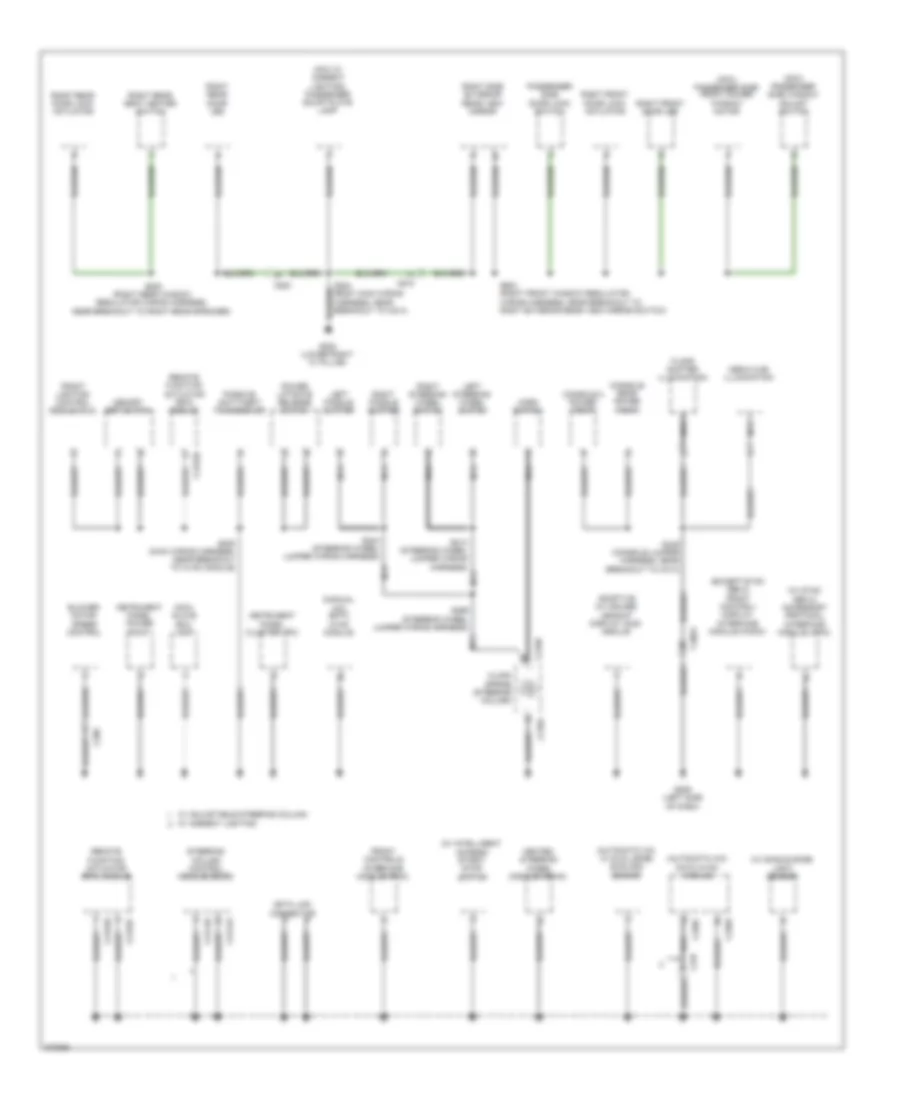 https://portal-diagnostov.com/license.html
Automotive Electricians Portal FZCO
Automotive Electricians Portal FZCO
https://portal-diagnostov.com/license.html
https://portal-diagnostov.com/license.html
Automotive Electricians Portal FZCO
Automotive Electricians Portal FZCOList of elements for Ground Distribution Wiring Diagram (2 of 4) for Ford Edge Limited 2013:
- (automatic a/c w/ dual zone) sunload sensor
- (automatic a/c) datc hvac module
- (except sync gen 2) front control/ display interface module (fcdim)
- (manual a/c) emtc hvac module
- (mkx w/ ambient lighting) passenger scuff plate lamp
- (mkx) glove box lamp
- (mkx) passenger side front power window motor
- (mkx) passenger side window adjust switch
- (w/ intelligent access) start/ stop switch
- (w/ single zone) light sensor
- (w/ sync gen 2) accessory protocol interface module (apim)
- Adaptive (w/ cruise) headup display (hud) module
- Blower motor speed control
- C2153c
- C2153d
- C2153e
- C218a
- C218b
- C228a
- C228c
- C237
- C2414a
- C2414b
- C260
- C3053
- C610
- C800
- Clock spring (steering column)
- Console 2 power point
- Console rear power point
- Data link connector
- Floor shifter illumination
- Front controls interface module (fcim)
- Front lighting control module (flm)
- G202 (lower right "a" pillar)
- G205 (left side of dash)
- Heated steering wheel module (hswm)
- Horn switch
- Instrument panel cluster (ipc)
- Instrument panel power point
- Left paddle shifter
- Left steering wheel switch
- Media hub illumination
- Memory set switch
- Nca
- Passenger side door lock switch
- Passive anti-theft transceiver
- Power liftgate release switch
- Remote function actuator (rfa) module
- Right front door led
- Right front door lock actuator
- Right paddle shifter
- Right rear door led
- Right rear door lock actuator
- Right rear seat heater switch
- Right side exterior rear view mirror
- Right steering wheel switch
- S204 (body main wiring harness, near breakout to c214)
- S208 (main wiring harness, near breakout to hvac module)
- S213 (steering wheel jumper wiring harness) nca
- S244 (steering wheel jumper wiring harness)
- S299 (steering wheel jumper wiring harness)
- S349 (console jumper harness, near breakout to c313)
- S604 (right front window regulator wiring harness, near breakout to right exterior rear view mirror switch)
- S800 (right rear window regulator wiring harness, near breakout to right rear speaker)
- Steering column control module (sccm)
- W/ adjustable steering column w/ ambient lighting
Ground Distribution Wiring Diagram (3 of 4) for Ford Edge Limited 2013
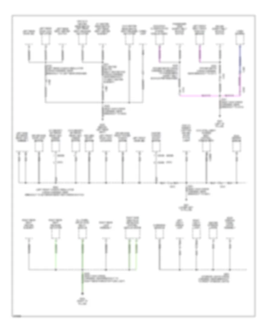 https://portal-diagnostov.com/license.html
Automotive Electricians Portal FZCO
Automotive Electricians Portal FZCO
https://portal-diagnostov.com/license.html
https://portal-diagnostov.com/license.html
Automotive Electricians Portal FZCO
Automotive Electricians Portal FZCOList of elements for Ground Distribution Wiring Diagram (3 of 4) for Ford Edge Limited 2013:
- (edge)
- (max w/ ambient lighting) driver scuff plate lamp
- (mkx & w/ heated rear seats) left rear seat release actuator
- (mkx)
- (w/ heated rear seats) left rear seat heater element
- (w/ memory) exterior rear view mirror switch
- (w/o heated rear seats) seat release actuator
- (w/o intelligent access) body control module (bcm)
- (w/o memory) exterior rear view mirror switch
- All wheel drive (awd) relay module
- C210
- C2280d
- C300
- C312
- C314
- C495
- C504b
- C510
- C535b
- C700
- C919
- Cargo lamp
- Center interior lamps
- Driver safety belt buckle switch
- Driver side door lock switch
- Driver side front power window motor
- G201 (lower left "a" pillar)
- G300 (behind left rear seat)
- G301 (left "b" pillar)
- G404 (right "d" pillar)
- Keyless entry keypad
- Left front door led
- Left front door lock actuator
- Left front seat track position sensor
- Left rear door led
- Left rear door lock actuator
- Left rear seat heater switch
- Left side exterior rear view mirror
- Left vanity mirror lamp
- Master window adjust switch
- Nca
- Occupant classification system module (ocsm)
- Overhead console
- Passenger side safety belt buckle switch
- Rain sensor module
- Right rear lamp assembly
- Right rear seat heater element
- Right rear seat release actuator
- Right side obstacle detection control module (sod-r)
- Right vanity mirror lamp
- Roof opening panel motor assembly
- S201 (body main wiring harness, near breakout to g201)
- S301 (w/ heated seats) (seat heated pad wiring harness, near breakout to seat heater element)
- S306 (body main wiring harness, near breakout to g300)
- S341 (body main wiring harness, near breakout to c312)
- S408 (body main wiring harness, near breakout to right rear park/stop/turn light)
- S502 (left front window regulator wiring harness, near breakout to exterior rear view mirror switch)
- S903 (interior lights wiring harness, near breakout to front interior lights)
- Video camera
Ground Distribution Wiring Diagram (4 of 4) for Ford Edge Limited 2013
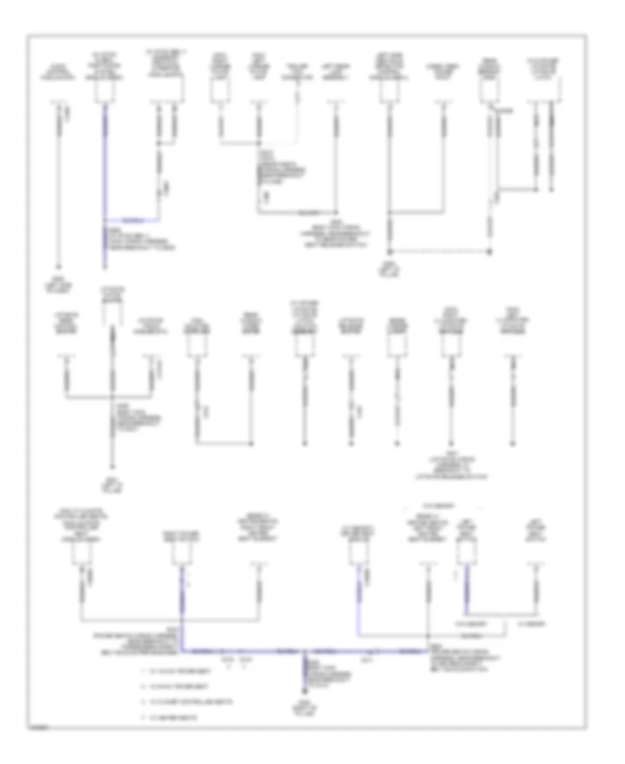 https://portal-diagnostov.com/license.html
Automotive Electricians Portal FZCO
Automotive Electricians Portal FZCO
https://portal-diagnostov.com/license.html
https://portal-diagnostov.com/license.html
Automotive Electricians Portal FZCO
Automotive Electricians Portal FZCOList of elements for Ground Distribution Wiring Diagram (4 of 4) for Ford Edge Limited 2013:
- (edge w/ heated seats) left front heated seat element
- (edge w/ heated seats) right front heated seat element
- (edge) license lamp
- (mkx w/ climate controlled seats) dual climate controlled seat module (dcsm)
- (mkx) left license plate lamp
- (mkx) right license plate lamp
- (w/ memory) driver seat module
- (w/ power liftgate) liftgate latch/ unlatch assembly
- (w/ sync gen 1) (main wiring harness, near breakout to g205)
- (w/ sync gen 1) acessory protocol interface module(apim)
- (w/ sync) global positioning system module (gpsm)
- (w/o power liftgate) liftgate latch
- Audio control module (acm)
- C240a
- C3036a
- C3053
- C311
- C315
- C316
- C3299a
- C402b
- C406
- C4174a
- C432
- C913
- C925
- Cargo area power point
- G206 (left side of dash)
- G302 (right "b" pillar)
- G400 (left "d" pillar)
- G401 (left "d" pillar)
- High mounted stoplamp
- Left power seat switch
- Left rear lamp assembly
- Left side obstacle detection control module (sod-l)
- Liftgate motor clutch
- Liftgate rear control switch
- Liftgate release switch
- Liftgate/ trunk module (ltm)
- Nca
- Near breakout to g401)
- Rear window defrost grid
- Rear window wiper motor
- Right power seat switch
- S320 (power seats wiring harness, near breakout to driver's safety belt buckle switch)
- S330 (power seats wiring harness, near breakout to passenger's safety belt buckle pretensioner)
- S401 (liftgate wiring harness, in breakout to liftgate release switch)
- S402 (body main wiring harness, near breakout to rear power seat release switch)
- Trailer tow connector
- W/ 10-way power seat
- W/ 6-way power seat
- W/ climaet controlled seats
- W/ heated seats
- W/ memory
- W/o memory
HEADLIGHTS
Adaptive Front Lighting Wiring Diagram for Ford Edge Limited 2013
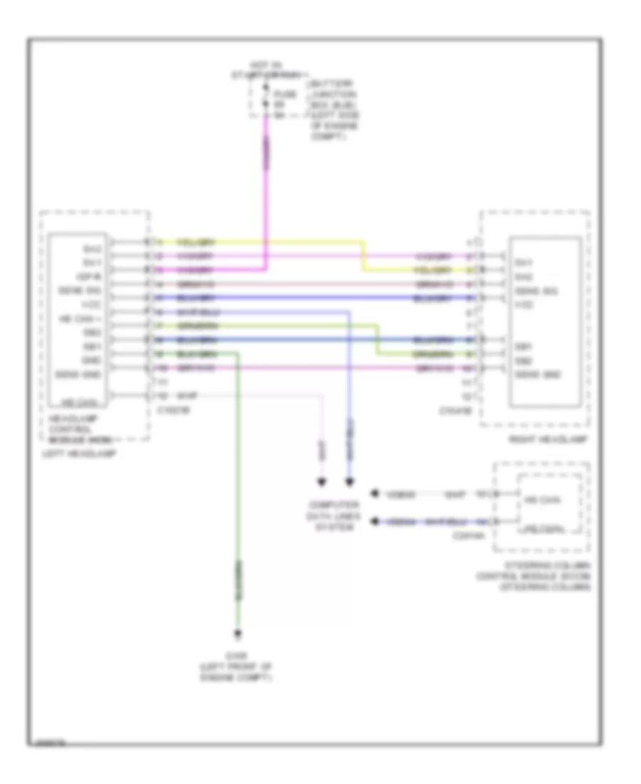 https://portal-diagnostov.com/license.html
Automotive Electricians Portal FZCO
Automotive Electricians Portal FZCO
https://portal-diagnostov.com/license.html
https://portal-diagnostov.com/license.html
Automotive Electricians Portal FZCO
Automotive Electricians Portal FZCOList of elements for Adaptive Front Lighting Wiring Diagram for Ford Edge Limited 2013:
- Battery junction box (bjb) (left side of engine compt)
- C1021b
- C1041b
- C2414a
- Computer
- Data lines system
- Fuse 5a
- G105 (left front of engine compt)
- Gnd
- Headlamp control module (hcm)
- Hot in start or run
- Hs can +
- Hs can -
- Hs can+
- Hs can-
- Isp-r
- Left headlamp
- Right headlamp
- Sa1
- Sa2
- Sb1
- Sb2
- Sens gnd
- Sens sig
- Steering column control module (sccm) (steering column)
- Vcc
- Vdb04
- Vdb05
Headlamps Wiring Diagram, with High Intensity Gas Discharge Headlights for Ford Edge Limited 2013
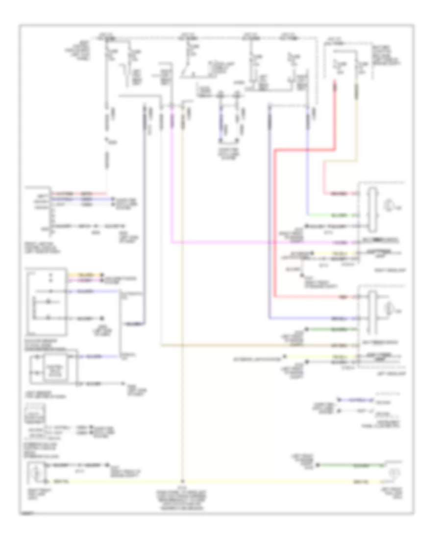 https://portal-diagnostov.com/license.html
Automotive Electricians Portal FZCO
Automotive Electricians Portal FZCO
https://portal-diagnostov.com/license.html
https://portal-diagnostov.com/license.html
Automotive Electricians Portal FZCO
Automotive Electricians Portal FZCOList of elements for Headlamps Wiring Diagram, with High Intensity Gas Discharge Headlights for Ford Edge Limited 2013:
- (left front of engine compt) g105
- Air conditioning system
- Auto- lamps sen in
- Automatic a/c
- Battery junction box (bjb) (left side of engine compt)
- Body control module (bcm) (left kick panel)
- C1021a
- C1041a
- C2280a
- C2280b
- C2280e
- C2280f
- C2414a
- Computer data lines system
- Control solid state
- Exterior lights system
- Fog lamp relay (mkx)
- Front lighting control module (left side of dash)
- Fuse 10a
- Fuse 15a
- Fuse 20a
- G105 (left front of engine compt)
- G107 (right front of engine compt)
- G205 (left side of dash)
- Gd115
- Gnd
- Hid
- Hot at all times
- Hs can+
- Hs can-
- Instrument panel cluster (ipc)
- Leds
- Left front fog lamp (mkx)
- Left headlamp
- Left high beam (fet)
- Left low beam (fet)
- Light sensor (top center of dash)
- Manual a/c
- Micro
- Multi- function switch
- Red
- Right front fog lamp (mkx)
- Right headlamp
- Right high beam (fet)
- Right low beam (fet)
- S114
- S115 (dash panel to headlight junction wiring harness, near breakout to mass air flow/intake air temperature sensor)
- S208
- S229
- Sbp23
- Shutter solenoid
- Side marker
- Solid state
- Steering column control module (sccm) (steering column)
- Sunload sensor (w/ dual zone) (top center of dash)
- Vbatt
- Vdb04
- Vdb05
- Vlf14
Headlamps Wiring Diagram, without High Intensity Gas Discharge Headlights for Ford Edge Limited 2013
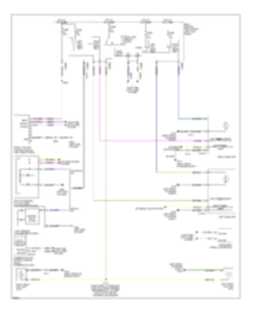 https://portal-diagnostov.com/license.html
Automotive Electricians Portal FZCO
Automotive Electricians Portal FZCO
https://portal-diagnostov.com/license.html
https://portal-diagnostov.com/license.html
Automotive Electricians Portal FZCO
Automotive Electricians Portal FZCOList of elements for Headlamps Wiring Diagram, without High Intensity Gas Discharge Headlights for Ford Edge Limited 2013:
- (left front of engine compt) g105
- Air conditioning system
- Auto- lamps sen in
- Automatic a/c
- Body control module (bcm) (left kick panel)
- C1021a
- C1041a
- C2280a
- C2280b
- C2280e
- C2280f
- C2414a
- Computer data lines system
- Control solid state
- Exterior lights system
- Fog lamp relay (mkx)
- Front lighting control module (left side of dash)
- Fuse 10a
- Fuse 15a
- G105 (left front of engine compt)
- G107 (right front of engine compt)
- G205 (left side of dash)
- Gd115
- Gnd
- Hot at all times
- Hs can+
- Hs can-
- Instrument panel cluster (ipc)
- Leds
- Left front fog lamp (mkx)
- Left headlamp
- Left high beam (fet)
- Left low beam (fet)
- Light sensor (top center of dash)
- Manual a/c
- Micro
- Multi- function switch
- Right front fog lamp (mkx)
- Right headlamp
- Right high beam (fet)
- Right low beam (fet)
- S114
- S115 (dash panel to headlight junction wiring harness, near breakout to mass air flow/intake air temperature sensor)
- S208
- S229
- Sbp23
- Shutter solenoid
- Side marker
- Solid state
- Steering column control module (sccm) (steering column)
- Sunload sensor (w/ dual zone) (top center of dash)
- Vbatt
- Vdb04
- Vdb05
- Vlf14
HORN
Horn Wiring Diagram for Ford Edge Limited 2013
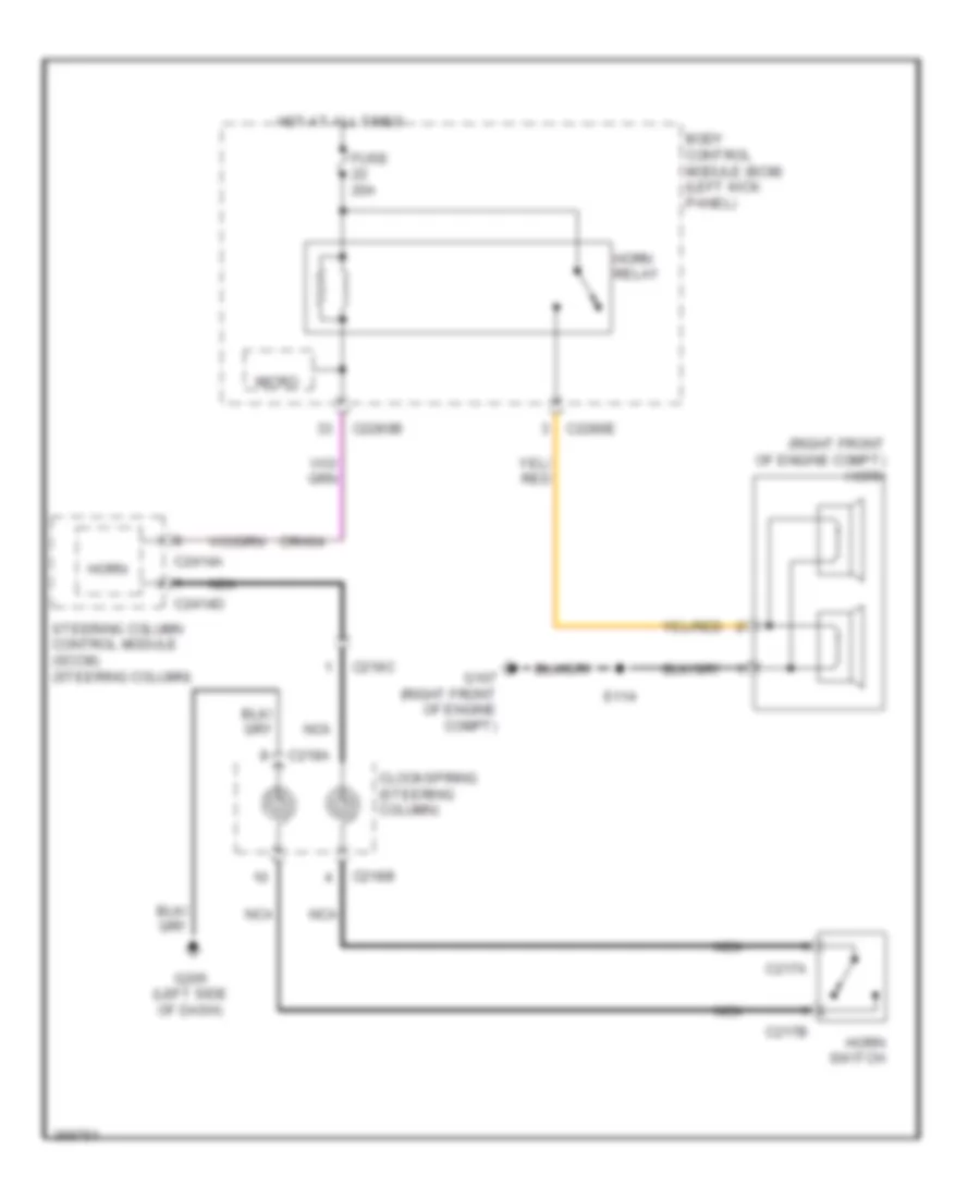 https://portal-diagnostov.com/license.html
Automotive Electricians Portal FZCO
Automotive Electricians Portal FZCO
https://portal-diagnostov.com/license.html
https://portal-diagnostov.com/license.html
Automotive Electricians Portal FZCO
Automotive Electricians Portal FZCOList of elements for Horn Wiring Diagram for Ford Edge Limited 2013:
- (right front of engine compt) horn
- Body control module (bcm) (left kick panel)
- C217a
- C217b
- C218a
- C218b
- C218c
- C2280b
- C2280e
- C2414a
- C2414d
- Clockspring (steering column)
- Crh04
- Fuse 20a
- G107 (right front of engine compt)
- G205 (left side of dash)
- Horn
- Horn relay
- Horn switch
- Hot at all times
- Micro
- Nca
- S114
- Steering column control module (sccm) (steering column)
INSTRUMENT CLUSTER
Instrument Cluster Wiring Diagram (1 of 2) for Ford Edge Limited 2013
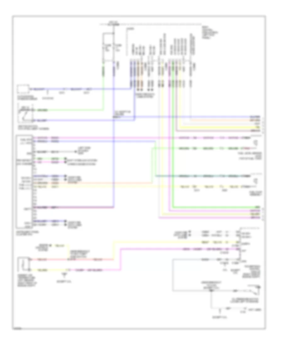 https://portal-diagnostov.com/license.html
Automotive Electricians Portal FZCO
Automotive Electricians Portal FZCO
https://portal-diagnostov.com/license.html
https://portal-diagnostov.com/license.html
Automotive Electricians Portal FZCO
Automotive Electricians Portal FZCOList of elements for Instrument Cluster Wiring Diagram (1 of 2) for Ford Edge Limited 2013:
- (left side of dash) g205
- (near breakout to anti-theft hood switch) s119
- (near breakout to c140) (except 2.0l) s121
- (not used)
- (w/ adaptive cruise) s214
- 2.0l
- Aat
- Ambient air temperature (aat) sensor (right front of engine compt)
- Auto-dimming interior mirror
- Body control module (bcm) (left kick panel)
- Brk fluid sw
- Brk fluid sw rtn
- C1381b
- C1381e
- C140
- C175b
- C175e
- C210
- C213
- C2280a
- C2280b
- C2280c
- C2280f
- C405
- Cdc30
- Cet52
- Cmc19
- Cmc20
- Cmc24
- Cmc25
- Compass
- Computer data lines system
- Cpl26
- Cpl31
- Cpl36
- Cpl39
- Cpl58
- Engine controls system
- Except 2.0l
- Fuel level sensor (4wd) (top of fuel tank)
- Fuel lvl 1
- Fuel lvl 2
- Fuel pump assembly
- Fuel rtn
- Fuse 10a
- Fuse 15a
- Gd115
- Gnd
- Hot at all times
- Hs can +
- Hs can -
- Ican +
- Ican -
- Ignition switch (w/o intelligent access)
- Instrument panel cluster (ipc)
- Key in
- Key in ignition
- Lf door ajar
- Liftgate/decklid glass ajar sw
- Low washer
- Lr door ajar
- Lvl 1 rtn
- Micro
- Ms can +
- Ms can -
- Nca
- Oil pressure switch (lower left of engine)
- Ops
- Pnk
- Powertrain control module (right side of engine compt)
- Prk brk
- Prk detect
- Re407
- Rf door ajar
- Rmc19
- Rmc32
- Rmc33
- Rr door ajar
- Sbp11
- Shift interlock system
- Sigrtn
- Vbatt
- Vdb04
- Vdb05
- Vdb06
- Vdb07
- Vdb13
- Vdb14
- Vdn01
- Ve740
- Vmc11
- Vmc23
- W/o sync
- Wiper/washer system
Instrument Cluster Wiring Diagram (2 of 2) for Ford Edge Limited 2013
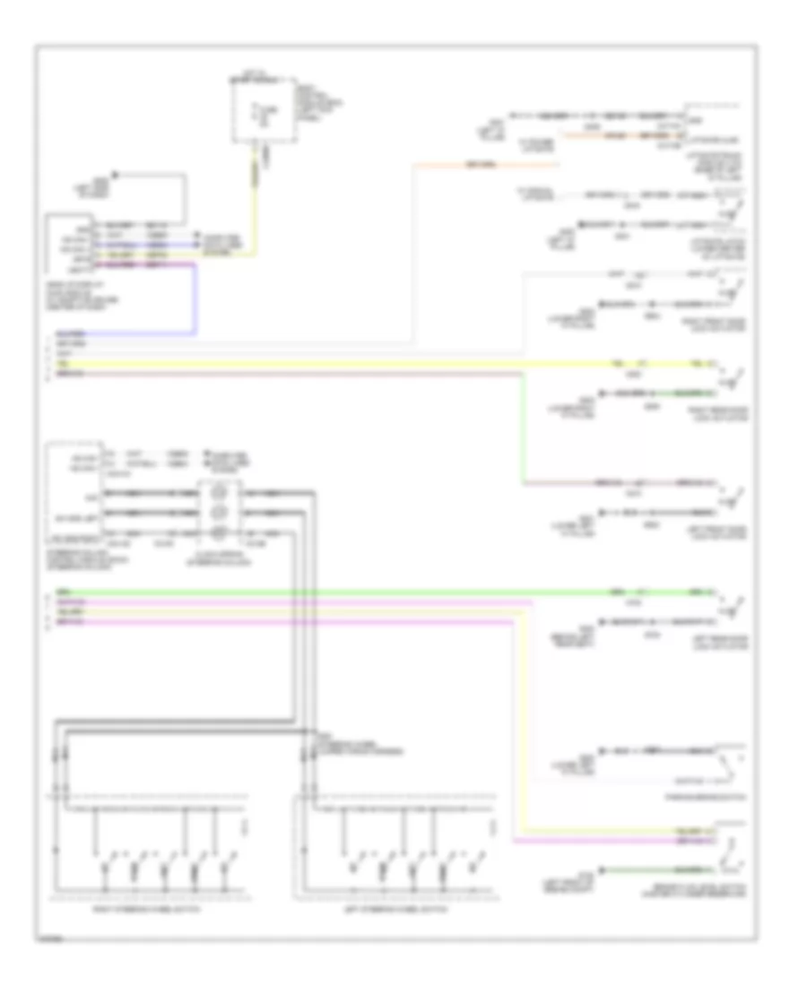 https://portal-diagnostov.com/license.html
Automotive Electricians Portal FZCO
Automotive Electricians Portal FZCO
https://portal-diagnostov.com/license.html
https://portal-diagnostov.com/license.html
Automotive Electricians Portal FZCO
Automotive Electricians Portal FZCOList of elements for Instrument Cluster Wiring Diagram (2 of 2) for Ford Edge Limited 2013:
- A/d1
- Ajar
- Body control module (bcm) (left kick panel)
- Brake fluid level switch (master cylinder reservoir)
- C218b
- C218c
- C2280b
- C2414a
- C2414d
- C4174a
- C4174b
- C510
- C610
- C700
- C800
- C919
- Cbp35
- Clock spring (steering column)
- Computer data lines system
- Cpl58
- Down
- Fuse 5a
- G105 (left front of engine compt)
- G200 (lower left "a" pillar)
- G201 (lower left "a" pillar)
- G202 (lower right "a" pillar)
- G205 (left side of dash)
- G300 (behind left rear seat)
- G400 (left "d" pillar)
- G401 (left "d" pillar)
- Gd115
- Gd149
- Gnd
- Head up display (hud) module (w/ adaptive cruise) (center of dash)
- Hot in start or run
- Hs can +
- Hs can -
- Isp-r
- Left
- Left front door lock actuator
- Left rear door lock actuator
- Left steering wheel switch
- Liftgate ajar
- Liftgate latch (lower center of liftgate)
- Liftgate/trunk module (ltm) (base of left "d" pillar)
- Nca
- Parking brake switch
- Right
- Right front door lock actuator
- Right rear door lock actuator
- Right steering wheel switch
- S200
- S291 (steering wheel jumper wiring harness)
- S401
- S409
- S502
- S604
- S700
- S800
- Sbp11
- Steering column control module (sccm) (steering column)
- Sw gnd left
- Sw gnd right
- Vbatt
- Vdb04
- Vdb05
- W/ manual liftgate
- W/ power liftgate
INTERIOR LIGHTS
Courtesy Lamps Wiring Diagram (1 of 3) for Ford Edge Limited 2013
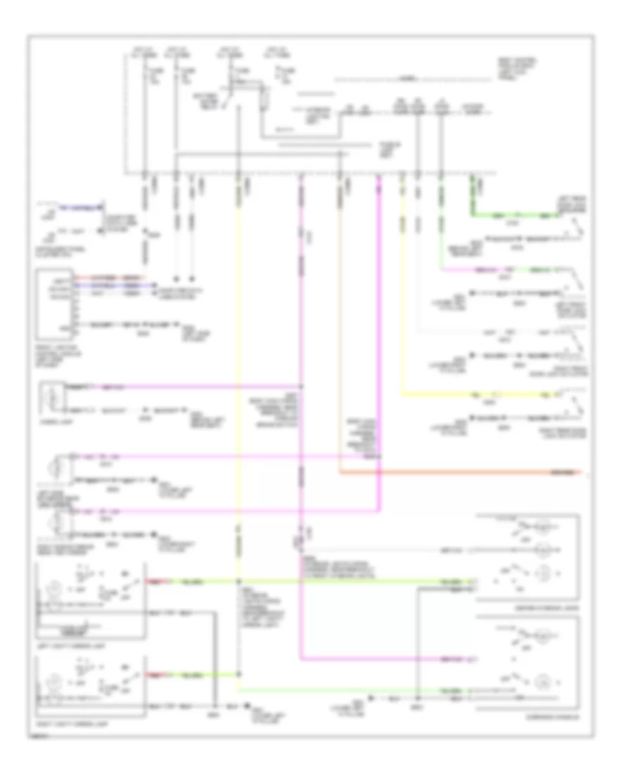 https://portal-diagnostov.com/license.html
Automotive Electricians Portal FZCO
Automotive Electricians Portal FZCO
https://portal-diagnostov.com/license.html
https://portal-diagnostov.com/license.html
Automotive Electricians Portal FZCO
Automotive Electricians Portal FZCOList of elements for Courtesy Lamps Wiring Diagram (1 of 3) for Ford Edge Limited 2013:
- (body main wiring harness, near breakout to c510) s236
- Battery saver relay
- Body control module (bcm) (left kick panel)
- C210
- C213
- C2280a
- C2280c
- C2280d
- C2280f
- C510
- C610
- C700
- C800
- Cargo lamp
- Center interior lamps
- Computer data lines system
- Cpl26
- Cpl31
- Cpl36
- Cpl39
- Front lighting control module (left side of dash)
- Fuse 10a
- Fuse 15a
- Fuse 2a
- G201 (lower left "a" pillar)
- G202 (lower right "a" pillar)
- G205 (left side of dash)
- G300 (behind left rear seat)
- Gd115
- Gnd
- Homelink module
- Hot at all times
- Hs can+
- Hs can-
- Instrument panel cluster (ipc)
- Interior lighting (fet)
- Left front door lock actuator
- Left rear door lock actuator
- Left side exterior rear view mirror
- Left vanity mirror lamp
- Lf door ajar
- Lr door ajar
- Micro
- Nca
- Off
- Overhead console
- Puddle lamp (fet)
- Red
- Rf door ajar
- Right front door lock actuator
- Right rear door lock actuator
- Right side exterior rear view mirror
- Right vanity mirror lamp
- Rr door ajar
- S208
- S229
- S297 (body main wiring harness, near breakout to parking brake switch)
- S306
- S502
- S604
- S700
- S800
- S901 (interior lights wiring harness, near breakout to left vanity mirror light)
- S903
- S906 (interior lights wiring harness, near breakout to front interior lights)
- Sbp23
- Vbatt
- Vdb04
- Vdb05
Courtesy Lamps Wiring Diagram (2 of 3) for Ford Edge Limited 2013
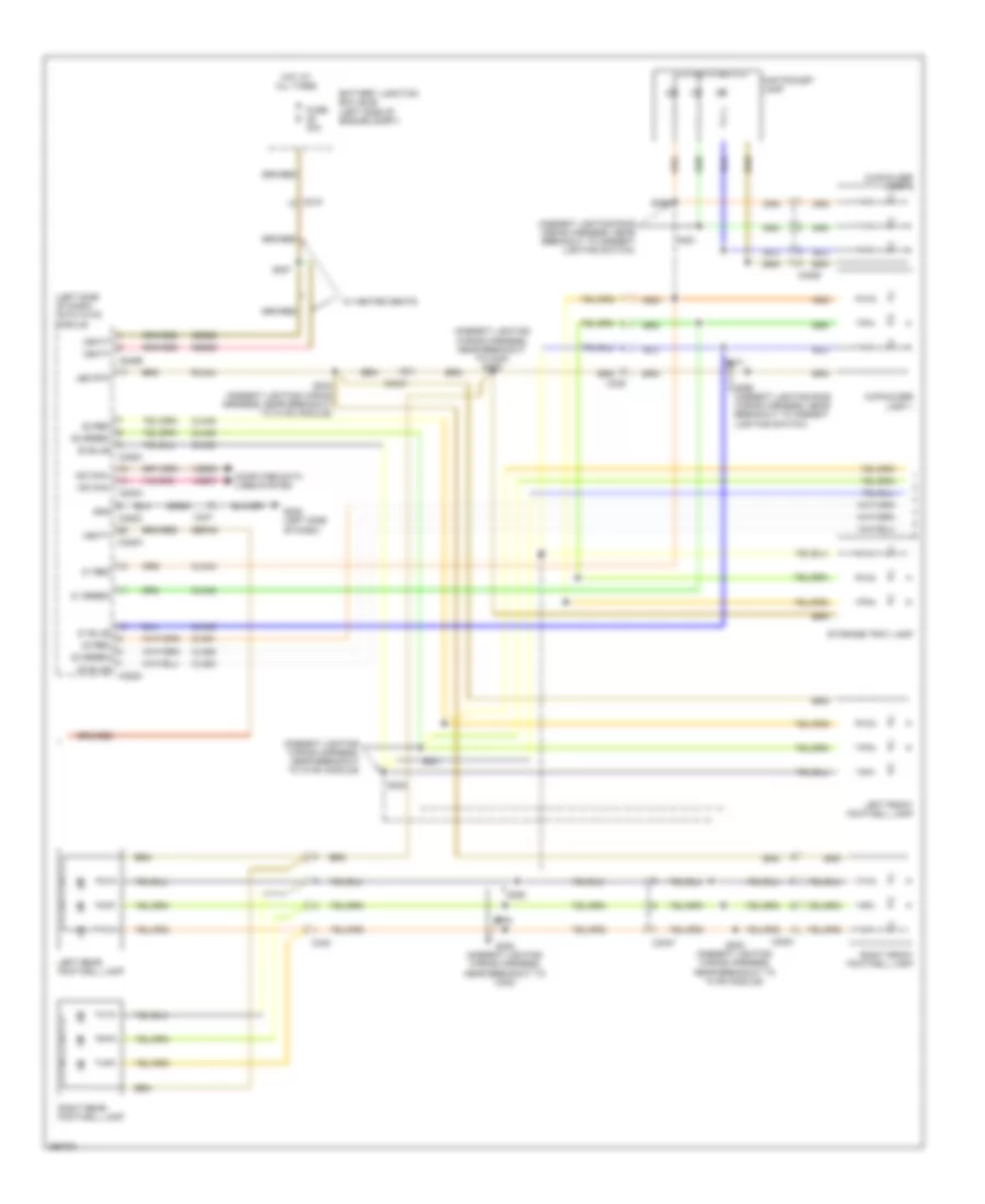 https://portal-diagnostov.com/license.html
Automotive Electricians Portal FZCO
Automotive Electricians Portal FZCO
https://portal-diagnostov.com/license.html
https://portal-diagnostov.com/license.html
Automotive Electricians Portal FZCO
Automotive Electricians Portal FZCOList of elements for Courtesy Lamps Wiring Diagram (2 of 3) for Ford Edge Limited 2013:
- (ambient lighting ring wiring harness, near breakout to ambient lighting switch)
- (ambient lighting wiring harness, near breakout to c340) s376
- (ambient lighting wiring harness, near breakout to hvac module)
- (left side of dash) datc hvac module
- Battery junction box (bjb) (left side of engine compt)
- C215
- C228a
- C228b
- C228c
- C237
- C3047
- C3050
- C3051
- C339
- C340
- Cln44
- Cln45
- Cln46
- Cln48
- Cln49
- Cln50
- Cln51
- Cln52
- Cln53
- Computer data lines system
- Cupholder lamp 1
- Cupholder lamp 2
- Fuse 30a
- G205 (left side of dash)
- Gd908
- Gnd
- Hot at all times
- Led rtn
- Left front footwell lamp
- Left rear footwell lamp
- Map pocket lamp
- Ms can+
- Ms can-
- Right front footwell lamp
- Right rear footwell lamp
- Rln44
- S207
- S223 (ambient lighting wiring harness, near breakout to hvac module)
- S230 (ambient lighting wiring harness, near breakout to hvac module)
- S231
- S232
- S368
- S369 (ambient lighting ring wiring harness, near breakout to ambient lighting switch)
- S371
- S381
- S383 (ambient lighting wiring harness, near breakout to c340)
- S384
- S385
- Sbb28
- Sbp46
- Storage tray lamp
- Vbatt
- Vdb06
- Vdb07
- W/ heated seats
- Z1 green
- Z1 red
- Z2 green
- Z2 red
- Z3 green
- Z3 red
Courtesy Lamps Wiring Diagram (3 of 3) for Ford Edge Limited 2013
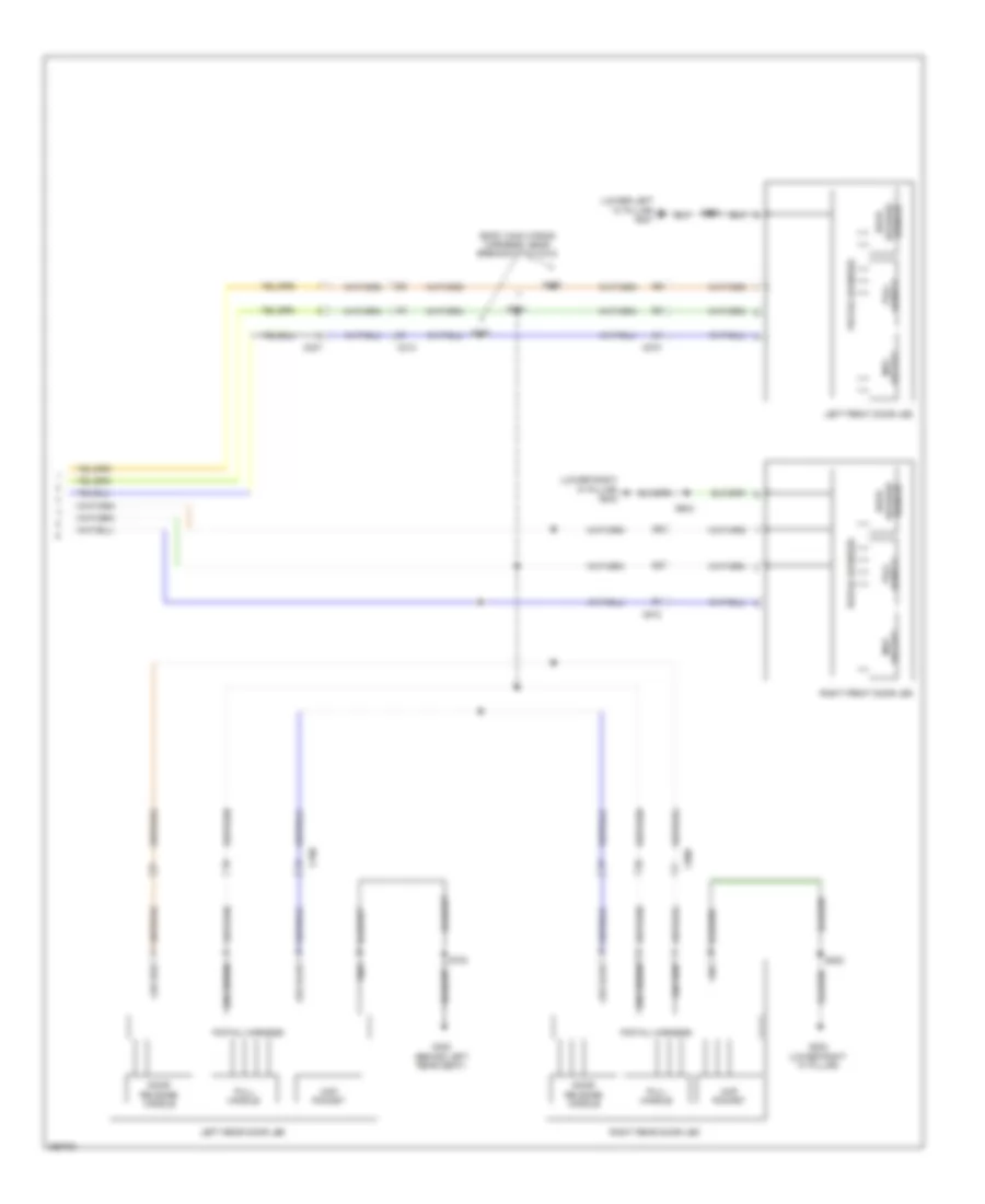 https://portal-diagnostov.com/license.html
Automotive Electricians Portal FZCO
Automotive Electricians Portal FZCO
https://portal-diagnostov.com/license.html
https://portal-diagnostov.com/license.html
Automotive Electricians Portal FZCO
Automotive Electricians Portal FZCOList of elements for Courtesy Lamps Wiring Diagram (3 of 3) for Ford Edge Limited 2013:
- (body main wiring harness, near breakout to c312)
- (lower left "a" pillar) g201
- (lower right "a" pillar) g202
- C213
- C237
- C510
- C610
- C700
- C800
- Door release handle
- G202 (lower right "a" pillar)
- G300 (behind left rear seat)
- Gnd
- Handle pull
- Handle release door
- Led green
- Led red
- Left front door led
- Left rear door led
- Map pocket
- Pigtail harness
- Pocket map
- Pull handle
- Right front door led
- Right rear door led
- S372
- S374
- S375
- S502
- S604
- S700
- S800
Instrument Illumination Wiring Diagram for Ford Edge Limited 2013
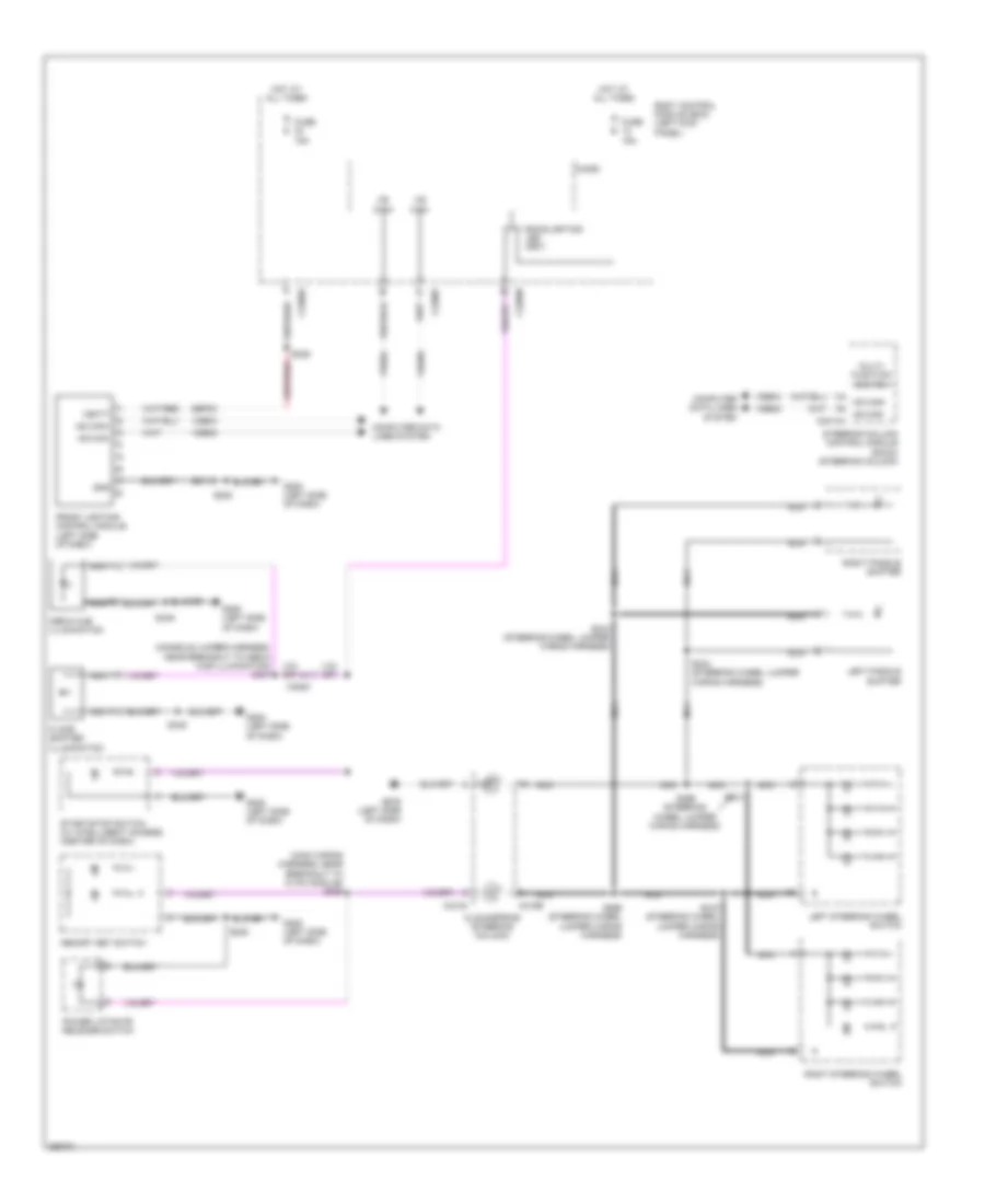 https://portal-diagnostov.com/license.html
Automotive Electricians Portal FZCO
Automotive Electricians Portal FZCO
https://portal-diagnostov.com/license.html
https://portal-diagnostov.com/license.html
Automotive Electricians Portal FZCO
Automotive Electricians Portal FZCOList of elements for Instrument Illumination Wiring Diagram for Ford Edge Limited 2013:
- (console jumper harness, near breakout to media hub illumination) s337
- (main wiring harness, near breakout to hvac module) s209
- Backlighting led (fet)
- Body control module (bcm) (left kick panel)
- C218a
- C218b
- C2280a
- C2280b
- C2280f
- C3053
- Clockspring (steering column)
- Computer data lines system
- Floor shifter illumination
- Front lighting control module (left side of dash)
- Fuse 15a
- G205 (left side of dash)
- Gd115
- Gnd
- Hot at all times
- Hs can+
- Hs can-
- Hs can- c2414a
- Left paddle shifter
- Left steering wheel switch
- Media hub illumination
- Memory set switch
- Micro
- Multi- function switch
- Nca
- Power liftgate release switch
- Right paddle shifter
- Right steering wheel switch
- S208
- S213
- S215 (steering wheel jumper wiring harness)
- S229
- S243 (steering wheel jumper wiring harness)
- S244 (steering wheel jumper wiring harness)
- S266 (steering wheel jumper wiring harness)
- S299 (steering wheel jumper wiring harness)
- S349
- Sbp23
- Start/stop switch (w/ intelligent access) (center of dash)
- Steering column control module (sccm) (steering column)
- Vbatt
- Vdb04
- Vdb05
MEMORY SYSTEMS
Driver"s Memory Seat Wiring Diagram (1 of 2) for Ford Edge Limited 2013
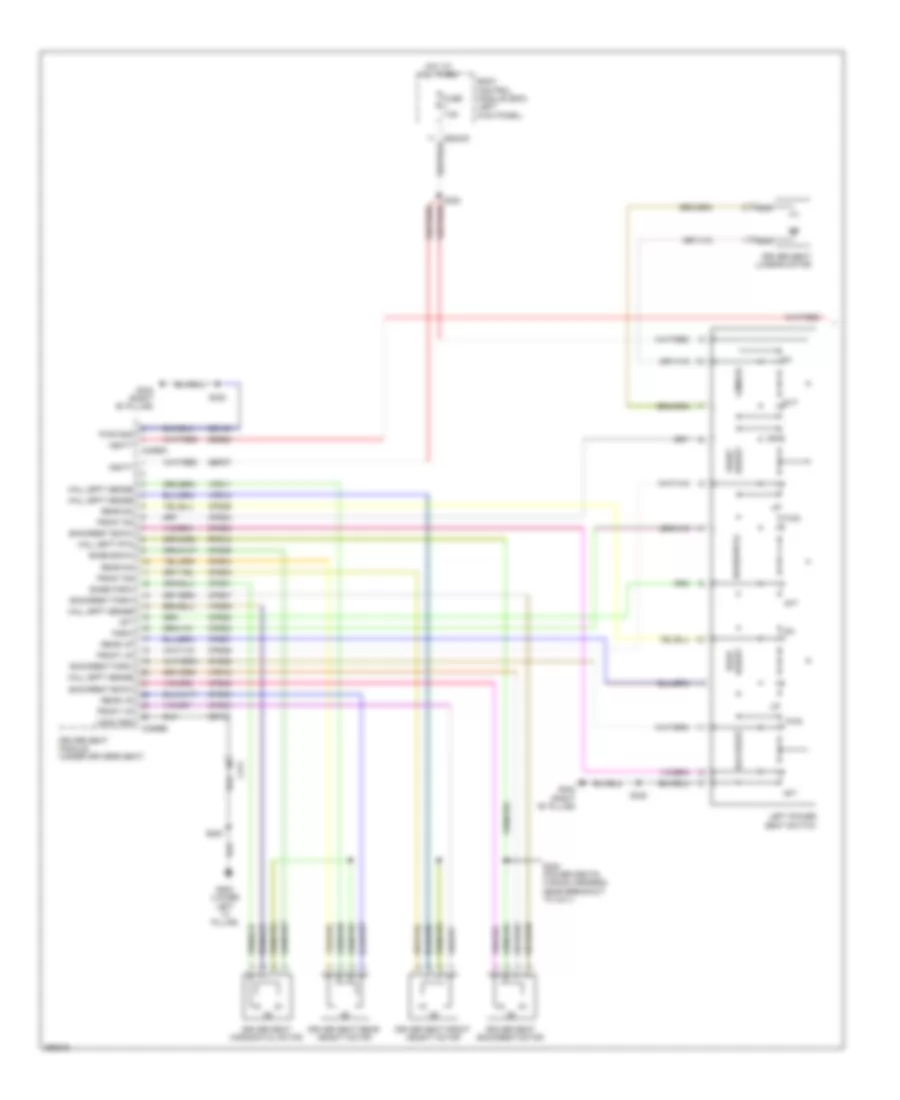 https://portal-diagnostov.com/license.html
Automotive Electricians Portal FZCO
Automotive Electricians Portal FZCO
https://portal-diagnostov.com/license.html
https://portal-diagnostov.com/license.html
Automotive Electricians Portal FZCO
Automotive Electricians Portal FZCOList of elements for Driver"s Memory Seat Wiring Diagram (1 of 2) for Ford Edge Limited 2013:
- Aft
- Backrest
- Backrest bckw
- Backrest forw
- Base bckw
- Base forw
- Body control module (bcm) (left kick panel)
- C311
- C3299a
- C3299b
- Cps01
- Cps02
- Cps03
- Cps04
- Cps05
- Cps06
- Cps07
- Cps08
- Cps23
- Cps24
- Cps25
- Cps26
- Cps27
- Cps28
- Cps29
- Cps30
- Driver seat backrest motor
- Driver seat front height motor
- Driver seat horizontal motor
- Driver seat lumbar motor
- Driver seat module (under driver's seat)
- Driver seat rear height motor
- Forw
- Front dn
- Front up
- Fuse 7.5a
- Fwd
- G200 (lower left "a" pillar)
- G302 (right "b" pillar)
- Gd133
- Gd145
- Hall efft rtn
- Hall efft sense
- Height front
- Height rear
- Horizontal
- Hot at all times
- Left power seat switch
- Logic gnd
- Lumbar
- Nca
- Out
- Pwr gnd
- Rear dn
- Rear up
- Rps13
- S200
- S320
- S322
- S324 (power seats wiring harness, near breakout to c311)
- Sbb23
- Sbp07
- Vbatt
- Vps09
- Vps10
- Vps11
- Vps12
Driver"s Memory Seat Wiring Diagram (2 of 2) for Ford Edge Limited 2013
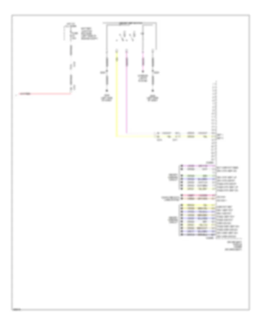 https://portal-diagnostov.com/license.html
Automotive Electricians Portal FZCO
Automotive Electricians Portal FZCO
https://portal-diagnostov.com/license.html
https://portal-diagnostov.com/license.html
Automotive Electricians Portal FZCO
Automotive Electricians Portal FZCOList of elements for Driver"s Memory Seat Wiring Diagram (2 of 2) for Ford Edge Limited 2013:
- Battery junction box (bjb) (left side of engine compt)
- C212
- C213
- C311
- C3299c
- C3299d
- Computer data lines system
- Cpm16
- Cpm17
- Cpm20
- Cpm21
- Cpm23
- Cpm26
- Cpm28
- Cpm29
- Cpm31
- Cpm33
- Cpm34
- Cps15
- Cps16
- Driver seat module (under driver's seat)
- Drv hor pot
- Drv mirr hor sw
- Drv mirr vert sw
- Drv mtr hor rt
- Drv mtr vert dn
- Drv mtr vert up
- Drv vert pot
- Ext mirr pot feed
- Fuse 30a
- G205 (left side of dash)
- Hot at all times
- Interior lights system
- Lpm30
- Memory mirrors circuit
- Memory set switch
- Mirr com sw
- Mirr pot ret
- Ms can +
- Ms can -
- Pass hor pot
- Pass mirr hor sw
- Pass mirr vert sw
- Pass mtr hor rt
- Pass mtr vert dn
- Pass mtr vert up
- Pass vert pot
- Rpm30
- S208
- Set 1
- Set 2
- Vdb06
- Vdb07
- Vpm35
- Vpm36
- Vpm37
- Vpm38
Memory Mirrors Wiring Diagram for Ford Edge Limited 2013
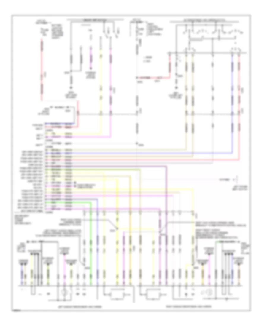 https://portal-diagnostov.com/license.html
Automotive Electricians Portal FZCO
Automotive Electricians Portal FZCO
https://portal-diagnostov.com/license.html
https://portal-diagnostov.com/license.html
Automotive Electricians Portal FZCO
Automotive Electricians Portal FZCOList of elements for Memory Mirrors Wiring Diagram for Ford Edge Limited 2013:
- (body main wiring harness, near breakout to c312)
- (body main wiring harness, near breakout to restraints control module)
- (left front window regulator wiring harness, near breakout to exterior rear view mirror switch)
- (right front window regulator wiring harness, near breakout to right exterior rear view mirror switch)
- Battery junction box (bjb) (left side of engine compt)
- Body control module (bcm) (left kick panel)
- C212
- C213
- C2280d
- C311
- C3299a
- C3299b
- C3299c
- C3299d
- C510
- C610
- Computer data lines system
- Cpm16
- Cpm17
- Cpm20
- Cpm21
- Cpm23
- Cpm26
- Cpm28
- Cpm29
- Cpm31
- Cpm33
- Cpm34
- Cps15
- Cps16
- Defogger system
- Driver seat module (under driver's seat)
- Drv mirr horz pot
- Drv mirr horz sw
- Drv mirr mtr horz rt
- Drv mirr mtr vert dn
- Drv mirr mtr vert up
- Drv mirr vert pot
- Drv mirr vert sw
- Edge
- Ext mirr pot feed
- Exterior lights system
- Exterior rear view mirror switch
- Fuse 30a
- Fuse 7.5a
- G201 (lower left "a" pillar)
- G202 (lower right "a" pillar)
- G205 (left side of dash)
- G302 (right "b" pillar)
- Gd145
- Hot at all times
- Interior lights system
- Left power seat switch
- Left side exterior rear view mirror
- Lpm30
- Memory set switch
- Mirr com sw
- Mirr pot ret
- Mirrors system
- Mkx
- Ms can +
- Ms can -
- Navigation system
- Nca
- Pass mirr horz pot
- Pass mirr horz sw
- Pass mirr vert pot
- Pass mirr vert sw
- Pass mtr horz rt
- Pass mtr vert dn
- Pass mtr vert up
- Pwr gnd
- Right side exterior rear view mirror
- Rpm30
- S208
- S302
- S320
- S322
- S343
- S344
- S502
- S505
- S604
- S606
- Sbb23
- Sbp07
- Set 1
- Set 2
- Vbatt
- Vdb06
- Vdb07
- Vpm35
- Vpm36
- Vpm37
- Vpm38
Steering Column Memory Wiring Diagram for Ford Edge Limited 2013
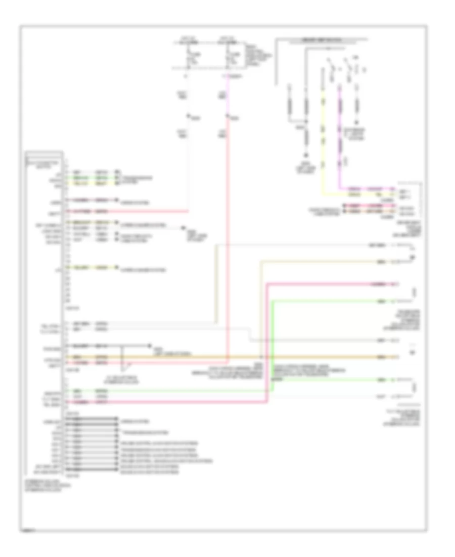 https://portal-diagnostov.com/license.html
Automotive Electricians Portal FZCO
Automotive Electricians Portal FZCO
https://portal-diagnostov.com/license.html
https://portal-diagnostov.com/license.html
Automotive Electricians Portal FZCO
Automotive Electricians Portal FZCOList of elements for Steering Column Memory Wiring Diagram for Ford Edge Limited 2013:
- (main wiring harness, near breakout to adjustable steering column motor (telescope)) s292
- A/d 1
- A/d 2
- A/d 3
- A/d 4
- Body control module (bcm) (left kick panel)
- C213
- C2280a
- C2414a
- C2414b
- C2414c
- C2414d
- C311
- C3299c
- C3299d
- Cet42
- Cet43
- Computer data lines system
- Cpp02
- Cpp04
- Cpp22
- Cps15
- Cps16
- Crh04
- Cruise control & navigation systems
- Cruise control, sound & navigation systems
- Crw15
- Down
- Driver seat module (under driver's seat)
- Dwn
- Frt wiper hi
- Fuse 15a
- G205 (left side of dash)
- Gd115
- Horn
- Horn sw
- Horns system
- Hot at all times
- Hs can+
- Hs can-
- Interior lights system
- Lin
- Logic gnd
- Memory set switch
- Ms can+
- Ms can-
- Mtr com
- Multi-function switch
- Nca
- Pwr gnd
- Re407
- Rpp06
- Rtn
- S228
- S229
- S293 (main wiring harness, near breakout to adjustable steering column motor (telescope))
- Sbp23
- Sbp24
- Set 1
- Set 2
- Sig
- Sns rtn
- Sound & navigation systems
- Steering column control module (sccm) (steering column)
- Sw gnd left
- Sw gnd right
- Tel mtr+/-
- Tel sns+
- Telescope adjustable steering column motor (steering column)
- Tilt adjustable steering column motor (steering column)
- Tilt mtr+/-
- Tilt sns+
- Transmissions & navigation systems
- Transmissions system
- Vbatt
- Vdb04
- Vdb05
- Vdb06
- Vdb07
- Vdn05
- Vpp08
- Vpp17
- W/ adjustable steering column
- Wiper/washer system
NAVIGATION
Blind Spot Information System Wiring Diagram for Ford Edge Limited 2013
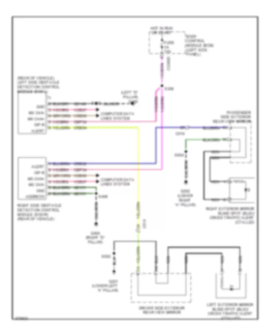 https://portal-diagnostov.com/license.html
Automotive Electricians Portal FZCO
Automotive Electricians Portal FZCO
https://portal-diagnostov.com/license.html
https://portal-diagnostov.com/license.html
Automotive Electricians Portal FZCO
Automotive Electricians Portal FZCOList of elements for Blind Spot Information System Wiring Diagram for Ford Edge Limited 2013:
- (left "d" pillar) g400
- (rear of vehicle) left side obstacle detection control module (sod-l)
- Address
- Alert
- Body control module (bcm) (left kick panel)
- C2280d
- C510
- C610
- Cbp34
- Computer data lines system
- Crb02
- Crb04
- Driver side exterior rear view mirror
- Fuse 10a
- G201 (lower left "a" pillar)
- G202 (lower right "a" pillar)
- G404 (right "d" pillar)
- Gd149
- Gd151
- Gnd
- Hot in run or start
- Isp-r
- Left exterior mirror blind spot (blis)/ cross traffic alert (cta) led
- Ms can+
- Ms can-
- Nca
- Passenger side exterior rear view mirror
- Right exterior mirror blind spot (blis)/ cross traffic alert (cta) led
- Right side obstacle detection control module (sod-r) (rear of vehicle)
- S308
- S402
- S408
- S502
- S604
- Vdb06
- Vdb07
Navigation Wiring Diagram, with Premium (1 of 2) for Ford Edge Limited 2013
 https://portal-diagnostov.com/license.html
Automotive Electricians Portal FZCO
Automotive Electricians Portal FZCO
https://portal-diagnostov.com/license.html
https://portal-diagnostov.com/license.html
Automotive Electricians Portal FZCO
Automotive Electricians Portal FZCOList of elements for Navigation Wiring Diagram, with Premium (1 of 2) for Ford Edge Limited 2013:
- (w/ satellite radio)
- 2.0l
- Am/fm
- Ant pwr
- Antenna module (right kick panel)
- Antenna pwr
- Audio control module (acm) (center of dash)
- Audio input jack (w/o sync)
- Battery junction box (bjc) (left side of engine compt)
- C1381b
- C175b
- C213
- C215
- C219
- C3053
- C510
- C610
- C700
- C800
- Cdc26
- Coaxial cable
- Computer data lines system
- Dme45
- Except 2.0l
- G206 (left side of dash)
- Gd114
- Gnd
- I can+
- I can-
- Left front speaker
- Left rear speaker
- Lf spkr +
- Lf spkr-
- Lr spkr +
- Lr spkr-
- Nca
- Powertrain control module (pcm) (right side of engine compt)
- Rf spkr +
- Rf spkr-
- Right front speaker
- Right rear speaker
- Rme07
- Rme09
- Rme10
- Rme12
- Rme45
- Rr spkr+
- Rr spkr-
- Sbp29
- Sdars
- Shield
- Smcs
- Solid state
- St in 2l +
- St in 2l -
- St in 2r +
- St input 2l+
- St input 2l-
- St input 2r+
- Start
- Starter relay
- Vbatt
- Vdb13
- Vdb14
- Vme07
- Vme09
- Vme10
- Vme12
- Vme43
- Vme45
- Vme46
Navigation Wiring Diagram, with Premium (2 of 2) for Ford Edge Limited 2013
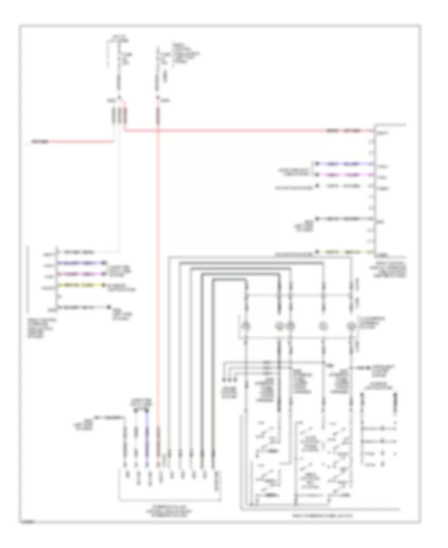 https://portal-diagnostov.com/license.html
Automotive Electricians Portal FZCO
Automotive Electricians Portal FZCO
https://portal-diagnostov.com/license.html
https://portal-diagnostov.com/license.html
Automotive Electricians Portal FZCO
Automotive Electricians Portal FZCOList of elements for Navigation Wiring Diagram, with Premium (2 of 2) for Ford Edge Limited 2013:
- A/d1
- A/d2
- A/d3
- A/d4
- Body control module (bcm) (left kick panel)
- C218b
- C218c
- C2280a
- C2414a
- C2414d
- Clockspring (steering column)
- Cls32
- Computer data lines system
- Cruise control system
- Down
- Exterior lights system
- Front control interface module (fcim) (center of dash)
- Front control/ display interface module (fcdim) (center of dash)
- Fuse 15a
- Fuse 20a
- G205 (left side of dash)
- Gd115
- Gnd
- Haz sw
- Hot at all times
- Hs can+
- Hs can-
- I can +
- I can -
- Instrument cluster system
- Interior lights system
- Left
- Media (w/o sync) ppt (w/ sync)
- Mute (w/o sync) phone (w/ sync)
- Navigation system
- Nca
- Rh sw gnd
- Right
- Right steering wheel switch
- Rmp19
- S222
- S229
- S291 (steering wheel jumper wiring harness)
- S294
- S295 (steering wheel jumper wiring harness)
- S296 (steering wheel jumper wiring harness)
- Sbp23
- Sbp29
- Seek+
- Seek-
- Steering column control module (sccm) (steering column)
- Vbatt
- Vdb04
- Vdb05
- Vdb13
- Vdb14
- Video+
- Video-
- Vmp19
- Vol+
- Vol-
Navigation Wiring Diagram, with Sony (1 of 2) for Ford Edge Limited 2013
 https://portal-diagnostov.com/license.html
Automotive Electricians Portal FZCO
Automotive Electricians Portal FZCO
https://portal-diagnostov.com/license.html
https://portal-diagnostov.com/license.html
Automotive Electricians Portal FZCO
Automotive Electricians Portal FZCOList of elements for Navigation Wiring Diagram, with Sony (1 of 2) for Ford Edge Limited 2013:
- (near breakout to g403) s415
- (near breakout to g403) s416
- Audio digital signal processing (dsp) module (right "c" pillar)
- Audio in left+
- Audio in left-
- Audio in right+
- Audio in right-
- C219
- C4326a
- C4326b
- C4326c
- C510
- C610
- C700
- C800
- Cntr ip spkr+
- Cntr ip spkr-
- Computer data lines system
- D pillar twtr +
- D pillar twtr -
- Enable
- Front control/ display interface module (fcdim) (center of dash)
- G205 (left side of dash)
- G403 (left side of cargo area)
- Gd115
- Gd148
- Gnd
- I can +
- I can -
- Instrument panel speaker
- La-pillar spkr +
- La-pillar spkr -
- Left front speaker
- Left front tweeter
- Left rear speaker
- Left rear tweeter
- Lf spkr +
- Lf spkr -
- Lr spkr +
- Lr spkr -
- Navigation system
- Nca
- Ra-pillar spkr +
- Ra-pillar spkr -
- Rf spkr +
- Rf spkr-
- Right front speaker
- Right front tweeter
- Right rear speaker
- Right rear tweeter
- Rme01
- Rme02
- Rme06
- Rme07
- Rme08
- Rme09
- Rme10
- Rme11
- Rme12
- Rme18
- Rme39
- Rme58
- Rme80
- Rmp19
- Rr spkr+
- Rr spkr-
- S407
- Sbp19
- Sbp29
- Sme23
- Subw 1+
- Subw 2 +
- Subw1-
- Subw2-
- Subwoofer
- Sync alert+
- Sync alert-
- Vbatt
- Vdb13
- Vdb14
- Video+
- Video-
- Vme01
- Vme02
- Vme06
- Vme07
- Vme08
- Vme09
- Vme10
- Vme11
- Vme12
- Vme18
- Vme39
- Vme58
- Vme80
- Vmp19
Navigation Wiring Diagram, with Sony (2 of 2) for Ford Edge Limited 2013
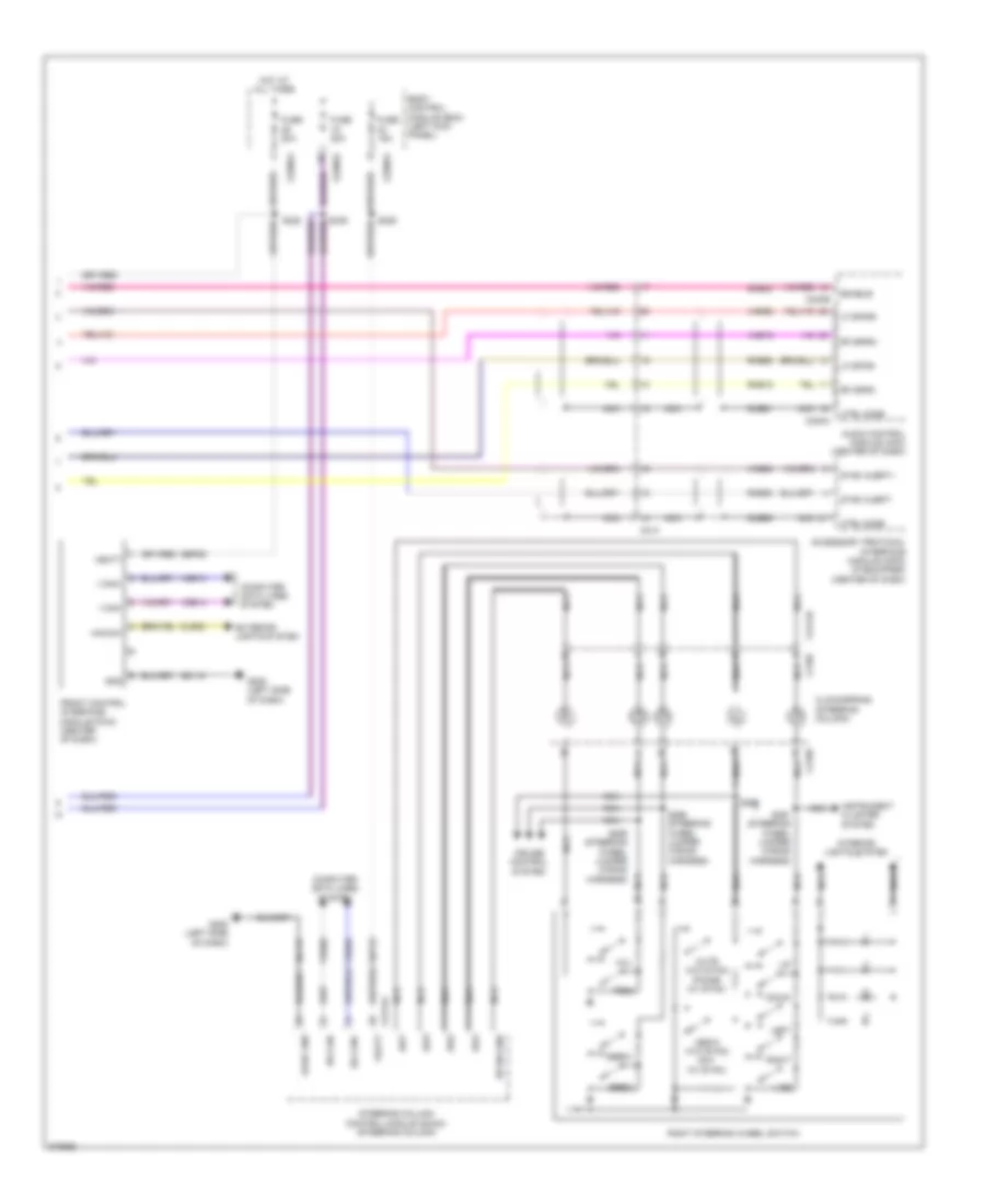 https://portal-diagnostov.com/license.html
Automotive Electricians Portal FZCO
Automotive Electricians Portal FZCO
https://portal-diagnostov.com/license.html
https://portal-diagnostov.com/license.html
Automotive Electricians Portal FZCO
Automotive Electricians Portal FZCOList of elements for Navigation Wiring Diagram, with Sony (2 of 2) for Ford Edge Limited 2013:
- A/d1
- A/d2
- A/d3
- A/d4
- Accessory protocol interface module (apim) (if equipped) (center of dash)
- Audio control module (acm) (center of dash)
- Body control module (bcm) (left kick panel)
- C214
- C218b
- C218c
- C2280a
- C2280d
- C240a
- C240b
- C2414a
- C2414d
- Clockspring (steering column)
- Cls32
- Computer data lines system
- Cruise control system
- Ctrl mode
- Dme50
- Dme51
- Down
- Enable
- Exterior lights system
- Front control interface module (fcim) (center of dash)
- Fuse 15a
- Fuse 20a
- G205 (left side of dash)
- Gd115
- Gnd
- Haz sw
- Hot at all times
- Hs can+
- Hs can-
- I can+
- I can-
- Instrument cluster system
- Interior lights system
- Left
- Lf spkr+
- Lf spkr-
- Logic gnd
- Media (w/o sync) ppt (w/ sync)
- Mute (w/o sync) phone (w/ sync)
- Nca
- Rf spkr+
- Rf spkr-
- Rh sw gnd
- Right
- Right steering wheel switch
- Rme18
- Rme58
- Rme80
- S229
- S291 (steering wheel jumper wiring harness)
- S294
- S295 (steering wheel jumper wiring harness)
- S296 (steering wheel jumper wiring harness)
- Sbp23
- Sbp29
- Seek+
- Seek-
- Sme23
- Steering column control module (sccm) (steering column)
- Sync alert+
- Sync alert-
- Vbatt
- Vdb04
- Vdb05
- Vdb13
- Vdb14
- Vme18
- Vme58
- Vme80
- Vol+
- Vol-
Parking Assistant Wiring Diagram for Ford Edge Limited 2013
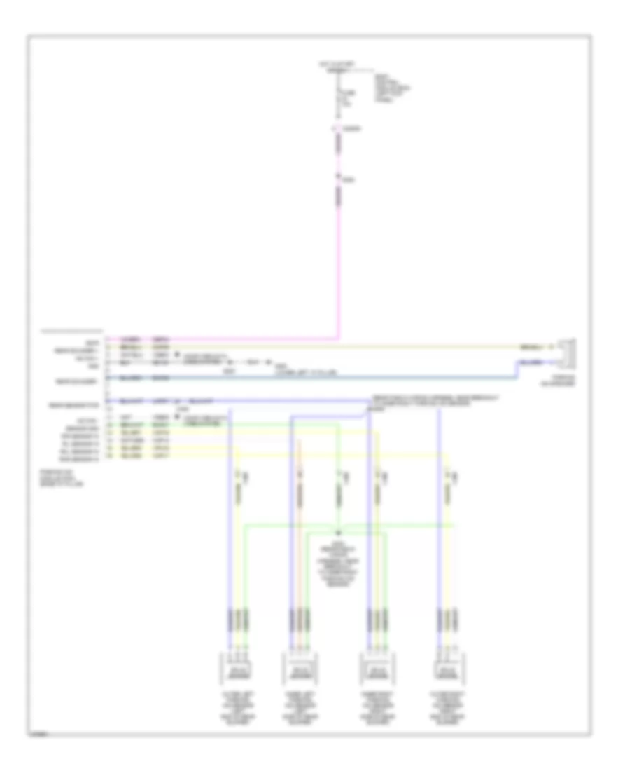 https://portal-diagnostov.com/license.html
Automotive Electricians Portal FZCO
Automotive Electricians Portal FZCO
https://portal-diagnostov.com/license.html
https://portal-diagnostov.com/license.html
Automotive Electricians Portal FZCO
Automotive Electricians Portal FZCOList of elements for Parking Assistant Wiring Diagram for Ford Edge Limited 2013:
- (rear fascia wiring harness, near breakout to inner right parking aid sensor) s405
- Body control module (bcm) (left kick panel)
- C2280d
- C406
- Cbp34
- Cmp09
- Computer data lines system
- Fuse 10a
- G200 (lower left "a" pillar)
- Gd133
- Gnd
- Hot in start or run
- Hs can +
- Hs can -
- Inner left parking aid sensor (left side of rear bumper)
- Inner right parking aid sensor (right side of rear bumper)
- Isd-r
- Lmp07
- Outer left parking aid sensor (left end of rear bumper)
- Outer right parking aid sensor (right end of rear bumper)
- Parking aid module (pam) (base "d" pillar)
- Parking aid speaker
- Rear sensor pwr
- Rear sounder +
- Rear sounder -
- Ril sensor in
- Rir sensor in
- Rmp07
- Rmp09
- Rol sensor in
- Ror sensor in
- S200
- S308
- S403 (rear fascia wiring harness, near breakout to inner right parking aid sensor)
- Sensor gnd
- Solid state
- Vdb04
- Vdb05
- Vmp14
- Vmp16
- Vmp17
- Vpm15
Rear Camera Wiring Diagram for Ford Edge Limited 2013
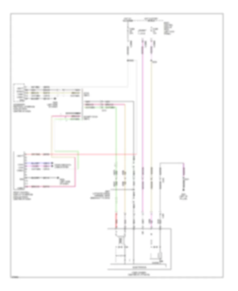 https://portal-diagnostov.com/license.html
Automotive Electricians Portal FZCO
Automotive Electricians Portal FZCO
https://portal-diagnostov.com/license.html
https://portal-diagnostov.com/license.html
Automotive Electricians Portal FZCO
Automotive Electricians Portal FZCOList of elements for Rear Camera Wiring Diagram for Ford Edge Limited 2013:
- Accessory protocol interface module (apim) (center of dash)
- Body control module (bcm) (left kick panel)
- C213
- C2280b
- C2280c
- C2280d
- C495
- C919
- Choke
- Computer data lines system
- Dmn19
- Electronics
- Except sync gen 2
- Front control/ display interface module (fcdim) (center of dash)
- Fuse 10a
- Fuse 20a
- G205 (left side of dash)
- G301 (left "b" pillar)
- Gd115
- Gnd
- Hot at all times
- Hot in start or run
- I can+
- I can-
- Lin
- Lin 03
- Micro
- Nca
- Red
- Rmp19
- S222
- S308
- S341
- S907 (liftgate wiring harness, near breakout to c919)
- Sbp29
- Shield
- Sync gen 2
- Vbatt
- Vdb13
- Vdb14
- Video camera (center of liftgate)
- Video+
- Video-
- Vmp19
POWER DISTRIBUTION
Power Distribution Wiring Diagram (1 of 7) for Ford Edge Limited 2013
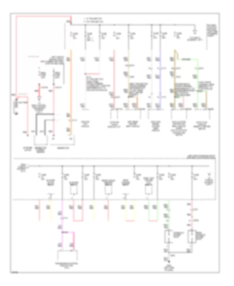 https://portal-diagnostov.com/license.html
Automotive Electricians Portal FZCO
Automotive Electricians Portal FZCO
https://portal-diagnostov.com/license.html
https://portal-diagnostov.com/license.html
Automotive Electricians Portal FZCO
Automotive Electricians Portal FZCOList of elements for Power Distribution Wiring Diagram (1 of 7) for Ford Edge Limited 2013:
- (left side of engine compt) battery junction box (bjb)
- (left side of engine compt) high current battery junction box (bjb)
- (main wiring harness, near breakout to hvac module) s207
- Anti-lock brake system (abs) module
- Battery
- Battery junction box (bjb) (left side of engine compt)
- Blower motor relay
- C110
- C1617a
- C1617b
- C212
- C215
- C228b
- C300
- C3036a
- C3053
- C316
- C3162a
- C4174a
- Console 2 power point
- Cooling fan module
- Datc hvac module (edge w/ heated seats)
- Dual climate controlled seat module (dcsm) (mkx w/ climate controlled seats)
- From fuse 28 a (diagram 1 of 7)
- Fuse 10a
- Fuse 15a
- Fuse 20a
- Fuse 25a
- Fuse 30a
- Fuse 40a
- Fuse 40a 60a
- G205 (left side of dash)
- Generator
- Generator current sensor
- Left rear heated seat module
- Liftgate/ trunk module (ltm)
- Mega fuse 120a
- Mega fuse 200a
- Nca
- Park lamp trailer tow relay
- Rear console power point
- Rear washer relay
- Rear window defrost relay
- Red
- S112 (w/ trailer tow) (dash panel wiring harness, to headlight junction, near breakout to cooling fan module)
- S182
- S349
- Starter motor
- Starter relay
- To body control module (bcm) (diagram 3 of 7)
- To fuse 18 (diagram 1 of 7)
- To fuse 86 (diagram 2 of 7)
- Transmission control module (tcm) (2.0l)
- W/ trailer tow
- W/o trailer tow
Power Distribution Wiring Diagram (2 of 7) for Ford Edge Limited 2013
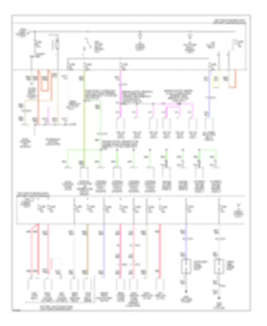 https://portal-diagnostov.com/license.html
Automotive Electricians Portal FZCO
Automotive Electricians Portal FZCO
https://portal-diagnostov.com/license.html
https://portal-diagnostov.com/license.html
Automotive Electricians Portal FZCO
Automotive Electricians Portal FZCOList of elements for Power Distribution Wiring Diagram (2 of 7) for Ford Edge Limited 2013:
- (dash panel to headlight junction wiring harness, near breakout to cooling fan module) s113
- (engine control sensor & fuel charge wiring harness, near breakout to fuel injector 3) s128
- (engine control sensor & fuel charge wiring harness, near breakout to fuel injector 3) s131
- (engine control sensor & fuel charge wiring harness, near breakout to powertrain control module) s124
- (if equipped)
- (left side of engine compt) battery junction box (bjb)
- (near breakout to c140) s117
- 2.0l
- A/c clutch relay
- All wheel drive (awd) relay module
- Battery junction box (bjb) (left side of engine compt)
- Brake pedal position (bpp) switch
- C140
- C175b
- C210
- C212
- C215
- C925
- Cargo area power point
- Coil on plug (cop) 1
- Coil on plug (cop) 2
- Coil on plug (cop) 3
- Coil on plug (cop) 4
- Coil on plug (cop) 5
- Coil on plug (cop) 6
- Evap canister purge valve
- Evap canister vent solenoid
- Except 2.0l
- From c fuse 62 (diagram 2 of 7)
- From fuse 9 b (diagram 1 of 7)
- Fuel pump relay
- Fuse 10a
- Fuse 15a
- Fuse 20a
- Fuse 7.5a
- G205 (left side of dash)
- G400 (left "d" pillar)
- Heated oxygen sensor (ho2s) 12
- Heated oxygen sensor (ho2s) 22
- Instrument panel power point
- Left headlamp (w/ hid)
- Left turn trailer tow relay
- Mass air flow/intake air temperature (maf/iat) sensor
- Nca
- Pcm power relay (except 2.0l)
- Powertrain control module (pcm)
- Rear seat release relay
- Rear window wiper motor
- Red
- Right headlamp (w/ hid)
- Right turn trailer tow relay
- Roof opening panel motor assembly
- S402
- Stop lamp relay (edge)
- To fuse 65 (diagram 2 of 7)
- To fuse 87 (diagram 3 of 7)
- To pcm power relay (diagram 7 of 7)
- Universal heated oxygen sensor (ho2s) 11
- Universal heated oxygen sensor (ho2s) 21
- Variable camshaft timing 11 (vct11) solenoid
- Variable camshaft timing 12 (vct12) solenoid
- Variable camshaft timing 21 (vct21) solenoid
- Variable camshaft timing 22 (vct22) solenoid
Power Distribution Wiring Diagram (3 of 7) for Ford Edge Limited 2013
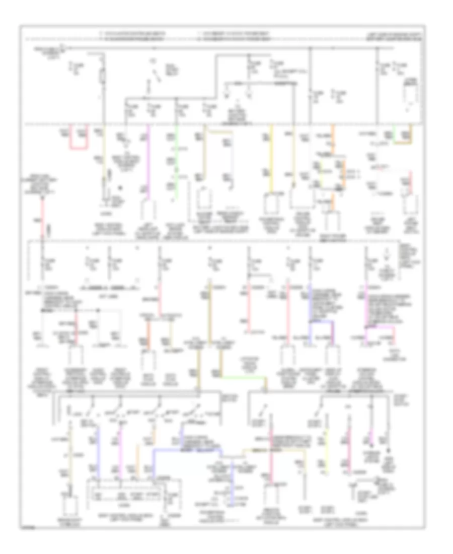 https://portal-diagnostov.com/license.html
Automotive Electricians Portal FZCO
Automotive Electricians Portal FZCO
https://portal-diagnostov.com/license.html
https://portal-diagnostov.com/license.html
Automotive Electricians Portal FZCO
Automotive Electricians Portal FZCOList of elements for Power Distribution Wiring Diagram (3 of 7) for Ford Edge Limited 2013:
- (2.0l)
- (except 2.0l)
- (left side of engine compt) battery junction box (bjb)
- (not used)
- (w/ sync gen 2)
- 2.0l
- Acc
- Acc/ run
- Accessory protocol interface module (apim) (w/ sync gen 1 & 2)
- Anti-lock brake system (abs) module
- Audio control module (acm)
- Automatic a/c
- Battery junction box (bjb) (left side of engine compt)
- Blower motor relay
- Body control module (bcm) (left kick panel)
- Brake shift interlock
- C110
- C1381b
- C175b
- C212
- C215
- C2153c
- C2280a
- C2280b
- C2280d
- C2280e
- C2280f
- C2280g
- C228a
- C240a
- C2414b
- C3053
- C311
- C315
- C316
- C3299a
- C4174a
- Cruise control module (ccm) (w/ adaptive cruise)
- Data link connector
- Datc hvac module
- Driver seat module (dsm) (w/ memory)
- Emtc hvac module
- Except 2.0l
- From fuse 18 (diagram 6 of 7)
- From fuse 21 d (diagram 2 of 7)
- From high current battery junction box (bjb) (diagram 1 of 7)
- Front control/ display interface module (fcdim) (w/o sync gen 2)
- Front controls interface module (fcim)
- Fuse 10a
- Fuse 10a 5a
- Fuse 15a
- Fuse 20a
- Fuse 30a
- Fuse 5a
- G205 (left side of dash)
- Global positioning system module (gpsm)
- Harness, near breakout to g205) s285
- Head up display (hud) module (w/ adaptive cruise)
- Ignition switch
- Instrument panel cluster (ipc)
- Interior lights system
- Key in
- Key in ignition
- Left headlamp (w/ adaptive headlamps)
- Left power seat switch
- Liftgate/ trunk module (ltm)
- Lock
- Manual a/c
- Micro
- Nca
- Not used
- Off
- Powertrain control module (pcm)
- Rear window defrost relay
- Red
- Remote function actuator (rfa) module
- Right power seat switch
- Run
- Run/ start (fet)
- Run/ start relay
- Start
- Start/ run
- Start/ stop (led) (fet)
- Start/ stop 1
- Start/ stop 2
- Start/ stop switch
- Steering column control module (sccm) (w/ adjustable steering column)
- To battery junction box (bjb) (diagram 7 of 7)
- To body control module (bcm) (diagram 5 of 7)
- To fuse 27 (diagram 4 of 7)
- W/ climate controled seats
- W/ intelligent access
- W/o climate controled seats
- W/o intelligent access
- W/o memory w/ 10-way power seat
- W/o memory w/ 6-way power seat
- Wiper relay
Power Distribution Wiring Diagram (4 of 7) for Ford Edge Limited 2013
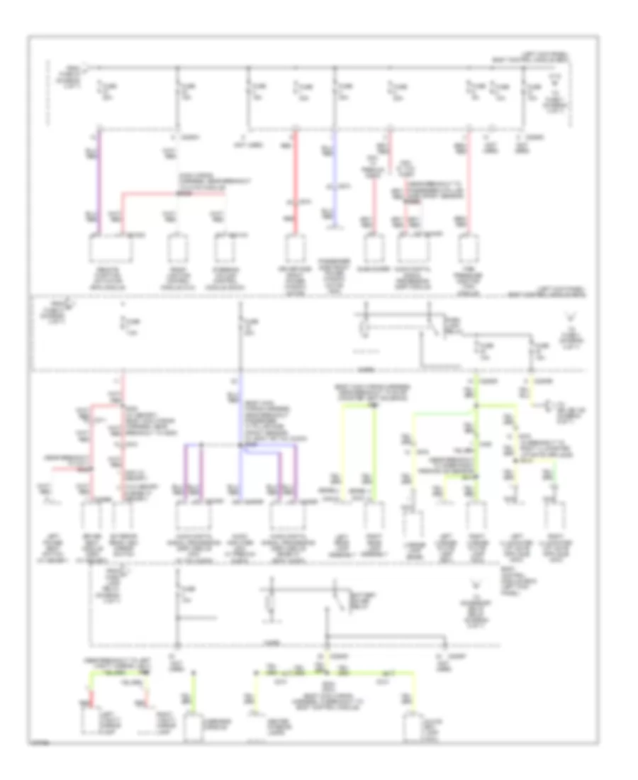 https://portal-diagnostov.com/license.html
Automotive Electricians Portal FZCO
Automotive Electricians Portal FZCO
https://portal-diagnostov.com/license.html
https://portal-diagnostov.com/license.html
Automotive Electricians Portal FZCO
Automotive Electricians Portal FZCOList of elements for Power Distribution Wiring Diagram (4 of 7) for Ford Edge Limited 2013:
- & edge w/ memory)
- (body main wiring harness, near breakout passenger "c" pillar side impact sensor) (w/ sony or thx audio) s339
- (body main wiring harness, near breakout to evap canister vent solenoid) s321
- (edge)
- (left kick panel) body control module (bcm)
- (main wiring harness, near breakout to hvac module) s229
- (mkx w/ memory)
- (mkx)
- (near breakout to c311) s322
- (near breakout to inner right parking aid sensor) s413
- (near breakout to left vanity mirror light) s901
- (not used)
- (w/o memory
- Audio amplifier (mkx w/ premium audio)
- Audio digital signal processing (dsp) module
- Audio digital signal processing (dsp) module (edge w/ sony audio)
- Audio digital signal processing (dsp) module (mkx w/ thx audio)
- Battery saver relay
- Body control module (bcm) (left kick panel)
- C210
- C213
- C2153c
- C2280a
- C2280d
- C2280e
- C2280f
- C2414a
- C311
- C3299b
- C406
- C4326c
- C4348c
- C4364b
- C510
- C610
- C919
- Center interior lamps
- Driver seat module (dsm) (w/ memory)
- Driver side front power window motor
- Exterior rear view mirror switch
- From f fuse 24 (diagram 3 of 7)
- From g fuse 21 (diagram 4 of 7)
- From h park lamp relay (diagram 4 of 7)
- Front lighting control module (flm)
- Fuse 10a
- Fuse 15a
- Fuse 20a
- Fuse 30a
- Fuse 5a
- Fuse 7.5a
- Glove box lamp (mkx)
- Left license plate lamp (mkx)
- Left power seat switch (w/ memory)
- Left rear lamp assembly
- Left vanity mirror lamp
- License lamp (edge)
- Micro
- Mkx w/ premium audio
- Mkx w/ thx audio
- Nca
- Overhead console
- Park lamp relay
- Passenger side front power window motor (mkx)
- Red
- Remote function actuator (rfa) module
- Right license plate lamp (mkx)
- Right rear lamp assembly
- Right vanity mirror lamp
- S234 (mkx) (body main wiring harness, in breakout to body control module)
- Side impact sensor) s360
- Steering column control module (sccm)
- Subwoofer
- Tire pressure monitor (tpm) module
- To accessory delay relay (diagram 5 of 7)
- To fuse 4 (diagram 4 of 7)
- To fuse 7 (diagram 4 of 7)
- To splice 109 (diagram 6 of 7)
Power Distribution Wiring Diagram (5 of 7) for Ford Edge Limited 2013
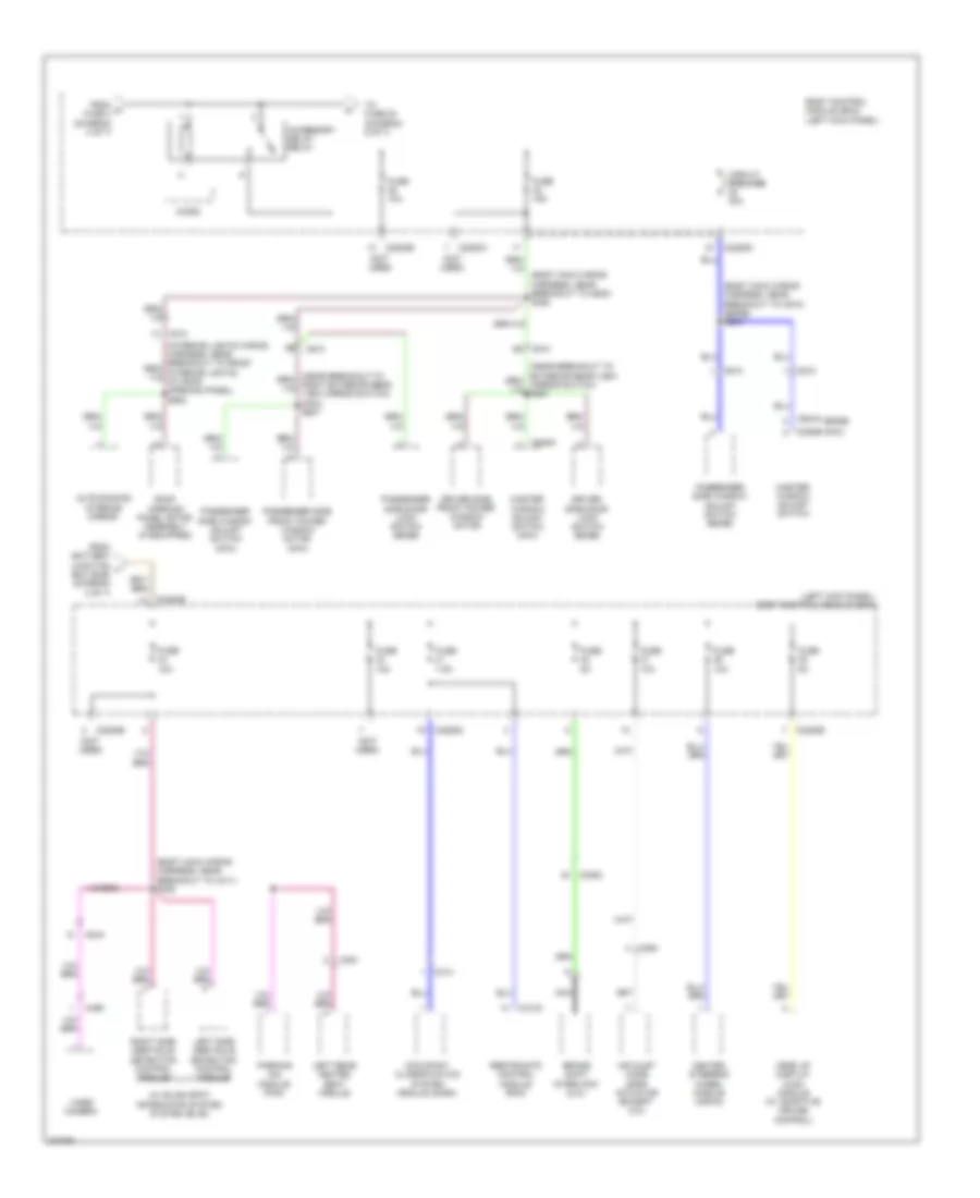 https://portal-diagnostov.com/license.html
Automotive Electricians Portal FZCO
Automotive Electricians Portal FZCO
https://portal-diagnostov.com/license.html
https://portal-diagnostov.com/license.html
Automotive Electricians Portal FZCO
Automotive Electricians Portal FZCOList of elements for Power Distribution Wiring Diagram (5 of 7) for Ford Edge Limited 2013:
- (body main wiring harness, near breakout to c311) s308
- (body main wiring harness, near breakout to c510) (edge) s254
- (body main wiring harness, near breakout to g200) s382
- (edge)
- (left kick panel) body control module (bcm)
- (mkx)
- (not used)
- (w/ blind spot information system system (blis))
- Accessory delay relay
- Air inlet mode door actuator (except 2.0l)
- Auto-dimming interior mirror
- Body control module (bcm) (left kick panel)
- Brake shift interlock (2.0l)
- C210
- C2280a
- C2280b
- C2280d
- C2280e
- C264
- C300
- C3053
- C310a
- C314
- C495
- C504a
- C510
- C535a
- C535b
- C610
- C919
- Circuit breaker 30a
- Driver side door lock switch (edge)
- Driver side front power window motor
- From battery junction j box (bjb) (diagram 3 of 7)
- From m fuse 4 (diagram 4 of 7)
- Fuse 10a
- Fuse 15a
- Fuse 5a
- Fuse 7.5a
- Head up display (hud) module (w/ adaptive cruise control)
- Heated steering wheel module (hswm)
- Left rear heated seat module
- Left side obstacle detection control module
- Master window adjust switch
- Master window adjust switch (mkx)
- Micro
- Nca
- Occupant classification system module (ocsm)
- Parking aid module (pam)
- Passenger side door lock switch (edge)
- Passenger side front power window motor (mkx)
- Passenger side window adjust switch (edge)
- Passenger side window adjust switch (mkx)
- Restraints control module (rcm)
- Right side obstacle detection control module
- Roof opening panel motor assembly (if equipped)
- To fuse 20 (diagram 6 of 7)
- Video camera
Power Distribution Wiring Diagram (6 of 7) for Ford Edge Limited 2013
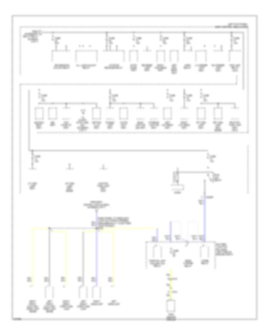 https://portal-diagnostov.com/license.html
Automotive Electricians Portal FZCO
Automotive Electricians Portal FZCO
https://portal-diagnostov.com/license.html
https://portal-diagnostov.com/license.html
Automotive Electricians Portal FZCO
Automotive Electricians Portal FZCOList of elements for Power Distribution Wiring Diagram (6 of 7) for Ford Edge Limited 2013:
- (left kick panel) body control module (bcm)
- 2nd row seat (fet)
- All lock/unlock relay
- Back lighting led (fet)
- Battery junction box (bjb) (left side of engine compt)
- Bsi (fet)
- C210
- C212
- C2280f
- Delay relay (diagram 5 of 7)
- Driver door unlock relay
- Fog lamp relay (mkx)
- From accessory k
- From body control module (bcm) (diagram 4 of 7)
- Fuse 10a
- Fuse 15a
- Fuse 20a
- Fuse 5a
- Horn relay
- Interior lighting (fet)
- Keypad illum (fet)
- Left front auxiliary park lamp (edge)
- Left front park/turn lamp
- Left headlamp
- Left high beam (fet)
- Left low beam (fet)
- Lf turn lamp (fet)
- Lh corner lamp (fet)
- Liftgate release relay
- Lr stop/ turn lamp (fet) (mkx)
- Lr turn lamp (fet) (edge)
- Micro
- Parking lamp trailer tow relay
- Pcm wake up (fet)
- Puddle lamp (fet)
- Rain sensor module
- Rear washer relay
- Reverse lamp (fet)
- Rf turn lamp (fet)
- Rh corner lamp (fet)
- Right front auxiliary park lamp (edge)
- Right front park/turn lamp
- Right headlamp
- Right high beam (fet)
- Right low beam (fet)
- Rr stop/ turn lamp (fet) (mkx)
- Rr turn lamp (fet) (edge)
- Run/ acc relay
- Stop/ chmsl (fet)
- To start/ stop (led) fet (duagram 3 of 7)
- White light (fet)
- Wiper relay
Power Distribution Wiring Diagram (7 of 7) for Ford Edge Limited 2013
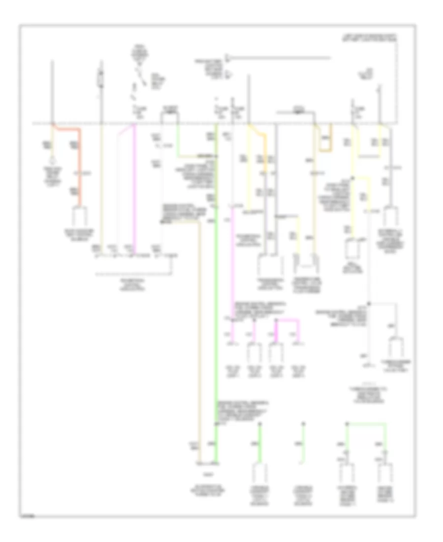 https://portal-diagnostov.com/license.html
Automotive Electricians Portal FZCO
Automotive Electricians Portal FZCO
https://portal-diagnostov.com/license.html
https://portal-diagnostov.com/license.html
Automotive Electricians Portal FZCO
Automotive Electricians Portal FZCOList of elements for Power Distribution Wiring Diagram (7 of 7) for Ford Edge Limited 2013:
- (engine control sensor & fuel charge wiring harness, near breakout to c140) s169
- (engine control sensor & fuel charge wiring harness, near breakout to coil on plug 1) s175
- (engine control sensor & fuel charge wiring harness, near breakout to variable camshaft timing 11 solenoid) s173
- (left side of engine compt) battery junction box (bjb)
- A/c clutch relay
- Atwu diode
- C110
- C1381b
- C1381e
- C140
- C212
- Coil on plug (cop) 1
- Coil on plug (cop) 2
- Coil on plug (cop) 3
- Coil on plug (cop) 4
- Evap conister vent control solenoid
- Evapcp diode
- Evaporative emition conister purge valve
- Externally controlled variable displacement compressor (evdc)
- From fuse 86 (diagram 2 of 7)
- From pcm power relay (diagram 2 of 7)
- Fuse 10a
- Fuse 15a
- Fuse 20a
- Grill shutter actuator
- Heated oxygen sensor (ho2s) 12
- Nca
- P from battery junction box (bjb) (diagram 3 of 7)
- Pcm power relay (2.0l)
- Powertrain control module (pcm)
- S108 (dash panel to headlight junction wiring harness, near breakout to battery junction box)
- S118 (dash panel to headlight junction wiring harness, near breakout to anti-theft hood switch)
- S172 (engine control sensor & fuel charge wiring harness, near breakout to c140)
- S181
- Temperature control valve transmission fluid warmer
- Transmission control module (tcm)
- Turbocharger (tc) wastegate regulating valve solenoid
- Turbocharger bypass valve (tcby)
- Universal heated oxygen sensor (ho2s) 11
- Variable camshaft timing 11 (vct11) solenoid
- Variable camshaft timing 12 (vct12) solenoid
POWER DOOR LOCKS
Power Door Locks Wiring Diagram, with Intelligent Access (1 of 3) for Ford Edge Limited 2013
 https://portal-diagnostov.com/license.html
Automotive Electricians Portal FZCO
Automotive Electricians Portal FZCO
https://portal-diagnostov.com/license.html
https://portal-diagnostov.com/license.html
Automotive Electricians Portal FZCO
Automotive Electricians Portal FZCOList of elements for Power Door Locks Wiring Diagram, with Intelligent Access (1 of 3) for Ford Edge Limited 2013:
- (left side of dash) g205
- (lower left "a" pillar) g201
- 2.0l
- Accessory delay relay
- All lock
- Ant+
- Ant-
- Backup tranceiver
- Body control module (bcm) (left kick panel)
- Bpp
- C1381b
- C175b
- C213
- C2153c
- C2153d
- C219
- C2280a
- C2280c
- C2280d
- C3053
- C510
- C610
- Ccb08
- Clock
- Computer data lines system
- Cpk19
- Cpk23
- Cpk28
- Cpk34
- Cpl11
- Cpl51
- Cpl52
- Cpl84
- Data
- Door lock
- Door unlock
- Dr door unlock
- Driver side door lock switch
- Edge
- Except 2.0l
- Exterior lights system
- Fuse 15a
- Fuse 20a
- G202 (lower right "a" pillar)
- G205 (left side of dash)
- Gd115
- Gnd
- Hot at all times
- Hs can+
- Hs can-
- Interior lights system
- Keypad illum (fet)
- Liftgate release
- Lock
- Logic gnd
- Lpk32
- Micro
- Mkx
- Passenger side door lock switch
- Powertrain control module (pcm) (right side of engine compt)
- Pwr gnd
- Remote function actuator (rfa) module (behind glove box)
- Right front door lock actuator
- Right front exterior door handle
- Rpk32
- Rpk39
- S229
- S252 (body main wiring harness, near breakout to c510)
- S253 (body main wiring harness, near breakout to c510)
- S370 (body main wiring harness, near breakout to g200)
- S382
- S502
- S507
- S604
- Sbp23
- Sbp27
- Start/stop1
- Starting/charging system
- Trunk, tailgate, fuel doors system
- Unlock
- Vbatt
- Vdb04
- Vdb05
- Vpk32
- Vpk33
- Vpk39
- Vpk40
Power Door Locks Wiring Diagram, with Intelligent Access (2 of 3) for Ford Edge Limited 2013
 https://portal-diagnostov.com/license.html
Automotive Electricians Portal FZCO
Automotive Electricians Portal FZCO
https://portal-diagnostov.com/license.html
https://portal-diagnostov.com/license.html
Automotive Electricians Portal FZCO
Automotive Electricians Portal FZCOList of elements for Power Door Locks Wiring Diagram, with Intelligent Access (2 of 3) for Ford Edge Limited 2013:
- (left "d" pillar)
- (not used)
- Ajar
- Anti-theft hood switch (right front of engine compt)
- Body control module (bcm) (left kick panel)
- C2280b
- C2280c
- C2280d
- C2280f
- C4174b
- C432
- C510
- C700
- C800
- C919
- Computer data lines system
- Cpl25
- Cpl26
- Cpl31
- Cpl36
- Cpl39
- Cpl45
- Cpl58
- Cpl84
- Fuse 15a
- G107 (right front of engine compt)
- G201 (lower left "a" pillar)
- G202 (lower right "a" pillar)
- G300 (behind left rear seat)
- G400
- Hood ajar
- Hot at all times
- Hs can+
- Hs can-
- Left front door lock actuator
- Left rear door lock actuator
- Lf door ajar
- Liftgate
- Liftgate latch (manual liftgate) (lower center of liftgate)
- Liftgate release relay
- Liftgate release switch (manual liftgate)
- Liftgate/trunk module (ltm) (base of left "d" pillar)
- Lr door ajar
- Manual liftgate
- Micro
- Ms can+
- Ms can-
- Nca
- Power liftgate
- Release
- Rf door ajar
- Right rear door lock actuator
- Rr door ajar
- S114
- S313 (body main wiring harness, near breakout to evap canister vent solenoid)
- S314 (body main wiring harness, near breakout to evap canister vent solenoid)
- S401
- S502
- S700
- S800
- Vdb04
- Vdb05
- Vdb06
- Vdb07
Power Door Locks Wiring Diagram, with Intelligent Access (3 of 3) for Ford Edge Limited 2013
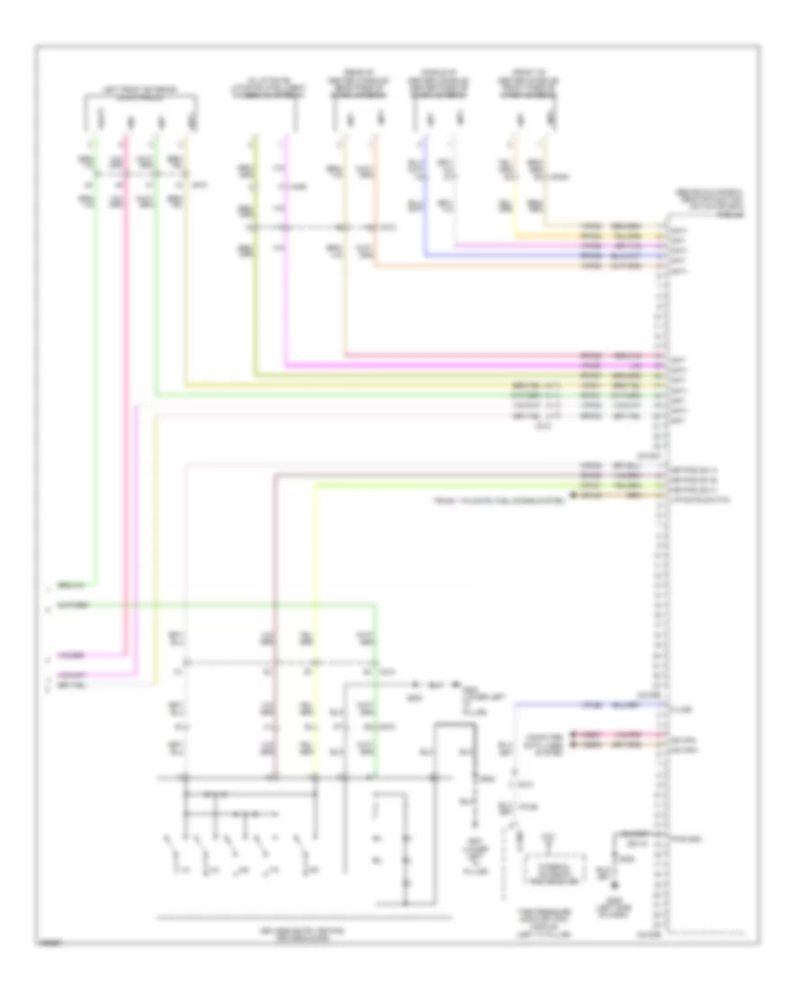 https://portal-diagnostov.com/license.html
Automotive Electricians Portal FZCO
Automotive Electricians Portal FZCO
https://portal-diagnostov.com/license.html
https://portal-diagnostov.com/license.html
Automotive Electricians Portal FZCO
Automotive Electricians Portal FZCOList of elements for Power Door Locks Wiring Diagram, with Intelligent Access (3 of 3) for Ford Edge Limited 2013:
- (behind glove box) remote function actuator (rfa) module
- (front of center console) front passive start antenna
- (in liftgate) liftgate intelligent access (ia) antenna
- (middle of center console) center passive start antenna
- (rear of center console) rear passive start antenna
- 1/2
- 3/4
- 5/6
- 7/8
- 9/0
- Ant+
- Ant-
- C213
- C2153a
- C2153b
- C2153e
- C3053
- C406
- C510
- Computer data lines system
- Cpk29
- Cpk30
- Cpk31
- Cpl45
- G200 (lower left "a" pillar)
- G201 (lower left "a" pillar)
- G205 (left side of dash)
- Gd115
- Gnd
- Internal antenna/ rke receiver
- K-line
- Keyless entry keypad (driver's door)
- Keypad sw a
- Keypad sw b
- Keypad sw c
- Left front exterior door handle
- Liftgate switch
- Ms can+
- Ms can-
- Pwr gnd
- Rpk01
- Rpk02
- Rpk05
- Rpk06
- Rpk07
- Rpk08
- S200
- S208
- S502
- Tire pressure monitor (tpm) module (left "c" pillar)
- Trunk, tailgate, fuel doors system
- Vbatt
- Vdb06
- Vdb07
- Vpk01
- Vpk02
- Vpk05
- Vpk06
- Vpk07
- Vpk08
- Vpl56
Power Door Locks Wiring Diagram, without Intelligent Access (1 of 2) for Ford Edge Limited 2013
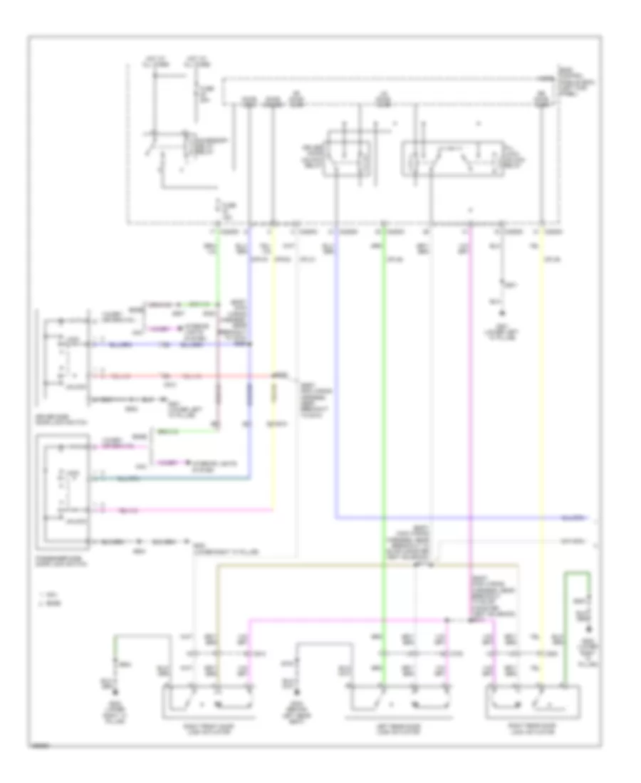 https://portal-diagnostov.com/license.html
Automotive Electricians Portal FZCO
Automotive Electricians Portal FZCO
https://portal-diagnostov.com/license.html
https://portal-diagnostov.com/license.html
Automotive Electricians Portal FZCO
Automotive Electricians Portal FZCOList of elements for Power Door Locks Wiring Diagram, without Intelligent Access (1 of 2) for Ford Edge Limited 2013:
- (body main wiring harness, near breakout to c510)
- (body main wiring harness, near breakout to c510) s253
- (body main wiring harness, near breakout to evap canister vent solenoid) s313
- (body main wiring harness, near breakout to evap canister vent solenoid) s314
- Accessory delay relay
- All lock/ unlock relay
- Body control micro module (bcm) (left kick panel)
- C2280c
- C2280d
- C510
- C610
- C700
- C800
- Cpk19
- Cpk23
- Cpl31
- Cpl36
- Cpl39
- Door lock
- Door unlock
- Driver door unlock relay
- Driver side door lock switch
- Edge
- Fuse 15a
- Fuse 20a
- G201 (lower left "a" pillar)
- G202 (lower right "a" pillar)
- G300 (behind left rear seat)
- Hot at all times
- Interior lights system
- Left rear door lock actuator
- Lock
- Lr door ajar
- Mkx
- Passenger side door lock switch
- Rf door ajar
- Right front door lock actuator
- Right rear door lock actuator
- Rr door ajar
- S201
- S252
- S382
- S502
- S507
- S604
- S700
- S800
- Unlock
Power Door Locks Wiring Diagram, without Intelligent Access (2 of 2) for Ford Edge Limited 2013
 https://portal-diagnostov.com/license.html
Automotive Electricians Portal FZCO
Automotive Electricians Portal FZCO
https://portal-diagnostov.com/license.html
https://portal-diagnostov.com/license.html
Automotive Electricians Portal FZCO
Automotive Electricians Portal FZCOList of elements for Power Door Locks Wiring Diagram, without Intelligent Access (2 of 2) for Ford Edge Limited 2013:
- (not used)
- 1/2
- 3/4
- 5/6
- 7/8
- 9/0
- Anti-theft hood switch (right front of engine compt)
- Body control module (bcm) (left kick panel)
- C2280b
- C2280c
- C2280d
- C2280f
- C4174b
- C432
- C510
- C919
- Computer data lines system
- Cpk29
- Cpk30
- Cpk31
- Cpl25
- Cpl26
- Cpl45
- Cpl58
- Cpl84
- Fuse 10a
- Fuse 15a
- G107 (right front of engine compt)
- G200 (lower left "a" pillar)
- G201 (lower left "a" pillar)
- G400 (left "d" pillar)
- Hood ajar
- Hot at all times
- Internal antenna/ rke receiver
- Keyless entry keypad (driver's door)
- Keypad illum (fet)
- Keypad sw a
- Keypad sw b
- Keypad sw c
- Left front door lock actuator
- Lf door ajar
- Liftgate
- Liftgate latch (manual liftgate) (lower center of liftgate)
- Liftgate release relay
- Liftgate release switch (manual liftgate)
- Liftgate/trunk module (ltm) (base of left "d" pillar)
- Manual liftgate
- Micro
- Ms can+
- Ms can-
- Nca
- Power liftgate
- Release
- S114
- S200
- S401
- S502
- Tire pressure monitor (tpm) module (left "c" pillar)
- Vdb06
- Vdb07
POWER MIRRORS
Electrochromic Mirror Wiring Diagram for Ford Edge Limited 2013
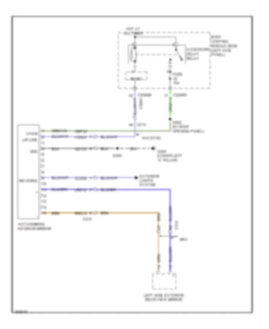 https://portal-diagnostov.com/license.html
Automotive Electricians Portal FZCO
Automotive Electricians Portal FZCO
https://portal-diagnostov.com/license.html
https://portal-diagnostov.com/license.html
Automotive Electricians Portal FZCO
Automotive Electricians Portal FZCOList of elements for Electrochromic Mirror Wiring Diagram for Ford Edge Limited 2013:
- Accessory delay relay
- Auto-dimming interior mirror
- Body control module (bcm) (left kick panel)
- C210
- C213
- C2280b vdn01
- C2280d
- C510
- Cbp32
- Cls28
- Exterior lights system
- Fuse 15a
- G200 (lower left "a" pillar)
- Gd133
- Gnd
- Hot at all times
- Left side exterior rear view mirror
- Lin line
- Lrd12
- Micro
- Mkx
- Reverse
- Rrd12
- S200
- S902 (w/ roof opening panel)
- Vdn01
- Vpwr
- W/o sync
Power Mirrors Wiring Diagram for Ford Edge Limited 2013
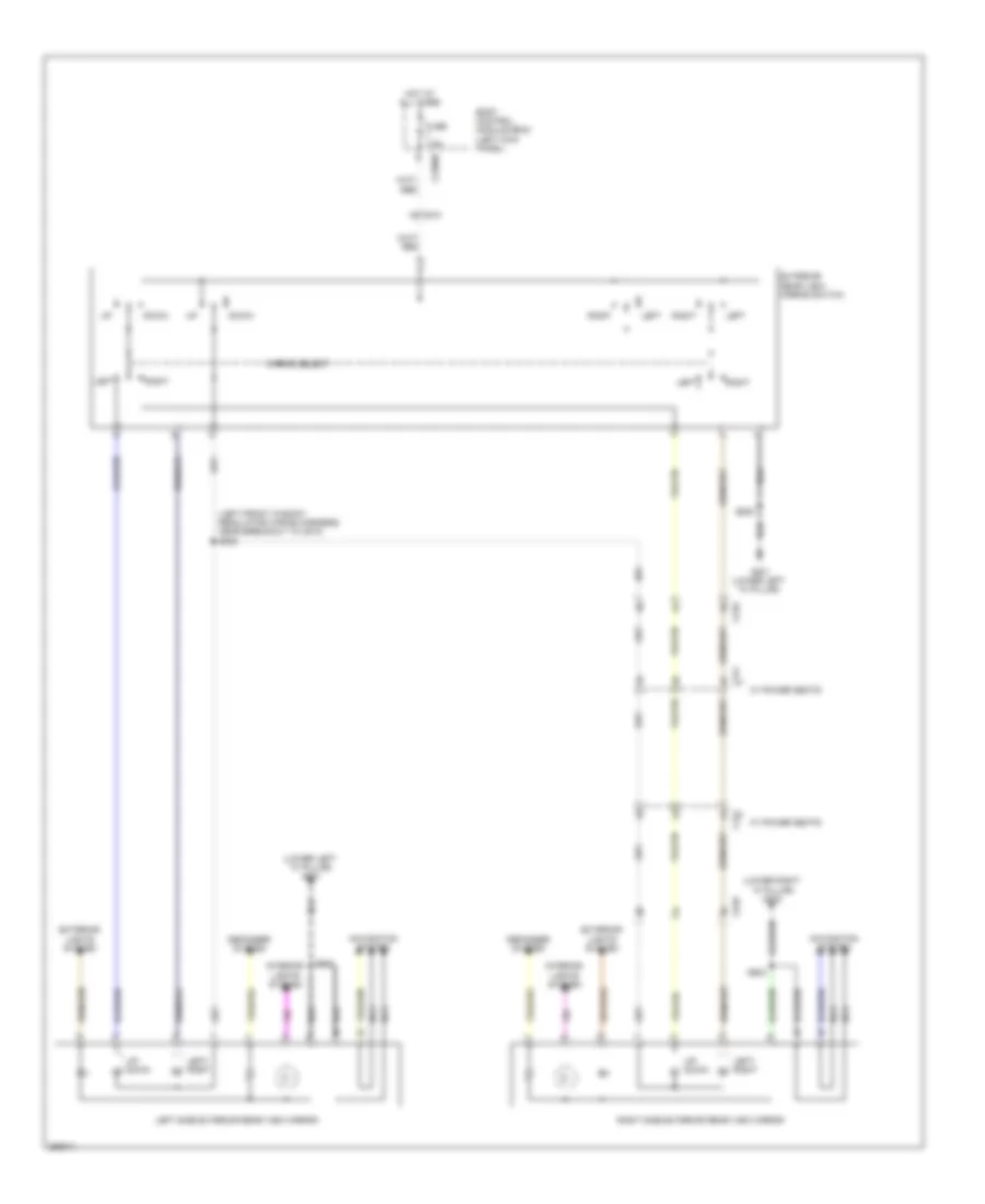 https://portal-diagnostov.com/license.html
Automotive Electricians Portal FZCO
Automotive Electricians Portal FZCO
https://portal-diagnostov.com/license.html
https://portal-diagnostov.com/license.html
Automotive Electricians Portal FZCO
Automotive Electricians Portal FZCOList of elements for Power Mirrors Wiring Diagram for Ford Edge Limited 2013:
- (left front window regulator wiring harness, near breakout to c510) s500
- (lower left "a" pillar) g201
- (lower right "a" pillar) g202
- Body control module (bcm) (left kick panel)
- C2280d
- C311
- C510
- C610
- Defogger system
- Down
- Exterior lights system
- Exterior rear view mirror switch
- Fuse 7.5a
- G201 (lower left "a" pillar)
- Hot at all times
- Interior lights system
- Left
- Left side exterior rear view mirror
- Left/ right
- Left/ right m
- Mirror select
- Navigation system
- Nca
- Right
- Right side exterior rear view mirror
- S502
- S604
- Up/ down
- Up/ down m
- W/ power seats
POWER SEATS
Front Heated Seats Wiring Diagram for Ford Edge Limited 2013
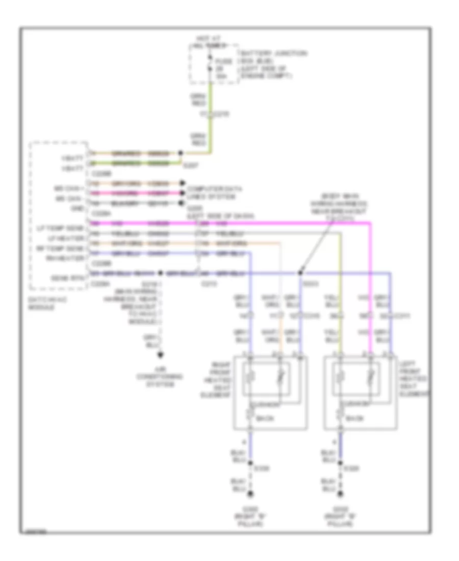 https://portal-diagnostov.com/license.html
Automotive Electricians Portal FZCO
Automotive Electricians Portal FZCO
https://portal-diagnostov.com/license.html
https://portal-diagnostov.com/license.html
Automotive Electricians Portal FZCO
Automotive Electricians Portal FZCOList of elements for Front Heated Seats Wiring Diagram for Ford Edge Limited 2013:
- (body main wiring harness, near breakout to c311)
- Air conditioning system
- Back
- Battery junction box (bjb) (left side of engine compt)
- C213
- C215
- C228a
- C228b
- C311
- C315
- Chs02
- Chs07
- Computer data lines system
- Cushion
- Datc hvac module
- Fuse 30a
- G205 (left side of dash)
- G302 (right "b" pillar)
- Gd115
- Gnd
- Hot at all times
- Left front heated seat element
- Lf heater
- Lf temp sens
- Ms can +
- Ms can -
- Rf temp sens
- Rh heater
- Rh111
- Right front heated seat element
- S207
- S219 (main wiring harness, near breakout to hvac module)
- S320
- S330
- S333
- Sbb28
- Sens rtn
- Vbatt
- Vdb06
- Vdb07
- Vhs26
- Vhs27
Heated Steering Wheel Wiring Diagram for Ford Edge Limited 2013
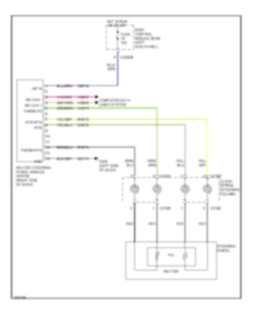 https://portal-diagnostov.com/license.html
Automotive Electricians Portal FZCO
Automotive Electricians Portal FZCO
https://portal-diagnostov.com/license.html
https://portal-diagnostov.com/license.html
Automotive Electricians Portal FZCO
Automotive Electricians Portal FZCOList of elements for Heated Steering Wheel Wiring Diagram for Ford Edge Limited 2013:
- Body control module (bcm) (left kick panel)
- C218a
- C218b
- C218d
- C218e
- C2280b
- Cbp36
- Chs72
- Clock- spring (steering column)
- Computer data lines system
- Fuse 10a
- G205 (left side of dash)
- Gd115
- Gnd
- Heated steering wheel module (hswm) (right side of dash)
- Heater
- Hot in run or start
- Htr
- Htr rtn
- Isp r
- Ms can +
- Ms can -
- Nca
- Pia
- Rhs72
- Rhs73
- Steering wheel
- Therm fd
- Therm rtn
- Vdb06
- Vdb07
- Vhs73
Power Seats Wiring Diagram, 10-Way Driver Seat for Ford Edge Limited 2013
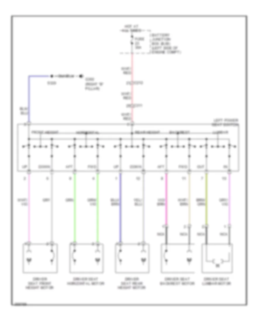 https://portal-diagnostov.com/license.html
Automotive Electricians Portal FZCO
Automotive Electricians Portal FZCO
https://portal-diagnostov.com/license.html
https://portal-diagnostov.com/license.html
Automotive Electricians Portal FZCO
Automotive Electricians Portal FZCOList of elements for Power Seats Wiring Diagram, 10-Way Driver Seat for Ford Edge Limited 2013:
- (right "b" pillar)
- Aft
- Backrest
- Battery junction box (bjb) (left side of engine compt)
- C212
- C311
- Down
- Driver seat backrest motor
- Driver seat front height motor
- Driver seat horizontal motor
- Driver seat lumbar motor
- Driver seat rear height motor
- Front height
- Fuse 30a
- Fwd
- G302
- Horizontal
- Hot at all times
- Left power seat switch
- Lumbar
- Nca
- Out
- Rear height
- S320
Power Seats Wiring Diagram, 10-Way Passenger Seat for Ford Edge Limited 2013
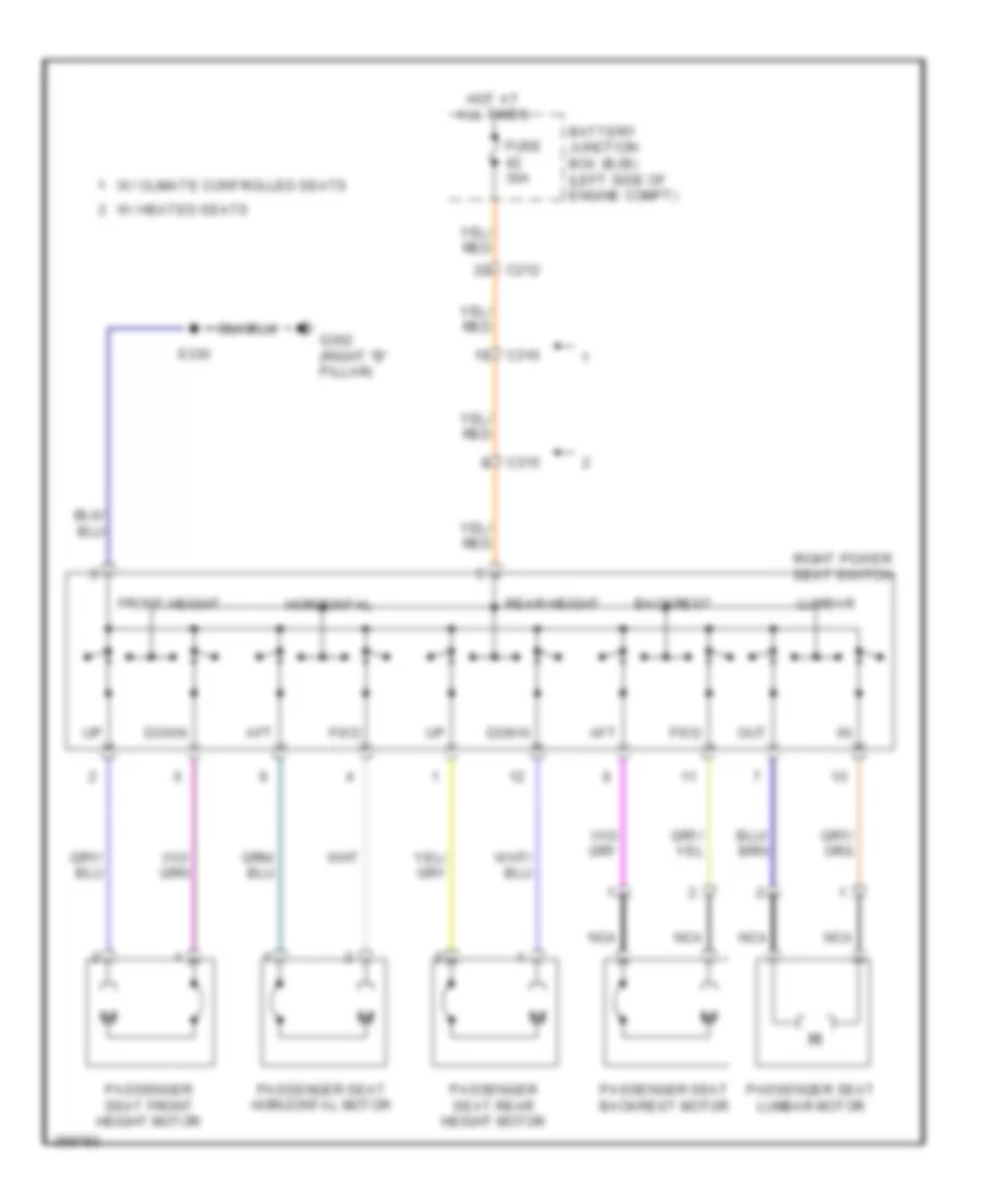 https://portal-diagnostov.com/license.html
Automotive Electricians Portal FZCO
Automotive Electricians Portal FZCO
https://portal-diagnostov.com/license.html
https://portal-diagnostov.com/license.html
Automotive Electricians Portal FZCO
Automotive Electricians Portal FZCOList of elements for Power Seats Wiring Diagram, 10-Way Passenger Seat for Ford Edge Limited 2013:
- Aft
- Backrest
- Battery junction box (bjb) (left side of engine compt)
- C212
- C315
- C316
- Down
- Front height
- Fuse 30a
- Fwd
- G302 (right "b" pillar)
- Horizontal
- Hot at all times
- Lumbar
- Nca
- Out
- Passenger seat backrest motor
- Passenger seat front height motor
- Passenger seat horizontal motor
- Passenger seat lumbar motor
- Passenger seat rear height motor
- Rear height
- Right power seat switch
- S330
- W/ climate controlled seats
- W/ heated seats
Power Seats Wiring Diagram, 6-Way Driver Seat for Ford Edge Limited 2013
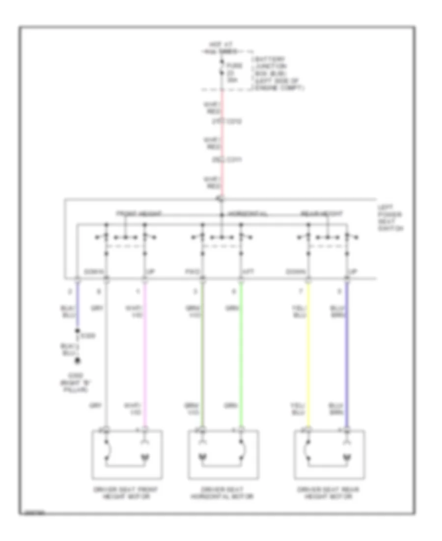 https://portal-diagnostov.com/license.html
Automotive Electricians Portal FZCO
Automotive Electricians Portal FZCO
https://portal-diagnostov.com/license.html
https://portal-diagnostov.com/license.html
Automotive Electricians Portal FZCO
Automotive Electricians Portal FZCOList of elements for Power Seats Wiring Diagram, 6-Way Driver Seat for Ford Edge Limited 2013:
- Aft
- Battery junction box (bjb) (left side of engine compt)
- C212
- C311
- Down
- Driver seat front height motor
- Driver seat horizontal motor
- Driver seat rear height motor
- Front height
- Fuse 30a
- Fwd
- G302 (right "b" pillar)
- Horizontal
- Hot at all times
- Left power seat switch
- Rear height
- S320
Power Seats Wiring Diagram, 6-Way passenger Seat for Ford Edge Limited 2013
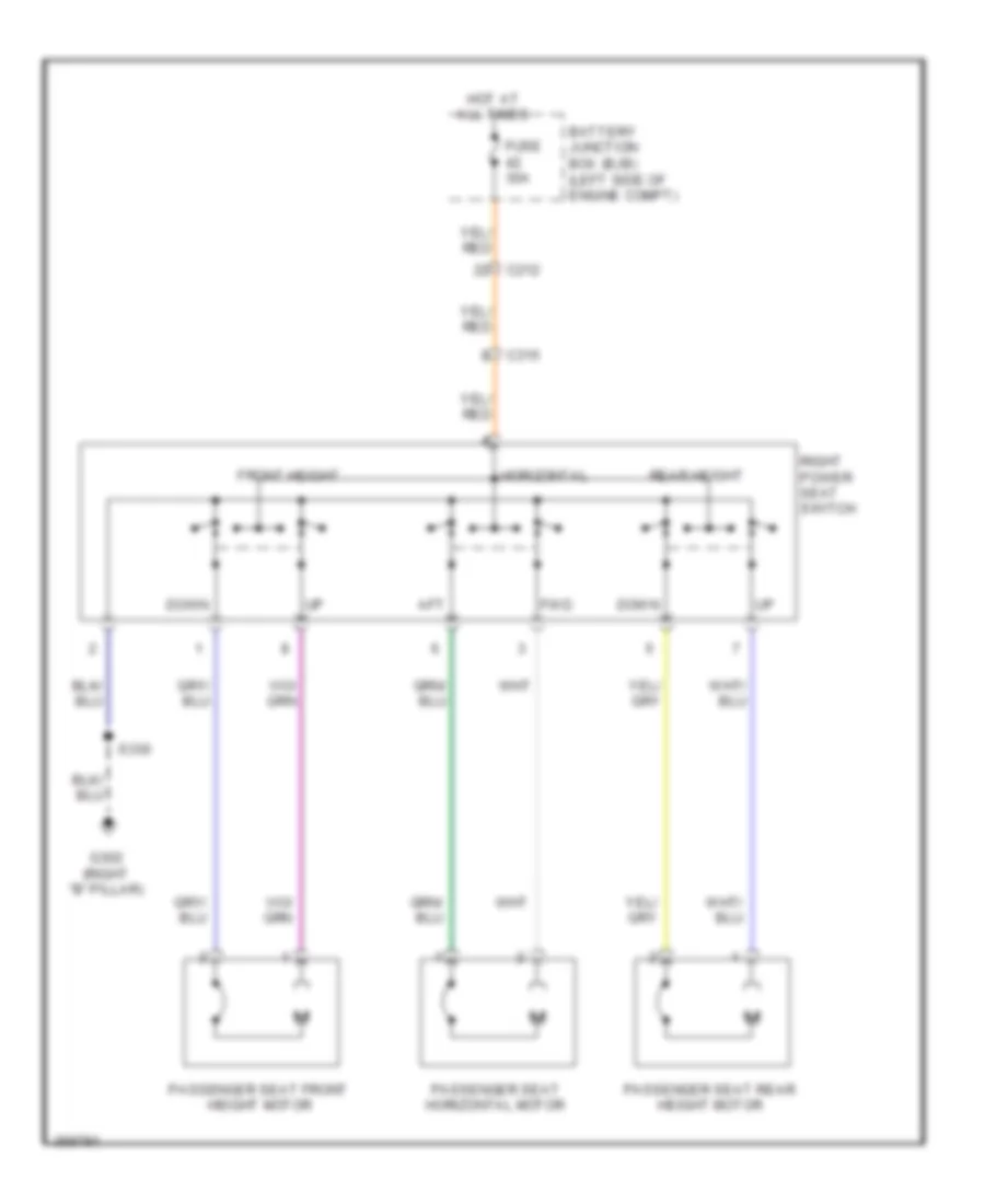 https://portal-diagnostov.com/license.html
Automotive Electricians Portal FZCO
Automotive Electricians Portal FZCO
https://portal-diagnostov.com/license.html
https://portal-diagnostov.com/license.html
Automotive Electricians Portal FZCO
Automotive Electricians Portal FZCOList of elements for Power Seats Wiring Diagram, 6-Way passenger Seat for Ford Edge Limited 2013:
- Aft
- Battery junction box (bjb) (left side of engine compt)
- C212
- C315
- Down
- Front height
- Fuse 30a
- Fwd
- G302 (right "b" pillar)
- Horizontal
- Hot at all times
- Passenger seat front height motor
- Passenger seat horizontal motor
- Passenger seat rear height motor
- Rear height
- Right power seat switch
- S330
Rear Heated Seats Wiring Diagram for Ford Edge Limited 2013
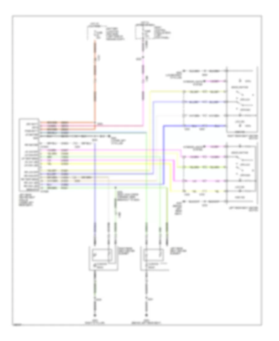 https://portal-diagnostov.com/license.html
Automotive Electricians Portal FZCO
Automotive Electricians Portal FZCO
https://portal-diagnostov.com/license.html
https://portal-diagnostov.com/license.html
Automotive Electricians Portal FZCO
Automotive Electricians Portal FZCOList of elements for Rear Heated Seats Wiring Diagram for Ford Edge Limited 2013:
- Back
- Backlighting
- Battery junction box (bjb) (left side of engine compt)
- Body control module (bcm) (left kick panel)
- C212
- C2280d
- C300
- C3162a
- C3162b
- C700
- C800
- Cbp34
- Chs39
- Chs43
- Chs46
- Chs47
- Chs48
- Chs49
- Chs50
- Chs51
- Chs52
- Chs53
- Cushion
- Drv batt
- Fuse 10a
- Fuse 30a
- G200 (lower left "a" pillar)
- G202 (lower right "a" pillar)
- G300 (behind left rear seat)
- G404 (right "d" pillar)
- Gd133
- Gnd
- High ind
- Hot at all times
- Hot in start or run
- Interior lights system
- Isp r
- Left rear heated seat module (under left rear seat)
- Left rear seat heater element
- Left rear seat heater switch
- Low ind
- Lr heater
- Lr high led
- Lr high/off
- Lr low led
- Lr low/off
- Lr temp sens
- Nca
- Off/high
- Off/low
- Pass batt
- Rhs41
- Right rear seat heater element
- Right rear seat heater switch
- Rr heater
- Rr high led
- Rr high/off
- Rr low led
- Rr low/off
- Rr temp sens
- S200
- S300
- S301
- S302 (body main wiring harness, near breakout to g200)
- S308
- S408
- S700
- S800
- Sbb30
- Sens rtn
- Vhs42
- Vhs45
Second Row Seat Release Wiring Diagram for Ford Edge Limited 2013
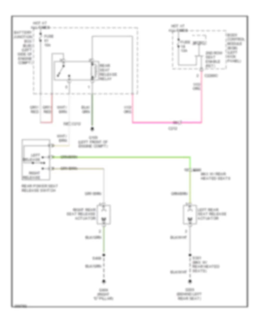 https://portal-diagnostov.com/license.html
Automotive Electricians Portal FZCO
Automotive Electricians Portal FZCO
https://portal-diagnostov.com/license.html
https://portal-diagnostov.com/license.html
Automotive Electricians Portal FZCO
Automotive Electricians Portal FZCOList of elements for Second Row Seat Release Wiring Diagram for Ford Edge Limited 2013:
- 2nd row seat enable (fet)
- Battery junction box (bjb) (left side of engine compt)
- Body control module (bcm) (left kick panel)
- C212
- C2280c
- C300
- Fuse 10a
- G105 (left front of engine compt)
- G300 (behind left rear seat)
- G404 (right "d" pillar)
- Hot at all times
- Left rear seat release actuator
- Left release
- Micro
- Mkx w/ rear heated seats
- Rear power seat release switch
- Rear seat release relay
- Right rear seat release actuator
- Right release
- S301 (mkx w/ rear heated seats)
- S408
POWER TOP/SUNROOF
Power Top/Sunroof Wiring Diagram for Ford Edge Limited 2013
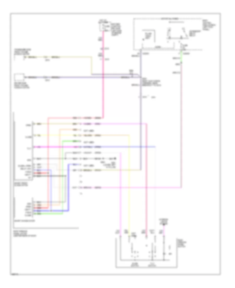 https://portal-diagnostov.com/license.html
Automotive Electricians Portal FZCO
Automotive Electricians Portal FZCO
https://portal-diagnostov.com/license.html
https://portal-diagnostov.com/license.html
Automotive Electricians Portal FZCO
Automotive Electricians Portal FZCOList of elements for Power Top/Sunroof Wiring Diagram for Ford Edge Limited 2013:
- (not used)
- Accessory delay relay
- Battery junction box (bjb) (left side of engine compt)
- Body control module (bcm) (left kick panel)
- C210
- C212
- C2280c
- C2280d
- C510
- C610
- Cbp32
- Close
- Cpr31
- Cpr38
- Cpr39
- Cpr40
- Cpw01
- Delay acc
- Driver side front power window motor
- Fuse 15a
- Fuse 20a
- G201 (lower left "a" pillar)
- Gd133
- Global open
- Gnd
- Hot at all times
- Id1
- Interior lights system
- K bus
- Micro
- Mkx
- Open
- Passenger side front power window motor
- Pulse train (fet)
- Red
- Roof opening panel motor (center rear of roof)
- Roof opening panel switch
- S202 (body main wiring harness, near breakout to c510)
- S902
- S903
- Sbb08
- Slide switch
- Smart front glass motor
- Smart shade motor
- Tilt
- Tilt switch
- Vbatt
POWER WINDOWS
Power Windows Wiring Diagram for Ford Edge Limited 2013
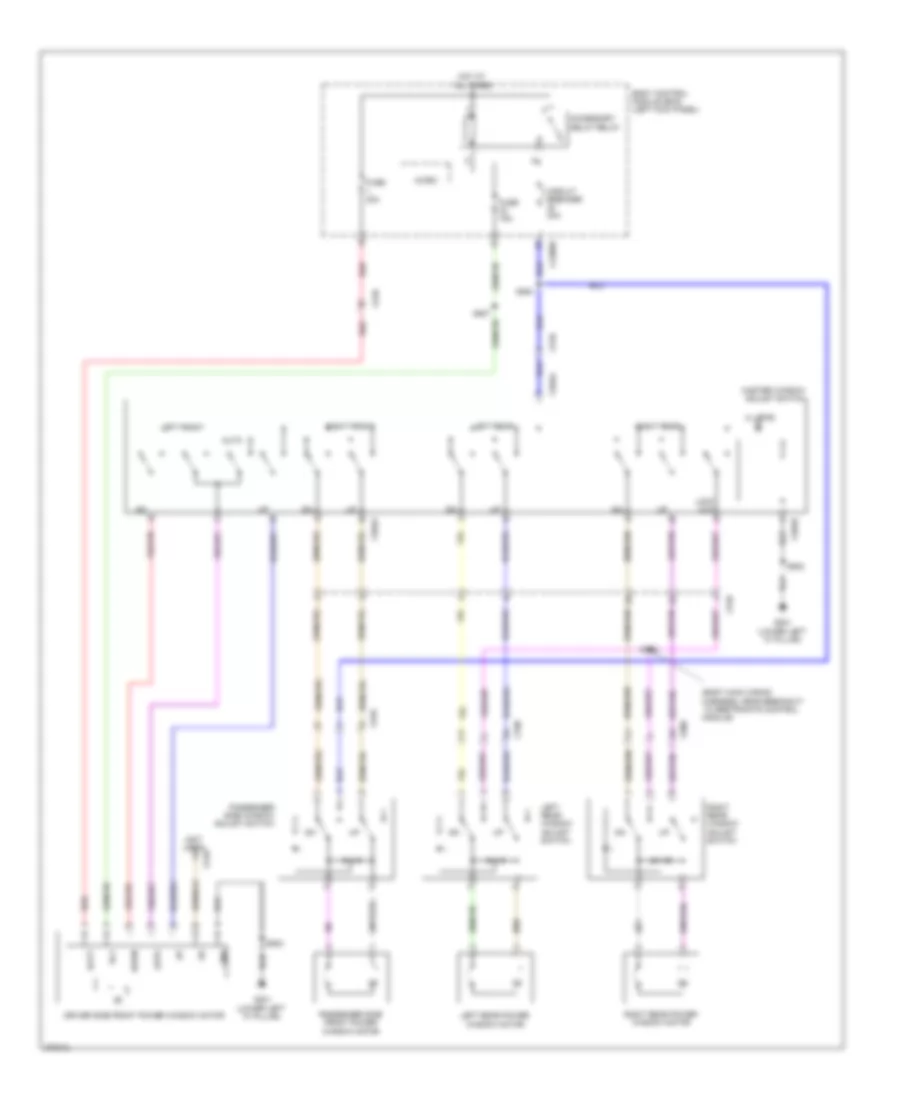 https://portal-diagnostov.com/license.html
Automotive Electricians Portal FZCO
Automotive Electricians Portal FZCO
https://portal-diagnostov.com/license.html
https://portal-diagnostov.com/license.html
Automotive Electricians Portal FZCO
Automotive Electricians Portal FZCOList of elements for Power Windows Wiring Diagram for Ford Edge Limited 2013:
- (4 led's)
- (body main wiring harness, near breakout to restraints control module)
- (not used)
- Accessory delay relay
- Auto
- Batt
- Body control module (bcm) (left kick panel)
- C2280d
- C504a
- C504b
- C510
- C610
- C700
- C800
- Circuit breaker 30a
- Down
- Driver side front power window motor
- Fuse 15a
- Fuse 30a
- G201 (lower left "a" pillar)
- Gnd
- Hot at all times
- Left front
- Left rear
- Left rear power window motor
- Left rear window adjust switch
- Lock out
- Master window adjust switch
- Micro
- Passenger side front power window motor
- Passenger side window adjust switch
- Red
- Right front
- Right rear
- Right rear power window motor
- Right rear window adjust switch
- Rly
- S254
- S326
- S502
- S507
RADIO
Premium Radio Wiring Diagram (1 of 2) for Ford Edge Limited 2013
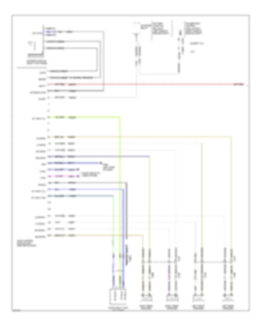 https://portal-diagnostov.com/license.html
Automotive Electricians Portal FZCO
Automotive Electricians Portal FZCO
https://portal-diagnostov.com/license.html
https://portal-diagnostov.com/license.html
Automotive Electricians Portal FZCO
Automotive Electricians Portal FZCOList of elements for Premium Radio Wiring Diagram (1 of 2) for Ford Edge Limited 2013:
- (w/ satellite radio)
- 2.0l
- Am/fm
- Ant pwr
- Antenna module (right kick panel)
- Antenna pwr
- Audio control module (acm) (center of dash)
- Audio input jack (w/o sync)
- Battery junction box (bjc) (left side of engine compt)
- C1381b
- C175b
- C213
- C215
- C219
- C3053
- C510
- C610
- C700
- C800
- Cdc26
- Coaxial cable
- Computer data lines system
- Dme45
- Except 2.0l
- G206 (left side of dash)
- Gd114
- Gnd
- I can+
- I can-
- Left front speaker
- Left rear speaker
- Lf spkr +
- Lf spkr-
- Lr spkr +
- Lr spkr-
- Nca
- Powertrain control module (pcm) (right side of engine compt)
- Rf spkr +
- Rf spkr-
- Right front speaker
- Right rear speaker
- Rme07
- Rme09
- Rme10
- Rme12
- Rme45
- Rr spkr+
- Rr spkr-
- Sbp29
- Sdars
- Shield
- Smcs
- Solid state
- St in 2l +
- St in 2l -
- St in 2r +
- St input 2l+
- St input 2l-
- St input 2r+
- Start
- Starter relay
- Vbatt
- Vdb13
- Vdb14
- Vme07
- Vme09
- Vme10
- Vme12
- Vme43
- Vme45
- Vme46
Premium Radio Wiring Diagram (2 of 2) for Ford Edge Limited 2013
 https://portal-diagnostov.com/license.html
Automotive Electricians Portal FZCO
Automotive Electricians Portal FZCO
https://portal-diagnostov.com/license.html
https://portal-diagnostov.com/license.html
Automotive Electricians Portal FZCO
Automotive Electricians Portal FZCOList of elements for Premium Radio Wiring Diagram (2 of 2) for Ford Edge Limited 2013:
- A/d1
- A/d2
- A/d3
- A/d4
- Body control module (bcm) (left kick panel)
- C218b
- C218c
- C2280a
- C2414a
- C2414d
- Clockspring (steering column)
- Cls32
- Computer data lines system
- Cruise control system
- Down
- Exterior lights system
- Front control interface module (fcim) (center of dash)
- Front control/ display interface module (fcdim) (center of dash)
- Fuse 15a
- Fuse 20a
- G205 (left side of dash)
- Gd115
- Gnd
- Haz sw
- Hot at all times
- Hs can+
- Hs can-
- I can +
- I can -
- Instrument cluster system
- Interior lights system
- Left
- Media (w/o sync) ppt (w/ sync)
- Mute (w/o sync) phone (w/ sync)
- Navigation system
- Nca
- Rh sw gnd
- Right
- Right steering wheel switch
- Rmp19
- S222
- S229
- S291 (steering wheel jumper wiring harness)
- S294
- S295 (steering wheel jumper wiring harness)
- S296 (steering wheel jumper wiring harness)
- Sbp23
- Sbp29
- Seek+
- Seek-
- Steering column control module (sccm) (steering column)
- Vbatt
- Vdb04
- Vdb05
- Vdb13
- Vdb14
- Video+
- Video-
- Vmp19
- Vol+
- Vol-
SONY Radio Wiring Diagram (1 of 2) for Ford Edge Limited 2013
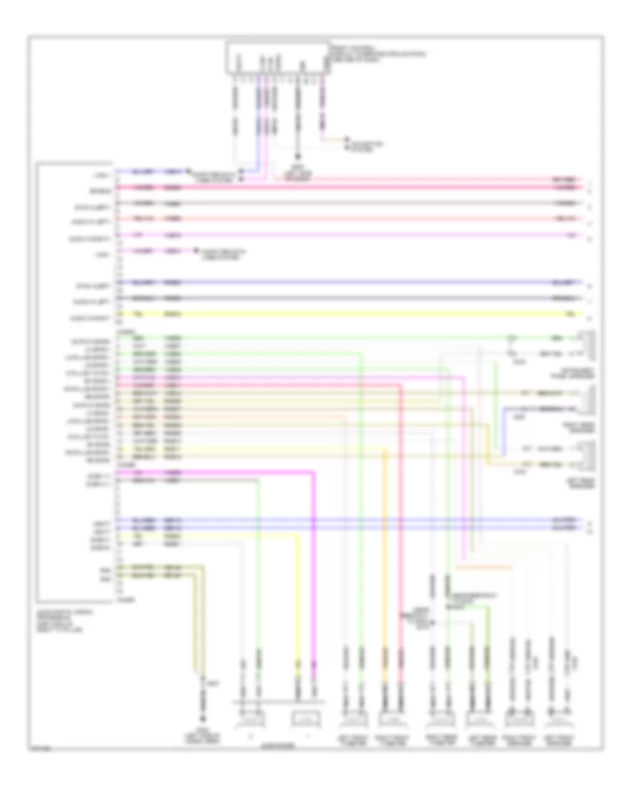 https://portal-diagnostov.com/license.html
Automotive Electricians Portal FZCO
Automotive Electricians Portal FZCO
https://portal-diagnostov.com/license.html
https://portal-diagnostov.com/license.html
Automotive Electricians Portal FZCO
Automotive Electricians Portal FZCOList of elements for SONY Radio Wiring Diagram (1 of 2) for Ford Edge Limited 2013:
- (near breakout to g403) s415
- (near breakout to g403) s416
- Audio digital signal processing (dsp) module (right "c" pillar)
- Audio in left+
- Audio in left-
- Audio in right+
- Audio in right-
- C219
- C4326a
- C4326b
- C4326c
- C510
- C610
- C700
- C800
- Cntr ip spkr+
- Cntr ip spkr-
- Computer data lines system
- D pillar twtr +
- D pillar twtr -
- Enable
- Front control/ display interface module (fcdim) (center of dash)
- G205 (left side of dash)
- G403 (left side of cargo area)
- Gd115
- Gd148
- Gnd
- I can +
- I can -
- Instrument panel speaker
- La-pillar spkr +
- La-pillar spkr -
- Left front speaker
- Left front tweeter
- Left rear speaker
- Left rear tweeter
- Lf spkr +
- Lf spkr -
- Lr spkr +
- Lr spkr -
- Navigation system
- Nca
- Ra-pillar spkr +
- Ra-pillar spkr -
- Rf spkr +
- Rf spkr-
- Right front speaker
- Right front tweeter
- Right rear speaker
- Right rear tweeter
- Rme01
- Rme02
- Rme06
- Rme07
- Rme08
- Rme09
- Rme10
- Rme11
- Rme12
- Rme18
- Rme39
- Rme58
- Rme80
- Rmp19
- Rr spkr+
- Rr spkr-
- S407
- Sbp19
- Sbp29
- Sme23
- Subw 1+
- Subw 2 +
- Subw1-
- Subw2-
- Subwoofer
- Sync alert+
- Sync alert-
- Vbatt
- Vdb13
- Vdb14
- Video+
- Video-
- Vme01
- Vme02
- Vme06
- Vme07
- Vme08
- Vme09
- Vme10
- Vme11
- Vme12
- Vme18
- Vme39
- Vme58
- Vme80
- Vmp19
SONY Radio Wiring Diagram (2 of 2) for Ford Edge Limited 2013
 https://portal-diagnostov.com/license.html
Automotive Electricians Portal FZCO
Automotive Electricians Portal FZCO
https://portal-diagnostov.com/license.html
https://portal-diagnostov.com/license.html
Automotive Electricians Portal FZCO
Automotive Electricians Portal FZCOList of elements for SONY Radio Wiring Diagram (2 of 2) for Ford Edge Limited 2013:
- A/d1
- A/d2
- A/d3
- A/d4
- Accessory protocol interface module (apim) (if equipped) (center of dash)
- Audio control module (acm) (center of dash)
- Body control module (bcm) (left kick panel)
- C214
- C218b
- C218c
- C2280a
- C2280d
- C240a
- C240b
- C2414a
- C2414d
- Clockspring (steering column)
- Cls32
- Computer data lines system
- Cruise control system
- Ctrl mode
- Dme50
- Dme51
- Down
- Enable
- Exterior lights system
- Front control interface module (fcim) (center of dash)
- Fuse 15a
- Fuse 20a
- G205 (left side of dash)
- Gd115
- Gnd
- Haz sw
- Hot at all times
- Hs can+
- Hs can-
- I can+
- I can-
- Instrument cluster system
- Interior lights system
- Left
- Lf spkr+
- Lf spkr-
- Logic gnd
- Media (w/o sync) ppt (w/ sync)
- Mute (w/o sync) phone (w/ sync)
- Nca
- Rf spkr+
- Rf spkr-
- Rh sw gnd
- Right
- Right steering wheel switch
- Rme18
- Rme58
- Rme80
- S229
- S291 (steering wheel jumper wiring harness)
- S294
- S295 (steering wheel jumper wiring harness)
- S296 (steering wheel jumper wiring harness)
- Sbp23
- Sbp29
- Seek+
- Seek-
- Sme23
- Steering column control module (sccm) (steering column)
- Sync alert+
- Sync alert-
- Vbatt
- Vdb04
- Vdb05
- Vdb13
- Vdb14
- Vme18
- Vme58
- Vme80
- Vol+
- Vol-
SYNC Radio Wiring Diagram, with SYNC GEN 1 (1 of 2) for Ford Edge Limited 2013
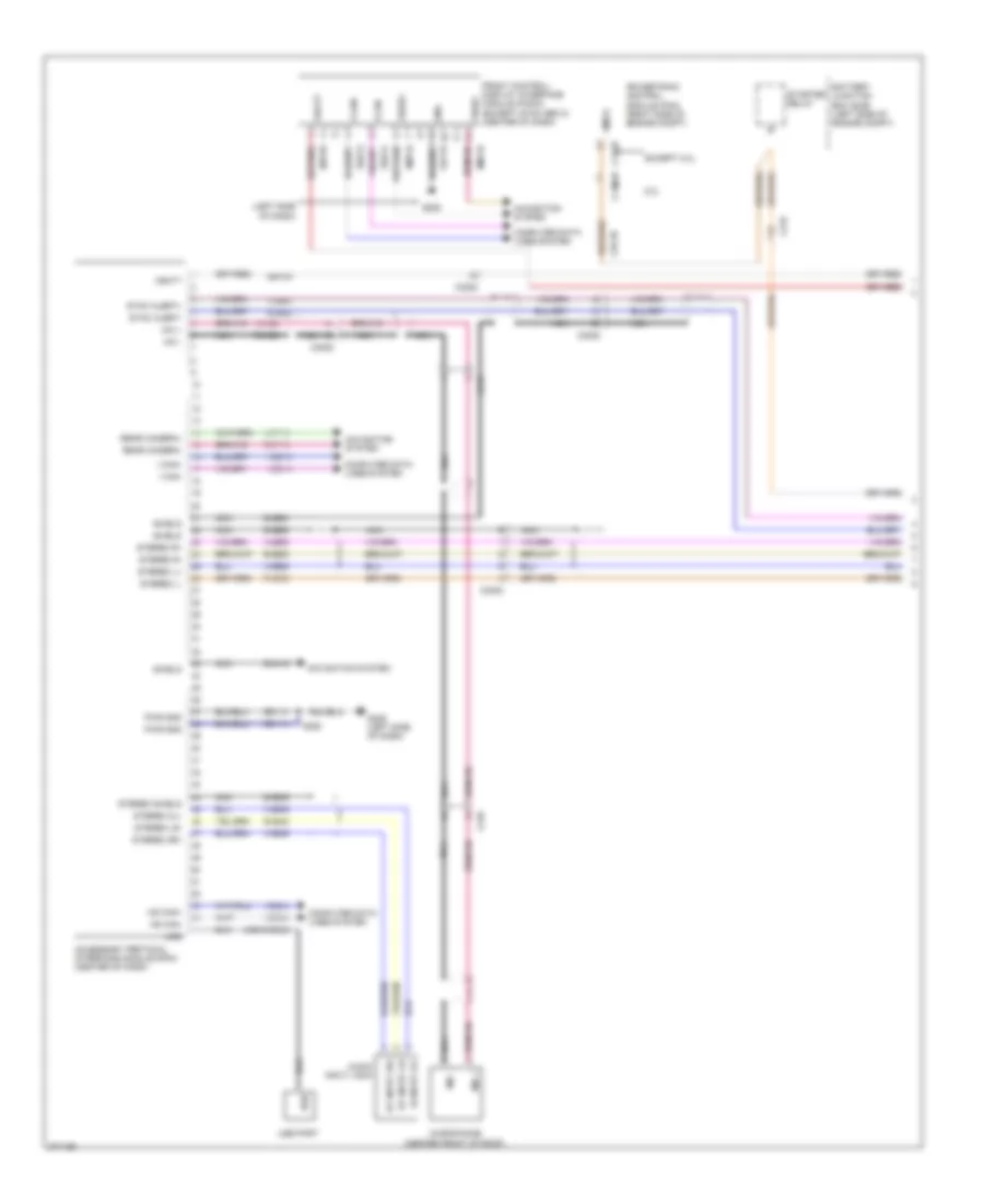 https://portal-diagnostov.com/license.html
Automotive Electricians Portal FZCO
Automotive Electricians Portal FZCO
https://portal-diagnostov.com/license.html
https://portal-diagnostov.com/license.html
Automotive Electricians Portal FZCO
Automotive Electricians Portal FZCOList of elements for SYNC Radio Wiring Diagram, with SYNC GEN 1 (1 of 2) for Ford Edge Limited 2013:
- (left side of dash)
- 2.0l
- Accessory protocol interface module (apim) (center of dash)
- Audio input jack
- Battery junction box (bjb) (left side of engine compt)
- C1381b
- C175b
- C210
- C213
- C215
- C3053
- Cdc26
- Computer data lines system
- Dme45
- Dme52
- Dme80
- Dmn19
- Except 2.0l
- Front control/ display interface module (fcdim) (except sync gen 2) (center of dash)
- G205
- G206 (left side of dash)
- Gd114
- Gd115
- Gnd
- Hs can+
- Hs can-
- I can+
- I can-
- Mic +
- Mic -
- Microphone (center front of roof)
- Navigation system
- Nca
- Powertrain control module (pcm) (right side of engine compt)
- Pwr gnd
- Rear camera+
- Rear camera-
- Rme45
- Rme52
- Rme53
- Rme80
- Rmm23
- Rmp19
- S350
- Sbp29
- Shield
- Si input 2l+
- Smcs
- St input 2r+
- St input lr-
- Starter relay
- Stereo 2l+
- Stereo 2r+
- Stereo l+
- Stereo l-
- Stereo lr-
- Stereo r+
- Stereo r-
- Stereo shield
- Sync alert+
- Sync alert-
- Usb
- Usb cable
- Usb port
- Vbatt
- Vdb04
- Vdb05
- Vdb13
- Vdb14
- Video+
- Video-
- Vme45
- Vme46
- Vme52
- Vme53
- Vme80
- Vmm23
- Vmp19
SYNC Radio Wiring Diagram, with SYNC GEN 1 (2 of 2) for Ford Edge Limited 2013
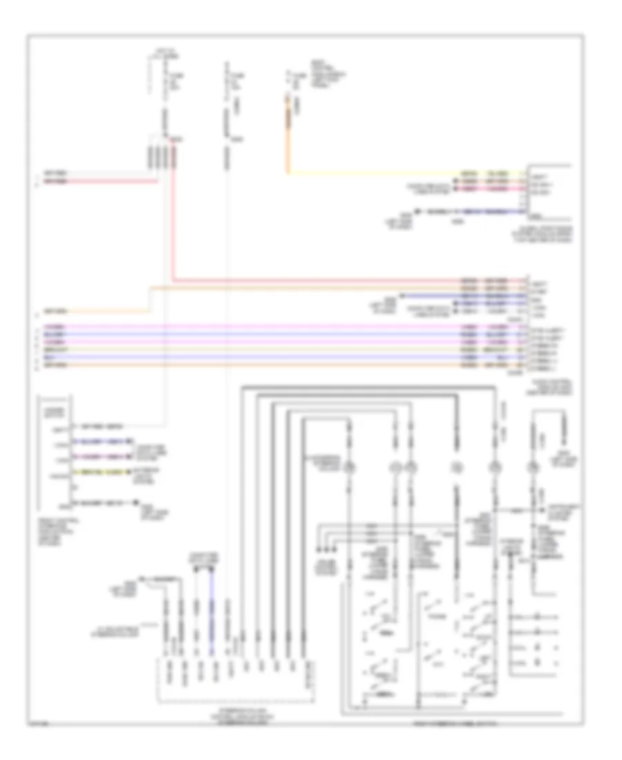 https://portal-diagnostov.com/license.html
Automotive Electricians Portal FZCO
Automotive Electricians Portal FZCO
https://portal-diagnostov.com/license.html
https://portal-diagnostov.com/license.html
Automotive Electricians Portal FZCO
Automotive Electricians Portal FZCOList of elements for SYNC Radio Wiring Diagram, with SYNC GEN 1 (2 of 2) for Ford Edge Limited 2013:
- A/d1
- A/d2
- A/d3
- A/d4
- Audio control module (acm) (center of dash)
- Body control module (bcm) (left kick panel)
- C218a
- C218b
- C218c
- C2280a
- C2280b
- C240a
- C240b
- C2414a
- C2414b
- C2414d
- Cdc26
- Clockspring (steering column)
- Cls32
- Computer data lines system
- Cruise control system
- Down
- Exterior lights system
- Front control interface module (fcim) (center of dash)
- Fuse 15a
- Fuse 20a
- Fuse 5a
- G205 (left side of dash)
- G206 (left side of dash)
- Gd114
- Gd115
- Global positioning system module (gpsm) (top center of dash)
- Gnd
- Haz sw
- Hazard switch
- Hot at all times
- Hs can+
- Hs can-
- I can+
- I can-
- Instrument cluster system
- Interior lights system
- Left
- Logic gnd
- Ms can +
- Ms can -
- Nca
- Phone
- Ptt
- Pwr gnd
- Rh sw gnd
- Right
- Right steering wheel switch
- Rme52
- Rme53
- Rme80
- S213
- S222
- S229
- S268
- S291 (steering wheel jumper wiring harness)
- S294
- S295 (steering wheel jumper wiring harness)
- S296 (steering wheel jumper wiring harness)
- S299 (steering wheel jumper wiring harness)
- Sbp23
- Sbp26
- Sbp29
- Seek+
- Seek-
- Start
- Steering column control module (sccm) (steering column)
- Stereo l+
- Stereo l-
- Stereo r+
- Stereo r-
- Sync alert+
- Sync alert-
- Vbatt
- Vdb04
- Vdb05
- Vdb06
- Vdb07
- Vdb13
- Vdb14
- Vme52
- Vme53
- Vme80
- Vol+
- Vol-
- W/ adjustable steering column
SYNC Radio Wiring Diagram, with SYNC GEN 2 (1 of 2) for Ford Edge Limited 2013
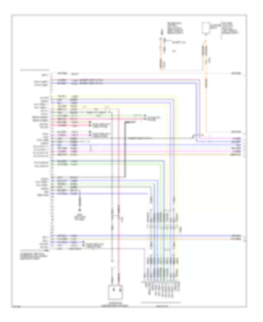 https://portal-diagnostov.com/license.html
Automotive Electricians Portal FZCO
Automotive Electricians Portal FZCO
https://portal-diagnostov.com/license.html
https://portal-diagnostov.com/license.html
Automotive Electricians Portal FZCO
Automotive Electricians Portal FZCOList of elements for SYNC Radio Wiring Diagram, with SYNC GEN 2 (1 of 2) for Ford Edge Limited 2013:
- (except sony & thx)
- 2.0l
- 5v pwr
- Accessory protocol interface module (apim) (center of dash)
- Aux audio r+
- Aux audio r-
- Aux video +
- Aux video -
- Aux video l +
- Aux video l -
- Battery junction box (bjc) (left side of engine compt)
- C1381b
- C175b
- C210
- C213
- C215
- C3053
- Cdc26
- Computer data lines system
- Ctrl mode
- Dme45
- Dme50
- Dme52
- Dme88
- Dmn19
- Except 2.0l
- G205 (left side of dash)
- Gd115
- Gnd
- Hs can+
- Hs can-
- I can+
- I can-
- Lme89
- Media gnd
- Media hub
- Mic +
- Mic -
- Mic in +
- Mic in -
- Microphone (center front of roof)
- Ms can+
- Ms can-
- Navigation system
- Nca
- Powertrain control module (pcm) (right side of engine compt)
- Rear camera+
- Rear camera-
- Rme45
- Rme46
- Rme52
- Rme53
- Rme80
- Rme88
- Rme89
- Rmm23
- Rmp19
- Sbp29
- Sdl-h
- Sdl-l
- Shield
- Smcs
- St output l+
- St output l-
- St output r+
- St output r-
- Starter relay
- Sync alert+
- Sync alert-
- Usb
- Usb cable
- Vbatt
- Vdb04
- Vdb05
- Vdb06
- Vdb07
- Vdb13
- Vdb14
- Vme45
- Vme46
- Vme52
- Vme53
- Vme80
- Vme88
- Vme90
- Vme91
- Vmm23
- Vmp19
SYNC Radio Wiring Diagram, with SYNC GEN 2 (2 of 2) for Ford Edge Limited 2013
 https://portal-diagnostov.com/license.html
Automotive Electricians Portal FZCO
Automotive Electricians Portal FZCO
https://portal-diagnostov.com/license.html
https://portal-diagnostov.com/license.html
Automotive Electricians Portal FZCO
Automotive Electricians Portal FZCOList of elements for SYNC Radio Wiring Diagram, with SYNC GEN 2 (2 of 2) for Ford Edge Limited 2013:
- (center front of roof) antenna module
- (left side of dash)
- (w/ satellite radio)
- A/d1
- A/d2
- A/d3
- A/d4
- Am/fm
- Ant pwr
- Antenna pwr
- Audio control module (acm) (center of dash)
- Body control module (bcm) (left kick panel)
- C218b
- C218c
- C2280a
- C2280b
- C240a
- C240b
- C2414a
- C2414d
- Cdc26
- Clockspring (steering column)
- Cls32
- Coaxial cable
- Computer data lines system
- Cruise control system
- Down
- Exterior lights system
- Front control interface module (fcim) (center of dash)
- Fuse 15a
- Fuse 20a
- Fuse 5a
- G205
- G205 (left side of dash)
- G206 (left side of dash)
- Gd114
- Gd115
- Global positioning system module (gpsm) (top center of dash)
- Gnd
- Haz sw
- Hot at all times
- Hs can+
- Hs can-
- I can+
- I can-
- Instrument cluster system
- Interior lights system
- Left
- Ms can +
- Ms can -
- Nca
- Phone
- Ppt
- Pwr gnd
- Rh sw gnd
- Right
- Right steering wheel switch
- Rme52
- Rme53
- Rme80
- S222
- S229
- S291 (steering wheel jumper wiring harness)
- S294
- S295 (steering wheel jumper wiring harness)
- S296 (steering wheel jumper wiring harness)
- Sbp23
- Sbp26
- Sbp29
- Sdars
- Sdl-h
- Sdl-l
- Seek+
- Seek-
- Solid state
- St input l+
- St input l-
- St input r+
- St input r-
- Start
- Steering column control module (sccm) (steering column)
- Sync alert+
- Sync alert-
- Vbatt
- Vdb04
- Vdb05
- Vdb06
- Vdb07
- Vdb13
- Vdb14
- Vme43
- Vme52
- Vme53
- Vme80
- Vme90
- Vme91
- Vol+
- Vol-
SHIFT INTERLOCK
Shift Interlock Wiring Diagram for Ford Edge Limited 2013
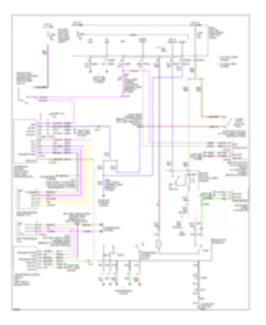 https://portal-diagnostov.com/license.html
Automotive Electricians Portal FZCO
Automotive Electricians Portal FZCO
https://portal-diagnostov.com/license.html
https://portal-diagnostov.com/license.html
Automotive Electricians Portal FZCO
Automotive Electricians Portal FZCOList of elements for Shift Interlock Wiring Diagram for Ford Edge Limited 2013:
- (battery cable wiring harness, near breakout to 6f35 transmission) s183
- (brake pedal support bracket) brake pedal position (bpp) switch
- (lower left "a"pillar) g200
- (main wiring harness, near breakout to passive anti-theft restraint module) s238
- (not used)
- 2.0l
- 6f35 transmission (2.0l)
- 6f50 transmission (except 2.0l)
- Access
- Battery junction box (bjb) (left side of engine compt)
- Body control module (bcm) (left kick panel)
- Bpp
- Brake shift
- Bsi (fet)
- C110
- C1381b
- C1520a
- C175b
- C175t
- C213
- C215
- C2153c
- C2153e
- C2280a
- C2280b
- C2280f
- C3053
- Ccb08
- Cdc35
- Cet40
- Computer data lines system
- Control
- Cpk34
- Except 2.0l
- Fuse 10a
- Fuse 15a
- Hot at all times
- Hs can +
- Hs can -
- Hs can+
- Hs can-
- Ignition switch (w/o intelligent access)
- Instrument panel cluster (ipc)
- Intelligent access) (main wiring harness, near breakout to g205)
- Interlock
- Key in ignition
- Le111
- Lock
- Micro
- Ms can+
- Ms can-
- Nca
- Park
- Park detect
- Powertrain control module (pcm) (right side of engine compt)
- Remote function actuator (rfa) module (w/ intelligent access) (behind glove box)
- Ret24
- S111 (dash panel to headlight junction wiring harness, near breakout to c134)
- S184 (battery cable wiring harness, near breakout to transmission control module)
- S200
- S285 (main wiring harness, near breakout to g205)
- Sstd
- Sstu
- Start
- Start/ stop 1
- Start/ stop 1 (active high)
- Start/stop
- Start/stop switch (w/ intelligent access) (center of dash)
- Starting/ charging system
- Switch
- Tr 1
- Tr 2
- Tr 3
- Tr 4
- Tr gnd
- Tr-p
- Transmission
- Transmission control module (2.0l) (left side of engine compt)
- Transmission system
- Transmissions system
- Trs
- Trsw-pin
- Trsw-pn
- Tss/oss/tr gnd
- Tss/oss/trvpwr
- Vdb04
- Vdb05
- Vdb06
- Vdb07
- Vet29
- Vet30
- Vet31
- Vet32
- W/ intelligent
- W/o intelligent
STARTING/CHARGING
Charging Wiring Diagram for Ford Edge Limited 2013
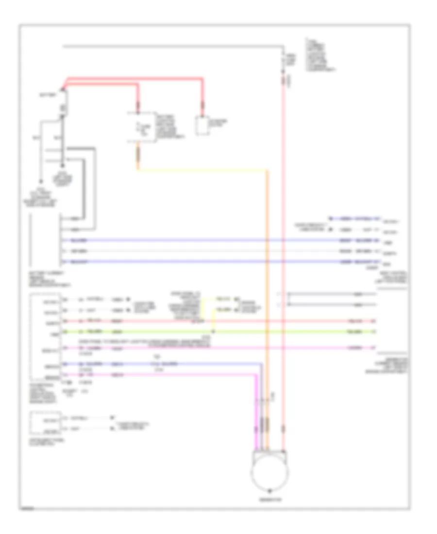 https://portal-diagnostov.com/license.html
Automotive Electricians Portal FZCO
Automotive Electricians Portal FZCO
https://portal-diagnostov.com/license.html
https://portal-diagnostov.com/license.html
Automotive Electricians Portal FZCO
Automotive Electricians Portal FZCOList of elements for Charging Wiring Diagram for Ford Edge Limited 2013:
- (dash panel to headlight junction wiring harness, near breakout to anti-theft hood switch) s119
- 2.0l
- Battery
- Battery current sensor (left rear of engine compartment)
- Battery junction box (bjb) (left side of engine compartment)
- Bcs
- Bcs2 alt
- Body control module (bcm) (left kick panel)
- C110
- C1381b
- C1381e
- C140
- C1617a
- C175b
- C2280f
- Cdc10
- Cdc15
- Computer data lines system
- Controls system
- Engine
- Except 2.0l
- Fuse 10a
- G100 (left side of engine compt)
- G101 (2.0l: front of engine) (except 2.0l: left side of engine)
- Gencom
- Generator
- Generator current sensor (left side of engine compartment)
- Genmon
- High current battery junction box (bjb) (left side of engine compartment)
- Hs can +
- Hs can -
- Instrument panel cluster (ipc)
- Ldc59
- Le424
- Mega fuse 200a
- Nca
- Powertrain control module (pcm) (right side of engine compt)
- Rdc59
- Re407
- Red
- S122 (dash panel to headlight junction wiring harness, near breakout to powertrain control module)
- Sdc57
- Sigrtn
- Starter motor
- Vdb04
- Vdb05
- Vdc61
- Vref
Starting Wiring Diagram for Ford Edge Limited 2013
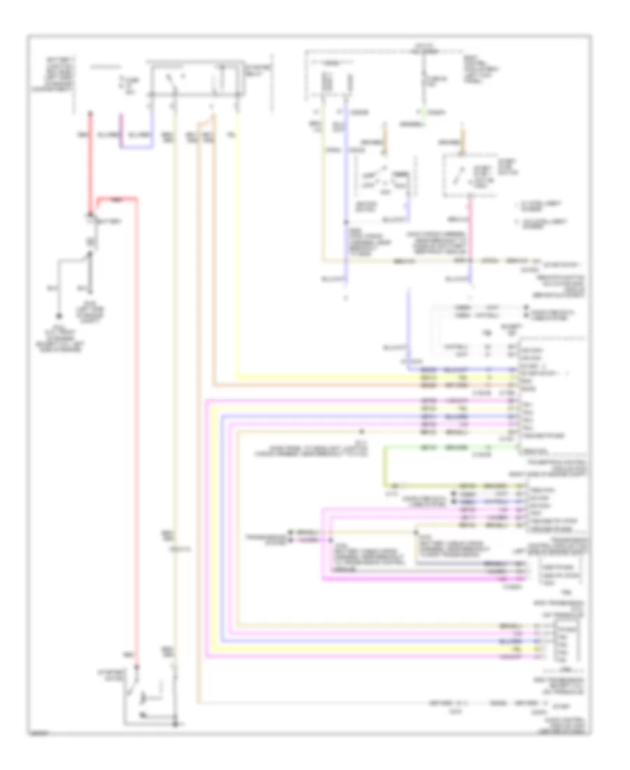 https://portal-diagnostov.com/license.html
Automotive Electricians Portal FZCO
Automotive Electricians Portal FZCO
https://portal-diagnostov.com/license.html
https://portal-diagnostov.com/license.html
Automotive Electricians Portal FZCO
Automotive Electricians Portal FZCOList of elements for Starting Wiring Diagram for Ford Edge Limited 2013:
- (battery cable wiring harness, near breakout to transmission control module)
- (main wiring harness, near breakout to passive anti-theft restraint module)
- 2.0l
- 6f35 transmission (2.0l) (on transaxle)
- 6f50 transmission (except 2.0l) (on transaxle)
- Acc
- Audio control module (acm) (center of dash)
- Battery
- Battery junction box (bjb) (left side of engine compartment)
- Body control module (bcm) (left kick panel)
- C110
- C1381b
- C1520a
- C175b
- C175t
- C215
- C2153c
- C2280a
- C2280b
- C240a
- Cdc12
- Cdc26
- Cdc35
- Cet40
- Computer data lines system
- Cpk34
- Except 2.0l
- Fuse 28 15a
- Fuse 30a
- G100 (left side of engine compt)
- G101 (2.0l: front of engine) (except 2.0l: left side of engine)
- Hot at all times
- Hs can -
- Hs can+
- Hs can-
- Ignition switch
- Le111
- Lock
- Micro
- Off
- Oss/tr gnd
- Oss/tr vpwr
- Powertrain control module (pcm) (right side of engine compt)
- Red
- Remote function actuator (raf) module (behind glove box)
- Ret24
- Run
- S111 (dash panel to headlight junction wiring harness, near breakout to c134)
- S183 (battery cable wiring harness, near breakout to 6f35 transmission)
- S184
- S238
- S285 (main wiring harness, near breakout to g205)
- Smc
- Smcs
- Start
- Start/ stop 1 (active high)
- Start/ stop switch
- Start/stop 1
- Starter motor
- Starter relay
- Stop 1 start/
- Tr gnd
- Tr-1
- Tr-2
- Tr-3
- Tr-4
- Tr-p
- Tr1
- Tr2
- Tr3
- Tr4
- Transmission control module (tcm) (left side of engine compt)
- Transmissions system
- Trs
- Trsw-pin
- Tss/oss/tr gnd
- Tss/oss/tr vpwr
- Vdb04
- Vdb05
- Vet29
- Vet30
- Vet31
- Vet32
- W/ intelligent access
- W/o intelligent access
SUPPLEMENTAL RESTRAINTS
Supplemental Restraints Wiring Diagram (1 of 2) for Ford Edge Limited 2013
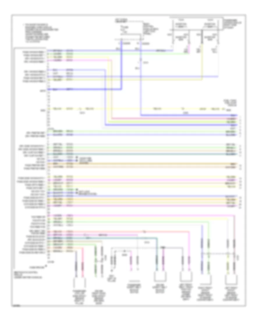 https://portal-diagnostov.com/license.html
Automotive Electricians Portal FZCO
Automotive Electricians Portal FZCO
https://portal-diagnostov.com/license.html
https://portal-diagnostov.com/license.html
Automotive Electricians Portal FZCO
Automotive Electricians Portal FZCOList of elements for Supplemental Restraints Wiring Diagram (1 of 2) for Ford Edge Limited 2013:
- (fuel tank) fuel pump module
- Anti-lock brakes system
- Body control module (bcm) (left kick panel)
- C212
- C213
- C2280b
- C2280d
- C310a
- C310b
- C312
- C314
- C405
- C510
- Case ground
- Cbp41
- Computer data lines system
- Cr101
- Cr102
- Cr103
- Cr104
- Cr105
- Cr106
- Cr109
- Cr111
- Cr120
- Cr122
- Cr167
- Cr201
- Cr203
- Driver front door side impact sensor (driver's door)
- Driver safety belt buckle switch
- Drv air bag feed 1
- Drv air bag feed 2
- Drv air bag rtn 1
- Drv air bag rtn 2
- Drv buckle sw
- Drv curtain feed 1
- Drv curtain ret 1
- Drv preten feed
- Drv preten ret
- Drv seat trk
- Drv side air bag feed 1
- Drv side air bag rtn 1
- Dvr side sn feed 1
- Dvr side sn feed 2
- Dvr side sn rtn 1
- Dvr side sn rtn 2
- Ens
- Fcs feed dr
- Fcs feed pas
- Fcs rtn dr
- Fcs rtn pas
- Fuse 7.5a
- G301 (left "b" pillar)
- Hot in run or start
- Hs can yaw+
- Hs can yaw-
- Hs can+
- Hs can-
- Isp-r
- Left front impact sensor (left front of engine compartment)
- Left front seat track position sensor (under driver's seat)
- Nca
- Pass air bag feed 1
- Pass air bag feed 2
- Pass air bag ret 1
- Pass air bag ret 2
- Pass buckle sw
- Pass crtn feed 1
- Pass crtn ret 1
- Pass preten feed
- Pass preten ret
- Pass side air bag feed 1
- Pass side air bag rtn 1
- Pass side sn feed 1
- Pass side sn feed 2
- Pass side sn return 2
- Pass side sn rtn 1
- Passenger air bag module (right side of dash)
- Passenger c-pillar side impact sensor (right "c" pillar)
- Passenger safety belt buckle switch
- Pin shorting bar is engaged when module connector is disconnected from harness. (shorting bars are connected between the following pins: 1-2, 3-4 c310a)
- Pos sn feed
- Restraints control module (under center console)
- Right front impact sensor (right front of engine compartment)
- Rr101
- Rr102
- Rr103
- Rr104
- Rr105
- Rr106
- Rr109
- Rr111
- Rr120
- Rr122
- Rr129
- Rr130
- Rr131
- Rr132
- Rr133
- Rr134
- S323
- S329
- Shorting bar
- Vca23
- Vca24
- Vdb04
- Vdb05
- Vr213
- Vr214
- Vr215
- Vr217
- Vr218
- Vr219
- Vr220
Supplemental Restraints Wiring Diagram (2 of 2) for Ford Edge Limited 2013
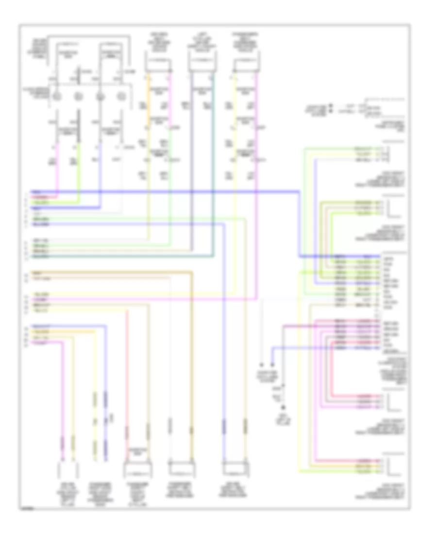 https://portal-diagnostov.com/license.html
Automotive Electricians Portal FZCO
Automotive Electricians Portal FZCO
https://portal-diagnostov.com/license.html
https://portal-diagnostov.com/license.html
Automotive Electricians Portal FZCO
Automotive Electricians Portal FZCOList of elements for Supplemental Restraints Wiring Diagram (2 of 2) for Ford Edge Limited 2013:
- (driver's seat) driver side air bag module
- (left "d" pillar) driver safety canopy module
- (passenger's seat) passenger side air bag module
- C216a
- C216b
- C218a
- C312
- C314
- C327
- C328
- C610
- Cbp41
- Clock spring (steering column)
- Computer data lines system
- Cr140
- Cr141
- Cr153
- Cr154
- Driver air bag module (steering wheel)
- Driver c-pillar side impact sensor (left "c" pillar)
- Driver safety belt retractor pretensioner
- G301 (left "b" pillar)
- Gd143
- Ground
- Hs can+
- Hs can-
- Instrument panel cluster (ipc)
- Isp-r
- Nca
- Occupant classification system module (ocsm) (under front passenger's seat)
- Ocs weight sensor bolt 1 (under right side of front passenger's seat)
- Ocs weight sensor bolt 2 (under right side of front passenger's seat)
- Ocs weight sensor bolt 3 (under left side of front passenger's seat)
- Ocs weight sensor bolt 4 (under left side of front passenger's seat)
- Passenger front door side impact sensor (passenger's door)
- Passenger safety belt retractor pretensioner
- Passenger safety canopy module (right "d" pillar)
- Pwr
- Return
- Rr140
- Rr141
- Rr153
- Rr154
- S329
- Shorting bar
- Sig
- Vdb04
- Vdb05
- Vr211
- Vr212
- Vr226
- Vr227
TRANSMISSION
2.0L
2.0L, A/T Wiring Diagram for Ford Edge Limited 2013
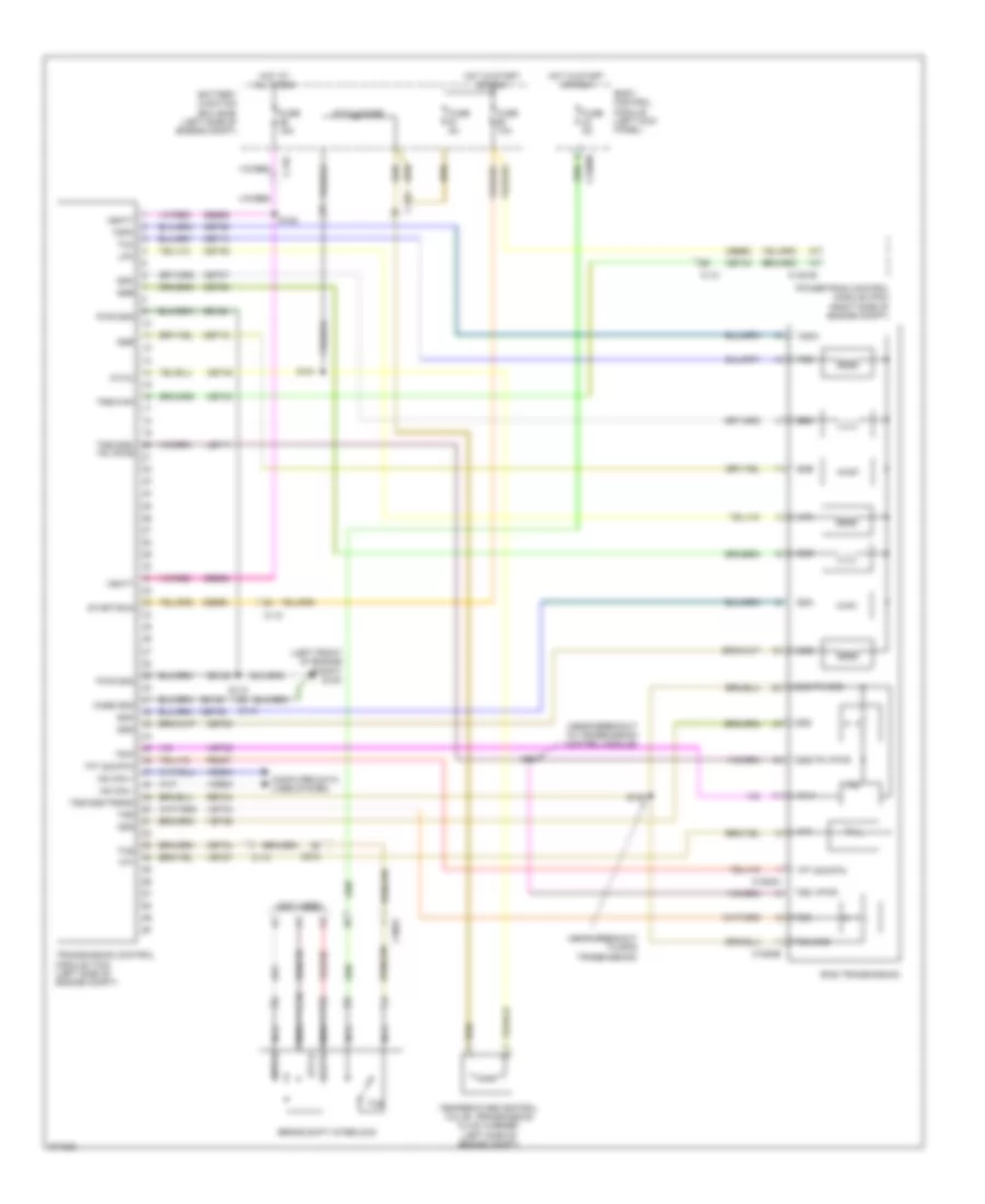 https://portal-diagnostov.com/license.html
Automotive Electricians Portal FZCO
Automotive Electricians Portal FZCO
https://portal-diagnostov.com/license.html
https://portal-diagnostov.com/license.html
Automotive Electricians Portal FZCO
Automotive Electricians Portal FZCOList of elements for 2.0L, A/T Wiring Diagram for Ford Edge Limited 2013:
- (left front of engine compt) g105
- (near breakout to 6f35 transmission)
- (near breakout to transmission control module)
- (not used)
- 6f35 transmission
- Atwu
- Atwu diode
- Battery junction box (bjb) (left side of engine compt)
- Body control module (left kick panel)
- Brake shift interlock
- C110
- C1381b
- C1520a
- C1520b
- C215
- C2280b
- C3053
- Case gnd
- Cbb90
- Cet05
- Cet06
- Cet07
- Cet08
- Cet09
- Cet10
- Cet18
- Cet25
- Cet34
- Cet40
- Cet45
- Computer data lines system
- Fuse 10a
- Fuse 15a
- Fuse 5a
- Gd120
- Hot at all times
- Hot in start or run
- Hs can +
- Hs can -
- Le111
- Lpc
- Nca
- Oss
- Oss/tr gnd
- Oss/tr vpwr
- Powertrain control module (pcm) (right side of engine compt)
- Pwr gnd
- Re407
- Ret24
- S118
- S181
- S182
- S183
- S184
- Sbb56
- Sigrtn
- Ssa
- Ssb
- Ssc
- Ssd
- Sse
- Start/run
- Stt-d
- Stt-u
- Tcc
- Tcs
- Temperature control valve, transmission fluid warmer (left side of engine compt)
- Tft
- Tft sig rtn
- Tr vpwr
- Tr-p
- Transmission control module (tcm) (left side of engine compt)
- Trs
- Trsw-pn
- Tspc
- Tss
- Tss gnd
- Tss vpwr
- Tss/oss/
- Tss/oss/trgnd
- Vbatt
- Vdb04
- Vdb05
- Vet26
- Vet27
- Vet32
- Vet33
3.5L
3.5L, A/T Wiring Diagram (1 of 2) for Ford Edge Limited 2013
 https://portal-diagnostov.com/license.html
Automotive Electricians Portal FZCO
Automotive Electricians Portal FZCO
https://portal-diagnostov.com/license.html
https://portal-diagnostov.com/license.html
Automotive Electricians Portal FZCO
Automotive Electricians Portal FZCOList of elements for 3.5L, A/T Wiring Diagram (1 of 2) for Ford Edge Limited 2013:
- (dash panel to headlight junction wiring harness, near breakout to anti-theft hood switch)
- (under left side of vehicle) evap canister vent solenoid
- 15a
- 6f transmission (on transaxle)
- 7.5a
- App1
- App2
- Apprtn
- Apprtn2
- Appvref
- Appvref2
- Battery junction box (bjb) (left side of engine compt)
- Bpp
- Bps
- C sig trn
- C175b
- C175e
- C175t
- C212
- C215
- Canv
- Cbb69
- Ccb08
- Ce114
- Ce237
- Ce412
- Ce426
- Ces09
- Cet05
- Cet06
- Cet07
- Cet08
- Cet09
- Cet10
- Cet18
- Cet42
- Cet43
- Cet49
- Cht
- Computer data lines system
- E-sigrtn
- Engine controls system
- Etcref
- Etcrtn
- Fuse
- G109 (right front of engine)
- Gd124
- Hot at all times
- Hs can+
- Hs can-
- Kapwr
- Le111
- Le134
- Le136
- Le137
- Lpc
- Oss
- Pcm power relay
- Pcmrc
- Powertrain control module (pcm) (right side of engine compt)
- Pwr gnd
- Re134
- Re136
- Re137
- Re405
- Re406
- Re407
- Ret24
- S111 (dash panel to headlight junction wiring harness, near breakout to c134)
- S117
- S119
- Sbb86
- Ssa
- Ssb
- Ssc
- Ssd
- Sse
- Sstd
- Sstu
- Tacm+
- Tacm-
- Tcc
- Tft
- Tft sig rtn
- Tp1
- Tp2
- Tr gnd
- Tr-1
- Tr-2
- Tr-3
- Tr-4
- Tspc
- Tss
- Tss/oss gnd
- Tss/oss vpwr
- Tss/oss/tr gnd
- Vdb04
- Vdb05
- Ve701
- Ve702
- Ve712
- Ve818
- Ve819
- Vet26
- Vet27
- Vet29
- Vet30
- Vet31
- Vet32
- Vet33
- Vpwr
3.5L, A/T Wiring Diagram (2 of 2) for Ford Edge Limited 2013
 https://portal-diagnostov.com/license.html
Automotive Electricians Portal FZCO
Automotive Electricians Portal FZCO
https://portal-diagnostov.com/license.html
https://portal-diagnostov.com/license.html
Automotive Electricians Portal FZCO
Automotive Electricians Portal FZCOList of elements for 3.5L, A/T Wiring Diagram (2 of 2) for Ford Edge Limited 2013:
- (if equipped) left paddle shifter
- (if equipped) right paddle shifter
- (main wiring harness, near breakout to power point (instrument))
- (not used)
- (steering column) (w/ paddle shift) steering column control module (sccm)
- (w/ paddle shift) s241
- 10a
- Accelerator pedal position sensor (top of accelerator pedal)
- Battery junction box (bjb) (left side of engine compt)
- Body control module (left kick panel)
- Brake pedal position (bpp) switch (brake pedal support bracket)
- Brake shift interlock
- C192
- C215
- C218b
- C218c
- C2280b
- C2414a
- C2414d
- C3053
- Ccb06
- Cet42
- Cet43
- Clockspring (steering column)
- Cylinder head temperature (cht) sensor (front of right cylinder bank)
- Electronic throttle control (etc) motor (throttle body)
- Engine controls system
- Fuse
- G105 (left front of engine compt)
- G205 (left side of dash)
- Hot at all times
- Interior lights system
- Micro
- Nca
- Re407
- S127 (engine control sensor & fuel charge wiring harness, near breakout to coil on plug 3)
- S239 (w/ paddle shift) (main wiring harness, near breakout to g206)
- S240 (w/ paddle shift) (main wiring harness, near breakout to c215)
- S242 (steering wheel jumper wiring harness)
- S243 nca (steering wheel jumper wiring harness)
- S244
- Sstd
- Sstu
- Transmission control switch
- W/ paddle shift
- W/ select shift
3.5L, AWD Wiring Diagram for Ford Edge Limited 2013
 https://portal-diagnostov.com/license.html
Automotive Electricians Portal FZCO
Automotive Electricians Portal FZCO
https://portal-diagnostov.com/license.html
https://portal-diagnostov.com/license.html
Automotive Electricians Portal FZCO
Automotive Electricians Portal FZCOList of elements for 3.5L, AWD Wiring Diagram for Ford Edge Limited 2013:
- (right "d" pillar) g404
- Active torque control coupling (atcc) solenoid (under rear of vehicle)
- All wheel drive (awd) relay module (right "c" pillar)
- Awdc
- Awdm
- Battery junction box (bjb) (left side of engine compt)
- C175b
- C212
- C4004
- Cbb70
- Ccf21
- Computer data lines system
- Fuse 10a
- Gd151
- Gnd
- Hot in start or run
- Hs can +
- Hs can -
- Instrument panel cluster (ipc)
- Nca
- Power distribution system
- Powertrain control module (right side of engine compt)
- Rcf21
- S408
- Vcf34
- Vcf35
- Vpwr
3.7L
3.7L, A/T Wiring Diagram (1 of 2) for Ford Edge Limited 2013
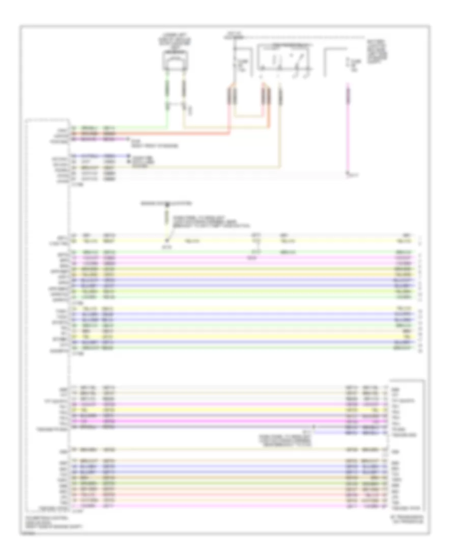 https://portal-diagnostov.com/license.html
Automotive Electricians Portal FZCO
Automotive Electricians Portal FZCO
https://portal-diagnostov.com/license.html
https://portal-diagnostov.com/license.html
Automotive Electricians Portal FZCO
Automotive Electricians Portal FZCOList of elements for 3.7L, A/T Wiring Diagram (1 of 2) for Ford Edge Limited 2013:
- (dash panel to headlight junction wiring harness, near breakout to anti-theft hood switch)
- (under left side of vehicle) evap canister vent solenoid
- 15a
- 6f transmission (on transaxle)
- 7.5a
- App1
- App2
- Apprtn
- Apprtn2
- Appvref
- Appvref2
- Battery junction box (bjb) (left side of engine compt)
- Bpp
- Bps
- C sig trn
- C175b
- C175e
- C175t
- C212
- C215
- Canv
- Cbb69
- Ccb08
- Ce114
- Ce237
- Ce412
- Ce426
- Ces09
- Cet05
- Cet06
- Cet07
- Cet08
- Cet09
- Cet10
- Cet18
- Cet42
- Cet43
- Cet49
- Cht
- Computer data lines system
- E-sigrtn
- Engine controls system
- Etcref
- Etcrtn
- Fuse
- G109 (right front of engine)
- Gd124
- Hot at all times
- Hs can+
- Hs can-
- Kapwr
- Le111
- Le134
- Le136
- Le137
- Lpc
- Oss
- Pcm power relay
- Pcmrc
- Powertrain control module (pcm) (right side of engine compt)
- Pwr gnd
- Re134
- Re136
- Re137
- Re405
- Re406
- Re407
- Ret24
- S111 (dash panel to headlight junction wiring harness, near breakout to c134)
- S117
- S119
- Sbb86
- Ssa
- Ssb
- Ssc
- Ssd
- Sse
- Sstd
- Sstu
- Tacm+
- Tacm-
- Tcc
- Tft
- Tft sig rtn
- Tp1
- Tp2
- Tr gnd
- Tr-1
- Tr-2
- Tr-3
- Tr-4
- Tspc
- Tss
- Tss/oss gnd
- Tss/oss vpwr
- Tss/oss/tr gnd
- Vdb04
- Vdb05
- Ve701
- Ve702
- Ve712
- Ve818
- Ve819
- Vet26
- Vet27
- Vet29
- Vet30
- Vet31
- Vet32
- Vet33
- Vpwr
3.7L, A/T Wiring Diagram (2 of 2) for Ford Edge Limited 2013
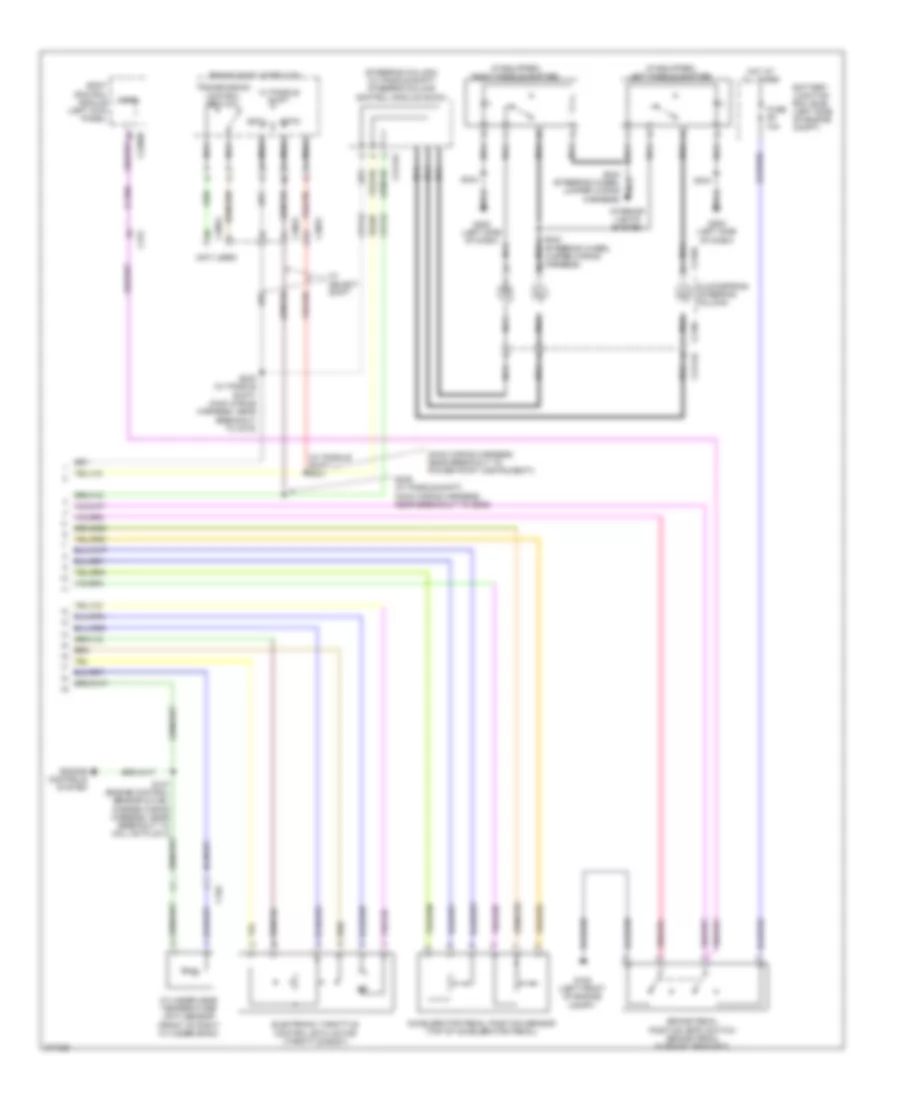 https://portal-diagnostov.com/license.html
Automotive Electricians Portal FZCO
Automotive Electricians Portal FZCO
https://portal-diagnostov.com/license.html
https://portal-diagnostov.com/license.html
Automotive Electricians Portal FZCO
Automotive Electricians Portal FZCOList of elements for 3.7L, A/T Wiring Diagram (2 of 2) for Ford Edge Limited 2013:
- (if equipped) left paddle shifter
- (if equipped) right paddle shifter
- (main wiring harness, near breakout to power point (instrument))
- (not used)
- (steering column) (w/ paddle shift) steering column control module (sccm)
- (w/ paddle shift) s241
- 10a
- Accelerator pedal position sensor (top of accelerator pedal)
- Battery junction box (bjb) (left side of engine compt)
- Body control module (left kick panel)
- Brake pedal position (bpp) switch (brake pedal support bracket)
- Brake shift interlock
- C192
- C215
- C218b
- C218c
- C2280b
- C2414a
- C2414d
- C3053
- Ccb06
- Cet42
- Cet43
- Clockspring (steering column)
- Cylinder head temperature (cht) sensor (front of right cylinder bank)
- Electronic throttle control (etc) motor (throttle body)
- Engine controls system
- Fuse
- G105 (left front of engine compt)
- G205 (left side of dash)
- Hot at all times
- Interior lights system
- Micro
- Nca
- Re407
- S127 (engine control sensor & fuel charge wiring harness, near breakout to coil on plug 3)
- S239 (w/ paddle shift) (main wiring harness, near breakout to g206)
- S240 (w/ paddle shift) (main wiring harness, near breakout to c215)
- S242 (steering wheel jumper wiring harness)
- S243 nca (steering wheel jumper wiring harness)
- S244
- Sstd
- Sstu
- Transmission control switch
- W/ paddle shift
- W/ select shift
3.7L, AWD Wiring Diagram for Ford Edge Limited 2013
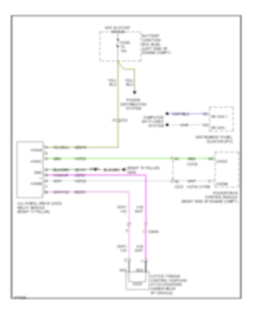 https://portal-diagnostov.com/license.html
Automotive Electricians Portal FZCO
Automotive Electricians Portal FZCO
https://portal-diagnostov.com/license.html
https://portal-diagnostov.com/license.html
Automotive Electricians Portal FZCO
Automotive Electricians Portal FZCOList of elements for 3.7L, AWD Wiring Diagram for Ford Edge Limited 2013:
- (right "d" pillar) g404
- Active torque control coupling (atcc) solenoid (under rear of vehicle)
- All wheel drive (awd) relay module (right "c" pillar)
- Awdc
- Awdm
- Battery junction box (bjb) (left side of engine compt)
- C175b
- C212
- C4004
- Cbb70
- Ccf21
- Computer data lines system
- Fuse 10a
- Gd151
- Gnd
- Hot in start or run
- Hs can +
- Hs can -
- Instrument panel cluster (ipc)
- Nca
- Power distribution system
- Powertrain control module (right side of engine compt)
- Rcf21
- S408
- Vcf34
- Vcf35
- Vpwr
TRUNK, TAILGATE, FUEL DOOR
Liftgate Release Wiring Diagram for Ford Edge Limited 2013
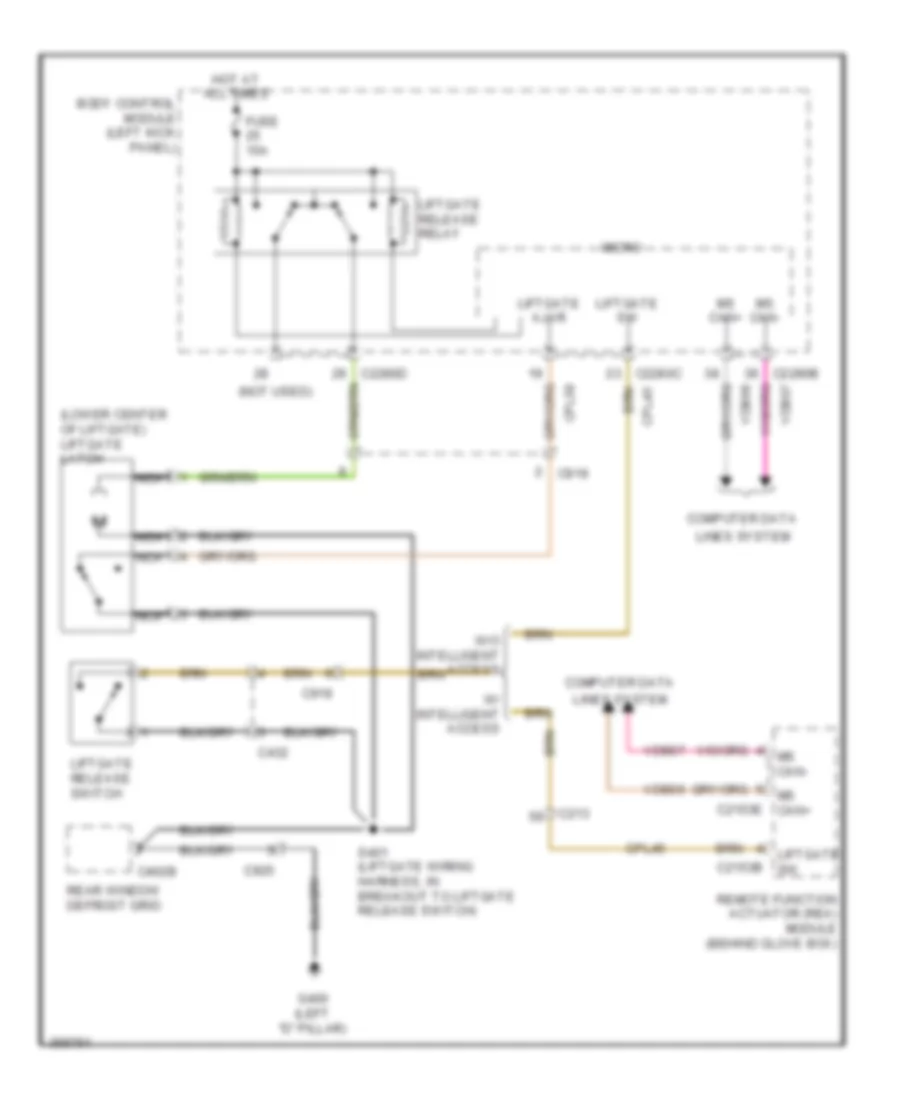 https://portal-diagnostov.com/license.html
Automotive Electricians Portal FZCO
Automotive Electricians Portal FZCO
https://portal-diagnostov.com/license.html
https://portal-diagnostov.com/license.html
Automotive Electricians Portal FZCO
Automotive Electricians Portal FZCOList of elements for Liftgate Release Wiring Diagram for Ford Edge Limited 2013:
- (lower center of liftgate) liftgate latch
- (not used)
- Body control module (left kick panel)
- C213
- C2153b
- C2153e
- C2280b
- C2280c
- C2280d
- C402b
- C432
- C919
- C925
- Computer data
- Cpl45
- Cpl58
- Fuse 15a
- G400 (left "d" pillar)
- Hot at all times
- Liftgate ajar
- Liftgate release relay
- Liftgate release switch
- Liftgate sw
- Lines system
- Micro
- Ms can+
- Ms can-
- Nca
- Rear window defrost grid
- Remote function actuator (rea) module (behind glove box)
- S401 (liftgate wiring harness, in breakout to liftgate release switch)
- Vdb06
- Vdb07
- W/ intelligent access
- W/o intelligent access
Power Liftgate Wiring Diagram for Ford Edge Limited 2013
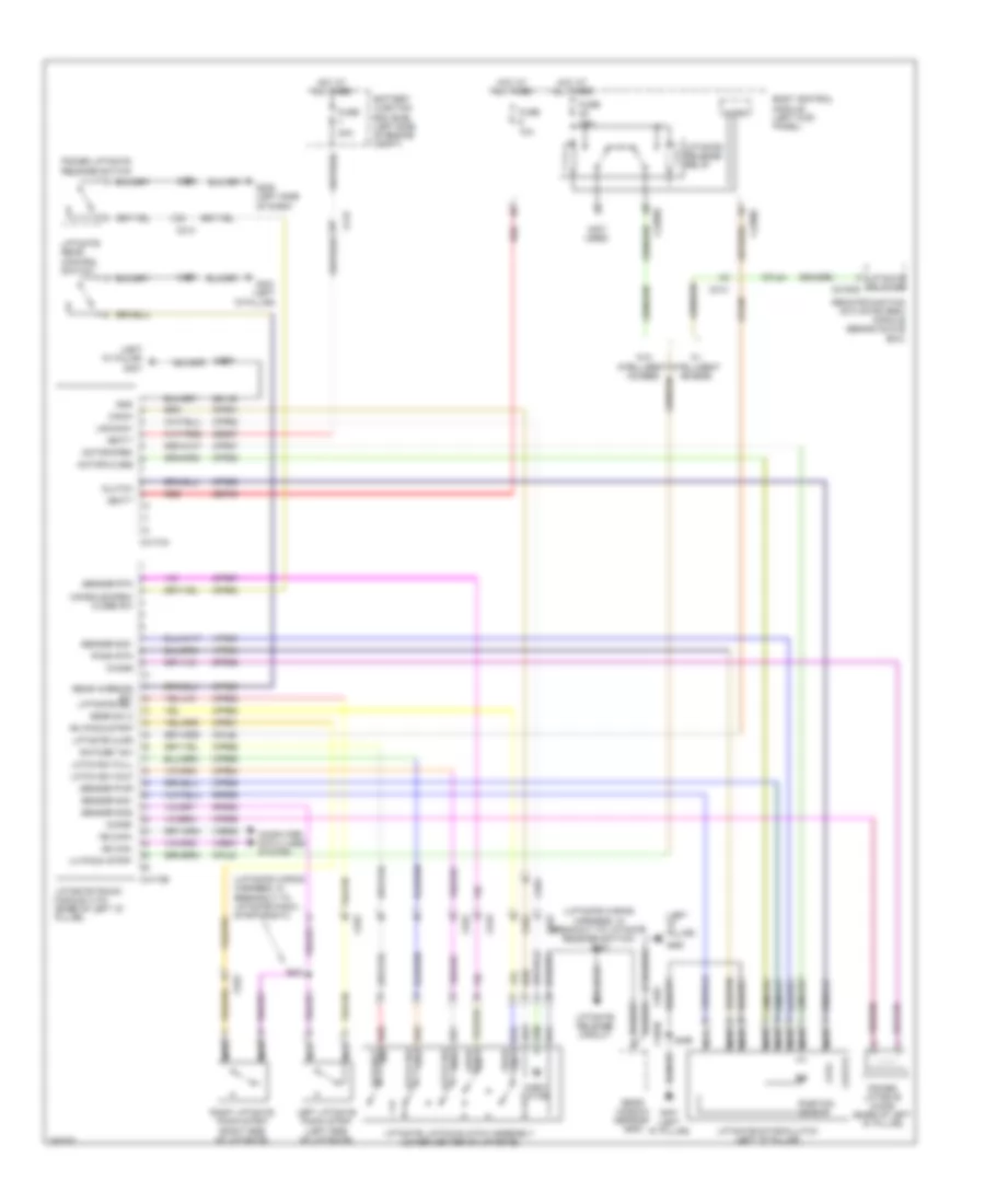 https://portal-diagnostov.com/license.html
Automotive Electricians Portal FZCO
Automotive Electricians Portal FZCO
https://portal-diagnostov.com/license.html
https://portal-diagnostov.com/license.html
Automotive Electricians Portal FZCO
Automotive Electricians Portal FZCOList of elements for Power Liftgate Wiring Diagram for Ford Edge Limited 2013:
- (left "d" pillar)
- (left "d" pillar) g401
- (liftgate wiring harness, in breakout to liftgate pinch strip (right))
- (liftgate wiring harness, in breakout to liftgate release switch) s401
- (not used)
- 10a
- 30a
- Battery junction box (bjb) (left side of engine compt)
- Body control module (left kick panel)
- C212
- C213
- C2280c
- C2280d
- C402b
- C4174a
- C4174b
- C919
- C922
- C925
- Chime+
- Chime-
- Cinch
- Cinch motor
- Clutch
- Computer data lines system
- Console open/ close sw
- Cpl58
- Cpl84
- Cpr51
- Cpr52
- Cpr55
- Cpr56
- Cpr57
- Cpr58
- Cpr61
- Cpr62
- Cpr63
- Cpr64
- Cpr65
- Cpr66
- Cpr67
- Cpr68
- Cpr69
- Cpr89
- Fuse
- Fuse 15a
- G205 (left side of dash)
- G400
- G401 (left "d" pillar)
- Gd149
- Gear sw 2
- Gnd
- Hot at all times
- Latch sw
- Latch sw full
- Latch sw half
- Left liftgate pinch strip (left side of liftgate)
- Lh pinch strip
- Liftgate ajar
- Liftgate latch/unlatch assembly (lower center of liftgate)
- Liftgate motor/clutch (left "d" pillar)
- Liftgate rear control switch
- Liftgate release c2153d
- Liftgate release circuit
- Liftgate release relay
- Liftgate/trunk module (ltm) (base of left "d" pillar)
- Micro
- Motor close
- Motor open
- Ms can+
- Ms can-
- Nca
- Pinch rtn
- Position sensor
- Power liftgate chime (base of left "d" pillar)
- Power liftgate release switch
- Ratchet
- Ratchet sw
- Rear interior sw liftgate rel
- Rear window defrost grid
- Red
- Red sw
- Remote function actuator (rea) module (behind glove box)
- Rh pinch strip
- Right liftgate pinch strip (right side of liftgate)
- Rpr52
- Rpr55
- Rpr56
- S208
- S400
- S409
- Sbb07
- Sbp09
- Sensor pwr
- Sensor rtn
- Sensor sig1
- Sensor sig2
- Uncinch
- Vbatt
- Vdb06
- Vdb07
- Vpr53
- Vpr54
- W/ intelligent access
- W/o intelligent access
WARNING SYSTEMS
Chime Wiring Diagram for Ford Edge Limited 2013
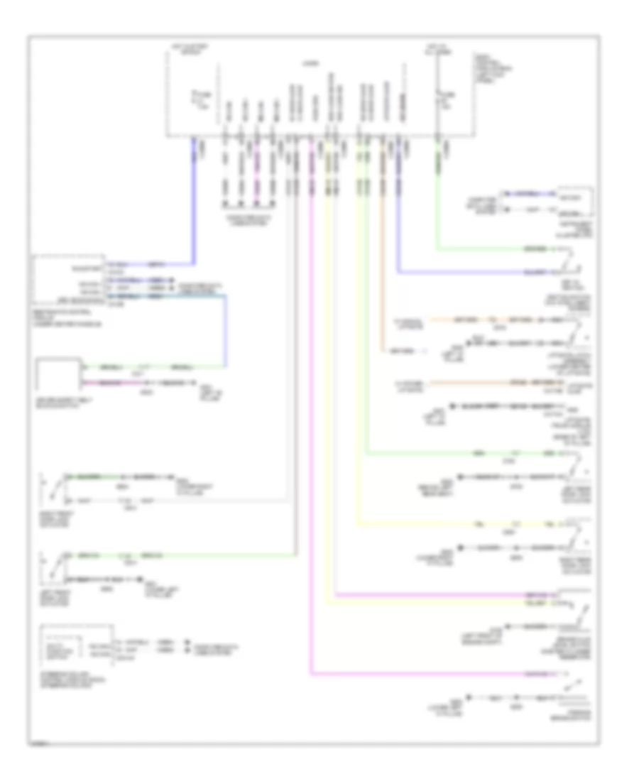 https://portal-diagnostov.com/license.html
Automotive Electricians Portal FZCO
Automotive Electricians Portal FZCO
https://portal-diagnostov.com/license.html
https://portal-diagnostov.com/license.html
Automotive Electricians Portal FZCO
Automotive Electricians Portal FZCOList of elements for Chime Wiring Diagram for Ford Edge Limited 2013:
- Body control module (bcm) (left kick panel)
- Brake fluid level switch (master cylinder reservoir)
- Brk fluid sw
- Brk fluid sw rtn
- C2280a
- C2280b
- C2280c
- C2280f
- C2414a
- C310a
- C310b
- C311
- C4174a
- C4174b
- C510
- C610
- C700
- C800
- C919
- Cbp41
- Cdc30
- Cdc58
- Cmc19
- Cmc25
- Computer data lines system
- Cpl26
- Cpl31
- Cpl36
- Cpl39
- Cpl58
- Cr201
- Driv buckle sw
- Driver safety belt buckle switch
- Fuse 15a
- Fuse 7.5a
- G105 (left front of engine compt)
- G200 (lower left "a" pillar)
- G201 (lower left "a" pillar)
- G202 (lower right "a" pillar)
- G300 (behind left rear seat)
- G301 (left "b" pillar)
- G400 (left "d" pillar)
- G401 (left "d" pillar)
- Gd149
- Gnd
- Hot at all times
- Hot in start or run
- Hs can +
- Hs can -
- Hs can+
- Hs can-
- Ignition switch (w/o intelligent access)
- Instrument panel cluster (ipc)
- Key in ign
- Key in ignition
- Left front door lock actuator
- Left rear door lock actuator
- Lf door ajar
- Liftgate ajar
- Liftgate latch assembly (lower center of liftgate)
- Liftgate/ trunk module (ltm) (base of left "d" pillar)
- Lr door ajar
- Micro
- Ms can +
- Ms can -
- Multi- function switch
- Nca
- Park brk
- Parking brake switch
- Restraints control module (under center console)
- Rf door ajar
- Right front door lock actuator
- Right rear door lock actuator
- Rmc19
- Rr door ajar
- Run/start
- S200
- S323
- S401
- S409
- S502
- S604
- S700
- S800
- Steering column control module (sccm) (steering column)
- Vdb04
- Vdb05
- Vdb06
- Vdb07
- W/ manual liftgate
- W/ power liftgate
Tire Pressure Monitoring Wiring Diagram for Ford Edge Limited 2013
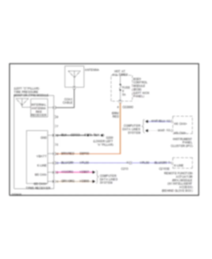 https://portal-diagnostov.com/license.html
Automotive Electricians Portal FZCO
Automotive Electricians Portal FZCO
https://portal-diagnostov.com/license.html
https://portal-diagnostov.com/license.html
Automotive Electricians Portal FZCO
Automotive Electricians Portal FZCOList of elements for Tire Pressure Monitoring Wiring Diagram for Ford Edge Limited 2013:
- (left "c" pillar) tire pressure monitor (tpm) module
- Antenna
- Body control module (bcm) (left kick panel)
- C213
- C2153e
- C2280d
- Coax cable
- Computer data lines system
- Fuse 5a
- G200 (lower left "a" pillar)
- Gd133
- Gnd
- Hot at all times
- Hs can+
- Hs can-
- Instrument panel cluster (ipc)
- Internal antenna rke receiver
- K-line
- Ms can+
- Ms can-
- Remote function actuator (rfa) module (w/ intelligent access) (behind glove box)
- S200
- Sbp06
- Tpms receiver
- Vbatt
- Vdb06
- Vdb07
- Vpl56
WIPER/WASHER
Wiper/Washer Wiring Diagram for Ford Edge Limited 2013
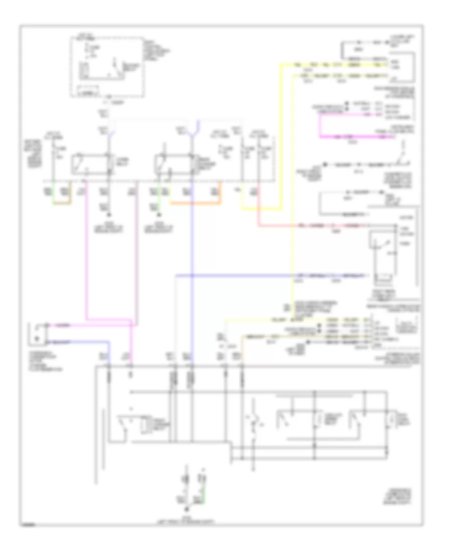 https://portal-diagnostov.com/license.html
Automotive Electricians Portal FZCO
Automotive Electricians Portal FZCO
https://portal-diagnostov.com/license.html
https://portal-diagnostov.com/license.html
Automotive Electricians Portal FZCO
Automotive Electricians Portal FZCOList of elements for Wiper/Washer Wiring Diagram for Ford Edge Limited 2013:
- (lower left "a" pillar) g201
- (main wiring harness, near breakout to instrument panel cluster) s298
- Battery junction box (bjb) (left side of engine compt)
- Body control module (bcm) (left kick panel)
- C210
- C212
- C213
- C215
- C2280f
- C2414a
- C919
- C925
- Cbb45
- Computer data lines system
- Crw15
- Front washer relay
- Frt wiper hi
- Fuse 10a
- Fuse 15a
- Fuse 20a
- Fuse 30a
- Fuse 5a
- G105 (left front of engine compt)
- G107 (right front of engine compt)
- G205 (left side of dash)
- G400 (left "d" pillar)
- Gd115
- Gd133
- Gnd
- Gnd lgc
- Gnd pwr
- Hi input
- High/low speed relay
- Hot at all times
- Hs can+
- Hs can-
- Ign
- Instrument panel cluster (ipc)
- Lin
- Low washer
- Micro
- Motor rr wiper
- Motor+
- Motor-
- Multi- function switch
- Park
- Rain sensor module (top center of windshield)
- Rear washer relay
- Rear window wiper motor (inside liftgate)
- Relay rr wash
- Right rear wiper input relay
- Run/ park relay
- Run/acc relay
- S114
- S401
- S903
- Steering column control module (sccm) (steering column)
- Vdb04
- Vdb05
- Vdn05
- Vign
- Wash
- Washer fluid level switch (washer fluid reservoir)
- Windshield washer pump motor (washer fluid reservoir)
- Windshield wiper motor (left rear of engine compt)
- Wiper relay

 Čeština
 Dansk
Dansk Deutsch
 Ελληνικά
 English
 English
 Español
 Suomi
Suomi Français
 Français
 Hrvatski
 Magyar
 Italiano
 日本語
日本語 한국어
한국어 Nederlands
 Polski
 Português
 Português
 Română
 Русский
 Slovenčina
 Slovenščina
 Svenska
 Türkçe
 中文 (中国)
