AIR CONDITIONING
2.0L
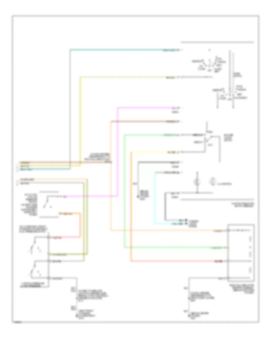
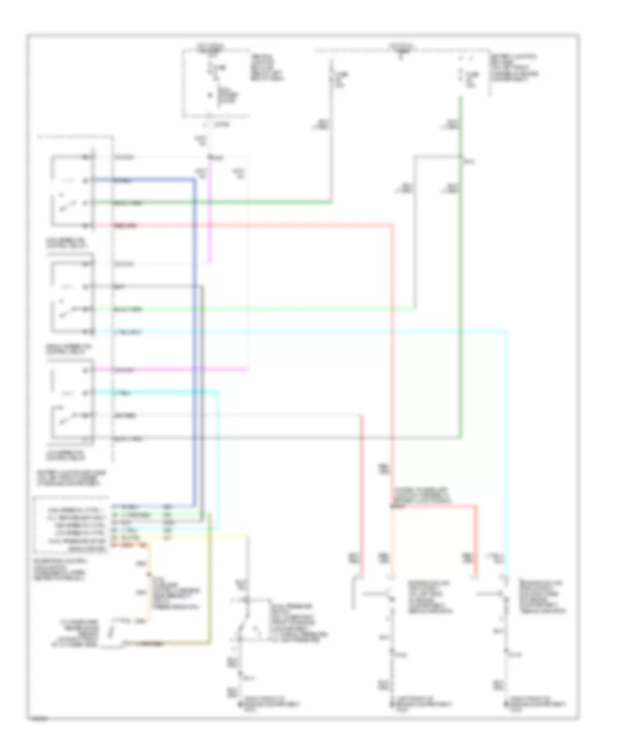
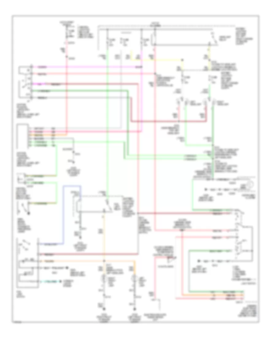
2.0L, Manual A/C Wiring Diagram (1 of 2) for Ford Escape 2003
 https://portal-diagnostov.com/license.html
Automotive Electricians Portal FZCO
Automotive Electricians Portal FZCO
https://portal-diagnostov.com/license.html
https://portal-diagnostov.com/license.html
Automotive Electricians Portal FZCO
Automotive Electricians Portal FZCO
List of elements for 2.0L, Manual A/C Wiring Diagram (1 of 2) for Ford Escape 2003:
- (in dash to headlamp junction harness, in battery junction box) s128
- (in dash to headlamp junction harness, in battery junction box) s132
- (in dash to headlamp junction harness, in battery junction box) s144
- (in dash to headlamp junction harness, near breakout for c134) s116
- (in main harness, near breakout to illumination dimmer) s221
- (left front of engine compartment) g104
- (right front of engine compartment) g102
- (right front of engine compartment) g103
- A/c clutch relay
- A/c clutch rly ctrl
- A/c clutch solenoid
- A/c compressor clutch diode
- Battery junction box (bjb) (on left front corner of engine compartment)
- Blower motor relay (behind lower left center of dash)
- C270b
- C270c
- Central junction box (cjb) (below left end of dash)
- Cyl temp sensor input
- Cylinder head temperature sensor (on right front of cylinder head)
- Dual pressure sw sig
- Engine cooling fan motor 1 (on left side of engine compartment, behind radiator)
- Engine cooling fan motor 2 (on right side of engine compartment, behind radiator)
- Front blower motor (behind right side of dash)
- Fuse 15a
- Fuse 3a
- Fuse 40a
- Fuse 5a
- High speed fan control relay 1
- High speed rly ctrl 1
- Hot at all times
- Hot in run or start
- Junction harness, in battery junction box) s127
- Junction harness, near breakout for anti-theft hood switch) s115
- Low speed fan control relay
- Low speed rly ctrl
- Med speed rly ctrl
- Medium speed fan control relay
- Pcm power diode
- Powertrain control module (pcm) (in recess on upper center of firewall)
- S100 (in engine control harness, near breakout for oil pressure switch)
- Signal return
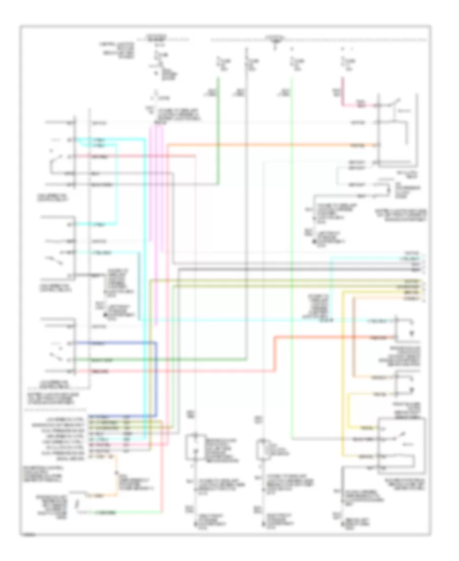
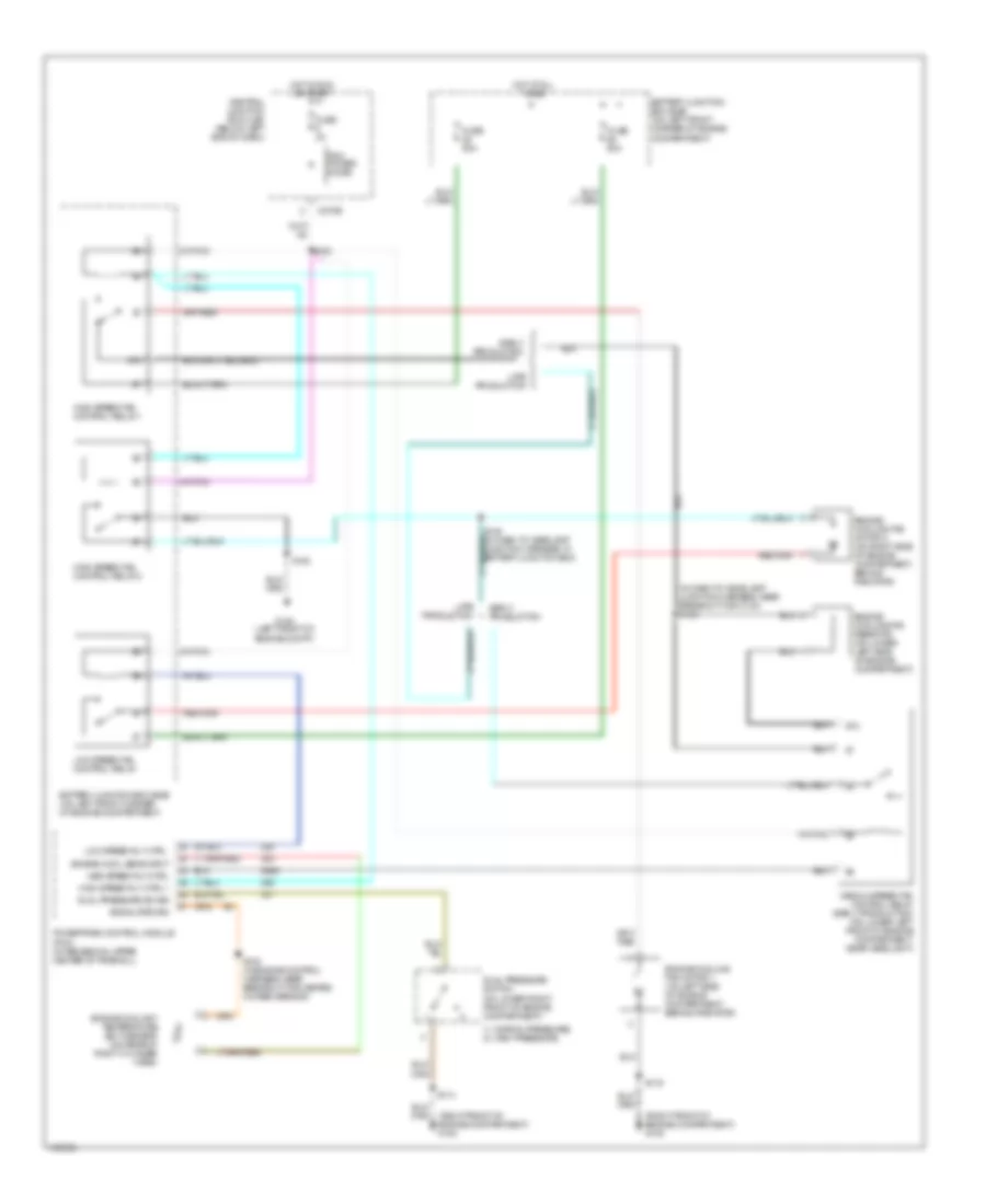
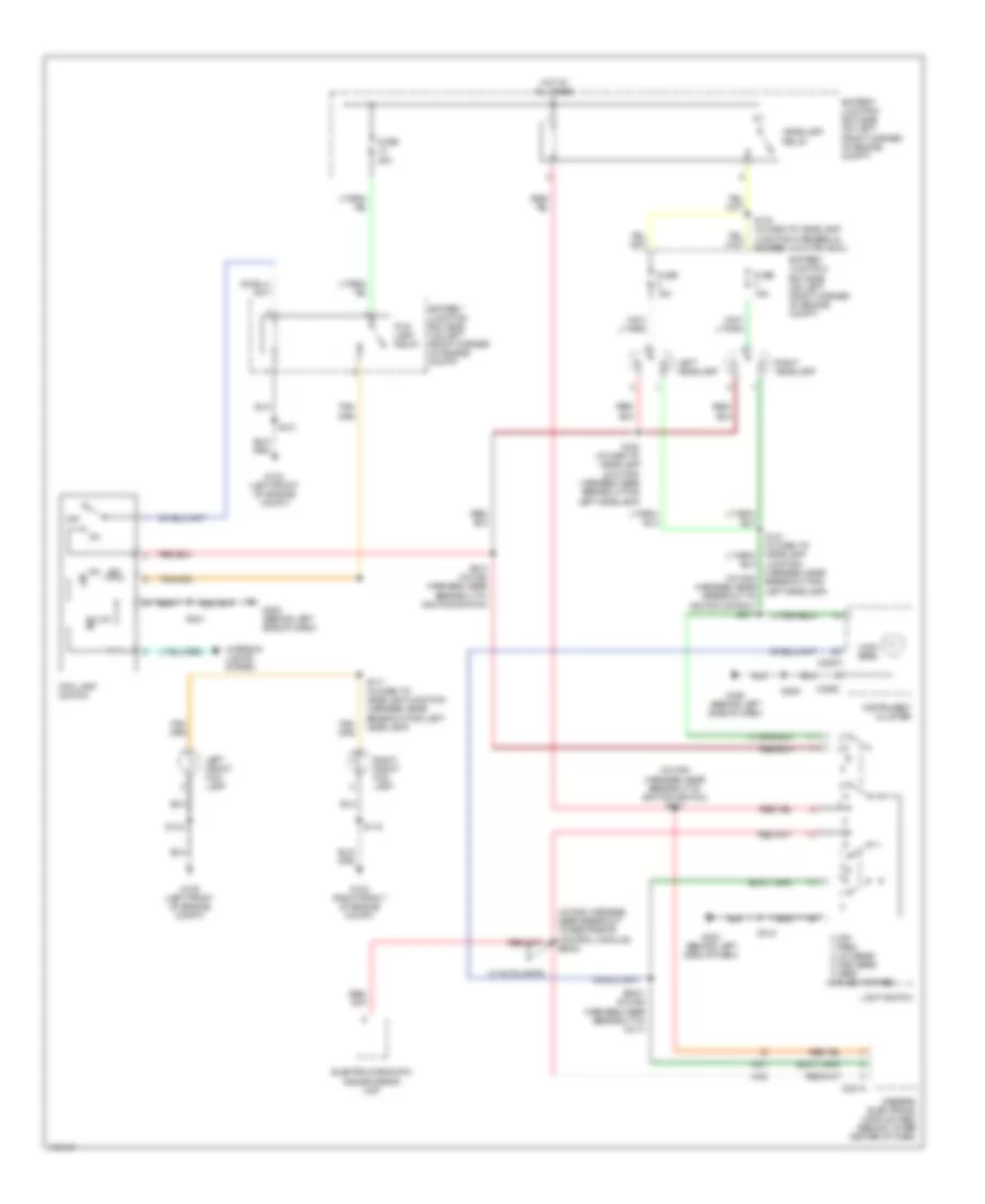
2.0L, Manual A/C Wiring Diagram (2 of 2) for Ford Escape 2003
 https://portal-diagnostov.com/license.html
Automotive Electricians Portal FZCO
Automotive Electricians Portal FZCO
https://portal-diagnostov.com/license.html
https://portal-diagnostov.com/license.html
Automotive Electricians Portal FZCO
Automotive Electricians Portal FZCOList of elements for 2.0L, Manual A/C Wiring Diagram (2 of 2) for Ford Escape 2003:
- (behind center of dash) g200
- (behind center of dash) g201
- (in dash to headlamp junction harness, near breakout for windshield washer pump motor) s114
- (in main harness, near breakout to front cigar lighter) s203
- (in main harness, near breakout to front blower motor) s200
- (on lower right front of engine compartment) dual pressure switch
- (right front of engine compartment) g103
- 1: normal pressure 2: high pressure
- A/c clutch cycling pressure switch (on right side of engine compartment, near strut tower)
- Blower motor switch
- C294a
- C294b
- C294c
- Defrost
- Floor
- Floor/ vent
- Floor/vent
- Front blower motor resistor assembly (behind right side of dash)
- Function selector switch assembly
- High
- Illumination
- Interior lights system
- Low
- Max
- Medium 1
- Medium 2
- Mix
- Mode switch
- Normal
- Off
- Vent
3.0L
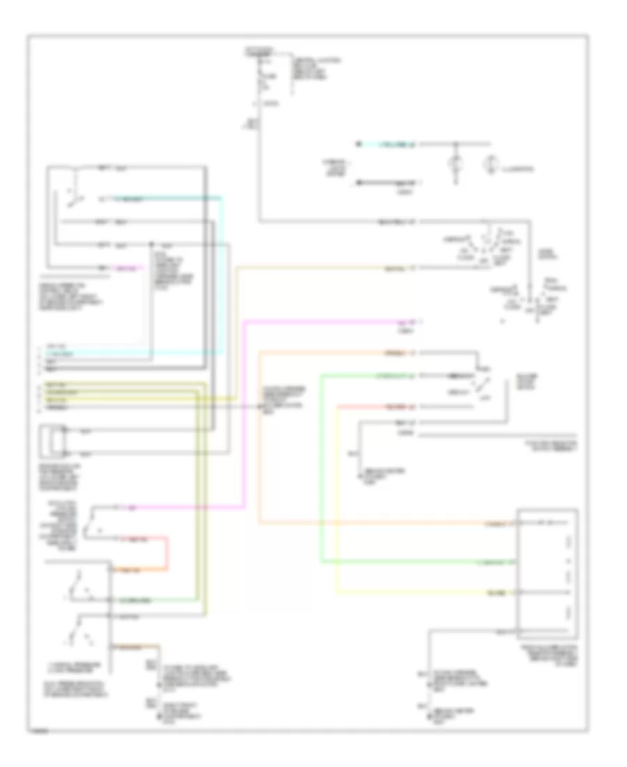
3.0L, Manual A/C Wiring Diagram (1 of 2) for Ford Escape 2003
 https://portal-diagnostov.com/license.html
Automotive Electricians Portal FZCO
Automotive Electricians Portal FZCO
https://portal-diagnostov.com/license.html
https://portal-diagnostov.com/license.html
Automotive Electricians Portal FZCO
Automotive Electricians Portal FZCOList of elements for 3.0L, Manual A/C Wiring Diagram (1 of 2) for Ford Escape 2003:
- (behind left side of dash) g202
- (in dash to headlamp junction harness, in battery junction box)
- (in dash to headlamp junction harness, in battery junction box) s128
- (in dash to headlamp junction harness, in battery junction box) s132
- (in dash to headlamp junction harness, in battery junction box) s145
- (in dash to headlamp junction harness, near breakout for anti-theft hood switch) s115
- (in dash to headlamp junction harness, near breakout for c134) s116
- (in main harness, near breakout to illumination dimmer) s221
- (left front of engine compartment) g104
- (right front of engine compartment) g102
- (right front of engine compartment) g103
- 87a
- A/c clutch relay
- A/c clutch rly ctrl
- A/c clutch solenoid
- A/c compressor clutch diode
- Battery junction box (bjb) (on left front corner of engine compartment)
- Blower motor relay (behind lower left center of dash)
- C270b
- Central junction box (cjb) (below left end of dash)
- Dual pressure sw sig
- Engine coolant sens input
- Engine coolant temperature (ect) sensor (on rear of right cylinder head)
- Engine cooling fan motor 1 (on left side of engine compartment, behind radiator)
- Engine cooling fan motor 2 (on right side of engine compartment, behind radiator)
- Front blower motor (behind right side of dash)
- Fuse 15a
- Fuse 3a
- Fuse 40a
- Fuse 50a
- High speed fan control relay 1
- High speed fan control relay 2
- High speed rly ctrl 1
- Hot at all times
- Hot in run or start
- Low speed fan control relay
- Low speed rly ctrl
- Med speed rly ctrl
- Pcm power diode
- Powertrain control module (pcm) (in recess on upper center of firewall)
- S100 (near breakout for heated oxygen sensor 11)
- S132
- Signal return
3.0L, Manual A/C Wiring Diagram (2 of 2) for Ford Escape 2003
 https://portal-diagnostov.com/license.html
Automotive Electricians Portal FZCO
Automotive Electricians Portal FZCO
https://portal-diagnostov.com/license.html
https://portal-diagnostov.com/license.html
Automotive Electricians Portal FZCO
Automotive Electricians Portal FZCOList of elements for 3.0L, Manual A/C Wiring Diagram (2 of 2) for Ford Escape 2003:
- (behind center of dash) g200
- (behind center of dash) g201
- (in dash to headlamp junction harness, near breakout for windshield washer pump motor) s114
- (in main harness, near breakout to front blower motor) s200
- (in main harness, near breakout to front cigar lighter) s203
- (right front of engine compartment) g103
- 1: normal pressure 2: high pressure
- 87a
- A/c clutch cycling pressure switch (on right side of engine compartment, near strut tower)
- Blower motor switch
- C270c
- C294a
- C294b
- C294c
- Central junction box (cjb) (below left end of dash)
- Defrost
- Dual pressure switch (on lower right front of engine compartment)
- Engine cooling fan resistor (on lower left side of engine compartment)
- Floor
- Floor/ vent
- Front blower motor resistor assembly (behind right side of dash)
- Function selector switch assembly
- Fuse 5a
- High
- Hot in run or start
- Illumination
- Interior lights system
- Low
- Max
- Medium 1
- Medium 2
- Medium speed fan control relay (on lower left front of engine compartment, near headlight)
- Mix
- Mode switch
- Normal
- Off
- S135 (in dash to headlamp junction harness, near breakout for c134)
- Vent
ANTI-LOCK BRAKES
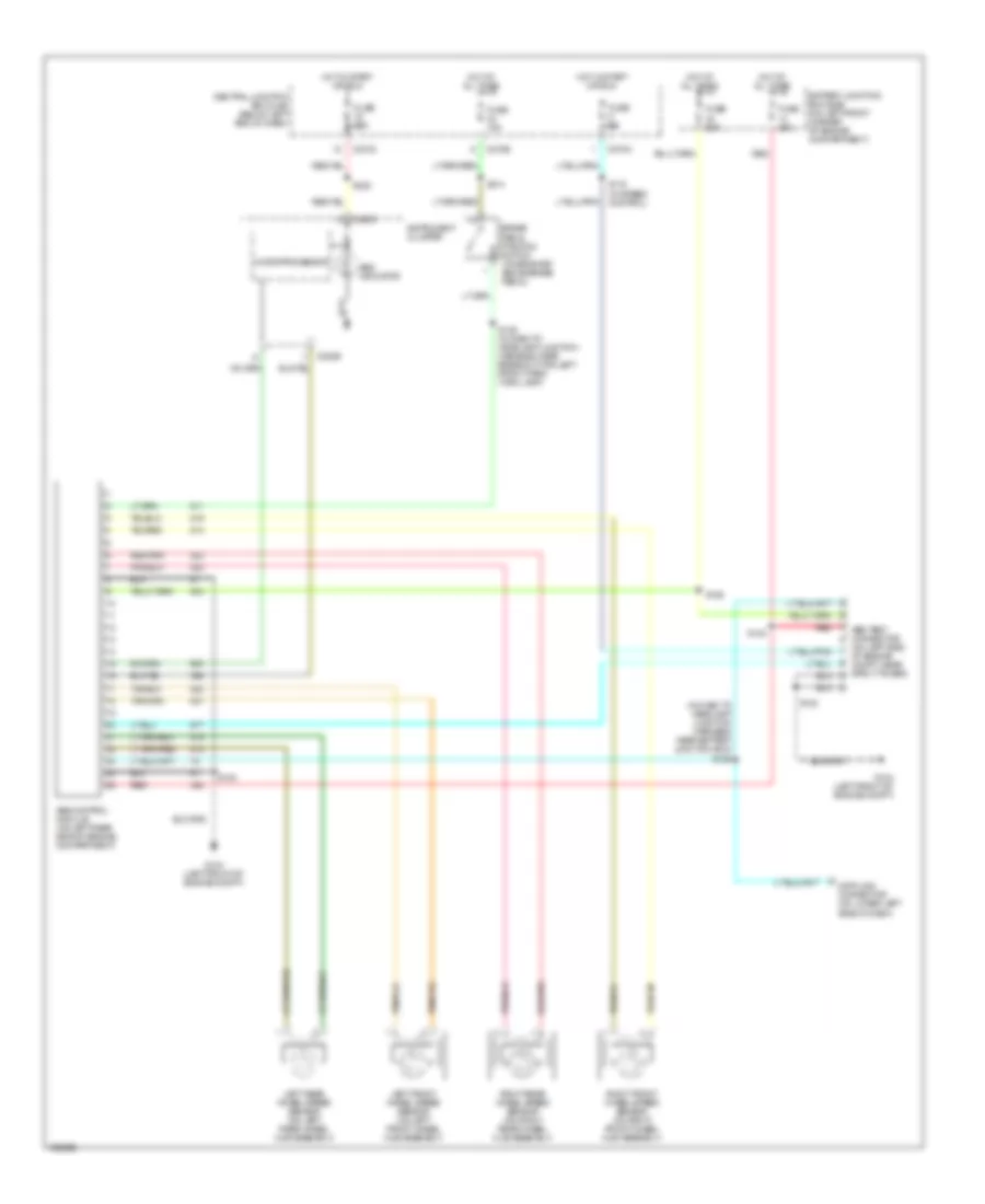
Anti-lock Brakes Wiring Diagram for Ford Escape 2003
 https://portal-diagnostov.com/license.html
Automotive Electricians Portal FZCO
Automotive Electricians Portal FZCO
https://portal-diagnostov.com/license.html
https://portal-diagnostov.com/license.html
Automotive Electricians Portal FZCO
Automotive Electricians Portal FZCOList of elements for Anti-lock Brakes Wiring Diagram for Ford Escape 2003:
- (in dash to headlamp junction harness, near battery junction box) s125
- (on left side of engine compt, near strut tower)
- Abs control module (on left rear side of engine compartment)
- Abs indicator
- Abs test connector
- Battery junction box (bjb) (on left front corner of engine compartment)
- Brake pedal position switch (on bracket, above brake pedal)
- C220b
- C220c
- C270a
- C270c
- C270e
- Central junction box (cjb) (below left end of dash)
- Data link connector (on lower left side of dash)
- Fuse 10a
- Fuse 15a
- Fuse 25a
- Fuse 5a
- Fuse 60a
- G104 (left front of engine compt)
- Hot at all times
- Hot in start or run
- Instrument cluster
- Left front wheel speed sensor (on left front wheel hub assembly)
- Left rear wheel speed sensor (on left rear wheel hub assembly)
- Microprocessor
- Red
- Red/pnk
- Right front wheel speed sensor (on right front wheel hub assembly)
- Right rear wheel speed sensor (on right rear wheel hub assembly)
- S119 (w/ speed control)
- S123
- S124
- S126
- S132
- S139 (in dash to headlamp junction harness, near breakout for left front park/ turn lamp)
- S222
- S314
ANTI-THEFT
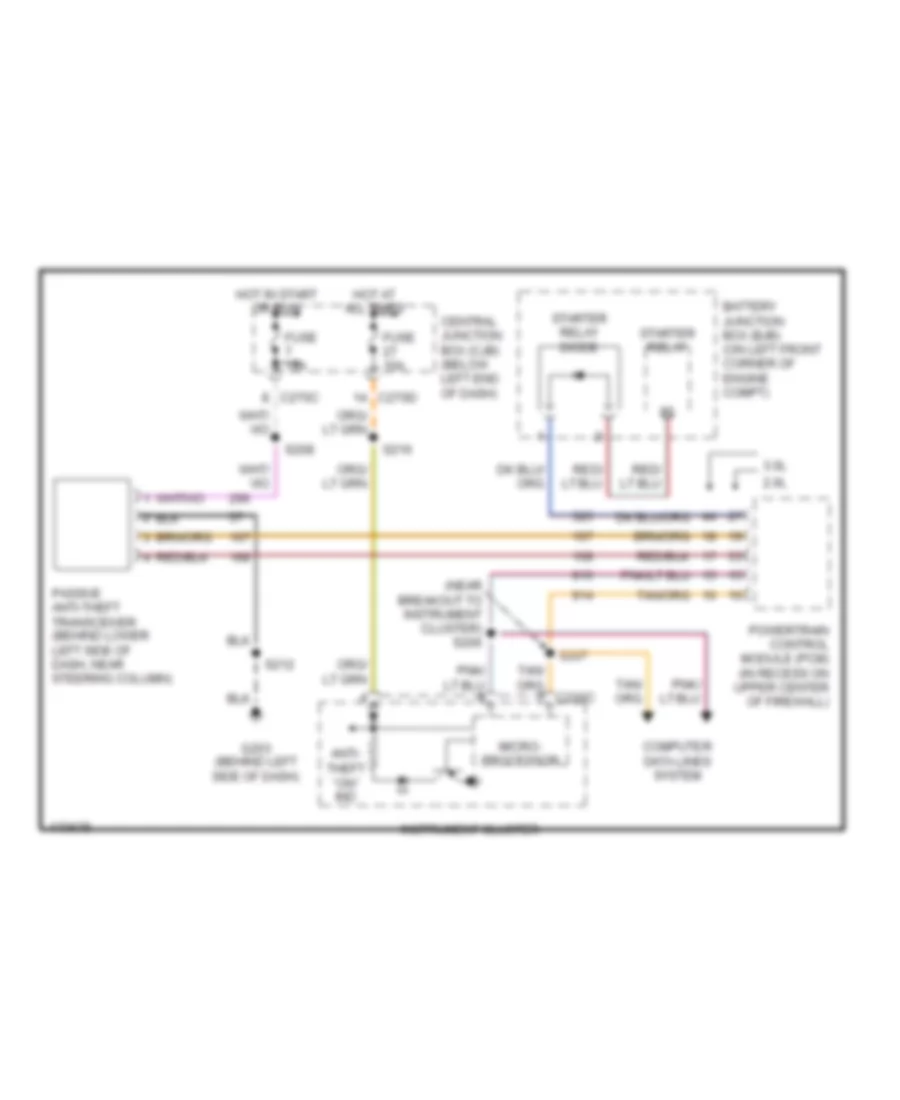
Passive Anti-theft Wiring Diagram for Ford Escape 2003
 https://portal-diagnostov.com/license.html
Automotive Electricians Portal FZCO
Automotive Electricians Portal FZCO
https://portal-diagnostov.com/license.html
https://portal-diagnostov.com/license.html
Automotive Electricians Portal FZCO
Automotive Electricians Portal FZCOList of elements for Passive Anti-theft Wiring Diagram for Ford Escape 2003:
- (near breakout to instrument cluster) s206
- 2.0l
- 3.0l
- Anti- theft "on" ind
- Battery junction box (bjb) (on left front corner of engine compt)
- C270c
- C270d
- Central junction box (cjb) (below left end of dash)
- Computer data lines system
- Fuse 10a
- G203 (behind left side of dash)
- Hot at all times
- Hot in start or run
- Instrument cluster
- Micro- processor
- Passive anti-theft transceiver (behind lower left side of dash, near steering column)
- Powertrain control module (pcm) (in recess on upper center of firewall)
- S207
- S208
- S212
- S216
- Starter relay
- Starter relay diode
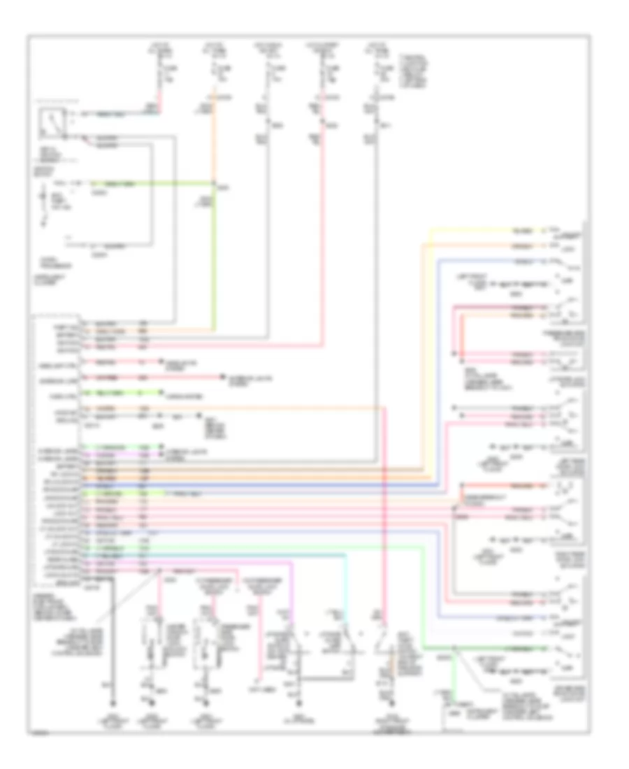
Power Door Locks Wiring Diagram for Ford Escape 2003
 https://portal-diagnostov.com/license.html
Automotive Electricians Portal FZCO
Automotive Electricians Portal FZCO
https://portal-diagnostov.com/license.html
https://portal-diagnostov.com/license.html
Automotive Electricians Portal FZCO
Automotive Electricians Portal FZCOList of elements for Power Door Locks Wiring Diagram for Ford Escape 2003:
- (in taillamps harness, near breakout to evap canister vent control solenoid)
- (left front floor) g300
- (left front floor) g301
- (near breakout to g300)
- (not used)
- Ajar
- Anti- theft "on" ind
- Anti- theft hood switch (on right end of radiator support)
- Battery
- C201a
- C201b
- C220a
- C220c
- C270c
- C270d
- C270e
- Central junction box (cjb) (below left end of dash)
- Driver side front door lock unit
- Exterior lights system
- Exterior lmps
- Fuse 10a
- Fuse 30a
- G103 (right front of engine compartment)
- G201 (behind center of dash)
- G300 (left front floor)
- G301 (left front floor)
- G401 (in liftgate)
- Generic electronic module (gem) (behind lower center of dash)
- Ground
- Headlamp ctrl
- Headlights system
- Hood sw
- Horn ctrl
- Horns system
- Hot at all times
- Hot in run or acc
- Hot in start or run
- Ignition
- Ignition switch
- Instrument cluster
- Interior lamps
- Interior lights system
- Key in ignition switch
- Left rear door lock actuator
- Lf door ajar
- Lf lock in
- Lf unlock in
- Lf unlock out
- Liftgate ajar
- Liftgate ajar switch (on top center of liftgate)
- Liftgate glass ajar switch
- Liftgate lock actuator
- Lock
- Lock out
- Lock/unlk in
- Lr door ajar
- Master window/ door lock/ unlock unlock
- Micro- processor
- Passenger side door lock switch unlock
- Passenger side front door lock unit
- Rear glass
- Rf door ajar
- Rf lock in
- Rf unlock in
- Right rear door lock actuator
- Rr door ajar
- S115
- S2002
- S205
- S216
- S220
- S222
- S302
- S305 (in taillamps harness, near breakout to c421)
- S308
- S309
- S311
- S320
- S401
- S500
- S600
- Switch
- Theft ind
- Unlock
- Unlock out
- Vref
- W/ passenger door lock switch
- W/o passenger door lock switch
BODY CONTROL MODULES
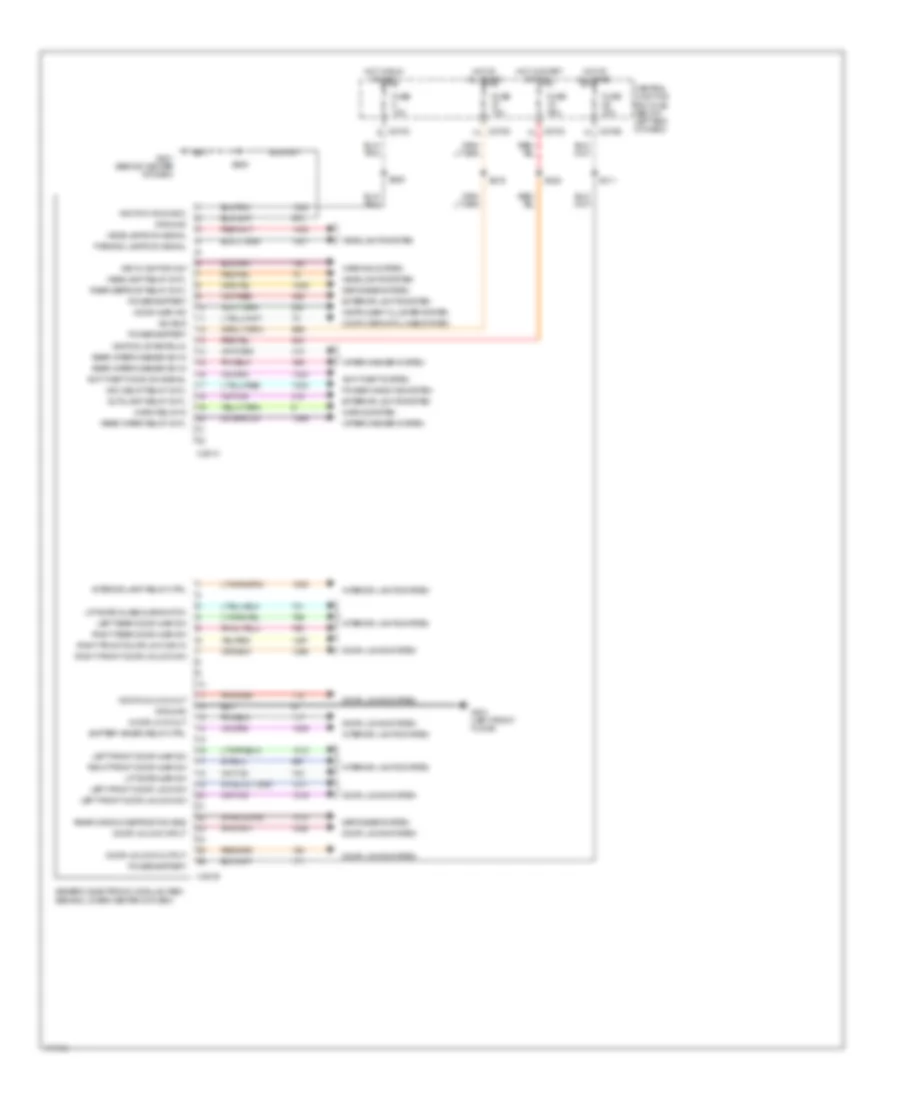
Body Control Modules Wiring Diagram for Ford Escape 2003
 https://portal-diagnostov.com/license.html
Automotive Electricians Portal FZCO
Automotive Electricians Portal FZCO
https://portal-diagnostov.com/license.html
https://portal-diagnostov.com/license.html
Automotive Electricians Portal FZCO
Automotive Electricians Portal FZCOList of elements for Body Control Modules Wiring Diagram for Ford Escape 2003:
- Acc delay relay cntl
- Anti-theft hood sw signal
- Anti-theft system
- Autolamp relay cntl
- Battery saver relay ctrl
- C201a
- C201b
- C270c
- C270d
- C270e
- Central junction box (cjb) (below left end of dash)
- Computer data lines system
- Defogger system
- Door ajar ind
- Door lock out
- Door locks system
- Door unlock input
- Door unlock out
- Door unlock output
- Exterior lights system
- Fuse 10a
- Fuse 30a
- G201 (behind center of dash)
- G301 (left front floor)
- Generic electronic module (gem) (behind lower center of dash)
- Ground
- Headlamp relay cntl
- Headlamps on signal
- Headlights system
- Horn relay in
- Horns system
- Hot at all times
- Hot in run or acc
- Hot in start or run
- Ignition (run/acc)
- Ignition (start/run)
- Instrument cluster system
- Interior lamp relay ctrl
- Interior lights system
- Iso bus
- Key in ignition sw
- Left front door ajar sw
- Left front door lock sw
- Left front door unlock sw
- Left rear door ajar sw
- Liftgate ajar sw
- Liftgate glass ajar switch
- Parking lamps on signal
- Power windows system
- Power-battery
- Rear defrost relay cntl
- Rear window defrost sw sns
- Rear wiper relay cntl
- Rear wiper/washer sw in
- Right front door ajar sw
- Right front door lock sw in
- Right front door unlock sw
- Right rear door ajar sw
- S205
- S216
- S220
- S222
- S311
- Warning system
- Wiper/washer system
COMPUTER DATA LINES
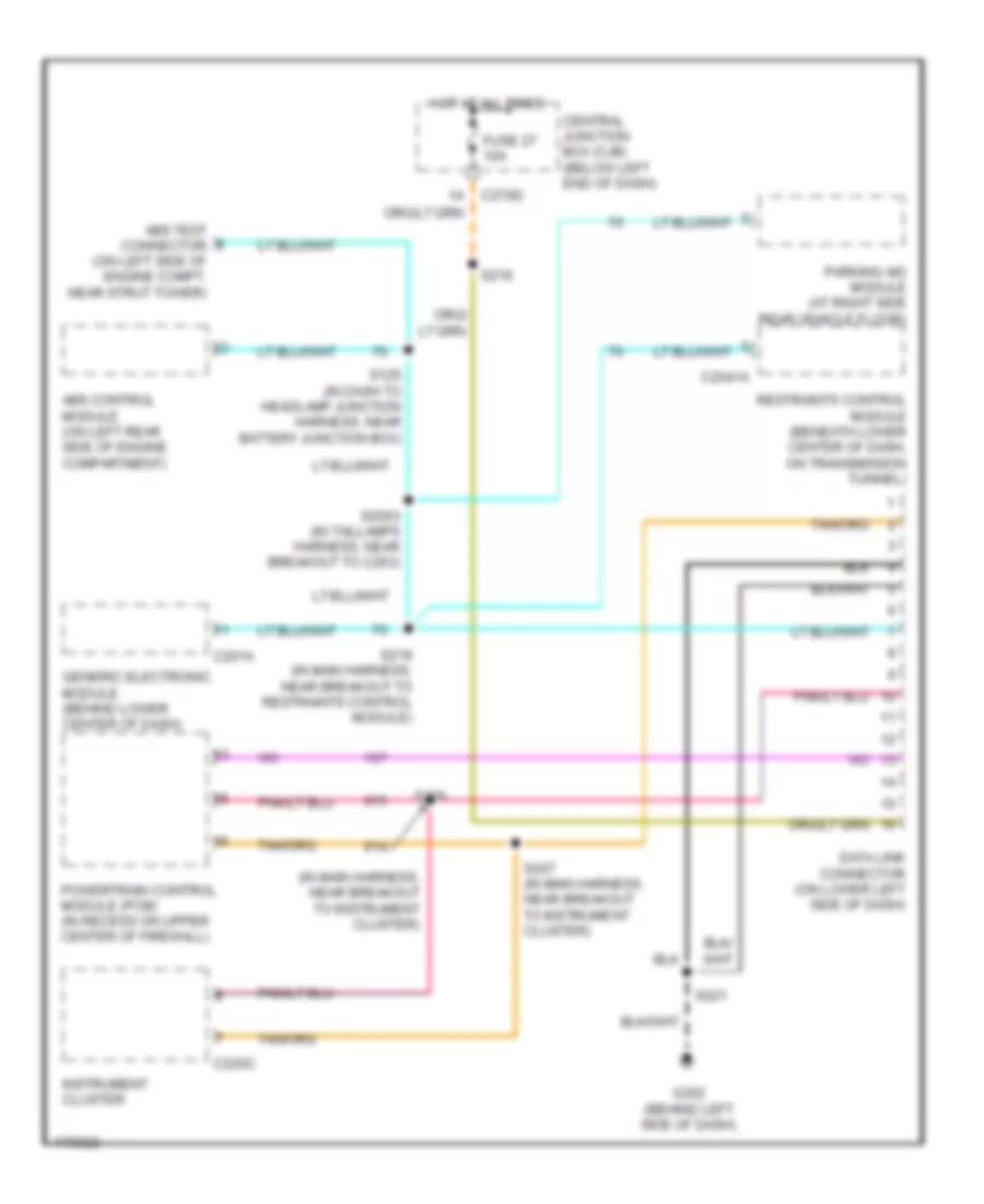
Computer Data Lines Wiring Diagram for Ford Escape 2003
 https://portal-diagnostov.com/license.html
Automotive Electricians Portal FZCO
Automotive Electricians Portal FZCO
https://portal-diagnostov.com/license.html
https://portal-diagnostov.com/license.html
Automotive Electricians Portal FZCO
Automotive Electricians Portal FZCOList of elements for Computer Data Lines Wiring Diagram for Ford Escape 2003:
- (in main harness, near breakout to instrument cluster)
- Abs control module (on left rear side of engine compartment)
- Abs test connector (on left side of engine compt, near strut tower)
- C201a
- C2041a
- C220c
- C270d
- Central junction box (cjb) (below left end of dash)
- Data link connector (on lower left side of dash)
- Fuse 27 10a
- G202 (behind left side of dash)
- Generic electronic module (behind lower center of dash)
- Hot at all times
- Instrument cluster
- Parking aid module (at right side rear vehicle floor)
- Powertrain control module (pcm) (in recess on upper center of firewall)
- Restraints control module (beneath lower center of dash, on transmission tunnel)
- S125 (in dash to headlamp junction harness, near battery junction box)
- S2003 (in taillamps harness, near breakout to c263)
- S206
- S207 (in main harness, near breakout to instrument cluster)
- S216
- S219 (in main harness, near breakout to restraints control module)
- S221
COOLING FAN
2.0L
2.0L, Cooling Fan Wiring Diagram for Ford Escape 2003
 https://portal-diagnostov.com/license.html
Automotive Electricians Portal FZCO
Automotive Electricians Portal FZCO
https://portal-diagnostov.com/license.html
https://portal-diagnostov.com/license.html
Automotive Electricians Portal FZCO
Automotive Electricians Portal FZCOList of elements for 2.0L, Cooling Fan Wiring Diagram for Ford Escape 2003:
- (1: normal pressure) (2: high pressure)
- (in dash to headlamp junction harness, in battery junction box) s127
- (left front of engine compartment) g104
- (right front of engine compartment) g102
- (right front of engine compartment) g103
- Battery junction box (bjb) (on left front corner of engine compartment)
- C270b
- Central junction box (cjb) (below left end of dash)
- Cyl temp sensor input
- Cylinder head temperature sensor (on right front of cylinder head)
- Dual pressure sw sig
- Dual pressure switch (on lower right front of engine compartment)
- Engine cooling fan motor 1 (on left side of engine compartment, behind radiator)
- Engine cooling fan motor 2 (on right side of engine compartment, behind radiator)
- Fuse 3a
- Fuse 40a
- High speed fan control relay 1
- High speed rly ctrl 1
- Hot at all times
- Hot in run or start
- Low speed fan control relay
- Low speed rly ctrl
- Med speed rly ctrl
- Medium speed fan control relay
- Pcm power diode
- Powertrain control module (pcm) (in recess on upper center of firewall)
- S100 (in engine control harness, near breakout for oil pressure switch)
- S114
- S116
- S128
- S132
- S144
- Signal return
3.0L
3.0L, Cooling Fan Wiring Diagram for Ford Escape 2003
 https://portal-diagnostov.com/license.html
Automotive Electricians Portal FZCO
Automotive Electricians Portal FZCO
https://portal-diagnostov.com/license.html
https://portal-diagnostov.com/license.html
Automotive Electricians Portal FZCO
Automotive Electricians Portal FZCOList of elements for 3.0L, Cooling Fan Wiring Diagram for Ford Escape 2003:
- (1: normal pressure) (2: high pressure)
- (in dash to headlamp junction harness, near breakout for c134) s135
- (right front of engine compartment) g102
- (right front of engine compartment) g103
- 87a
- Battery junction box (bjb) (on left front corner of engine compartment)
- C270b
- Central junction box (cjb) (below left end of dash)
- Dual pressure sw sig
- Dual pressure switch (on lower right front of engine compartment)
- Early production
- Engine cool sens input
- Engine coolant temperature (ect) sensor (on rear of right cylinder head)
- Engine cooling fan motor 1 (on left side of engine compartment, behind radiator)
- Engine cooling fan motor 2 (on right side of engine compartment, behind radiator)
- Engine cooling fan resistor (on lower left side of engine compartment)
- Fuse 3a
- Fuse 50a
- G104 (left front of engine compt)
- High speed fan control relay 1
- High speed fan control relay 2
- High speed rly ctrl 1
- Hot at all times
- Hot in run or start
- Late production
- Low speed fan control relay
- Low speed rly ctrl
- Med speed rly ctrl
- Medium speed fan control relay (early production) (on lower left front of engine compartment, near headlight)
- Pcm power diode
- Powertrain control module (pcm) (in recess on upper center of firewall)
- S100 (in engine control harness, near breakout for heated oxygen sensor)
- S114
- S116
- S128
- S132
- S145 (in dash to headlamp junction harness, in battery junction box)
- Signal return
CRUISE CONTROL
Cruise Control Wiring Diagram for Ford Escape 2003
 https://portal-diagnostov.com/license.html
Automotive Electricians Portal FZCO
Automotive Electricians Portal FZCO
https://portal-diagnostov.com/license.html
https://portal-diagnostov.com/license.html
Automotive Electricians Portal FZCO
Automotive Electricians Portal FZCOList of elements for Cruise Control Wiring Diagram for Ford Escape 2003:
- (near breakout to left side turn signal lamp)
- (on right rear of transmission, near left axle flange) output shaft speed sensor
- (on right side of transmission) vehicle speed sensor
- 2.0l
- 3.0l
- A/t
- Abs test connector (on left side of engine compartment, near strut tower)
- Acc
- Air bag sliding contact
- Brake pedal position switch (on bracket, above brake pedal)
- C218a
- C220b
- C220c
- C270a
- C270c
- C270d
- C270e
- Central junction box (cjb) (below left end of dash)
- Clutch switch (on bracket, above clutch pedal)
- Coast
- Deact- ivator switch (on bracket, above brake pedal)
- Fuse 10a
- Fuse 15a
- Fuse 5a
- G101 (top center of transmission)
- G103 (right front of engine compartment)
- Horn
- Horns system
- Hot at all times
- Hot in start or run
- Ignition switch
- Instrument cluster
- Limited
- M/t
- Nca
- Near breakout to c263)
- Off
- Powertrain control module (pcm) (in recess on upper center of firewall)
- Rest
- Resume
- Run
- S1002
- S107
- S114
- S119 (near breakout for left headlamp)
- S137 (2.0l)
- S139 (near breakout for left front park/turn lamp)
- S222
- S314
- Set/accelerate
- Sound systems
- Speed control servo (on right side of engine compartment)
- Speed control indicator
- Speed control off
- Speed control on
- Start
- Steering wheel/speed control switch
- Turbine shaft speed sensor (on right rear of transmission)
- W/ abs
DEFOGGERS
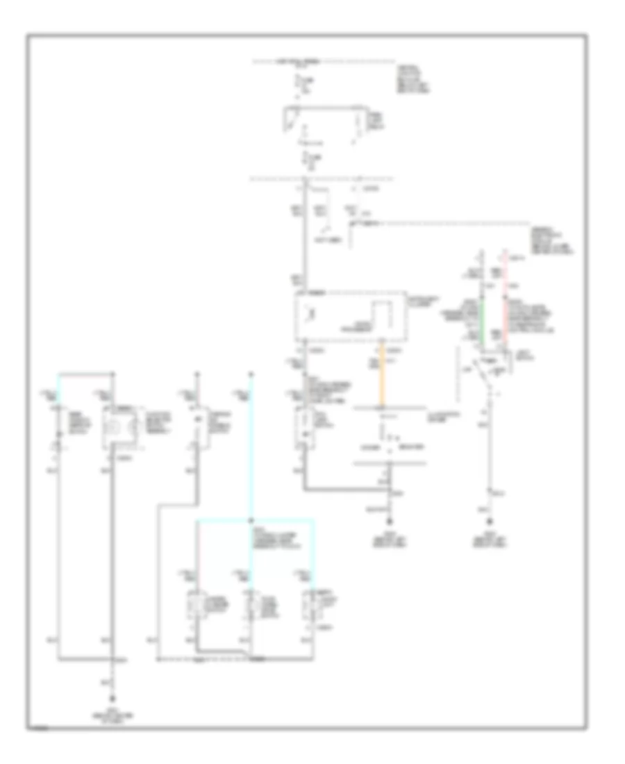
Defoggers Wiring Diagram for Ford Escape 2003
 https://portal-diagnostov.com/license.html
Automotive Electricians Portal FZCO
Automotive Electricians Portal FZCO
https://portal-diagnostov.com/license.html
https://portal-diagnostov.com/license.html
Automotive Electricians Portal FZCO
Automotive Electricians Portal FZCOList of elements for Defoggers Wiring Diagram for Ford Escape 2003:
- Battery junction box (bjb) (on left front corner of engine compt)
- C201a
- C201b
- C270a
- C402a
- C402b
- Central junction box (cjb) (below left end of dash)
- Defroster on indicator
- Driver side exterior rear view mirror
- Fuse 16 10a
- Fuse 30a
- G201 (behind center of dash)
- G300 (left front floor)
- G301 (left front floor)
- G400 (in liftgate)
- Generic electronic module (behind lower center of dash)
- Hot at all times
- Hot in start or run
- Illum
- Interior lights system
- Nca
- Off
- Passenger side exterior rear view mirror
- Rear window defrost grid
- Rear window defrost relay
- Rear window defrost switch
- S1000
- S203
- S330 (in taillamps harness, near breakout to c263)
- S500
- S600
ENGINE PERFORMANCE
2.0L
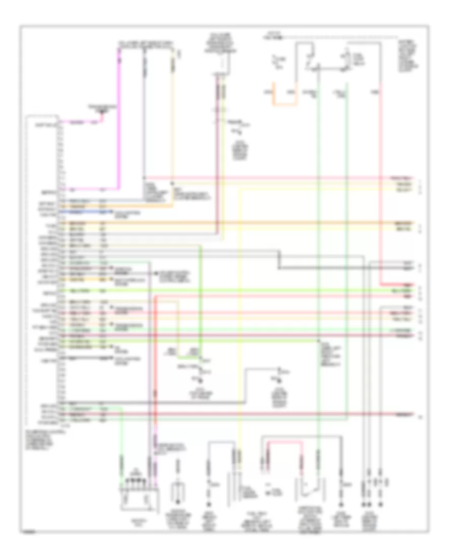
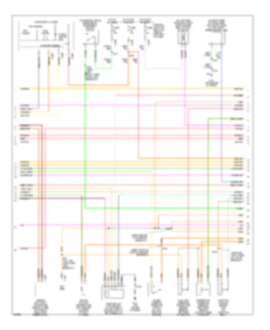
2.0L, Engine Performance Wiring Diagram (1 of 3) for Ford Escape 2003
 https://portal-diagnostov.com/license.html
Automotive Electricians Portal FZCO
Automotive Electricians Portal FZCO
https://portal-diagnostov.com/license.html
https://portal-diagnostov.com/license.html
Automotive Electricians Portal FZCO
Automotive Electricians Portal FZCOList of elements for 2.0L, Engine Performance Wiring Diagram (1 of 3) for Ford Escape 2003:
- (on lower left side of dash) data link connector (dlc)
- (on lower left side of engine block) crankshaft position sensor
- A/c system
- Battery junction box (bjb) (on left front corner of engine compt)
- C175
- C251
- Cht
- Ckp sens
- Cooling fans system
- Cruise control system (speed control servo)
- Dual press
- Eeprom
- Fp driver
- Fuel gauge sensor
- Fuel pump
- Fuel pump relay
- Fuel tank unit (beneath left rear of vehicle, in fuel tank)
- Fuse 20a
- G100 (center rear of engine compt)
- G101 (top center of trans)
- G203 (behind left side of dash)
- G402 (left rear end of vehicle)
- Ground
- High fan
- Ho2s 12
- Hot at all times
- Ign coil
- Ignition coil
- Ignition transformer capacitor 1 (on rear of cyl head)
- Inertia fuel shutoff (ifs) switch (at base of right door pillar, near kick panel)
- Inj 3
- Maf
- Med fan
- Nca
- O/d sw sig
- Plugs
- Powertrain control module (pcm) (in recess on upper center of firewall)
- Psp sw
- Red
- Rx cntl
- S101
- S102
- S104
- S106
- S107
- S112
- S113
- S138 (near left front park/turn lamp breakout)
- S205
- S206 (near instrument cluster breakout)
- S207 (near instrument cluster breakout)
- S309
- Scp bus +
- Scp bus -
- Sens ret
- Shift interlock system
- Shift sol b
- Start rly
- Starting system
- Tft sen v ref
- To spark
- Transmissions system
- Tur shaft ss
- Tx sig
- Vss out
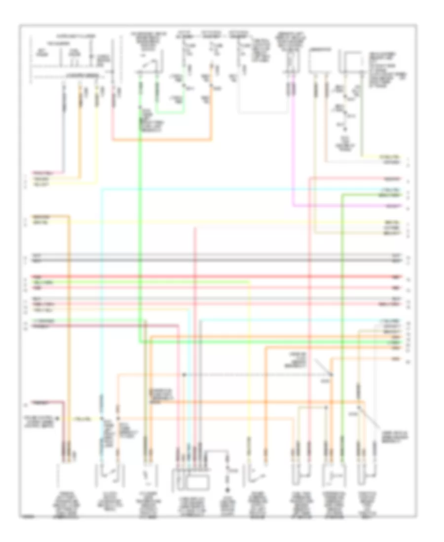
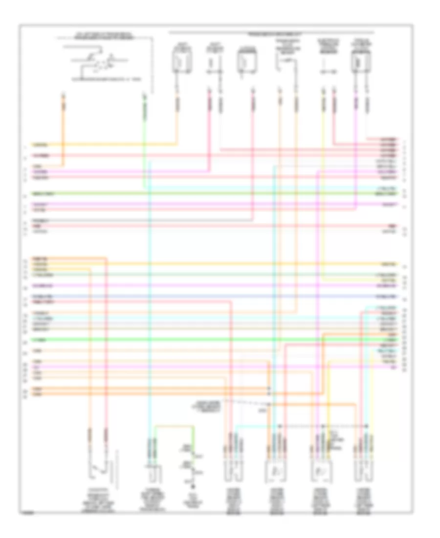
2.0L, Engine Performance Wiring Diagram (2 of 3) for Ford Escape 2003
 https://portal-diagnostov.com/license.html
Automotive Electricians Portal FZCO
Automotive Electricians Portal FZCO
https://portal-diagnostov.com/license.html
https://portal-diagnostov.com/license.html
Automotive Electricians Portal FZCO
Automotive Electricians Portal FZCOList of elements for 2.0L, Engine Performance Wiring Diagram (2 of 3) for Ford Escape 2003:
- (a/t)
- (beneath left rear of vehicle) evap canister vent control solenoid
- (near air flow sensor breakeout)
- (near fuel injector 4 breakeout) s154
- (near vehicle speed sensor breakout)
- (on bracket, above brake pedal) brake pedal position switch
- C2007
- C220a
- C220c
- C270c
- C270e
- C270f
- Central junction box (cjb) (below left end of dash)
- Check engine ind
- Clutch switch (on bracket, above clutch pedal)
- Cruise control system (speed control servo)
- Cylinder head temperature sensor (on right front of cyl head)
- Differential pressure feedback egr (dpfe) sensor (on rear of engine)
- Ect gauge
- Fuel gauge
- Fuel tank pressure transducer sensor (beneath left rear of vehicle)
- Fuse 10a
- Fuse 15a
- Fuse 5a
- G100 (center rear of engine compt)
- G101 (top center of trans)
- Generator
- Hot at all times
- Hot in run or start
- Instrument cluster
- Mass airflow (maf) sensor (near rear of cyl head, in air intake duct)
- Microprocessor
- Passive anti-theft transceiver (behind lower left side of dash, near steering col)
- Power steering pressure switch (on left front of engine)
- Red
- Red/pnk
- S105
- S106
- S107
- S109
- S112
- S137 (near left front park/ trun lamp)
- S222
- S313 (near breakout to c263)
- S314
- Tachometer
- Throttle position sensor (tps) (on throttle body)
- Vehicle speed sensor (vss) (m/t) (on right side of trans) output shaft speed (oss) sensor (right rear of trans)
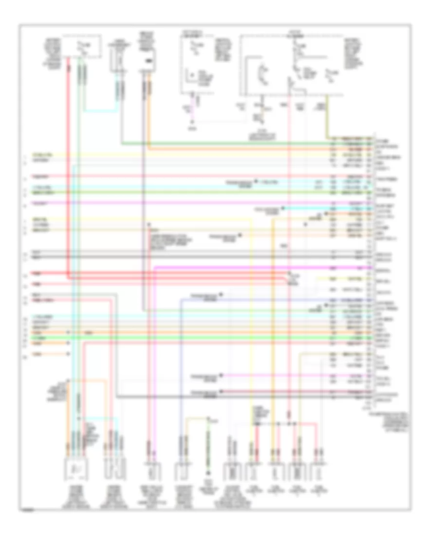
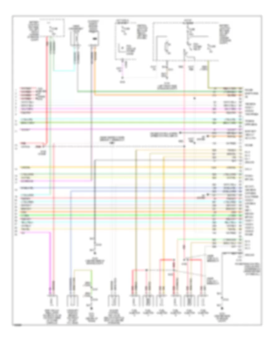
2.0L, Engine Performance Wiring Diagram (3 of 3) for Ford Escape 2003
 https://portal-diagnostov.com/license.html
Automotive Electricians Portal FZCO
Automotive Electricians Portal FZCO
https://portal-diagnostov.com/license.html
https://portal-diagnostov.com/license.html
Automotive Electricians Portal FZCO
Automotive Electricians Portal FZCOList of elements for 2.0L, Engine Performance Wiring Diagram (3 of 3) for Ford Escape 2003:
- (a/t)
- (behind intake manifold) knock sensor
- (m/t)
- (near breakout for vehicle speed sensor/ output shaft speed sensor)
- (near injector 4 break- out) s152
- 3-2t/ccs sig
- A/c cltch
- A/c system
- Battery junction box (bjb) (on left front corner of engine compt)
- Bpp sw
- C175
- C270b
- Camshaft position sensor (on right rear of cyl head)
- Central junction box (cjb) (below left end of dash)
- Cmp sens
- Cooling fans system
- Dpfe sens
- Dual press
- Egr sol
- Egr vacuum regulator solenoid valve (near throttle body)
- Epc sol
- Evap purge
- Evap vent
- Fuel injector
- Fuse 15a
- Fuse 30a
- Fuse 3a
- Fuse 5a
- G101 (top center of trans)
- G104 (left front of engine compt)
- Gen
- Ground
- Heated oxygen sensor (ho2s) 11 (left front side of engine)
- Heated oxygen sensor (ho2s) 12 (left front side of engine)
- Ho2s 11
- Ho2s 12
- Hot at all times
- Hot in run or start
- Iac cntl
- Idle air control (iac) valve (on right side of engine, attached to intake manifold)
- Inj 1
- Inj 2
- Inj 4
- Low fan
- Maf sens
- Pcm module power diode
- Pcm power relay
- Power
- Powertrain control module (pcm) (in recess on upper center of firewall)
- Red
- Red/pnk
- Ref v
- Return
- S100 (near oil pressure switch breakout)
- S103
- S107
- S111 (near gen- erator break- out)
- S128
- S129 (in bjb)
- S131
- Shift sol a
- Tan
- Tank press
- Tcc sol
- Tps
- Tr sens
- Transmissions system
- Vapor management valve
- Vss/oss sens
3.0L
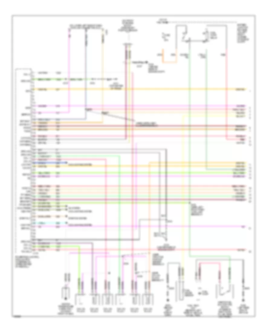
3.0L, Engine Performance Wiring Diagram (1 of 4) for Ford Escape 2003
 https://portal-diagnostov.com/license.html
Automotive Electricians Portal FZCO
Automotive Electricians Portal FZCO
https://portal-diagnostov.com/license.html
https://portal-diagnostov.com/license.html
Automotive Electricians Portal FZCO
Automotive Electricians Portal FZCOList of elements for 3.0L, Engine Performance Wiring Diagram (1 of 4) for Ford Escape 2003:
- (near coil on plug 6 breakout)
- (near instrument cluster breakout)
- (near throttle position sensor breakout)
- (on front of engine block) crankshaft position sensor
- (on lower left side of dash) data link connector (dlc)
- 3-2t/ccs
- A/c system
- Battery junction box (bjb) (on left front corner of engine compt)
- C175
- C251
- Ckp sens
- Coil 1
- Coil 2
- Coil 4
- Coil 5
- Coil 6
- Coil on plug 1
- Coil on plug 2
- Coil on plug 3
- Coil on plug 4
- Coil on plug 5
- Coil on plug 6
- Cooling fans system
- Dual press
- Ect sens
- Eeprom
- Egr sol
- Fp driver
- Fuel gauge sensor
- Fuel pump
- Fuel pump relay
- Fuel tank unit (beneath left rear of vehicle, in fuel tank)
- Fuse 20a
- G100 (center rear of engine compt)
- G101 (top center of trans)
- G203 (behind left side of dash)
- G402 (left rear end of vehicle)
- Ground
- High fan
- Ho2s 12
- Hot at all times
- Ignition transformer capacitor 1 (on right front of eng)
- Inertia fuel shutoff (ifs) switch (at base of right door pillar, near kick panel)
- Low fan
- Maf
- Med fan
- Nca
- O/d sw
- Powertrain control module (pcm) (in recess on upper center of firewall)
- Psp sw
- Red
- Rx sig
- S104
- S107
- S138 (near left front park/ turn lamp breakout)
- S155
- S156
- S157
- S205
- S206
- S207
- S309
- Scp bus +
- Scp bus -
- Sens ret
- Ss a
- Ss b
- Start rly
- Starting system
- Tcc sol
- Tft sens
- Tx sig
3.0L, Engine Performance Wiring Diagram (2 of 4) for Ford Escape 2003
 https://portal-diagnostov.com/license.html
Automotive Electricians Portal FZCO
Automotive Electricians Portal FZCO
https://portal-diagnostov.com/license.html
https://portal-diagnostov.com/license.html
Automotive Electricians Portal FZCO
Automotive Electricians Portal FZCOList of elements for 3.0L, Engine Performance Wiring Diagram (2 of 4) for Ford Escape 2003:
- (near egr vacuum reg sol valve breakout)
- (near mass air flow sensor breakout)
- (near throttle position sensor breakout)
- (on bracket, above brake pedal) brake pedal position switch
- (on left side of engine compt) evap canister vent control solenoid
- (on right rear of trans, near left axle flange) output shaft speed sensor (oss)
- C2007
- C220a
- C220c
- C248
- C270c
- C270e
- C270f
- Central junction box (cjb) (below left end of dash)
- Check engine ind
- Differential pressure feedback egr (dpfe) sensor (on right rear of engine)
- Ect gauge
- Engine coolant temperature (ect) sensor (on rear of right cyl head)
- Fuel gauge
- Fuel tank pressure transducer sensor (beneath left rear of vehicle)
- Fuse 10a
- Fuse 15a
- Fuse 5a
- G101 (top center of trans)
- Hot at all times
- Hot in run or start
- Instrument cluster
- Mass airflow (maf) sensor (on left side of engine compt, in air intake duct)
- Microprocessor
- Not used
- Passive anti-theft transceiver (behind lower left side of dash, near steering col)
- Power steering pressure switch (on left front of engine)
- Red
- Red/pnk
- S104
- S105
- S106
- S107
- S109
- S154
- S222
- S313 (tail lamp harn, near c263 breakout)
- S314
- Tachometer
- Throttle position sensor (tps) (on throttle body)
3.0L, Engine Performance Wiring Diagram (3 of 4) for Ford Escape 2003
 https://portal-diagnostov.com/license.html
Automotive Electricians Portal FZCO
Automotive Electricians Portal FZCO
https://portal-diagnostov.com/license.html
https://portal-diagnostov.com/license.html
Automotive Electricians Portal FZCO
Automotive Electricians Portal FZCOList of elements for 3.0L, Engine Performance Wiring Diagram (3 of 4) for Ford Escape 2003:
- (near heated oxygen sensor 11 breakout)
- (on left side of transmission) transmission range (tr) sensor
- 3-2t/ccs solenoid
- Brake shift interlock (behind left side of dash, near steering column)
- Electronic pressure control solenoid
- G101 (top center of trans)
- Heated oxygen sensor (ho2s) 11 (right side of engine)
- Heated oxygen sensor (ho2s) 12 (right side of engine)
- Heated oxygen sensor (ho2s) 21 (left rear side of engine)
- Heated oxygen sensor (ho2s) 22 (left rear side of engine)
- O/d switch
- Red
- Red/pnk
- S100
- S104
- S107
- S111 (top center of trans)
- Shift solenoid a
- Shift solenoid b
- Torque converter clutch solenoid
- Transmission fluid temperature sensor
- Transmission hardware unit
- Turbine shaft speed (tss) sensor (on right rear of transmission)
3.0L, Engine Performance Wiring Diagram (4 of 4) for Ford Escape 2003
 https://portal-diagnostov.com/license.html
Automotive Electricians Portal FZCO
Automotive Electricians Portal FZCO
https://portal-diagnostov.com/license.html
https://portal-diagnostov.com/license.html
Automotive Electricians Portal FZCO
Automotive Electricians Portal FZCOList of elements for 3.0L, Engine Performance Wiring Diagram (4 of 4) for Ford Escape 2003:
- (near fuel inj 1 breakout)
- (near fuel inj 2 breakout)
- (near heated oxygen sensor 11 breakout) s103
- (on right side of engine) knock sensor
- (top center of trans) s108
- A/c cltch
- A/c system
- Battery junction box (bjb) (on left front corner of engine compt)
- Bpp sw
- C175
- C270b
- Camshaft position sensor (on front of left cyl head)
- Central junction box (cjb) (below left end of dash)
- Cmp sens
- Coil 3
- Cruise control system (speed control servo)
- Dpfe sens
- Dual press
- Egr vacuum regulator solenoid valve (on right rear of intake manifold)
- Epc sol
- Evap purge
- Evap vent
- Fp driv
- Fuel injector
- Fuse 15a
- Fuse 30a
- Fuse 3a
- Fuse 5a
- G100 (center rear of engine compt)
- G101 (top center of trans)
- G104 (left front side of engine compt)
- Ground
- Ho2s 11
- Ho2s 12
- Ho2s 21
- Ho2s 22
- Hot at all times
- Hot in run or start
- Iac cntl
- Idle air control (iac) valve (below throttle body, on center of engine)
- Inj 1
- Inj 2
- Inj 3
- Inj 4
- Inj 5
- Inj 6
- Maf sens
- Oss sens
- Pcm module power diode
- Pcm power relay
- Power
- Powertrain control module (pcm) (in recess on upper center of firewall)
- Red
- Red/pnk
- Ref v
- Return
- S102
- S104
- S106
- S107
- S128
- S129 (in bjb)
- S131
- S152
- S153
- Tan
- Tank press
- Tps
- Tr sens
- Tss sens
- Vapor management valve
- Vss out
EXTERIOR LIGHTS
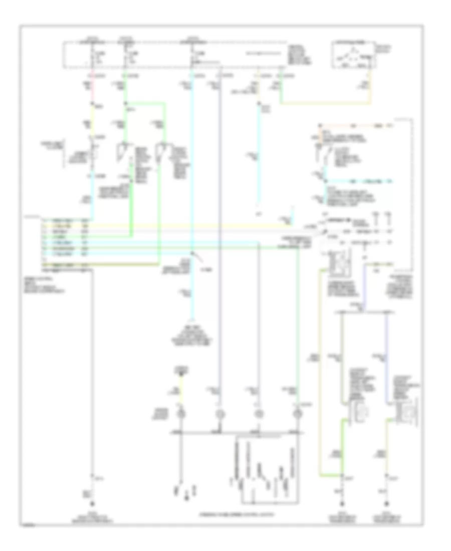
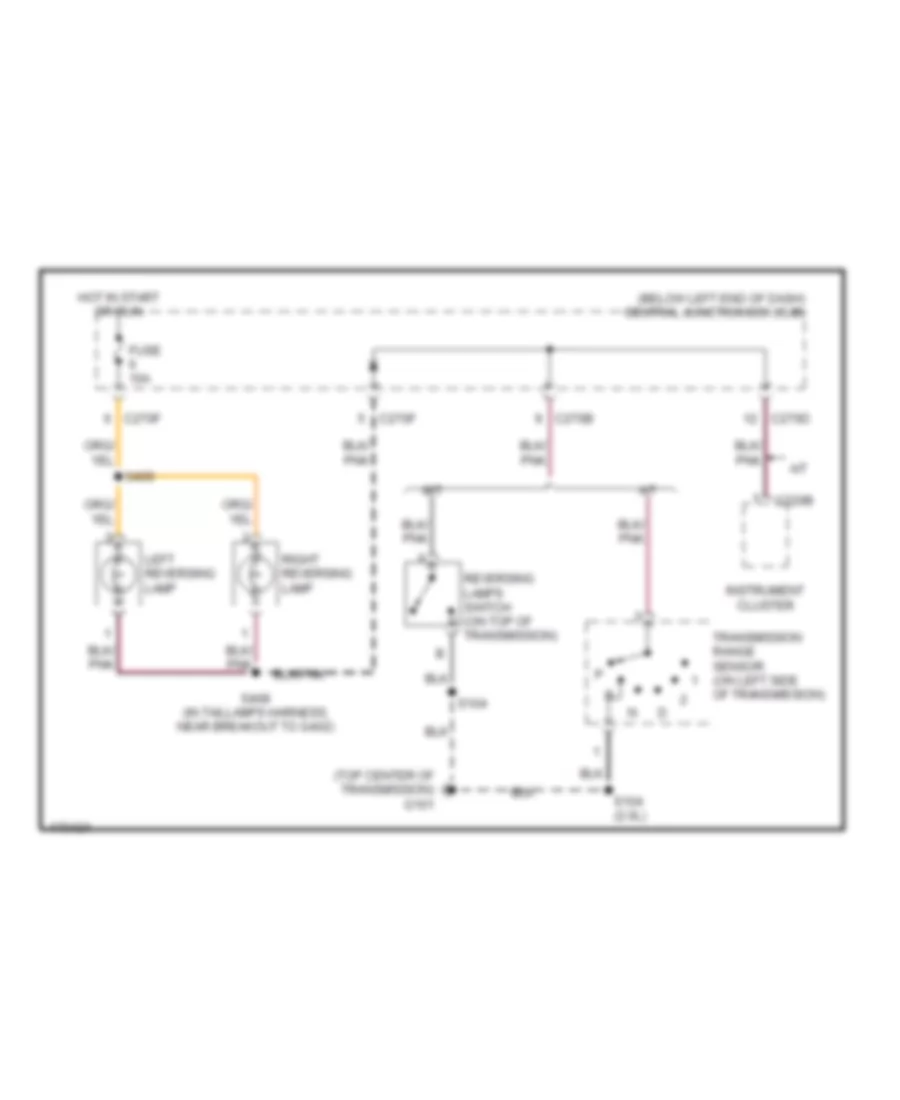
Back-up Lamps Wiring Diagram for Ford Escape 2003
 https://portal-diagnostov.com/license.html
Automotive Electricians Portal FZCO
Automotive Electricians Portal FZCO
https://portal-diagnostov.com/license.html
https://portal-diagnostov.com/license.html
Automotive Electricians Portal FZCO
Automotive Electricians Portal FZCOList of elements for Back-up Lamps Wiring Diagram for Ford Escape 2003:
- (below left end of dash) central junction box (cjb)
- (top center of transmission) g101
- A/t
- C220b
- C270b
- C270d
- C270f
- Fuse 10a
- Hot in start or run
- Instrument cluster
- Left reversing lamp
- M/t
- Reversing lamps switch (on top of transmission)
- Right reversing lamp
- S104
- S104 (2.0l)
- S408 (in taillamps harness, near breakout to g402)
- S409
- Transmission range sensor (on left side of transmission)
Exterior Lamps Wiring Diagram for Ford Escape 2003
 https://portal-diagnostov.com/license.html
Automotive Electricians Portal FZCO
Automotive Electricians Portal FZCO
https://portal-diagnostov.com/license.html
https://portal-diagnostov.com/license.html
Automotive Electricians Portal FZCO
Automotive Electricians Portal FZCOList of elements for Exterior Lamps Wiring Diagram for Ford Escape 2003:
- (behind center of dash) g201
- (behind left side of dash)
- (behind lower center
- (in dash to headlamp junction harness, near breakout for left headlamp) s118
- (in taillamps harness, near breakout to g402)
- (in taillamps harnessn near breakout to g402)
- (near breakout to c211)
- (near breakout to g202)
- (near breakout to left license plate lamp)
- (near breakout to restraints control module)
- (w/ auto lamps) s2000
- Brake pedal position switch (on bracket, above brake pedal)
- Brake switch
- C201a
- C2027a
- C2027b
- C220a
- C220b
- C220c
- C270a
- C270b
- C270c
- C270d
- C270e
- C270f
- Central junction box (cjb) (below left end of dash)
- Electronic flasher module (behind lower left end of dash)
- Flasher feed
- Fuse 10a
- Fuse 15a
- G103 (right front of engine compt)
- G105 (left front of engine compt)
- G202 (behind left side of dash)
- G203
- G203 (behind left side of dash)
- G401 (in liftgate)
- G403 (left rear end of vehicle)
- Generic electronic module
- Grd
- Hazard flasher switch
- High (5) mounted stoplamp
- Hot at all times
- Hot in start or run
- Illumination
- Instrument cluster
- Interior lights system
- Left front park/turn lamp
- Left license plate lamp
- Left rear park/stop lamp
- Left rear turn lamp
- Left side turn signal lamp
- Left sig out
- Left turn
- Left turn signal indicator
- Lft frt turn
- Lft rear turn
- Light switch 0)off 1)park 2)head
- Neutral
- Of dash)
- Park lamp relay
- Right front park/turn lamp
- Right license plate lamp
- Right rear park/stop lamp
- Right rear turn lamp
- Right side turn signal lamp
- Right sig out
- Right turn
- Right turn signal indicator
- Rt frt turn
- Rt rear turn
- S115
- S134
- S136 (in dash to headlamp junction harness, near breakout for left side turn signal lamp)
- S143 (in dash to headlamp junction harness, near breakout for antitheft hood switch)
- S2001
- S205
- S212
- S221
- S223
- S233
- S314
- S400
- S401
- S402
- S403
- S406
- S407
- S414
- Shift interlock system
- Trailer tow connector
- With side turn lamps
GROUND DISTRIBUTION
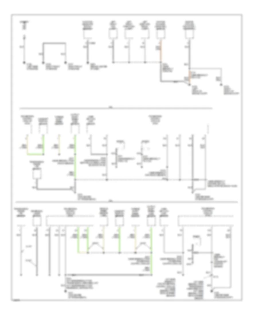
Ground Distribution Wiring Diagram (1 of 3) for Ford Escape 2003
 https://portal-diagnostov.com/license.html
Automotive Electricians Portal FZCO
Automotive Electricians Portal FZCO
https://portal-diagnostov.com/license.html
https://portal-diagnostov.com/license.html
Automotive Electricians Portal FZCO
Automotive Electricians Portal FZCOList of elements for Ground Distribution Wiring Diagram (1 of 3) for Ford Escape 2003:
- (a/t: near breakout for powertrain control module) (m/t: near breakout for vehicle speed
- (a/t: near breakout for transmission hardware unit) (m/t: near breakout for vehicle speed sensor)
- (near breakout for c110)
- (near breakout for crankshaft position sensor)
- (near breakout for egr vacuum regulator solenoid valve)
- (near breakout for knock sensor)
- 2.0l
- 3.0l
- Battery
- C294b
- Camshaft position sensor
- Daytime running lamps (drl) module
- Engine cooling fan motor 1 or motor 2
- Function selector switch assembly
- G100 (center rear of engine compt)
- G101 (top center of transmission)
- G102 (right front of engine compt)
- G105 (left front of engine compt)
- G106 (right front of engine)
- G107 (right front of engine)
- G108 (left rear of engine)
- G200 (behind center of dash)
- Left front fog lamp
- Left front park/turn lamp
- Left side turn signal lamp
- Mass air flow (maf) sensor
- Nca
- Output shaft speed (oss) sensor
- Powertrain control module (pcm)
- Reversing lamps switch
- S101
- S102
- S104
- S104 (a/t: near breakout for transmission hardware unit) (m/t: near breakout for reversing lamps switch)
- S106 (near breakout for egr vacuum regulator solenoid valve)
- S106 (near breakout for powertrain control module)
- S107 (near breakout for knock sensor)
- S107 (near breakout for powertrain control module)
- S112
- S116
- S134 (near breakout for g104)
- S157 (near breakout to c133)
- Sensor)
- Shield
- Transmission range (tr) sensor
- Turbine shaft speed sensor
- Vehicle speed sensor (vss)
- W/ a/t
- W/ m/t
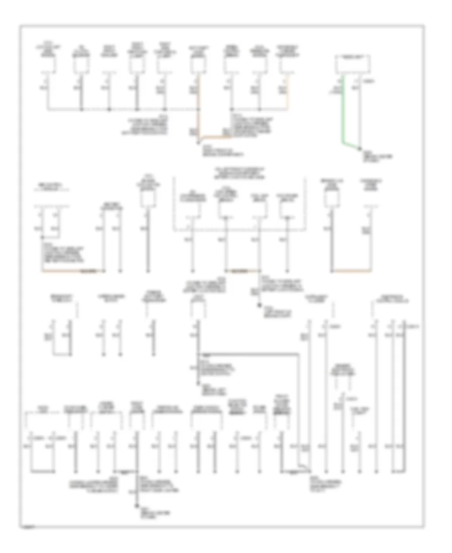
Ground Distribution Wiring Diagram (2 of 3) for Ford Escape 2003
 https://portal-diagnostov.com/license.html
Automotive Electricians Portal FZCO
Automotive Electricians Portal FZCO
https://portal-diagnostov.com/license.html
https://portal-diagnostov.com/license.html
Automotive Electricians Portal FZCO
Automotive Electricians Portal FZCOList of elements for Ground Distribution Wiring Diagram (2 of 3) for Ford Escape 2003:
- (2.0l)
- (3.0l)
- (3.0l) high speed fan control relay 2
- (on left front corner of engine compartment) battery junction box (bjb)
- A/c clutch solenoid
- A/c compressor clutch diode
- Abs control module
- Abs test connector
- Anti-theft hood switch
- Audio unit
- Brake fluid level switch
- Brake shift interlock
- C201a
- C2041a
- C220c
- C290a
- C290c
- C294c
- Dual pressure switch
- Engine cooling fan motor 1
- Fog lamp relay
- Four-wheel drive switch
- Front blower motor resistor assembly
- Front cigar lighter
- Fuel tank unit
- Function selector switch assembly
- G103 (right front of engine compartment)
- G104 (left front of engine compt)
- G201 (behind center of dash)
- G203 (behind left side of dash)
- G205 (behind center of dash)
- Generic electronic module (gem)
- Hazard flasher switch
- Instrument cluster
- Light switch
- Low coolant level switch
- Parking aid disable switch
- Passive anti-theft transceiver
- Pcm power relay
- Power point
- Rear window defrost switch
- Restraints control module
- Right front fog lamp
- Right front park/turn lamp
- Right side turn signal lamp
- S115 (in dash to headlamp junction harness, near breakout for anti-theft hood switch)
- S123 (in dash to headlamp junction harness, near breakout for abs test connector)
- S132 (in dash to headlamp junction harness, in battery junction box)
- S205 (in main harness, near breakout to c211)
- S233 (in radio jumper harness, near breakout to hazard flasher switch)
- Speed control servo
- Windshield washer pump motor
- Windshield wiper motor
- Wiper/washer switch
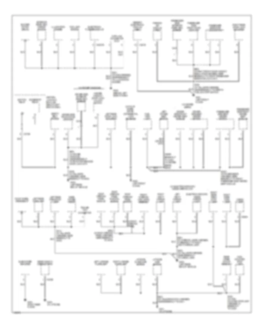
Ground Distribution Wiring Diagram (3 of 3) for Ford Escape 2003
 https://portal-diagnostov.com/license.html
Automotive Electricians Portal FZCO
Automotive Electricians Portal FZCO
https://portal-diagnostov.com/license.html
https://portal-diagnostov.com/license.html
Automotive Electricians Portal FZCO
Automotive Electricians Portal FZCOList of elements for Ground Distribution Wiring Diagram (3 of 3) for Ford Escape 2003:
- (near
- (w/ electrochromatic inside mirror unit)
- (w/ four- wheel drive)
- (w/ heated seats)
- (w/ power windows)
- Accessory relay
- Blower motor relay
- Breakout
- C201b
- C2027b
- C270e
- C402b
- C926a
- Cargo lamp
- Central junction box (cjb) (below left end of dash)
- Data link connector (dlc)
- Differential lock solenoid
- Driver side exterior rear view mirror
- Driver side front door lock unit
- Driver side front heated seat module
- Driver side seat heater switch
- Electrochromatic inside mirror unit
- Electronic flasher module
- Exterior rear view mirror switch
- Fog lamp switch
- Four-wheel drive relay
- Front interior/ map lamps assembly
- Fuel tank unit
- G202 (behind left side of dash)
- G300 (left front floor)
- G301 (left front floor)
- G400 (in liftgate)
- G401 (in liftgate)
- G402 (left rear end of vehicle)
- G403 (left rear end of vehicle)
- G404 (right rear floor)
- Generic electronic module (gem)
- High mounted stop lamp
- Ignition relay
- Illumination dimmer
- Left license plate lamp
- Left power seat switch
- Left rear door lock actuator
- Left rear park/stop lamp
- Left rear turn lamp
- Left vanity mirror lamp
- Liftgate ajar switch
- Liftgate glass ajar switch
- Master window/ door lock/ unlock switch
- Nca
- Parking aid module (pam)
- Passenger side door lock switch
- Passenger side exterior rear view mirror
- Passenger side front door lock unit
- Passenger side front heated seat module
- Passenger side seat heater switch
- Rear power point
- Rear window defrost grid
- Rear wiper motor assembly
- Right license plate lamp
- Right rear door lock actuator
- Right rear park/ stop lamp
- Right rear turn lamp
- Right vanity mirror lamp
- Roof opening panel module
- Roof opening panel position switch
- Roof opening panel switch
- S3001 (in power seats harness, near breakout to front passenger side heated seat module)
- S400 (in high mounted stoplamp harness, in breakout to c408)
- S500
- S902 (in roof opening panel harness, near breakout to c919)
- Safety belt switch
- Seats) s3000
- Subwoofer amplifier
- To c353) (w/ heated
- To front driver side door lock unit)
- Trailer tow connector
HEADLIGHTS
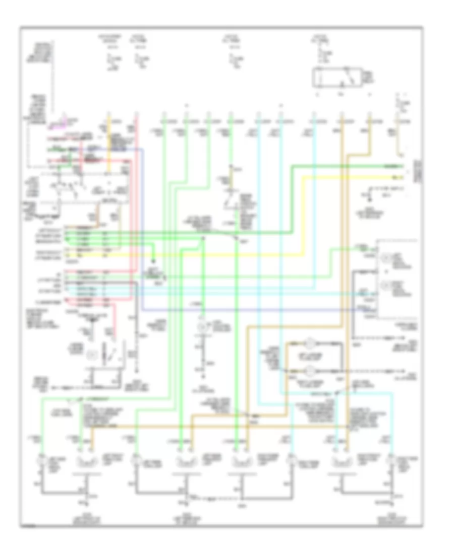
Headlights Wiring Diagram, with DRL for Ford Escape 2003
 https://portal-diagnostov.com/license.html
Automotive Electricians Portal FZCO
Automotive Electricians Portal FZCO
https://portal-diagnostov.com/license.html
https://portal-diagnostov.com/license.html
Automotive Electricians Portal FZCO
Automotive Electricians Portal FZCOList of elements for Headlights Wiring Diagram, with DRL for Ford Escape 2003:
- (in main harness, near breakout to ignition switch) s217
- (in main harness, near breakout to restraints control module) s2000
- 0 off 1 park 2 low beam 3 high beam 4 head 5 flash to pass
- 10a
- 15a
- 20a
- 87a
- Battery junction box (bjb) (on left front corner of engine compt)
- C201a
- C220a
- C220c
- C270a
- C270f
- Central junction box (cjb) (below left end of dash)
- Daytime running lamps (drl) module (behind lower left end of dash)
- Daytime running lamps (drl) relay (behind lower left end of dash)
- Electrochromatic inside mirror unit
- Fog lamp relay
- Fog lamp switch
- Fuse
- G103 (right front of engine compt)
- G104 (left front of engine compt)
- G105 (left front of engine compt)
- G202 (behind left side of dash)
- G203 (behind left side of dash)
- Generic electronic module (gem) (behind lower center of dash)
- Headlamp relay
- High beam
- Hot at all times
- Hot in start or run
- Illum
- Ind
- Instrument cluster
- Interior lights system
- Lamps module)
- Left front fog lamp
- Left headlamp
- Light switch
- Off
- Park brake switch (at base of park brake lever)
- Right front fog lamp
- Right headlamp
- S1000
- S115
- S117 (near breakout for left headlamp)
- S121 (in dash to headlamp junction harness, near breakout for left headlamp)
- S122 (near breakout for left headlamp)
- S131
- S133 (in dash to headlamp junction harness, in battery junction box)
- S134
- S140
- S142 (in dash to headlamp junction harness, near breakout for c260)
- S205
- S210 (in main harness, near breakout to ignition switch)
- S212
- S221
- W/ autolamps
Headlights Wiring Diagram, without DRL for Ford Escape 2003
 https://portal-diagnostov.com/license.html
Automotive Electricians Portal FZCO
Automotive Electricians Portal FZCO
https://portal-diagnostov.com/license.html
https://portal-diagnostov.com/license.html
Automotive Electricians Portal FZCO
Automotive Electricians Portal FZCOList of elements for Headlights Wiring Diagram, without DRL for Ford Escape 2003:
- (in main harness, near breakout to restraints control module) s2000
- (in main harness, near breakout to ignition switch) s211
- (in main harness, near breakout to ignition switch) s217
- 0 off 1 park 2 low beam 3 high beam 4 head 5 flash to pass
- 15a
- 20a
- Battery junction box (bjb) (on left front corner of engine compt)
- C201a
- C220a
- C220c
- Electrochromatic inside mirror unit
- Fog lamp relay
- Fog lamp switch
- Fuse
- G103 (right front of engine compt)
- G104 (left front of engine compt)
- G105 (left front of engine compt)
- G202 (behind left side of dash)
- G203 (behind left side of dash)
- Generic electronic module (gem) (behind lower center of dash)
- Headlamp relay
- High beam
- Hot at all times
- Illum
- Ind
- Instrument cluster
- Interior lights system
- Left front fog lamp
- Left headlamp
- Light switch
- Off
- Right front fog lamp
- Right headlamp
- S115
- S117 (in dash to headlamp junction harness, near breakout for left headlamp)
- S121 (in dash to headlamp junction harness, near breakout for left headlamp)
- S122 (in dash to headlamp junction harness, near breakout for left headlamp)
- S131
- S133 (in dash to headlamp junction harness, in battery junction box)
- S134
- S2001 (in main harness, near breakout to c211)
- S205
- S210 (in main harness, near breakout to ignition switch)
- S212
- S221
- W/ autolamps
HORN
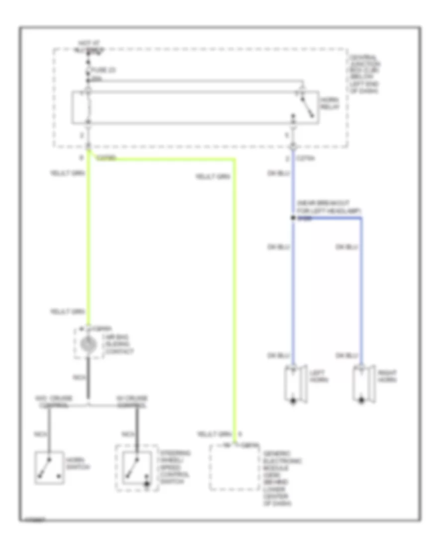
Horn Wiring Diagram for Ford Escape 2003
 https://portal-diagnostov.com/license.html
Automotive Electricians Portal FZCO
Automotive Electricians Portal FZCO
https://portal-diagnostov.com/license.html
https://portal-diagnostov.com/license.html
Automotive Electricians Portal FZCO
Automotive Electricians Portal FZCOList of elements for Horn Wiring Diagram for Ford Escape 2003:
- (near breakout
- 20a
- Air bag sliding contact
- C201a
- C218a
- C270a
- C270d
- Central junction box (cjb) (below left end of dash)
- For left headlamp) s120
- Fuse 23
- Generic electronic module (gem) (behind lower center of dash)
- Horn relay
- Horn switch
- Hot at all times
- Left horn
- Nca
- Right horn
- Steering wheel/ speed control switch
- W/ cruise control
- W/o cruise control
INSTRUMENT CLUSTER
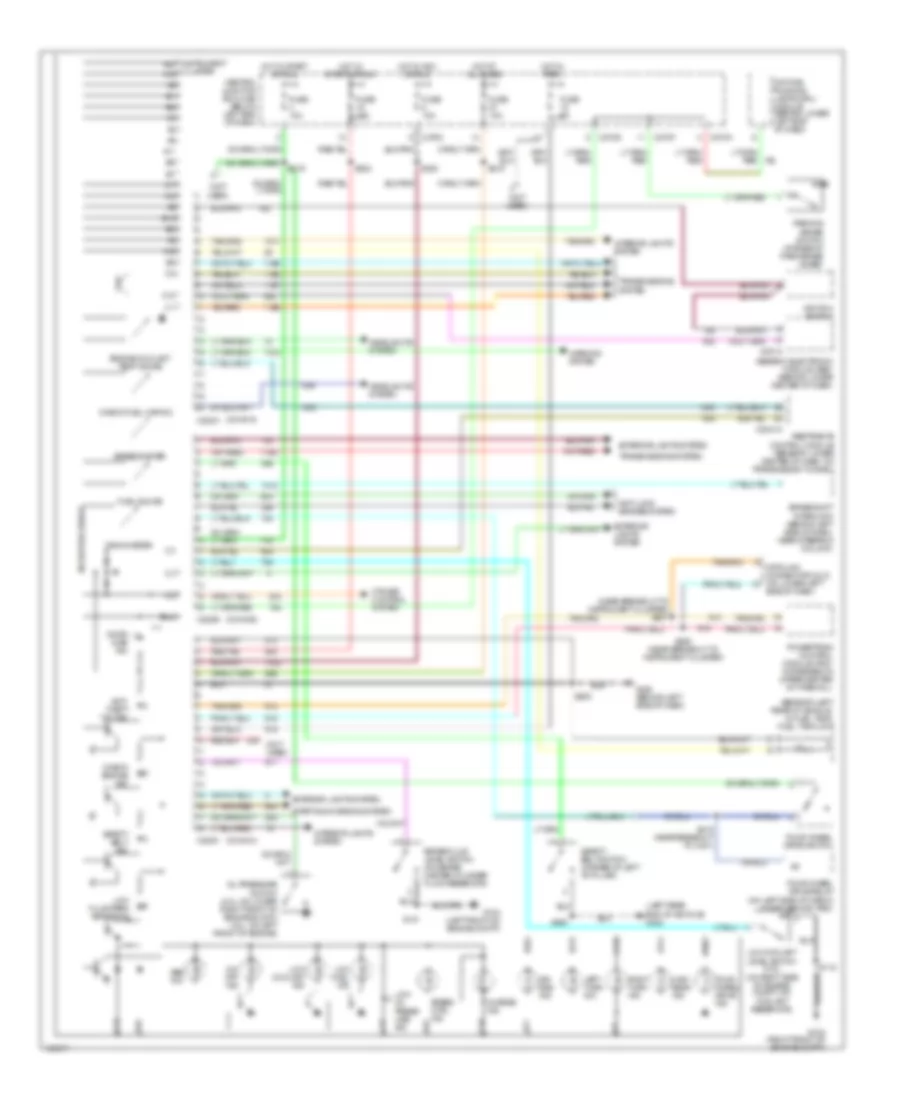
Instrument Cluster Wiring Diagram for Ford Escape 2003
 https://portal-diagnostov.com/license.html
Automotive Electricians Portal FZCO
Automotive Electricians Portal FZCO
https://portal-diagnostov.com/license.html
https://portal-diagnostov.com/license.html
Automotive Electricians Portal FZCO
Automotive Electricians Portal FZCOList of elements for Instrument Cluster Wiring Diagram for Ford Escape 2003:
- (beneath left rear of vehicle, in fuel tank) fuel tank unit
- (conn a)
- (conn b)
- (conn c)
- (left rear end of vehicle) g402
- (near breakout to instrument cluster) s207
- (not used)
- A10
- A11
- A14
- A16
- Abs ind
- Air bag ind
- Anti- theft "on" ind
- Anti-lock brakes system
- B10
- B11
- B12
- B13
- B15
- B16
- Brake fluid level switch (on brake master cylinder fluid reservoir)
- Brake shift interlock (behind left side of dash, near steering column)
- C12
- C15
- C16
- C17
- C18
- C201a
- C2041a
- C220a
- C220b
- C220c
- C270a
- C270c
- C270d
- C270f
- Central junction box (cjb) (below left end of dash)
- Charge ind
- Check engine ind
- Check fuel cap ind
- Cluster a15
- Coolant reservoir)
- Cruise control system
- Data link connector (dlc) (on lower left
- Daytime running lamps (drl) module (behind lower left end of dash)
- Door ajar ind
- Engine coolant temp gauge
- Exterior lights system
- Four- wheel drive ind
- Four-wheel drive relay (on left side of cargo compt, behind trim)
- Four-wheel drive switch
- Fuel gauge
- Fuse 10a
- Fuse 5a
- G103 (right front of engine compt)
- G104 (left front of engine compt)
- G203 (behind left side of dash)
- Generic electronic module (gem) (behind lower center of dash)
- Headlights system
- High beam ind
- Hot at all times
- Hot in acc or run
- Hot in park
- Hot in start or run
- Ignition switch
- Instrument a20
- Interior lights system
- Left turn ind
- Low coolant ind
- Low coolant level switch (3.0l) (on right side of engine compt, on
- Low fluid/park brake ind
- Low fuel ind
- Low oil press- ure ind
- Microprocessor
- O/d off ind
- Oil pressure switch (2.0l: on lower right front of engine block) (3.0l: on left front of engine)
- Parking brake switch (at base of park brake lever)
- Powertrain control module (pcm) (in recess on upper center of firewall)
- Restraints control module (beneath lower center of dash, on transmission tunnel)
- Right turn ind
- S115
- S131
- S205
- S206 (near breakout to instrument cluster)
- S215
- S216
- S220
- S222
- S309
- S415 (near breakout to c421)
- Safety belt ind
- Safety belt switch (at base of left "b" pillar)
- Side of dash)
- Speed ctrl ind
- Speedometer
- Starting/charging system
- Tachometer
- Transmissions system
- Warning system
INTERIOR LIGHTS
Courtesy Lamps Wiring Diagram for Ford Escape 2003
 https://portal-diagnostov.com/license.html
Automotive Electricians Portal FZCO
Automotive Electricians Portal FZCO
https://portal-diagnostov.com/license.html
https://portal-diagnostov.com/license.html
Automotive Electricians Portal FZCO
Automotive Electricians Portal FZCOList of elements for Courtesy Lamps Wiring Diagram for Ford Escape 2003:
- (left rear end of vehicle) g403
- C201a
- C201b
- C220a
- C270c
- C270d
- C270e
- C926a
- C926b
- Cargo lamp
- Central junction box (cjb) (below left end of dash)
- Door
- Driver side front door lock unit (ajar switch)
- Electro- chromatic inside mirror unit
- Front interior lamp
- Front interior/ map lamps assembly (w/ roof opening panel) 1: door 2: off 3: on
- Fuse 10a
- Fuse 30a
- G201 (behind center of dash)
- G300 (left front floor)
- G301 (left front floor)
- G401 (in liftgate)
- G403 (left rear end of vehicle)
- Generic electronic module (behind lower center of dash)
- Hot at all times
- Hot in run or acc
- Hot in start or run
- Inside mirror unit
- Instrument cluster
- Left rear door lock actuator (ajar switch)
- Left vanity mirror lamp
- Liftgate ajar switch (on top center of liftgate)
- Liftgate glass ajar switch
- Map lamps
- Off
- Passenger side front door lock unit (ajar switch)
- Right rear door lock actuator (ajar switch)
- Right vanity mirror lamp
- S2002 (near breakout to evap canister vent control solenoid)
- S205
- S216
- S220
- S222
- S302
- S309
- S311
- S401
- S403
- S404 (in taillamps harness, near breakout to cargo lamp)
- S405 (in taillamps harness, near breakout to cargo lamp)
- S500
- S600
- S900 (in interior lamps harness, in breakout to right vanity mirror lamp)
- S901
- S903 (in interior lamps harness, in breakout to front interior lamp)
- W/ electrochromatic
- W/ roof opening panel
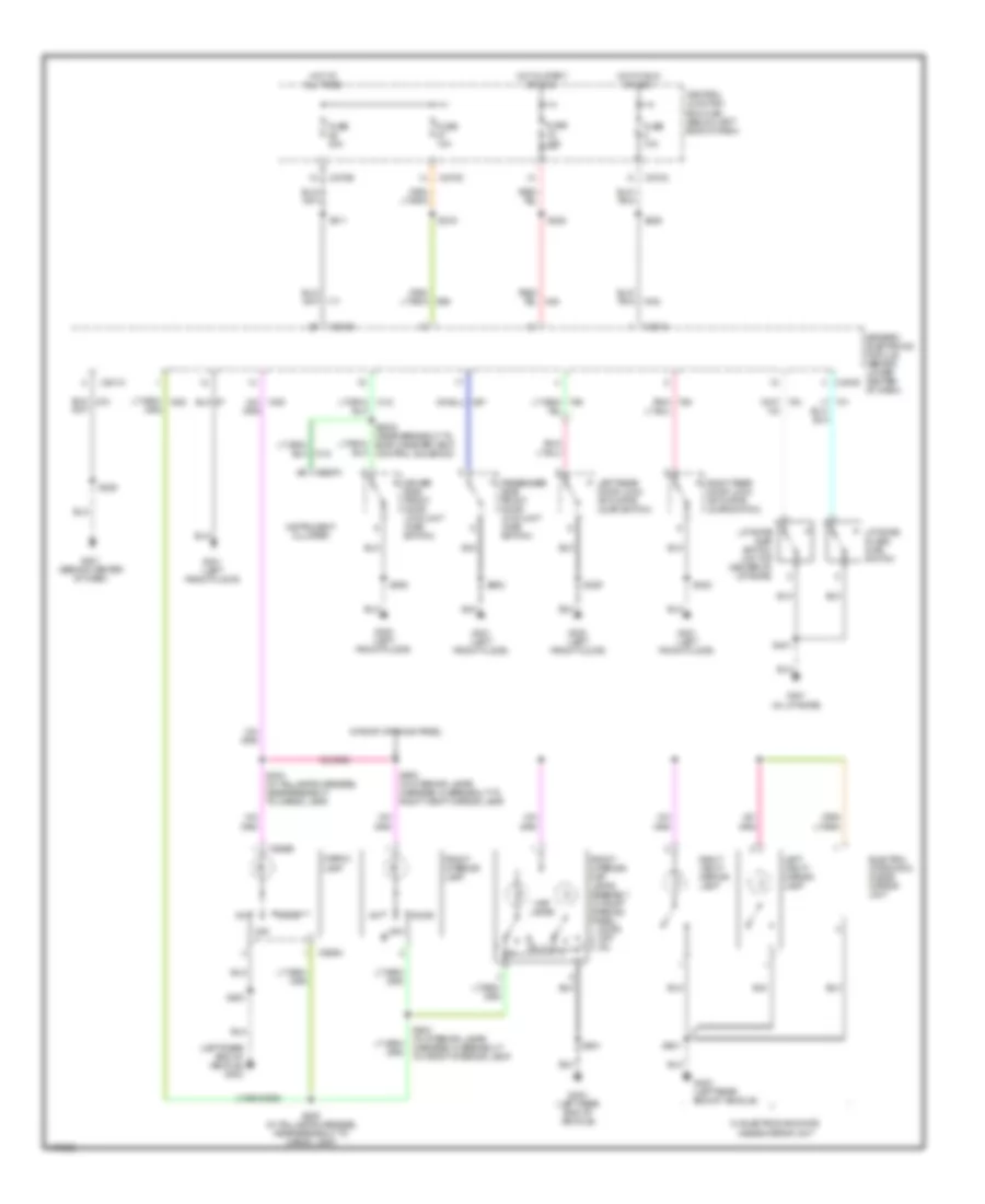
Instrument Illumination Wiring Diagram for Ford Escape 2003
 https://portal-diagnostov.com/license.html
Automotive Electricians Portal FZCO
Automotive Electricians Portal FZCO
https://portal-diagnostov.com/license.html
https://portal-diagnostov.com/license.html
Automotive Electricians Portal FZCO
Automotive Electricians Portal FZCOList of elements for Instrument Illumination Wiring Diagram for Ford Escape 2003:
- (not used)
- Audio unit
- Brighter
- C201a
- C220a
- C220c
- C270d
- C290a
- C294c
- Central junction box (cjb) (below left end of dash)
- Dimmer
- Fog lamp switch
- Four- wheel drive switch
- Function selector switch assembly
- Fuse 15a
- Fuse 5a
- G201 (behind center of dash)
- G202 (behind left side of dash)
- G203 (behind left side of dash)
- Generic electronic module (behind lower center of dash)
- Hazard flasher switch
- Head
- Hot at all times
- Illumination dimmer
- Instrument cluster
- Light switch
- Micro- processor
- Off
- Park
- Park lamp relay
- Parking aid disable switch
- Rear window defrost switch
- S2001 (in main harness, near breakout to c211)
- S203
- S212
- S221
- S231 (in radio jumper harness, near breakout to c210)
- S233
- Tan/
NAVIGATION
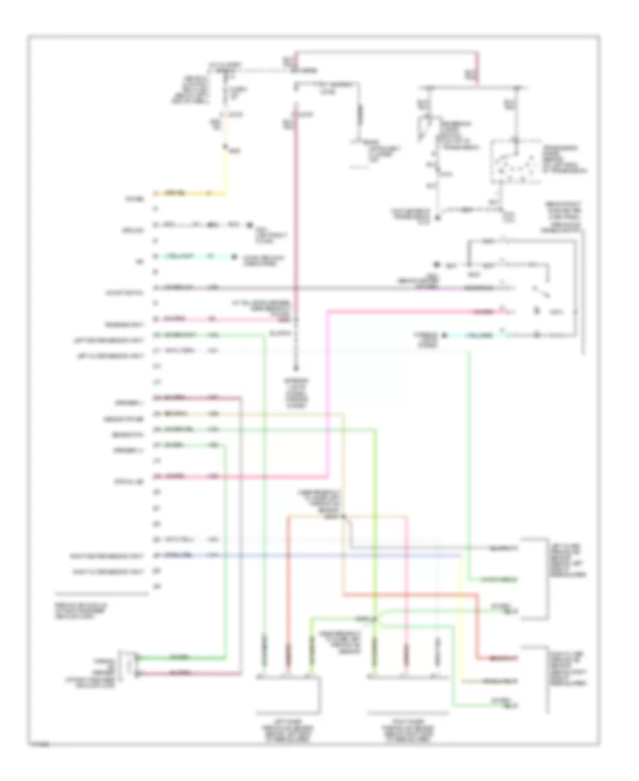
Parking Assistant Wiring Diagram for Ford Escape 2003
 https://portal-diagnostov.com/license.html
Automotive Electricians Portal FZCO
Automotive Electricians Portal FZCO
https://portal-diagnostov.com/license.html
https://portal-diagnostov.com/license.html
Automotive Electricians Portal FZCO
Automotive Electricians Portal FZCOList of elements for Parking Assistant Wiring Diagram for Ford Escape 2003:
- (at right side rear vehicle floor)
- (behind right
- (in taillamps harness, near breakout to g402)
- (near breakout to inner left parking aid sensor)
- (top center of transmission) g101
- A/t
- C220b
- C270b
- C270d
- C270f
- Central junction box (cjb) (below left end of dash)
- Computer data lines system
- Dash panel)
- Exterior lights system, mirrors system
- Fuse 6 10a
- G201 (behind center of dash)
- G301 (left front floor)
- Ground
- Hot in start or run
- Instrument cluster (a/t)
- Interior lights system
- Iso
- Left center sensor input
- Left inner parking aid sensor (behind left side of rear bumper)
- Left outer parking aid sensor (behind left side of rear bumper)
- Left outer sensor input
- M/t
- On/off switch
- Parking aid disable switch
- Parking aid module (at right side rear vehicle floor)
- Parking aid speaker
- Power
- Reverse input
- Reversing lamps switch (on top of transmission)
- Right center sensor input
- Right inner parking aid sensor (behind right side of rear bumper)
- Right outer parking aid sensor (behind right side of rear bumper)
- Right outer sensor input
- S104
- S104 (2.0l)
- S203
- S302
- S4000
- S4001
- S408
- S409
- Sensor power
- Sensor rtn
- Side center
- Speaker (+)
- Speaker (-)
- Status led
- Transmission range sensor (on left side of transmission)
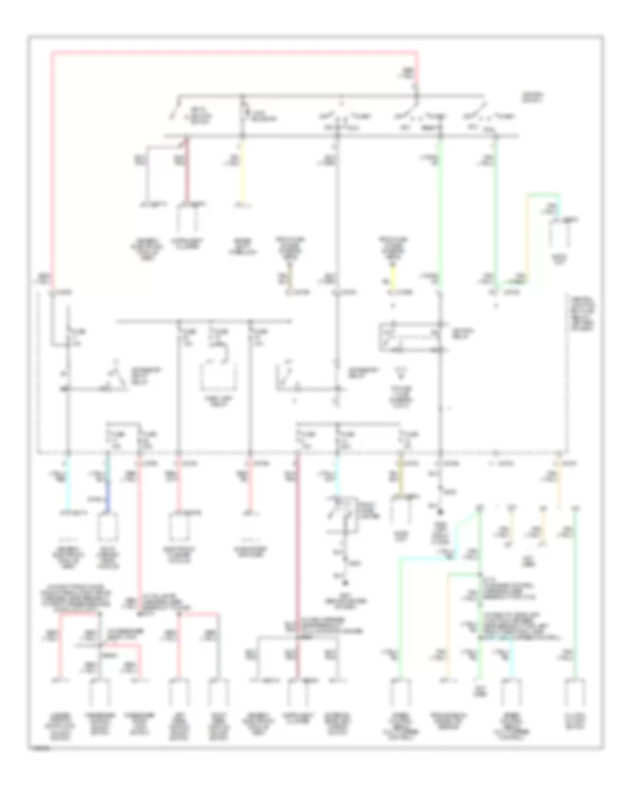
POWER DISTRIBUTION
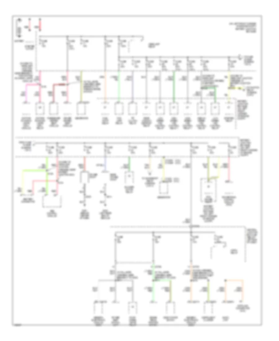
Power Distribution Wiring Diagram (1 of 3) for Ford Escape 2003
 https://portal-diagnostov.com/license.html
Automotive Electricians Portal FZCO
Automotive Electricians Portal FZCO
https://portal-diagnostov.com/license.html
https://portal-diagnostov.com/license.html
Automotive Electricians Portal FZCO
Automotive Electricians Portal FZCOList of elements for Power Distribution Wiring Diagram (1 of 3) for Ford Escape 2003:
- (2.0l) (3.0l)
- (3.0l) (2.0l)
- (in dash to headlamp junction harness, near breakout for daytime running lamps module)
- (in dash to headlamp red
- (in taillamps harness, near breakout to parking brake switch)
- (on left front corner of engine compt) battery junction box (bjb)
- A/c clutch relay
- Abs control module
- Abs test connector
- Audio unit
- Battery
- Battery junction box (bjb) (on left front corner of engine compt)
- Blower motor relay
- Brake pedal position switch
- C102a
- C102c c102b
- C1035c c1035b
- C201a
- C201b
- C220c
- C270b
- C270d
- C270e
- C290a
- Central junction box (cjb) (below left end of dash)
- Data link connector (dlc)
- Daytime running lamps (drl) module
- Daytime running lamps (drl) relay
- Deactivator switch
- Driver heated seat module
- Fog lamp relay
- Four- wheel drive relay
- From fuse 19 (bjb) (diagram 1 of 3)
- Fuel pump relay
- Fuse 10a
- Fuse 15a
- Fuse 20a
- Fuse 25a
- Fuse 30a
- Fuse 30a (3.0l)
- Fuse 40a
- Fuse 40a (2.0l)
- Fuse 50a (3.0l)
- Fuse 5a
- Fuse 60a
- Fuse b 120a
- G201 (behind center of dash)
- G403 (left rear end of vehicle)
- Generator
- Generic electronic module (gem)
- Headlamp relay
- High speed fan control relay 1
- Horn relay
- Instrument cluster
- Junction harness, near battery junction box)
- Low speed fan control relay
- Medium speed fan control relay
- Near breakout to passive anti-theft transceiver) s216
- Passenger heated seat module
- Pcm power relay
- Power point
- Power seat switch left
- Powertrain control module (pcm)
- Rear power point
- Rear window defrost relay
- Red
- S124
- S126
- S140
- S203
- S3002
- S414
- Starter motor
- Starter relay
- To accessory relay (diagram 2 of 3)
- To fuse 24 (bjb) (diagram 1 of 3)
- To ignition relay (diagram 2 of 3)
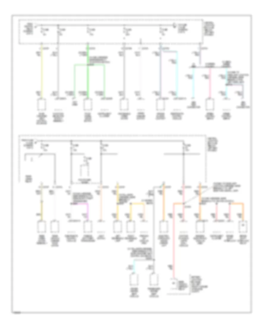
Power Distribution Wiring Diagram (2 of 3) for Ford Escape 2003
 https://portal-diagnostov.com/license.html
Automotive Electricians Portal FZCO
Automotive Electricians Portal FZCO
https://portal-diagnostov.com/license.html
https://portal-diagnostov.com/license.html
Automotive Electricians Portal FZCO
Automotive Electricians Portal FZCOList of elements for Power Distribution Wiring Diagram (2 of 3) for Ford Escape 2003:
- (2.0l w/ speed control)
- (in dash to headlamp junction harness, near breakout for left front park/turn lamp) s137
- (in main harness, near breakout to illumination dimmer) s220
- (in right front door window regulator wiring harness, near breakout to front passenger side door lock unit)
- (in taillamps harness, near breakout to g300) s310
- A/t
- Acc
- Accessory delay relay
- Accessory relay
- Audio unit
- Brake shift interlock
- Breakout for c134)
- C201a
- C2027b
- C220a
- C220c
- C270a
- C270b
- C270c
- C270d
- C270e
- C270f
- C290a
- Central junction box (cjb) (below left end of dash)
- Clutch cutoff switch
- Electronic flasher module
- Exterior rear view mirror switch
- From fuse 19 (bjb) (diagram 1 of 3)
- From fuse 20 (bjb) (diagram 1 of 3)
- Front cigar lighter
- Fuse 10a
- Fuse 15a
- Fuse 20a
- Fuse 30a
- Fuse 5a
- G201 (behind center of dash)
- G300 (left front floor)
- Generic electronic module (gem)
- Ignition relay
- Ignition switch
- Instrument cluster
- Key in ignition switch
- Left rear window adjust switch
- Lock solenoid
- M/t
- Master window/ door lock/ unlock switch
- Not used
- Off
- Park lamp relay
- Passenger door lock switch
- Passenger window adjust switch
- Right rear window adjust switch
- Roof opening panel module
- Run
- S203
- S309
- S6000
- Speed control servo (2.0l w/ speed control)
- Speed control servo (3.0l w/ speed control)
- Start
- Subwoofer amplifier
- To fuse 1 (cjb) (diagram 3 of 3)
- Transmission range (tr) sensor
- W/ passenger door lock
Power Distribution Wiring Diagram (3 of 3) for Ford Escape 2003
 https://portal-diagnostov.com/license.html
Automotive Electricians Portal FZCO
Automotive Electricians Portal FZCO
https://portal-diagnostov.com/license.html
https://portal-diagnostov.com/license.html
Automotive Electricians Portal FZCO
Automotive Electricians Portal FZCOList of elements for Power Distribution Wiring Diagram (3 of 3) for Ford Escape 2003:
- (in dash to headlamp junction harness, near breakout to left side turn signal lamp)
- (in main harness, near breakout to ignition switch) s215
- (in main harness, near breakout to ignition switch) s222
- (in taillamps harness, near breakout to evap canister vent control solenoid) s3003
- Abs test connector
- Air bag sliding contact
- Battery junction box (bjb) (on left front corner of engine compt)
- Brake shift interlock
- Brake shift interlock relay
- C201a
- C2041a
- C218a
- C220b
- C220c
- C270a
- C270b
- C270c
- C270d
- C270f
- C294a
- Central junction box (cjb) (below left end of dash)
- Daytime running lamps (drl) module
- Driver heated seat module
- Electro- chromatic inside mirror unit
- Evap canister vent control solenoid
- Four- wheel drive switch
- From fuse 5 (cjb) (diagram 3 of 3)
- From ignition d
- Function selector switch assembly
- Fuse 10a
- Fuse 20a
- Fuse 3a
- Fuse 5a
- Generic electronic module (gem)
- Instrument cluster
- Left reversing lamp
- Light switch
- Not used
- Parking aid module (pam)
- Passenger heated seat module
- Passive anti-theft transceiver
- Pcm power diode
- Rear window defrost relay
- Rear window washer pump motor
- Rear wiper motor assembly
- Rear wiper relay
- Relay (diagram 2 of 3)
- Restraints control module
- Right reversing lamp
- S1000
- Speed control servo
- To fuse 3 (cjb) (diagram 3 of 3)
- W/ abs
- W/ abs & speed control
- W/ heated seats
- W/ speed control
- Windshield wiper motor
- Wiper/ washer switch
POWER MIRRORS
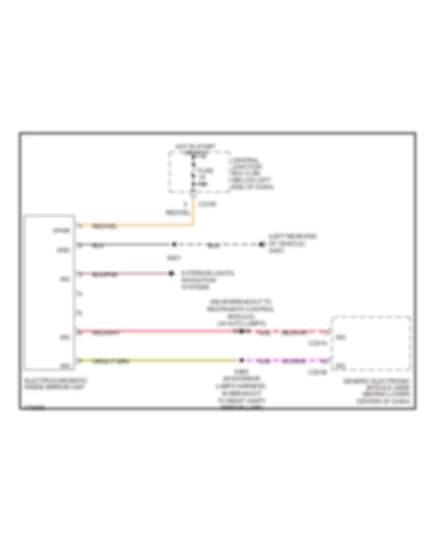
Electronic Day/Night Mirror Wiring Diagram for Ford Escape 2003
 https://portal-diagnostov.com/license.html
Automotive Electricians Portal FZCO
Automotive Electricians Portal FZCO
https://portal-diagnostov.com/license.html
https://portal-diagnostov.com/license.html
Automotive Electricians Portal FZCO
Automotive Electricians Portal FZCOList of elements for Electronic Day/Night Mirror Wiring Diagram for Ford Escape 2003:
- (left rear end of vehicle) g403
- (near breakout to restraints control module) (w/ auto lamps) s2000
- C201a
- C201b
- C270f
- Central junction box (cjb) (below left end of dash)
- Electrochromatic inside mirror unit
- Exterior lights, navigation systems
- Fuse 10a
- Generic electronic module (gem) (behind lower center of dash)
- Gnd
- Hot in start or run
- S900 (in interior lamps harness, in breakout to right vanity mirror lamp)
- S901
- Sig
- Vpwr
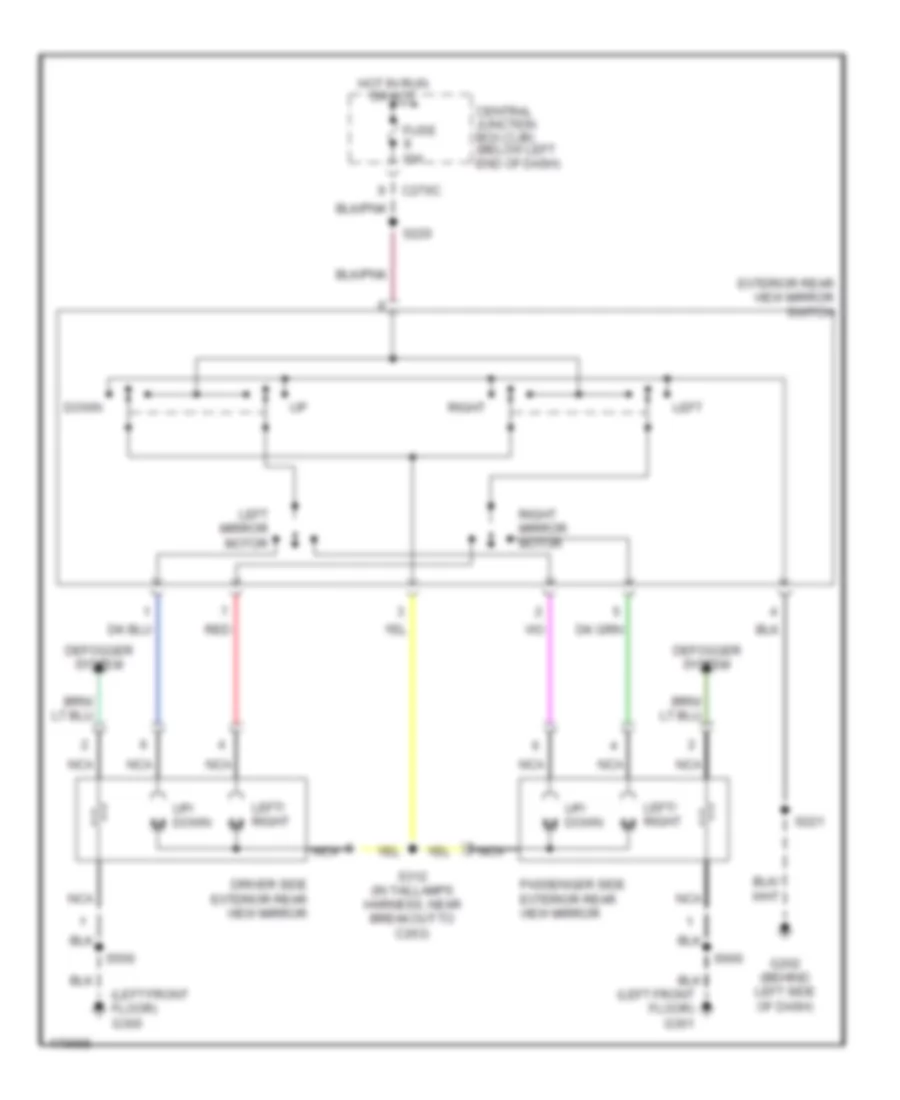
Power Mirrors Wiring Diagram for Ford Escape 2003
 https://portal-diagnostov.com/license.html
Automotive Electricians Portal FZCO
Automotive Electricians Portal FZCO
https://portal-diagnostov.com/license.html
https://portal-diagnostov.com/license.html
Automotive Electricians Portal FZCO
Automotive Electricians Portal FZCOList of elements for Power Mirrors Wiring Diagram for Ford Escape 2003:
- (left front floor) g300
- C270c
- Central junction box (cjb) (below left end of dash)
- Defogger system
- Down
- Driver side exterior rear view mirror
- Exterior rear view mirror switch
- Fuse 10a
- G202 (behind left side of dash)
- Hot in run or acc
- Left
- Left mirror motor
- Left/ right
- Nca
- Passenger side exterior rear view mirror
- Red
- Right
- Right mirror motor
- S220
- S221
- S312 (in taillamps harness, near breakout to c263)
- S500
- S600
- Up/ down m
POWER SEATS
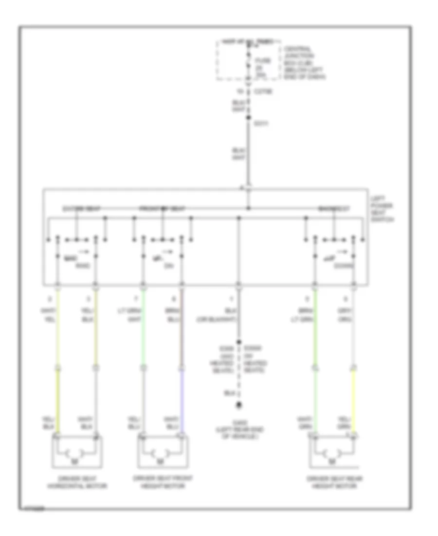
Driver Seat Wiring Diagram for Ford Escape 2003
 https://portal-diagnostov.com/license.html
Automotive Electricians Portal FZCO
Automotive Electricians Portal FZCO
https://portal-diagnostov.com/license.html
https://portal-diagnostov.com/license.html
Automotive Electricians Portal FZCO
Automotive Electricians Portal FZCOList of elements for Driver Seat Wiring Diagram for Ford Escape 2003:
- (w/ heated seats)
- (w/o heated seats)
- Backrest
- C270e
- Central junction box (cjb) (below left end of dash)
- Down
- Driver seat front height motor
- Driver seat horizontal motor
- Driver seat rear height motor
- Entire seat
- Front of seat
- Fuse 30a
- Fwd
- G402 (left rear end of vehicle)
- Hot at all times
- Left power seat switch
- Rwd
- S3000
- S309
- S311
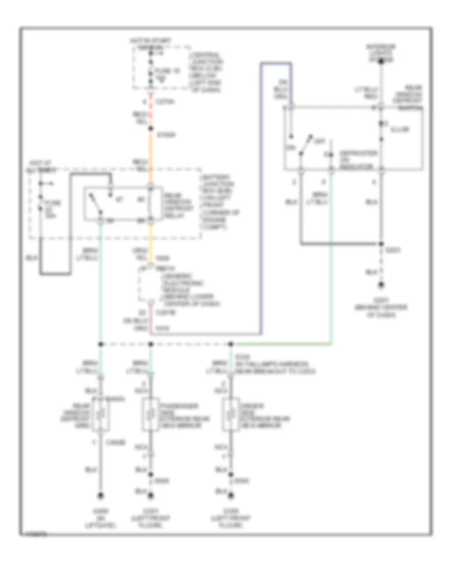
Heated Seats Wiring Diagram for Ford Escape 2003
 https://portal-diagnostov.com/license.html
Automotive Electricians Portal FZCO
Automotive Electricians Portal FZCO
https://portal-diagnostov.com/license.html
https://portal-diagnostov.com/license.html
Automotive Electricians Portal FZCO
Automotive Electricians Portal FZCOList of elements for Heated Seats Wiring Diagram for Ford Escape 2003:
- Battery junction box (bjb) (on left front corner of engine compt)
- Breakout to parking brake switch)
- C270f
- Central junction box (cjb) (below left end of dash)
- Driver side front heated seat module (under driver's seat)
- Driver side seat heater switch
- Fuse 16 10a
- Fuse 9 30a
- G300 (left front floor)
- Hot at all times
- Hot in start or run
- Left front seat back heater
- Left front seat cushion heater
- Nca
- On off
- Passenger side front heated seat module (under passenger's seat)
- Passenger side seat heater switch
- Red
- Right front seat back heater
- Right front seat cushion heater
- S3000
- S3001
- S3003 (in taillamps harness, near breakout to evap canister vent control solenoid)
POWER TOP/SUNROOF
Power Top/Sunroof Wiring Diagram for Ford Escape 2003
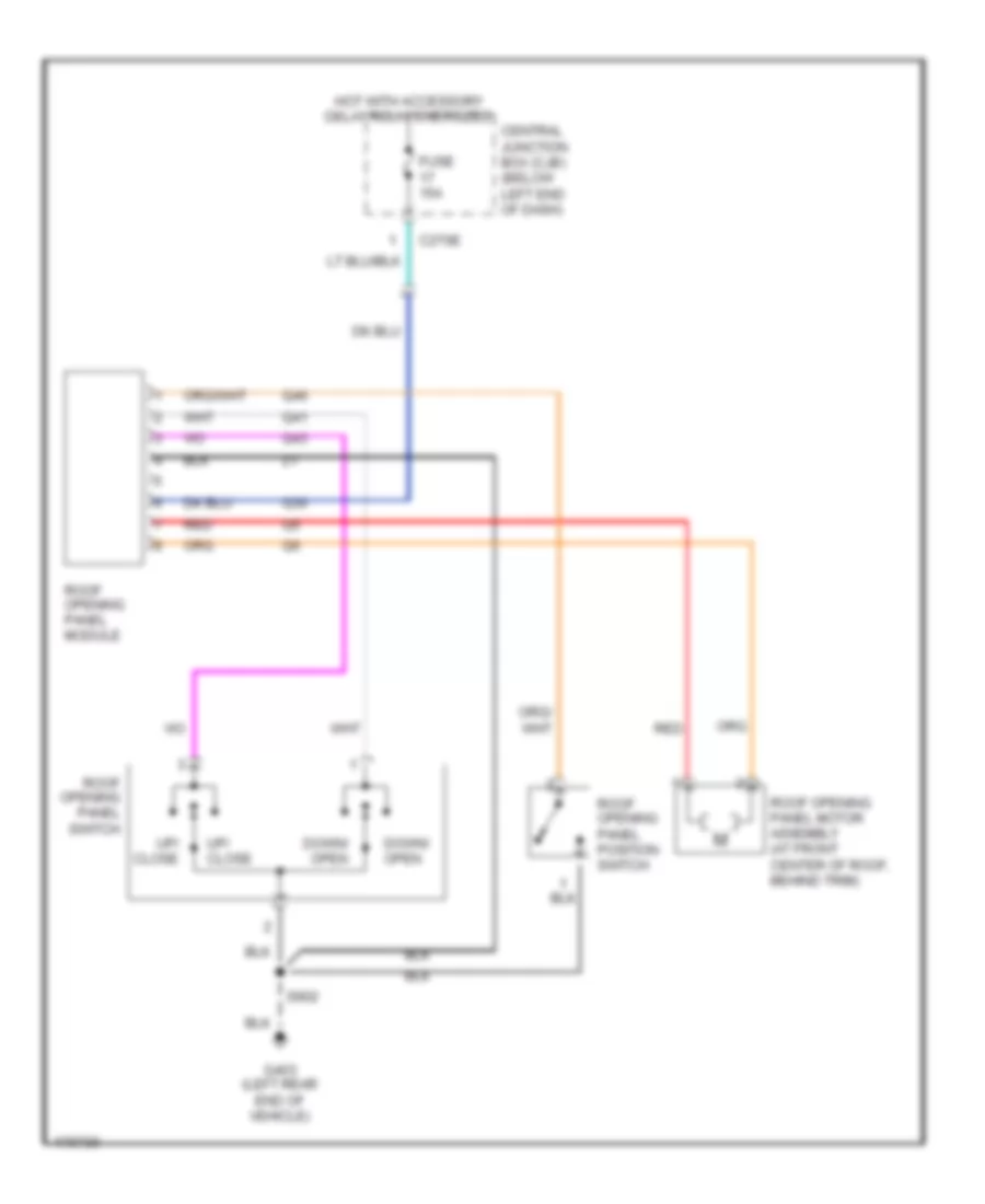 https://portal-diagnostov.com/license.html
Automotive Electricians Portal FZCO
Automotive Electricians Portal FZCO
https://portal-diagnostov.com/license.html
https://portal-diagnostov.com/license.html
Automotive Electricians Portal FZCO
Automotive Electricians Portal FZCOList of elements for Power Top/Sunroof Wiring Diagram for Ford Escape 2003:
- C270e
- Central junction box (cjb) (below left end of dash)
- Down/ open
- Fuse 15a
- G403 (left rear end of vehicle)
- Hot with accessory delay relay energized
- Q30
- Q41
- Q43
- Q46
- Red
- Roof opening panel module
- Roof opening panel motor assembly (at front center of roof, behind trim)
- Roof opening panel position switch
- Roof opening panel switch
- S902
- Up/ close
POWER WINDOWS
Power Windows Wiring Diagram for Ford Escape 2003
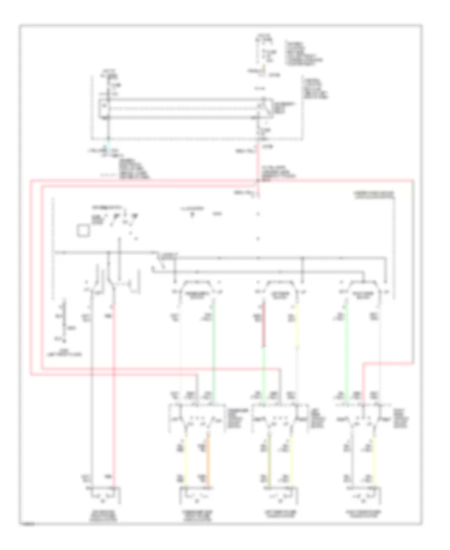 https://portal-diagnostov.com/license.html
Automotive Electricians Portal FZCO
Automotive Electricians Portal FZCO
https://portal-diagnostov.com/license.html
https://portal-diagnostov.com/license.html
Automotive Electricians Portal FZCO
Automotive Electricians Portal FZCOList of elements for Power Windows Wiring Diagram for Ford Escape 2003:
- (in taillamps harness, near breakout to g300) s310
- 10a
- 30a
- 40a
- Accessory delay relay
- Battery junction box (bjb) (on left front corner of engine compartment)
- C201a
- C270b
- C270e
- Central junction box (cjb) (below left end of dash)
- Driver side front power window motor
- Driver's switch
- Fuse
- G300 (left front floor)
- Generic electronic module (gem) (behind lower center of dash)
- Hot at all times
- Illumination
- Left rear power window motor
- Left rear switch
- Left rear window adjust switch
- Lockout switch
- Master window/door lock/unlock switch
- Off
- One- touch down
- Passenger side front power window motor
- Passenger side window adjust switch
- Passenger's switch
- Red
- Rest
- Right rear power window motor
- Right rear switch
- Right rear window adjust switch
- S500
RADIO
Base Radio Wiring Diagram for Ford Escape 2003
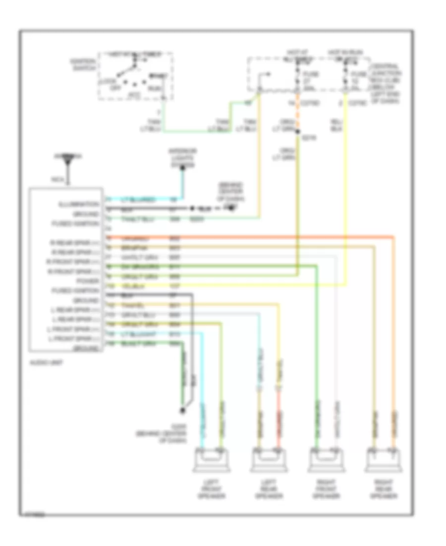 https://portal-diagnostov.com/license.html
Automotive Electricians Portal FZCO
Automotive Electricians Portal FZCO
https://portal-diagnostov.com/license.html
https://portal-diagnostov.com/license.html
Automotive Electricians Portal FZCO
Automotive Electricians Portal FZCOList of elements for Base Radio Wiring Diagram for Ford Escape 2003:
- (behind center of dash) g201
- Acc
- Antenna
- Audio unit
- C270c
- C270d
- Central junction box (cjb) (below left end of dash)
- Fuse 10a
- Fuse 5a
- Fused ignition
- G205 (behind center of dash)
- Ground
- Hot at all times
- Hot in run or acc
- Ignition switch
- Illumination
- Interior lights system
- L front spkr (+)
- L front spkr (-)
- L rear spkr (+)
- L rear spkr (-)
- Left front speaker
- Left rear speaker
- Lock
- Nca
- Off
- Power
- R front spkr (+)
- R front spkr (-)
- R rear spkr (+)
- R rear spkr (-)
- Right front speaker
- Right rear speaker
- Run
- S216
- S233
- Start
Premium Sound Radio Wiring Diagram for Ford Escape 2003
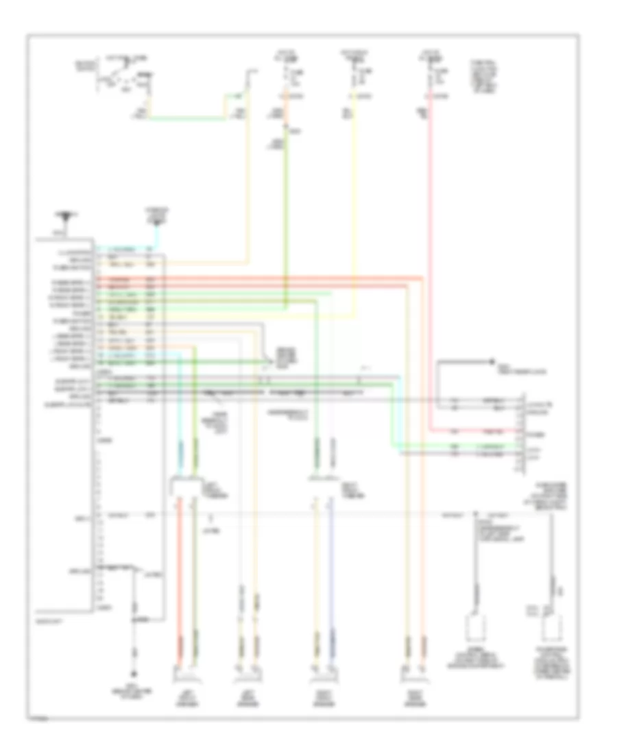 https://portal-diagnostov.com/license.html
Automotive Electricians Portal FZCO
Automotive Electricians Portal FZCO
https://portal-diagnostov.com/license.html
https://portal-diagnostov.com/license.html
Automotive Electricians Portal FZCO
Automotive Electricians Portal FZCOList of elements for Premium Sound Radio Wiring Diagram for Ford Escape 2003:
- (2.0l)
- (3.0l)
- (behind center of dash) g205
- (near breakout to audio unit)
- (near breakout to c213)
- Acc
- Antenna
- Audio unit
- C270c
- C270d
- C270e
- C290a
- C290b
- C290c
- Central junction box (cjb) (below left end of dash)
- Fuse 10a
- Fuse 5a
- Fused ignition
- G201 (behind center of dash)
- G404 (right rear floor)
- Ground
- Hot at all times
- Hot in run or acc
- Ignition switch
- Illumination
- Interior lights system
- L front spkr (+)
- L front spkr (-)
- L rear spkr (+)
- L rear spkr (-)
- Left front speaker
- Left front tweeter
- Left rear speaker
- Limited
- Lock
- Low +
- Low -
- Low mute
- Nca
- Off
- Power
- Powertrain control module (pcm) (in recess on upper center of firewall)
- R front spkr (+)
- R front spkr (-)
- R rear spkr (+)
- R rear spkr (-)
- Right front speaker
- Right front tweeter
- Right rear speaker
- Run
- S1002 (near breakout to left side turn signal lamp)
- S216
- S230
- S233
- S234
- Speed control servo (on right side of engine compartment)
- Start
- Subwfr low +
- Subwfr low -
- Subwfr low mute
- Subwoofer amplifier (on right side of cargo compt, behind trim)
- Vss (+)
SHIFT INTERLOCK
Shift Interlock Wiring Diagram for Ford Escape 2003
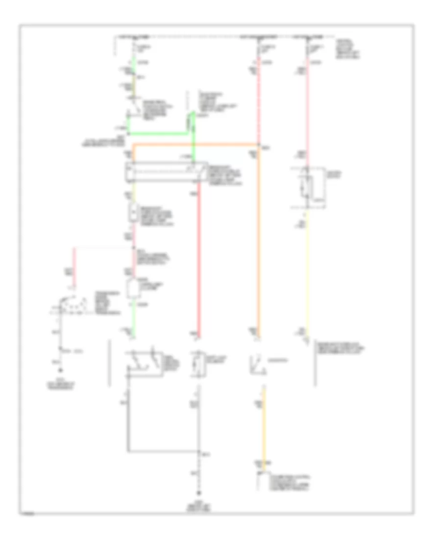 https://portal-diagnostov.com/license.html
Automotive Electricians Portal FZCO
Automotive Electricians Portal FZCO
https://portal-diagnostov.com/license.html
https://portal-diagnostov.com/license.html
Automotive Electricians Portal FZCO
Automotive Electricians Portal FZCOList of elements for Shift Interlock Wiring Diagram for Ford Escape 2003:
- (2.0l)
- Brake pedal position switch (on bracket, above brake pedal)
- Brake shift interlock diode (behind left side of dash, near steering column)
- Brake shift interlock (behind left side of dash, near steering column)
- Brake shift interlock relay (behind left side of dash, near steering column)
- C2027a
- C220b
- C270c
- C270d
- C270e
- Central junction box (cjb) (behind left end of dash)
- Electronic flasher module (behind lower left end of dash)
- Fuse 11 10a
- Fuse 16 10a
- Fuse 24 15a
- G101 (top center of transmission)
- G203 (behind left side of dash)
- Hot at all times
- Hot in run or start
- Ignition switch
- Instrument cluster
- Lock
- O/d switch
- Park neutral position switch
- Powertrain control module (pcm) (in recess on upper center of firewall)
- Red
- S104
- S212
- S218 (in main harness, near breakout to ignition switch)
- S222
- S314
- S407 (in taillamps harness, near breakout to g402)
- Shift lock solenoid
- Transmission range sensor (on left side of transmission)
STARTING/CHARGING
Starting Wiring Diagram for Ford Escape 2003
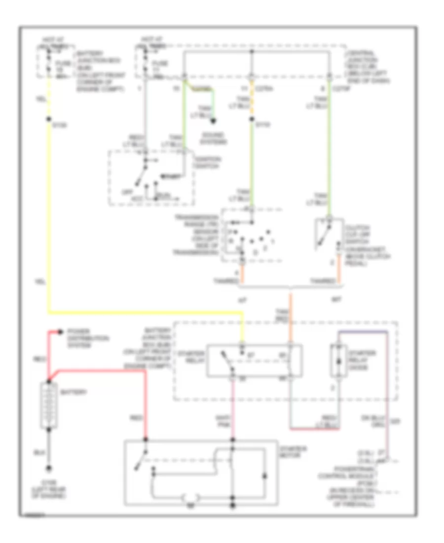 https://portal-diagnostov.com/license.html
Automotive Electricians Portal FZCO
Automotive Electricians Portal FZCO
https://portal-diagnostov.com/license.html
https://portal-diagnostov.com/license.html
Automotive Electricians Portal FZCO
Automotive Electricians Portal FZCOList of elements for Starting Wiring Diagram for Ford Escape 2003:
- (2.0l)
- (3.0l)
- A/t
- Acc
- Battery
- Battery junction box (bjb) (on left front corner of engine compt)
- C270a
- C270d
- C270f
- Central junction box (cjb) (below left end of dash)
- Clutch cut-off switch (on bracket, above clutch pedal)
- Fuse 10a
- Fuse 40a
- G108 (left rear of engine)
- Hot at all times
- Ignition switch
- M/t
- Off
- Power distribution system
- Powertrain control module (pcm) (in recess on upper center of firewall)
- Red
- Run
- S110
- S130
- Sound systems
- Start
- Starter motor
- Starter relay
- Starter relay diode
- Tan/ red
- Tan/red
- Transmission range (tr) sensor (on left side of transmission)
2.0L
2.0L, Charging Wiring Diagram for Ford Escape 2003
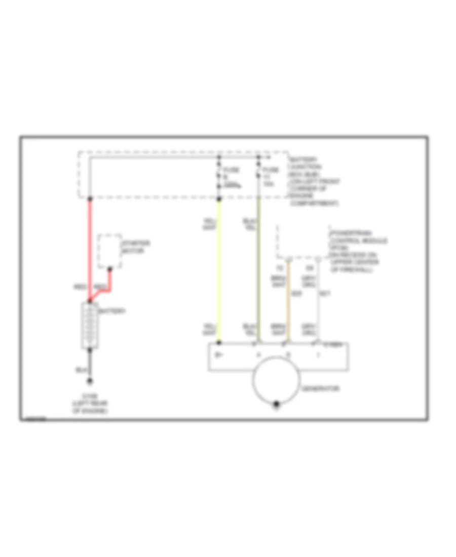 https://portal-diagnostov.com/license.html
Automotive Electricians Portal FZCO
Automotive Electricians Portal FZCO
https://portal-diagnostov.com/license.html
https://portal-diagnostov.com/license.html
Automotive Electricians Portal FZCO
Automotive Electricians Portal FZCOList of elements for 2.0L, Charging Wiring Diagram for Ford Escape 2003:
- Battery
- Battery junction box (bjb) (on left front corner of engine compartment)
- C102a
- Fuse 15a
- Fuse b 120a
- G108 (left rear of engine)
- Generator
- Powertrain control module (pcm) (in recess on upper center of firewall)
- Red
- Starter motor
3.0L
3.0L, Charging Wiring Diagram for Ford Escape 2003
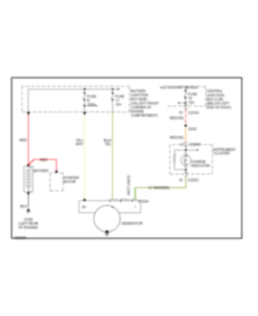 https://portal-diagnostov.com/license.html
Automotive Electricians Portal FZCO
Automotive Electricians Portal FZCO
https://portal-diagnostov.com/license.html
https://portal-diagnostov.com/license.html
Automotive Electricians Portal FZCO
Automotive Electricians Portal FZCOList of elements for 3.0L, Charging Wiring Diagram for Ford Escape 2003:
- (not used)
- Battery
- Battery junction box (bjb) (on left front corner of engine compartment)
- C102a
- C220c
- C270c
- Central junction box (cjb) (below left end of dash)
- Charge indicator
- Fuse 10a
- Fuse 15a
- Fuse b 120a
- G108 (left rear of engine)
- Generator
- Hot in start or run
- Instrument cluster
- Red
- S222
- Starter motor
SUPPLEMENTAL RESTRAINTS
Supplemental Restraints Wiring Diagram for Ford Escape 2003
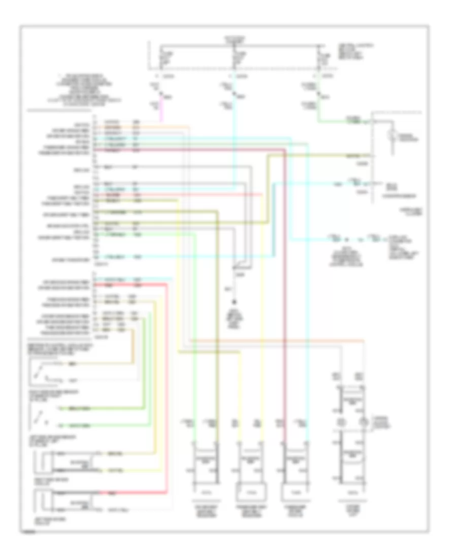 https://portal-diagnostov.com/license.html
Automotive Electricians Portal FZCO
Automotive Electricians Portal FZCO
https://portal-diagnostov.com/license.html
https://portal-diagnostov.com/license.html
Automotive Electricians Portal FZCO
Automotive Electricians Portal FZCOList of elements for Supplemental Restraints Wiring Diagram for Ford Escape 2003:
- Air bag indicator
- Air bag indicator ctrl
- Air bag sliding contact
- Air bag tone driver
- C2041a
- C2041b
- C220a
- C220b
- C270c
- C270d
- Central junction box (cjb) (below left end of dash)
- Data link connector (dlc) (partial) (on lower left side of dash)
- Driver air bag feed
- Driver air bag return
- Driver air bag unit
- Driver safety belt feed
- Driver safety belt return
- Driver seat seat belt tensioner
- Driver side air bag feed
- Driver side air bag return
- Driver side sensor feed
- Driver side sensor return
- Fuse f2.4 10a
- Fuse f2.5 5a
- Fuse f2.7 10a
- G203 (behind left side dash panel)
- Ground
- Hot in run or start
- Ignition
- Instrument cluster
- Iso bus
- Left side air bag module
- Left side air bag sensor (at base of left "b" pillar)
- Microprocessor
- Nca
- Pass safety belt feed
- Pass safety belt return
- Pass side air bag feed
- Pass side air bag return
- Pass side sensor feed
- Pass side sensor return
- Passenger air bag feed
- Passenger air bag module
- Passenger air bag return
- Passenger seat seat belt tensioner
- Pin shorting bar is engaged when module connector is disconnected from harness (shorting bar is connected between pins: 3-4, 6-7, 15-16, 18-22 & 20-21 conn. c2041a 2-3 & 5-6 conn. c2041b)
- Red
- Restraints control module (rcm) (beneath lower center of dash, on transmission tunnel)
- Right side air bag module
- Right side air bag sensor (at base of right "b" pillar)
- S205
- S208
- S215
- S219 (in main harn, near breakout to restraints control module)
- S225
- Shorting bar
- Solid state
TRANSMISSION
4WD Wiring Diagram for Ford Escape 2003
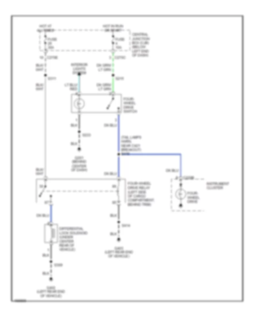 https://portal-diagnostov.com/license.html
Automotive Electricians Portal FZCO
Automotive Electricians Portal FZCO
https://portal-diagnostov.com/license.html
https://portal-diagnostov.com/license.html
Automotive Electricians Portal FZCO
Automotive Electricians Portal FZCOList of elements for 4WD Wiring Diagram for Ford Escape 2003:
- (tail lamps harn, near c421 breakout) s415
- C220b
- C270c
- C270e
- Central junction box (cjb) (below left end of dash)
- Differential lock solenoid (under center rear of vehicle)
- Four- wheel drive
- Four- wheel drive switch
- Four-wheel drive relay (left side of cargo compartment, behind trim)
- Fuse 10a
- Fuse 30a
- G201 (behind center of dash)
- G402 (left rear end of vehicle)
- G403 (left rear end of vehicle)
- Hot at all times
- Hot in run or start
- Instrument cluster
- Interior lights system
- S215
- S233
- S309
- S311
- S414
2.0L
2.0L, A/T Wiring Diagram for Ford Escape 2003
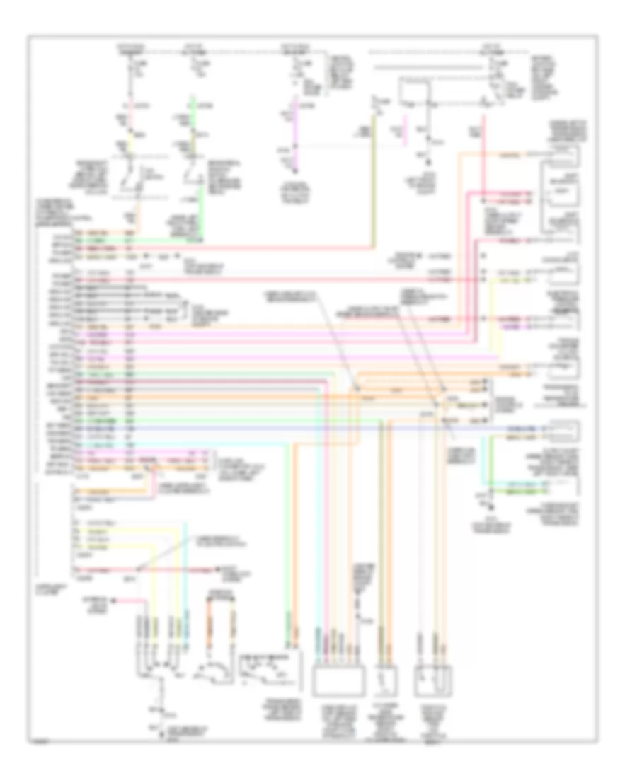 https://portal-diagnostov.com/license.html
Automotive Electricians Portal FZCO
Automotive Electricians Portal FZCO
https://portal-diagnostov.com/license.html
https://portal-diagnostov.com/license.html
Automotive Electricians Portal FZCO
Automotive Electricians Portal FZCOList of elements for 2.0L, A/T Wiring Diagram for Ford Escape 2003:
- (center rear of engine compt) g100
- (in recess on upper center of firewall) powertrain control module (pcm)
- (inside left of transmission) transmission hardware unit
- (near breakout to ignition switch)
- (near fuel injector 4 breakout)
- (near instrument cluster breakout)
- (near left
- (near mass air flow sensor breakout)
- (near oil pressure switch breakout)
- (near output shaft speed sensor beakout)
- (top center of transmission) g101
- 3-2t/ ccs solenoid
- 3-2t/ccs
- Battery junction box (bjb) (on left front corner of engine compt)
- Bpp sw
- Brake pedal position switch (on bracket, above brake pedal)
- Brake shift interlock (behind left side of dash, near steering column)
- C175
- C220a
- C220b
- C220c
- C251
- C270b
- C270c
- C270e
- Central junction box (cjb) (below left end of dash)
- Cooling fan relays, a/c clutch fan relay
- Cylinder head temperature sensor (right front of cylinder head)
- Data link connector (dlc) (on lower left side of dash)
- Ect sens
- Eeprom
- Electronic pressure control solenoid
- Engine controls system
- Epc sol
- Exterior lights system
- Front park/ turn lamp breakout) s139
- Fuse 10a
- Fuse 15a
- Fuse 30a
- Fuse 3a
- Fuse 5a
- G100 (center rear of engine compt)
- G101 (top center of transmission)
- G104 (left front of engine compt)
- Ground
- Hot at all times
- Hot in run or start
- Instrument cluster
- Maf
- Maf sens
- Mass airflow (maf) sensor (on left side of engine compt, in air intake duct)
- O/d sw
- O/d switch
- Oss sens
- Output shaft speed sensor (oss) (right rear of transmission, near left axle flange)
- Pcm power diode
- Pcm power relay
- Power
- Ref v
- Return
- S100
- S102
- S103 (near output shaft speed sensor breakout)
- S104
- S105
- S106
- S107
- S109
- S128
- S131
- S154
- S206
- S207
- S218
- S222
- S314
- Scp bus +
- Scp bus -
- Sens ret
- Shift interlock system
- Shift solenoid a
- Shift solenoid b
- Ss a
- Ss b
- Starting system
- Tan/red
- Tcc sol
- Tft sens
- Throttle position sensor (tps) (on throttle body)
- Torque converter clutch solenoid
- Tps
- Tr sens
- Transmission fluid temperature sensor
- Transmission range sensor (left side of transmission)
- Tss sens
- Turbine shaft speed sensor (tss) (right rear of transmission)
3.0L
3.0L, A/T Wiring Diagram for Ford Escape 2003
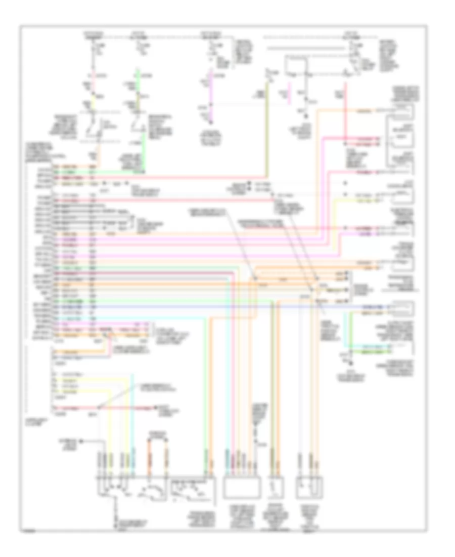 https://portal-diagnostov.com/license.html
Automotive Electricians Portal FZCO
Automotive Electricians Portal FZCO
https://portal-diagnostov.com/license.html
https://portal-diagnostov.com/license.html
Automotive Electricians Portal FZCO
Automotive Electricians Portal FZCOList of elements for 3.0L, A/T Wiring Diagram for Ford Escape 2003:
- (center rear of engine compt) g100
- (in recess on upper center of firewall) powertrain control module (pcm)
- (inside left of transmission) transmission hardware unit
- (near breakout to ignition switch)
- (near instrument cluster breakout)
- (near left
- (near mass air flow sensor breakout)
- (near throttle position sensor breakout)
- (top center of transmission) g101
- 3-2t/ ccs solenoid
- 3-2t/ccs
- Battery junction box (bjb) (on left front corner of engine compt)
- Bpp sw
- Brake pedal position switch (on bracket, above brake pedal)
- Brake shift interlock (behind left side of dash, near steering column)
- C175
- C220a
- C220b
- C220c
- C251
- C270b
- C270c
- C270e
- Central junction box (cjb) (below left end of dash)
- Cooling fan relays, a/c clutch fan relay
- Data link connector (dlc) (on lower left side of dash)
- Ect sens
- Eeprom
- Electronic pressure control solenoid
- Engine controls system
- Engine coolant temperature (ect) sensor (rear of right cylinder head)
- Epc sol
- Exterior lights system
- Front park/ turn lamp breakout) s139
- Fuse 10a
- Fuse 15a
- Fuse 30a
- Fuse 3a
- Fuse 5a
- G100 (center rear of engine compt)
- G101 (top center of transmission)
- G104 (left front of engine compt)
- Ground
- Hot at all times
- Hot in run or start
- Instrument cluster
- Maf
- Maf sens
- Mass airflow (maf) sensor (on left side of engine compt, in air intake duct)
- Near breakout for egr vacuum reg sol valve)
- O/d sw
- O/d switch
- Oss sens
- Output shaft speed sensor (oss) (right rear of transmission, near left axle flange)
- Pcm power diode
- Pcm power relay
- Power
- Ref v
- Return
- S100
- S102
- S103 (near heated oxygen sensor 11 breakout)
- S104
- S105
- S106
- S107
- S108 (near mass air flow sensor breakout)
- S109
- S128
- S131
- S154
- S206
- S207
- S218
- S222
- S314
- Scp bus +
- Scp bus -
- Sens ret
- Shift interlock system
- Shift solenoid a
- Shift solenoid b
- Ss a
- Ss b
- Starting system
- Tan/red
- Tcc sol
- Tft sens
- Throttle position sensor (tps) (on throttle body)
- Torque converter clutch solenoid
- Tps
- Tr sens
- Transmission fluid temperature sensor
- Transmission range sensor (left side of transmission)
- Tss sens
- Turbine shaft speed sensor (tss) (right rear of transmission)
WARNING SYSTEMS
Warning Systems Wiring Diagram for Ford Escape 2003
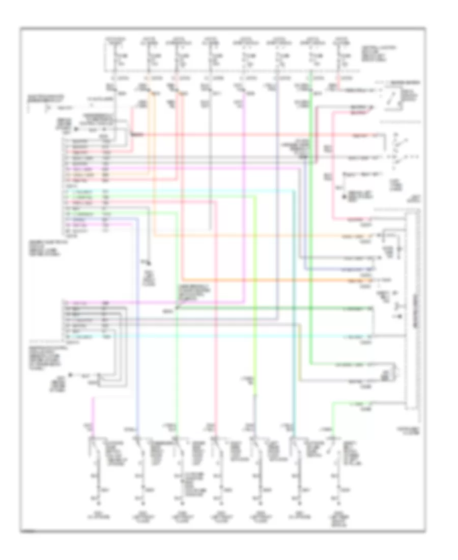 https://portal-diagnostov.com/license.html
Automotive Electricians Portal FZCO
Automotive Electricians Portal FZCO
https://portal-diagnostov.com/license.html
https://portal-diagnostov.com/license.html
Automotive Electricians Portal FZCO
Automotive Electricians Portal FZCOList of elements for Warning Systems Wiring Diagram for Ford Escape 2003:
- (behind center of dash)
- (behind left side of dash) g203
- (in main harness, near breakout to c211) s2001
- (near breakout to evap canister vent control solenoid)
- (near breakout to restraints control module)
- 0 off 1 park 2 head
- Air bag ind
- C201a
- C201b
- C2041a
- C220a
- C220b
- C220c
- C270c
- C270d
- C270e
- Central junction box (cjb) (below left end of dash)
- Door ajar ind
- Driver side front door lock unit
- Electrochromatic inside mirror unit
- Fuse 10a
- Fuse 30a
- Fuse 5a
- G201
- G201 (behind center of dash)
- G300 (left front floor)
- G301 (left front floor)
- G401 (in liftgate)
- G402 (left rear end of vehicle)
- Generic electronic module (behind lower center of dash)
- Hot at all times
- Hot in run or acc
- Hot in start or run
- Ignition switch
- Instrument cluster
- Key in ignition switch
- Left rear door lock actuator
- Liftgate ajar switch (on top center of liftgate)
- Liftgate glass ajar switch
- Light switch
- Microprocessor
- Passenger side front door lock unit
- Restraints control module (rcm) (beneath lower center of dash, on transmission tunnel)
- Right rear door lock actuator
- S2000
- S2002
- S205
- S208
- S212
- S215
- S216
- S220
- S222
- S302
- S309
- S311
- S401
- S600
- Safety belt ind
- Safety belt switch (at base of left "b" pillar)
- W/ autolamps
WIPER/WASHER
Front Wiper/Washer Wiring Diagram for Ford Escape 2003
 https://portal-diagnostov.com/license.html
Automotive Electricians Portal FZCO
Automotive Electricians Portal FZCO
https://portal-diagnostov.com/license.html
https://portal-diagnostov.com/license.html
Automotive Electricians Portal FZCO
Automotive Electricians Portal FZCOList of elements for Front Wiper/Washer Wiring Diagram for Ford Escape 2003:
- (below left
- C270b
- C270c
- Central junction box (cjb)
- End of dash)
- Fuse 10 20a
- G103 (right front of engine compartment)
- G104 (left front of engine compt)
- Hot in start or run
- Int
- Mist switch
- Off
- Park
- Run
- S114
- S131
- Tan/ red
- Washer switch
- Windshield washer pump motor (on right front of engine compt, below reservoir)
- Windshield wiper motor (on left rear of engine compt, beneath windshield)
- Wiper switch
- Wiper/ washer switch
Rear Wiper/Washer Wiring Diagram for Ford Escape 2003
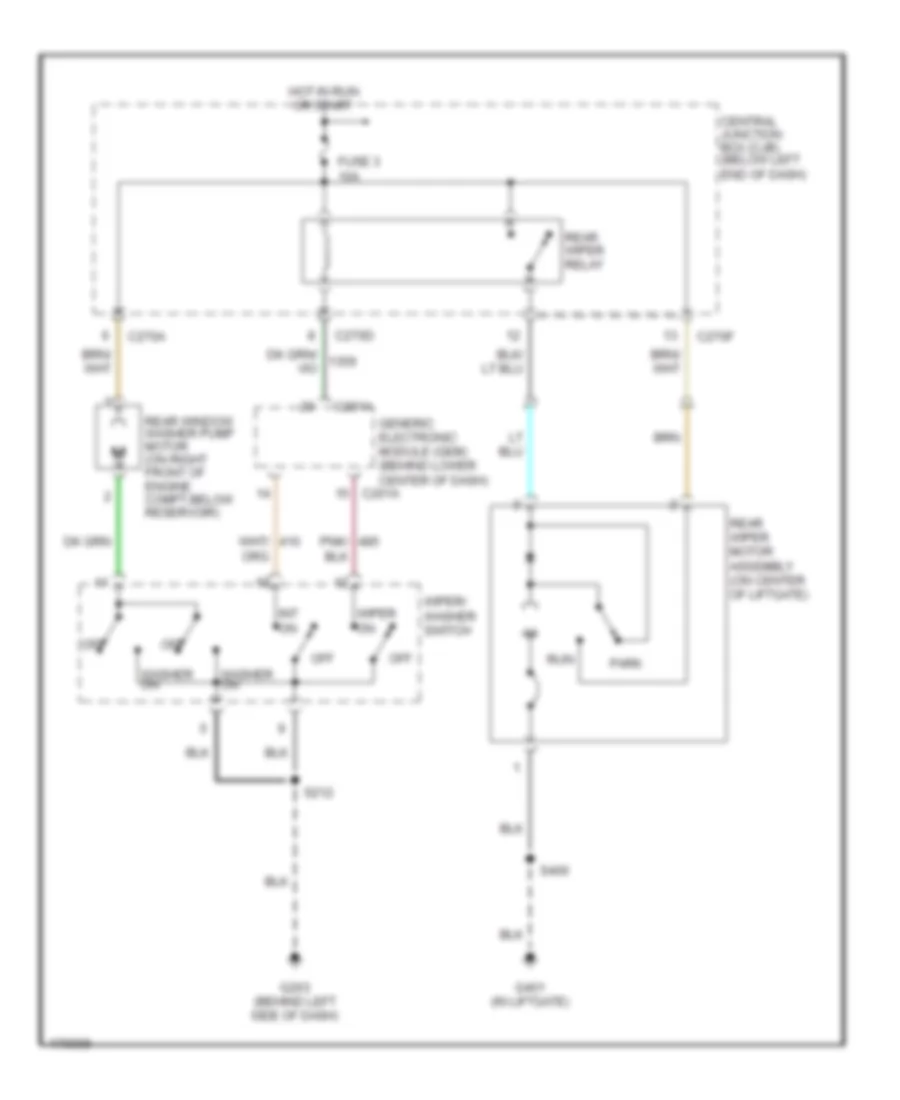 https://portal-diagnostov.com/license.html
Automotive Electricians Portal FZCO
Automotive Electricians Portal FZCO
https://portal-diagnostov.com/license.html
https://portal-diagnostov.com/license.html
Automotive Electricians Portal FZCO
Automotive Electricians Portal FZCOList of elements for Rear Wiper/Washer Wiring Diagram for Ford Escape 2003:
- C201a
- C270a
- C270d
- C270f
- Central junction box (cjb) (below left end of dash)
- Fuse 3 10a
- G203 (behind left side of dash)
- G401 (in liftgate)
- Generic electronic module (gem) (behind lower center of dash)
- Hot in run or start
- Int on
- Off
- Park
- Pnk/
- Rear window washer pump motor (on right front of engine compt,below reservoir)
- Rear wiper motor assembly (on center of liftgate)
- Rear wiper relay
- Run
- S212
- S400
- Washer on
- Wiper on
- Wiper/ washer switch

 Čeština
 Dansk
Dansk Deutsch
 Ελληνικά
 English
 English
 Español
 Suomi
Suomi Français
 Français
 Hrvatski
 Magyar
 Italiano
 日本語
日本語 한국어
한국어 Nederlands
 Polski
 Português
 Português
 Română
 Русский
 Slovenčina
 Slovenščina
 Svenska
 Türkçe
 中文 (中国)
