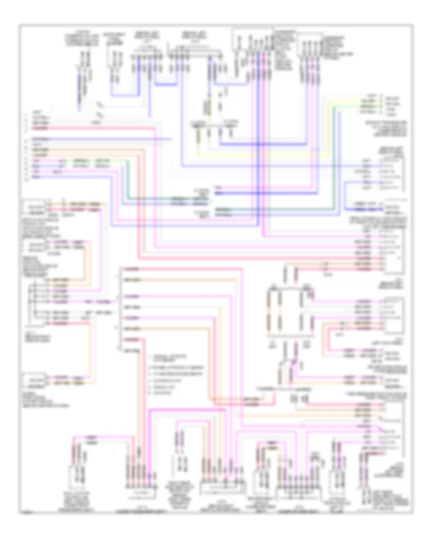
AIR CONDITIONING
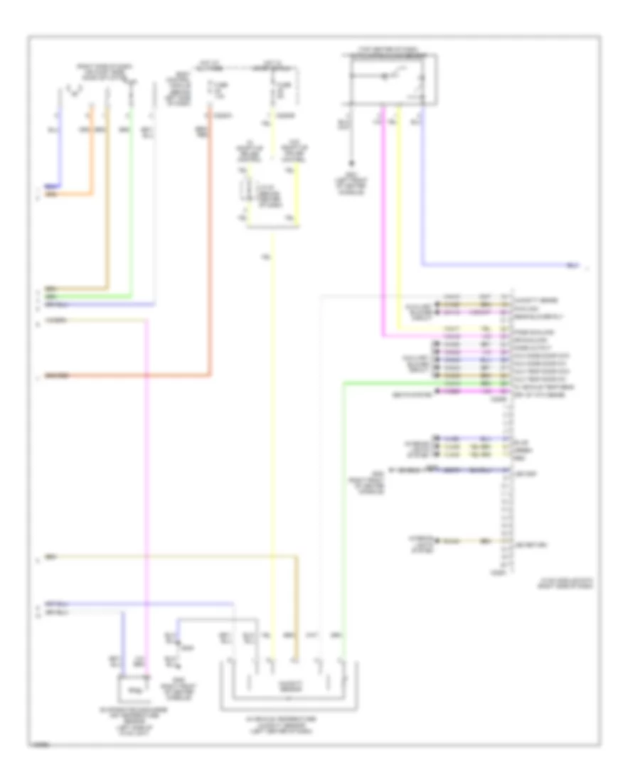
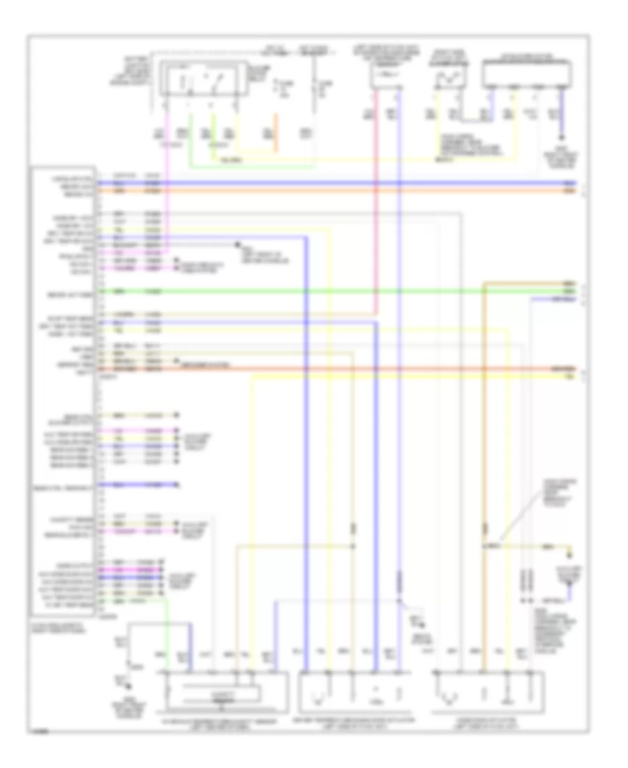
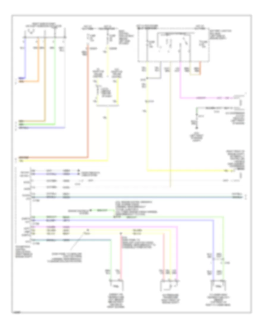
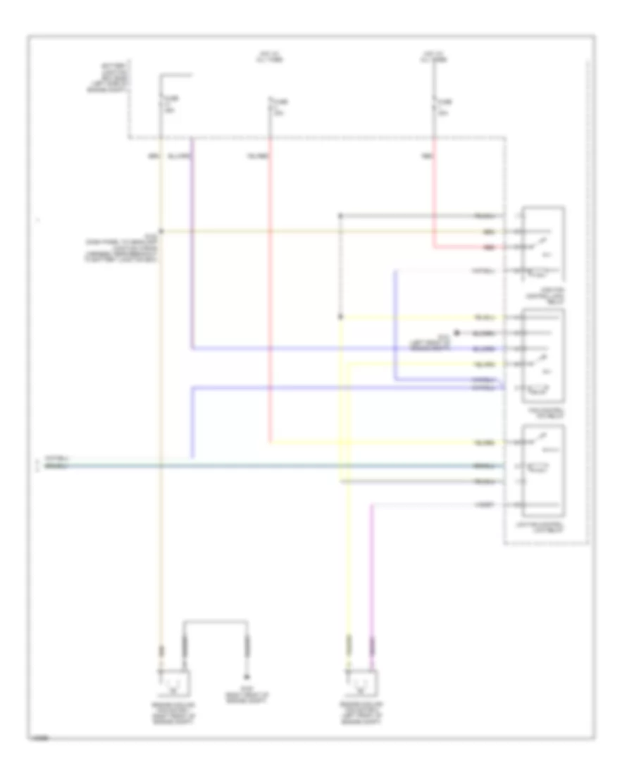
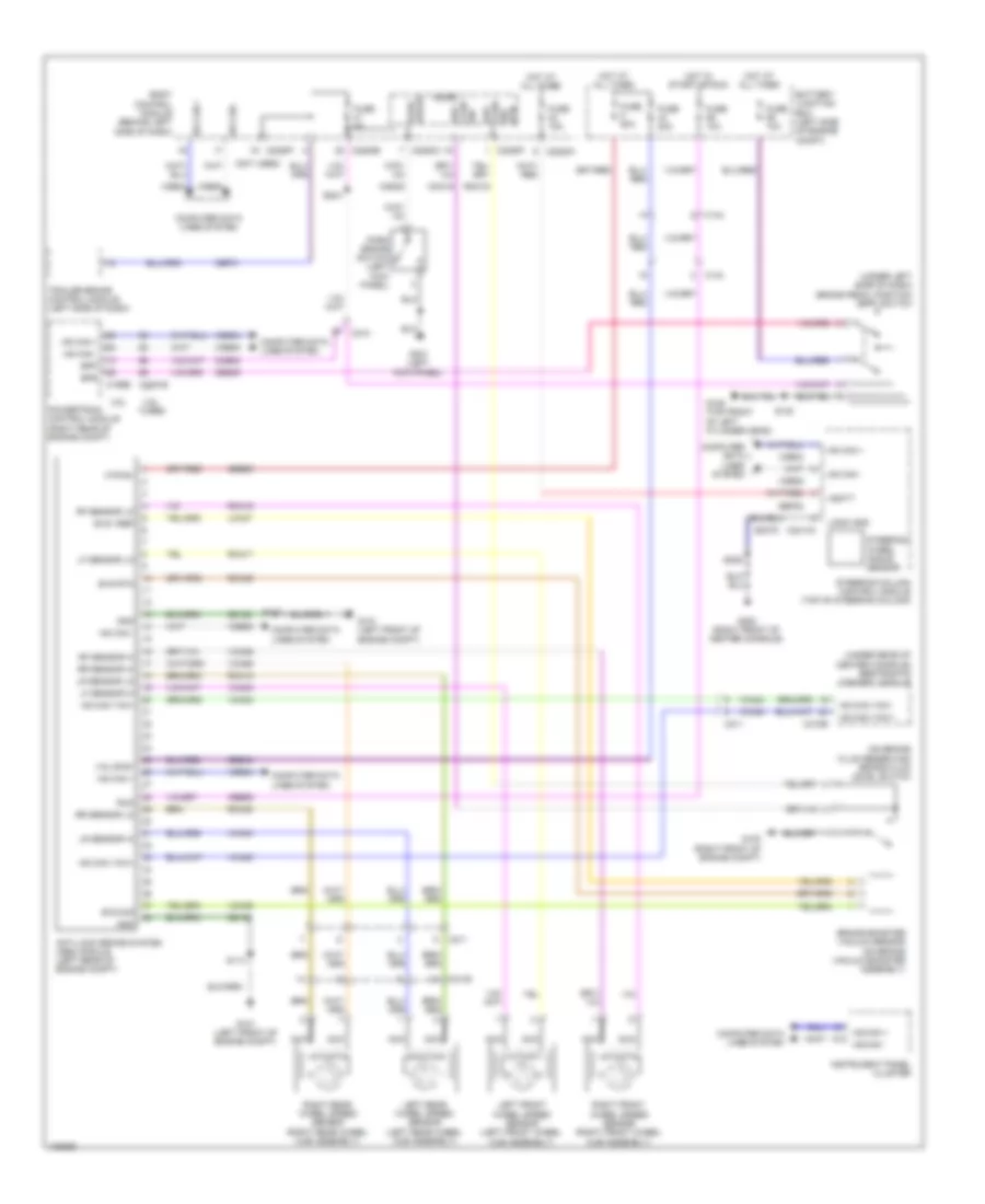
Automatic A/C Wiring Diagram (1 of 4) for Ford Flex SEL 2014
 https://portal-diagnostov.com/license.html
Automotive Electricians Portal FZCO
Automotive Electricians Portal FZCO
https://portal-diagnostov.com/license.html
https://portal-diagnostov.com/license.html
Automotive Electricians Portal FZCO
Automotive Electricians Portal FZCO
List of elements for Automatic A/C Wiring Diagram (1 of 4) for Ford Flex SEL 2014:
- (main wiring harness, near breakout to blower motor speed control) s210
- (main wiring harness, near breakout to c210)
- (on blower motor) blower motor speed control
- (right side of hvac unit) blower motor
- Aux mode dr fdbk
- Aux temp dr fdbk
- Auxiliary blower circuit
- Battery junction box (bjb) (left side of engine compt)
- Blower motor relay
- C210
- C213
- C228a
- C228b
- Ch123
- Ch207
- Ch208
- Ch212
- Ch213
- Ch228
- Ch229
- Ch238
- Ch239
- Cha35
- Cha36
- Cha37
- Chs11
- Chs12
- Computer data lines system
- Crd02
- Defogger system
- Defrost req
- Driv temp act fdbk
- Driv temp dr ccw
- Driv temp dr cw
- Driver temperature blend door actuator (left side of hvac unit)
- Drv heater feed
- Drv htd seat element
- Evap temp sens
- Fr blwr rly
- Fuse 20a (or 30a)
- Fuse 40a
- Fuse 5a
- G200 (right front of center console)
- G201 (left front of center console)
- Gd374
- Gnd
- Hot at all times
- Hot in start or run
- Hvac module datc (right side of dash)
- Lh111
- Mode 1 act fdbk
- Mode door actuator (left side of hvac unit)
- Mode dr 1 ccw
- Mode dr 1 cw
- Mot+
- Mot-
- Ms can +
- Ms can -
- Pass heater feed
- Pass htd seat element
- Pass st ntc sense
- Pass temp act fdbk rear ctrl blower output
- Pass temp door ccw
- Pass temp door cw
- Passenger temperature blend door actuator (right side of dash)
- Pwm
- Rear ctrl sig feed1
- Rear ctrl sig feed2
- Rear ctrl sig feed3
- Rear temp input
- Recirc act fdbk
- Recirc ccw
- Recirc cw
- Return
- Rh111
- S200
- S208
- S209 (main wiring harness, near breakout to accessory protocol interface module)
- Sbb29
- Sbp46
- Seats system
- Var blwr ctrl
- Vbatt
- Vdb06
- Vdb07
- Vh101
- Vh406
- Vh436
- Vh438
- Vh440
- Vh441
- Vha09
- Vha18
- Vha19
- Vha39
- Vhs27
- Vref
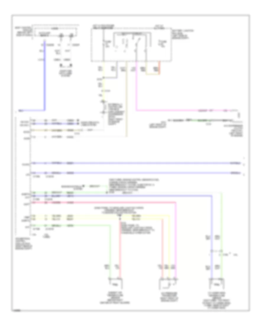
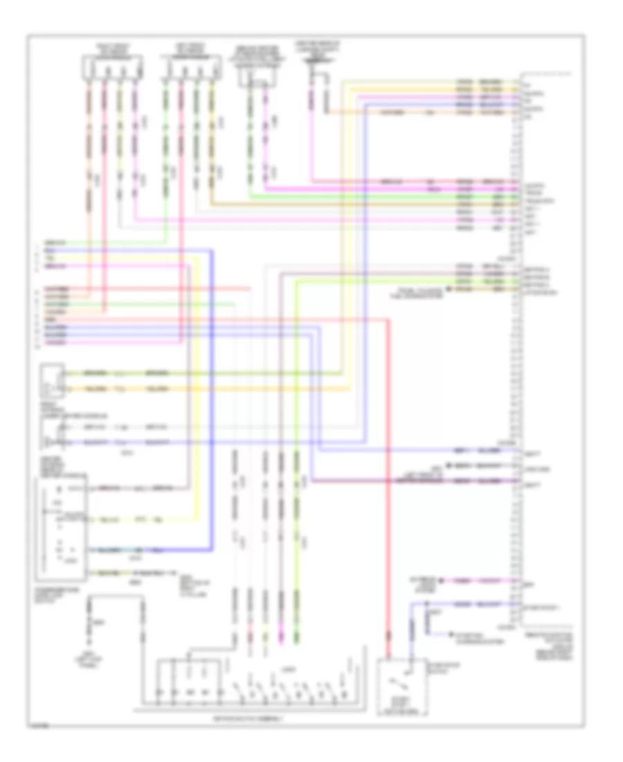
Automatic A/C Wiring Diagram (2 of 4) for Ford Flex SEL 2014
 https://portal-diagnostov.com/license.html
Automotive Electricians Portal FZCO
Automotive Electricians Portal FZCO
https://portal-diagnostov.com/license.html
https://portal-diagnostov.com/license.html
Automotive Electricians Portal FZCO
Automotive Electricians Portal FZCOList of elements for Automatic A/C Wiring Diagram (2 of 4) for Ford Flex SEL 2014:
- (right side of dash) air inlet mode door actuator
- (top center of dash) autolamp/sunload sensor
- Aux mode door ccw
- Aux mode door cw
- Aux temp door ccw
- Aux temp door cw
- Auxiliary blower circuit
- Body control module (behind left side of dash)
- C2280a
- C2280b
- C228b
- C228c
- Ch112
- Ch242
- Ch243
- Ch244
- Ch245
- Dr sunload
- Drv st ntc sense
- Evaporator discharge air temperature sensor (left side of hvac unit)
- Fuse 10a
- Fuse 5a
- G200 (right front of center console)
- G201 (left front of center console)
- Gd375
- Green
- Hot at all times
- Hot in start or run
- Humidity sense
- Humidity sensor
- Hvac module datc (right side of dash)
- In vehicle temp sens
- In-vehicle temperature/ humidity sensor (left center of dash)
- Interior lights system
- J/c 24 (behind center of dash)
- Led gnd
- Led return
- Mode output
- Pass sunload
- Pwm com
- Rear blower rly
- Red
- Rln44
- S205
- Seats system
- Vh413
- Vh414
- Vh416
- Vh417
- Vha25
- Vha38
- Vhs26
- Vln48
- Vln49
- Vln50
- W/ adaptive cruise control
- W/o adaptive cruise control
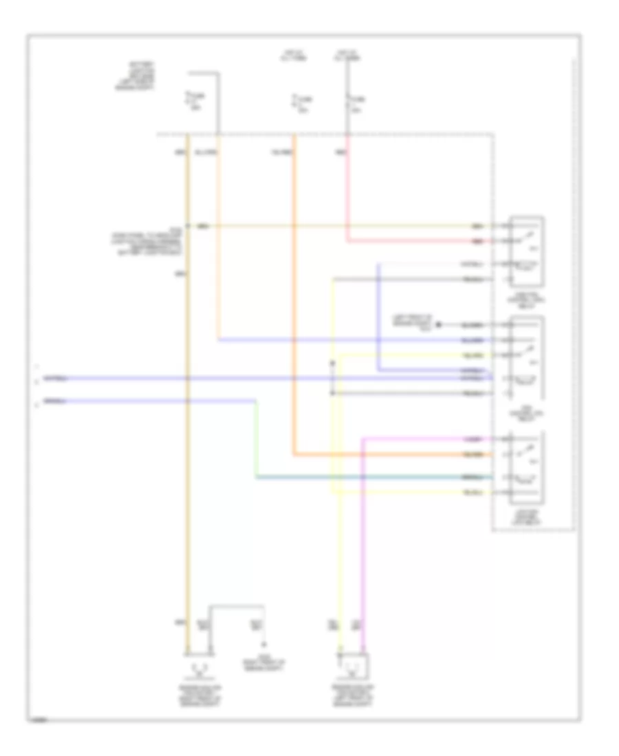
Automatic A/C Wiring Diagram (3 of 4) for Ford Flex SEL 2014
 https://portal-diagnostov.com/license.html
Automotive Electricians Portal FZCO
Automotive Electricians Portal FZCO
https://portal-diagnostov.com/license.html
https://portal-diagnostov.com/license.html
Automotive Electricians Portal FZCO
Automotive Electricians Portal FZCOList of elements for Automatic A/C Wiring Diagram (3 of 4) for Ford Flex SEL 2014:
- (dash panel to headlamp junction wiring harness, near breakout to engine cooling fan motor) s101
- (non-turbo: engine control sensor & fuel charge wiring harness, near breakout to fuel injector no. 3) (turbo: engine wiring harness, near breakout to c1045) s126
- 3.5l
- 3.5l turbo
- A/c clutch relay
- A/c compressor clutch field coil (left front of engine)
- A/c pressure transducer (right front of engine compt)
- Aat
- Accr
- Acpt
- Ambient air temperature sensor (behind right center of front bumper)
- Autolamp sens in
- Battery junction box (bjb) (left side of engine compt)
- Body control module (behind left side of dash)
- C1381b
- C1381e
- C144
- C175b
- C175e
- C192
- C2280b
- C2280f
- Cec01
- Cec02
- Ch302
- Cht
- Computer data lines system
- Cylinder head temperature sensor (non-turbo: top front of right cylinder head) (turbo: rear of right cylinder head)
- Engine controls
- Evdc
- Externally controlled variable displacement compressor (evdc) (right front of engine compt)
- Fc/hfc
- Fuse 10a
- Fuse 15a
- G101 (left front of engine compt)
- Hot at all times
- Hot w/ pcm power relay energized
- Hs can +
- Hs can -
- Hs can+
- Hs can-
- Le424
- Lfc
- Micro
- Powertrain control module (pcm) (right rear of engine compt)
- Re405
- Re407
- S108
- S114
- S133 (dash panel to headlamp junction wiring harness, near breakout to windshield wiper motor)
- Sigrtn
- System
- Vdb04
- Vdb05
- Ve462
- Ve712
- Ve750
- Vh433
- Vlf14
- Vref
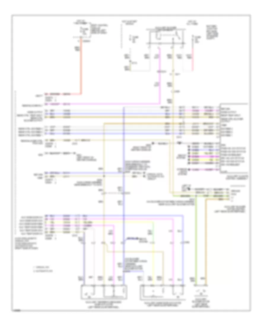
Automatic A/C Wiring Diagram (4 of 4) for Ford Flex SEL 2014
 https://portal-diagnostov.com/license.html
Automotive Electricians Portal FZCO
Automotive Electricians Portal FZCO
https://portal-diagnostov.com/license.html
https://portal-diagnostov.com/license.html
Automotive Electricians Portal FZCO
Automotive Electricians Portal FZCOList of elements for Automatic A/C Wiring Diagram (4 of 4) for Ford Flex SEL 2014:
- (left front of engine compt) g101
- Battery junction box (bjb) (left side of engine compt)
- Engine cooling fan motor 1 (right front of engine compt)
- Engine cooling fan motor 2 (left front of engine compt)
- Fan control (fc) relay
- Fuse 25a
- Fuse 40a
- G100 (right front of engine compt)
- High fan control (hfc) relay
- Hot at all times
- Low fan control (lfc) relay
- Red
- S122 (dash panel to headlamp junction wiring harness, near breakout to battery junction box)
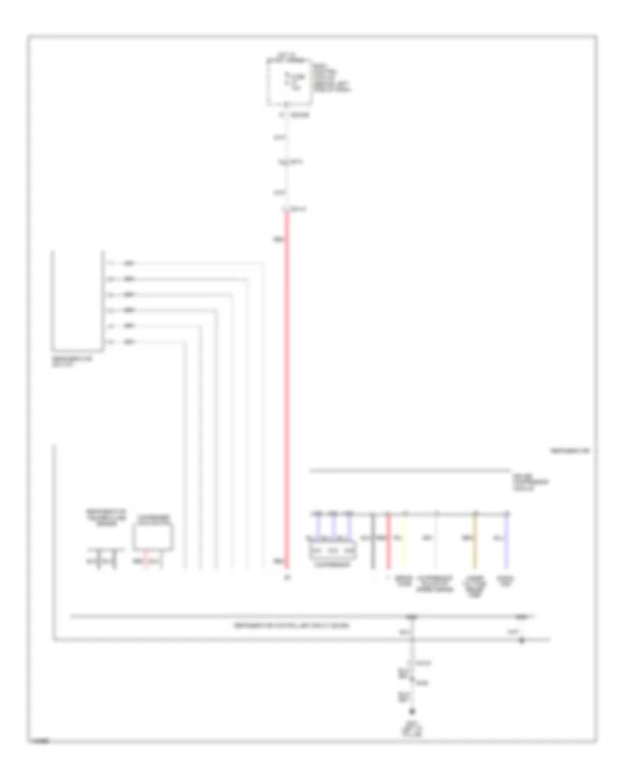
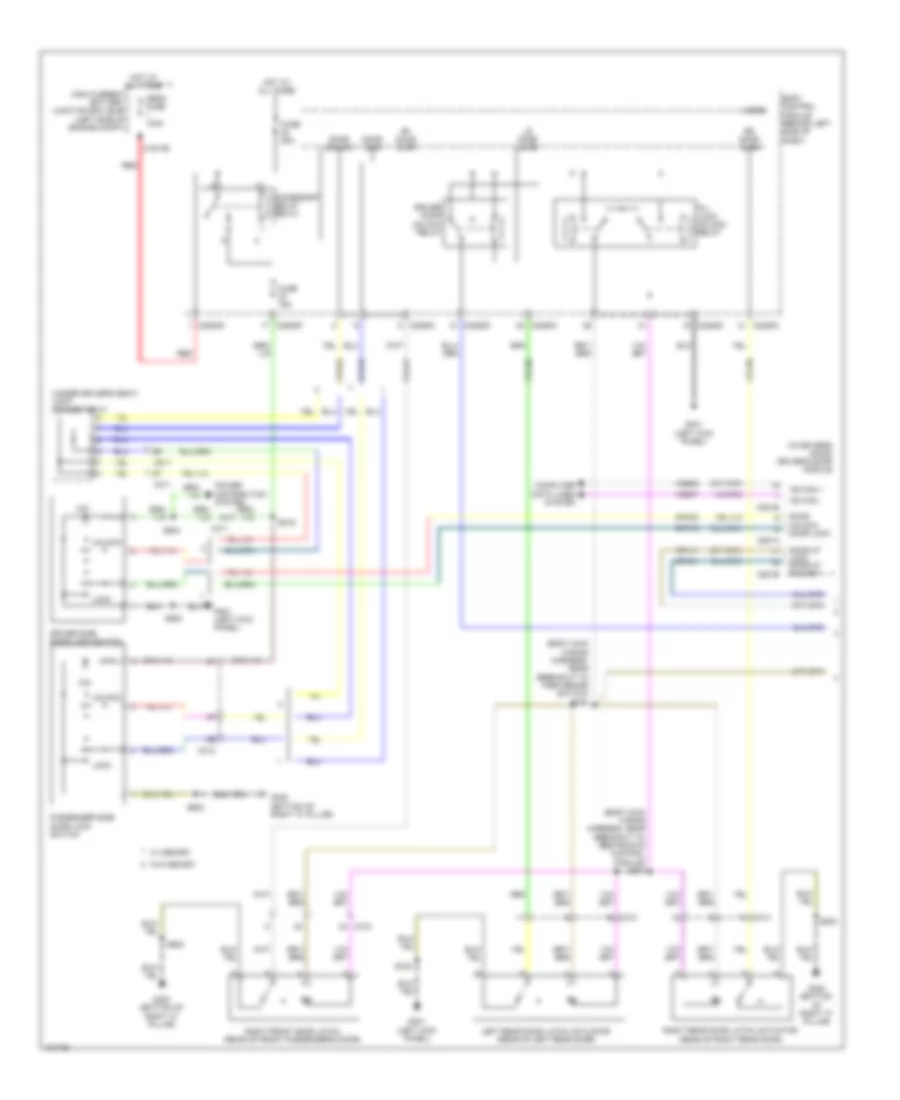
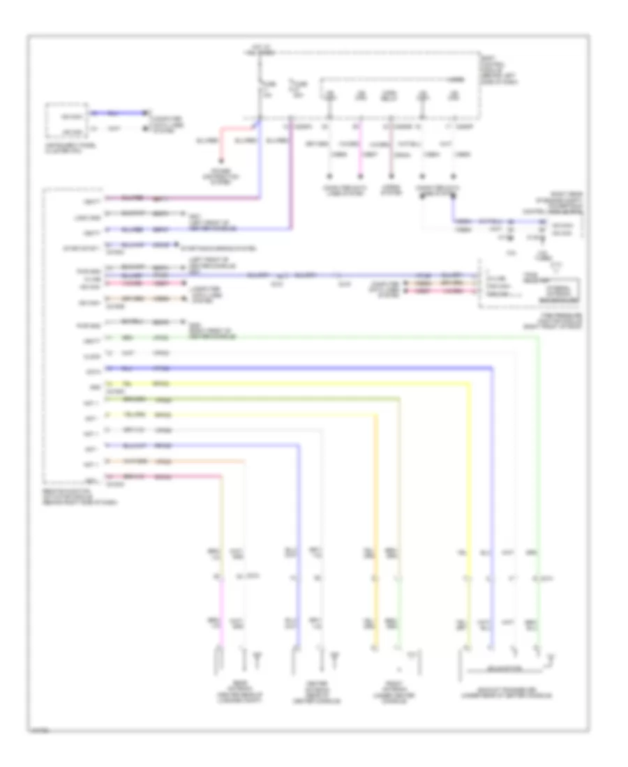
Auxiliary Blower Wiring Diagram for Ford Flex SEL 2014
 https://portal-diagnostov.com/license.html
Automotive Electricians Portal FZCO
Automotive Electricians Portal FZCO
https://portal-diagnostov.com/license.html
https://portal-diagnostov.com/license.html
Automotive Electricians Portal FZCO
Automotive Electricians Portal FZCOList of elements for Auxiliary Blower Wiring Diagram for Ford Flex SEL 2014:
- (+)
- (-)
- (left "d" pillar) g401
- (main wiring harness, near breakout to accessory protocol interface module) s209
- Automatic a/c
- Aux mode door ccw
- Aux mode door cw
- Aux mode door fdbk
- Aux temp door ccw
- Aux temp door cw
- Aux temp door fdbk
- Auxiliary blower motor (left rear quarterpanel)
- Auxiliary blower motor control (left rear quarterpanel)
- Auxiliary blower motor relay
- Auxiliary climate control assembly
- Auxiliary mode door actuator (left rear quarterpanel)
- Auxiliary temperature blend door actuator (left rear quarterpanel)
- Battery junction box (bjb) (left side of engine compt)
- Body control module (behind left side of dash)
- C210
- C211
- C214
- C215
- C2280a
- C228a
- C228b
- C2357a
- C2357b
- C465
- Ch112
- Ch242
- Ch243
- Ch244
- Ch245
- Cha35
- Cha36
- Cha37
- Chs47
- Chs48
- Chs49
- Chs51
- Chs52
- Chs53
- Drv hs high status
- Drv hs low status
- Drv hs request
- Fuse 10a
- Fuse 30a
- Fuse 5a
- G200 (right front of center console)
- G201 (left front of center console)
- Gd374
- Gd375
- Gnd
- Ground
- Hot at all times
- Hot in start or run
- Hvac module emtc (manual a/c) hvac module datc (automatic a/c) (right side of dash)
- Illum
- Interior lights system
- Lh111
- Manual a/c
- Manual a/c & automatic a/c circuit
- Mode output
- Near auxiliary blower motor) s410
- Pass hs high status
- Pass hs low status
- Pass hs request
- Pwm
- Rear blower ctrl pwm com c2357b
- Rear blower rly
- Rear ctrl blower output
- Rear ctrl sig feed 1
- Rear ctrl sig feed 2
- Rear ctrl sig feed 3
- Rear ctrl temp input rear ctrl blower output
- Rear temp input
- Return
- Rh111
- S112
- S208 (main wiring harness, near breakout to c210)
- S341
- S412 (a/c blower motor feed wiring harness, near auxiliary blower motor)
- Sbp46
- Seats system
- Sig feed 1
- Sig feed 2
- Sig feed 3
- Vbatt
- Vha09
- Vha18
- Vha19
- Vha25
- Vha38
- Vha39
- Vln04
- Vref
Cool Box Wiring Diagram for Ford Flex SEL 2014
 https://portal-diagnostov.com/license.html
Automotive Electricians Portal FZCO
Automotive Electricians Portal FZCO
https://portal-diagnostov.com/license.html
https://portal-diagnostov.com/license.html
Automotive Electricians Portal FZCO
Automotive Electricians Portal FZCOList of elements for Cool Box Wiring Diagram for Ford Flex SEL 2014:
- Body control module (behind left side of dash)
- C215
- C2280b
- C3415
- Ch1
- Ch2
- Ch3
- Compressor
- Compressor run/stop speed sense
- Condenser cooling fan
- Driver compressor module
- Error code
- Fuse 10a
- G401 (left "d" pillar)
- Gnd
- Hot in start or run
- Red
- Refrigerator
- Refrigerator controller circuit board
- Refrigerator switch
- Refrigerator temperature sensor
- S420
- Signal gnd
- Under voltage sense vref
Manual A/C Wiring Diagram (1 of 3) for Ford Flex SEL 2014
 https://portal-diagnostov.com/license.html
Automotive Electricians Portal FZCO
Automotive Electricians Portal FZCO
https://portal-diagnostov.com/license.html
https://portal-diagnostov.com/license.html
Automotive Electricians Portal FZCO
Automotive Electricians Portal FZCOList of elements for Manual A/C Wiring Diagram (1 of 3) for Ford Flex SEL 2014:
- (left side of hvac unit) evaporator discharge air temperature sensor
- (main wiring harness, near breakout to blower motor speed control) s210
- (main wiring harness, near breakout to c210)
- (on blower motor) blower motor speed control
- (right side of hvac unit) blower motor
- Aux mode door ccw
- Aux mode door cw
- Aux mode dr fdbk
- Aux temp door ccw
- Aux temp door cw
- Aux temp dr fdbk
- Auxiliary blower circuit
- Battery junction box (bjb) (left side of engine compt)
- Blower motor relay
- C210
- C2357a
- C2357b
- Ch112
- Ch123
- Ch207
- Ch208
- Ch228
- Ch229
- Ch238
- Ch239
- Ch242
- Ch243
- Ch244
- Ch245
- Cha35
- Cha36
- Cha37
- Computer data lines system
- Crd02
- Defogger system
- Defrost req
- Driv temp act fdbk
- Driv temp dr ccw
- Driv temp dr cw
- Driver temperature blend door actuator (left side of hvac unit)
- Evap temp sens
- Fr blwr rly
- Fuse 40a
- Fuse 5a
- G200 (right front of center console)
- G201 (left front of center console)
- Gd374
- Gnd
- Hot at all times
- Hot in run or start
- Humidity sense
- Humidity sensor
- Hvac module emtc (right side of dash)
- In veh temp sens
- In-vehicle temperature/humidity sensor (left center of dash)
- Lh111
- Mode 1 act fdbk
- Mode door actuator (left side of hvac unit)
- Mode dr 1 ccw
- Mode dr 1 cw
- Mode output
- Mot+
- Mot-
- Ms can +
- Ms can -
- Pwm
- Pwm com
- Rear blower rly
- Rear ctrl blower output
- Rear ctrl tempinput
- Rear sig feed 1
- Rear sig feed 2
- Rear sig feed 3
- Recirc act fdbk
- Recirc ccw
- Recirc cw
- Return
- Rh111
- S205
- S208
- S209 (main wiring harness, near breakout to accessory protocol interface module)
- Sbp46
- Seats system
- Var blwr ctrl
- Vbatt
- Vdb06
- Vdb07
- Vh101
- Vh406
- Vh413
- Vh414
- Vh436
- Vh438
- Vh440
- Vha09
- Vha18
- Vha19
- Vha25
- Vha38
- Vha39
- Vref
Manual A/C Wiring Diagram (2 of 3) for Ford Flex SEL 2014
 https://portal-diagnostov.com/license.html
Automotive Electricians Portal FZCO
Automotive Electricians Portal FZCO
https://portal-diagnostov.com/license.html
https://portal-diagnostov.com/license.html
Automotive Electricians Portal FZCO
Automotive Electricians Portal FZCOList of elements for Manual A/C Wiring Diagram (2 of 3) for Ford Flex SEL 2014:
- (3.5l: engine control sensor & fuel charge wiring harness, near breakout to fuel injector 3) (3.5l turbo: engine wiring harness, near breakout to c1045) s126
- (dash panel to headlamp junction wiring harness, near breakout to engine cooling fan motor)
- (right front of engine compt) externally controlled variable displacement compressor (evdc)
- (right side of dash) air inlet mode door actuator
- A/c clutch relay
- A/c compressor clutch field coil (left front of engine)
- A/c pressure transducer (right front of engine compt)
- Aat
- Accr
- Acpt
- Ambient air temperature (aat) sensor (behind right center of front bumper)
- Battery junction box (bjb) (left side of engine compt)
- Body control module (bcm) (behind left side of dash)
- C144
- C175b
- C175e
- C192
- C2280a
- C2280b
- Cec01
- Cec02
- Ch302
- Cht
- Compt)
- Computer data lines system
- Cylinder head temperature (cht) sensor (top front of right cylinder head)
- Engine controls system
- Evdc
- Fc/hfc
- Fuse 10a
- Fuse 15a
- Fuse 5a
- G101 (left front of engine
- Hot at all times
- Hot in run or start
- Hot w/ pcm power relay energized
- Hs can +
- Hs can -
- J/c 24 (behind center of dash)
- Le424
- Lfc
- Powertrain control module (pcm) (right rear of engine compt)
- Re405
- Re407
- S101
- S108
- S114
- S133 (dash panel to headlamp junction wiring harness, near breakout to windshield wiper motor)
- Sigrtn
- Vdb04
- Vdb05
- Ve462
- Ve712
- Ve750
- Vh433
- Vref
- W/ adaptive cruise control
- W/o adaptive cruise control
Manual A/C Wiring Diagram (3 of 3) for Ford Flex SEL 2014
 https://portal-diagnostov.com/license.html
Automotive Electricians Portal FZCO
Automotive Electricians Portal FZCO
https://portal-diagnostov.com/license.html
https://portal-diagnostov.com/license.html
Automotive Electricians Portal FZCO
Automotive Electricians Portal FZCOList of elements for Manual A/C Wiring Diagram (3 of 3) for Ford Flex SEL 2014:
- Battery junction box (bjb) (left side of engine compt)
- Engine cooling fan motor 1 (right front of engine compt)
- Engine cooling fan motor 2 (left front of engine compt)
- Fan control (fc) relay
- Fuse 25a
- Fuse 40a
- G100 (right front of engine compt)
- G101 (left front of engine compt)
- High fan control (hfc) relay
- Hot at all times
- Low fan control (lfc) relay
- Red
- S122 (dash panel to headlamp junction wiring harness, near breakout to battery junction box)
ANTI-LOCK BRAKES
Anti-lock Brakes Wiring Diagram for Ford Flex SEL 2014
 https://portal-diagnostov.com/license.html
Automotive Electricians Portal FZCO
Automotive Electricians Portal FZCO
https://portal-diagnostov.com/license.html
https://portal-diagnostov.com/license.html
Automotive Electricians Portal FZCO
Automotive Electricians Portal FZCOList of elements for Anti-lock Brakes Wiring Diagram for Ford Flex SEL 2014:
- (not used)
- (on brake fluid reservoir) brake fluid level switch
- (under left side of dash) brake pedal position (bpp) switch
- (under rear of center console) restraints control module
- 3.5l
- 3.5l turbo
- Anti-lock brake system (abs) module (left rear of engine compt)
- Battery junction box (left side of engine compt)
- Body control module (behind left side of dash)
- Bpp
- Bps
- Brake booster vacuum sensor (on brake vacuum booster assembly)
- Brk fluid sw
- Brk fluid sw rtn
- Bvs rtn
- Bvs sig
- Bvs vref
- C1381b
- C144
- C175b
- C210
- C211
- C2280a
- C2280b
- C2280c
- C2280f
- C2414a
- C310b
- C3138
- Cbb89
- Cbp31
- Ccb08
- Ces09
- Cmc19
- Cmc25
- Computer data lines system
- Fuse 10a
- Fuse 15a
- Fuse 20a
- Fuse 50a
- Fuse 5a
- G100 (right front of engine compt)
- G101 (left front of engine compt)
- G106 (top front of left cylinder head)
- G200 (right front of center console)
- G301 (left kick panel)
- Gd120
- Gd375
- Gnd
- Hot at all times
- Hot in start or run
- Hs can +
- Hs can -
- Hs can yaw+
- Hs can yaw-
- Instrument panel cluster
- Lca37
- Left front wheel speed sensor (left front wheel hub assembly)
- Left rear wheel speed sensor (left rear wheel hub assembly)
- Lf sensor hi
- Lf sensor lo
- Logic gnd
- Lr sensor hi
- Lr sensor lo
- Micro
- Mtr b+
- Nca
- Park brake
- Park brake switch (left kick panel)
- Powertrain control module (right rear of engine compt)
- Rca17
- Rca18
- Rca19
- Rca20
- Rca36
- Rf sensor hi
- Rf sensor lo
- Right front wheel speed sensor (right front wheel hub assembly)
- Right rear wheel speed sensor (right rear wheel hub assembly)
- Rmc19
- Rr sensor hi
- Rr sensor lo
- Run
- S114
- S117
- S130
- S204
- S206
- Sbb05
- Sbb43
- Sbp23
- Steering column control module (top of steering column)
- Steering wheel angle sensor
- Trailer brake control module (left side of dash)
- Valve b+
- Vbatt
- Vca03
- Vca04
- Vca05
- Vca06
- Vca23
- Vca24
- Vca36
- Vdb04
- Vdb05
ANTI-THEFT
Forced Entry Wiring Diagram, with Intelligent Access (1 of 2) for Ford Flex SEL 2014
 https://portal-diagnostov.com/license.html
Automotive Electricians Portal FZCO
Automotive Electricians Portal FZCO
https://portal-diagnostov.com/license.html
https://portal-diagnostov.com/license.html
Automotive Electricians Portal FZCO
Automotive Electricians Portal FZCOList of elements for Forced Entry Wiring Diagram, with Intelligent Access (1 of 2) for Ford Flex SEL 2014:
- (bottom of right "c" pillar)
- (bottom of right "c" pillar) g300
- (left front of engine compt) g101
- (left kick panel) g301
- (right front of center console) g200
- (x2)
- Accessory delay relay
- Ajar
- All lock
- Backup transceiver (under rear of center console)
- Body control module (behind left side of dash)
- C1617b
- C214
- C215
- C2153d
- C2153e
- C219
- C2280a
- C2280b
- C2280c
- C2280d
- C2280f
- C2280g
- C311
- C312
- C313
- C314
- Clk
- Computer data lines system
- Cpk19
- Cpk23
- Cpk28
- Cpl11
- Cpl25
- Cpl26
- Cpl31
- Cpl36
- Cpl39
- Cpl51
- Cpl52
- Crh04
- Data
- Door lock
- Door unlock
- Dr door unlock
- Driver side door lock switch
- Fuse 10a
- Fuse 15a
- Fuse 20a
- Fuse 5a
- Fuse 7.5a
- G201 (left front of center console)
- G300
- G301 (left kick panel)
- Gd374
- Gd375
- Gnd
- High current battery junction box (bjb) (left side of engine compt)
- Hood ajar
- Hood switch (left front corner of engine compt)
- Horn rly
- Horns system
- Hot at all times
- Internal antenna
- Joint connector (under driver's seat)
- Joint connector 23 (under driver's seat)
- K line
- Keypad illm
- Left front door latch (rear of driver's door)
- Left rear door latch actuator (rear of left rear door)
- Lf door ajar
- Lock
- Lpk32
- Lr door ajar
- Mega fuse 100a
- Micro
- Ms can +
- Ms can -
- Ms can+
- Ms can-
- Pats gnd
- Pats vcc
- Power distribution system
- Pwr gnd
- Red
- Remote function actuator module (behind right side of dash)
- Rf door ajar
- Right front door latch (rear of front passenger's door)
- Right rear door latch actuator (rear of right rear door)
- Rke receiver
- Rpk32
- Rpk39
- Rr door ajar
- S143
- S216
- S307 (body main wiring harness, near breakout to restraints control module)
- S308 (body main wiring harness, near breakout to park brake switch)
- S500
- S502
- S503
- S600
- S800
- Solid state
- Tire pressure monitor module (right front of roof)
- Tpms receiver
- Unlock
- Vbatt
- Vdb06
- Vdb07
- Vpk32
- Vpk33
- Vpk39
- Vpk40
- Vpl56
Forced Entry Wiring Diagram, with Intelligent Access (2 of 2) for Ford Flex SEL 2014
 https://portal-diagnostov.com/license.html
Automotive Electricians Portal FZCO
Automotive Electricians Portal FZCO
https://portal-diagnostov.com/license.html
https://portal-diagnostov.com/license.html
Automotive Electricians Portal FZCO
Automotive Electricians Portal FZCOList of elements for Forced Entry Wiring Diagram, with Intelligent Access (2 of 2) for Ford Flex SEL 2014:
- (behind center of rear bumper) liftgate intelligent access antenna
- (center rear of luggage compt) rear antenna
- (x2)
- 1/2
- 3/4
- 5/6
- 7/8
- 9/0
- Ant +
- Ant -
- Bpp
- C212
- C214
- C215
- C2153a
- C2153b
- C2153c
- C311
- C312
- C405
- Ccb08
- Cdc35
- Center antenna (rear of center console)
- Cpk29
- Cpk30
- Cpk31
- Cpl45
- Exterior lights system
- Front antenna (under center console)
- G201 (left front of center console)
- G300 (bottom of right "c" pillar)
- G301 (left kick panel)
- Gd374
- Gnd
- Ia1
- Ia2
- Ia2 rtn
- Ia3
- Ia3 rtn
- Ian rtn
- Keypad a
- Keypad b
- Keypad c
- Keypad switch assembly
- Left front exterior door handle
- Liftgate sw
- Lock
- Logic
- Logic gnd
- Passenger side door lock switch
- Red
- Remote function actuator module (behind right side of dash)
- Right front exterior door handle
- Rpk01
- Rpk02
- Rpk05
- Rpk06
- Rpk07
- Rpk08
- S207
- S500
- S600
- Sbp11
- Sbp27
- Start/ stop 1 (active high)
- Start/stop 1
- Start/stop switch
- Starting/ charging system
- Trunk
- Trunk rtn
- Trunk, tailgate, fuel doors system
- Unlock
- Vbatt
- Vpk01
- Vpk02
- Vpk05
- Vpk06
- Vpk07
- Vpk08
Forced Entry Wiring Diagram, without Intelligent Access (1 of 2) for Ford Flex SEL 2014
 https://portal-diagnostov.com/license.html
Automotive Electricians Portal FZCO
Automotive Electricians Portal FZCO
https://portal-diagnostov.com/license.html
https://portal-diagnostov.com/license.html
Automotive Electricians Portal FZCO
Automotive Electricians Portal FZCOList of elements for Forced Entry Wiring Diagram, without Intelligent Access (1 of 2) for Ford Flex SEL 2014:
- (body main wiring harness, near breakout to park brake switch) s308
- (body main wiring harness, near breakout to restraints control module) s307
- (in driver's door) driver's door module
- (under driver's seat) joint connector 21
- (x2)
- Accessory delay relay
- All lock/ unlock relay
- Body control module (behind left side of dash)
- C1617b
- C2280c
- C2280d
- C2280g
- C311
- C312
- C313
- C314
- C501a
- C501b
- Computer data lines system
- Cpk19
- Cpk23
- Cpl11
- Cpl31
- Cpl36
- Cpl39
- Cpl51
- Door lock
- Door mt lock door mt unlock
- Door unlock
- Door unlock door lock
- Driver door unlock relay
- Driver side door lock switch
- Fuse 15a
- Fuse 20a
- G300 (bottom of right "c" pillar)
- G301 (left kick panel)
- High current battery junction box (bjb) (left side of engine compt)
- Hot at all times
- Left rear door latch actuator (rear of left rear door)
- Lock
- Lr door ajar
- Mega fuse 100a
- Micro
- Ms can +
- Ms can -
- Passenger side door lock switch
- Red
- Rf door ajar
- Right front door latch (rear of front passenger's door)
- Right rear door latch actuator (rear of right rear door)
- Rr door ajar
- S216
- S500
- S503
- S600
- S700
- S800
- Unlock
- Vdb06
- Vdb07
- W/ memory
- W/o memory
Forced Entry Wiring Diagram, without Intelligent Access (2 of 2) for Ford Flex SEL 2014
 https://portal-diagnostov.com/license.html
Automotive Electricians Portal FZCO
Automotive Electricians Portal FZCO
https://portal-diagnostov.com/license.html
https://portal-diagnostov.com/license.html
Automotive Electricians Portal FZCO
Automotive Electricians Portal FZCOList of elements for Forced Entry Wiring Diagram, without Intelligent Access (2 of 2) for Ford Flex SEL 2014:
- (not used)
- 1/2
- 3/4
- 5/6
- 7/8
- 9/0
- Ajar
- Body control module (behind left side of dash)
- C2280b
- C2280c
- C2280d
- C2280f
- C311
- C4174b
- C431
- Computer data lines system
- Cpk29
- Cpk30
- Cpl45
- Cpl84
- Fuse 10a
- Fuse 15a
- Fuse 7.5a
- G101 (left front of engine compt)
- G301 (left kick panel)
- G401 (left "d" pillar)
- Hood ajar
- Hood switch (left front corner of engine compt)
- Horn rly
- Horns system
- Hot at all times
- Internal antenna rke receiver
- Keypad a
- Keypad b
- Keypad c
- Keypad illum (fet)
- Keypad switch assembly
- Left front door latch (rear of driver's door)
- Lf door ajar
- Liftgate ajar
- Liftgate latch assembly (manual liftgate) (bottom of liftgate)
- Liftgate release
- Liftgate release relay
- Liftgate release switch (manual liftgate)
- Liftgate sw
- Liftgate/trunk module (ltm) (left "d" pillar)
- Manual liftgate
- Micro
- Ms can+
- Ms can-
- Nca
- Power liftgate
- Red
- S143
- S406
- S500
- S502
- Tire pressure monitor module (right front of roof)
- Tpms receiver
- Vdb06
- Vdb07
- W/ memory
- W/o memory
Passive Anti-theft Wiring Diagram, with Intelligent Access for Ford Flex SEL 2014
 https://portal-diagnostov.com/license.html
Automotive Electricians Portal FZCO
Automotive Electricians Portal FZCO
https://portal-diagnostov.com/license.html
https://portal-diagnostov.com/license.html
Automotive Electricians Portal FZCO
Automotive Electricians Portal FZCOList of elements for Passive Anti-theft Wiring Diagram, with Intelligent Access for Ford Flex SEL 2014:
- (left front of center console) g201
- (right rear of engine compt) powertrain control module (pcm)
- 3.5l
- 3.5l turbo
- Ant +
- Ant -
- Backup transceiver (under rear of center console)
- Body control module (behind left side of dash)
- C1381b
- C175b
- C212
- C214
- C215
- C2153a
- C2153c
- C2153d
- C2153e
- C219
- C2280a
- C2280b
- C2280f
- Cdc35
- Center antenna (rear of center console)
- Clock
- Computer data lines system
- Crh04
- Data
- Front antenna (under center console)
- Fuse 10a
- Fuse 20a
- G200 (right front of center console)
- G201 (left front of center console)
- Gd374
- Gd375
- Gnd
- Horn relay
- Horns system
- Hot at all times
- Hs can+
- Hs can-
- Instrument panel cluster (ipc)
- Internal antenna rke receiver
- K-line
- Logic gnd
- Lpk32
- Micro
- Ms can+
- Ms can-
- Power distribution system
- Pwr gnd
- Rear antenna (center rear of luggage compt)
- Remote function actuator module (behind right side of dash)
- Rpk05
- Rpk06
- Rpk08
- Rpk32
- Sbp11
- Sbp27
- Solid state
- Start/stop 1
- Starting/charging system
- Tire pressure monitor module (right front of roof)
- Tpms receiver
- Vbatt
- Vdb04
- Vdb05
- Vdb06
- Vdb07
- Vpk05
- Vpk06
- Vpk08
- Vpk32
- Vpk33
- Vpl56
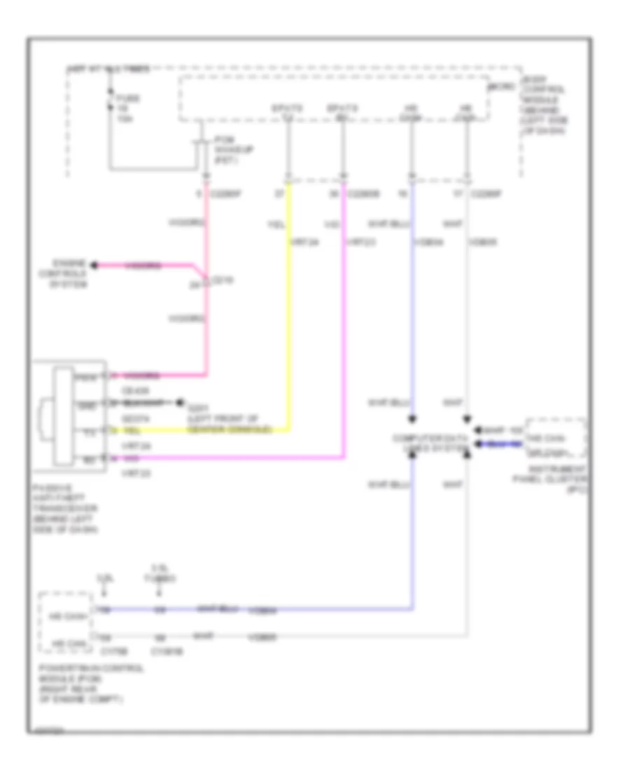
Passive Anti-theft Wiring Diagram, without Intelligent Access for Ford Flex SEL 2014
 https://portal-diagnostov.com/license.html
Automotive Electricians Portal FZCO
Automotive Electricians Portal FZCO
https://portal-diagnostov.com/license.html
https://portal-diagnostov.com/license.html
Automotive Electricians Portal FZCO
Automotive Electricians Portal FZCOList of elements for Passive Anti-theft Wiring Diagram, without Intelligent Access for Ford Flex SEL 2014:
- 3.5l
- 3.5l turbo
- Body control module (behind left side of dash)
- C1381b
- C175b
- C210
- C2280b
- C2280f
- Ce436
- Computer data lines system
- Engine controls system
- Epats rx
- Epats tx
- Fuse 10a
- G201 (left front of center console)
- Gd374
- Gnd
- Hot at all times
- Hs can+
- Hs can-
- Instrument panel cluster (ipc)
- Micro
- Passive anti-theft transceiver (behind left side of dash)
- Pcm wakeup (fet)
- Powertrain control module (pcm) (right rear of engine compt)
- Pwr
- Vdb04
- Vdb05
- Vrt23
- Vrt24
BODY CONTROL MODULES
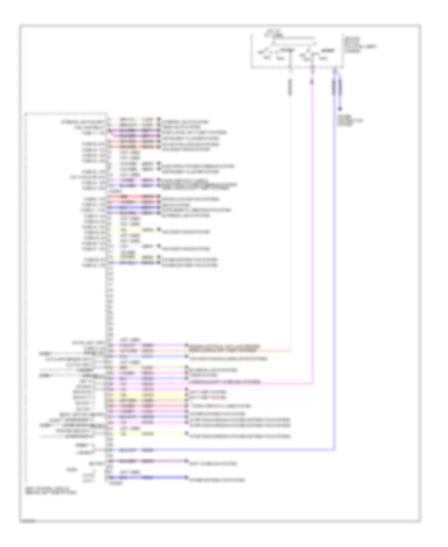
Body Control Modules Wiring Diagram (1 of 2) for Ford Flex SEL 2014
 https://portal-diagnostov.com/license.html
Automotive Electricians Portal FZCO
Automotive Electricians Portal FZCO
https://portal-diagnostov.com/license.html
https://portal-diagnostov.com/license.html
Automotive Electricians Portal FZCO
Automotive Electricians Portal FZCOList of elements for Body Control Modules Wiring Diagram (1 of 2) for Ford Flex SEL 2014:
- (not used)
- Acc
- Acc/run
- Air conditioning & headlights systems
- Air conditioning system
- Anti-theft system
- Autolamp sensor input
- Back lighting led (fet)
- Body control module (behind left side of dash)
- Bsi (fet)
- C2280a
- C2280b
- Cbp31
- Cbp34
- Cbp35
- Cbp37
- Cbp38
- Cbp41
- Ccb08
- Cdc30
- Cdc33
- Cdc34
- Cdc35
- Cet53
- Clf28
- Cls32
- Clutch input
- Computer data lines & electronic power steering systems door locks & anti-theft systems
- Computer data lines system
- Cpk35
- Cpk36
- Crh04
- Door locks, anti-theft systems
- Electronic power steering system
- Engine controls, anti-lock brakes, door locks & anti-theft systems
- Epats rx
- Epats tx
- Exterior lights system
- Fog lamp relay
- Fuse 11, 10a
- Fuse 23, 15a
- Fuse 24, 15a
- Fuse 26, 5a
- Fuse 27, 20a
- Fuse 28, 15a
- Fuse 29, 20a
- Fuse 31, 5a
- Fuse 32, 15a
- Fuse 34, 10a
- Fuse 35, 5a
- Fuse 36, 10a
- Fuse 37, 10a
- Fuse 38, 10a
- Fuse 41, 7.5a
- Fuse 42, 5a
- Fuse 44, 10a
- Fuse 45, 5a
- Fuse 46, 10a
- Fuse 9, 10a
- Hazard
- Headlights system
- Horn relay
- Horns system
- Hot at all times
- Hot in run or acc
- Ignition switch (w/o intelligent access)
- Instrument cluster system
- Interior lighting (fet)
- Interior lights system
- Key in
- Lin 01
- Lin 04
- Micro
- Ms can +
- Ms can -
- Navigation & sound systems
- Off
- Power distribution system
- Red
- Ripcord security
- Run
- Run/start
- Sbp09
- Sbp11
- Sbp23
- Sbp24
- Sbp26
- Sbp27
- Sbp29
- Sbp46
- Seats system
- Shift interlock system
- Sound & navigation systems
- Start
- Start/stop 1
- Start/stop 2
- Start/stop led (fet)
- Starting/charging & power distribution systems
- Vdb06
- Vdb07
- Vdn01
- Vlf14
- Vln04
- Vln33
- Vrt23
- Vrt24
- Warning & shift interlock systems
- White light (fet)
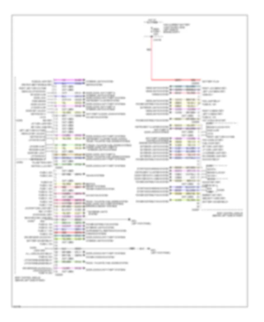
Body Control Modules Wiring Diagram (2 of 2) for Ford Flex SEL 2014
 https://portal-diagnostov.com/license.html
Automotive Electricians Portal FZCO
Automotive Electricians Portal FZCO
https://portal-diagnostov.com/license.html
https://portal-diagnostov.com/license.html
Automotive Electricians Portal FZCO
Automotive Electricians Portal FZCOList of elements for Body Control Modules Wiring Diagram (2 of 2) for Ford Flex SEL 2014:
- (not used)
- 3rd row seat enable (fet)
- All lock/unlock relay
- Anti-theft & door locks systems
- Anti-theft & engine controls systems engine controls system
- Battery plus
- Battery saver relay
- Bcs
- Body control module (behind left side of dash)
- Brake fluid sw
- Brake fluid sw rtn
- Bsi (fet)
- C1617b
- C2280c
- C2280d
- C2280e
- C2280f
- C2280g
- Cbb30
- Cbp32
- Cbp34
- Cbp41
- Cbp48
- Cdc21
- Cdc55
- Cdc64
- Cdc66
- Ce226
- Ce436
- Clf02
- Clf03
- Clf04
- Clf05
- Clf12
- Cln09
- Cln25
- Cls17
- Cls18
- Cls19
- Cls21
- Cls25
- Cls28
- Cls30
- Cmc19
- Cmc25
- Computer data lines system
- Cpk19
- Cpk23
- Cpk28
- Cpk29
- Cpk30
- Cpk31
- Cpl11
- Cpl25
- Cpl26
- Cpl31
- Cpl36
- Cpl39
- Cpl44
- Cpl45
- Cpl51
- Cpl52
- Cpl84
- Cps48
- Decklid key unlock
- Decklid/liftgate sw
- Door key lock
- Door key unlock
- Door lock
- Door locks & anti-theft systems
- Door locks, anti-theft & interior lights systems
- Door locks, anti-theft & interior lights systems door locks & anti-theft systems
- Door locks, anti-theft & trunk, tailgate, fuel doors systems door locks & anti-theft systems
- Door unlock
- Driver door unlock & all lock/unlock rly fuse 19, 20a
- Driver door unlock rly
- Energy mgt (fet)
- Exterior lights system
- Fog lamp relay
- Front led turn outage
- Fuel pump (fet)
- Fuse 1, 30a
- Fuse 2, 15a
- Fuse 21, 10a
- Fuse 3, 30a
- Fuse 30, 15a
- Fuse 31, 5a
- Fuse 32, 15a
- Fuse 33, 10a
- Fuse 34, 10a
- Fuse 4, 10a
- Fuse 40, 10a
- Fuse 41, 7.5a
- Fuse 43, 10a
- Fuse 48, 30a
- Fuse 5, 20a
- Fuse 6, 5a
- Fuse 7, 7.5a
- Fuse 8, 10a
- Fuse 9, 10a
- G301 (left kick panel)
- Gd233
- Gnd
- Headlights system
- High current battery junction box (bjb) (left side of engine compt)
- Hood ajar
- Horn rly
- Horns system
- Hot at all times
- Hot in run or start
- Hs can +
- Hs can -
- Instrument cluster system
- Instrument cluster, door locks & trunk, tailgate, fuel doors systems
- Interior lights system
- Keypad illum (fet)
- Keypad sw a
- Keypad sw b
- Keypad sw c
- Ldc59
- Left hi beam (fet)
- Left led turn outage
- Left low beam (fet)
- Lf door ajar
- Lf turn lamp (fet)
- Lh corner lamp (fet)
- Liftgate ajar
- Liftgate release relay
- Liftgate sw
- Lin 02
- Lin 03
- Logic gnd
- Lr door ajar
- Lr stop/turn lamp (fet)
- Lr turn lamp (fet)
- Mega fuse 1 100a
- Micro
- Navigation system
- Park brake
- Pcm wake up (fet)
- Power distribution system
- Power windows system
- Puddle lamp (fet)
- Pulse train (fet)
- Rdc59
- Red
- Rev lp (fet)
- Rf door ajar
- Rf turn lamp (fet)
- Rh corner lamp (fet)
- Right hi beam (fet)
- Right led turn outage
- Right low beam (fet)
- Rmc19
- Rr door ajar
- Rr stop/turn lamp (fet)
- Rr turn lamp (fet)
- Run/acc relay
- Run/start (fet)
- S305
- Sbf01
- Sbp01
- Sbp02
- Sbp05
- Sbp07
- Sbp08
- Sbp09
- Sdc57
- Seats & memory systems
- Seats system
- Security horn (fet)
- Sig rtn
- Sound systems
- Srh01
- Starting/charging system
- Stop/chmsl (fet)
- Trunk, tailgate, fuel doors system
- Trunk, tailgate, fuel doors system door locks, anti-theft systems, mirrors & memory systems
- Trunk, tailgate, fuel doors systems door locks, anti-theft & interior lights systems
- Vdb04
- Vdb05
- Vdn03
- Vref
- Warning systems
COMPUTER DATA LINES
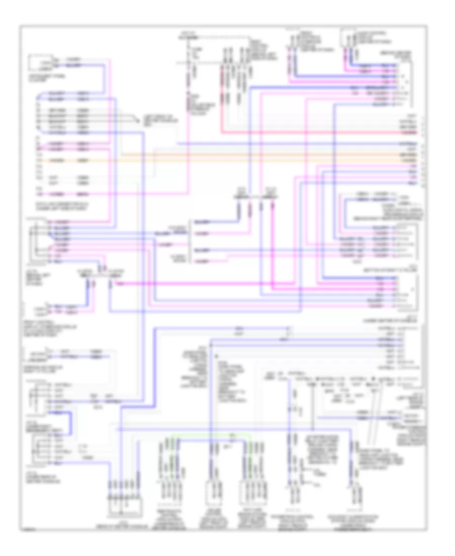
Computer Data Lines Wiring Diagram (1 of 2) for Ford Flex SEL 2014
 https://portal-diagnostov.com/license.html
Automotive Electricians Portal FZCO
Automotive Electricians Portal FZCO
https://portal-diagnostov.com/license.html
https://portal-diagnostov.com/license.html
Automotive Electricians Portal FZCO
Automotive Electricians Portal FZCOList of elements for Computer Data Lines Wiring Diagram (1 of 2) for Ford Flex SEL 2014:
- (behind center of dash) j/c 15
- (center of dash)
- (dash panel to headlamp junction wiring harness, near breakout to battery junction box)
- (left front of center console) g201
- (not used) c144
- (starter motor relay & battery ground wiring harness, near breakout to heated oxygen sensor no. 12)
- 3.5l
- 3.5l turbo
- Anti-lock brake system module (abs) (left rear of engine compt)
- Audio control module (center of dash)
- Audio digital signal processing module (behind right rear quarterpanel)
- Body control module (behind left side of dash)
- C1381b
- C144
- C175b
- C211
- C212
- C2280a
- C3050
- C310b
- Cruise control module (ccm) (left front of engine compt)
- Data link connector (dlc) (under left side of dash)
- Front control/ display interface module (w/ 4.2 inch display) (center of dash)
- Front controls interface module i can+
- Fuse 15a
- Gd374
- Hot at all times
- Hs can + c1467a
- Hs can -
- Hs can+
- Hs can-
- Hs can- c2280f
- I can+
- I can+ c240a
- I can+ c4326a
- I can-
- Instrument panel cluster
- J/c 13 (left rear of engine compt)
- J/c 14 (under rear of center console)
- J/c 16 (behind left center of dash)
- J/c 17 (under center of console)
- J/c 18 (under right second row seat)
- J/c 2 (rear of center console)
- J/c 4 (bottom of right "c" pillar)
- Ms can+ c2280b
- Ms can-
- Occupant classification system module (ocsm) (under front passenger's seat)
- Parking aid module (right "c" pillar)
- Power steering control module (pscm) (right rear of engine compt)
- Powertrain control module (pcm) (right rear of engine compt)
- Restraints control module (rcm) (under rear of center console)
- S106
- S109
- S110
- S111
- S141 (dash panel to headlamp junction wiring harness, near breakout to battery junction box)
- S142 (dash panel to headlamp junction wiring harness, near breakout to battery junction box)
- Sbp24
- Vca23
- Vca24
- Vdb04
- Vdb05
- Vdb06
- Vdb07
- Vdb13
- Vdb14
- W/ 4.2 inch display
- W/ 8 inch display
- W/ sony sound
- W/ sync gen 1
- W/ sync gen 2
- W/o sony sound
- Yaw can+
- Yaw can-
Computer Data Lines Wiring Diagram (2 of 2) for Ford Flex SEL 2014
 https://portal-diagnostov.com/license.html
Automotive Electricians Portal FZCO
Automotive Electricians Portal FZCO
https://portal-diagnostov.com/license.html
https://portal-diagnostov.com/license.html
Automotive Electricians Portal FZCO
Automotive Electricians Portal FZCOList of elements for Computer Data Lines Wiring Diagram (2 of 2) for Ford Flex SEL 2014:
- (behind left side of dash) j/c 12
- (behind left side of dash) j/c 6
- (behind left side of dash) j/c 7
- (not used)
- (top of steering column) steering column control module
- Accessory protocol interface module (behind center of dash)
- Accessory protocol interface module (w/ sync gen 2 (8 inch display)) (center console)
- Automatic a/c
- Backup transceiver (w/ 8 inch display) (under rear of center console)
- C210
- C212
- C214
- C215
- C2153e
- C219
- C228a
- C2357a
- C2365c
- C3050
- C311
- C339
- C340
- C341d
- C4174b
- Driver door module (in driver's door)
- Driver's seat module (under driver's seat)
- Dual climate controlled seat module (under front passenger's seat)
- Emtc hvac module (manual a/c) datc hvac module (automatic a/c) (right side of dash)
- Global positioning system module (behind center of dash)
- Head up display (hud) module (w/ adaptive cruise control) (top left side of dash)
- Hs can+
- Hs can-
- Hs can- c2414a
- I can+
- I can-
- Instrument panel cluster
- J/c 1 (behind left side of dash)
- J/c 10 (under passenger's seat)
- J/c 11 (behind right side of dash)
- J/c 3 (left kick panel)
- J/c 5 (behind left rear quarterpanel)
- J/c 8 (under driver's seat)
- J/c 9 (behind right rear quarterpanel)
- Left rear side obstacle detection sensor (left rear corner of vehicle)
- Liftgate trunk module (left "d" pillar)
- Manual a/c
- Manual liftgate w/o memory
- Ms can+
- Ms can+ c501b
- Ms can-
- Power liftgate w/ memory
- Remote function actuator module (behind right side of dash)
- Right rear side obstacle detection sensor (right rear corner of vehicle)
- Tire pressure monitor module (right front of roof)
- Vdb04
- Vdb05
- Vdb06
- Vdb07
- Vdb13
- Vdb14
- W/ ddm
- W/ heated/cooled seats
- W/ sync
- W/ sync gen 1
- W/ sync gen 2
- W/o ddm
- W/o sync
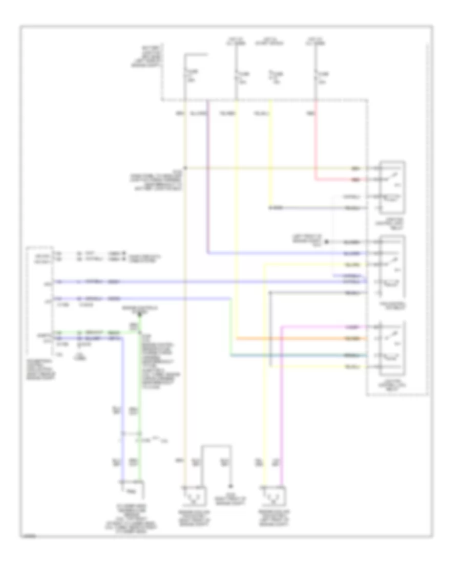
COOLING FAN
Cooling Fan Wiring Diagram for Ford Flex SEL 2014
 https://portal-diagnostov.com/license.html
Automotive Electricians Portal FZCO
Automotive Electricians Portal FZCO
https://portal-diagnostov.com/license.html
https://portal-diagnostov.com/license.html
Automotive Electricians Portal FZCO
Automotive Electricians Portal FZCOList of elements for Cooling Fan Wiring Diagram for Ford Flex SEL 2014:
- (left front of engine compt) g101
- 3.5l
- 3.5l turbo
- Battery junction box (bjb) (left side of engine compt)
- C1381b
- C1381e
- C175b
- C175e
- C192
- Cec01
- Cec02
- Cht
- Computer data lines system
- Cylinder head temperature sensor (3.5l: top front of right cylinder head) (3.5l turbo: rear of right cylinder head)
- Engine controls system
- Engine cooling fan motor 1 (right front of engine compt)
- Engine cooling fan motor 2 (left front of engine compt)
- Fan control (fc) relay
- Fuse 15a
- Fuse 25a
- Fuse 40a
- G100 (right front of engine compt)
- Hfc
- High fan control (hfc) relay
- Hot at all times
- Hot in start or run
- Hs can +
- Hs can -
- Lfc
- Low fan control (lfc) relay
- Powertrain control module (pcm) (right rear of engine compt)
- Re405
- Red
- S108
- S122 (dash panel to headlamp junction wiring harness, near breakout to battery junction box)
- S126 (3.5l: engine control sensor & fuel charge wiring harness, near breakout to fuel injector 3) (3.5l turbo: engine wiring harness, near breakout to c1045)
- Sigrtn
- Vdb04
- Vdb05
- Ve712
CRUISE CONTROL
Cruise Control Wiring Diagram for Ford Flex SEL 2014
 https://portal-diagnostov.com/license.html
Automotive Electricians Portal FZCO
Automotive Electricians Portal FZCO
https://portal-diagnostov.com/license.html
https://portal-diagnostov.com/license.html
Automotive Electricians Portal FZCO
Automotive Electricians Portal FZCOList of elements for Cruise Control Wiring Diagram for Ford Flex SEL 2014:
- (engine wiring harness, in breakout to c168 on transmission) s100
- (right front of center console) g200
- (top front of left cylinder head) g106
- (under left side of dash) brake pedal position (bpp) switch
- (under steering wheel) clock spring
- 3.5l
- 3.5l turbo
- 6f50/6f55 transmission (left side of transmission)
- A/d 2
- A/d 3
- A/d 4
- Accelerator pedal position (app) sensor (under left side of dash)
- App1
- App2
- Apprtn1
- Apprtn2
- Appverf2
- Appvref1
- Battery junction box (bjb) (left side of engine compt)
- Body control module (bcm) (behind left side of dash)
- Bpp
- Bps
- C1381b
- C1381e
- C1609a
- C1609b
- C175b
- C175e
- C175t
- C210
- C2153c
- C2153e
- C218b
- C218c
- C2280a
- C2414a
- Cbb90
- Cbb91
- Ccb08
- Ce412
- Ce426
- Ces09
- Cncl
- Computer data lines system
- Cruise control module (w/ adaptive cruise control) (left front of engine compt)
- Electronic throttle control (etc) (on throttle body)
- Engine controls system
- Etcref
- Etcrtn
- Exterior lights system
- Fuse 10a
- Fuse 15a
- G100 (right front of engine compt)
- G102 (right rear of engine compt)
- Gap+
- Gap-
- Gd113
- Gd123
- Gd375
- Gnd
- Head up display (hud) module (w/ adaptive cruise control) (top left side of dash)
- Hot at all times
- Hot in run or start
- Hot in start or run
- Hs can +
- Hs can -
- Hs can+
- Hs can-
- Instrument panel cluster (ipc)
- Interior lights system
- Isp-r
- Le111
- Le134
- Le136
- Le137
- Left steering wheel switch
- Logic gnd
- Lt sw gnd
- Ms can+
- Ms can-
- Nca
- Off
- On/off
- Oss
- Powertrain control module (right rear of engine compt)
- Pwrgnd
- Re134
- Re136
- Re137
- Remote function actuator (rfa) module (w/ intelligent access) (behind right side of dash)
- Res
- Res/ cncl
- Ret04
- Ret24
- Ret33
- Right steering wheel switch
- S107 (3.5l turbo) (engine wiring harness, near breakout to c1045)
- S130
- S204 (w/ intelligent access) (main wiring harness, near breakout to c210)
- S206
- S221 (in steering wheel)
- S295 (in steering wheel)
- S296 (in steering wheel)
- Sbb79
- Sbp23
- Set+
- Set-
- Steering column control module (sccm) (top of steering column)
- Tacm+
- Tacm-
- Tp1
- Tp2
- Tss
- Tss/oss gnd
- Tss/oss vpwr
- Tss/oss/tr gnd
- Vbatt
- Vdb04
- Vdb05
- Vdb06
- Vdb07
- Ve701
- Ve702
- Ve818
- Ve819
- Vpwr
- W/ adaptive cruise control
- W/o adaptive cruise control
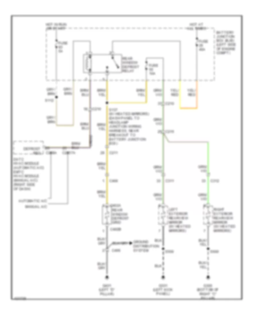
DEFOGGERS
Defoggers Wiring Diagram for Ford Flex SEL 2014
 https://portal-diagnostov.com/license.html
Automotive Electricians Portal FZCO
Automotive Electricians Portal FZCO
https://portal-diagnostov.com/license.html
https://portal-diagnostov.com/license.html
Automotive Electricians Portal FZCO
Automotive Electricians Portal FZCOList of elements for Defoggers Wiring Diagram for Ford Flex SEL 2014:
- Automatic a/c
- Battery junction box (bjb) (left side of engine compt)
- C210
- C211
- C215
- C228a
- C2357a
- C311
- C312
- C402a
- C402b
- C406
- Crd02
- Datc hvac module (automatic a/c) emtc hvac module (manual a/c) (right side of dash)
- Defrost req
- Fuse 10a
- Fuse 40a
- Fuse 5a
- G300 (bottom of right "c" pillar)
- G301 (left kick panel)
- G401 (left "d" pillar)
- Ground distribution system
- Hot at all times
- Hot in run or start
- Left exterior rearview mirror (w/ heated mirrors)
- Manual a/c
- Rear window defrost grid
- Rear window defrost relay
- Right exterior rearview mirror (w/ heated mirrors)
- S112
- S500
- S600
ELECTRONIC POWER STEERING
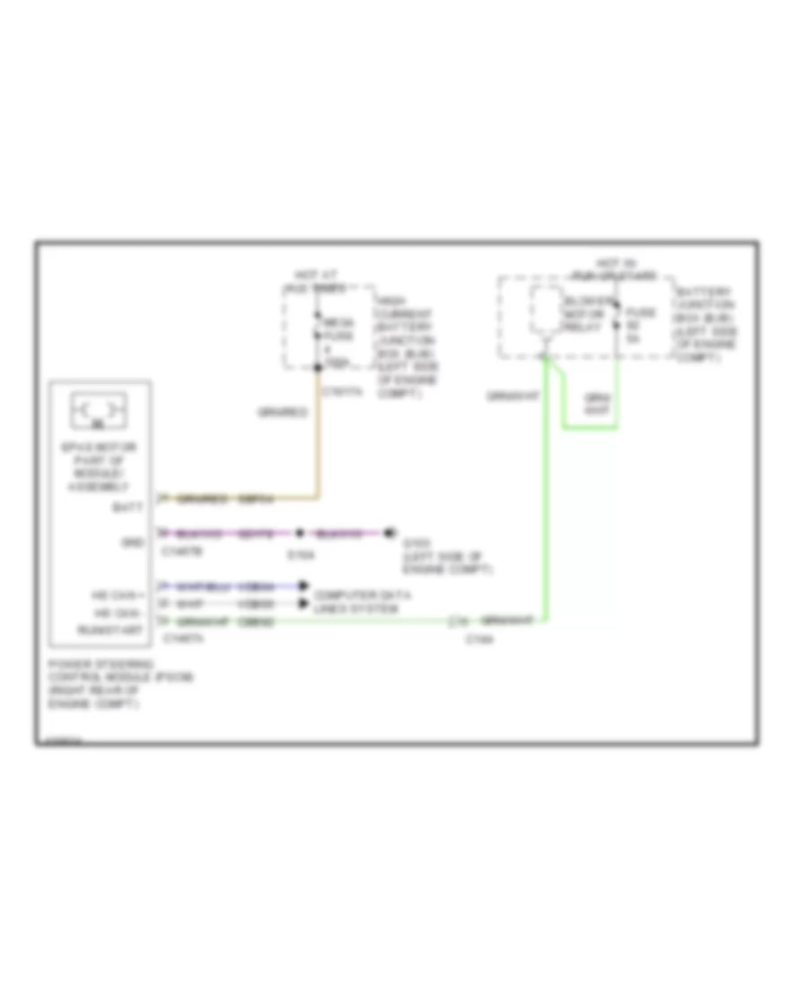
Electronic Power Steering Wiring Diagram for Ford Flex SEL 2014
 https://portal-diagnostov.com/license.html
Automotive Electricians Portal FZCO
Automotive Electricians Portal FZCO
https://portal-diagnostov.com/license.html
https://portal-diagnostov.com/license.html
Automotive Electricians Portal FZCO
Automotive Electricians Portal FZCOList of elements for Electronic Power Steering Wiring Diagram for Ford Flex SEL 2014:
- Batt
- Battery junction box (bjb) (left side of engine compt)
- Blower motor relay
- C144
- C1467a
- C1467b
- C1617a
- Cbb92
- Computer data lines system
- Epas motor part of module/ assembly
- Fuse 5a
- G103 (left side of engine compt)
- Gd178
- Gnd
- High current battery junction box (bjb) (left side of engine compt)
- Hot at all times
- Hot in run or start
- Hs can +
- Hs can -
- Mega fuse 100a
- Power steering control module (pscm) (right rear of engine compt)
- Run/start
- S104
- Sbf04
- Vdb04
- Vdb05
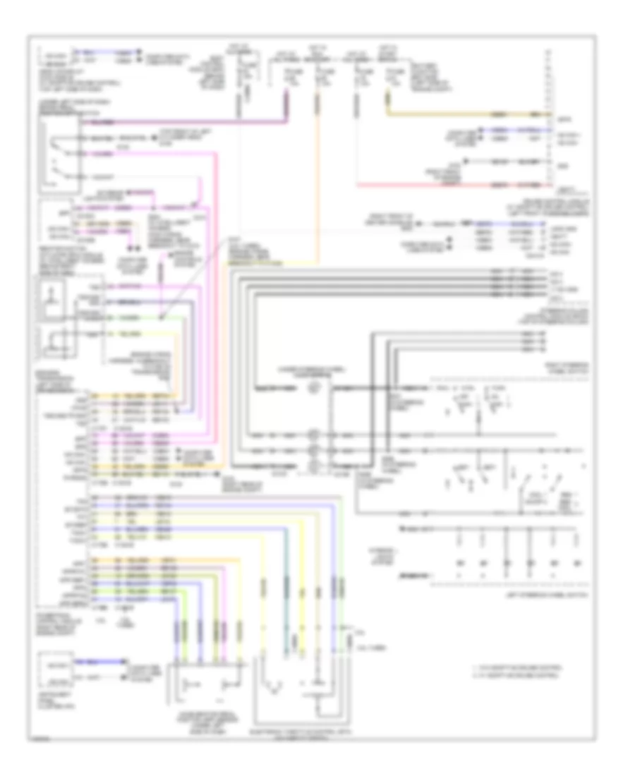
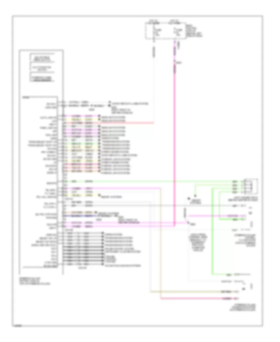
Power Steering Column Wiring Diagram for Ford Flex SEL 2014
 https://portal-diagnostov.com/license.html
Automotive Electricians Portal FZCO
Automotive Electricians Portal FZCO
https://portal-diagnostov.com/license.html
https://portal-diagnostov.com/license.html
Automotive Electricians Portal FZCO
Automotive Electricians Portal FZCOList of elements for Power Steering Column Wiring Diagram for Ford Flex SEL 2014:
- (main wiring harness, near breakout to accessory protocol interface module)
- A/d 1
- A/d 2
- A/d 3
- A/d 4
- Adj pdl mtr (fwd)
- Adjustable pedal switch
- Auto lamp on
- Body control module (behind left side of dash)
- C2280a
- C2414a
- C2414b
- C2414d
- Cet42
- Cet43
- Clf19
- Clf21
- Clf23
- Clf24
- Cln55
- Cln56
- Cls34
- Com mtr
- Computer data lines system
- Cpp01
- Cpp04
- Cpp05
- Cpp22
- Crh04
- Cruise control system
- Crw15
- Dim down
- Dim sw gnd
- Dim up
- Dome lp
- Fog lamp
- Frt wiper hi
- Fuse 15a
- G200 (right front of center console)
- Gd375
- Headlights system
- Horn
- Horn sw
- Horns system
- Hot at all times
- Hs can +
- Hs can -
- Instrument cluster system
- Interior lights system
- Joint connector 24 (behind center of dash)
- Lf sw gnd
- Lin
- Logic gnd
- Low
- Lpp06
- Memory systems
- Micro
- Multi-function switch
- Navigation & sound systems
- Nca
- Off
- Park lamp on
- Pdl hall sns sig
- Pwr gnd
- Re407
- Rh sw gnd
- Rln29
- Rpp06
- Rtn sig
- S202
- S206
- S212
- Sbp23
- Sbp24
- Select sw down
- Select sw up
- Signal return cowl
- Sns rtn
- Steering column control module (top of steering column)
- Steering column control tilting motor (top of steering column)
- Steering column telescoping motor (on steering column)
- Steering wheel angle sensor
- Tel mtr +/-
- Tel sns +
- Tilt mtr +/-
- Tilt sns +
- Trans select shift dw
- Trans select shift up
- Transmissions system
- Vbatt
- Vdb04
- Vdb05
- Vdn05
- Vln36
- Vpp08
- Vpp17
- Wiper/washer system
ENGINE PERFORMANCE
3.5L
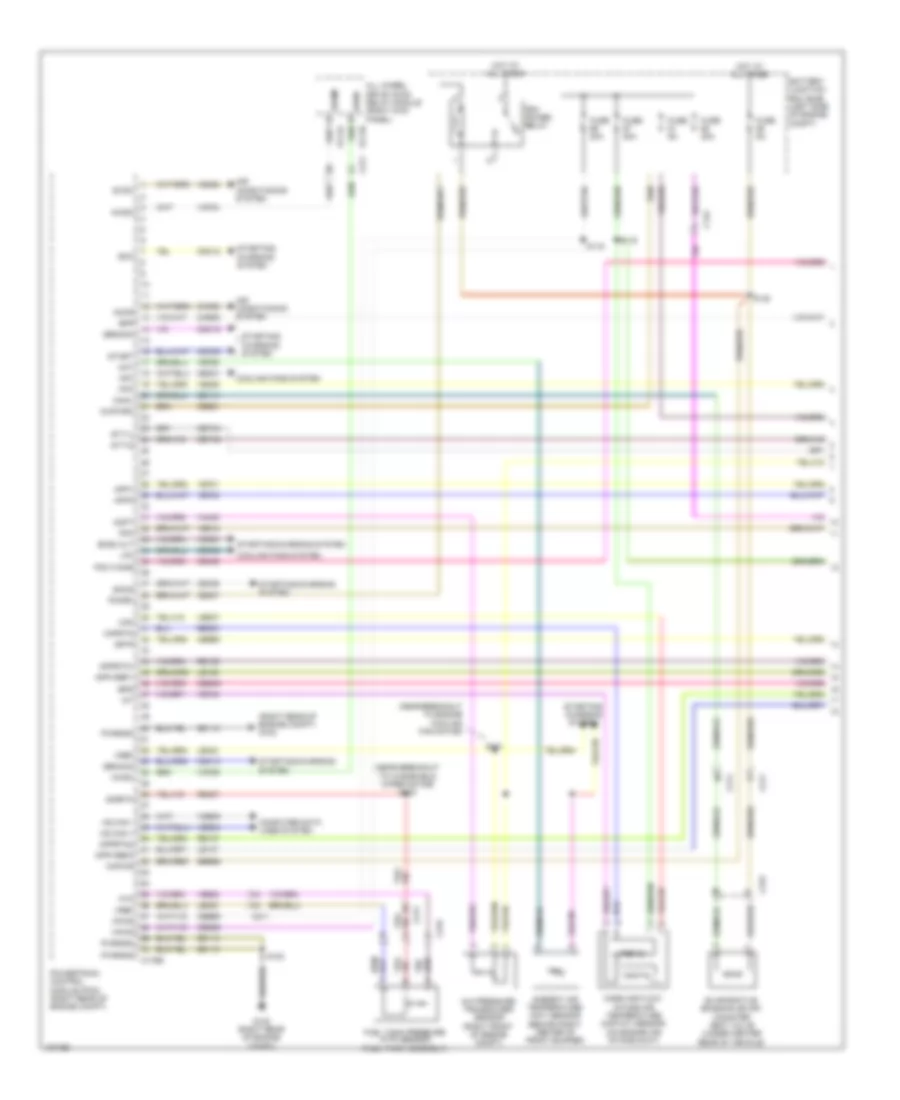
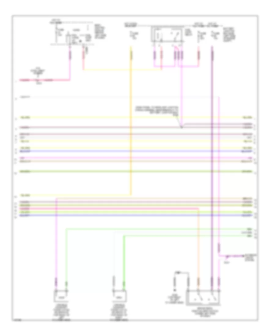
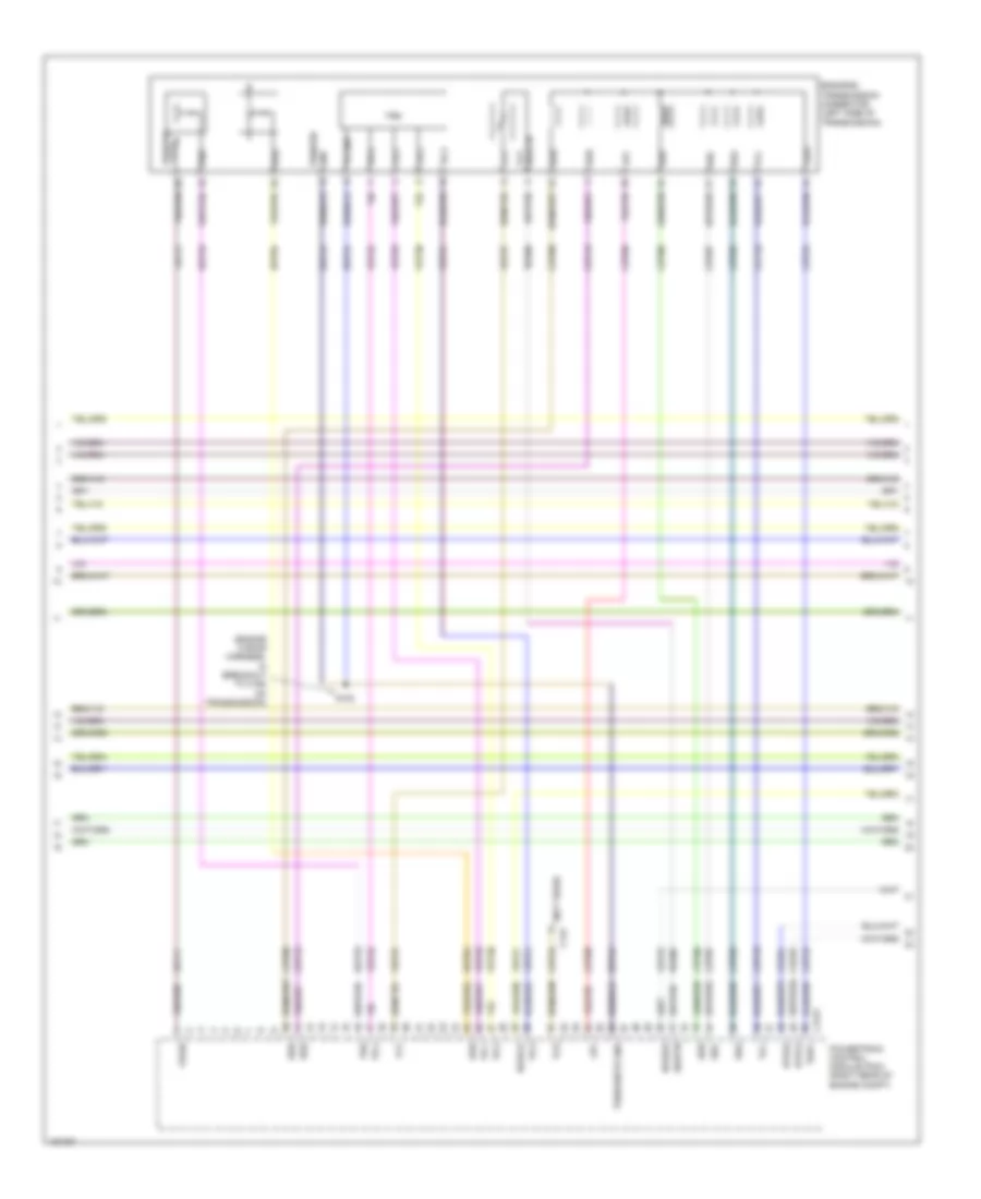
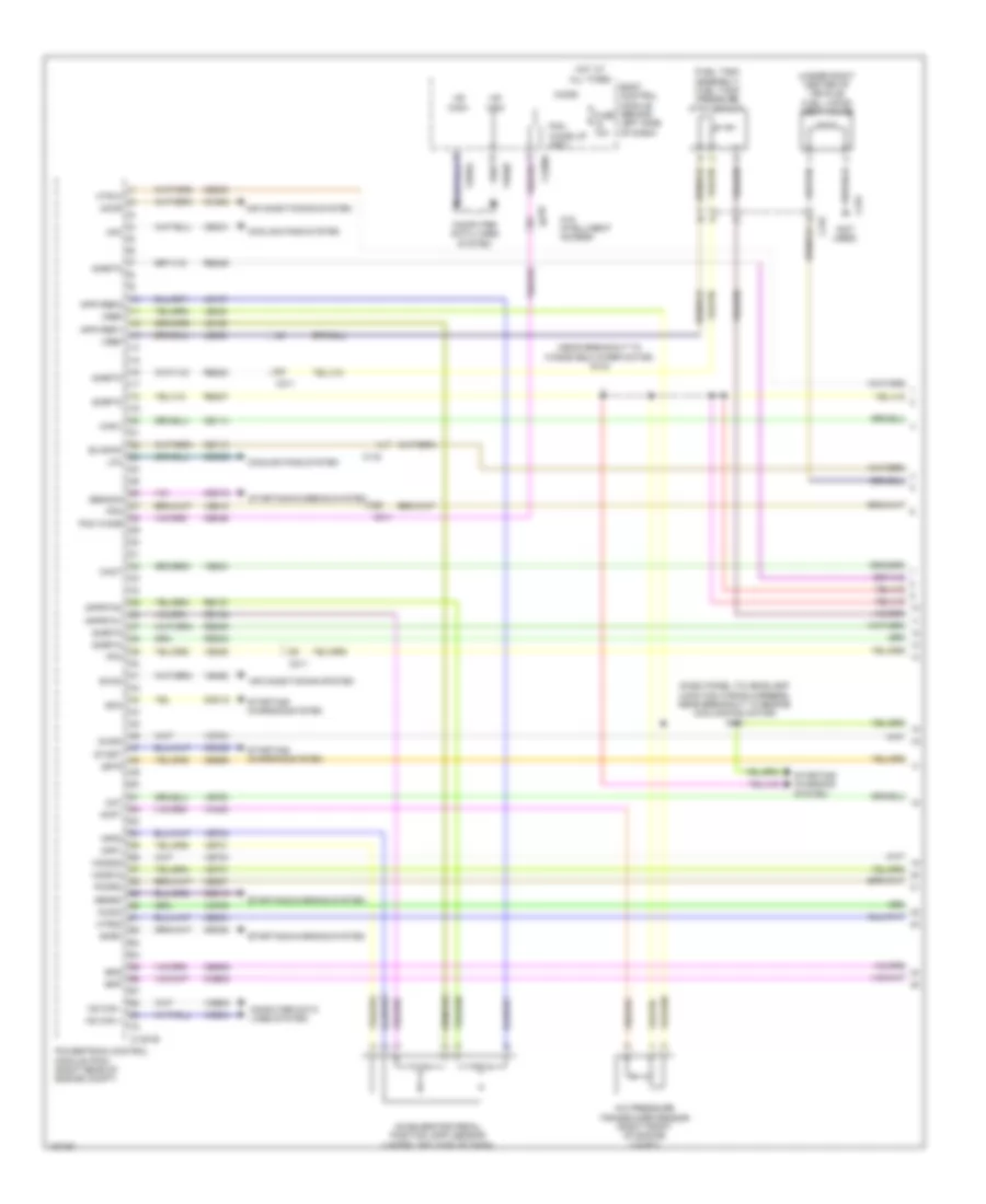
3.5L, Engine Performance Wiring Diagram (1 of 6) for Ford Flex SEL 2014
 https://portal-diagnostov.com/license.html
Automotive Electricians Portal FZCO
Automotive Electricians Portal FZCO
https://portal-diagnostov.com/license.html
https://portal-diagnostov.com/license.html
Automotive Electricians Portal FZCO
Automotive Electricians Portal FZCOList of elements for 3.5L, Engine Performance Wiring Diagram (1 of 6) for Ford Flex SEL 2014:
- (near breakout to engine cooling fan motor)
- (near breakout to windshield wiper motor) s133
- (right rear of engine compt) g102
- A/c pressure transducer sensor (right front of engine compt)
- Aat
- Accr
- Acpt
- Air conditioning system
- All wheel drive (awd) relay module (right kick panel)
- Ambient air temperature (aat) sensor (behind right center of front bumper)
- App1
- App2
- Apprtn1
- Apprtn2
- Appvref1
- Appvref2
- Awdc
- Awdm
- Battery junction box (bjb) (left side of engine compt)
- Bcs2 alt
- Bpp
- Bps
- C134
- C175b
- C211
- C315
- Canv
- Cbb51
- Cbb69
- Cbb90
- Ccb08
- Cdc10
- Cdc12
- Cdc15
- Cdc35
- Ce114
- Ce237
- Ce336
- Ce436
- Cec01
- Cec02
- Ces09
- Cet42
- Cet43
- Ch302
- Computer data lines system
- Cooling fans system
- Digital
- Evaporative emission (evap) canister vent valve (under center rear of vehicle)
- Evdc
- Fpc
- Fpm
- Ftp
- Fuel tank pressure (ftp) sensor (fuel tank assembly)
- Fuse 20a
- Fuse 5a
- G102 (right rear of engine compt)
- Gd113
- Gencom
- Genmon
- Hfc
- Hot at all times
- Hs can +
- Hs can -
- Iat
- Injpwrm
- Isp-r
- Kapwr
- Le136
- Le137
- Le230
- Le424
- Lfc
- Maf
- Mafrtn
- Mass air flow/ intake air temperature (maf/iat) sensor (on engine air intake duct)
- Pcm power relay
- Pcm wake
- Pcmrc
- Powertrain control module (pcm) (right rear of engine compt)
- Pwrgnd
- Re136
- Re137
- Re320
- Re407
- S101
- S115
- S116
- S130
- S138
- Sbb86
- Sigrtn
- Smc
- Smcs
- Start
- Starting/ charging system
- Starting/charging system
- Stt-d
- Stt-u
- Vcf34
- Vcf35
- Vdb04
- Vdb05
- Vdc61
- Ve225
- Ve462
- Ve518
- Ve701
- Ve702
- Ve740
- Ve750
- Ve807
- Ve922
- Vh433
- Vpwr
- Vref
- Vref 5v
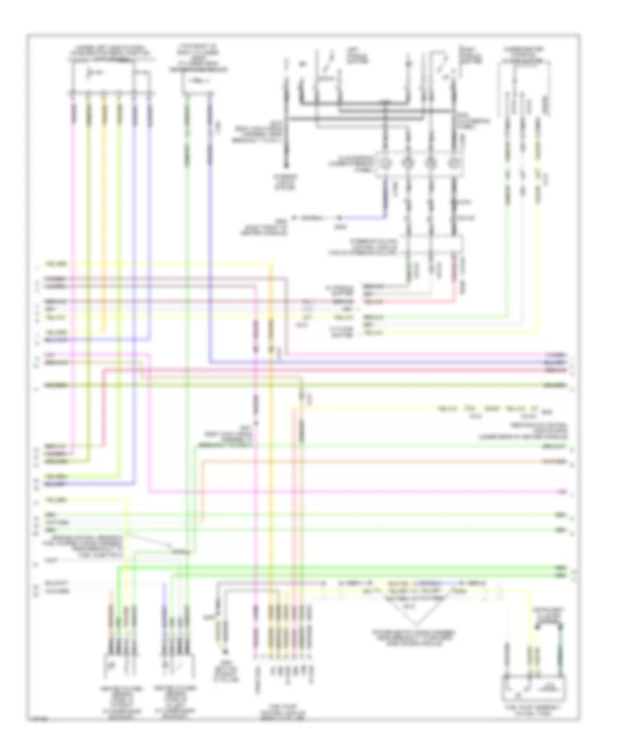
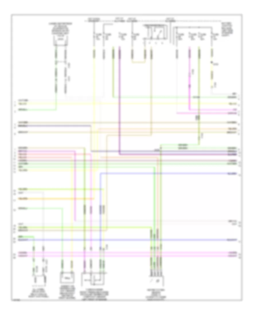
3.5L, Engine Performance Wiring Diagram (2 of 6) for Ford Flex SEL 2014
 https://portal-diagnostov.com/license.html
Automotive Electricians Portal FZCO
Automotive Electricians Portal FZCO
https://portal-diagnostov.com/license.html
https://portal-diagnostov.com/license.html
Automotive Electricians Portal FZCO
Automotive Electricians Portal FZCOList of elements for 3.5L, Engine Performance Wiring Diagram (2 of 6) for Ford Flex SEL 2014:
- (dash panel to headlamp junction wiring harness, near breakout to battery junction box) s136
- Battery junction box (bjb) (left side of engine compt)
- Body control module (behind left side of dash)
- Brake pedal position (bpp) switch (under left side of dash)
- C210
- C2280f
- Exterior lights system
- Fuel pump (fet)
- Fuel pump relay
- Fuse 10a
- Fuse 30a
- G106 (top front of left cylinder head)
- Hot at all times
- Hot in run or start
- Micro
- Pcm wake up (fet)
- S130
- Variable camshaft timing (vct12) solenoid 12 (top front of right cylinder head)
- Variable camshaft timing (vct22) solenoid 22 (top front of left cylinder head)
- W/o intelligent access
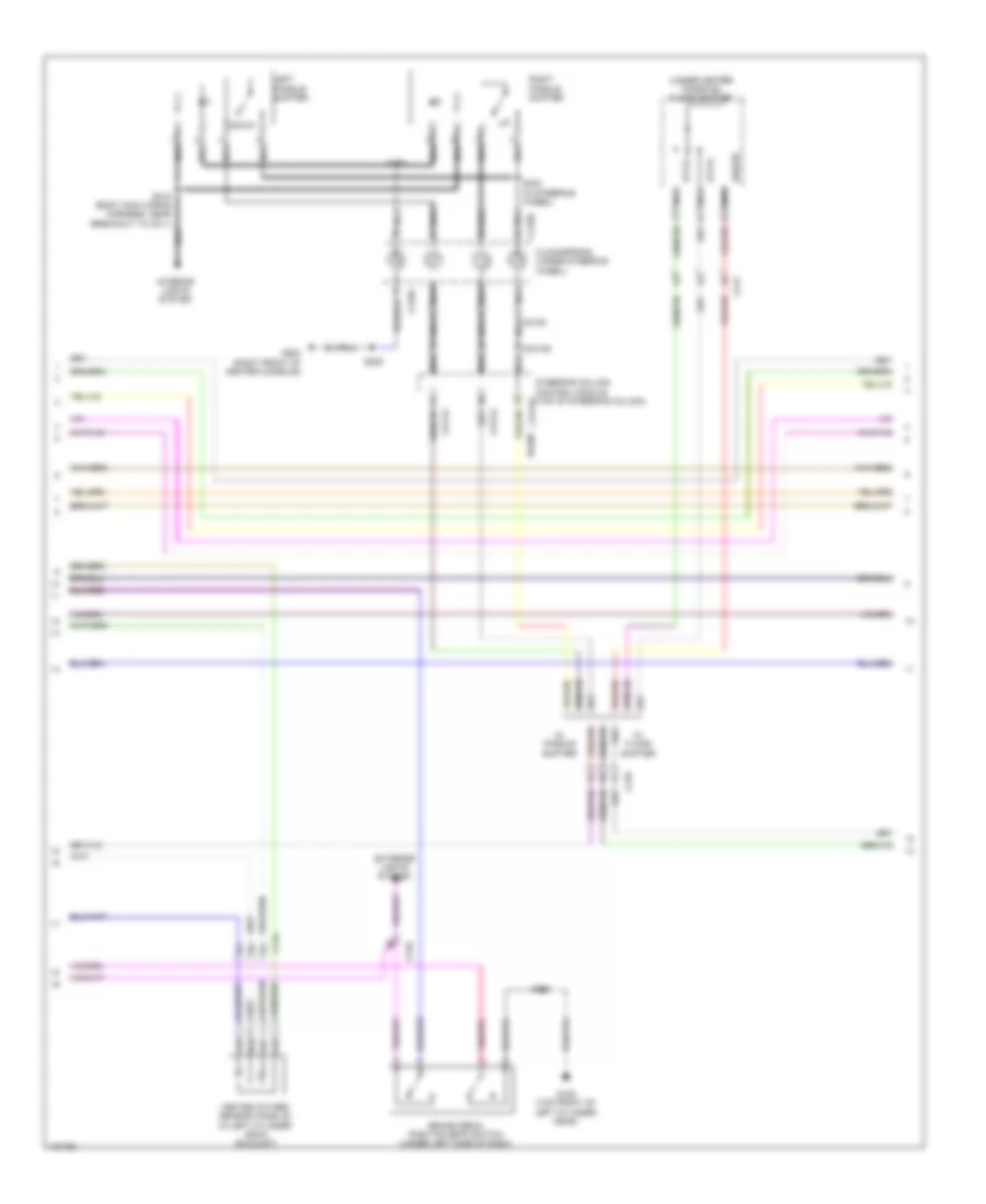
3.5L, Engine Performance Wiring Diagram (3 of 6) for Ford Flex SEL 2014
 https://portal-diagnostov.com/license.html
Automotive Electricians Portal FZCO
Automotive Electricians Portal FZCO
https://portal-diagnostov.com/license.html
https://portal-diagnostov.com/license.html
Automotive Electricians Portal FZCO
Automotive Electricians Portal FZCOList of elements for 3.5L, Engine Performance Wiring Diagram (3 of 6) for Ford Flex SEL 2014:
- (engine wiring harness, in breakout to c168 on transmission)
- (not used)
- 6f50/6f55 transmission connector (left side of transmission)
- C134
- C175t
- Ce233
- Ce234
- Cet05
- Cet06
- Cet07
- Cet08
- Cet09
- Cet10
- Cet19
- Cet25
- Cet34
- Gnd tss/oss
- Ho2s12
- Ho2s22
- Htr12
- Htr22
- Le111
- Lpc
- Oss
- Powertrain control module (pcm) (right rear of engine compt)
- Re406
- Ret04
- Ret24
- Ret33
- S100
- Sigrtn
- Sigrtn tft
- Ssa
- Ssb
- Ssc
- Ssd
- Sse
- Tcc
- Tcs
- Tft
- Tr gnd
- Tr-1
- Tr-2
- Tr-3
- Tr-4
- Trs
- Tspc
- Tss
- Tss/oss/tr gnd
- Ve731
- Ve733
- Vet27
- Vet29
- Vet30
- Vet31
- Vet32
- Vpwr
- Vpwr tss/oss
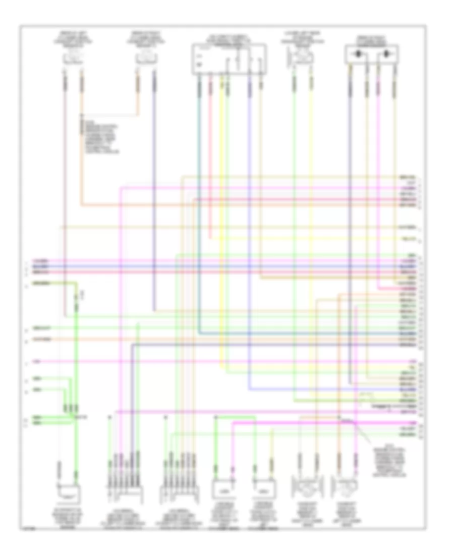
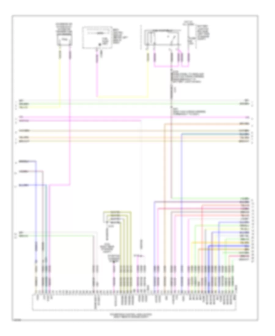
3.5L, Engine Performance Wiring Diagram (4 of 6) for Ford Flex SEL 2014
 https://portal-diagnostov.com/license.html
Automotive Electricians Portal FZCO
Automotive Electricians Portal FZCO
https://portal-diagnostov.com/license.html
https://portal-diagnostov.com/license.html
Automotive Electricians Portal FZCO
Automotive Electricians Portal FZCOList of elements for 3.5L, Engine Performance Wiring Diagram (4 of 6) for Ford Flex SEL 2014:
- (engine control sensor & fuel charge wiring harness, near breakout to fuel injector 3)
- (power seats wiring harness, near breakout to driver's side air bag module)
- (top front of right cylinder head) cylinder head temperature sensor
- (under center console) floor shifter
- (under left side of dash) accelerator pedal position (app) sensor
- C192
- C210
- C211
- C212
- C214
- C218a
- C218b
- C218c nca
- C2414a
- C2414d
- C310a
- C315
- Ce515
- Ce608
- Cet42
- Cet43
- Clockspring (under steering wheel)
- Cr167
- Down
- Ens
- Fp pwr
- Fp rtn
- Fpc
- Fpm
- Fuel pump assembly (in fuel tank)
- Fuel pump control module (right "c" pillar)
- G200 (right front of center console)
- G300 (bottom of right "c" pillar)
- Gd348
- Gnd
- Heated oxygen sensor (ho2s) 12 (in right cylinder bank exhaust)
- Heated oxygen sensor (ho2s) 22 (in left cylinder bank exhaust)
- Instrument cluster system
- Interior lights system
- Left paddle shifter
- Nca
- Re407
- Re515
- Restraints control module (rcm) (under rear of center console)
- Right paddle shifter
- S126
- S206
- S215 (body main wiring harness, near breakout to c211)
- S242 (in steering wheel)
- S299
- S302
- S311
- S401 (body main wiring harness, in breakout to c3041)
- S405
- Sigrtn
- Steering column control module (top of steering column)
- Stt-d
- Stt-u
- Ve225
- Ve518
- Vpwr fuel
- W/ floor shifter
- W/ paddle shifter
3.5L, Engine Performance Wiring Diagram (5 of 6) for Ford Flex SEL 2014
 https://portal-diagnostov.com/license.html
Automotive Electricians Portal FZCO
Automotive Electricians Portal FZCO
https://portal-diagnostov.com/license.html
https://portal-diagnostov.com/license.html
Automotive Electricians Portal FZCO
Automotive Electricians Portal FZCOList of elements for 3.5L, Engine Performance Wiring Diagram (5 of 6) for Ford Flex SEL 2014:
- (lower left rear of engine) crankshaft position sensor
- (on throttle body) electronic throttle control (etc)
- (rear of left cylinder head) camshaft position sensor 22
- (rear of right cylinder head) camshaft position sensor 12
- (rear of right cylinder head) knock sensor
- C134
- Camshaft position sensor 11 (rear of right cylinder head)
- Camshaft position sensor 21 (rear of left cylinder head)
- Evaporative emission (evap) purge valve (top rear of engine)
- Nca
- S121 (engine control sensor & fuel charge wiring harness, near breakout to powertrain control module)
- S123
- S125 (engine control sensor & fuel charge wiring harness, near breakout to powertrain control module)
- S146
- Tan
- Universal heated oxygen sensor (ho2s) 11 (in right cylinder bank exhaust manifold)
- Universal heated oxygen sensor (ho2s) 21 (in left cylinder bank exhaust manifold)
- Variable camshaft timing (vct11) solenoid 11 (top front of right cylinder head)
- Variable camshaft timing (vct21) solenoid 21 (top front of left cylinder head)
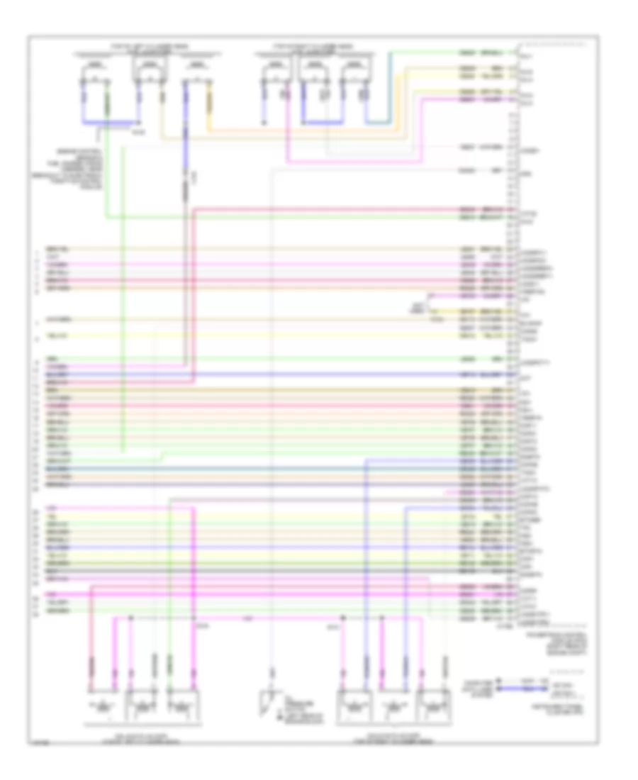
3.5L, Engine Performance Wiring Diagram (6 of 6) for Ford Flex SEL 2014
 https://portal-diagnostov.com/license.html
Automotive Electricians Portal FZCO
Automotive Electricians Portal FZCO
https://portal-diagnostov.com/license.html
https://portal-diagnostov.com/license.html
Automotive Electricians Portal FZCO
Automotive Electricians Portal FZCOList of elements for 3.5L, Engine Performance Wiring Diagram (6 of 6) for Ford Flex SEL 2014:
- (engine control sensor & fuel charge wiring harness, near breakout to electronic throttle control module)
- (not used)
- (top of left cylinder head) fuel injectors
- (top of right cylinder head) fuel injectors
- C134
- C175e
- Ce113
- Ce205
- Ce206
- Ce207
- Ce208
- Ce209
- Ce210
- Ce235
- Ce236
- Ce303
- Ce304
- Ce305
- Ce306
- Ce307
- Ce308
- Ce412
- Ce421
- Ce422
- Ce426
- Ce442
- Ce443
- Cht
- Ckp+
- Ckp-
- Cmc24
- Cmp11
- Cmp12
- Cmp21
- Cmp22
- Coils on plug (cop) (top of left cylinder head)
- Coils on plug (cop) (top of right cylinder head)
- Computer data lines system
- Cop1a
- Cop2c
- Cop3e
- Cop4b
- Cop5d
- Cop6f
- De135
- Etcref
- Etcrtn
- Evapcp
- Hs can +
- Hs can -
- Inj-1
- Inj-2
- Inj-3
- Inj-4
- Inj-5
- Inj-6
- Instrument panel cluster (ipc)
- Ks1+
- Ks1-
- Ks2+
- Ks2-
- Le134
- Le448
- Le449
- Le450
- Le451
- Le452
- Le453
- Lfc
- Oil pressure switch (left rear of engine block)
- Ops
- Powertrain control module (pcm) (right rear of engine compt)
- Re134
- Re135
- Re323
- Re324
- Re405
- Re429
- S124
- S131
- S145
- Shdrtn
- Sigrtn
- Tacm+
- Tacm-
- Tft
- Tp1
- Tp2
- Uo2s11
- Uo2s21
- Uo2sgref11
- Uo2sgref21
- Uo2shtr11
- Uo2shtr21
- Uo2spc11
- Uo2spc21
- Uo2spct11
- Uo2spct21
- Vct11
- Vct12
- Vct21
- Vct22
- Ve706
- Ve707
- Ve711
- Ve712
- Ve740
- Ve801
- Ve802
- Ve818
- Ve819
- Ve826
- Ve827
- Vet27
- Vrsrtn
- Vrsrtn2
3.5L TURBO
3.5L Turbo, Engine Performance Wiring Diagram (1 of 7) for Ford Flex SEL 2014
 https://portal-diagnostov.com/license.html
Automotive Electricians Portal FZCO
Automotive Electricians Portal FZCO
https://portal-diagnostov.com/license.html
https://portal-diagnostov.com/license.html
Automotive Electricians Portal FZCO
Automotive Electricians Portal FZCOList of elements for 3.5L Turbo, Engine Performance Wiring Diagram (1 of 7) for Ford Flex SEL 2014:
- (dash panel to headlamp junction wiring harness, near breakout to engine cooling fan motor) s101
- (fuel tank assembly) fuel tank pressure (ftp) sensor
- (near breakout to windshield wiper motor) s133
- (not used)
- (under right center of vehicle) fuel vapor vent valve
- A/c pressure transducer sensor (right front of engine compt)
- Aat
- Accelerator pedal position (app) sensor (under left side of dash)
- Accr
- Acpt
- Air conditioning system
- App1
- App2
- Apprtn1
- Apprtn2
- Appvref1
- Appvref2
- Awdc
- Awdm
- Body control module (behind left side of dash)
- Bpp
- Bps
- C134
- C1381b
- C210
- C211
- C2280f
- C315
- Cact
- Canv
- Cbb90
- Ccb08
- Cdc10
- Cdc12
- Cdc15
- Cdc35
- Ce113
- Ce114
- Ce233
- Ce234
- Ce237
- Ce336
- Ce436
- Cec01
- Cec02
- Ces09
- Ch302
- Computer data lines system
- Cooling fans system
- Evapcp
- Evdc
- Fpc
- Fpm
- Fuse 10a
- Genmon
- Genrc
- Hfc
- Ho2s12
- Ho2s22
- Hot at all times
- Hs can +
- Hs can -
- Hs can+
- Hs can-
- Htr12
- Htr22
- Isp-r
- Le136
- Le137
- Le230
- Le424
- Lfc
- Micro
- Pcm wake
- Pcm wake up (fet)
- Pcmrc
- Powertrain control module (pcm) (right rear of engine compt)
- Re136
- Re137
- Re230
- Re242
- Re249
- Re406
- Re407
- Sigrtn
- Smc
- Smrc
- Start
- Starting/ charging system
- Starting/charging system
- Vcf34
- Vcf35
- Vdb04
- Vdb05
- Ve225
- Ve462
- Ve518
- Ve701
- Ve702
- Ve731
- Ve733
- Ve750
- Ve804
- Vh433
- Vref
- W/o intelligent access
3.5L Turbo, Engine Performance Wiring Diagram (2 of 7) for Ford Flex SEL 2014
 https://portal-diagnostov.com/license.html
Automotive Electricians Portal FZCO
Automotive Electricians Portal FZCO
https://portal-diagnostov.com/license.html
https://portal-diagnostov.com/license.html
Automotive Electricians Portal FZCO
Automotive Electricians Portal FZCOList of elements for 3.5L Turbo, Engine Performance Wiring Diagram (2 of 7) for Ford Flex SEL 2014:
- (under center rear of vehicle) evaporative emission (evap) canister vent valve
- All wheel drive (awd) relay module (right kick panel)
- Ambient air temperature (aat) sensor (behind right center of front bumper)
- Awdc
- Awdm
- Battery junction box (bjb) (left side of engine compt)
- C134
- C144
- C211
- C315
- Fuse 10a
- Fuse 15a
- Fuse 20a
- Fuse 5a
- Heated oxygen sensor (ho2s) 12 (in right cylinder bank exhaust)
- Hot at all times
- Hot in run or start
- Pcm power relay
- S108
- S115
- S120
- Turbocharger boost pressure/charge air cooler temperature (tcbp/cact) sensor (left front of engine)
- Vcf34
- Vcf35
3.5L Turbo, Engine Performance Wiring Diagram (3 of 7) for Ford Flex SEL 2014
 https://portal-diagnostov.com/license.html
Automotive Electricians Portal FZCO
Automotive Electricians Portal FZCO
https://portal-diagnostov.com/license.html
https://portal-diagnostov.com/license.html
Automotive Electricians Portal FZCO
Automotive Electricians Portal FZCOList of elements for 3.5L Turbo, Engine Performance Wiring Diagram (3 of 7) for Ford Flex SEL 2014:
- (under center console) floor shifter
- Brake pedal position (bpp) switch (under left side of dash)
- C144
- C210
- C214
- C218a
- C218b
- C218c
- C2414a
- C2414d
- Cet42
- Cet43
- Clockspring (under steering wheel)
- Down
- Exterior lights system
- G106 (top front of left cylinder head)
- G200 (right front of center console)
- Heated oxygen sensor (ho2s) 22 (in left cylinder bank exhaust)
- Interior lights system
- Left paddle shifter
- Nca
- Re406
- Right paddle shifter
- S130
- S206
- S215 (body main wiring harness, near breakout to c211)
- S242 (in steering wheel)
- S299
- Sigrtn
- Steering column control module (top of steering column)
- Stt-d
- Stt-u
- W/ floor shifter
- W/ paddle shifter
3.5L Turbo, Engine Performance Wiring Diagram (4 of 7) for Ford Flex SEL 2014
 https://portal-diagnostov.com/license.html
Automotive Electricians Portal FZCO
Automotive Electricians Portal FZCO
https://portal-diagnostov.com/license.html
https://portal-diagnostov.com/license.html
Automotive Electricians Portal FZCO
Automotive Electricians Portal FZCOList of elements for 3.5L Turbo, Engine Performance Wiring Diagram (4 of 7) for Ford Flex SEL 2014:
- (on engine air intake duct) intake air temperature (iat) sensor
- Battery junction box (bjb) (left side of engine compt)
- Bcs2 alt
- Body control module (behind left side of dash)
- C1381b
- C1381e
- C211
- C2280f
- Cbb69
- Ce205
- Ce206
- Ce207
- Ce208
- Ce209
- Ce210
- Ce226
- Ce305
- Ce308
- Ce412
- Ce426
- Cet07
- Cet25
- Cet42
- Cet43
- Cop3e
- Cop6f
- Down shift
- Ftp
- Fuel pump (fet)
- Fuel pump relay
- Fuse 30a
- Fvr
- Fvrrtn
- Fvw
- G102 (right rear of engine compt)
- Gd113
- Hot at all times
- Iat
- Inj1
- Inj1rtn
- Inj2
- Inj2rtn
- Inj3
- Inj3rtn
- Inj4
- Inj4rtn
- Inj5
- Inj5rtn
- Inj6
- Inj6rtn
- Micro
- Powertrain control module (pcm) (right rear of engine compt)
- Pwrgnd
- Re205
- Re206
- Re207
- Re208
- Re209
- Re210
- Re226
- S116
- S130
- S136 (dash panel to headlamp junction wiring harness, near breakout to battery junction box)
- S401 (body main wiring harness, in breakout to c3041)
- Ssc
- Starting/ charging system
- Tacm+
- Tacm-
- Tcbp
- Tspc
- Up shift
- Vdc61
- Ve740
- Ve761
- Ve803
- Ve922
- Vpwr
3.5L Turbo, Engine Performance Wiring Diagram (5 of 7) for Ford Flex SEL 2014
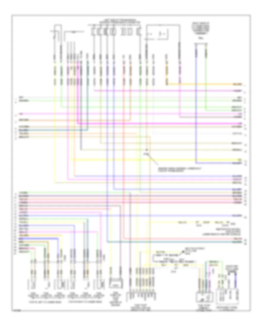 https://portal-diagnostov.com/license.html
Automotive Electricians Portal FZCO
Automotive Electricians Portal FZCO
https://portal-diagnostov.com/license.html
https://portal-diagnostov.com/license.html
Automotive Electricians Portal FZCO
Automotive Electricians Portal FZCOList of elements for 3.5L Turbo, Engine Performance Wiring Diagram (5 of 7) for Ford Flex SEL 2014:
- (bottom of right "c" pillar) g300
- (engine wiring harness, in breakout c168 on transmission)
- (left side of transmission) 6f50/6f55 transmission connector
- (right rear of cylinder head) cylinder head temperature sensor
- (top of left cylinder head)
- (top of right cylinder head)
- C1045
- C1046
- C212
- C310a
- C315
- Ce515
- Ce608
- Cet05
- Cet06
- Cet07
- Cet08
- Cet09
- Cet10
- Cet19
- Cet25
- Computer data lines system
- Cr167
- Ens
- Fpc
- Fpm
- Fppwr
- Fprtn
- Fuel injection pump (top center of engine)
- Fuel injector
- Fuel lvl 1
- Fuel pump assembly (in fuel tank)
- Fuel pump control module (right "c" pillar)
- Fuel vpwr
- Gd348
- Gnd
- Hs can +
- Hs can -
- Instrument panel cluster (ipc)
- Le111
- Lpc
- Nca
- Oss
- Re405
- Re515
- Restraints control module (rcm) (under rear of center console)
- Ret04
- Ret24
- Ret33
- Rtn
- S100
- S302
- S311
- S405
- Ssa
- Ssb
- Ssc
- Ssd
- Sse
- Tcc
- Tft
- Tft sig rtn
- Tr gnd
- Tr-1
- Tr-2
- Tr-3
- Tr-4
- Trs
- Tspc
- Tss
- Tss/oss gnd
- Tss/oss vpwr
- Ve225
- Ve518
- Vet27
- Vet29
- Vet30
- Vet31
- Vet32
3.5L Turbo, Engine Performance Wiring Diagram (6 of 7) for Ford Flex SEL 2014
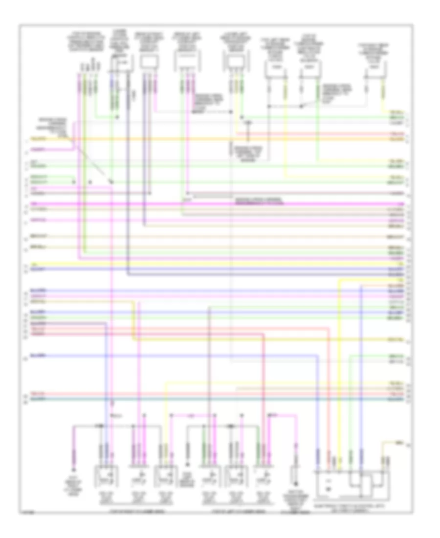 https://portal-diagnostov.com/license.html
Automotive Electricians Portal FZCO
Automotive Electricians Portal FZCO
https://portal-diagnostov.com/license.html
https://portal-diagnostov.com/license.html
Automotive Electricians Portal FZCO
Automotive Electricians Portal FZCOList of elements for 3.5L Turbo, Engine Performance Wiring Diagram (6 of 7) for Ford Flex SEL 2014:
- (engine wiring harness, near breakout to c1045)
- (engine wiring harness, near breakout to c1045) s105
- (engine wiring harness, near breakout to c1045) s126
- (engine wiring harness, near breakout to c1045) s161
- (engine wiring harness, top left side of engine)
- (lower left rear of engine) crankshaft position sensor
- (rear of left cylinder head) camshaft position sensor 21
- (rear of right cylinder head) camshaft position sensor 11
- (top left rear of engine) turbocharger bypass (tcby2) valve 2
- (top of engine) manifold absolute pressure/intake air temperature 2 (map/iat2) sensor
- (top of engine) turbocharger wastegate regulating valve solenoid
- (top of left cylinder head)
- (top of right cylinder head)
- (top right rear of engine) turbocharger bypass valve
- (under intake manifold) fuel rail pressure (frp) sensor
- C1046
- C1609a
- C1609b
- Coil on plug (cop) 1
- Coil on plug (cop) 2
- Coil on plug (cop) 3
- Coil on plug (cop) 4
- Coil on plug (cop) 5
- Coil on plug (cop) 6
- Electronic throttle control (etc) (on throttle body)
- G107 (rear of right cylinder head)
- G108 (left rear of engine)
- Iat2
- Ignition transformer capacitor 1 (rear of right cylinder head)
- Map
- S102
- S103
- S107
- S124
- S131
- S160
- Sigrtn
- Vref
3.5L Turbo, Engine Performance Wiring Diagram (7 of 7) for Ford Flex SEL 2014
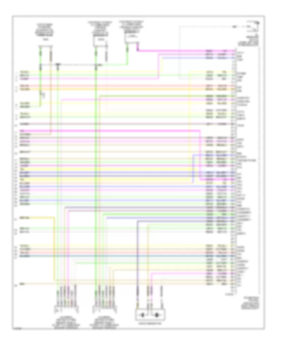 https://portal-diagnostov.com/license.html
Automotive Electricians Portal FZCO
Automotive Electricians Portal FZCO
https://portal-diagnostov.com/license.html
https://portal-diagnostov.com/license.html
Automotive Electricians Portal FZCO
Automotive Electricians Portal FZCOList of elements for 3.5L Turbo, Engine Performance Wiring Diagram (7 of 7) for Ford Flex SEL 2014:
- (top front of right cylinder head) variable camshaft timing (vct11) solenoid 11
- (top front of right cylinder head) variable camshaft timing (vct12) solenoid 12
- (top of rear of engine) evaporative emission (evap) purge valve
- C134
- C1381e
- Ce235
- Ce236
- Ce303
- Ce304
- Ce306
- Ce307
- Ce421
- Ce422
- Ce435
- Cet05
- Cet06
- Cet08
- Cet09
- Cet10
- Cet19
- Cht
- Ckp
- Cmc24
- Cmp11
- Cmp21
- Cop 1a
- Cop2c
- Cop4b
- Cop5d
- Etcref
- Etcrtn
- Frp
- Iat2
- Knock sensor (ks)
- Ks1 +
- Ks1 -
- Ks2 +
- Ks2 -
- Le111
- Le134
- Le423
- Le448
- Le449
- Le450
- Le451
- Le452
- Le453
- Lpc
- Map
- Oil pressure switch (lower left side of engine block)
- Ops
- Oss
- Powertrain control module (pcm) (right rear of engine compt)
- Re134
- Re323
- Re324
- Re405
- Re406
- Red
- Ret04
- Ret24
- Ret33
- S146
- Sigrtn
- Ssa
- Ssb
- Ssd
- Sse
- Tan
- Tcby
- Tcby2
- Tcc
- Tcwrvs
- Tft
- Tp 1
- Tp2
- Tr-1
- Tr-2
- Tr-3
- Tr-4
- Tss
- Tss/oss/tr gnd
- Universal heated oxygen sensor (ho2s) 11 (in right cylinder bank exhaust manifold)
- Universal heated oxygen sensor (ho2s) 21 (in left cylinder bank exhaust manifold)
- Uo2s11
- Uo2s21
- Uo2sgref11
- Uo2sgref21
- Uo2shtr11
- Uo2shtr21
- Uo2spc11
- Uo2spc21
- Uo2spct11
- Uo2spct21
- Vct11
- Vct12
- Ve706
- Ve707
- Ve711
- Ve712
- Ve727
- Ve740
- Ve801
- Ve802
- Ve804
- Ve818
- Ve819
- Ve824
- Ve826
- Ve827
- Vet27
- Vet29
- Vet30
- Vet31
- Vet32
- Vpwr
- Vref
EXTERIOR LIGHTS
Backup Lamps Wiring Diagram for Ford Flex SEL 2014
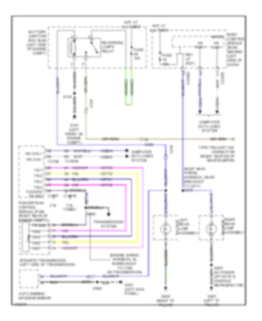 https://portal-diagnostov.com/license.html
Automotive Electricians Portal FZCO
Automotive Electricians Portal FZCO
https://portal-diagnostov.com/license.html
https://portal-diagnostov.com/license.html
Automotive Electricians Portal FZCO
Automotive Electricians Portal FZCOList of elements for Backup Lamps Wiring Diagram for Ford Flex SEL 2014:
- (body main wiring harness, near breakout to c211) s215
- (engine wiring harness, in in breakout to c168 on transmission)
- (w/ power liftgate & console refrigerator)
- 3.5l
- 3.5l turbo
- 6f50/6f55 transmission (left side of transmission)
- 7-pin trailer tow connector (right center of rear bumper)
- Auto dimming interior mirror
- Backup
- Battery junction box (bjb) (left side of engine compt)
- Body control module (bcm) (behind left side of dash)
- C1381b
- C1381e
- C175b
- C175t
- C219
- C2280d
- C2280f
- C260
- C405
- Computer data lines system
- Fuse 10a
- Fuse 15a
- G101 (left front of engine compt)
- G301 (left kick panel)
- G400 (right "d" pillar)
- G401 (left "d" pillar)
- Hot at all times
- Hs can +
- Hs can -
- Left rear lamp assembly
- Micro
- Powertrain control module (pcm) (right rear of engine compt)
- Rev lp (fet)
- Reversing lamps relay
- Right rear lamp assembly
- S100
- S143
- S904
- Tr gnd
- Tr-1
- Tr-2
- Tr-3
- Tr-4
- Tr-4 tss/oss tr gnd
- Transmissions system
- Trs
- Vdb04
- Vdb05
- Vet29
- Vet30
- Vet31
- Vet32
Exterior Lamps Wiring Diagram (1 of 2) for Ford Flex SEL 2014
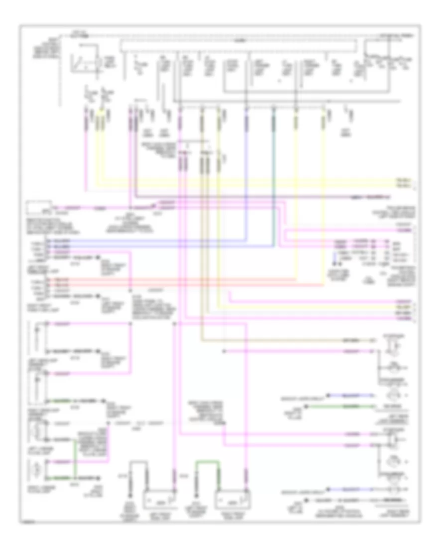 https://portal-diagnostov.com/license.html
Automotive Electricians Portal FZCO
Automotive Electricians Portal FZCO
https://portal-diagnostov.com/license.html
https://portal-diagnostov.com/license.html
Automotive Electricians Portal FZCO
Automotive Electricians Portal FZCOList of elements for Exterior Lamps Wiring Diagram (1 of 2) for Ford Flex SEL 2014:
- (body main wiring harness, near breakout to restraints control module) s306
- (not used)
- 3.5l
- 3.5l turbo
- Backup lamps circuit
- Body control module (bcm) (behind left side of dash)
- Bpp
- Bps
- C1381b
- C175b
- C210
- C2153c
- C2280b
- C2280c
- C2280d
- C2280e
- C2280f
- C405
- C431
- Cbp31
- Ccb08
- Ces09
- Computer data lines system
- Fuse 10a
- Fuse 15a
- Fuse 5a
- G100 (right front of engine compt)
- G101 (left front of engine compt)
- G400 (right "d" pillar)
- G401 (left "d" pillar)
- Gnd
- Hot at all times
- Hs can +
- Hs can -
- Leds
- Left corner lamp (fet)
- Left front park/turn lamp
- Left front side lamp
- Left headlamp assembly (w/ hid)
- Left license plate lamp
- Left rear lamp assembly
- Lf turn lamp (fet)
- Lr stop/ turn lamp (fet)
- Lr turn lamp (fet)
- Micro
- Park
- Park lamp relay
- Powertrain control module (pcm) (right rear of engine compt)
- Remote function actuator (rfa) module (w/ intelligent access) (behind right side of dash)
- Reverse
- Rf turn lamp (fet)
- Right corner lamp (fet)
- Right front park/turn lamp
- Right front side lamp
- Right headlamp assembly (w/ hid)
- Right license plate lamp
- Right rear lamp assembly
- Rr stop/ turn lamp (fet)
- Rr turn lamp (fet)
- S119
- S139 (dash panel to headlamp junction wiring harness, near breakout to engine cooling fan motor)
- S140
- S204 (w/ intelligent access) (main wiring harness, near breakout to c210)
- S213
- S214
- S409 (backup alarm jumper wiring harness, near breakout to right license plate lamp)
- S418
- S420 (w/ power liftgate & refrigerated console)
- Side marker
- Stop/ chmsl (fet)
- Stop/turn
- Tail
- Trailer brake control (tbc) module (left side of dash)
- Turn 1
- Turn 2
- Vdb04
- Vdb05
Exterior Lamps Wiring Diagram (2 of 2) for Ford Flex SEL 2014
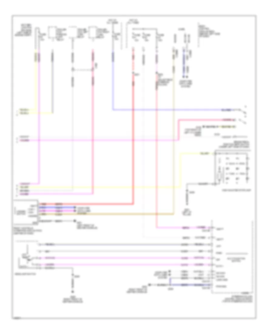 https://portal-diagnostov.com/license.html
Automotive Electricians Portal FZCO
Automotive Electricians Portal FZCO
https://portal-diagnostov.com/license.html
https://portal-diagnostov.com/license.html
Automotive Electricians Portal FZCO
Automotive Electricians Portal FZCOList of elements for Exterior Lamps Wiring Diagram (2 of 2) for Ford Flex SEL 2014:
- Auto 1
- Battery junction box (bjb) (left side of engine compt)
- Body control module (bcm) (behind left side of dash)
- Brake pedal position (bpp) switch (under left side of dash)
- C2280b
- C2280f
- C2414a
- C2414b
- C260
- Clf19
- Clf23
- Clf24
- Cls32
- Cls34
- Column)
- Computer data lines system
- Front controls interface module (fcim) (center of dash)
- Fuse 10a
- Fuse 15a
- G106 (top front of left cylinder head)
- G200 (right front of center console)
- G201 (left front of center console)
- G401 (left "d" pillar)
- Gd374
- Gd375
- Gnd
- Hazard
- Hazard switch
- Headlamp switch
- High mounted stoplamp
- Hot at all times
- Hs can +
- Hs can -
- Hs can+
- Hs can-
- I can +
- I can -
- Logic gnd
- Low
- Micro
- Multi-function switch
- Off
- Park
- Pwr gnd
- Red
- S130
- S201
- S205
- S206
- S406
- Sbp09
- Sbp23
- Sbp24
- Steering column control module (sccm) (top of steering column)
- Trailer tow left turn relay
- Trailer tow parking lamp relay
- Trailer tow right turn relay
- Vbatt
- Vdb04
- Vdb05
- Vdb13
- Vdb14
Trailer Tow Wiring Diagram for Ford Flex SEL 2014
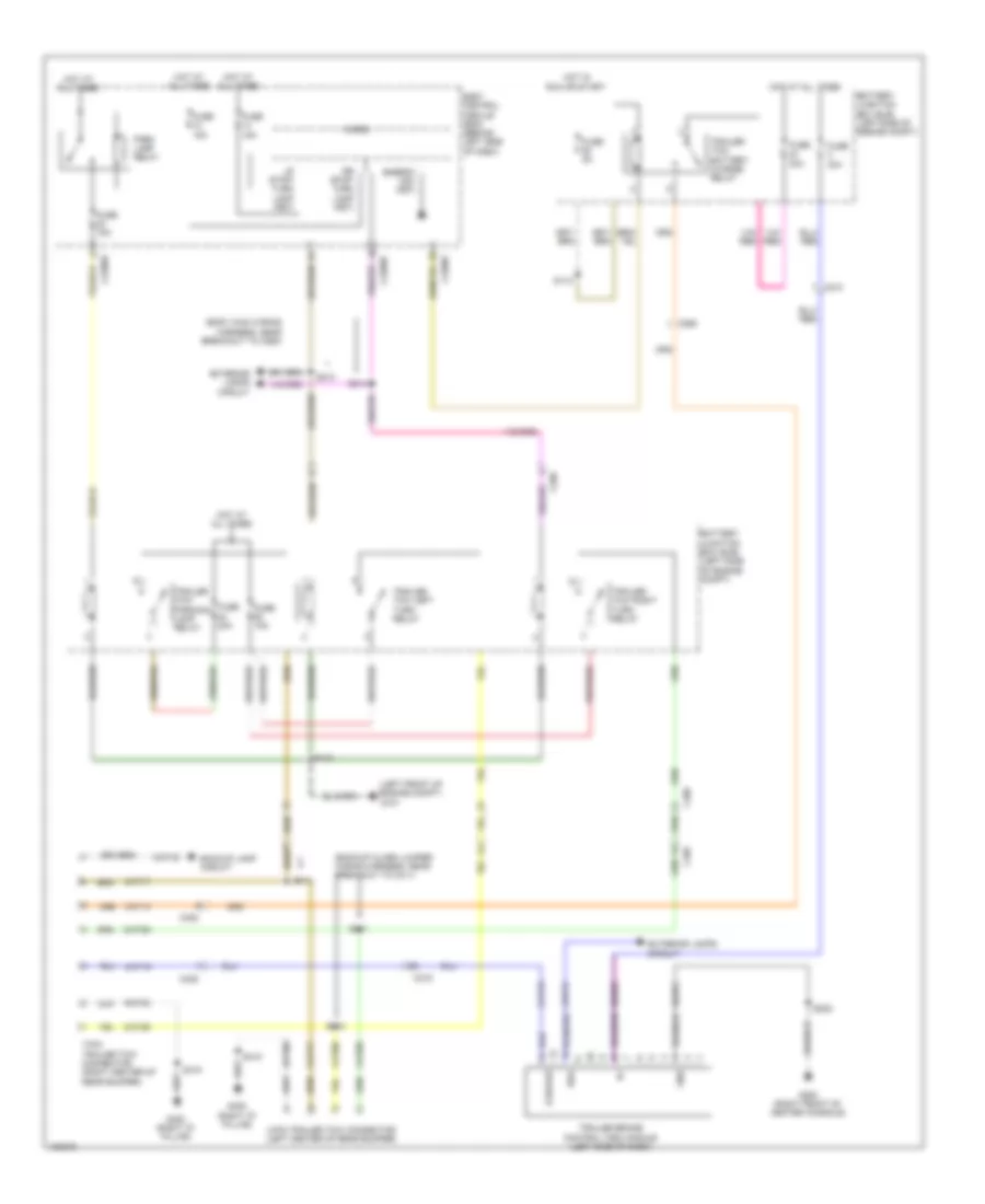 https://portal-diagnostov.com/license.html
Automotive Electricians Portal FZCO
Automotive Electricians Portal FZCO
https://portal-diagnostov.com/license.html
https://portal-diagnostov.com/license.html
Automotive Electricians Portal FZCO
Automotive Electricians Portal FZCOList of elements for Trailer Tow Wiring Diagram for Ford Flex SEL 2014:
- (backup alarm jumper wiring harness, near breakout to c411)
- (body main wiring harness, near breakout to c260)
- (left front of engine compt) g101
- 4-pin trailer tow connector (left center of rear bumper)
- 7-pin trailer tow connector (right center of rear bumper)
- Backup lamp circuit
- Battery junction box (bjb) (left side of engine compt)
- Body control module (bcm) (behind left side of dash)
- Boo
- C210
- C215
- C2280d
- C2280e
- C2280f
- C260
- C405
- Cat06
- Cat09
- Cat14
- Cat16
- Cat17
- Cat19
- Cato6
- Cato9
- Cbp31
- E-brake
- Energy mgt (fet)
- Exterior lamps circuit
- Fuse 15a
- Fuse 20a
- Fuse 30a
- Fuse 5a
- G200 (right front of center console)
- G400 (right "d" pillar)
- Gd375
- Gnd
- Hot at all times
- Hot in run or start
- Lr stop/ turn lamp (fet)
- Micro
- Park lamp relay
- Rat08
- Rr stop/ turn lamp (fet)
- S112
- S143
- S205
- S213
- S214
- S411
- S413
- S414
- S418
- Sbb03
- Trailer brake control (tbc) module (left side of dash)
- Trailer tow battery charge relay
- Trailer tow left turn relay
- Trailer tow parking lamp relay
- Trailer tow right turn relay
GROUND DISTRIBUTION
Ground Distribution Wiring Diagram (1 of 5) for Ford Flex SEL 2014
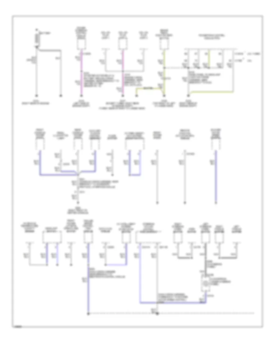 https://portal-diagnostov.com/license.html
Automotive Electricians Portal FZCO
Automotive Electricians Portal FZCO
https://portal-diagnostov.com/license.html
https://portal-diagnostov.com/license.html
Automotive Electricians Portal FZCO
Automotive Electricians Portal FZCOList of elements for Ground Distribution Wiring Diagram (1 of 5) for Ford Flex SEL 2014:
- (engine wiring harness, near breakout to coil on plug 2)
- (main wiring harness, in breakout to blower motor speed control) s206
- (w/ intelligent access) start/stop switch
- (w/ park assist) active park assist switch
- 3.5l
- 3.5l turbo
- Auxiliary climate control assembly
- Battery
- Blower motor speed control
- Brake pedal position (bpp) switch
- C134
- C1381b
- C1467b
- C175b
- C214
- C2153d
- C217b
- C218a
- C218b
- C228c
- C2414a
- C2414b
- C3376
- Clockspring (under steering wheel)
- Coil on plug (cop) 1
- Coil on plug (cop) 2
- Coil on plug (cop) 3
- Datc hvac module
- Floor shifter
- Front console power point
- Front power liftgate open/close switch
- Front power point
- G102 (right rear of engine compt)
- G103 (left side of engine compt)
- G104 (right rear of engine)
- G106 (top front of left cylinder head)
- G107 (except turbo: right rear of engine compt) (turbo: rear of right cylinder head)
- G200 (right front of center console)
- Headlamp switch
- Horn switch
- In-vehicle temperature/ humidity sensor
- Left paddle shifter
- Left steering wheel switch
- Nca
- Power steering control module (pscm)
- Powertrain control module (pcm)
- Prndl illumination lamp
- Rear console power point
- Remote function actuator (rfa) module
- Right paddle shifter
- Right steering wheel switch
- S103
- S104 (starter motor relay & battery ground wiring harness, near breakout to heated oxygen sensor no. 12)
- S299 (in steering wheel)
- Steering column control module (sccm)
- Trailer brake control (tbc) module
Ground Distribution Wiring Diagram (2 of 5) for Ford Flex SEL 2014
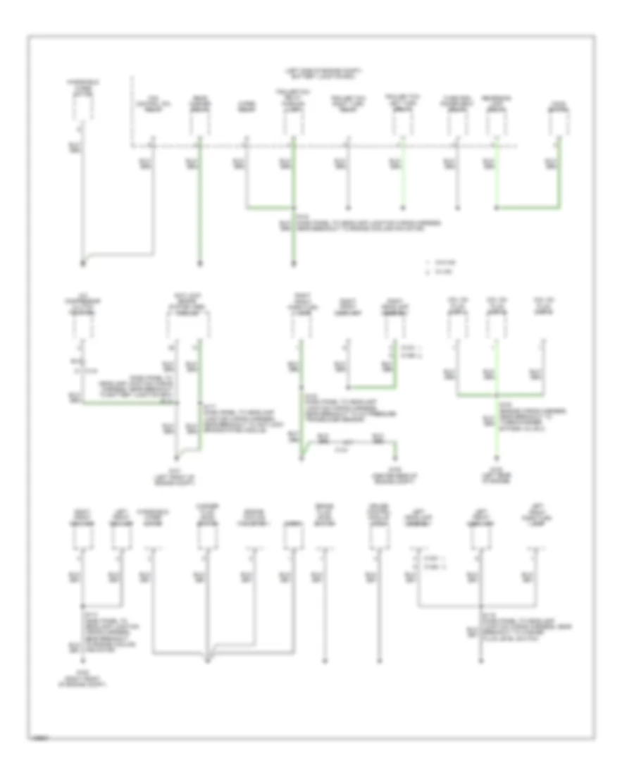 https://portal-diagnostov.com/license.html
Automotive Electricians Portal FZCO
Automotive Electricians Portal FZCO
https://portal-diagnostov.com/license.html
https://portal-diagnostov.com/license.html
Automotive Electricians Portal FZCO
Automotive Electricians Portal FZCOList of elements for Ground Distribution Wiring Diagram (2 of 5) for Ford Flex SEL 2014:
- (dash panel to headlamp junction wiring harness, near breakout to battery junction box) s114
- (left side of engine compt) battery junction box
- A/c compressor clutch field coil
- Anti-lock brake system (abs) module
- Brake fluid level switch
- Brake system module)
- C1021
- C1041
- C1284
- C1285
- C144
- Coil on plug (cop) 4
- Coil on plug (cop) 5
- Coil on plug (cop) 6
- Cruise control module (ccm)
- Engine cooling fan motor 1
- Fan control (fc) relay
- Fan motor)
- G100 (right front of engine compt)
- G101 (left front of engine compt)
- G108 (left rear of engine)
- G109 (center rear of engine compt)
- Hood switch
- Horn
- Left front fog lamp
- Left front park/turn lamp
- Left front side lamp
- Left headlamp assembly
- Near breakout to engine cooling fan motor)
- Rear washer relay
- Reversing lamp relay
- Right front fog lamp
- Right front park/turn lamp
- Right front side lamp
- Right headlamp assembly
- S140 (dash panel to headlamp junction wiring harness, near breakout to a/c pressure transducer sensor)
- Third row power seat relay
- Trailer tow left turn relay
- Trailer tow relay parking lamp
- Trailer tow right turn relay
- Turbocharger bypass valve 2)
- W/ hid
- W/o hid
- Washer fluid level switch
- Windshield wiper motor
- Wiper relay
Ground Distribution Wiring Diagram (3 of 5) for Ford Flex SEL 2014
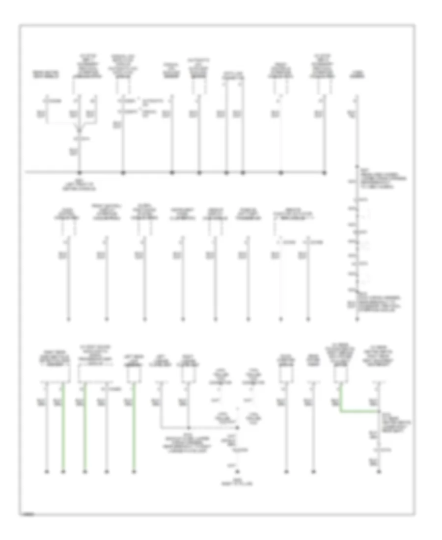 https://portal-diagnostov.com/license.html
Automotive Electricians Portal FZCO
Automotive Electricians Portal FZCO
https://portal-diagnostov.com/license.html
https://portal-diagnostov.com/license.html
Automotive Electricians Portal FZCO
Automotive Electricians Portal FZCOList of elements for Ground Distribution Wiring Diagram (3 of 5) for Ford Flex SEL 2014:
- (automatic a/c) autolamp/ sunload sensor
- (manual a/c) emtc hvac module (automatic a/c) datc hvac module
- (manual a/c) sunload sensor
- (under right rear seat)
- (w/ rear folding seats) right second row power fold seat motor
- (w/ rear heated seats)
- (w/ sony sound) audio digital signal processing (dsp) module
- (w/ sync gen 1)
- (w/ sync gen 2)
- 4-pin trailer tow
- 4-pin trailer tow connector
- 7-pin trailer tow
- 7-pin trailer tow connector
- Accessory protocol interface module (apim)
- Accessory protocol interface module)
- Audio control module (acm)
- Automatic a/c
- C212
- C214
- C2153c
- C2153e
- C228a
- C2357a
- C3134
- C3304b
- C405
- C410
- C431
- C4326c
- Data link connector
- Dc/ac inverter module
- Front control/ display interface module (fcdim)
- Front controls interface module (fcim)
- G201 (left front of center console)
- G400 (right "d" pillar)
- Global positioning system module (gpsm)
- Headup display (hud) module
- Instrument panel cluster (ipc)
- Left license plate lamp
- Left rear lamp assembly
- Manual a/c
- Nca
- Passive anti-theft transceiver
- Rear heated seat module
- Rear power point
- Remote function actuator (rfa) module
- Right license plate lamp
- Right rear seat backrest heater mat
- Right rear side obstacle detection (sod) sensor
- S315 (w/ rear heated seats)
- S407 (rear video camera jumper wiring harness, near breakout to video camera)
- S418 (backup alarm jumper wiring harness, near breakout to right license plate lamp)
- Video camera
Ground Distribution Wiring Diagram (4 of 5) for Ford Flex SEL 2014
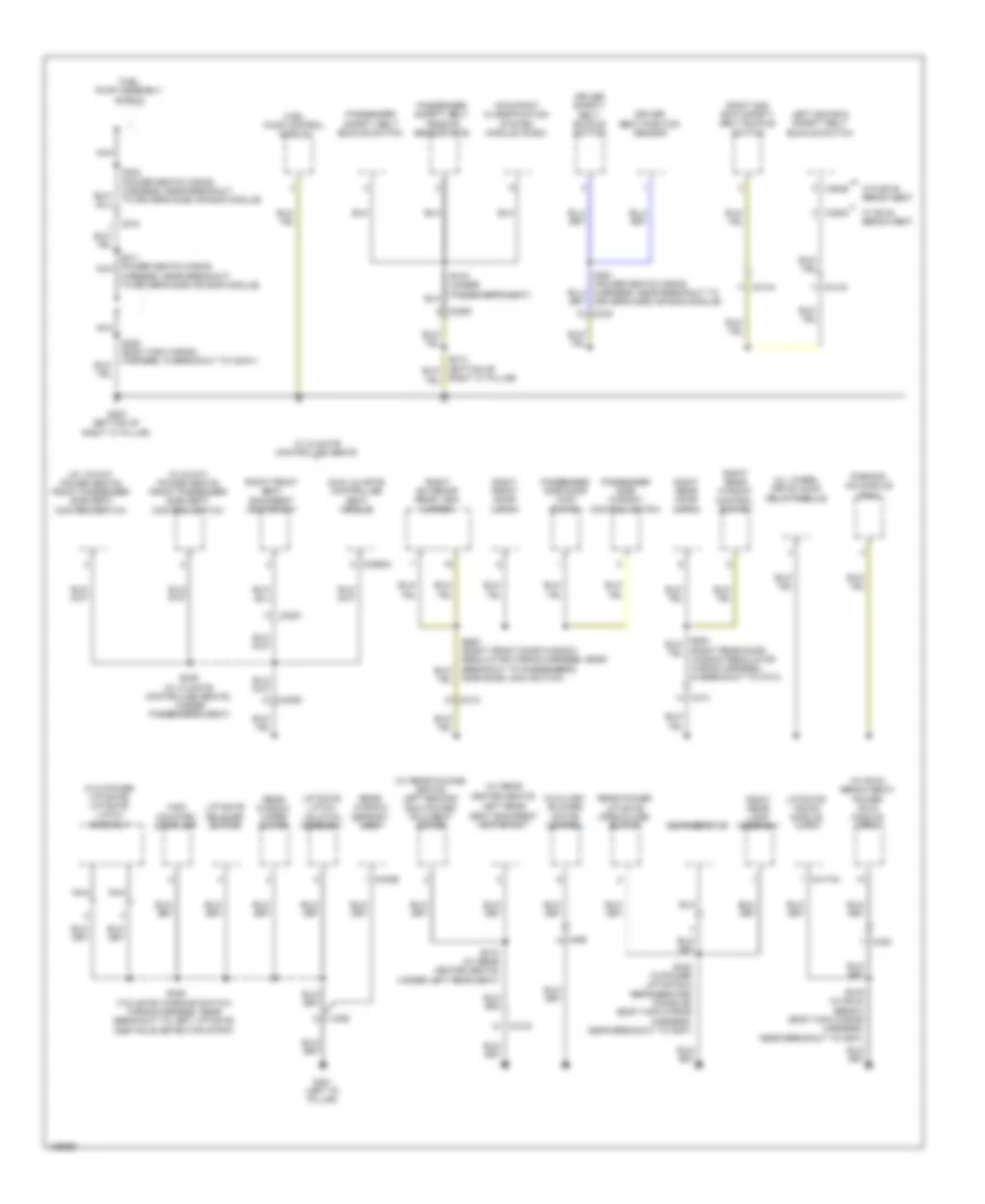 https://portal-diagnostov.com/license.html
Automotive Electricians Portal FZCO
Automotive Electricians Portal FZCO
https://portal-diagnostov.com/license.html
https://portal-diagnostov.com/license.html
Automotive Electricians Portal FZCO
Automotive Electricians Portal FZCOList of elements for Ground Distribution Wiring Diagram (4 of 5) for Ford Flex SEL 2014:
- (w/ 10-way power seats) front passenger side seat control switch
- (w/ 6-way power seats) front passenger side seat control switch
- (w/ 60/40 bench seat) power fold module (pfm)
- (w/ rear folding seats) left second row power fold seat motor
- (w/ rear heated seats)
- (w/o power liftgate) liftgate latch assembly
- All wheel drive (awd) relay module
- Auxiliary blower motor control
- C3050
- C3051
- C312
- C3133
- C3134
- C314
- C315 j
- C3265a m
- C340
- C3646
- C3802
- C402b
- C406
- C408
- C4174a
- C465
- Driver safety belt buckle switch
- Driver seat position sensor
- Dual climate controlled seat module
- Fuel pump assembly shield
- Fuel pump control module
- G300 (bottom of right "c" pillar)
- G401 (left "d" pillar)
- Harness, near breakout to driver's side air bag module)
- High mounted stoplamp
- Left 2nd row safety belt buckle switch
- Left rear seat backrest heater mat
- Liftgate latch/ unlatch assembly
- Liftgate release switch
- Liftgate/ trunk module (ltm)
- Nca
- Occupant classification system module (ocsm)
- Parking aid module (pam)
- Passenger safety belt buckle switch
- Passenger safety belt tension sensor (bts)
- Passenger side door lock switch
- Passenger side window control switch
- Rear power liftgate open/close switch
- Rear window defrost grid
- Rear window wiper motor
- Refrigerator
- Right "c" pillar)
- Right 2nd row safety belt buckle switch
- Right exterior rear view mirror
- Right front door latch
- Right front seat backrest heater mat
- Right rear door latch
- Right rear lamp assembly
- Right rear window control switch
- S302 (power seats wiring harness, near breakout to driver's side air bag module)
- S310 (w/ rear heated seats) (under left rear seat)
- S311 (power seats wiring nca
- S319 (under passenger's seat)
- S325 (w/ climate controlled seats) (under passenger's seat)
- S351 (power seats wiring harness, near breakout to driver's side air bag module)
- S405 (body main wiring harness, in breakout to c3041)
- S406 (tailgate warning switch wiring harness, near breakout to left liftgate obstacle detection strip)
- S419 (w/ 60/40 bench) (body main wiring harness, near breakout to g401)
- S420 (w/power liftgate & refrigerated console) (body main wiring harness, near breakout to g401)
- S600 (right front door window regulator wiring harness, near
- Side door lock switch)
- W/ 60/40 bench seat
- W/ climate controlled seats
- W/o 60/40 bench seat
- Window regulator wiring harness, in breakout to c314)
Ground Distribution Wiring Diagram (5 of 5) for Ford Flex SEL 2014
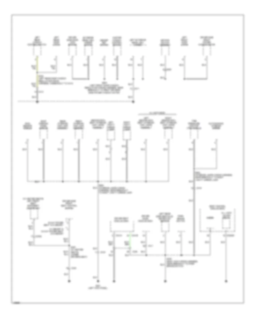 https://portal-diagnostov.com/license.html
Automotive Electricians Portal FZCO
Automotive Electricians Portal FZCO
https://portal-diagnostov.com/license.html
https://portal-diagnostov.com/license.html
Automotive Electricians Portal FZCO
Automotive Electricians Portal FZCOList of elements for Ground Distribution Wiring Diagram (5 of 5) for Ford Flex SEL 2014:
- (w/ heated seats) left front seat backrest heater mat
- 6-way power seat w/o memory
- All lock/ unlock relay
- Auto-dimming interior mirror
- Body control module (bcm)
- C219
- C2280d
- C3052
- C311
- C313
- C339
- C340
- C341a
- C341b
- C500
- Driver door module (ddm)
- Driver seat module (dsm)
- Driver side door lock switch
- Driver side front power window motor
- Driver side front seat control switch
- Exterior rear view mirror switch
- Front interior/ map lamp assembly
- G301 (left kick panel)
- Keypad switch assembly
- Left exterior rear view mirror
- Left front door latch
- Left rear door latch
- Left rear side obstacle detection sensor
- Left rear window control switch
- Left second row seat interior/ map lamps assembly
- Left vanity mirror lamp
- Master window control switch
- Memory set switch
- Micro
- Park brake switch
- Rain sensor module
- Rear interior/ map lamp assembly
- Right second row seat interior/ map lamps assembly
- Right vanity mirror lamp
- Roof opening panel module
- S305 (body main wiring harness, near breakout to park brake switch)
- S357 (w/ heated seats) (under driver's seat)
- S500 (left front door window regulator wiring harness, near breakout to front driver's side power window motor)
- S900 (interior lamps wiring harness, near breakout to right vanity mirror lamp)
- S904 (interior lamps wiring harness, near breakout to right vanity mirror lamp)
- Second row seat interior/ map lamps assembly
- Tire pressure monitor (tpm) module
- W/ memory & 10-way power seat w/o memory
- W/ vista roof
HEADLIGHTS
Headlights Wiring Diagram, with High Intensity Gas Discharge Headlights (1 of 2) for Ford Flex SEL 2014
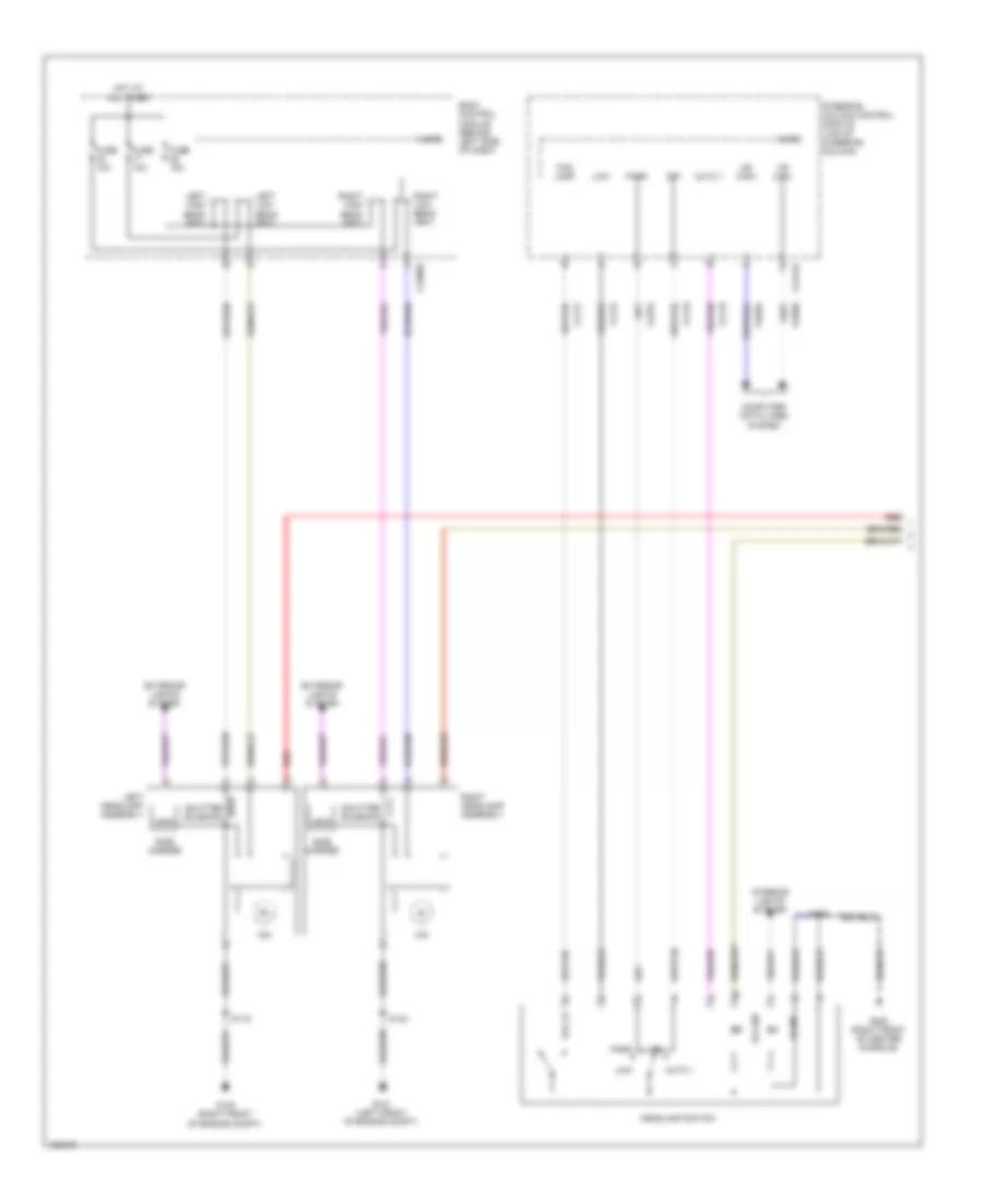 https://portal-diagnostov.com/license.html
Automotive Electricians Portal FZCO
Automotive Electricians Portal FZCO
https://portal-diagnostov.com/license.html
https://portal-diagnostov.com/license.html
Automotive Electricians Portal FZCO
Automotive Electricians Portal FZCOList of elements for Headlights Wiring Diagram, with High Intensity Gas Discharge Headlights (1 of 2) for Ford Flex SEL 2014:
- Auto 1
- Body control module (behind left side of dash)
- C2280e
- C2414a
- Clf19
- Clf21
- Clf23
- Clf24
- Cls34
- Computer data lines system
- Exterior lights system
- Fog ind
- Fog lamp
- Fog lp
- Fuse 10a
- Fuse 15a
- G100 (right front of engine compt)
- G101 (left front of engine compt)
- G200 (right front of center console)
- Headlamp switch
- Hid
- Hot at all times
- Hs can+
- Hs can-
- Illum
- Interior lights system
- Leds
- Left headlamp assembly
- Left high beam (fet)
- Left low beam (fet)
- Low
- Micro
- Off
- Park
- Red
- Right headlamp assembly
- Right high beam (fet)
- Right low beam (fet)
- S119
- S140
- S205
- Shutter solenoid
- Side marker
- Steering column control module (top of steering column)
- Vdb04
- Vdb05
Headlights Wiring Diagram, with High Intensity Gas Discharge Headlights (2 of 2) for Ford Flex SEL 2014
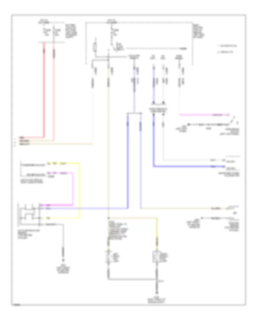 https://portal-diagnostov.com/license.html
Automotive Electricians Portal FZCO
Automotive Electricians Portal FZCO
https://portal-diagnostov.com/license.html
https://portal-diagnostov.com/license.html
Automotive Electricians Portal FZCO
Automotive Electricians Portal FZCOList of elements for Headlights Wiring Diagram, with High Intensity Gas Discharge Headlights (2 of 2) for Ford Flex SEL 2014:
- Autolamp sens in
- Autolamp/sunload sensor (top center of dash)
- Automatic a/c
- Battery junction box (bjb) (left side of engine compt)
- Body control module (behind left side of dash)
- C2280a
- C2280b
- C2280c
- C2280e
- C2280f
- C228b
- Cmc25
- Computer data lines system
- Datc hvac module (right side of dash)
- Driver sunload
- Engine compt)
- Fog lamp relay
- Fuse 15a
- Fuse 20a
- G100 (right front of
- G201 (left front of center console)
- G301 (left kick panel)
- Hot at all times
- Hs can +
- Hs can-
- Instrument panel cluster (ipc)
- Left front fog lamp
- Manual a/c
- Micro
- Ms can+
- Ms can-
- Park brake
- Park brake switch (left kick panel)
- Passenger sunload
- Red
- Right front fog lamp
- S118
- S132 (dash panel to headlamp junction wiring harness, near breakout to engine cooling fan motor)
- S305
- Sunload sensor (top center of dash)
- Vdb04
- Vdb05
- Vh416
- Vh417
- Vlf14
Headlights Wiring Diagram, without High Intensity Gas Discharge Headlights (1 of 2) for Ford Flex SEL 2014
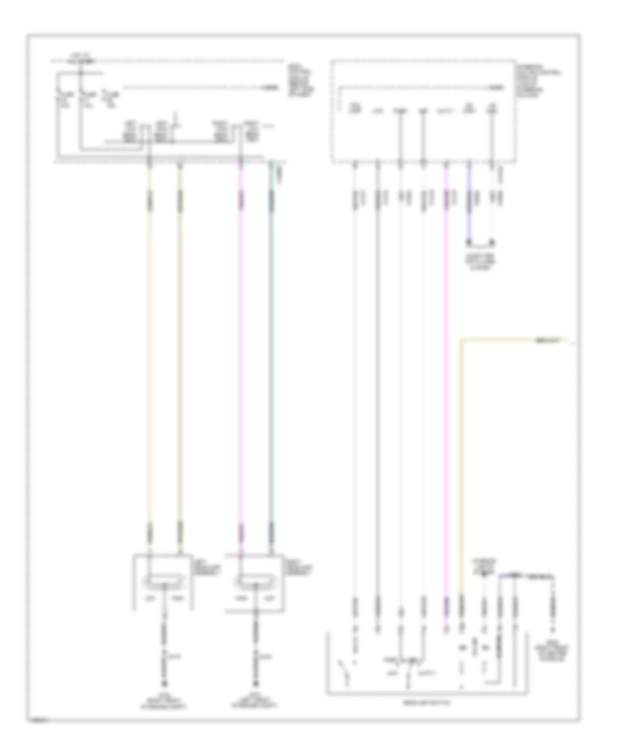 https://portal-diagnostov.com/license.html
Automotive Electricians Portal FZCO
Automotive Electricians Portal FZCO
https://portal-diagnostov.com/license.html
https://portal-diagnostov.com/license.html
Automotive Electricians Portal FZCO
Automotive Electricians Portal FZCOList of elements for Headlights Wiring Diagram, without High Intensity Gas Discharge Headlights (1 of 2) for Ford Flex SEL 2014:
- Auto 1
- Body control module (behind left side of dash)
- C2280e
- C2414a
- Clf19
- Clf21
- Clf23
- Clf24
- Cls34
- Computer data lines system
- Fog ind
- Fog lamp
- Fog lp
- Fuse 10a
- Fuse 15a
- G100 (right front of engine compt)
- G101 (left front of engine compt)
- G200 (right front of center console)
- Headlamp switch
- High
- Hot at all times
- Hs can+
- Hs can-
- Illum ind
- Interior lights system
- Left headlamp assembly
- Left high beam (fet)
- Left low beam (fet)
- Low
- Micro
- Off
- Park
- Right headlamp assembly
- Right high beam (fet)
- Right low beam (fet)
- S119
- S140
- S205
- Steering column control module (top of steering column)
- Vdb04
- Vdb05
Headlights Wiring Diagram, without High Intensity Gas Discharge Headlights (2 of 2) for Ford Flex SEL 2014
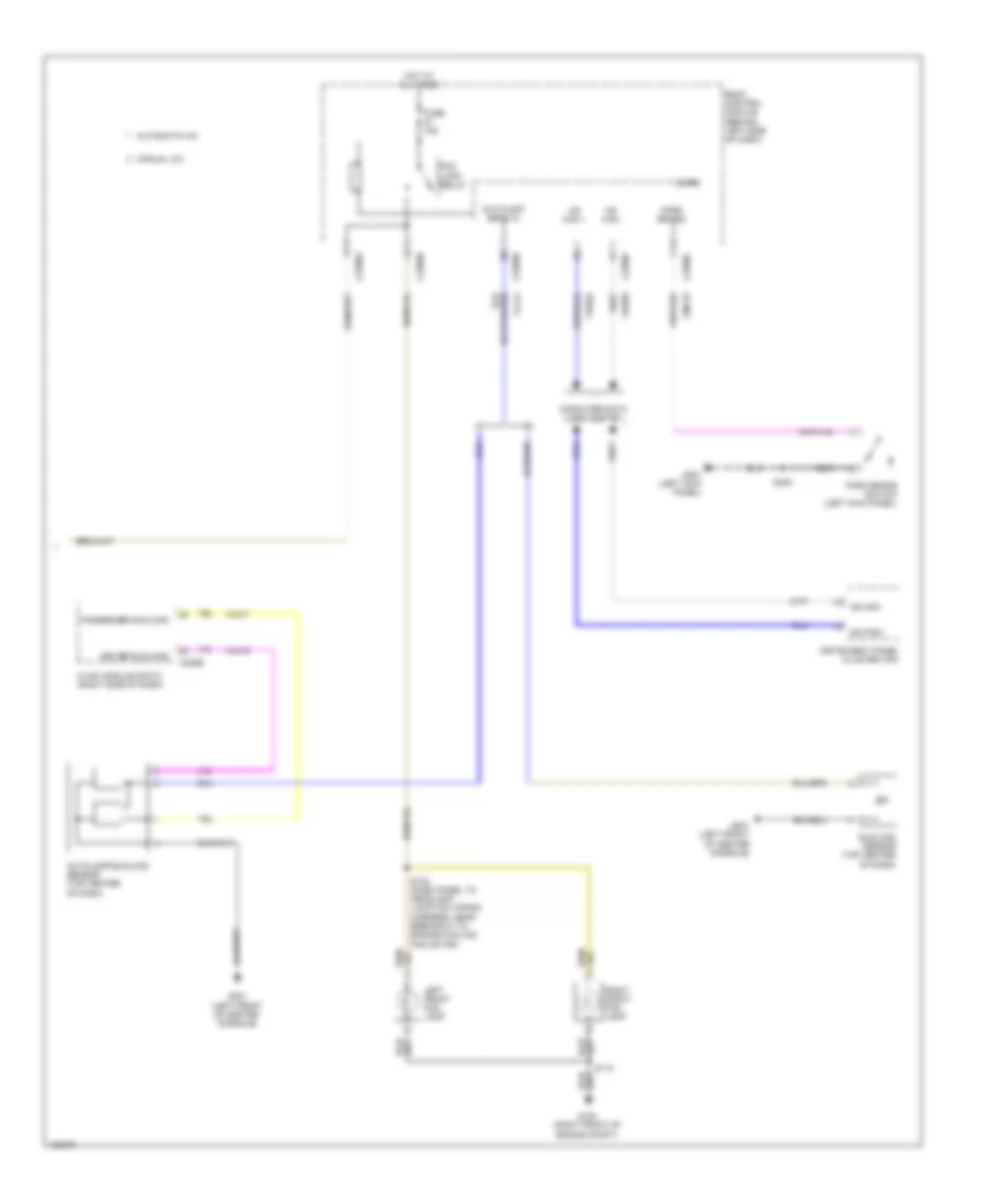 https://portal-diagnostov.com/license.html
Automotive Electricians Portal FZCO
Automotive Electricians Portal FZCO
https://portal-diagnostov.com/license.html
https://portal-diagnostov.com/license.html
Automotive Electricians Portal FZCO
Automotive Electricians Portal FZCOList of elements for Headlights Wiring Diagram, without High Intensity Gas Discharge Headlights (2 of 2) for Ford Flex SEL 2014:
- Autolamp sens in
- Autolamp/sunload sensor (top center of dash)
- Automatic a/c
- Body control module (behind left side of dash)
- C2280a
- C2280b
- C2280c
- C2280e
- C2280f
- C228b
- Cmc25
- Computer data lines system
- Driver sunload
- Engine compt)
- Fog lamp relay
- Fuse 15a
- G100 (right front of
- G201 (left front of center console)
- G301 (left kick panel)
- Hot at all times
- Hs can +
- Hs can-
- Hvac module (datc) (right side of dash)
- Instrument panel cluster (ipc)
- Left front fog lamp
- Manual a/c
- Micro
- Ms can+
- Ms can-
- Park brake
- Park brake switch (left kick panel)
- Passenger sunload
- Right front fog lamp
- S118
- S132 (dash panel to headlamp junction wiring harness, near breakout to engine cooling fan motor)
- S305
- Sunload sensor (top center of dash)
- Vdb04
- Vdb05
- Vh416
- Vh417
- Vlf14
HORN
Horn Wiring Diagram for Ford Flex SEL 2014
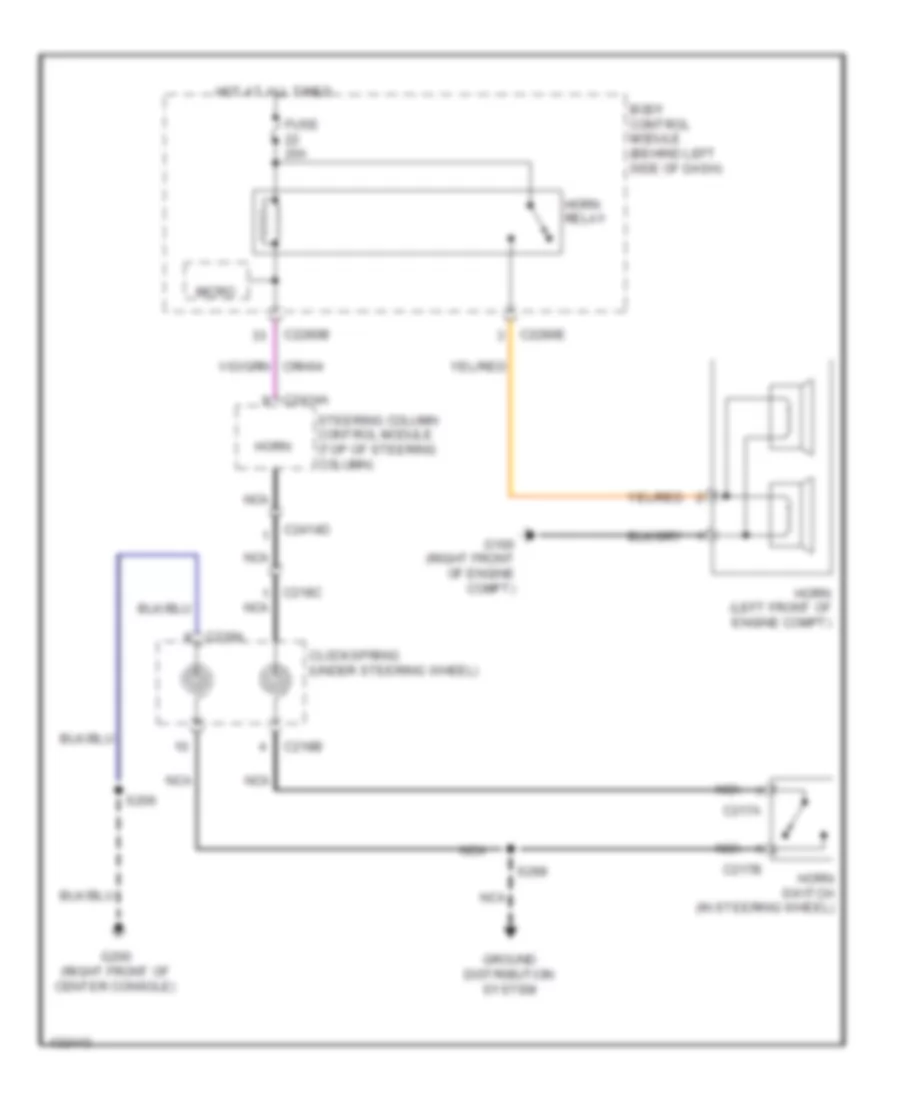 https://portal-diagnostov.com/license.html
Automotive Electricians Portal FZCO
Automotive Electricians Portal FZCO
https://portal-diagnostov.com/license.html
https://portal-diagnostov.com/license.html
Automotive Electricians Portal FZCO
Automotive Electricians Portal FZCOList of elements for Horn Wiring Diagram for Ford Flex SEL 2014:
- Body control module (behind left side of dash)
- C217a
- C217b
- C218a
- C218b
- C218c nca
- C2280b
- C2280e
- C2414a
- C2414d
- Clockspring (under steering wheel)
- Fuse 20a
- G100 (right front of engine compt)
- G200 (right front of center console)
- Ground distribution system
- Horn
- Horn (left front of engine compt)
- Horn relay
- Horn switch (in steering wheel)
- Hot at all times
- Micro
- Nca
- S206
- S299
- Steering column control module (top of steering column)
INSTRUMENT CLUSTER
Instrument Cluster Wiring Diagram for Ford Flex SEL 2014
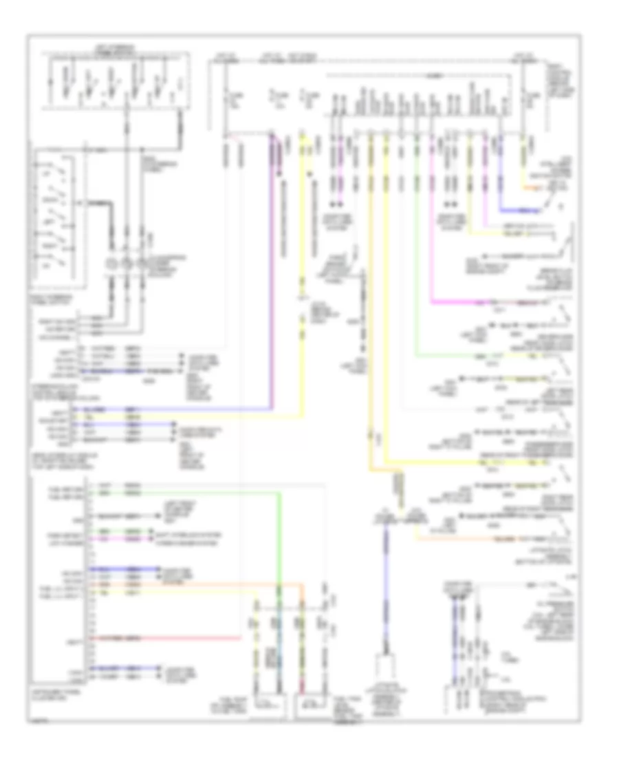 https://portal-diagnostov.com/license.html
Automotive Electricians Portal FZCO
Automotive Electricians Portal FZCO
https://portal-diagnostov.com/license.html
https://portal-diagnostov.com/license.html
Automotive Electricians Portal FZCO
Automotive Electricians Portal FZCOList of elements for Instrument Cluster Wiring Diagram for Ford Flex SEL 2014:
- (left front of center console) g201
- (w/o intelligent access) ignition switch
- 3.5l
- 4 way down
- 4 way left
- 4 way right
- 4 way up
- A/d channel 1
- A/d return
- Ajar lf door
- Body control module (behind left side of dash)
- Brake fluid level switch (on brake fluid reservoir)
- Brk fluid sw
- C1381b
- C1381e
- C175b
- C175e
- C212
- C218b
- C2280b
- C2280c
- C2280f
- C228oa
- C228ob
- C2414a
- C311
- C312
- C313
- C314
- C315
- C431
- Cbp35
- Cdc30
- Cet52
- Clockspring (under steering column)
- Cmc19
- Cmc20
- Cmc24
- Cmc25
- Computer data lines system
- Cpl26
- Cpl31
- Cpl36
- Cpl39
- Cpl44
- Down
- Driver's side front door latch (rear of driver's door)
- Eop sw
- Fuel lvl input 1
- Fuel lvl input 2
- Fuel pump (fp) assembly (in fuel tank)
- Fuel return
- Fuel tank level sensor (fuel tank assembly)
- Fuse 10a
- Fuse 15a
- Fuse 5a
- G100 (right front of engine compt)
- G200 (right front of center console)
- G201 (left front of center console)
- G300 (bottom of right "c" pillar)
- G301 (left kick panel)
- G401 (left "d" pillar)
- Gd374
- Gd375
- Gnd
- Head up display module (w/ adaptive cruise) (top left side of dash)
- Hot at all times
- Hot in run or start
- Hs can+
- Hs can-
- I can+
- I can-
- Instrument panel cluster (ipc)
- J/c 24 (behind center of dash)
- Key in
- Key in ignition
- Left
- Left rear door latch (rear of left rear door)
- Left steering wheel switch
- Liftgate ajar
- Liftgate latch assembly (bottom of liftgate)
- Liftgate latch/unlatch assembly (center of liftgate assembly)
- Logic gnd
- Low washer
- Lr door ajar
- Micro
- Ms can+
- Ms can-
- Nca
- Oil pressure switch (3.5l: left rear of engine block) (3.5l turbo: lower left side of engine block)
- Park brake sw
- Park brake switch (left kick panel)
- Park detect
- Passenger's side front door latch (rear of front passenger's door)
- Pnk
- Power distribution system
- Powertrain control module (pcm) (right rear of engine compt)
- Push button
- Rf door ajar
- Right
- Right rear door latch (rear of right rear door)
- Right steering wheel switch
- Right sw gnd
- Rmc19
- Rmc32
- Rmc33
- Rr door ajar
- Run/start
- S206
- S220 (in steering wheel)
- S305
- S406
- S500
- S600
- S700
- S800
- Sbp11
- Sbp23
- Shift interlock system
- Steering column control module (top of steering column)
- Sw rtn brake fluid
- Turbo
- Vbatt
- Vdb04
- Vdb05
- Vdb06
- Vdb07
- Vdb13
- Vdb14
- Vmc11
- Vmc23
- W/ power liftgate
- W/o power liftgate
- Wiper/washer system
INTERIOR LIGHTS
Courtesy Lamps Wiring Diagram (1 of 3) for Ford Flex SEL 2014
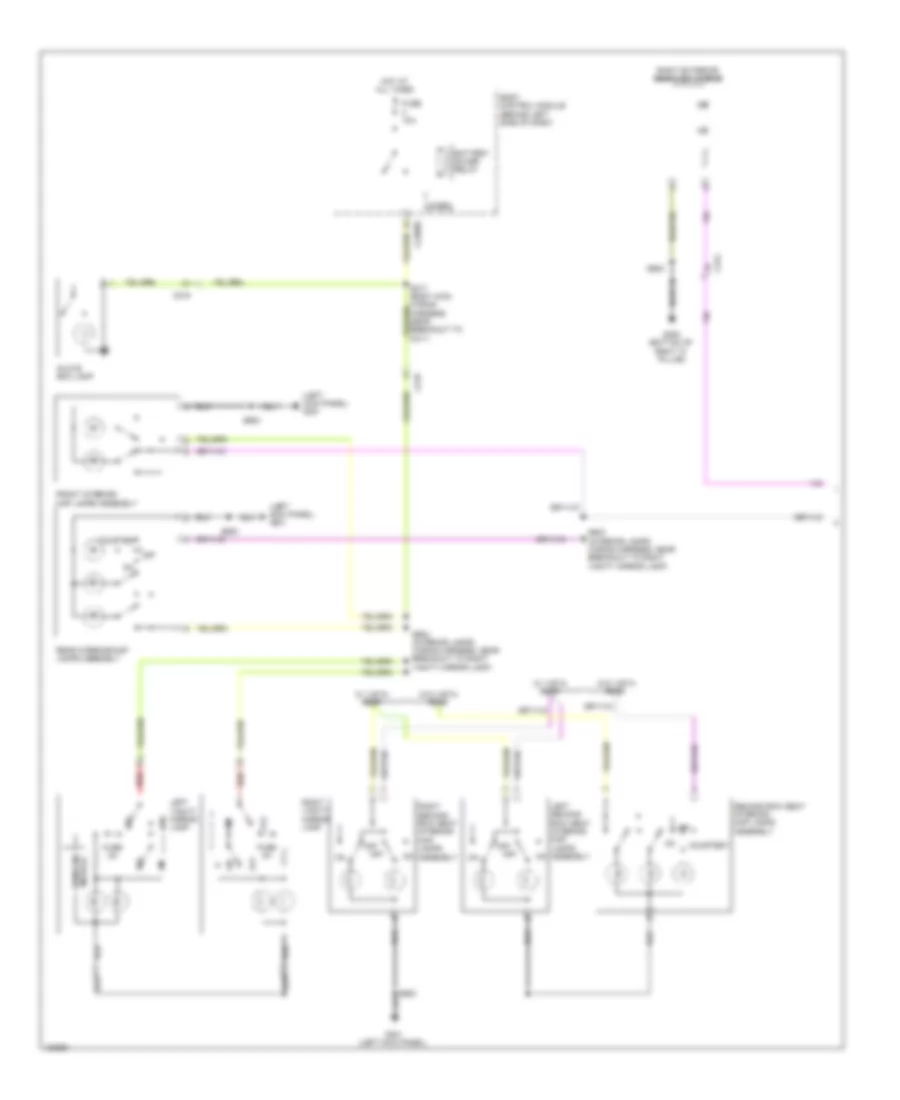 https://portal-diagnostov.com/license.html
Automotive Electricians Portal FZCO
Automotive Electricians Portal FZCO
https://portal-diagnostov.com/license.html
https://portal-diagnostov.com/license.html
Automotive Electricians Portal FZCO
Automotive Electricians Portal FZCOList of elements for Courtesy Lamps Wiring Diagram (1 of 3) for Ford Flex SEL 2014:
- (left kick panel) g301
- Assembly
- Battery saver relay
- Body control module (behind left side of dash)
- C215
- C219
- C2280d
- C312
- Courtesy
- Front interior/ map lamps assembly
- Fuse 10a
- Fuse 2a
- G300 (bottom of right "c" pillar)
- G301 (left kick panel)
- Glove box lamp
- Hot at all times
- Left second row seat interior/ map lamps assembly
- Left vanity mirror lamp
- Micro
- Module homelink
- Off
- Rear interior/map lamps assembly
- Red
- Right exterior rearview mirror
- Right second row seat interior/ map lamps
- Right vanity mirror lamp
- S600
- S900
- S902 (interior lamps wiring harness, near breakout to right vanity mirror lamp)
- S903 (interior lamps wiring harness, near breakout to right vanity mirror lamp)
- Second row seat interior/ map lamps assembly
- W/ vista roof
- W/o vista roof
Courtesy Lamps Wiring Diagram (2 of 3) for Ford Flex SEL 2014
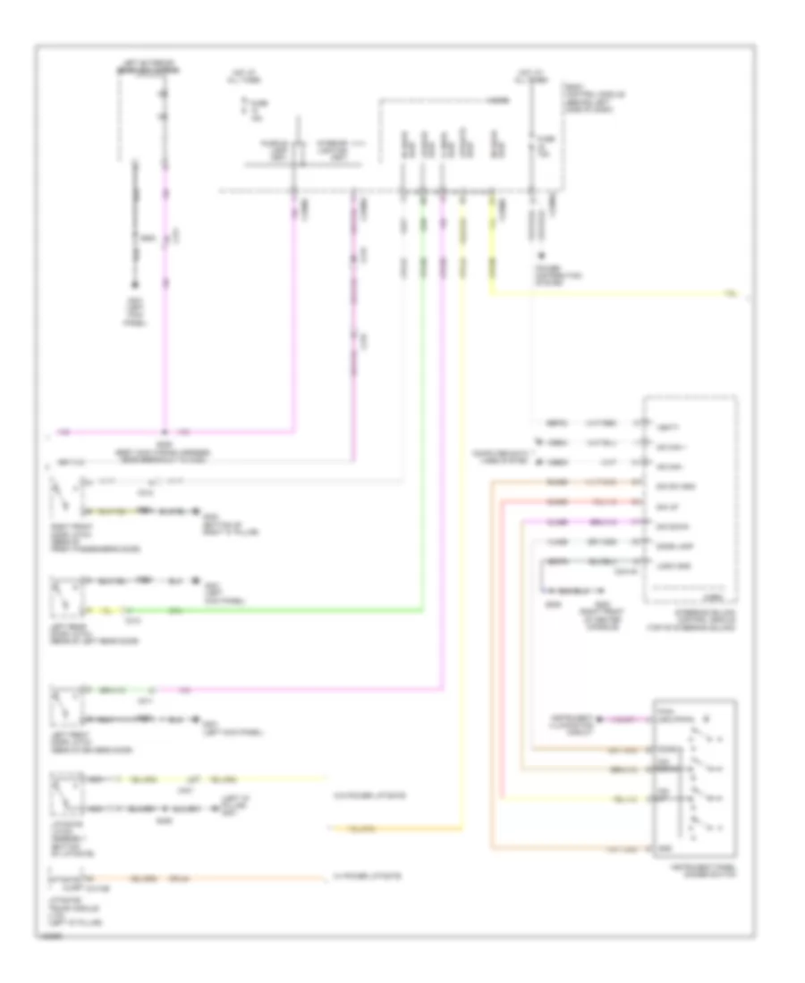 https://portal-diagnostov.com/license.html
Automotive Electricians Portal FZCO
Automotive Electricians Portal FZCO
https://portal-diagnostov.com/license.html
https://portal-diagnostov.com/license.html
Automotive Electricians Portal FZCO
Automotive Electricians Portal FZCOList of elements for Courtesy Lamps Wiring Diagram (2 of 3) for Ford Flex SEL 2014:
- (left "d" pillar) g401
- Ajar rf door
- Body control module (behind left side of dash)
- C215
- C219
- C2280a
- C2280c
- C2414a
- C311
- C312
- C313
- C431
- Cln55
- Cln56
- Computer data lines system
- Cpl26
- Cpl31
- Cpl36
- Cpl39
- Cpl44
- Dim down
- Dim sw gnd
- Dim up
- Dome
- Dome lamp
- Fuse 15a
- G200 (right front of center console)
- G300 (bottom of right "c" pillar)
- G301 (left kick panel)
- Gd375
- Gnd
- Hot at all times
- Hs can +
- Hs can -
- Instrument illumination circuit
- Instrument panel dimmer switch
- Interior lighting (fet)
- Left exterior rearview mirror
- Left front door latch (rear of driver's door)
- Left rear door latch (rear of left rear door)
- Lf door ajar
- Liftgate ajar
- Liftgate ajar c4174b
- Liftgate latch assembly (bottom of liftgate)
- Liftgate/ trunk module (ltm) (left "d" pillar)
- Logic gnd
- Lr door ajar
- Micro
- Nca
- Power distribution system
- Puddle lamp (fet)
- Pwm input
- Right front door latch (rear of front passenger's door)
- Rln29
- Rr door ajar
- S206
- S309 (body main wiring harness, near breakout to c340)
- S406
- S500
- S600
- S700
- Sbp23
- Steering column control module (top of steering column)
- Vbatt
- Vdb04
- Vdb05
- Vln36
- W/ power liftgate
- W/o power liftgate
Courtesy Lamps Wiring Diagram (3 of 3) for Ford Flex SEL 2014
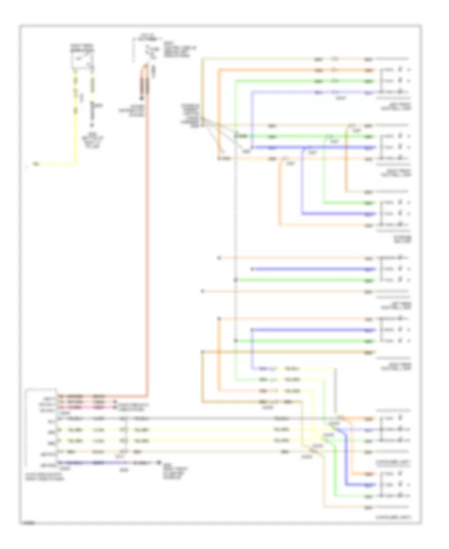 https://portal-diagnostov.com/license.html
Automotive Electricians Portal FZCO
Automotive Electricians Portal FZCO
https://portal-diagnostov.com/license.html
https://portal-diagnostov.com/license.html
Automotive Electricians Portal FZCO
Automotive Electricians Portal FZCOList of elements for Courtesy Lamps Wiring Diagram (3 of 3) for Ford Flex SEL 2014:
- (console ambient lighting wiring harness) s365
- Body control module (behind left side of dash)
- C214
- C2280a
- C228a
- C228c
- C3047
- C314
- C3249
- C327
- C3376
- Computer data lines system
- Cupholder lamp 1
- Cupholder lamp 2
- Fuse 10a
- G200 (right front of center console)
- G300 (bottom of right "c" pillar)
- Gd375
- Hot at all times
- Hvac module datc (right side of dash)
- Led gnd
- Led rtn
- Left front footwell lamp
- Left rear footwell lamp
- Ms can +
- Ms can -
- Power distribution system
- Red
- Right front footwell lamp
- Right rear door latch
- Right rear footwell lamp
- Rln44
- S205
- S364
- S366
- S367
- Sbp46
- Storage bin lamp
- Vbatt
- Vdb06
- Vdb07
- Vln48
- Vln49
- Vln50
Instrument Illumination Wiring Diagram for Ford Flex SEL 2014
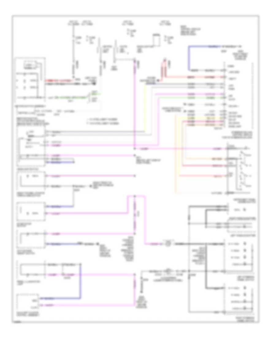 https://portal-diagnostov.com/license.html
Automotive Electricians Portal FZCO
Automotive Electricians Portal FZCO
https://portal-diagnostov.com/license.html
https://portal-diagnostov.com/license.html
Automotive Electricians Portal FZCO
Automotive Electricians Portal FZCOList of elements for Instrument Illumination Wiring Diagram for Ford Flex SEL 2014:
- (left kick panel) g301
- (not used)
- (right front of center console) g200
- Active park assist switch
- Aut01
- Auto 1
- Auxiliary climate control assembly
- Backlighting led (fet)
- Body control module (behind left side of dash)
- C214
- C215
- C2153d
- C218a
- C218b
- C2280a
- C2280b
- C2280c
- C2280d
- C2414a
- C311
- C3376
- Clf19
- Clf23
- Clf24
- Clf34
- Cln55
- Cln56
- Clockspring (under steering wheel)
- Computer data lines system
- Dim down
- Dim sw gnd
- Dim up
- Dome
- Dome lamp
- Front power liftgate open/close switch
- Fuse 10a
- Fuse 15a
- Fuse 7.5a
- G200 (right front of center console)
- Gd375
- Gnd
- Headlamp switch
- Hot at all times
- Hs can +
- Hs can -
- Illum
- Instrument panel dimmer switch
- Keypad illum
- Keypad illum (fet)
- Keypad switch assembly
- Left paddle shifter
- Left steering wheel switch
- Ligic gnd
- Logic
- Low
- Micro
- Nca
- Off
- Park
- Power distribution system
- Prndl illumination lamp
- Pwm input
- Red
- Remote function actuator (rfa) module (behind right side of dash)
- Right paddle shifter
- Right steering wheel switch
- Rln29
- S205
- S206
- S211 (behind left side of dash panel)
- S215 (body main wiring harness, near breakout to c211)
- S299 nca
- S341
- S343 (console wiring harness, near breakout to rear console power point)
- S500
- S502
- Sbp23
- Start/stop switch
- Steering column control module (top of steering column)
- Vbatt
- Vdb04
- Vdb05
- Vln36
- W/ intelligent access
- W/o intelligent access
- White led (fet)
MEMORY SYSTEMS
Memory Seat & Mirrors Wiring Diagram (1 of 3) for Ford Flex SEL 2014
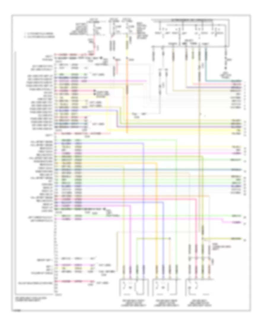 https://portal-diagnostov.com/license.html
Automotive Electricians Portal FZCO
Automotive Electricians Portal FZCO
https://portal-diagnostov.com/license.html
https://portal-diagnostov.com/license.html
Automotive Electricians Portal FZCO
Automotive Electricians Portal FZCOList of elements for Memory Seat & Mirrors Wiring Diagram (1 of 3) for Ford Flex SEL 2014:
- (not used)
- Adjustable pedals forward
- Aft
- Base backward
- Base forward
- Battery junction box (bjb) (left side of engine compt)
- Body control module (bcm) (behind left side of dash)
- C211
- C2280d
- C3052
- C311
- C339
- C340
- C341a
- C341b
- C341c
- C341d
- Cbx03
- Cbx05
- Computer data lines system
- Cpm04
- Cpm16
- Cpm17
- Cpm20
- Cpm21
- Cpm22
- Cpm26
- Cpm28
- Cpm29
- Cpm31
- Cpm33
- Cpm34
- Cpm39
- Cpp09
- Cps01
- Cps02
- Cps03
- Cps04
- Cps05
- Cps06
- Cps07
- Cps08
- Cps14
- Cps15
- Cps16
- Cps23
- Cps24
- Cps25
- Cps26
- Cps27
- Cps28
- Cps29
- Cps30
- Down
- Driver seat front height motor (under driver's seat)
- Driver seat rear height motor (under driver's seat)
- Driver seat recliner motor (driver's seat back)
- Driver's seat module (dsm) (under driver's seat)
- Drv mirr horz pot
- Drv mirr horz sw
- Drv mirr mtr dn/lt
- Drv mirr mtr horz rt
- Drv mirr mtr vert up
- Drv mirr vert pot
- Drv mirr vert sw
- Ext mirr pot rtn
- Exterior rear view mirror switch
- Fold/drive toggle
- Forward
- Front down
- Front up
- Fuse 15a
- Fuse 30a
- Fuse 7.5a
- G301 (left kick panel)
- Gd905
- Gd906
- Hall effect return
- Hall effect sense
- Hot at all times
- Left
- Left mirror fold in
- Left mirror fold out
- Logic gnd
- Lpm30
- Memory set +
- Mirr pot ret
- Ms can+
- Ms can-
- Pass mirr horz pot
- Pass mirr horz sw
- Pass mirr mtr dn/lt
- Pass mirr mtr horz rt
- Pass mirr mtr vert up
- Pass mirr vert pot
- Pass mirr vert sw
- Pwr gnd
- Rear down
- Rear up
- Recline down
- Recline up
- Right
- Rmp11
- Rpm30
- Rps13
- S305
- S326
- S356 (under driver's seat)
- S500
- S502
- Select
- Set 1
- Set 2
- Sw mirr rtn
- Vbatt
- Vdb06
- Vdb07
- Vpm35
- Vpm36
- Vpm37
- Vpm38
- Vps09
- Vps10
- Vps11
- Vps12
- W/ power fold mirror
- W/o power fold mirror
Memory Seat & Mirrors Wiring Diagram (2 of 3) for Ford Flex SEL 2014
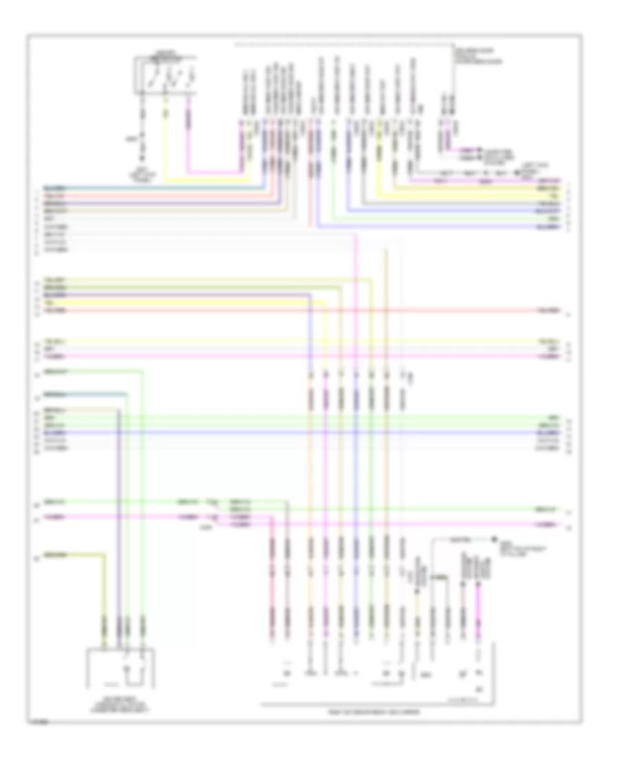 https://portal-diagnostov.com/license.html
Automotive Electricians Portal FZCO
Automotive Electricians Portal FZCO
https://portal-diagnostov.com/license.html
https://portal-diagnostov.com/license.html
Automotive Electricians Portal FZCO
Automotive Electricians Portal FZCOList of elements for Memory Seat & Mirrors Wiring Diagram (2 of 3) for Ford Flex SEL 2014:
- (left kick panel) g301
- Bsm
- C311
- C312
- C339
- C501a
- C501b
- Computer data lines system
- Cpm03
- Cpm16
- Cpm17
- Cpm20
- Cpm21
- Cpm23
- Cpm28
- Cpm29
- Cps15
- Cps16
- Defogger system
- Driver seat horizontal motor (under driver's seat)
- Driver's door module (in driver's door)
- Drv mirr horz pot
- Drv mirr horz sw
- Drv mirr mtr dn/lt
- Drv mirr mtr horz rt
- Drv mirr mtr vert up
- Drv mirr vert pot
- Drv mirr vert sw
- Ext mirror pot feed
- G300 (bottom of right "c" pillar)
- G301 (left kick panel)
- Gd233
- Gnd
- Interior lights
- Lpm30
- Mem recall sw 1
- Mem recall sw 2
- Memory set switch
- Mirr com sw
- Mirr pot ret
- Ms can +
- Ms can -
- Navigation system
- Pass mirr horz sw
- Pass mirr vert sw
- Right exterior rear view mirror
- Rpm30
- S305
- S500
- S600
- Sbp07
- Set 1
- Set 2
- System
- Vbatt
- Vdb06
- Vdb07
- Vpm35
- Vpm36
Memory Seat & Mirrors Wiring Diagram (3 of 3) for Ford Flex SEL 2014
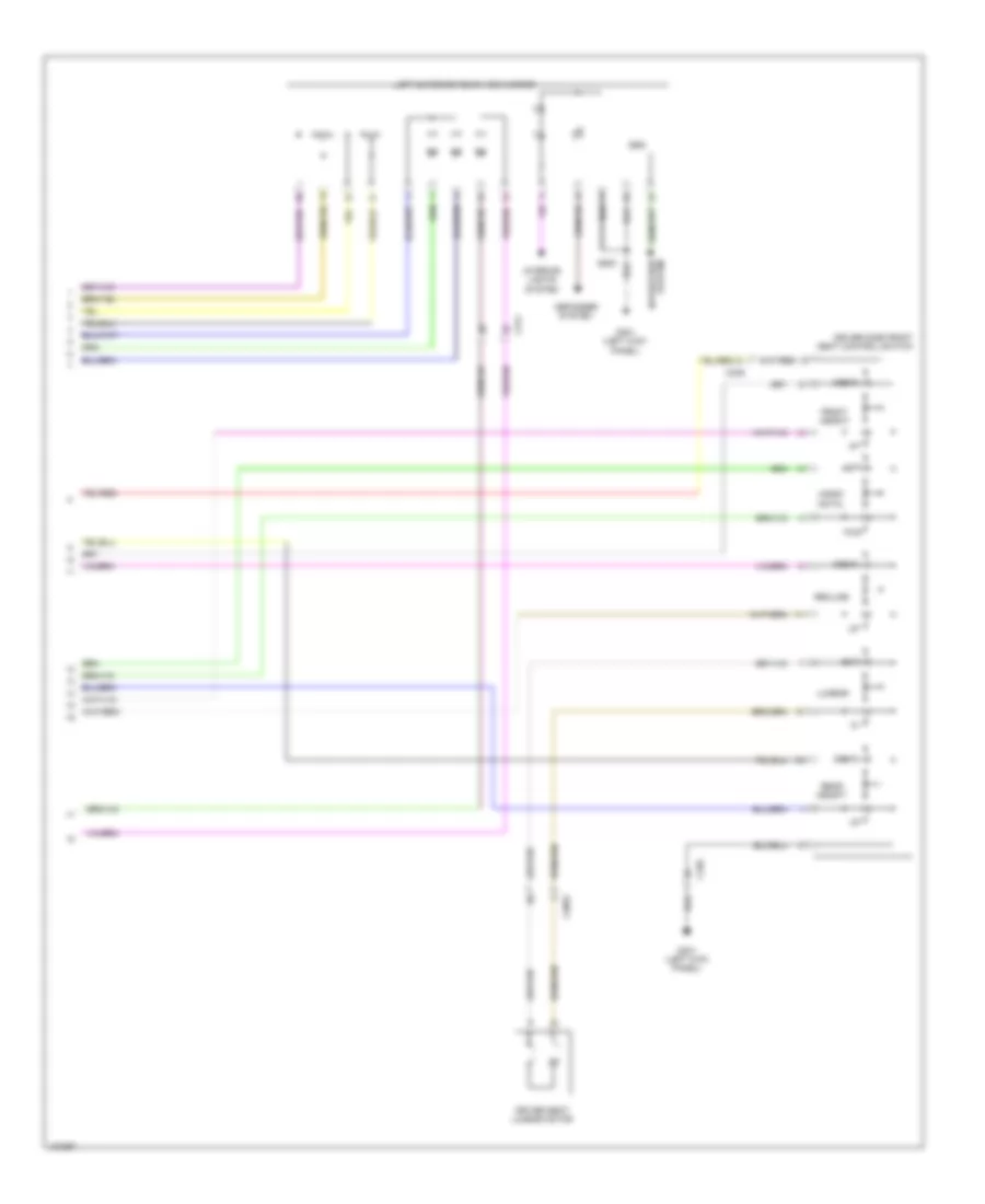 https://portal-diagnostov.com/license.html
Automotive Electricians Portal FZCO
Automotive Electricians Portal FZCO
https://portal-diagnostov.com/license.html
https://portal-diagnostov.com/license.html
Automotive Electricians Portal FZCO
Automotive Electricians Portal FZCOList of elements for Memory Seat & Mirrors Wiring Diagram (3 of 3) for Ford Flex SEL 2014:
- Aft
- Bsm
- C3052
- C311
- C339
- C340
- Defogger system
- Down
- Driver seat lumbar motor
- Driver side front seat control switch
- Front height
- Fwd
- G301 (left kick panel)
- Horiz-
- Interior lights system
- Left exterior rear view mirror
- Lumbar
- Ontal
- Out
- Rear height
- Recline
- S500
- System navigation
Steering Column Memory Wiring Diagram for Ford Flex SEL 2014
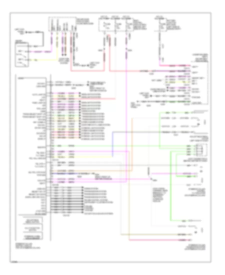 https://portal-diagnostov.com/license.html
Automotive Electricians Portal FZCO
Automotive Electricians Portal FZCO
https://portal-diagnostov.com/license.html
https://portal-diagnostov.com/license.html
Automotive Electricians Portal FZCO
Automotive Electricians Portal FZCOList of elements for Steering Column Memory Wiring Diagram for Ford Flex SEL 2014:
- (left kick panel) g301
- (main wiring harness, near breakout to accessory protocol interface module)
- (not used)
- (under driver's seat) driver seat module (dsm)
- A/d 1
- A/d 2
- A/d 3
- A/d 4
- Adj pdl mtr (fwd)
- Adjustable pedal motor (left side of dash)
- Adjustable pedal switch
- Auto lamp on
- Battery junction box (bjb) (left side of engine compt)
- Body control module (bcm) (behind left side of dash)
- C210
- C211
- C2280a
- C2280d
- C2414a
- C2414b
- C2414d
- C311
- C339
- C340
- C341a
- C341b
- C341c
- C341d
- C501b
- Cbx03
- Cbx05
- Cet42
- Cet43
- Clf19
- Clf21
- Clf23
- Clf24
- Cln55
- Cln56
- Cls34
- Com mtr
- Computer data lines system
- Cpp01
- Cpp04
- Cpp05
- Cpp22
- Cps14
- Cps15
- Cps16
- Crh04
- Cruise control system
- Crw15
- Dim down
- Dim sw gnd
- Dim up
- Dome lp
- Driver door module (ddm) (in driver's door)
- Fog lamp
- Frt wiper hi
- Fuse 15a
- Fuse 30a
- Fuse 7.5a
- G200 (right front of center console)
- G301 (left kick panel)
- Gd233
- Gd375
- Gd905
- Gd906
- Gnd
- Headlights system
- Horn
- Horn sw
- Horns system
- Hot at all times
- Hs can +
- Hs can -
- Instrument cluster system
- Interior lights system
- Joint connector 24 (behind center of dash)
- Lf sw gnd
- Lin
- Logic
- Logic gnd
- Low
- Lpp06
- Mem recall sw 2
- Memory set +
- Memory set switch
- Micro
- Ms can +
- Ms can -
- Multi-function switch
- Navigation & sound systems
- Nca
- Off
- Park lamp on
- Pdl hall sns sig
- Pwr gnd
- Re407
- Rh sw gnd
- Rln29
- Rpp06
- Rtn sig
- S202
- S206
- S212
- S305
- S500
- S502
- Sbp07
- Sbp23
- Sbp24
- Select sw down
- Select sw up
- Set 1
- Set 2
- Signal return cowl
- Sns rtn
- Steering column control module (top of steering column)
- Steering column control tilting motor (on steering column)
- Steering column telescoping motor (on steering column)
- Steering wheel angle sensor
- Sw 1 mem recall
- Tel mtr +/-
- Tel sns +
- Tilt mtr +/-
- Tilt sns +
- Trans select shift dw
- Trans select shift up
- Transmissions system
- Vbatt
- Vdb04
- Vdb05
- Vdb06
- Vdb07
- Vdn05
- Vln36
- Vpp08
- Vpp17
- Wiper/washer system
NAVIGATION
Blind Spot Information System Wiring Diagram for Ford Flex SEL 2014
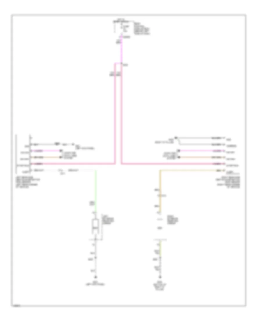 https://portal-diagnostov.com/license.html
Automotive Electricians Portal FZCO
Automotive Electricians Portal FZCO
https://portal-diagnostov.com/license.html
https://portal-diagnostov.com/license.html
Automotive Electricians Portal FZCO
Automotive Electricians Portal FZCOList of elements for Blind Spot Information System Wiring Diagram for Ford Flex SEL 2014:
- Address
- Alert
- Body control module (bcm) (behind left side of dash)
- Bsm
- C2280d
- C311
- C312
- Computer data lines system
- Fuse 10a
- G300 (bottom of right "c" pillar)
- G301 (left kick panel)
- G400 (right "d" pillar)
- Gnd
- Hot in start or run
- Left exterior rearview mirror
- Left rear side obstacle detection (sod) sensor (left rear corner of vehicle)
- Ms can+
- Ms can-
- Right exterior rearview mirror
- Right rear side obstacle detection (sod) sensor (right rear corner of vehicle)
- S303
- S305
- S500
- S600
- Start/run
Navigation Wiring Diagram, with Sony (1 of 2) for Ford Flex SEL 2014
 https://portal-diagnostov.com/license.html
Automotive Electricians Portal FZCO
Automotive Electricians Portal FZCO
https://portal-diagnostov.com/license.html
https://portal-diagnostov.com/license.html
Automotive Electricians Portal FZCO
Automotive Electricians Portal FZCOList of elements for Navigation Wiring Diagram, with Sony (1 of 2) for Ford Flex SEL 2014:
- (bottom of right "c" pillar) joint connector 19
- (left front of center console) g201
- (right "d" pillar) g400
- Am/fm
- Antenna module (top of right "d" pillar)
- Antenna pwr
- Audio control module (center of dash)
- Audio digital signal processing module (behind right rear quarterpanel)
- Audio in left +
- Audio in left -
- Audio in right +
- Audio in right -
- Body control module (bcm) (behind left side of dash)
- C212
- C240a
- C240b
- C2880d
- C311
- C312
- C313
- C314
- C4326a
- C4326b
- C4326c
- Ce336
- Coaxial cable
- Computer data lines system
- Dme17
- Enable
- Fc spkr +
- Fc spkr -
- Fuse 20a
- Gd351
- Gd374
- Gnd
- Hot at all times
- I can +
- I can -
- Instrument panel speaker
- Left a pillar speaker
- Left d pillar speaker
- Left front speaker
- Left rear speaker
- Lf spkr +
- Lf spkr -
- Lr spkr +
- Lr spkr -
- Lr sub +
- Lr sub -
- Nca
- Rc spkr +
- Rc spkr -
- Rf spkr +
- Rf spkr -
- Right a pillar speaker
- Right d pillar speaker
- Right front speaker
- Right rear speaker
- Rme01
- Rme02
- Rme06
- Rme07
- Rme08
- Rme09
- Rme10
- Rme11
- Rme12
- Rme17
- Rme18
- Rme30
- Rme52
- Rme53
- Rme80
- Rr spkr +
- Rr spkr -
- Rr sub +
- Rr sub -
- S400
- Sbp05
- Sbp29
- Sdars
- Sdl-h
- Sdl-l
- Shield
- Smcs
- Sme23
- Solid state
- Starting/ charging system
- Stereo l +
- Stereo l -
- Stereo r +
- Stereo r -
- Subwoofer
- Sync alert +
- Sync alert -
- Sync alert+
- Sync alert-
- Sync radio circuit
- V batt
- Vbatt
- Vdb13
- Vdb14
- Vme01
- Vme02
- Vme06
- Vme07
- Vme08
- Vme09
- Vme10
- Vme11
- Vme12
- Vme17
- Vme18
- Vme30
- Vme43
- Vme52
- Vme53
- Vme80
- Vme90
- Vme91
- W/ satellite radio
Navigation Wiring Diagram, with Sony (2 of 2) for Ford Flex SEL 2014
 https://portal-diagnostov.com/license.html
Automotive Electricians Portal FZCO
Automotive Electricians Portal FZCO
https://portal-diagnostov.com/license.html
https://portal-diagnostov.com/license.html
Automotive Electricians Portal FZCO
Automotive Electricians Portal FZCOList of elements for Navigation Wiring Diagram, with Sony (2 of 2) for Ford Flex SEL 2014:
- (behind left side of dash)
- (in steering wheel)
- Body control module (bcm)
- C218b
- C218c
- C2280a
- C2280b
- C2414d
- Clockspring (under steering wheel)
- Cls32
- Computer data lines system
- Down
- Front controls interface module (fcim) (center of dash)
- Fuse 10a
- Fuse 15a
- Fuse 20a
- G200 (right front of center console)
- G201 (left front of center console)
- Gd374
- Gd375
- Global positioning system module (gpsm) (behind center of dash)
- Gnd
- Hazard
- Hazard switch
- Hot at all times
- Hs can +
- Hs can -
- I can +
- I can -
- Interior lights system
- Left
- Left steering wheel switch
- Logic gnd c2414a
- Micro
- Ms can +
- Ms can -
- Nca
- Nca a/d 1 nca sw gnd right nca a/d 3 nca a/d 4 nca a/d 2
- Phone
- Ptt
- Red
- Right
- Right steering wheel switch
- S201
- S203
- S206
- S220 (in steering wheel)
- S221 (in steering wheel) nca
- S295
- S296
- Sbp09
- Sbp23
- Sbp29
- Seek +
- Seek -
- Steering column control module (sccm) (top of steering column)
- Vbatt
- Vdb04
- Vdb05
- Vdb06
- Vdb07
- Vdb13
- Vdb14
- Volume +
- Volume -
Navigation Wiring Diagram, without Sony (1 of 2) for Ford Flex SEL 2014
 https://portal-diagnostov.com/license.html
Automotive Electricians Portal FZCO
Automotive Electricians Portal FZCO
https://portal-diagnostov.com/license.html
https://portal-diagnostov.com/license.html
Automotive Electricians Portal FZCO
Automotive Electricians Portal FZCOList of elements for Navigation Wiring Diagram, without Sony (1 of 2) for Ford Flex SEL 2014:
- Am/fm
- Antenna module (top of right "d" pillar)
- Antenna pwr
- Audio control module (center of dash)
- Body control module (behind left side of dash)
- C212
- C2280a
- C2280b
- C240a
- C240b
- C311
- C312
- C313
- C314
- C523a
- C523b
- C652a
- C652b
- Ce336
- Cls32
- Coaxial cable
- Computer data lines system
- Fuse 10a
- Fuse 20a
- G201 (left front of center console)
- Gd374
- Gnd
- Hazard
- Hot at all times
- I can +
- I can -
- Instrument panel speaker (premium)
- Ip spkr +
- Ip spkr -
- Left a pillar speaker
- Left front speaker
- Left rear speaker
- Lf spkr +
- Lf spkr -
- Lr spkr +
- Lr spkr -
- Micro
- Nca
- Red
- Rf spkr +
- Rf spkr -
- Right a pillar speaker
- Right front speaker
- Right rear speaker
- Rme06
- Rme07
- Rme09
- Rme10
- Rme12
- Rme52
- Rme53
- Rme80
- Rr spkr +
- Rr spkr -
- S201
- S203
- Sbp29
- Sdars
- Sdl-h
- Sdl-l
- Smcs
- Solid state
- Starting/ charging system
- Stereo l +
- Stereo l -
- Stereo r +
- Stereo r -
- Sync alert+
- Sync alert-
- Sync radio circuit
- Vbatt
- Vdb13
- Vdb14
- Vme06
- Vme07
- Vme09
- Vme10
- Vme12
- Vme43
- Vme52
- Vme53
- Vme80
- Vme90
- Vme91
- W/ satellite radio
Navigation Wiring Diagram, without Sony (2 of 2) for Ford Flex SEL 2014
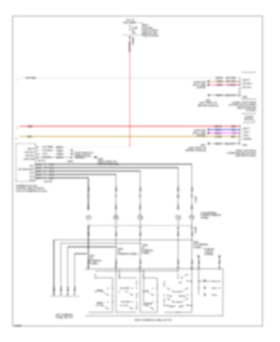 https://portal-diagnostov.com/license.html
Automotive Electricians Portal FZCO
Automotive Electricians Portal FZCO
https://portal-diagnostov.com/license.html
https://portal-diagnostov.com/license.html
Automotive Electricians Portal FZCO
Automotive Electricians Portal FZCOList of elements for Navigation Wiring Diagram, without Sony (2 of 2) for Ford Flex SEL 2014:
- (behind left side of dash)
- (in steering wheel)
- Body control module (bcm)
- C218b
- C218c
- C2280a
- C2414d
- Clockspring (under steering wheel)
- Cls32
- Computer data lines system
- Down
- Front controls interface module (fcim) (center of dash)
- Fuse 15a
- G200 (right front of center console)
- G201 (left front of center console)
- Gd374
- Gd375
- Global positioning system module (gpsm) (behind center of dash)
- Gnd
- Hazard
- Hazard switch
- Hot at all times
- Hs can +
- Hs can -
- I can +
- I can -
- Interior lights system
- Left
- Left steering wheel switch
- Logic gnd c2414a
- Ms can +
- Ms can -
- Nca
- Nca a/d 1 nca sw gnd right nca a/d 3 nca a/d 4 nca a/d 2
- Phone
- Ptt
- Red
- Right
- Right steering wheel switch
- S206
- S220 (in steering wheel)
- S221 (in steering wheel) nca
- S295
- S296
- Sbp09
- Sbp23
- Sbp29
- Seek +
- Seek -
- Steering column control module (sccm) (top of steering column)
- Vbatt
- Vdb04
- Vdb05
- Vdb06
- Vdb07
- Vdb13
- Vdb14
- Volume +
- Volume -
Parking Assistant Wiring Diagram for Ford Flex SEL 2014
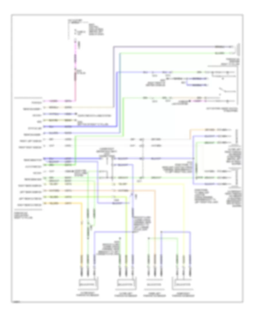 https://portal-diagnostov.com/license.html
Automotive Electricians Portal FZCO
Automotive Electricians Portal FZCO
https://portal-diagnostov.com/license.html
https://portal-diagnostov.com/license.html
Automotive Electricians Portal FZCO
Automotive Electricians Portal FZCOList of elements for Parking Assistant Wiring Diagram for Ford Flex SEL 2014:
- (backup alarm jumper wiring harness, near breakout to left license plate lamp) s417
- (dash panel to headlamp junction wiring harness, near breakout to left front fog lamp)
- (under right second row seat) joint connector 22
- Active park assist switch (if equipped)
- Auto park sw
- Body control module (bcm) (behind left side of dash)
- C211
- C212
- C214
- C2280d
- C405
- Cbp34
- Cmp02
- Cmp09
- Cmp18
- Computer data lines system
- Front left side sn
- Front right side sn
- Fuse 34 10a
- G200 (right front of center console)
- G300 (bottom of right "c" pillar)
- Gd348
- Gnd
- Hot in start or run
- Hs can+
- Hs can-
- Inner left parking aid sensor
- Inner right parking aid sensor
- Interior lights system
- Left rear inner sn
- Left rear outer sn
- Lmp07
- Nca
- Outer left front parking aid sensor (if equipped) (behind left end of front bumper)
- Outer left parking aid sensor
- Outer right front parking aid sensor (if equipped) (behind right end of front bumper)
- Outer right parking aid sensor
- Parking aid module (pam) (right "c" pillar)
- Parking aid speaker (right "c" pillar)
- Pwr run
- Rear sens gnd
- Rear sens pwr
- Rear sounder +
- Rear sounder -
- Right rear inner sn
- Right rear outer sn
- Rmp07
- Rmp09
- S134 (dash panel to headlamp junction wiring harness, near breakout to left front fog lamp)
- S135
- S341
- S408 (backup alarm jumper wiring harness, near breakout to left license plate lamp)
- Solid state
- Status led
- Vdb04
- Vdb05
- Vmp14
- Vmp15
- Vmp16
- Vmp17
- Vmp20
- Vmp21
Rear Camera Wiring Diagram for Ford Flex SEL 2014
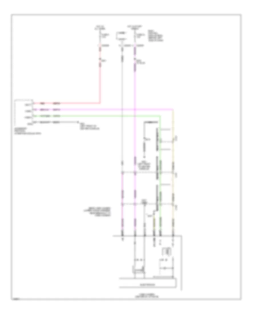 https://portal-diagnostov.com/license.html
Automotive Electricians Portal FZCO
Automotive Electricians Portal FZCO
https://portal-diagnostov.com/license.html
https://portal-diagnostov.com/license.html
Automotive Electricians Portal FZCO
Automotive Electricians Portal FZCOList of elements for Rear Camera Wiring Diagram for Ford Flex SEL 2014:
- (not used)
- (rear video camera jumper wiring harness, near breakout to video camera)
- Accessory protocol interface module (apim)
- Body control module (bcm) (behind left side of dash)
- C212
- C2280b
- C2280c
- C2280d
- C410
- C431
- Choke
- Electronics
- Fuse 34 10a
- Fuse 9 10a
- G201 (left front of center console)
- Gd374
- Gnd
- Hot at all times
- Hot in start or run
- Lin
- Lin 03
- Micro
- Nca
- Red
- Rmp19
- S201
- S218
- S303 (w/ blis)
- S407
- Sbp09
- Un comm
- Vbatt
- Vdn03
- Video camera (center of liftgate)
- Video+
- Video-
- Vmp19
POWER DISTRIBUTION
Power Distribution Wiring Diagram (1 of 5) for Ford Flex SEL 2014
 https://portal-diagnostov.com/license.html
Automotive Electricians Portal FZCO
Automotive Electricians Portal FZCO
https://portal-diagnostov.com/license.html
https://portal-diagnostov.com/license.html
Automotive Electricians Portal FZCO
Automotive Electricians Portal FZCOList of elements for Power Distribution Wiring Diagram (1 of 5) for Ford Flex SEL 2014:
- (left side of engine compt) battery junction box (bjb)
- (not used)
- (w/ hid headlamp)
- Anti-lock brake system (abs) module
- Auxiliary blower motor relay
- Battery
- Battery junction box (bjb) (left side of engine compt)
- Blower motor relay
- Brake pedal position (bpp) switch
- C102a
- C102b
- C144
- C1467b
- C1617a
- C1617b
- C1617c
- C1617d
- C210
- C211
- C214
- C219
- C228b
- C3050
- C312
- C3265a
- C340
- C341a
- C4174a
- Cooled seats
- Datc hvac module
- Driver seat module (dsm)
- Driver side front seat control switch
- Dual climate controlled seat module (dcsm)
- From body control module (bcm) (diagram 4 of 5)
- Front power point
- Front power point console
- Fuse 10a
- Fuse 20a
- Fuse 20a 30a
- Fuse 30a
- Fuse 40a
- Fuse 50a
- Fuse 5a
- Fusible link a (10 ga- red)
- Fusible link b (10 ga- red)
- G200 (right front of center console)
- G400 (right "d" pillar)
- Generator
- High current battery junction box (bjb) (left side of engine compt)
- High fan control (hfc) relay
- Left headlamp assembly
- Liftgate/ trunk module (ltm)
- Low fan control (lfc) relay
- Mega fuse 1 100a
- Mega fuse 2 60a
- Mega fuse 4 100a
- Passenger side front seat control switch
- Passenger side window control switch
- Power steering control module (pscm)
- Rear power point
- Rear power point console
- Rear window defrost relay
- Red
- Right headlamp assembly
- Roof opening panel module (if equipped)
- S127 (starter motor relay & battery ground wiring harness, near breakout to starter motor)
- S128 (starter motor relay & battery ground wiring harness, near breakout to starter motor)
- S129 (starter motor relay & battery ground wiring harness, near breakout to starter motor)
- S200
- S323
- S341
- Starter motor
- Starter relay
- Third row power seat relay
- To body control module (bcm) (diagram 3 of 5)
- To dc/ac inverter module (diagram 4 of 5)
- To fuse 60 (diagram 2 of 5)
- Trailer brake control (tbc) module
- Trailer tow battery charge relay
- W/ 10-way power seat
- W/ 6-way power seat
- W/ memory
- W/ rear heated/
- W/o memory
- W/o rear heated/
- Wiper relay
Power Distribution Wiring Diagram (2 of 5) for Ford Flex SEL 2014
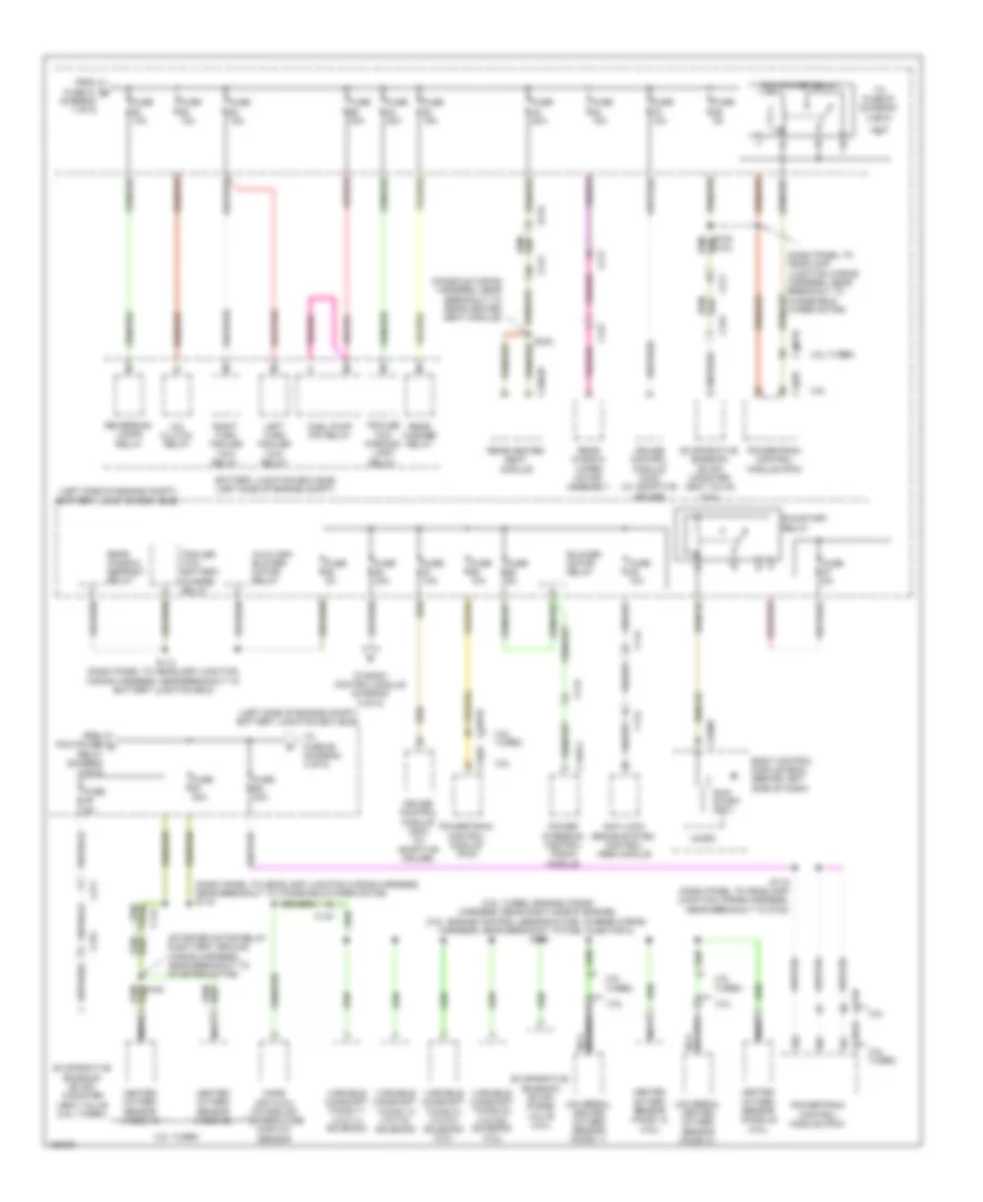 https://portal-diagnostov.com/license.html
Automotive Electricians Portal FZCO
Automotive Electricians Portal FZCO
https://portal-diagnostov.com/license.html
https://portal-diagnostov.com/license.html
Automotive Electricians Portal FZCO
Automotive Electricians Portal FZCOList of elements for Power Distribution Wiring Diagram (2 of 5) for Ford Flex SEL 2014:
- (3.5l turbo: engine wiring harness, rear right side of engine) (3.5l: engine control sensor & fuel charge wiring harness, near breakout to fuel injector 2) s146
- (3.5l)
- (console wiring harness, near breakout to rear heated seat module)
- (dash panel to headlamp junction wiring harness, near breakout to windshield wiper motor)
- (dash panel to headlamp junction wiring harness, near breakout to windshield wiper motor) s115
- (left side of engine compt) battery junction box (bjb)
- (starter motor relay & battery ground wiring harness, near breakout to starter motor)
- 3.5l
- 3.5l turbo
- A/c clutch relay
- Anti-lock brake system control (abs) module
- Auxiliary blower motor relay
- Battery junction box (bjb) (left side of engine compt)
- Blower motor relay
- Body control module (bcm) (behind left side of dash)
- C134
- C1381b
- C144
- C1467a
- C175b
- C210
- C211
- C214
- C2280f
- C315
- C3304b
- C431
- Cruise control module (ccm) (w/ adaptive cruise)
- Evaporative emission (evap) canister vent valve (3.5l turbo)
- Evaporative emission (evap) canister vent valve (3.5l)
- Evaporative emission (evap) purge valve (3.5l)
- From fuse 21 b (diagram 1 of 5)
- From pcm power d relay (diagram 2 of 5)
- Fuel pump (fp) relay
- Fuse 10a
- Fuse 15a
- Fuse 20a
- Fuse 30a
- Fuse 5a
- Heated oxygen sensor (ho2s) 12
- Heated oxygen sensor (ho2s) 12 (3.5l)
- Heated oxygen sensor (ho2s) 22
- Heated oxygen sensor (ho2s) 22 (3.5l)
- Left turn trailer tow relay
- Mass air flow/ intake air temperature (maf/iat) sensor
- Micro
- Nca
- Pcm power relay
- Power steering control (pscm) module
- Powertrain control module (pcm)
- Rear heated seat module
- Rear washer relay
- Rear window defrost relay
- Rear window wiper motor assembly
- Reversing lamps relay
- Right turn trailer tow relay
- Run/ start (fet)
- Run/start relay
- S112 (dash panel to headlamp junction wiring harness, near breakout to battery junction box)
- S116 (dash panel to headlamp junction wiring harness, near breakout to g102)
- S120
- S138 (3.5l)
- S342
- To body control module (diagram 5 of 5)
- To fuse 67 (diagram 2 of 5)
- To fuse 68 (diagram 3 of 5)
- Trailer tow battery charge relay
- Trailer tow parking lamp relay
- Universal heated oxygen sensor (ho2s) 11
- Universal heated oxygen sensor (ho2s) 21
- Variable camshaft timing 11 (vct11) solenoid
- Variable camshaft timing 12 (vct12) solenoid
- Variable camshaft timing 21 (vct21) solenoid (3.5l)
- Variable camshaft timing 22 (vct22) solenoid
Power Distribution Wiring Diagram (3 of 5) for Ford Flex SEL 2014
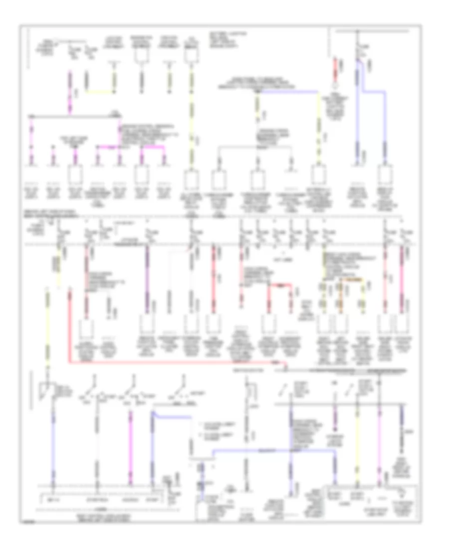 https://portal-diagnostov.com/license.html
Automotive Electricians Portal FZCO
Automotive Electricians Portal FZCO
https://portal-diagnostov.com/license.html
https://portal-diagnostov.com/license.html
Automotive Electricians Portal FZCO
Automotive Electricians Portal FZCOList of elements for Power Distribution Wiring Diagram (3 of 5) for Ford Flex SEL 2014:
- (3.5l turbo)
- (behind left side of dash) body control module (bcm)
- (dash panel to headlamp junction wiring harness, near breakout to windshield wiper motor) s108
- (main wiring harness, near breakout to accessory protocol interface module) s207
- (main wiring harness, near breakout to hvac module) s201
- (main wiring harness, near breakout to hvac module) s203
- (not used)
- (top left side of engine) s124
- 3.5l
- 3.5l turbo
- A/c clutch relay
- Acc
- Acc/run
- Access
- Accessory protocol interface module (apim)
- All wheel drive (awd) relay module
- Audio control module (acm)
- Battery junction box (bjb) (left side of engine compt)
- Body control module (bcm) (behind left side of dash)
- C134
- C1381b
- C144
- C175b
- C210
- C211
- C214
- C2153c
- C219
- C2280a
- C2280b
- C2280d
- C2280g
- C240a
- C2414a
- C311
- C3133
- C3134
- C339
- C4174a
- Coil on plug (cop) 1
- Coil on plug (cop) 2
- Coil on plug (cop) 3
- Coil on plug (cop) 4
- Coil on plug (cop) 5
- Coil on plug (cop) 6
- Driver side front power window motor
- Driver side front seat control switch (w/ memory seats)
- Engine fan control (fc) relay
- Externally controlled variable displacement compressor (evdc)
- Floor shifter
- From e fuse 69 (diagram 2 of 5)
- From high current battery junction box (bjb) (diagram 1 of 5)
- Front control/ display interface module (fcdim) (sync gen 1 (4.2 inches display)
- Front controls interface module (fcim)
- Fuel charge wiring harness, near breakout to electronic throttle control module) s131
- Fuse 10a
- Fuse 15a
- Fuse 20a
- Fuse 30a
- Fuse 5a
- G200 (right front of center console)
- Global positioning system module (gpsm)
- Head up display (hud) module (w/ adaptive cruise)
- High fan control (hfc) relay
- Ignition switch
- Ignition transformer capacitor 1 (3.5l turbo)
- Instrument panel cluster (ipc)
- Interior lights system
- Key in
- Key in ignition switch
- Left second row power fold seat motor
- Liftgate release relay
- Liftgate/ trunk module (ltm)
- Lock
- Low fan control (lfc) relay
- Micro
- Nca
- Not used
- Off
- Powertrain control module (pcm)
- Red
- Remote function actuator (rfa) module
- Right second row power fold seat motor
- Run
- S205
- Start
- Start/ stop 1
- Start/ stop 1 (active high)
- Start/ stop 2
- Start/ stop 2 (active low)
- Start/run
- Start/stop (led) (fet)
- Start/stop switch
- Steering column control module (sccm)
- Sync gen 1 (4.2 inches display)
- Tire pressure monitor (tpm) module
- To fuse 5 (diagram 4 of 5)
- To keypad illu (fet) (diagram 5 of 5)
- Turbocharger bypass valve (tcby) (3.5l turbo)
- Turbocharger bypass valve 2 (tcby2)
- Turbocharger wastegate regulating valve solenoid (3.5l turbo)
- W/ intelligent
- W/ rear folding seats
- W/o intelligent
Power Distribution Wiring Diagram (4 of 5) for Ford Flex SEL 2014
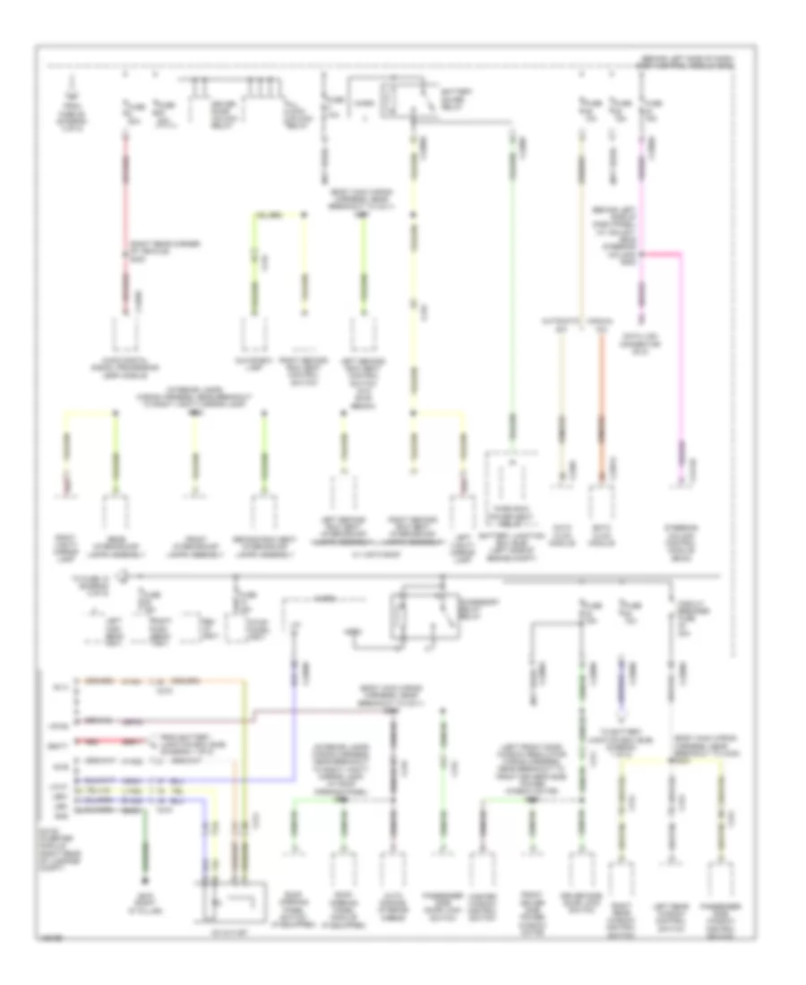 https://portal-diagnostov.com/license.html
Automotive Electricians Portal FZCO
Automotive Electricians Portal FZCO
https://portal-diagnostov.com/license.html
https://portal-diagnostov.com/license.html
Automotive Electricians Portal FZCO
Automotive Electricians Portal FZCOList of elements for Power Distribution Wiring Diagram (4 of 5) for Ford Flex SEL 2014:
- (behind left side of dash panel) (w/ adjust- able steering column) s202
- (behind left side of dash) body control module (bcm)
- (body main wiring harness, near breakout to c211) s216
- (body main wiring harness, near breakout to c211) s217
- (body main wiring harness, near breakout to c340) s304
- (interior lamps wiring harness, near breakout to right vanity mirror lamp) (w/ roof opening panel) s901
- (interior lamps wiring harness, near breakout to right vanity mirror lamp) s902
- (left front door window regulator wiring harness, near breakout to front driver's side power window motor) s503
- (not used)
- (right rear corner of vehicle) s400
- Ac a
- Ac outlet
- Ac-b
- Accessory delay relay
- Adrc
- All lock/ unlock relay
- Audio digital signal processing (dsp) module
- Auto dimming interior mirror
- Automatic a/c
- Battery junction box (bjb) (left side of engine compt)
- Battery saver relay
- C214
- C215
- C219
- C2280a
- C2280b
- C2280d
- C2280f
- C228a
- C2357a
- C2414b
- C311
- C312
- C313
- C314
- C4326c
- Cbp32
- Circuit breaker fuse 30a
- Data link connector (dlc)
- Datc hvac module
- Dc/ac inverter module (right rear of luggage compt)
- Driver door unlock relay
- Driver side door lock switch
- Emtc hvac module
- From battery junction box (bjb) (diagram 1 of 5)
- From fuse 26 (diagram 3 of 5)
- Front driver side power window motor
- Front interior/map lamps assembly
- Fuse 10a
- Fuse 15a
- Fuse 20a
- G400 (right "d" pillar)
- Gd351
- Glove box lamp
- Gnd
- Hya01
- Hya02
- Led+
- Led-
- Left high beam (fet)
- Left rear window control switch
- Left second row seat control switch (w/o 60/40 bench)
- Left second row seat interior/map lamps assembly
- Left vanity mirror lamp
- Lin
- Lin 01
- Lya03
- Manual a/c
- Master window control switch
- Micro
- Passenger side door lock switch
- Passenger side window control switch
- Rear interior/map lamps assembly
- Red
- Rev lp (fet)
- Right high beam (fet)
- Right rear window control switch
- Right second row seat control switch
- Right second row seat interior/map lamps assembly
- Right vanity mirror lamp
- Roof opening panel module (if equipped)
- Roof opening panel switch (if equipped)
- Rya03
- Sbb17
- Second row seat interior/map lamps assembly
- Steering column control module (sccm)
- Stop/ chmsl (fet)
- Third row power seat relay
- To battery junction box (bjb) (diagram 1 of 5)
- To fuse 18 (diagram 5 of 5)
- Vbatt
- Vdn01
- Vpwr
- W/ vista roof
Power Distribution Wiring Diagram (5 of 5) for Ford Flex SEL 2014
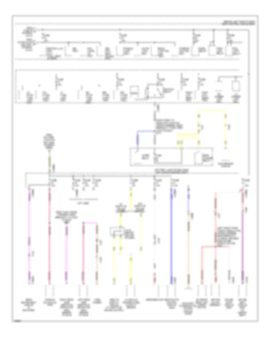 https://portal-diagnostov.com/license.html
Automotive Electricians Portal FZCO
Automotive Electricians Portal FZCO
https://portal-diagnostov.com/license.html
https://portal-diagnostov.com/license.html
Automotive Electricians Portal FZCO
Automotive Electricians Portal FZCOList of elements for Power Distribution Wiring Diagram (5 of 5) for Ford Flex SEL 2014:
- (behind left side of dash) body control module (bcm)
- (body main wiring harness, near breakout to c340) (w/ blis) s303
- (dash panel to headlamp junction wiring harness, near breakout to battery junction box) s113
- 3rd row seat enable (fet)
- Back lighting led (fet)
- Battery junction box (bjb) (left side of engine compt)
- Bsi (fet)
- C211
- C214
- C215
- C219
- C2280b
- C2280d
- C2280e
- C2280f
- C3050
- C310a
- C311
- C3304b
- C339
- C341b
- C410
- C431
- C501b
- Driver door module (ddm)
- Driver seat module (dsm) (w/ memory seat)
- Exterior rear view mirror switch
- Fog lamp relay
- From battery junction box (bjb) (diagram 2 of 5)
- From fuse 39 k (diagram 4 of 5)
- From start/stop h (led) (fet) (diagram 3 of 5)
- Fuse 10a
- Fuse 15a
- Fuse 20a
- Fuse 5a
- Fuse 7.5a
- Head up display module (w/ adaptive) cruise control)
- Horn relay
- In-vehicle temperature/ humidity sensor
- Interior lighting (fet)
- J/c 24 (behind center of dash)
- Keypad illum (fet) (w/o intelligent access)
- Keypad switch assembly
- Left low beam (fet)
- Left rear side obstacle detection (sod) sensor (w/ blis)
- Lf turn lamp (fet)
- Lh corner lamp (fet)
- Lr stop/ turn lamp (fet)
- Lr turn lamp (fet)
- Micro
- Not used
- Occupant classification system module (ocsm)
- Park lamp relay
- Parking aid module (pam)
- Pcm wake up (fet)
- Puddle lamp (fet)
- Rain sensor module
- Rear heated seat module (if equipped)
- Rear washer relay
- Red
- Refrigerator
- Restraints control module (rcm)
- Rf turn lamp (fet)
- Rh corner lamp (fet)
- Right low beam (fet)
- Right rear side obstacle detection (sod) sensor (w/ blis)
- Rr stop/ turn lamp (fet)
- Rr turn lamp (fet)
- Run/acc relay
- S502
- Video camera
- W/ adaptive cruise control
- W/o adaptive cruise control
- White light (fet)
- Wiper relay
POWER DOOR LOCKS
Power Door Locks Wiring Diagram, with Intelligent Access (1 of 2) for Ford Flex SEL 2014
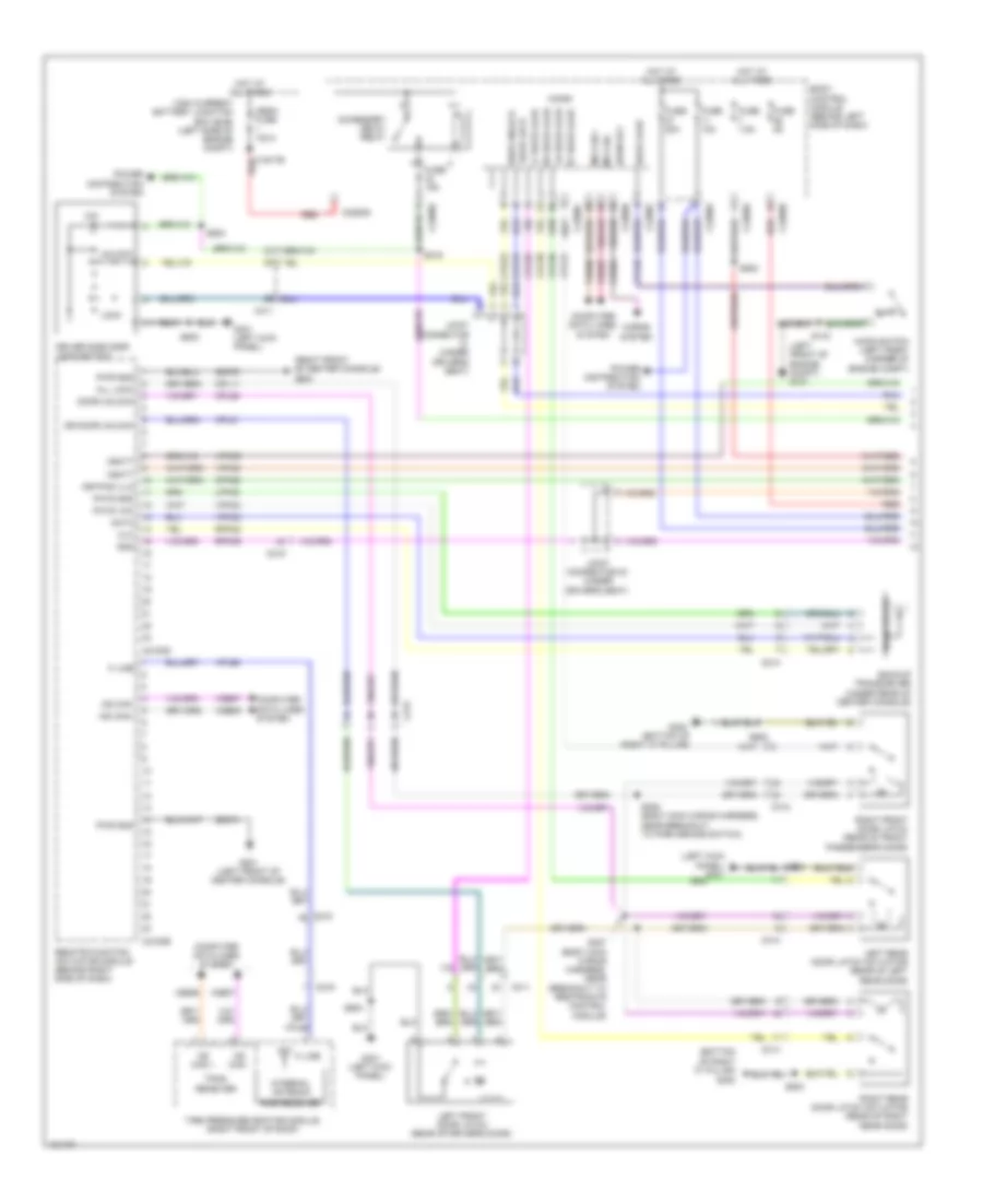 https://portal-diagnostov.com/license.html
Automotive Electricians Portal FZCO
Automotive Electricians Portal FZCO
https://portal-diagnostov.com/license.html
https://portal-diagnostov.com/license.html
Automotive Electricians Portal FZCO
Automotive Electricians Portal FZCOList of elements for Power Door Locks Wiring Diagram, with Intelligent Access (1 of 2) for Ford Flex SEL 2014:
- (bottom of right "c" pillar)
- (bottom of right "c" pillar) g300
- (left front of engine compt) g101
- (left kick panel) g301
- (right front of center console) g200
- (x2)
- Accessory delay relay
- Ajar
- All lock
- Backup transceiver (under rear of center console)
- Body control module (behind left side of dash)
- C1617b
- C214
- C215
- C2153d
- C2153e
- C219
- C2280a
- C2280b
- C2280c
- C2280d
- C2280f
- C2280g
- C311
- C312
- C313
- C314
- Clk
- Computer data lines system
- Cpk19
- Cpk23
- Cpk28
- Cpl11
- Cpl25
- Cpl26
- Cpl31
- Cpl36
- Cpl39
- Cpl51
- Cpl52
- Crh04
- Data
- Door lock
- Door unlock
- Dr door unlock
- Driver side door lock switch
- Fuse 10a
- Fuse 15a
- Fuse 20a
- Fuse 5a
- Fuse 7.5a
- G201 (left front of center console)
- G300
- G301 (left kick panel)
- Gd374
- Gd375
- Gnd
- High current battery junction box (bjb) (left side of engine compt)
- Hood ajar
- Hood switch (left front corner of engine compt)
- Horn rly
- Horns system
- Hot at all times
- Internal antenna
- Joint connector (under driver's seat)
- Joint connector 23 (under driver's seat)
- K line
- Keypad illm
- Left front door latch (rear of driver's door)
- Left rear door latch actuator (rear of left rear door)
- Lf door ajar
- Lock
- Lpk32
- Lr door ajar
- Mega fuse 100a
- Micro
- Ms can +
- Ms can -
- Ms can+
- Ms can-
- Pats gnd
- Pats vcc
- Power distribution system
- Pwr gnd
- Red
- Remote function actuator module (behind right side of dash)
- Rf door ajar
- Right front door latch (rear of front passenger's door)
- Right rear door latch actuator (rear of right rear door)
- Rke receiver
- Rpk32
- Rpk39
- Rr door ajar
- S143
- S216
- S307 (body main wiring harness, near breakout to restraints control module)
- S308 (body main wiring harness, near breakout to park brake switch)
- S500
- S502
- S503
- S600
- S800
- Solid state
- Tire pressure monitor module (right front of roof)
- Tpms receiver
- Unlock
- Vbatt
- Vdb06
- Vdb07
- Vpk32
- Vpk33
- Vpk39
- Vpk40
- Vpl56
Power Door Locks Wiring Diagram, with Intelligent Access (2 of 2) for Ford Flex SEL 2014
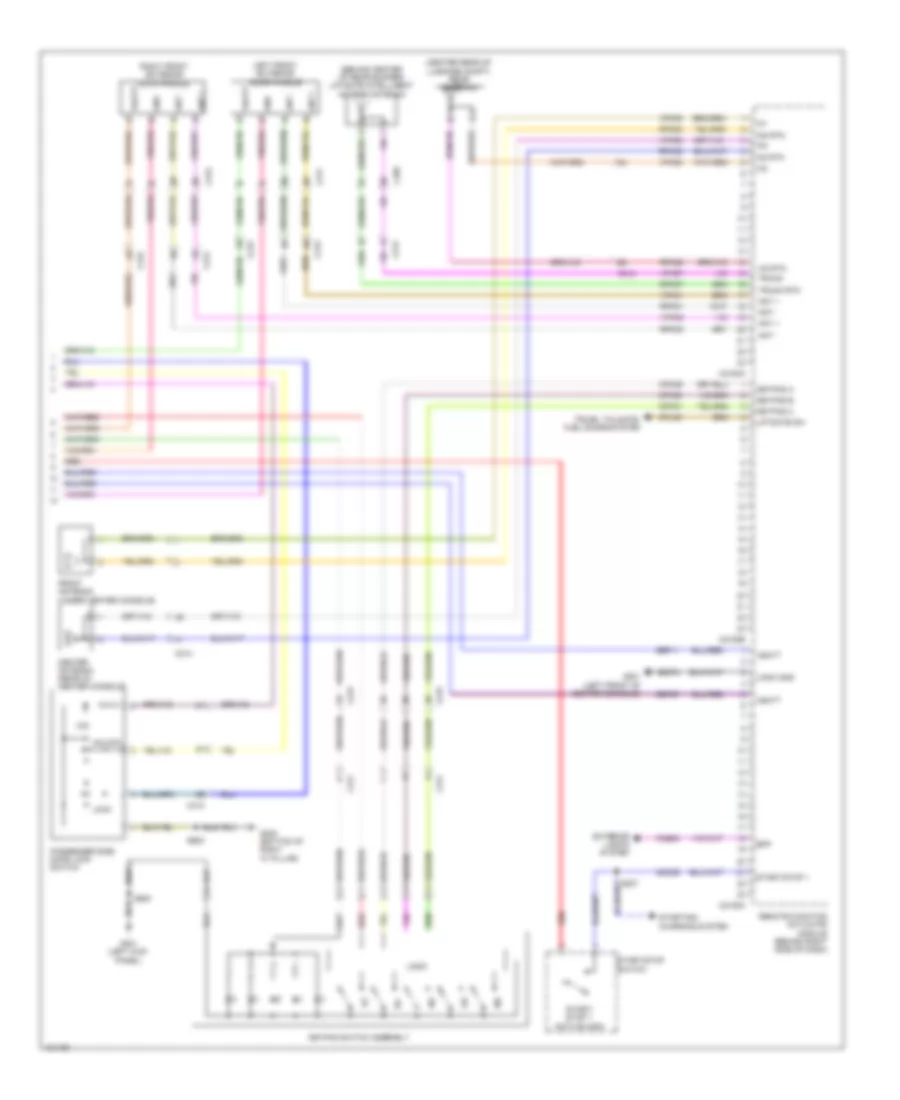 https://portal-diagnostov.com/license.html
Automotive Electricians Portal FZCO
Automotive Electricians Portal FZCO
https://portal-diagnostov.com/license.html
https://portal-diagnostov.com/license.html
Automotive Electricians Portal FZCO
Automotive Electricians Portal FZCOList of elements for Power Door Locks Wiring Diagram, with Intelligent Access (2 of 2) for Ford Flex SEL 2014:
- (behind center of rear bumper) liftgate intelligent access antenna
- (center rear of luggage compt) rear antenna
- (x2)
- 1/2
- 3/4
- 5/6
- 7/8
- 9/0
- Ant +
- Ant -
- Bpp
- C212
- C214
- C215
- C2153a
- C2153b
- C2153c
- C311
- C312
- C405
- Ccb08
- Cdc35
- Center antenna (rear of center console)
- Cpk29
- Cpk30
- Cpk31
- Cpl45
- Exterior lights system
- Front antenna (under center console)
- G201 (left front of center console)
- G300 (bottom of right "c" pillar)
- G301 (left kick panel)
- Gd374
- Gnd
- Ia1
- Ia2
- Ia2 rtn
- Ia3
- Ia3 rtn
- Ian rtn
- Keypad a
- Keypad b
- Keypad c
- Keypad switch assembly
- Left front exterior door handle
- Liftgate sw
- Lock
- Logic
- Logic gnd
- Passenger side door lock switch
- Red
- Remote function actuator module (behind right side of dash)
- Right front exterior door handle
- Rpk01
- Rpk02
- Rpk05
- Rpk06
- Rpk07
- Rpk08
- S207
- S500
- S600
- Sbp11
- Sbp27
- Start/ stop 1 (active high)
- Start/stop 1
- Start/stop switch
- Starting/ charging system
- Trunk
- Trunk rtn
- Trunk, tailgate, fuel doors system
- Unlock
- Vbatt
- Vpk01
- Vpk02
- Vpk05
- Vpk06
- Vpk07
- Vpk08
Power Door Locks Wiring Diagram, without Intelligent Access (1 of 2) for Ford Flex SEL 2014
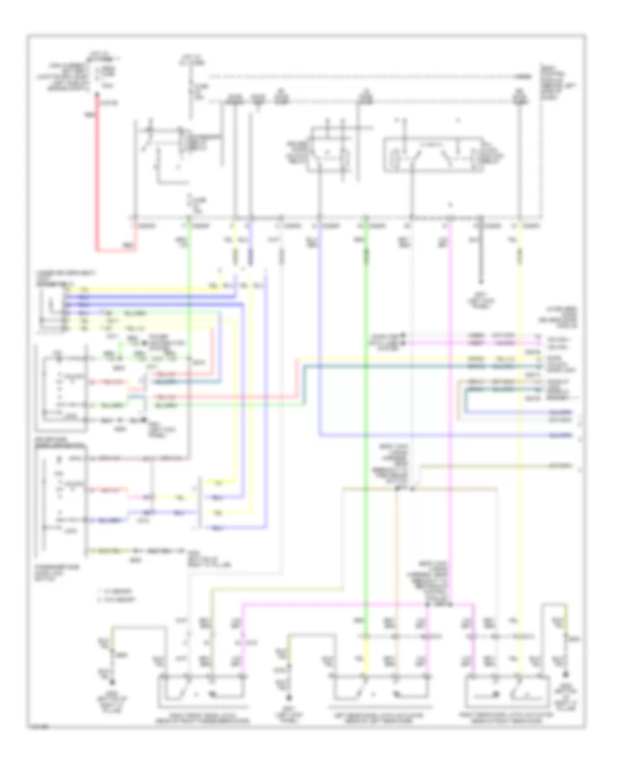 https://portal-diagnostov.com/license.html
Automotive Electricians Portal FZCO
Automotive Electricians Portal FZCO
https://portal-diagnostov.com/license.html
https://portal-diagnostov.com/license.html
Automotive Electricians Portal FZCO
Automotive Electricians Portal FZCOList of elements for Power Door Locks Wiring Diagram, without Intelligent Access (1 of 2) for Ford Flex SEL 2014:
- (body main wiring harness, near breakout to park brake switch) s308
- (body main wiring harness, near breakout to restraints control module) s307
- (in driver's door) driver's door module
- (under driver's seat) joint connector 21
- (x2)
- Accessory delay relay
- All lock/ unlock relay
- Body control module (behind left side of dash)
- C1617b
- C2280c
- C2280d
- C2280g
- C311
- C312
- C313
- C314
- C501a
- C501b
- Computer data lines system
- Cpk19
- Cpk23
- Cpl11
- Cpl31
- Cpl36
- Cpl39
- Cpl51
- Door lock
- Door mt lock door mt unlock
- Door unlock
- Door unlock door lock
- Driver door unlock relay
- Driver side door lock switch
- Fuse 15a
- Fuse 20a
- G300 (bottom of right "c" pillar)
- G301 (left kick panel)
- High current battery junction box (bjb) (left side of engine compt)
- Hot at all times
- Left rear door latch actuator (rear of left rear door)
- Lock
- Lr door ajar
- Mega fuse 100a
- Micro
- Ms can +
- Ms can -
- Passenger side door lock switch
- Red
- Rf door ajar
- Right front door latch (rear of front passenger's door)
- Right rear door latch actuator (rear of right rear door)
- Rr door ajar
- S216
- S500
- S503
- S600
- S700
- S800
- Unlock
- Vdb06
- Vdb07
- W/ memory
- W/o memory
Power Door Locks Wiring Diagram, without Intelligent Access (2 of 2) for Ford Flex SEL 2014
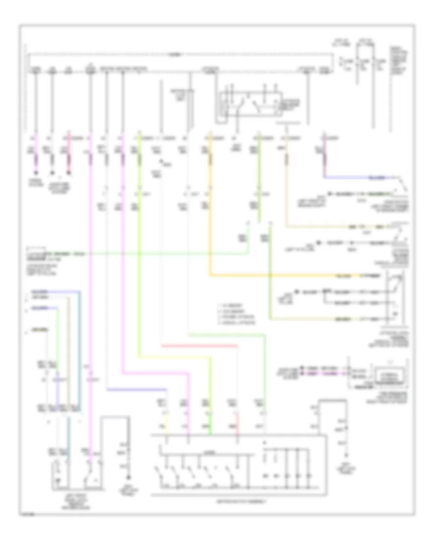 https://portal-diagnostov.com/license.html
Automotive Electricians Portal FZCO
Automotive Electricians Portal FZCO
https://portal-diagnostov.com/license.html
https://portal-diagnostov.com/license.html
Automotive Electricians Portal FZCO
Automotive Electricians Portal FZCOList of elements for Power Door Locks Wiring Diagram, without Intelligent Access (2 of 2) for Ford Flex SEL 2014:
- (not used)
- 1/2
- 3/4
- 5/6
- 7/8
- 9/0
- Ajar
- Body control module (behind left side of dash)
- C2280b
- C2280c
- C2280d
- C2280f
- C311
- C4174b
- C431
- Computer data lines system
- Cpk29
- Cpk30
- Cpl45
- Cpl84
- Fuse 10a
- Fuse 15a
- Fuse 7.5a
- G101 (left front of engine compt)
- G301 (left kick panel)
- G401 (left "d" pillar)
- Hood ajar
- Hood switch (left front corner of engine compt)
- Horn rly
- Horns system
- Hot at all times
- Internal antenna rke receiver
- Keypad a
- Keypad b
- Keypad c
- Keypad illum (fet)
- Keypad switch assembly
- Left front door latch (rear of driver's door)
- Lf door ajar
- Liftgate ajar
- Liftgate latch assembly (manual liftgate) (bottom of liftgate)
- Liftgate release
- Liftgate release relay
- Liftgate release switch (manual liftgate)
- Liftgate sw
- Liftgate/trunk module (ltm) (left "d" pillar)
- Manual liftgate
- Micro
- Ms can+
- Ms can-
- Nca
- Power liftgate
- Red
- S143
- S406
- S500
- S502
- Tire pressure monitor module (right front of roof)
- Tpms receiver
- Vdb06
- Vdb07
- W/ memory
- W/o memory
POWER MIRRORS
Electrochromic Mirror Wiring Diagram for Ford Flex SEL 2014
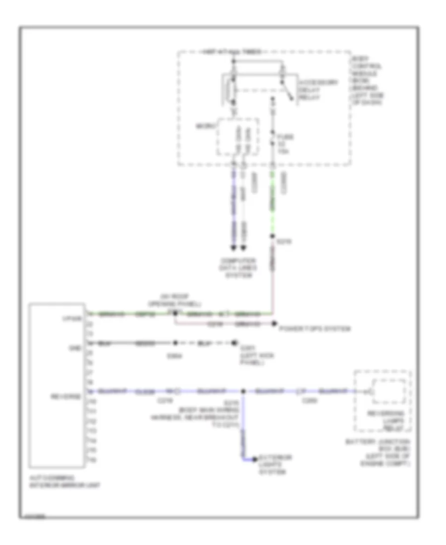 https://portal-diagnostov.com/license.html
Automotive Electricians Portal FZCO
Automotive Electricians Portal FZCO
https://portal-diagnostov.com/license.html
https://portal-diagnostov.com/license.html
Automotive Electricians Portal FZCO
Automotive Electricians Portal FZCOList of elements for Electrochromic Mirror Wiring Diagram for Ford Flex SEL 2014:
- (w/ roof opening panel) s901
- Accessory delay relay
- Auto-dimming interior mirror unit
- Battery junction box (bjb) (left side of engine compt)
- Body control module (bcm) (behind left side of dash)
- C219
- C2280d
- C2280f
- C260
- Cbp32
- Cls28
- Computer data lines system
- Exterior lights system
- Fuse 15a
- G301 (left kick panel)
- Gd233
- Gnd
- Hot at all times
- Hs can+
- Hs can-
- Micro
- Power tops system
- Reverse
- Reversing lamps relay
- S216
- S904
- Vdb04
- Vdb05
- Vpwr
Power Mirrors Wiring Diagram for Ford Flex SEL 2014
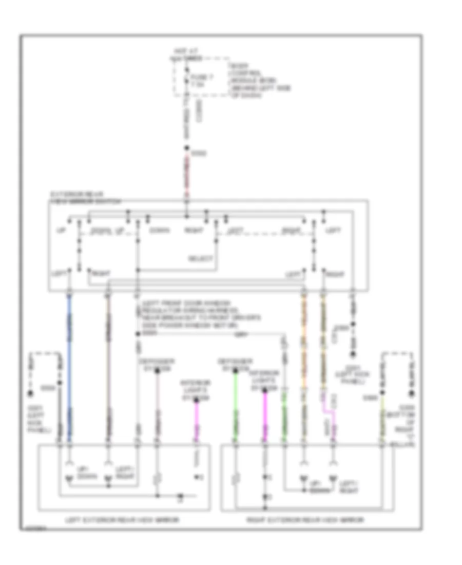 https://portal-diagnostov.com/license.html
Automotive Electricians Portal FZCO
Automotive Electricians Portal FZCO
https://portal-diagnostov.com/license.html
https://portal-diagnostov.com/license.html
Automotive Electricians Portal FZCO
Automotive Electricians Portal FZCOList of elements for Power Mirrors Wiring Diagram for Ford Flex SEL 2014:
- Body control module (bcm) (behind left side of dash)
- C2280d
- C311
- C312
- Defogger system
- Down
- Exterior rear view mirror switch
- Fuse 7 7.5a
- G300 (bottom of right "c" pillar)
- G301 (left kick panel)
- Hot at all times
- Interior lights system
- Left
- Left exterior rear view mirror
- Left/ right
- Left/ right m
- Right
- Right exterior rear view mirror
- S500
- S502
- S600
- Select
- Up/ down
POWER SEATS
Adjustable Pedal Wiring Diagram for Ford Flex SEL 2014
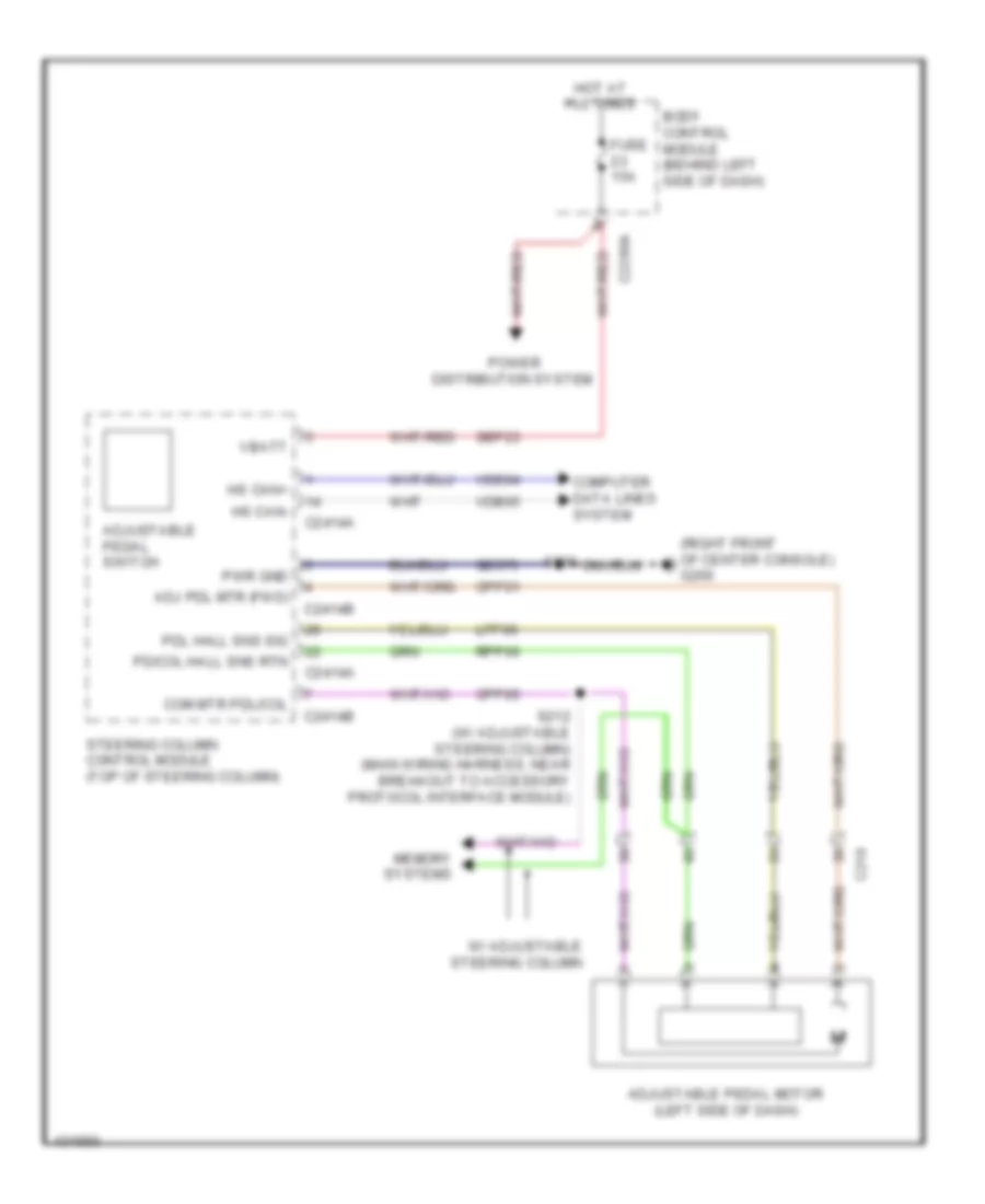 https://portal-diagnostov.com/license.html
Automotive Electricians Portal FZCO
Automotive Electricians Portal FZCO
https://portal-diagnostov.com/license.html
https://portal-diagnostov.com/license.html
Automotive Electricians Portal FZCO
Automotive Electricians Portal FZCOList of elements for Adjustable Pedal Wiring Diagram for Ford Flex SEL 2014:
- (right front of center console) g200
- Adj pdl mtr (fwd)
- Adjustable pedal motor (left side of dash)
- Adjustable pedal switch
- Body control module (behind left side of dash)
- C210
- C2280a
- C2414a
- C2414b
- Com mtr pdl/col
- Computer data lines system
- Cpp01
- Cpp05
- Fuse 15a
- Gd375
- Hot at all times
- Hs can+
- Hs can-
- Lpp06
- Memory systems
- Pd/col hall sns rtn
- Pdl hall sns sig
- Power distribution system
- Pwr gnd
- Rpp06
- S206
- S212 (w/ adjustable steering column) (main wiring harness, near breakout to accessory protocol interface module)
- Sbp23
- Steering column control module (top of steering column)
- Vbatt
- Vdb04
- Vdb05
- W/ adjustable steering column
Climate Control Seats Wiring Diagram for Ford Flex SEL 2014
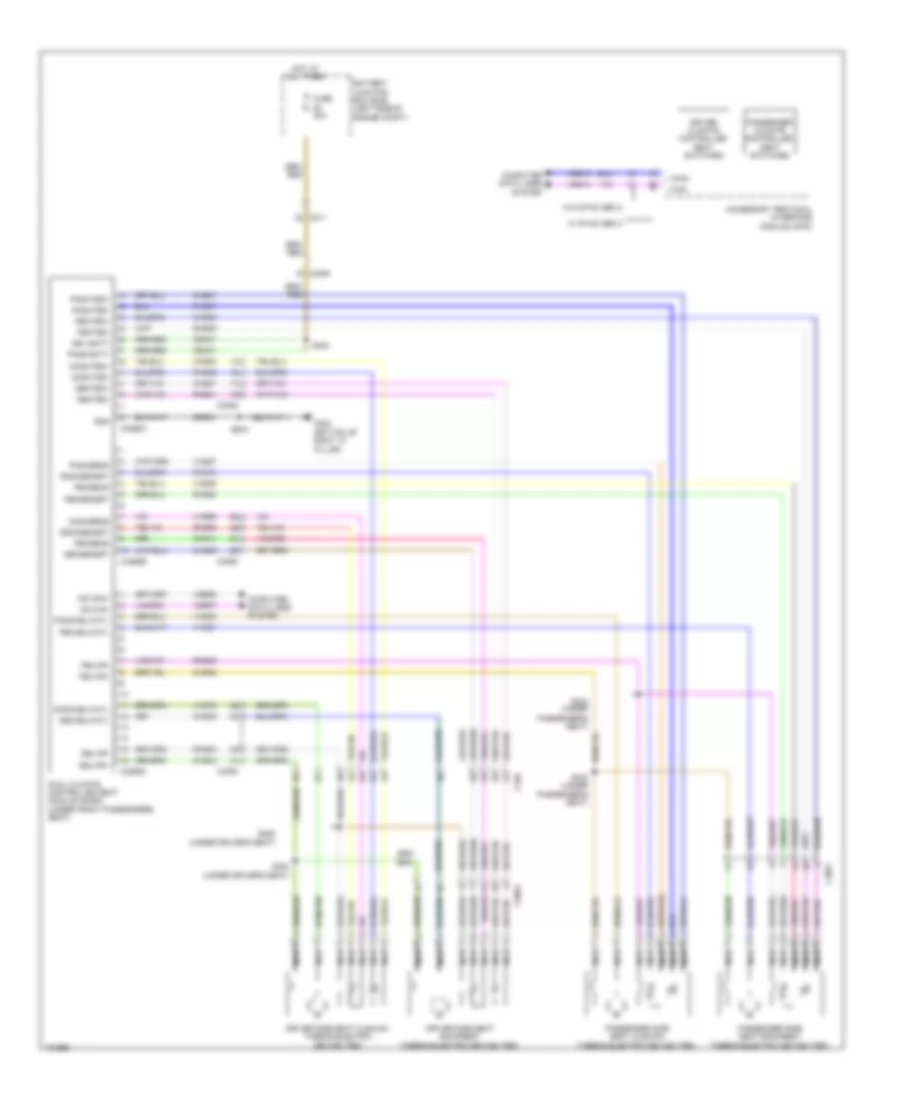 https://portal-diagnostov.com/license.html
Automotive Electricians Portal FZCO
Automotive Electricians Portal FZCO
https://portal-diagnostov.com/license.html
https://portal-diagnostov.com/license.html
Automotive Electricians Portal FZCO
Automotive Electricians Portal FZCOList of elements for Climate Control Seats Wiring Diagram for Ford Flex SEL 2014:
- (bottom of right "c" pillar)
- Accessory protocol interface module (apim)
- Battery junction box (bjb) (left side of engine compt)
- C211
- C3050
- C3051
- C3052
- C3265a
- C3265b
- C3265c
- C340
- Cbx01
- Chs01
- Chs02
- Chs03
- Chs06
- Chs07
- Chs08
- Chs09
- Chs14
- Chs29
- Computer data lines system
- Dbckblwctl
- Dbksensrt
- Dbkted+
- Dbkted-
- Dblwr+
- Dblwr-
- Dcshcblwctl
- Dcshsens
- Dcshsensrt
- Dcshted+
- Dcshted-
- Driver climate controlled seat switches
- Driver side seat backrest thermo-electric device (ted)
- Driver side seat cushion thermo-electric device (ted)
- Drv batt
- Dual climate controlled seat module (dcsm) (under front passenger's seat)
- Fuse 30a
- G300
- Gd904
- Gnd
- Hot at all times
- I can+
- I can-
- Ms can+
- Ms can-
- Nca
- Pass batt
- Passenger climate controlled seat switches
- Passenger side seat backrest thermo-electric device (ted)
- Passenger side seat cushion thermo-electric device (ted)
- Passenger's seat)
- Pbckblwctl
- Pbksens
- Pbksensrt
- Pbkted+
- Pbkted-
- Pblwr+
- Pblwr-
- Pcshcblwctl
- Pcshsens
- Pcshsensrt
- Pcshted+
- Pcshted-
- Rhs01
- Rhs02
- Rhs03
- Rhs05
- Rhs06
- Rhs07
- Rhs08
- Rhs10
- Rhs20
- S322 (under
- S323
- S324 (under
- S325
- S352 (under driver's seat)
- S353 (under driver's seat)
- Vdb06
- Vdb07
- Vdb13
- Vdb14
- Vhs18
- Vhs21
- Vhs23
- Vhs26
- Vhs27
- Vhs36
- W/ sync gen 2
- W/o sync gen 2
Front Heated Seats Wiring Diagram for Ford Flex SEL 2014
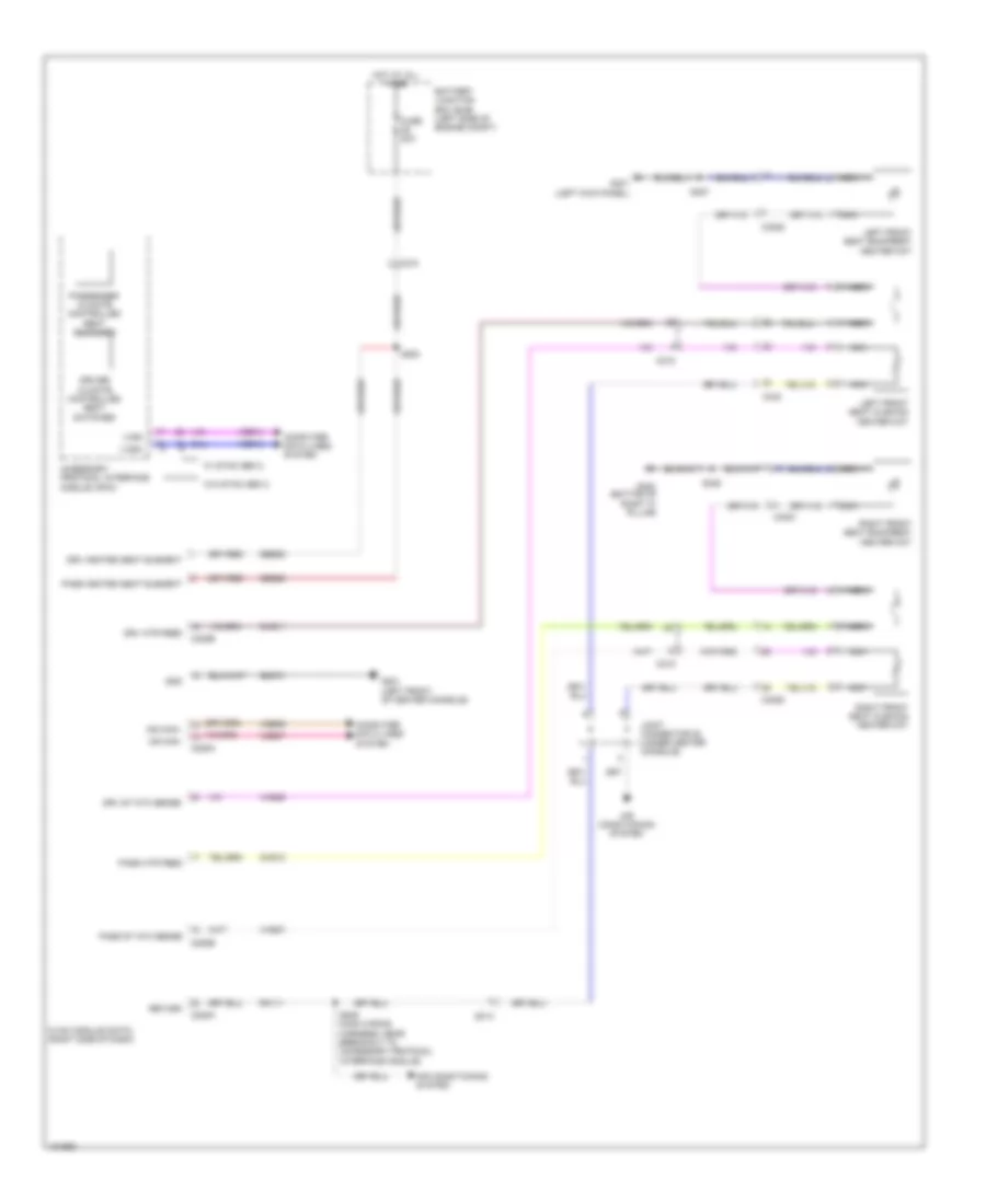 https://portal-diagnostov.com/license.html
Automotive Electricians Portal FZCO
Automotive Electricians Portal FZCO
https://portal-diagnostov.com/license.html
https://portal-diagnostov.com/license.html
Automotive Electricians Portal FZCO
Automotive Electricians Portal FZCOList of elements for Front Heated Seats Wiring Diagram for Ford Flex SEL 2014:
- Accessory protocol interface module (apim)
- Air conditioning system
- Battery junction box (bjb) (left side of engine compt)
- C210
- C215
- C228a
- C228b
- C3050
- C3051
- C3052
- C340
- Chs11
- Chs12
- Computer data lines system
- Driver climate controlled seat switches
- Drv heated seat element
- Drv htr feed
- Drv st ntc sense
- Fuse 20a
- G201 (left front of center console)
- G300 (bottom of right "c" pillar)
- G301 (left kick panel)
- Gd374
- Gnd
- Hot at all times
- Hvac module (datc) (right side of dash)
- I can+
- I can-
- Joint connector 20 (under center console)
- Left front seat backrest heater mat
- Left front seat cushion heater mat
- Ms can+
- Ms can-
- Nca
- Pass heated seat element
- Pass htr feed
- Pass st ntc sense
- Passenger climate controlled seat switches
- Return
- Rh111
- Right front seat backrest heater mat
- Right front seat cushion heater mat
- S200
- S209 (main wiring harness, near breakout to accessory protocol interface module)
- S325
- S357
- Sbb29
- Vdb06
- Vdb07
- Vdb13
- Vdb14
- Vhs26
- Vhs27
- W/ sync gen 2
- W/o sync gen 2
Power Seats Wiring Diagram, 10-Way Driver Seat for Ford Flex SEL 2014
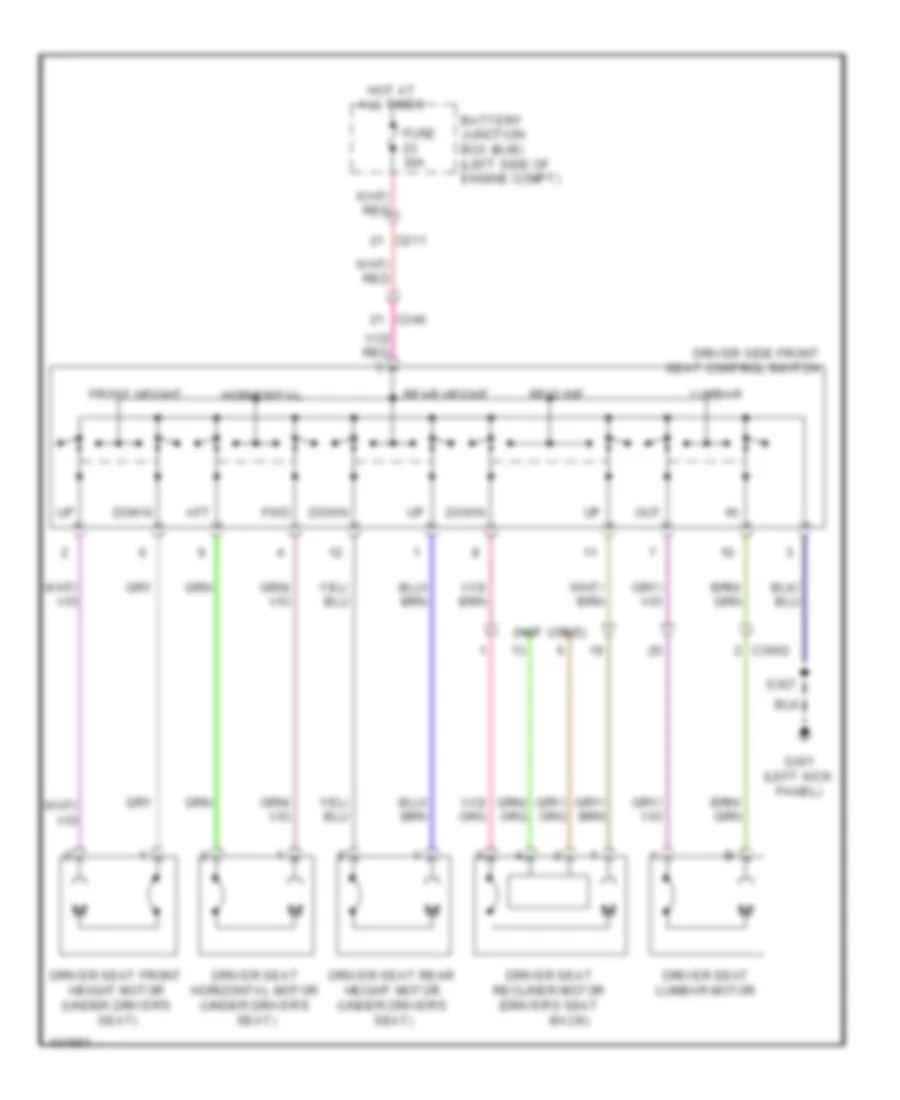 https://portal-diagnostov.com/license.html
Automotive Electricians Portal FZCO
Automotive Electricians Portal FZCO
https://portal-diagnostov.com/license.html
https://portal-diagnostov.com/license.html
Automotive Electricians Portal FZCO
Automotive Electricians Portal FZCOList of elements for Power Seats Wiring Diagram, 10-Way Driver Seat for Ford Flex SEL 2014:
- (not used)
- Aft
- Back)
- Battery junction box (bjb) (left side of engine compt)
- C211
- C3052
- C340
- Down
- Driver seat front height motor (under driver's seat)
- Driver seat horizontal motor (under driver's seat)
- Driver seat lumbar motor
- Driver seat rear height motor (under driver's seat)
- Driver seat recliner motor (driver's seat
- Driver side front seat control switch
- Front height
- Fuse 30a
- Fwd
- G301 (left kick panel)
- Horizontal
- Hot at all times
- Lumbar
- Out
- Rear height
- Recline
- S357
Power Seats Wiring Diagram, 10-Way Passenger Seat for Ford Flex SEL 2014
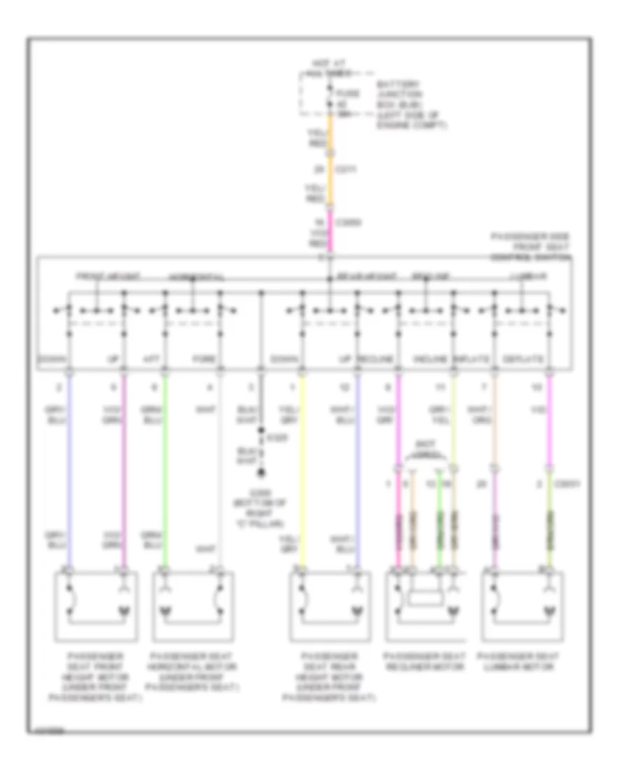 https://portal-diagnostov.com/license.html
Automotive Electricians Portal FZCO
Automotive Electricians Portal FZCO
https://portal-diagnostov.com/license.html
https://portal-diagnostov.com/license.html
Automotive Electricians Portal FZCO
Automotive Electricians Portal FZCOList of elements for Power Seats Wiring Diagram, 10-Way Passenger Seat for Ford Flex SEL 2014:
- (not used)
- Aft
- Battery junction box (bjb) (left side of engine compt)
- C211
- C3050
- C3051
- Deflate
- Down
- Fore
- Front height
- Fuse 30a
- G300 (bottom of right "c" pillar)
- Horizontal
- Hot at all times
- Incline
- Inflate
- Lumbar
- Passenger seat front height motor (under front passenger's seat)
- Passenger seat horizontal motor (under front passenger's seat)
- Passenger seat lumbar motor
- Passenger seat rear height motor (under front passenger's seat)
- Passenger seat recliner motor
- Passenger side front seat control switch
- Rear height
- Recline
- S325
Power Seats Wiring Diagram, 6-Way Driver Seat for Ford Flex SEL 2014
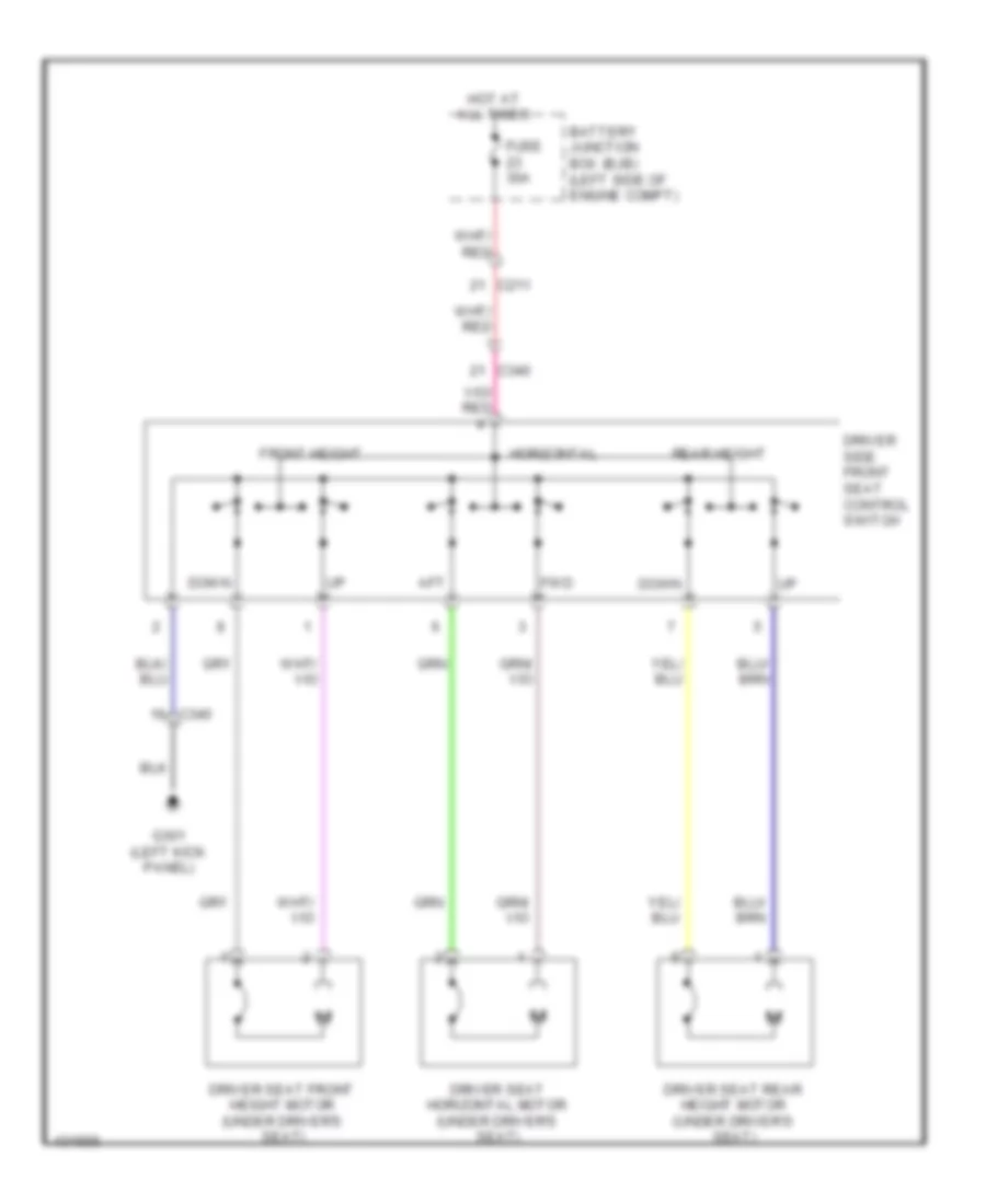 https://portal-diagnostov.com/license.html
Automotive Electricians Portal FZCO
Automotive Electricians Portal FZCO
https://portal-diagnostov.com/license.html
https://portal-diagnostov.com/license.html
Automotive Electricians Portal FZCO
Automotive Electricians Portal FZCOList of elements for Power Seats Wiring Diagram, 6-Way Driver Seat for Ford Flex SEL 2014:
- Aft
- Battery junction box (bjb) (left side of engine compt)
- C211
- C340
- Down
- Driver seat front height motor (under driver's seat)
- Driver seat horizontal motor (under driver's seat)
- Driver seat rear height motor (under driver's seat)
- Driver side front seat control switch
- Front height
- Fuse 30a
- Fwd
- G301 (left kick panel)
- Horizontal
- Hot at all times
- Rear height
Power Seats Wiring Diagram, 6-Way passenger Seat for Ford Flex SEL 2014
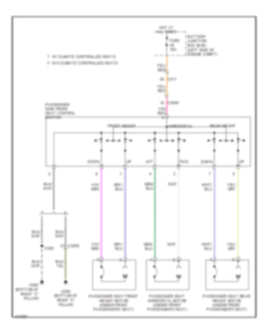 https://portal-diagnostov.com/license.html
Automotive Electricians Portal FZCO
Automotive Electricians Portal FZCO
https://portal-diagnostov.com/license.html
https://portal-diagnostov.com/license.html
Automotive Electricians Portal FZCO
Automotive Electricians Portal FZCOList of elements for Power Seats Wiring Diagram, 6-Way passenger Seat for Ford Flex SEL 2014:
- Aft
- Battery junction box (bjb) (left side of engine compt)
- C211
- C3050
- Down
- Front height
- Fuse 30a
- Fwd
- G300 (bottom of right "c" pillar)
- Horizontal
- Hot at all times
- Passenger seat front height motor (under front passenger's seat)
- Passenger seat horizontal motor (under front passenger's seat)
- Passenger seat rear height motor (under front passenger's seat)
- Passenger side front seat control switch
- Rear height
- S325
- W/ climate controlled seats
- W/o climate controlled seats
Rear Folding Seat Wiring Diagram for Ford Flex SEL 2014
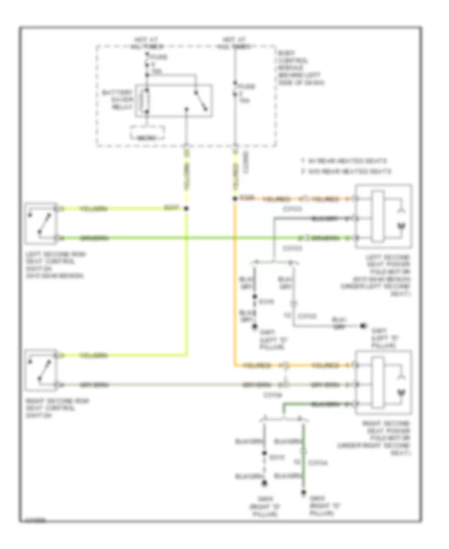 https://portal-diagnostov.com/license.html
Automotive Electricians Portal FZCO
Automotive Electricians Portal FZCO
https://portal-diagnostov.com/license.html
https://portal-diagnostov.com/license.html
Automotive Electricians Portal FZCO
Automotive Electricians Portal FZCOList of elements for Rear Folding Seat Wiring Diagram for Ford Flex SEL 2014:
- Battery saver relay
- Body control module (behind left side of dash)
- C2280d
- C3133
- C3134
- Fuse 10a
- Fuse 15a
- G400 (right "d" pillar)
- G401 (left "d" pillar)
- Hot at all times
- Left second row seat control switch (w/o 60/40 bench)
- Left second seat power fold motor (w/o 60/40 bench) (under left second seat)
- Micro
- Right second row seat control switch
- Right second seat power fold motor (under right second seat)
- S217
- S310
- S315
- S326
- W/ rear heated seats
- W/o rear heated seats
Rear Heated Seats Wiring Diagram for Ford Flex SEL 2014
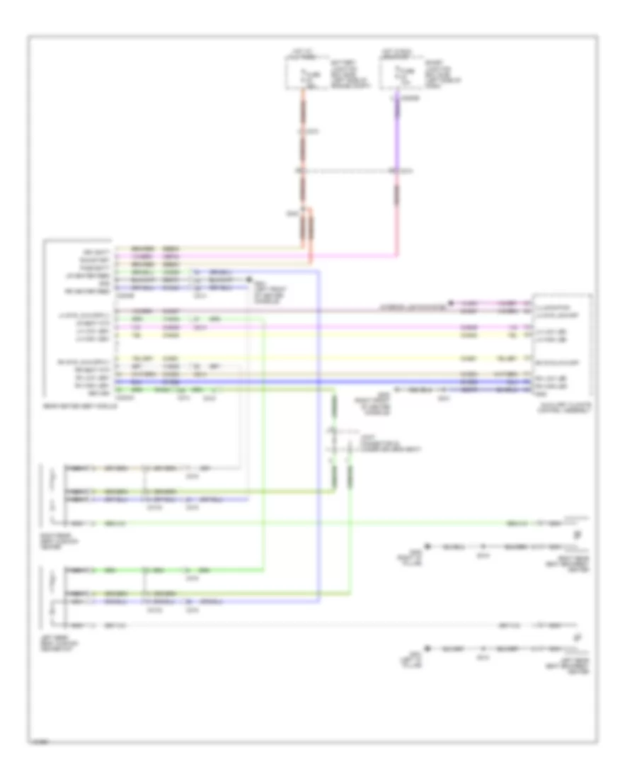 https://portal-diagnostov.com/license.html
Automotive Electricians Portal FZCO
Automotive Electricians Portal FZCO
https://portal-diagnostov.com/license.html
https://portal-diagnostov.com/license.html
Automotive Electricians Portal FZCO
Automotive Electricians Portal FZCOList of elements for Rear Heated Seats Wiring Diagram for Ford Flex SEL 2014:
- Auxiliary climate control assembly
- Battery junction box (bjb) (left side of engine compt)
- C210
- C214
- C215
- C2280b
- C3133
- C3134
- C3304a
- C3304b
- Cbp34
- Chs39
- Chs43
- Chs47
- Chs48
- Chs49
- Chs51
- Chs52
- Chs53
- Drv batt
- Fuse 10a
- Fuse 20a
- G200 (right front of center console)
- G201 (left front of center console)
- G400 (right "d" pillar)
- G401 (left "d" pillar)
- Gd374
- Gd375
- Gnd
- Hot at all times
- Hot in run or start
- Illumination
- Interior lights system
- Joint connector 23 (under driver's seat)
- Left rear seat backrest heater
- Left rear seat cushion heater mat
- Lh high led
- Lh high led+
- Lh low led
- Lh low led+
- Lh sys lo/hi/off
- Lh sys lo/hi/off(v-)
- Lr heater feed
- Lr seat ntc
- Nca
- Pass batt
- Rear heated seat module
- Return
- Rh high led
- Rh high led+
- Rh low led
- Rh low led+
- Rh sys lo/hi/off
- Rh sys lo/hi/off(v-)
- Rhs41
- Right rear seat backrest heater
- Right rear seat cushion heater
- Rr heater feed
- Rr seat ntc
- Run/start
- S310
- S315
- S341
- Sbb30
- Smart junction box (sjb) (left side of dash)
- Vhs42
- Vhs45
- Vln04
Third Row Folding Seat Wiring Diagram for Ford Flex SEL 2014
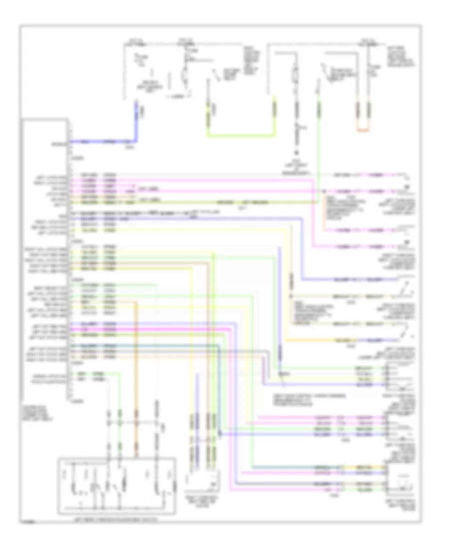 https://portal-diagnostov.com/license.html
Automotive Electricians Portal FZCO
Automotive Electricians Portal FZCO
https://portal-diagnostov.com/license.html
https://portal-diagnostov.com/license.html
Automotive Electricians Portal FZCO
Automotive Electricians Portal FZCOList of elements for Third Row Folding Seat Wiring Diagram for Ford Flex SEL 2014:
- (left "d" pillar) g401
- (not used)
- (seat back control wiring harness, near breakout to power fold module)
- 3rd row seat enable (fet)
- Batt+
- Battery junction box (bjb) (left side of engine compt)
- Battery saver relay
- Body control module (behind left side of dash)
- C211
- C2280c
- C2280f
- C408
- C422
- C423
- C4250a
- C4250b
- C4250c
- C4250d
- C4250e
- Cbb22
- Cps48
- Cpsa1
- Cpsa2
- Cpsa3
- Cpsa5
- Cpsa6
- Cpsa8
- Cpsa9
- Cpsb0
- Cpsb1
- Cpsb2
- Cpsb3
- Cpsb4
- Cpsb6
- Cpsb7
- Cpsb9
- Cpsc0
- Enable
- Fold
- Fold/tailgate sw
- Fuse 10a
- Fuse 30a
- G101 (left front of engine compt)
- Gd349
- Gnd
- Hot at all times
- Left
- Left hall rec pos
- Left hall stow pos
- Left latch pos
- Left latch sw
- Left mot rec pos
- Left mot stow pos
- Left rear third row folding seat switch
- Left third row folding seat motor (left side of third row seat)
- Left third row seat latch motor (under left third row seat)
- Left third row seat latch switch (under left third row seat)
- Left third row seat recline motor
- Logic
- Lpsa4
- Lpsa7
- Lpsb5
- Lpsb8
- Ms can+
- Ms can-
- Normal
- Normal stow sw
- Power fold module (pfm) (under third row left seat)
- Return latch sw
- Return sw
- Right
- Right hall rec pos
- Right hall stow pos
- Right latch pos
- Right latch sw
- Right mot rec pos
- Right mot stow pos
- Right third row folding seat motor (right side of third row seat)
- Right third row seat latch motor (under right third row seat)
- Right third row seat latch switch (under right third row seat)
- Right third row seat recline motor
- Rpsa4
- Rpsa7
- Rpsb0
- Rpsb2
- Rpsb5
- S143
- S402 (seat back control wiring harness, near breakout to power fold module)
- S403 (seat back control wiring harness, near breakout to power fold module)
- S404
- S419
- Seat select sw
- Stow
- Tail
- Third row power seat relay
- Vdb06
- Vdb07
POWER TOP/SUNROOF
Power Top/Sunroof Wiring Diagram for Ford Flex SEL 2014
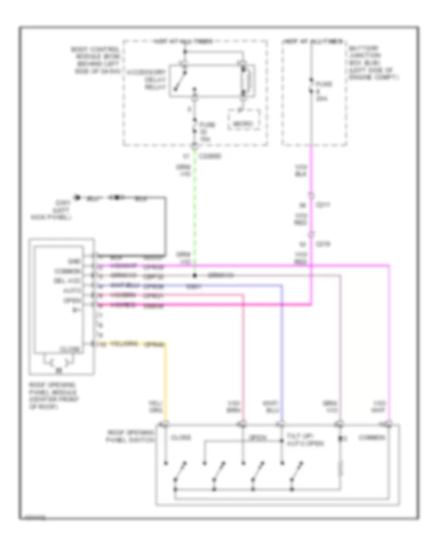 https://portal-diagnostov.com/license.html
Automotive Electricians Portal FZCO
Automotive Electricians Portal FZCO
https://portal-diagnostov.com/license.html
https://portal-diagnostov.com/license.html
Automotive Electricians Portal FZCO
Automotive Electricians Portal FZCOList of elements for Power Top/Sunroof Wiring Diagram for Ford Flex SEL 2014:
- Accessory delay relay
- Auto
- Battery junction box (bjb) (left side of engine compt)
- Body control module (bcm) (behind left side of dash)
- C211
- C219
- C2280d
- Cbp32
- Close
- Common
- Cpr31
- Cpr38
- Cpr39
- Cpr40
- Del acc
- Fuse 15a
- Fuse 20a
- G301 (left kick panel)
- Gd233
- Gnd
- Hot at all times
- Micro
- Open
- Roof opening panel module (center front of roof)
- Roof opening panel switch
- S900
- S901
- Sbb08
- Tilt up/ auto open
POWER WINDOWS
Power Windows Wiring Diagram (1 of 2) for Ford Flex SEL 2014
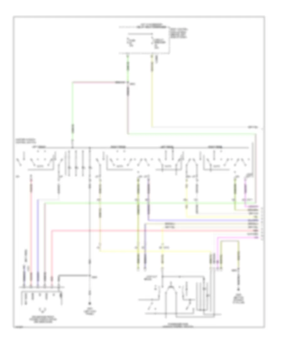 https://portal-diagnostov.com/license.html
Automotive Electricians Portal FZCO
Automotive Electricians Portal FZCO
https://portal-diagnostov.com/license.html
https://portal-diagnostov.com/license.html
Automotive Electricians Portal FZCO
Automotive Electricians Portal FZCOList of elements for Power Windows Wiring Diagram (1 of 2) for Ford Flex SEL 2014:
- (not used)
- Auto
- Body control module (bcm) (behind left side of dash)
- C2280d
- C311
- C312
- Circuit breaker 30a
- Down
- Driver side front power window motor (driver's door)
- Fuse 15a
- G300 (bottom of right "c" pillar)
- G301 (left kick panel)
- Gnd
- Hot w/accessory delay relay energized
- Left front
- Left rear
- Lock out
- Lock out pwr
- Master window control switch
- Not used
- Passenger side window control switch
- Red
- Right front
- Right rear
- S500
- S503
- S600
- Vpwr
Power Windows Wiring Diagram (2 of 2) for Ford Flex SEL 2014
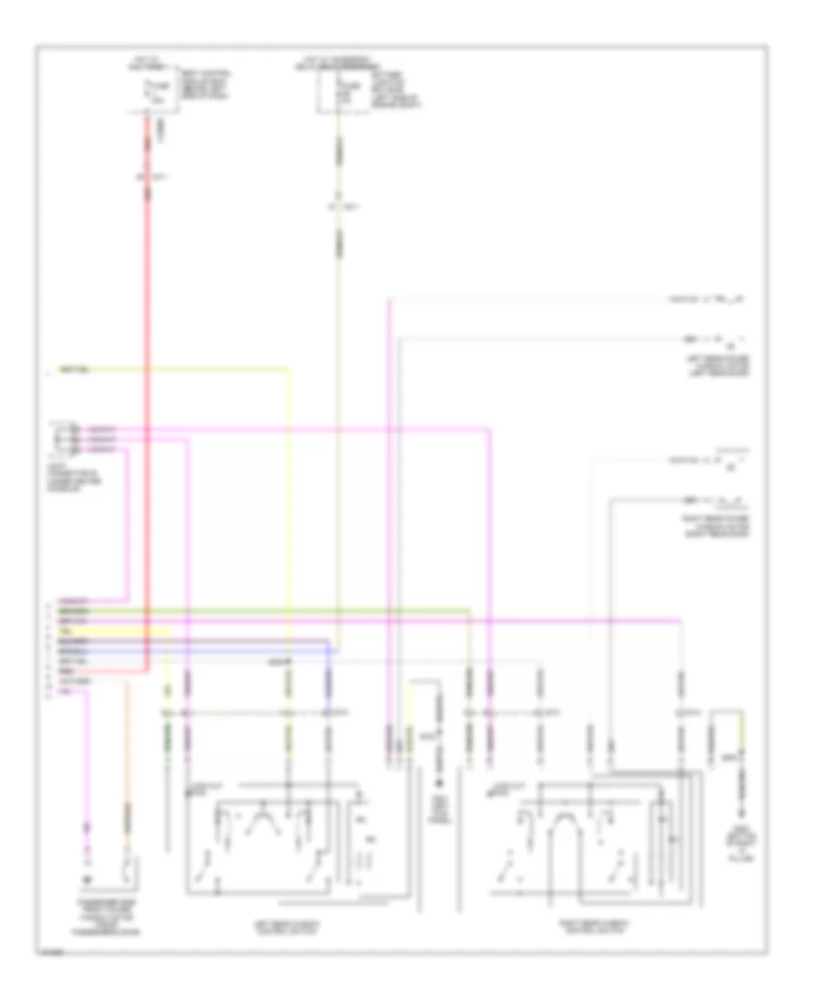 https://portal-diagnostov.com/license.html
Automotive Electricians Portal FZCO
Automotive Electricians Portal FZCO
https://portal-diagnostov.com/license.html
https://portal-diagnostov.com/license.html
Automotive Electricians Portal FZCO
Automotive Electricians Portal FZCOList of elements for Power Windows Wiring Diagram (2 of 2) for Ford Flex SEL 2014:
- Battery junction box (bjb) (left side of engine compt)
- Body control module (bcm) (behind left side of dash)
- C211
- C2280b
- C311
- C313
- C314
- Fuse 30a
- Fuse 5a
- G300 (bottom of right "c" pillar)
- G301 (left kick panel)
- Hot at all times
- Hot w/ accessory delay relay energized
- Joint connector 20 (under center console)
- Left rear power window motor (left rear door)
- Left rear window control switch
- Lock out pwr
- Passenger side front power window motor (front passenger's door)
- Red
- Right rear power window motor (right rear door)
- Right rear window control switch
- S304
- S700
- S800
RADIO
Radio Wiring Diagram, with Sony (1 of 2) for Ford Flex SEL 2014
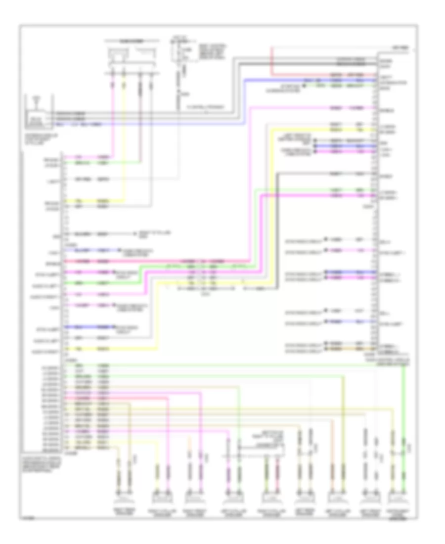 https://portal-diagnostov.com/license.html
Automotive Electricians Portal FZCO
Automotive Electricians Portal FZCO
https://portal-diagnostov.com/license.html
https://portal-diagnostov.com/license.html
Automotive Electricians Portal FZCO
Automotive Electricians Portal FZCOList of elements for Radio Wiring Diagram, with Sony (1 of 2) for Ford Flex SEL 2014:
- (bottom of right "c" pillar) joint connector 19
- (left front of center console) g201
- (right "d" pillar) g400
- Am/fm
- Antenna module (top of right "d" pillar)
- Antenna pwr
- Audio control module (center of dash)
- Audio digital signal processing module (behind right rear quarterpanel)
- Audio in left +
- Audio in left -
- Audio in right +
- Audio in right -
- Body control module (bcm) (behind left side of dash)
- C212
- C240a
- C240b
- C2880d
- C311
- C312
- C313
- C314
- C4326a
- C4326b
- C4326c
- Ce336
- Coaxial cable
- Computer data lines system
- Dme17
- Enable
- Fc spkr +
- Fc spkr -
- Fuse 20a
- Gd351
- Gd374
- Gnd
- Hot at all times
- I can +
- I can -
- Instrument panel speaker
- Left a pillar speaker
- Left d pillar speaker
- Left front speaker
- Left rear speaker
- Lf spkr +
- Lf spkr -
- Lr spkr +
- Lr spkr -
- Lr sub +
- Lr sub -
- Nca
- Rc spkr +
- Rc spkr -
- Rf spkr +
- Rf spkr -
- Right a pillar speaker
- Right d pillar speaker
- Right front speaker
- Right rear speaker
- Rme01
- Rme02
- Rme06
- Rme07
- Rme08
- Rme09
- Rme10
- Rme11
- Rme12
- Rme17
- Rme18
- Rme30
- Rme52
- Rme53
- Rme80
- Rr spkr +
- Rr spkr -
- Rr sub +
- Rr sub -
- S400
- Sbp05
- Sbp29
- Sdars
- Sdl-h
- Sdl-l
- Shield
- Smcs
- Sme23
- Solid state
- Starting/ charging system
- Stereo l +
- Stereo l -
- Stereo r +
- Stereo r -
- Subwoofer
- Sync alert +
- Sync alert -
- Sync alert+
- Sync alert-
- Sync radio circuit
- V batt
- Vbatt
- Vdb13
- Vdb14
- Vme01
- Vme02
- Vme06
- Vme07
- Vme08
- Vme09
- Vme10
- Vme11
- Vme12
- Vme17
- Vme18
- Vme30
- Vme43
- Vme52
- Vme53
- Vme80
- Vme90
- Vme91
- W/ satellite radio
Radio Wiring Diagram, with Sony (2 of 2) for Ford Flex SEL 2014
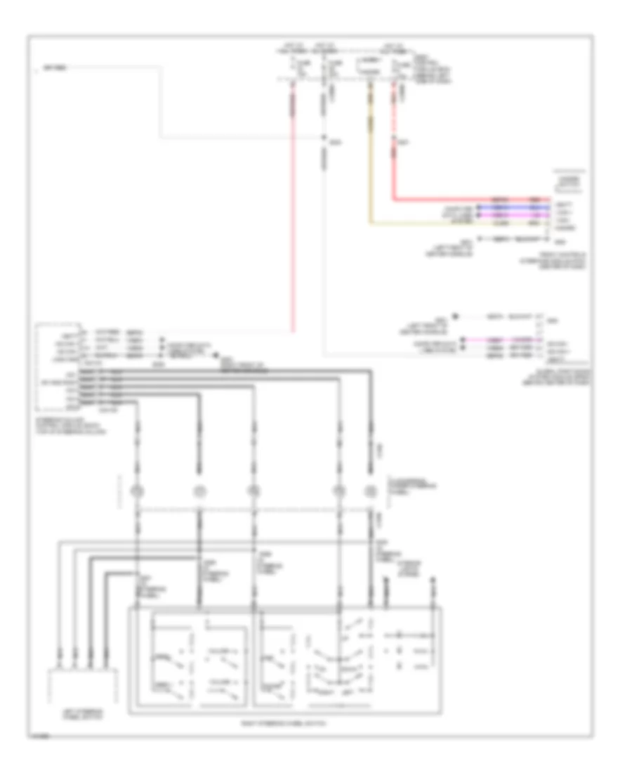 https://portal-diagnostov.com/license.html
Automotive Electricians Portal FZCO
Automotive Electricians Portal FZCO
https://portal-diagnostov.com/license.html
https://portal-diagnostov.com/license.html
Automotive Electricians Portal FZCO
Automotive Electricians Portal FZCOList of elements for Radio Wiring Diagram, with Sony (2 of 2) for Ford Flex SEL 2014:
- (behind left side of dash)
- (in steering wheel)
- Body control module (bcm)
- C218b
- C218c
- C2280a
- C2280b
- C2414d
- Clockspring (under steering wheel)
- Cls32
- Computer data lines system
- Down
- Front controls interface module (fcim) (center of dash)
- Fuse 10a
- Fuse 15a
- Fuse 20a
- G200 (right front of center console)
- G201 (left front of center console)
- Gd374
- Gd375
- Global positioning system module (gpsm) (behind center of dash)
- Gnd
- Hazard
- Hazard switch
- Hot at all times
- Hs can +
- Hs can -
- I can +
- I can -
- Interior lights system
- Left
- Left steering wheel switch
- Logic gnd c2414a
- Micro
- Ms can +
- Ms can -
- Nca
- Nca a/d 1 nca sw gnd right nca a/d 3 nca a/d 4 nca a/d 2
- Phone
- Ptt
- Red
- Right
- Right steering wheel switch
- S201
- S203
- S206
- S220 (in steering wheel)
- S221 (in steering wheel) nca
- S295
- S296
- Sbp09
- Sbp23
- Sbp29
- Seek +
- Seek -
- Steering column control module (sccm) (top of steering column)
- Vbatt
- Vdb04
- Vdb05
- Vdb06
- Vdb07
- Vdb13
- Vdb14
- Volume +
- Volume -
Radio Wiring Diagram, without Sony (1 of 2) for Ford Flex SEL 2014
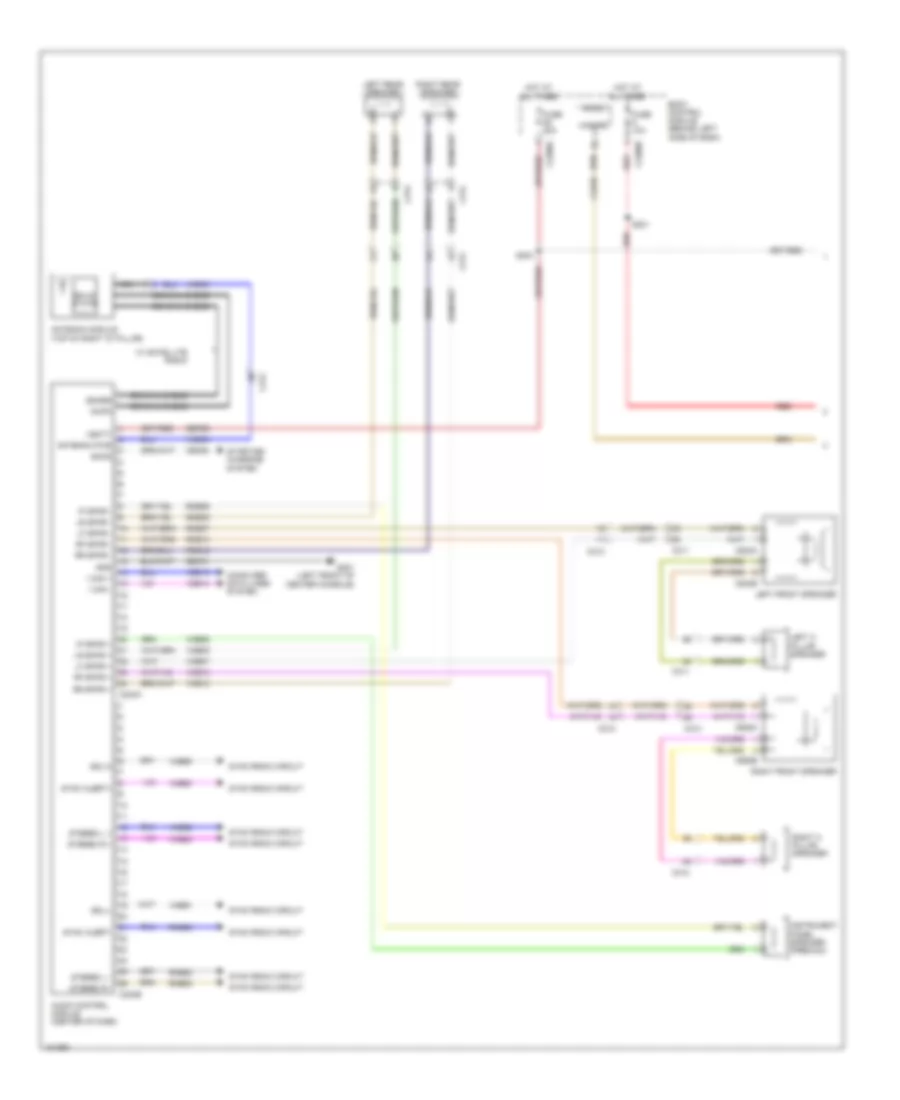 https://portal-diagnostov.com/license.html
Automotive Electricians Portal FZCO
Automotive Electricians Portal FZCO
https://portal-diagnostov.com/license.html
https://portal-diagnostov.com/license.html
Automotive Electricians Portal FZCO
Automotive Electricians Portal FZCOList of elements for Radio Wiring Diagram, without Sony (1 of 2) for Ford Flex SEL 2014:
- Am/fm
- Antenna module (top of right "d" pillar)
- Antenna pwr
- Audio control module (center of dash)
- Body control module (behind left side of dash)
- C212
- C2280a
- C2280b
- C240a
- C240b
- C311
- C312
- C313
- C314
- C523a
- C523b
- C652a
- C652b
- Ce336
- Cls32
- Coaxial cable
- Computer data lines system
- Fuse 10a
- Fuse 20a
- G201 (left front of center console)
- Gd374
- Gnd
- Hazard
- Hot at all times
- I can +
- I can -
- Instrument panel speaker (premium)
- Ip spkr +
- Ip spkr -
- Left a pillar speaker
- Left front speaker
- Left rear speaker
- Lf spkr +
- Lf spkr -
- Lr spkr +
- Lr spkr -
- Micro
- Nca
- Red
- Rf spkr +
- Rf spkr -
- Right a pillar speaker
- Right front speaker
- Right rear speaker
- Rme06
- Rme07
- Rme09
- Rme10
- Rme12
- Rme52
- Rme53
- Rme80
- Rr spkr +
- Rr spkr -
- S201
- S203
- Sbp29
- Sdars
- Sdl-h
- Sdl-l
- Smcs
- Solid state
- Starting/ charging system
- Stereo l +
- Stereo l -
- Stereo r +
- Stereo r -
- Sync alert+
- Sync alert-
- Sync radio circuit
- Vbatt
- Vdb13
- Vdb14
- Vme06
- Vme07
- Vme09
- Vme10
- Vme12
- Vme43
- Vme52
- Vme53
- Vme80
- Vme90
- Vme91
- W/ satellite radio
Radio Wiring Diagram, without Sony (2 of 2) for Ford Flex SEL 2014
 https://portal-diagnostov.com/license.html
Automotive Electricians Portal FZCO
Automotive Electricians Portal FZCO
https://portal-diagnostov.com/license.html
https://portal-diagnostov.com/license.html
Automotive Electricians Portal FZCO
Automotive Electricians Portal FZCOList of elements for Radio Wiring Diagram, without Sony (2 of 2) for Ford Flex SEL 2014:
- (behind left side of dash)
- (in steering wheel)
- Body control module (bcm)
- C218b
- C218c
- C2280a
- C2414d
- Clockspring (under steering wheel)
- Cls32
- Computer data lines system
- Down
- Front controls interface module (fcim) (center of dash)
- Fuse 15a
- G200 (right front of center console)
- G201 (left front of center console)
- Gd374
- Gd375
- Global positioning system module (gpsm) (behind center of dash)
- Gnd
- Hazard
- Hazard switch
- Hot at all times
- Hs can +
- Hs can -
- I can +
- I can -
- Interior lights system
- Left
- Left steering wheel switch
- Logic gnd c2414a
- Ms can +
- Ms can -
- Nca
- Nca a/d 1 nca sw gnd right nca a/d 3 nca a/d 4 nca a/d 2
- Phone
- Ptt
- Red
- Right
- Right steering wheel switch
- S206
- S220 (in steering wheel)
- S221 (in steering wheel) nca
- S295
- S296
- Sbp09
- Sbp23
- Sbp29
- Seek +
- Seek -
- Steering column control module (sccm) (top of steering column)
- Vbatt
- Vdb04
- Vdb05
- Vdb06
- Vdb07
- Vdb13
- Vdb14
- Volume +
- Volume -
SYNC Radio Wiring Diagram, with SYNC GEN 1 (1 of 2) for Ford Flex SEL 2014
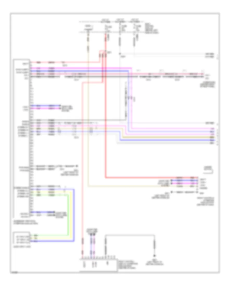 https://portal-diagnostov.com/license.html
Automotive Electricians Portal FZCO
Automotive Electricians Portal FZCO
https://portal-diagnostov.com/license.html
https://portal-diagnostov.com/license.html
Automotive Electricians Portal FZCO
Automotive Electricians Portal FZCOList of elements for SYNC Radio Wiring Diagram, with SYNC GEN 1 (1 of 2) for Ford Flex SEL 2014:
- (center of dash)
- Accessory protocol interface module (apim)
- Audio input jack
- Body control module (behind left side of dash)
- C212
- C214
- C219
- C2280a
- C2280b
- Cls32
- Computer data lines system
- Dme45
- Dme52
- Dme80
- Dmm23
- Front control/ display interface module (fdim) (center of dash)
- Front controls interface module (fcim)
- Fuse 10a
- Fuse 15a
- Fuse 20a
- G201 (left front of center console)
- Gd374
- Gnd
- Hazard
- Hazard switch
- Hot at all times
- Hs can +
- Hs can -
- I can +
- I can -
- Mic +
- Mic -
- Micro
- Microphone (center front of roof panel)
- Nca
- Pwr gnd
- Pwr gnd2
- Red
- Rme45
- Rme52
- Rme53
- Rme80
- S201
- S203
- Sbp09
- Shield
- St input 2l+
- St input 2r+
- St input lr-
- Stereo 2l+
- Stereo 2r+
- Stereo l +
- Stereo l -
- Stereo lr-
- Stereo r +
- Stereo r -
- Stereo shield
- Sync alert+
- Sync alert-
- Vbatt
- Vdb04
- Vdb05
- Vdb13
- Vdb14
- Vme45
- Vme46
- Vme52
- Vme53
- Vme80
- Vmm23
SYNC Radio Wiring Diagram, with SYNC GEN 1 (2 of 2) for Ford Flex SEL 2014
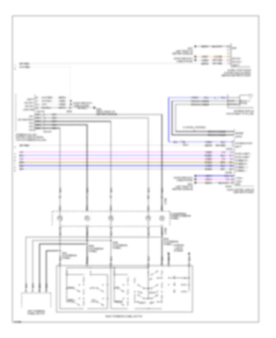 https://portal-diagnostov.com/license.html
Automotive Electricians Portal FZCO
Automotive Electricians Portal FZCO
https://portal-diagnostov.com/license.html
https://portal-diagnostov.com/license.html
Automotive Electricians Portal FZCO
Automotive Electricians Portal FZCOList of elements for SYNC Radio Wiring Diagram, with SYNC GEN 1 (2 of 2) for Ford Flex SEL 2014:
- Am/fm
- Antenna module (top of right "d" pillar)
- Antenna pwr
- Audio control module (center of dash)
- Batt
- C212
- C218b
- C218c
- C240a
- C240b
- C2414a
- C2414d
- Clockspring (under steering wheel)
- Coaxial cable
- Computer data lines system
- Down
- G200 (right front of center console)
- G201 (left front of center console)
- Gd374
- Gd375
- Global positioning system module (gpsm) (behind center of dash)
- Gnd
- Hs can +
- Hs can -
- I can +
- I can -
- Interior lights system
- Left
- Left steering wheel switch
- Logic gnd
- Ms can +
- Ms can -
- Nca
- Nca a/d 1 nca sw gnd right nca a/d 3 nca a/d 4 nca a/d 2
- Phone
- Ptt
- Right
- Right steering wheel switch
- Rme52
- Rme53
- Rme80
- S206
- S220 (in steering wheel)
- S221 (in steering wheel)
- S295 (in steering wheel)
- S296 (in steering wheel)
- Sat/nav
- Sbp23
- Sbp29
- Sdars
- Seek +
- Seek -
- Solid state
- Steering column control module (sccm) (top of steering column)
- Stereo l +
- Stereo l -
- Stereo r +
- Stereo r -
- Sync alert+
- Sync alert-
- Vbatt
- Vdb04
- Vdb05
- Vdb06
- Vdb07
- Vdb13
- Vdb14
- Vme43
- Vme52
- Vme53
- Vme80
- Vol +
- Vol -
- W/ satellite radio
SYNC Radio Wiring Diagram, with SYNC GEN 2 (1 of 2) for Ford Flex SEL 2014
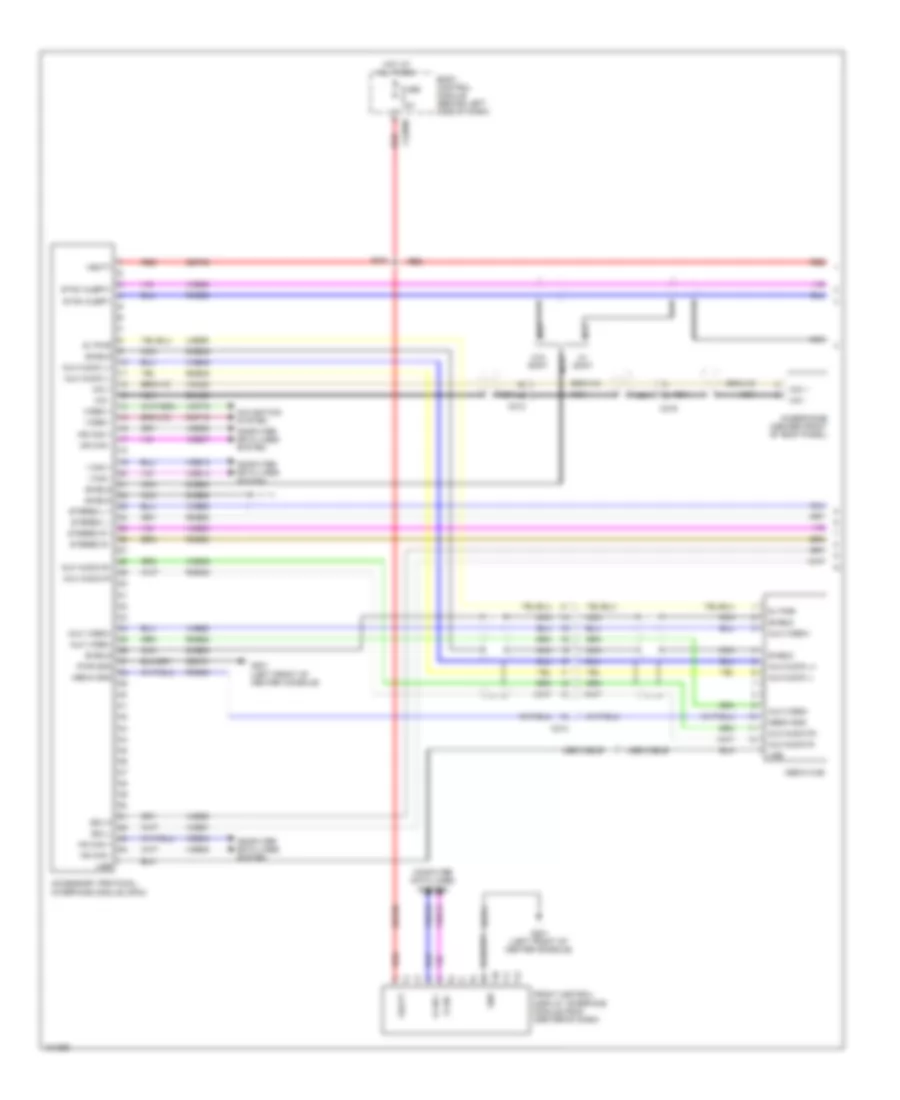 https://portal-diagnostov.com/license.html
Automotive Electricians Portal FZCO
Automotive Electricians Portal FZCO
https://portal-diagnostov.com/license.html
https://portal-diagnostov.com/license.html
Automotive Electricians Portal FZCO
Automotive Electricians Portal FZCOList of elements for SYNC Radio Wiring Diagram, with SYNC GEN 2 (1 of 2) for Ford Flex SEL 2014:
- 5v pwr
- Accessory protocol interface module (apim)
- Aux audio l+
- Aux audio l-
- Aux audio r+
- Aux audio r-
- Aux video+
- Aux video-
- Body control module (behind left side of dash)
- C212
- C214
- C219
- C2280b
- Computer data lines system
- Dme45
- Dme52
- Dme80
- Dme88
- Dmm23
- Front control/ display interface module (fdim) (center of dash)
- Fuse 10a
- G201 (left front of center console)
- Gd374
- Gnd
- Hot at all times
- Hs can +
- Hs can -
- I can +
- I can -
- Lme89
- Media gnd
- Media hub
- Mic +
- Mic -
- Microphone (center front of roof panel)
- Ms can +
- Ms can -
- Navigation system
- Nca
- Pwr gnd
- Red
- Rme45
- Rme46
- Rme52
- Rme53
- Rme80
- Rme88
- Rme89
- Rmp19
- S201
- Sbp09
- Sdl-h
- Sdl-l
- Shield
- Stereo l +
- Stereo l -
- Stereo r +
- Stereo r -
- Sync alert+
- Sync alert-
- Usb
- Usb cable
- Vbatt
- Vdb04
- Vdb05
- Vdb06
- Vdb07
- Vdb13
- Vdb14
- Video +
- Video -
- Vme45
- Vme46
- Vme52
- Vme53
- Vme80
- Vme88
- Vme90
- Vme91
- Vmm23
- Vmp19
- W/ sony
- W/o sony
SYNC Radio Wiring Diagram, with SYNC GEN 2 (2 of 2) for Ford Flex SEL 2014
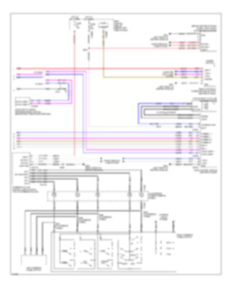 https://portal-diagnostov.com/license.html
Automotive Electricians Portal FZCO
Automotive Electricians Portal FZCO
https://portal-diagnostov.com/license.html
https://portal-diagnostov.com/license.html
Automotive Electricians Portal FZCO
Automotive Electricians Portal FZCOList of elements for SYNC Radio Wiring Diagram, with SYNC GEN 2 (2 of 2) for Ford Flex SEL 2014:
- (behind center of dash)
- (top of right "d" pillar) antenna module
- A/d 1
- A/d 2
- A/d 3
- A/d 4
- Am/fm
- Antenna pwr
- Audio control module (center of dash)
- Audio digital signal processing(dsp) module (behind right rear quarterpanel)
- Batt
- Body control module (behind left side of dash)
- C212
- C218b
- C218c
- C2280a
- C2280b
- C240a
- C240b
- C2414a
- C2414d
- C4326a
- Clockspring (under steering wheel)
- Cls32
- Coaxial cable
- Computer data lines system
- Down
- Front controls interface module (fcim) (center of dash)
- Fuse 15a
- Fuse 20a
- G200 (right front of center console)
- G201 (left front of center console)
- Gd374
- Gd375
- Global positioning system module (gpsm)
- Gnd
- Hazard
- Hazard switch
- Hot at all times
- Hs can +
- Hs can -
- I can +
- I can -
- Interior lights system
- Left
- Left steering wheel switch
- Logic gnd
- Micro
- Ms can +
- Ms can -
- Nca
- Phone
- Ptt
- Red
- Right
- Right steering wheel switch
- Rme52
- Rme53
- Rme80
- S203
- S206
- S220 (in steering wheel)
- S221 (in steering wheel) nca
- S295 (in steering wheel)
- S296 (in steering wheel)
- Sat/nav
- Sbp09
- Sbp23
- Sbp29
- Sdars
- Sdl -l
- Sdl-h
- Seek +
- Seek -
- State solid
- Steering column control module (sccm) (top of steering column)
- Stereo l +
- Stereo l -
- Stereo r +
- Stereo r -
- Sw gnd right
- Sync alert +
- Sync alert -
- Sync alert+
- Sync alert-
- Vbatt
- Vdb04
- Vdb05
- Vdb06
- Vdb07
- Vdb13
- Vdb14
- Vme43
- Vme52
- Vme53
- Vme80
- Vme90
- Vme91
- Vol +
- Vol -
- W/ satellite radio
- W/ sony
- W/o sony
SHIFT INTERLOCK
Shift Interlock Wiring Diagram for Ford Flex SEL 2014
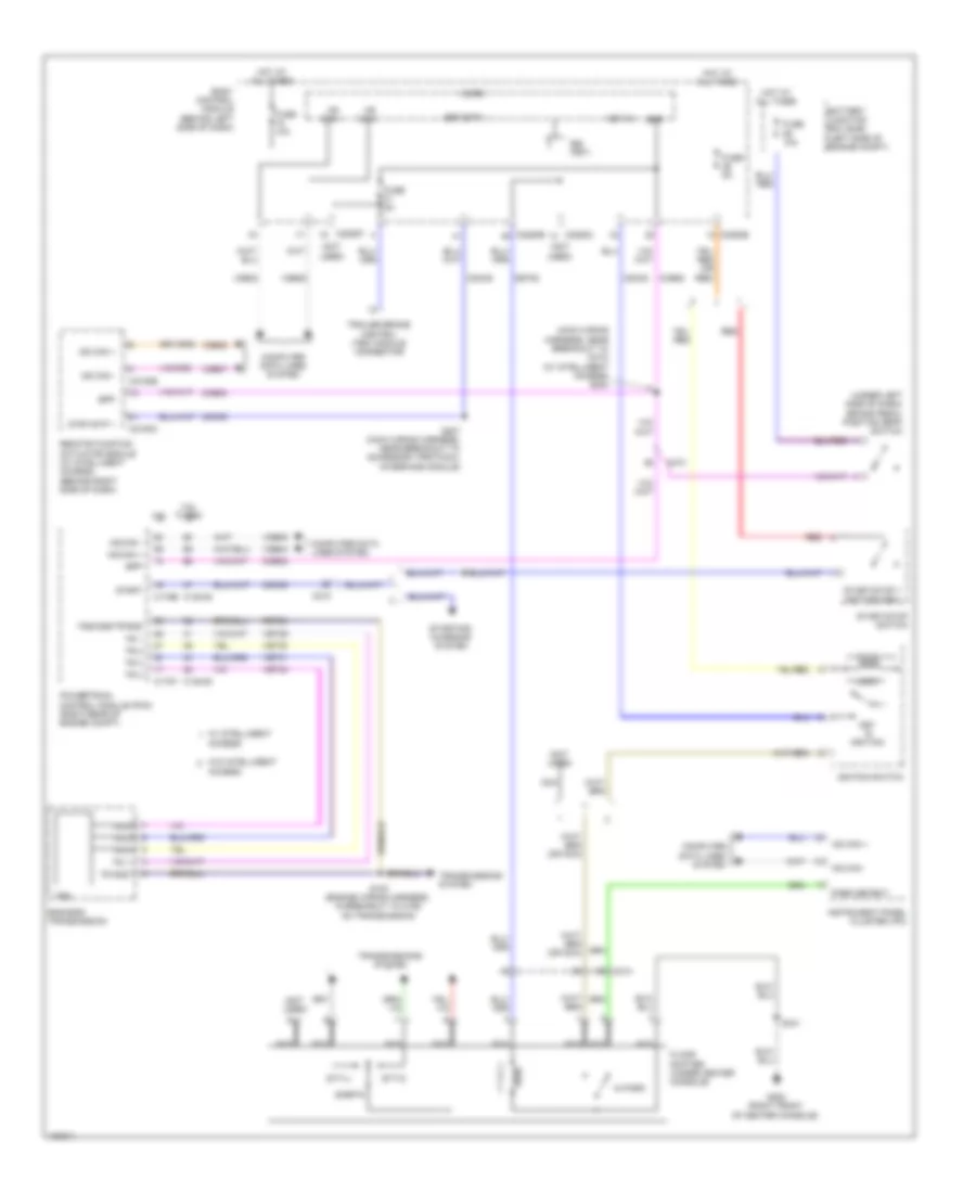 https://portal-diagnostov.com/license.html
Automotive Electricians Portal FZCO
Automotive Electricians Portal FZCO
https://portal-diagnostov.com/license.html
https://portal-diagnostov.com/license.html
Automotive Electricians Portal FZCO
Automotive Electricians Portal FZCOList of elements for Shift Interlock Wiring Diagram for Ford Flex SEL 2014:
- (main wiring harness, near breakout to c210) (w/ intelligent access) s204
- (not used)
- (under left side of dash) brake pedal position (bpp) switch
- 3.5l
- 3.5l turbo
- 6f50/6f55 transmission
- Access
- Battery junction box (bjb) (left side of engine compt)
- Body control module (behind left side of dash)
- Bpp
- Bsi (fet)
- C1381b
- C1381e
- C175b
- C175t
- C210
- C214
- C2153c
- C2153e
- C2280b
- C2280c
- C2280f
- Ccb08
- Cdc30
- Cdc35
- Cet53
- Computer data lines system
- Floor shifter (under center console)
- Fuse 10a
- Fuse 5a
- G200 (right front of center console)
- Hot at all times
- Hs can +
- Hs can -
- Ignition switch
- In park
- Instrument panel cluster (ipc)
- Key in
- Key in ignition
- Lock
- Micro
- Ms can +
- Ms can -
- Nca
- Park detect
- Powertrain control module (pcm) (right rear of engine compt)
- Red
- Remote function actuator module (w/ intelligent access) (behind right side of dash)
- Ret24
- S100 (engine wiring harness, in breakout to c168 on transmission)
- S207 (main wiring harness, near breakout to accessory protocol interface module)
- S341
- Sigrtn
- Srt/stp 1
- Start
- Start/stop 1 (active high)
- Start/stop switch
- Starting/ charging system
- Strt/stp 1
- Stt-d
- Stt-u
- Tr 1
- Tr 2
- Tr 3
- Tr 4
- Tr gnd
- Trailer brake control (tbc) module connector
- Transmissions system
- Trs
- Tss/oss/tr gnd
- Vdb04
- Vdb05
- Vdb06
- Vdb07
- Vet29
- Vet30
- Vet31
- Vet32
- W/ intelligent
- W/o intelligent
STARTING/CHARGING
Charging Wiring Diagram for Ford Flex SEL 2014
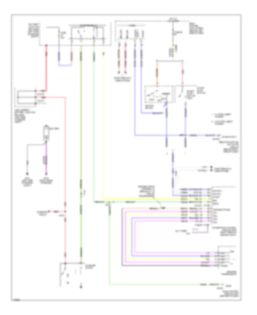 https://portal-diagnostov.com/license.html
Automotive Electricians Portal FZCO
Automotive Electricians Portal FZCO
https://portal-diagnostov.com/license.html
https://portal-diagnostov.com/license.html
Automotive Electricians Portal FZCO
Automotive Electricians Portal FZCOList of elements for Charging Wiring Diagram for Ford Flex SEL 2014:
- (engine wiring harness, in breakout to c168 on transmission)
- 3.5l
- 3.5l turbo
- 6f50/6f55 transmission
- Acc
- Audio control module (acm) (center of dash)
- Battery
- Battery junction box (bjb) (left side of engine compt)
- Body control module (bcm) (behind left side of dash)
- C144
- C1617c
- C1617d
- C175b c1381b
- C175t c1381e
- C210
- C2153c
- C2280b
- C240a
- Cdc12
- Cdc35
- Ce336
- Charging circuit
- Computer data lines system
- Fuse 26 5a
- Fuse 30a
- G103 (left side of engine compt)
- G104 (right rear of engine)
- High current battery junction box (bjb) (left side of engine compt)
- Hot at all times
- Hs can +
- Hs can -
- Ignition switch
- Lock
- Micro
- Ms can +
- Ms can -
- Off
- Powertrain control module (pcm) (right rear of engine compt)
- Red
- Remote function actuator module (behind right side of dash)
- Ret24
- Run
- S100
- S127
- S207
- Smc
- Smcs
- Start
- Start/ stop 1 (active high)
- Start/ stop switch
- Start/stop 1
- Starter motor
- Starter relay
- Stop 1 start/
- Tr gnd
- Tr-1
- Tr-2
- Tr-3
- Tr-4
- Trs
- Tss/oss/tr gnd
- Vdb04
- Vdb05
- Vdb06
- Vdb07
- Vet29
- Vet30
- Vet31
- Vet32
- W/ intelligent access
- W/o intelligent access
Starting Wiring Diagram for Ford Flex SEL 2014
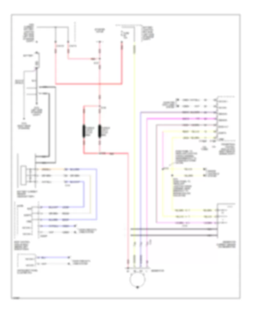 https://portal-diagnostov.com/license.html
Automotive Electricians Portal FZCO
Automotive Electricians Portal FZCO
https://portal-diagnostov.com/license.html
https://portal-diagnostov.com/license.html
Automotive Electricians Portal FZCO
Automotive Electricians Portal FZCOList of elements for Starting Wiring Diagram for Ford Flex SEL 2014:
- (dash panel to headlamp junction wiring harness, near breakout to windshield wiper motor)
- 3.5l
- 3.5l turbo
- Battery
- Battery current sensor (near battery)
- Battery junction box (bjb) (left side of engine compt)
- Bcs
- Bcs2 alt
- Body control module (bcm) (behind left side of dash)
- C1381b
- C144
- C1617c
- C1617d
- C175b
- C2280f
- Cdc10
- Cdc15
- Computer data lines system
- Engine controls system
- Fuse 10a
- Fusible link a (10 ga- red)
- Fusible link b (10 ga- red)
- G103 (left side of engine compt)
- G104 (right rear of engine)
- Gencom
- Generator
- Generator current sensor (on generator)
- Genmon
- High current battery junction box (bjb) (left side of engine compt)
- Hs can +
- Hs can -
- Instrument panel cluster (ipc)
- Ldc59
- Le424
- Micro
- Nca
- Powertrain control module (pcm) (right rear of engine compt)
- Rdc59
- Re407
- Red
- S101 (dash panel to headlamp junction wiring harness, near breakout to engine cooling fan motor)
- S127
- S128
- S129
- S133
- Sdc57
- Sigrtn
- Starter motor
- Vdb04
- Vdb05
- Vdc61
- Vref
SUPPLEMENTAL RESTRAINTS
Supplemental Restraints Wiring Diagram (1 of 3) for Ford Flex SEL 2014
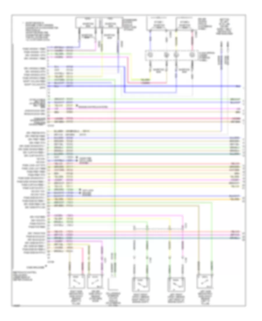 https://portal-diagnostov.com/license.html
Automotive Electricians Portal FZCO
Automotive Electricians Portal FZCO
https://portal-diagnostov.com/license.html
https://portal-diagnostov.com/license.html
Automotive Electricians Portal FZCO
Automotive Electricians Portal FZCOList of elements for Supplemental Restraints Wiring Diagram (1 of 3) for Ford Flex SEL 2014:
- (bottom of left "b" pillar) driver safety belt retractor pretensioner
- Adapt column feed
- Adapt column rtn
- Air bag rtn 1 pass side air bag feed 1
- Anti-lock brakes system
- C145
- C146
- C211
- C216a
- C216b
- C256b
- C310a
- C310b
- C311
- Case grounded
- Cbp41
- Clock spring (under steering wheel)
- Collapsible steering column module (on steering column)
- Computer data lines system
- Cr101
- Cr102
- Cr103
- Cr104
- Cr105
- Cr106
- Cr107
- Cr108
- Cr109
- Cr111
- Cr120
- Cr122
- Cr147
- Cr167
- Cr168
- Cr170
- Cr201
- Cr203
- Cr204
- Cr206
- Driver air bag module (in steering wheel)
- Driver side impact sensor (in driver's door)
- Drv air bag 1 feed
- Drv air bag 1 rtn
- Drv air bag 2 feed
- Drv air bag 2 rtn
- Drv buckle sw
- Drv curtain feed 1
- Drv curtain rtn 1
- Drv fcs feed
- Drv fcs rtn
- Drv pret feed
- Drv pret rtn
- Drv preten feed
- Drv preten rtn
- Drv side air bag feed 1
- Drv side air bag rtn 1
- Drv side feed 2 sn
- Drv side rtn 2 sn
- Drv side sn feed 1
- Drv side sn rtn 1
- Drv track pos
- Engine controls system
- Ens
- Hs can yaw+
- Hs can yaw-
- Hs can+
- Hs can-
- Isp-r
- Left front impact sensor (left front of engine compt)
- Left side second row side impact sensor (left "c" pillar)
- Lr buckle sw src
- Lr inflatable belt rtn lr inflatable belt feed
- Nca
- Pass air bag 1 feed
- Pass air bag 1 rtn
- Pass air bag 2 feed
- Pass air bag 2 rtn
- Pass buckle sw
- Pass curtain feed 1
- Pass curtain rtn 1
- Pass fcs feed
- Pass fcs rtn
- Pass load limit feed
- Pass load limit rtn
- Pass pret feed
- Pass pret rtn
- Pass side
- Pass side air bag feed 1
- Pass side air bag rtn 1
- Pass side sn feed 1
- Pass side sn feed 2
- Pass side sn rtn 1
- Pass side sn rtn 2
- Restraints control module (rcm) (under rear of center console)
- Right front impact sensor (right front of engine compt)
- Right side second row side impact sensor (right "c" pillar)
- Rr buckle sw src
- Rr101
- Rr102
- Rr103
- Rr104
- Rr105
- Rr106
- Rr107
- Rr108
- Rr109
- Rr111
- Rr120
- Rr122
- Rr129
- Rr130
- Rr131
- Rr132
- Rr133
- Rr134
- Rr147
- Rr168
- Rr170
- Shorting bar
- Shorting bar is engaged when harness connector is disconnected from module (shorting bars are connected between the following pins: 1-2, 3-4 of conn c310a)
- Stage 1
- Stage 2
- Stage 2 passenger air bag module (right side of dash)
- Vca23
- Vca24
- Vdb04
- Vdb05
- Vr213
- Vr214
- Vr215
- Vr217
- Vr218
- Vr219
- Vr220
Supplemental Restraints Wiring Diagram (2 of 3) for Ford Flex SEL 2014
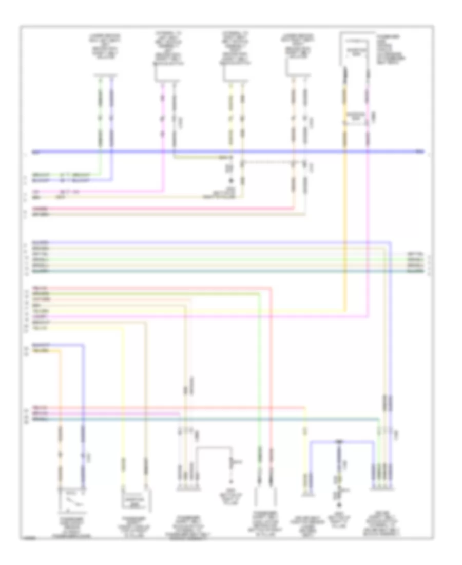 https://portal-diagnostov.com/license.html
Automotive Electricians Portal FZCO
Automotive Electricians Portal FZCO
https://portal-diagnostov.com/license.html
https://portal-diagnostov.com/license.html
Automotive Electricians Portal FZCO
Automotive Electricians Portal FZCOList of elements for Supplemental Restraints Wiring Diagram (2 of 3) for Ford Flex SEL 2014:
- (integral to left seat belt buckle assembly) left second row safety belt buckle switch
- (integral to right seat belt buckle assembly) right second row safety belt buckle switch
- (under second row left seat) left second row safety belt inflator
- (under second row right seat) right second row safety belt inflator
- C212
- C215
- C3050
- C312
- C3133
- C3134
- C340
- Driver safety belt buckle switch (integral to driver seat belt buckle assembly)
- Driver seat position sensor (under driver's seat)
- G300 (bottom of right "c" pillar)
- Nca
- Passenger safety belt buckle switch (integral to passenger seat belt buckle assembly)
- Passenger safety belt load limiting retractor (bottom of right "b" pillar)
- Passenger safety canopy module (top of right "d" pillar)
- Passenger side air bag module (outer edge of passenger seat back)
- Passenger side impact sensor (in front passenger's door)
- S314
- S319
- S351
- Shorting bar
Supplemental Restraints Wiring Diagram (3 of 3) for Ford Flex SEL 2014
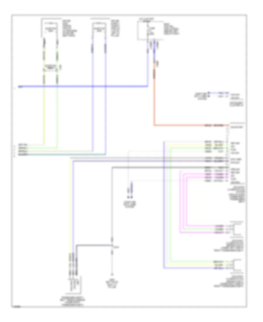 https://portal-diagnostov.com/license.html
Automotive Electricians Portal FZCO
Automotive Electricians Portal FZCO
https://portal-diagnostov.com/license.html
https://portal-diagnostov.com/license.html
Automotive Electricians Portal FZCO
Automotive Electricians Portal FZCOList of elements for Supplemental Restraints Wiring Diagram (3 of 3) for Ford Flex SEL 2014:
- Body control module (bcm) (behind left side of dash)
- Bts sig
- Bts vref
- C2280b
- C2280d
- C3050
- C340
- Cbx02
- Computer data lines system
- Cr153
- Cr154
- Driver safety canopy module (top of left "d" pillar)
- Driver side air bag module (outer edge of driver seat back)
- Fuse 7.5a
- G300 (bottom of right "c" pillar)
- Gd901
- Gnd
- Ground
- Hot in start or run
- Hs can+
- Hs can-
- Instrument cluster (ic)
- Lr142
- Nca
- Occupant classification sensor (ocs) c (under right side of front passenger's seat)
- Occupant classification sensor (ocs) d (under left side of front passenger's seat)
- Occupant classification system module (ocsm) (under front passenger's seat)
- Passenger safety belt tension sensor (under front passenger's seat)
- Pwr
- Return
- Rr153
- Rr154
- Run/start
- S319
- Shorting bar
- Sig
- Vdb04
- Vdb05
- Vr210
- Vr226
- Vr227
TRANSMISSION
A/T Wiring Diagram for Ford Flex SEL 2014
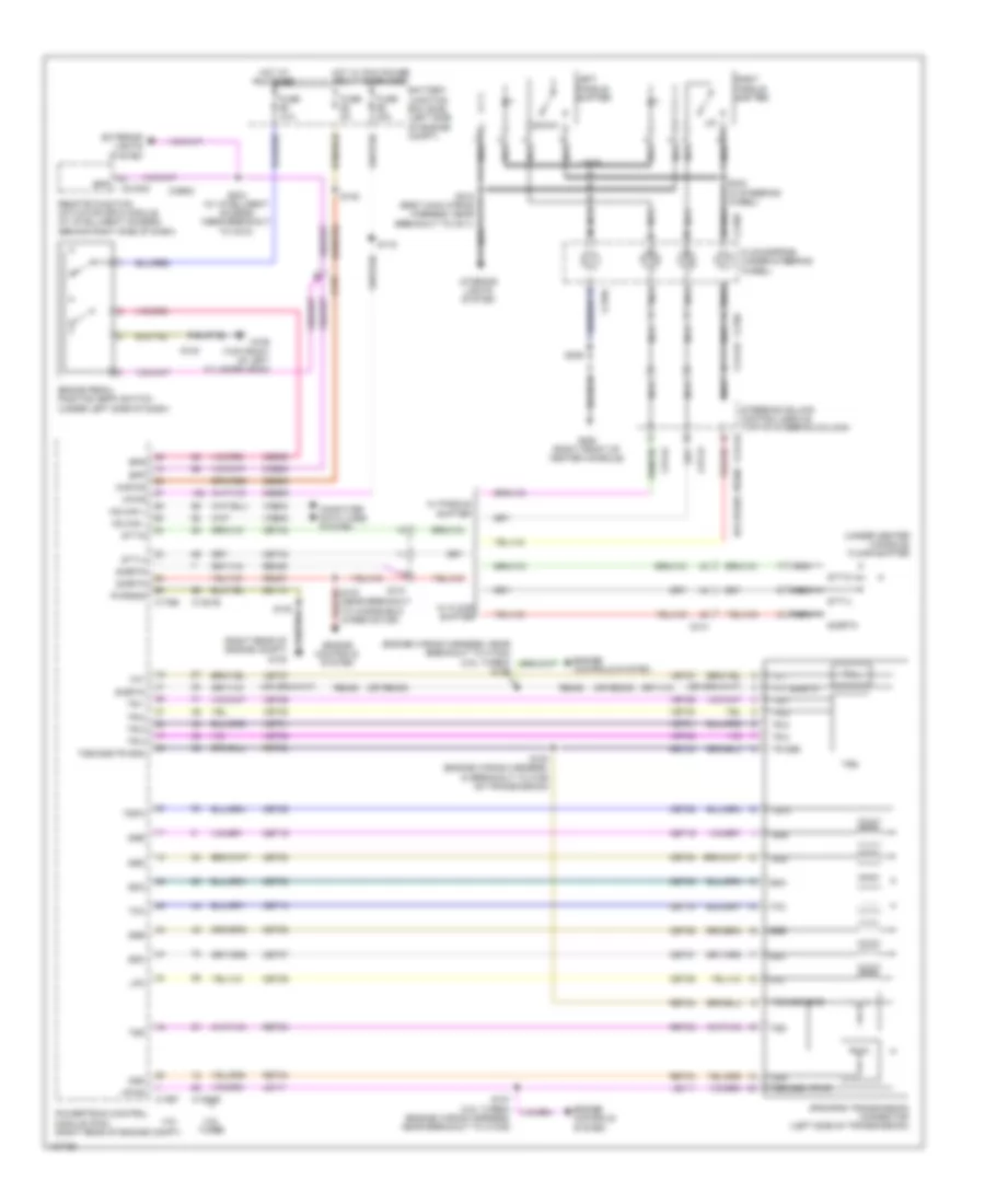 https://portal-diagnostov.com/license.html
Automotive Electricians Portal FZCO
Automotive Electricians Portal FZCO
https://portal-diagnostov.com/license.html
https://portal-diagnostov.com/license.html
Automotive Electricians Portal FZCO
Automotive Electricians Portal FZCOList of elements for A/T Wiring Diagram for Ford Flex SEL 2014:
- (or re405)
- (or re407)
- (right rear of engine compt) g102
- (under center console) floor shifter
- 3.5l
- 3.5l turbo
- 6f50/6f55 transmission connector (left side of transmission)
- Battery junction box (bjb) (left side of engine compt)
- Bpp
- Bps
- Brake pedal position (bpp) switch (under left side of dash)
- C1381b
- C1381e
- C175b
- C175t
- C210
- C214
- C2153c
- C218a
- C218b
- C218c
- C2414a
- C2414d
- Cbb69
- Ccb08
- Ces09
- Cet05
- Cet06
- Cet07
- Cet08
- Cet09
- Cet10
- Cet19
- Cet25
- Cet42
- Cet43
- Clockspring (under steering wheel)
- Computer data lines system
- Down
- Engine controls system
- Exterior lights system
- Fuse 10a
- Fuse 20a
- Fuse 5a
- G106 (top front of left cylinder head)
- G200 (right front of center console)
- Gd113
- Hot at all times
- Hot w/ pcm power relay energized
- Hs can +
- Hs can -
- Interior lights system
- Kapwr
- Le111
- Left paddle shifter
- Lpc
- Nca
- Oss
- Powertrain control module (pcm) (right rear of engine compt)
- Pwrgnd
- Re406
- Re407
- Remote function actuator (rfa) module (w/ intelligent access) (behind right side of dash)
- Ret04
- Ret24
- Ret33
- Right paddle shifter
- S100 (engine wiring harness, in breakout to c168 on transmission)
- S107 (3.5l turbo) (engine wiring harness, near breakout to c1045)
- S116
- S126
- S130
- S133 (near breakout to windshield wiper motor)
- S138
- S204 (w/ intelligent access) (near breakout to c210)
- S206
- S215 (body main wiring harness, near breakout to c211)
- S242 (in steering wheel)
- S299
- Sbb86
- Sigrtn
- Ssa
- Ssb
- Ssc
- Ssd
- Sse
- Steering column control module (top of steering column)
- Stt-d
- Stt-u
- Tcc
- Tft
- Tft sigrtn
- Tr gnd
- Tr-1
- Tr-2
- Tr-3
- Tr-4
- Trs
- Tspc
- Tss
- Tss/oss gnd
- Tss/oss vpwr
- Tss/oss/tr gnd
- Vdb04
- Vdb05
- Vet27
- Vet29
- Vet30
- Vet31
- Vet32
- Vpwr
- W/ floor shifter
- W/ paddle shifter
AWD Wiring Diagram for Ford Flex SEL 2014
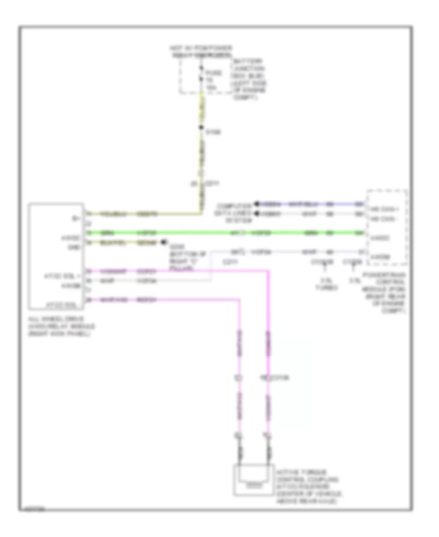 https://portal-diagnostov.com/license.html
Automotive Electricians Portal FZCO
Automotive Electricians Portal FZCO
https://portal-diagnostov.com/license.html
https://portal-diagnostov.com/license.html
Automotive Electricians Portal FZCO
Automotive Electricians Portal FZCOList of elements for AWD Wiring Diagram for Ford Flex SEL 2014:
- 3.5l
- 3.5l turbo
- Active torque control coupling (atcc) solenoid (center of vehicle, above rear axle)
- All wheel drive (awd) relay module (right kick panel)
- Atcc sol +
- Atcc sol -
- Awdc
- Awdm
- Battery junction box (bjb) (left side of engine compt)
- C1381b
- C175b
- C211
- C3138
- Cbb70
- Ccf21
- Computer data lines system
- Fuse 15a
- G300 (bottom of right "c" pillar)
- Gd348
- Gnd
- Hot w/ pcm power relay energized
- Hs can +
- Hs can -
- Nca
- Powertrain control module (pcm) (right rear of engine compt)
- Rcf21
- S108
- Vcf34
- Vcf35
- Vdb04
- Vdb05
TRUNK, TAILGATE, FUEL DOOR
Liftgate Release Wiring Diagram for Ford Flex SEL 2014
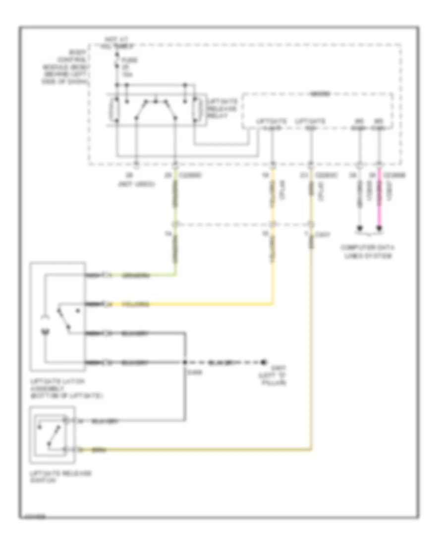 https://portal-diagnostov.com/license.html
Automotive Electricians Portal FZCO
Automotive Electricians Portal FZCO
https://portal-diagnostov.com/license.html
https://portal-diagnostov.com/license.html
Automotive Electricians Portal FZCO
Automotive Electricians Portal FZCOList of elements for Liftgate Release Wiring Diagram for Ford Flex SEL 2014:
- (not used)
- Body control module (bcm) (behind left side of dash)
- C2280b
- C2280c
- C2280d
- C431
- Computer data
- Cpl44
- Cpl45
- Fuse 15a
- G401 (left "d" pillar)
- Hot at all times
- Liftgate ajar
- Liftgate latch assembly (bottom of liftgate)
- Liftgate release relay
- Liftgate release switch
- Liftgate sw
- Lines system
- Micro
- Ms can+
- Ms can-
- Nca
- S406
- Vdb06
- Vdb07
Power Liftgate Wiring Diagram for Ford Flex SEL 2014
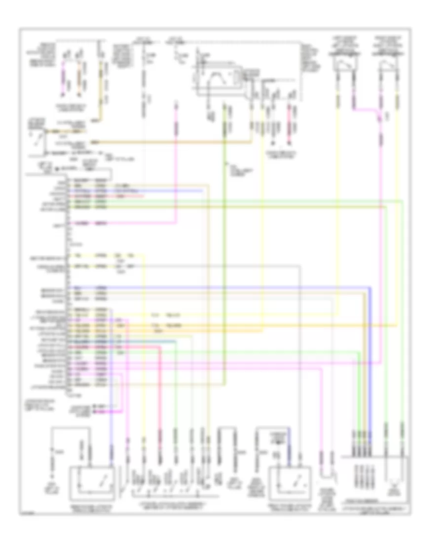 https://portal-diagnostov.com/license.html
Automotive Electricians Portal FZCO
Automotive Electricians Portal FZCO
https://portal-diagnostov.com/license.html
https://portal-diagnostov.com/license.html
Automotive Electricians Portal FZCO
Automotive Electricians Portal FZCOList of elements for Power Liftgate Wiring Diagram for Ford Flex SEL 2014:
- (left "d" pillar) g401
- (left side of liftgate) left liftgate obstacle detection strip
- (not used)
- (right side of liftgate) right liftgate obstacle detection strip
- (w/ 60/40 bench) s419
- Ajar liftgate
- Battery junction box (bjb) (left side of engine compt)
- Body control module (bcm) (behind left side of dash)
- C211
- C215
- C2153b
- C2153e
- C2280b
- C2280c
- C2280d
- C4174a
- C4174b
- C431
- Can + ms
- Can - ms
- Chime +
- Chime -
- Cinch
- Cinch motor
- Computer data lines system
- Console open/ close sw
- Cpl44
- Cpl45
- Cpl84
- Cpr51
- Cpr52
- Cpr55
- Cpr56
- Cpr57
- Cpr58
- Cpr61
- Cpr62
- Cpr63
- Cpr64
- Cpr65
- Cpr66
- Cpr67
- Cpr68
- Cpr89
- Front power liftgate open/close switch
- Fuse 10a
- Fuse 15a
- Fuse 30a
- G200 (right front of center console)
- G401 (left "d" pillar)
- Gd349
- Gnd
- Hot at all times
- Interior lights system
- Latch sw full
- Latch sw half
- Latch sw half sensor pwr
- Liftgate ajar
- Liftgate driver motor assembly (left "d" pillar)
- Liftgate latch/unlatch assembly (center of liftgate assembly)
- Liftgate release
- Liftgate release relay
- Liftgate release switch
- Liftgate/trunk module (ltm) (left "d" pillar)
- Lt pinch strip sig sector gear sw 1 rt pinch strip sig
- Micro
- Motor close
- Motor open
- Ms can +
- Ms can -
- Nca
- Pinch strip rtn
- Position sensor
- Power liftgate chime (base of left "d" pillar)
- Ratchet sw
- Rear power liftgate open/close switch
- Remote function actuator (rfa) module (behind right side of dash)
- Rpr52
- Rpr55
- Rpr56
- Rr interior sw
- S205
- S406
- S420
- Sbb07
- Sbp08
- Sector gear sw 1
- Sector gear sw 2
- Sensor pwr
- Sensor rtn
- Sensor sig 1
- Sensor sig 2
- Sw liftgate
- Uncinch
- Vbatt
- Vdb06
- Vdb07
- Vpr53
- Vpr54
- W/ intelligent access
- W/0 intelligent access
- W/o intelligent access
WARNING SYSTEMS
Chime Wiring Diagram (1 of 2) for Ford Flex SEL 2014
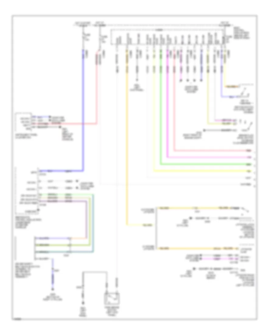 https://portal-diagnostov.com/license.html
Automotive Electricians Portal FZCO
Automotive Electricians Portal FZCO
https://portal-diagnostov.com/license.html
https://portal-diagnostov.com/license.html
Automotive Electricians Portal FZCO
Automotive Electricians Portal FZCOList of elements for Chime Wiring Diagram (1 of 2) for Ford Flex SEL 2014:
- Body control module (bcm) (behind left side of dash)
- Brake fluid level switch (on brake fluid reservoir)
- Brk fluid sw rtn
- C2280a
- C2280b
- C2280c
- C2280d
- C2280f
- C2280g
- C310a
- C310b
- C340
- C4174a
- C4174b
- C431
- Case gnd
- Cbp41
- Cdc30
- Cmc19
- Cmc25
- Computer data lines system
- Cpl26
- Cpl31
- Cpl36
- Cpl39
- Cpl44
- Cr120
- Cr201
- Driver safety belt buckle switch (integral to driver seat belt buckle assembly)
- Drv buck feed
- Drv buck rtn
- Drv buck sw
- Fuse 15a
- Fuse 5a
- Fuse 7.5a
- G100 (right front of engine compt)
- G201 (left front of center console)
- G300 (bottom of right "c" pillar)
- G301 (left kick panel)
- G401 (left "d" pillar)
- Gd233
- Gd349
- Gnd
- Hot at all times
- Hot in start or run
- Hs can +
- Hs can -
- Hs can+
- Hs can-
- Ignition switch (w/o intelligent access)
- Instrument panel cluster (ipc)
- Isp-r
- Key in
- Key in ignition
- Lf door ajar
- Liftgate ajar
- Liftgate latch assembly (w/o power liftgate) (bottom of liftgate)
- Liftgate/ ajar
- Liftgate/trunk module (ltm) (w/ power liftgate) (left "d" pillar)
- Lr door ajar
- Micro
- Ms can +
- Ms can -
- Ms can+
- Ms can-
- Nca
- Park brake
- Park brake switch (left kick panel)
- Pwr gnd
- Red
- Restraints control module (rcm) (under rear of center console)
- Rf door ajar
- Rmc19
- Rr door ajar
- Rr120
- S305
- S351
- S406
- S419 (w/ 60/40 bench)
- Sbf01
- Sw brk fluid
- Vbatt
- Vdb04
- Vdb05
- Vdb06
- Vdb07
- Vdbo5
- Vdbo7
- W/ power liftgate
- W/o power liftgate
Chime Wiring Diagram (2 of 2) for Ford Flex SEL 2014
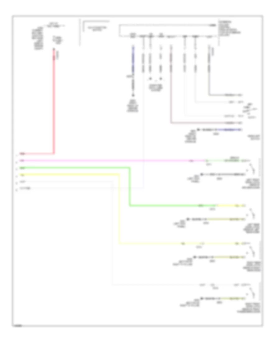 https://portal-diagnostov.com/license.html
Automotive Electricians Portal FZCO
Automotive Electricians Portal FZCO
https://portal-diagnostov.com/license.html
https://portal-diagnostov.com/license.html
Automotive Electricians Portal FZCO
Automotive Electricians Portal FZCOList of elements for Chime Wiring Diagram (2 of 2) for Ford Flex SEL 2014:
- Auto 1
- C1617b
- C2414a
- C311
- C312
- C313
- C314
- Clf19
- Clf23
- Clf24
- Cls34
- Computer data lines system
- G200 (right front of center console)
- G300 (bottom of right "c" pillar)
- G301 (left kick panel)
- Gd375
- Headlamp switch
- High current battery junction box (bjb) (left side of engine compt)
- Hot at all times
- Hs can+
- Hs can-
- Left front door latch (rear of driver's door)
- Left rear door latch (rear of left rear door)
- Logic gnd
- Low
- Mega fuse 1 100a
- Micro
- Multi-function switch
- Off
- Park
- Red
- Right front door latch (rear of front passenger's door)
- Right rear door latch (rear of right rear door)
- S205
- S206
- S500
- S600
- S700
- S800
- Sbp23
- Steering column control module (sccm) (top of steering column)
- Vbatt
- Vdb04
- Vdb05
Tire Pressure Monitoring Wiring Diagram for Ford Flex SEL 2014
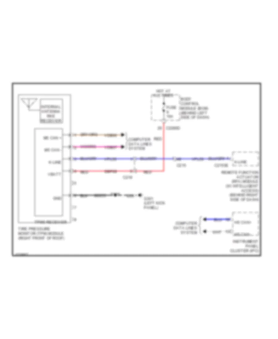 https://portal-diagnostov.com/license.html
Automotive Electricians Portal FZCO
Automotive Electricians Portal FZCO
https://portal-diagnostov.com/license.html
https://portal-diagnostov.com/license.html
Automotive Electricians Portal FZCO
Automotive Electricians Portal FZCOList of elements for Tire Pressure Monitoring Wiring Diagram for Ford Flex SEL 2014:
- Body control module (bcm) (behind left side of dash)
- C215
- C2153e
- C219
- C2280d
- Computer data lines system
- Fuse 10a
- G301 (left kick panel)
- Gd233
- Gnd
- Hot at all times
- Hs can+
- Hs can-
- Instrument panel cluster (ipc)
- Internal antenna rke receiver
- K-line
- Ms can +
- Ms can -
- Red
- Remote function actuator (rfa) module (w/ intelligent access) (behind right side of dash)
- S900
- Sbp09
- Tire pressure monitor (tpm) module (right front of roof)
- Tpms receiver
- Vbatt
- Vdb06
- Vdb07
- Vpl56
WIPER/WASHER
Wiper/Washer Wiring Diagram for Ford Flex SEL 2014
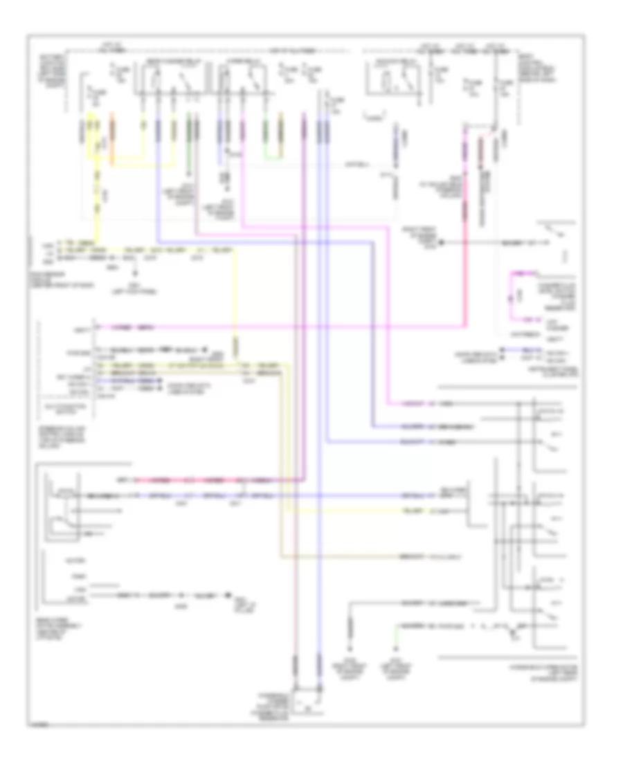 https://portal-diagnostov.com/license.html
Automotive Electricians Portal FZCO
Automotive Electricians Portal FZCO
https://portal-diagnostov.com/license.html
https://portal-diagnostov.com/license.html
Automotive Electricians Portal FZCO
Automotive Electricians Portal FZCOList of elements for Wiper/Washer Wiring Diagram for Ford Flex SEL 2014:
- (right front of engine compt) g100
- Battery junction box (bjb) (left side of engine compt)
- Body control module (bcm) (behind left side of dash)
- C210
- C211
- C215
- C219
- C2280a
- C2280f
- C2414a
- C2414b
- C431
- Cbb45
- Computer data lines system
- Crw15
- Frt wiper hi
- Fuse 10a
- Fuse 15a
- Fuse 30a
- Fuse 5a
- G100 (right front of engine compt)
- G101 (left front of engine compt)
- G200 (right front of center console)
- G301 (left kick panel)
- G401 (left "d" pillar)
- Gd233
- Gd375
- Gnd
- Hi input
- Hot at all times
- Hs can +
- Hs can -
- Instrument panel cluster (ipc)
- Lin
- Logic gnd
- Low washer
- Micro
- Motor+
- Motor-
- Multi-function switch
- Park
- Power distribution system
- Pwr gnd
- Rain sensor module (center front of roof)
- Rear washer relay
- Rear wiper motor assembly (center of liftgate)
- Rr wash rly
- Rr wiper in
- Rr wiper mtr
- Run/acc relay
- S143
- S202 (w/ adjustable steering column)
- S206
- S406
- S904
- Sbp24
- Steering column control module (top of steering column)
- Vbatt
- Vdb04
- Vdb05
- Vdn05
- Vign
- Wash
- Washer fluid level switch (washer fluid reservoir)
- Windshield washer pump motor (washer fluid reservoir)
- Windshield wiper motor (left rear of engine compt)
- Wiper relay

 Čeština
 Dansk
Dansk Deutsch
 Ελληνικά
 English
 English
 Español
 Suomi
Suomi Français
 Français
 Hrvatski
 Magyar
 Italiano
 日本語
日本語 한국어
한국어 Nederlands
 Polski
 Português
 Português
 Română
 Русский
 Slovenčina
 Slovenščina
 Svenska
 Türkçe
 中文 (中国)
