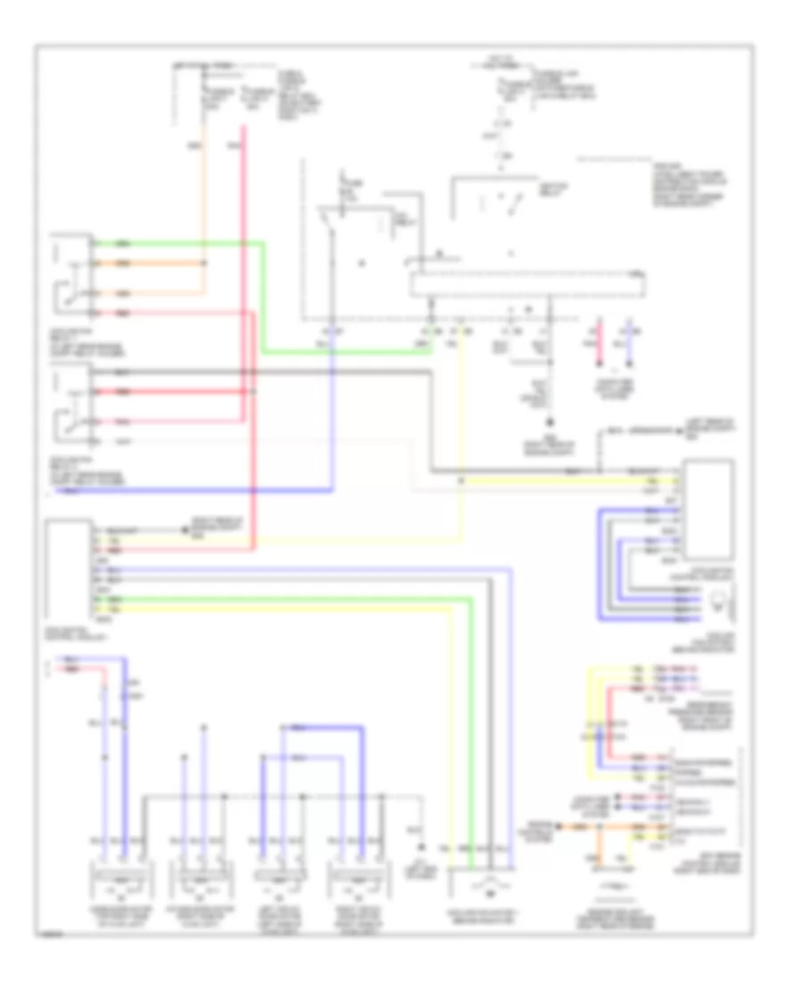
AIR CONDITIONING
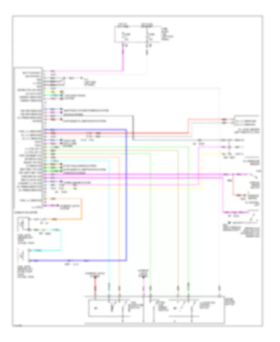
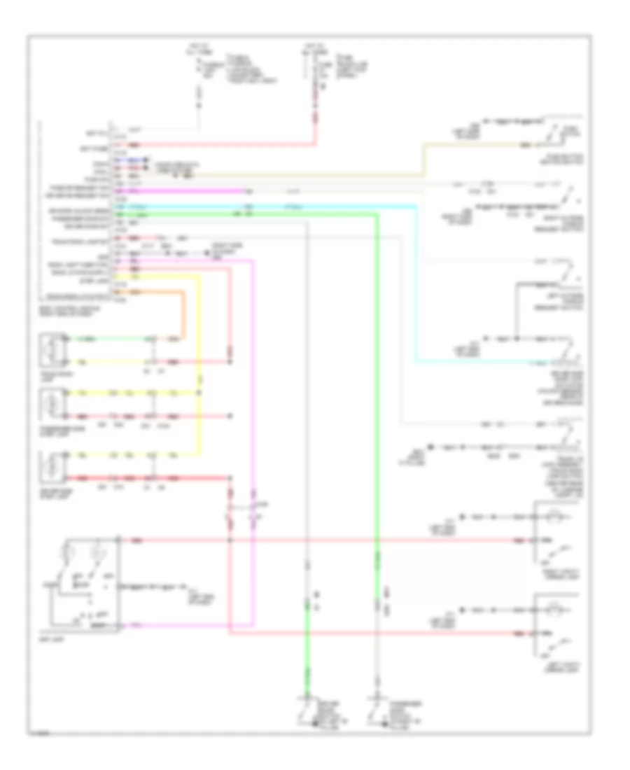
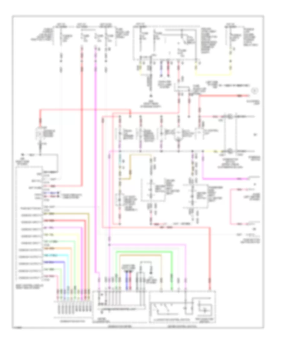
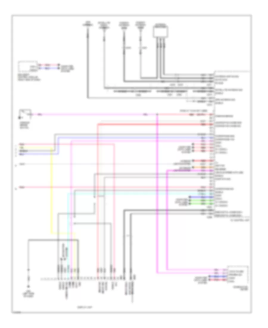
Automatic A/C Wiring Diagram (1 of 2) for Nissan GT-R Premium 2014
 https://portal-diagnostov.com/license.html
Automotive Electricians Portal FZCO
Automotive Electricians Portal FZCO
https://portal-diagnostov.com/license.html
https://portal-diagnostov.com/license.html
Automotive Electricians Portal FZCO
Automotive Electricians Portal FZCO
List of elements for Automatic A/C Wiring Diagram (1 of 2) for Nissan GT-R Premium 2014:
- (left end of dash) m11
- 2a m1
- 3a m1
- 6b m2
- 6f e10b
- 7c m3
- A/c auto amp
- A/c auto amplifier (center of dash)
- A/c lan signal
- A/o auto amp
- Ambient sen sig
- Ambient sens gnd
- Ambient sensor (center front of engine compt)
- Ambient sensor signal
- Amp
- Av comm (h)
- Av comm (l)
- Av control unit
- Blower motor (right side of dash)
- Blower motor ctrl sig
- Blower relay
- Blwr mtr rly
- Body control module (right end of dash)
- Can-h
- Can-l
- Combination meter
- Comm
- Compressor (magnetic clutch) (left front of engine)
- Computer data lines system
- E101 1d
- E106
- Each dr motor pwr sply
- Ecv
- Ecv signal
- F103
- F35
- F36
- Fuse 10a
- Fuse 15a
- Fuse block (j/b) (left kick panel)
- Fusible link e 80a
- Fusible link holder (on fuse/ fusible link & relay box)
- Ground
- Hot at all times
- Hot in acc or on
- Hot in on or start
- In-vehicle sensor (lower left center of dash)
- In-vehicle sensor signal
- Intake sensor (center right side of dash)
- Intake sensor signal
- M106
- M11 (left end of dash)
- M116
- M122
- Magnet clutch
- Multi- function switch
- Pnk
- Red
- Sensor ground
- Shield
- Sound systems
- Sunload sensor (top right side of dash)
- Sunload sensor signal
Automatic A/C Wiring Diagram (2 of 2) for Nissan GT-R Premium 2014
 https://portal-diagnostov.com/license.html
Automotive Electricians Portal FZCO
Automotive Electricians Portal FZCO
https://portal-diagnostov.com/license.html
https://portal-diagnostov.com/license.html
Automotive Electricians Portal FZCO
Automotive Electricians Portal FZCOList of elements for Automatic A/C Wiring Diagram (2 of 2) for Nissan GT-R Premium 2014:
- (left rear of engine compt) e20
- (right rear of engine compt) e46
- A/c relay
- Amp
- Avcc2-pd/pspres
- Computer data lines system
- Cooling fan control module 1
- Cooling fan control module 2
- Cooling fan motor 1 (behind radiator)
- Cooling fan motor 2 (behind radiator)
- Cooling fan relay 1 (in left rear engine compt relay holder)
- Cooling fan relay 2 (in left rear engine compt relay holder)
- Cpu
- E301
- E302
- E303
- E304
- E35
- E37
- E46 (right rear of engine compt)
- Ecm (engine control module) (right end of dash)
- Engine controls system
- Engine coolant temperature sensor (right rear of engine)
- F101
- F102
- F103
- Fuse & fusible link & relay box (on battery positive (+) post)
- Fuse 10a
- Fusible link c 80a
- Fusible link f 50a
- Fusible link holder (on fuse/fusible link & relay box)
- Fusible link m 50a
- Gnda-pd/pspres
- Gnda-tw/to/tf
- Hot at all times
- Ignition relay
- Intake door motor (right side of hvac unit)
- Ipdm e/r (intelligent power distribution module engine room) (right rear corner of engine compt)
- Left air mix door motor (left side of hvac unit)
- M107
- M11 (left end of dash)
- M116
- M251
- M6 e106
- M91
- Mode door motor (top right side of hvac unit)
- Pdpres
- Pnk
- Red
- Refrigerant pressure sensor (right front of engine compt)
- Right air mix door motor (right side of hvac unit)
- Vehcan-h1
- Vehcan-l1
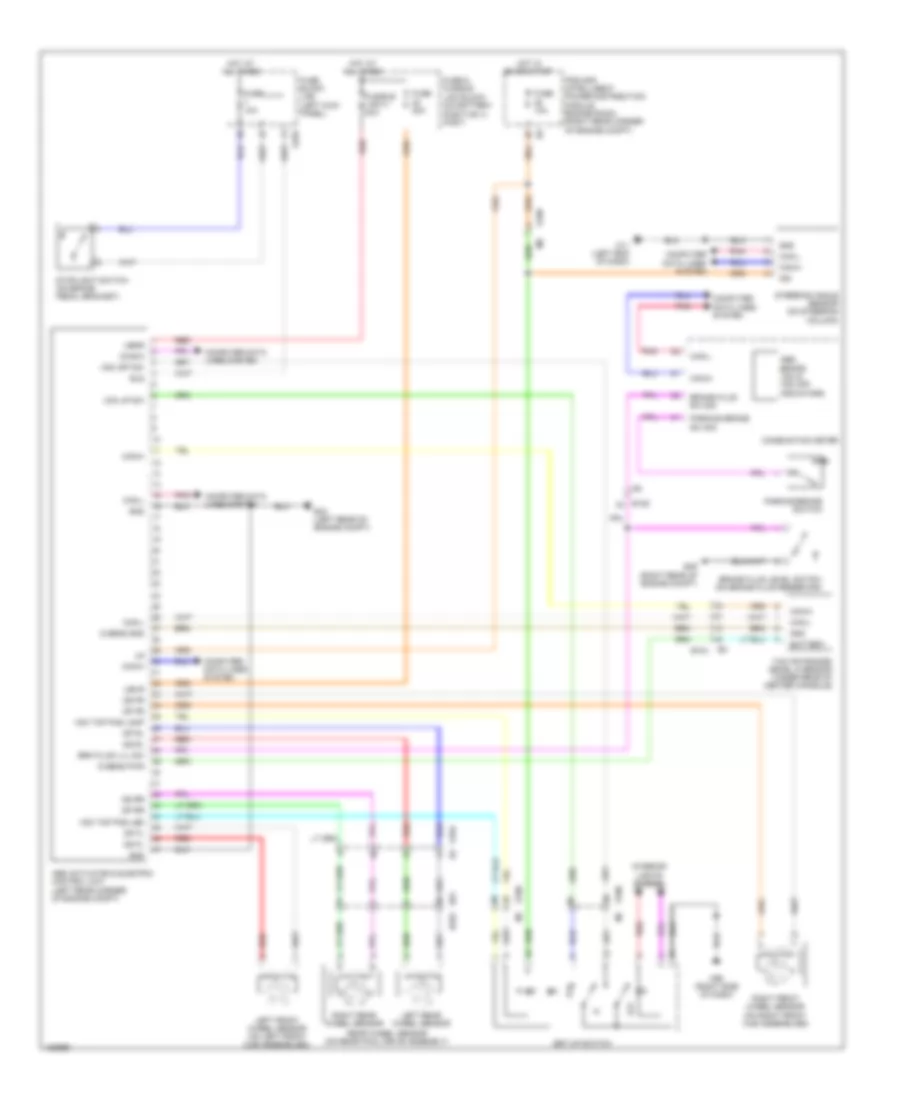
ANTI-LOCK BRAKES
Anti-lock Brakes Wiring Diagram for Nissan GT-R Premium 2014
 https://portal-diagnostov.com/license.html
Automotive Electricians Portal FZCO
Automotive Electricians Portal FZCO
https://portal-diagnostov.com/license.html
https://portal-diagnostov.com/license.html
Automotive Electricians Portal FZCO
Automotive Electricians Portal FZCOList of elements for Anti-lock Brakes Wiring Diagram for Nissan GT-R Premium 2014:
- Abs actuator & electric control unit (left rear corner of engine compt)
- Abs, brake, vdc & vdc off indicators
- B61 b252
- Battery
- Bls
- Brake fluid level switch (on brake fluid reservoir)
- Brake fluid sw sig
- Brk fluid lvl sw
- Can-h
- Can-l
- Combination meter
- Computer data lines system
- Diag-k
- Dp fl
- Dp fr
- Dp rl
- Dp rr
- Ds fl
- Ds fr
- Ds rl
- Ds rr
- E103
- E104
- E104 b3
- E106
- E43 (left rear of engine compt)
- E46 (right rear of engine compt)
- Fuse & fusible
- Fuse 10a
- Fuse 20a
- Fuse block (j/b) (left kick panel)
- Fusible link h 40a
- G sens gnd
- G sens pwr
- Gnd
- Hot at all times
- Hot in on or start
- Ign
- Interior lights system
- Ipdm e/r (intelligent power distribution module engine room) (right rear corner of engine compt)
- Left front wheel sensor (on left front hub assemblies)
- Left rear wheel sensor
- Link block (on battery positive (+) post)
- M11 (left end of dash)
- M95 (right side of dash)
- Off
- Parking brake sw sig
- Parking brake switch
- Pnk
- Rear wheel sensor (on rear final drive assembly)
- Red
- Right front wheel sensor (on right front hub assemblies)
- Right rear wheel sensor
- Set-up switch
- Steering angle sensor (on steering column)
- Stoplight switch (on brake pedal bracket)
- Ubmr
- Ubvr
- Vda up sw
- Vdc off sw
- Vdc top pas lamp
- Vdc top pos led
- Yaw rate/side/ decel g sensor (under rear of center console)
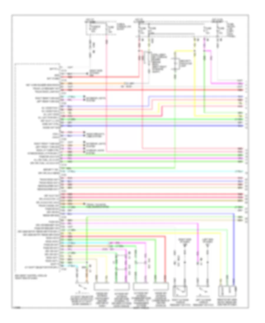
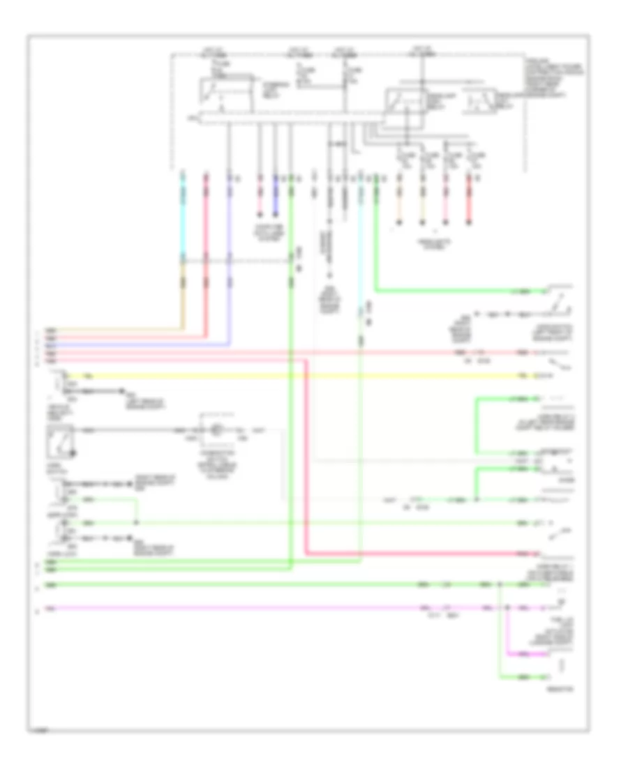
ANTI-THEFT
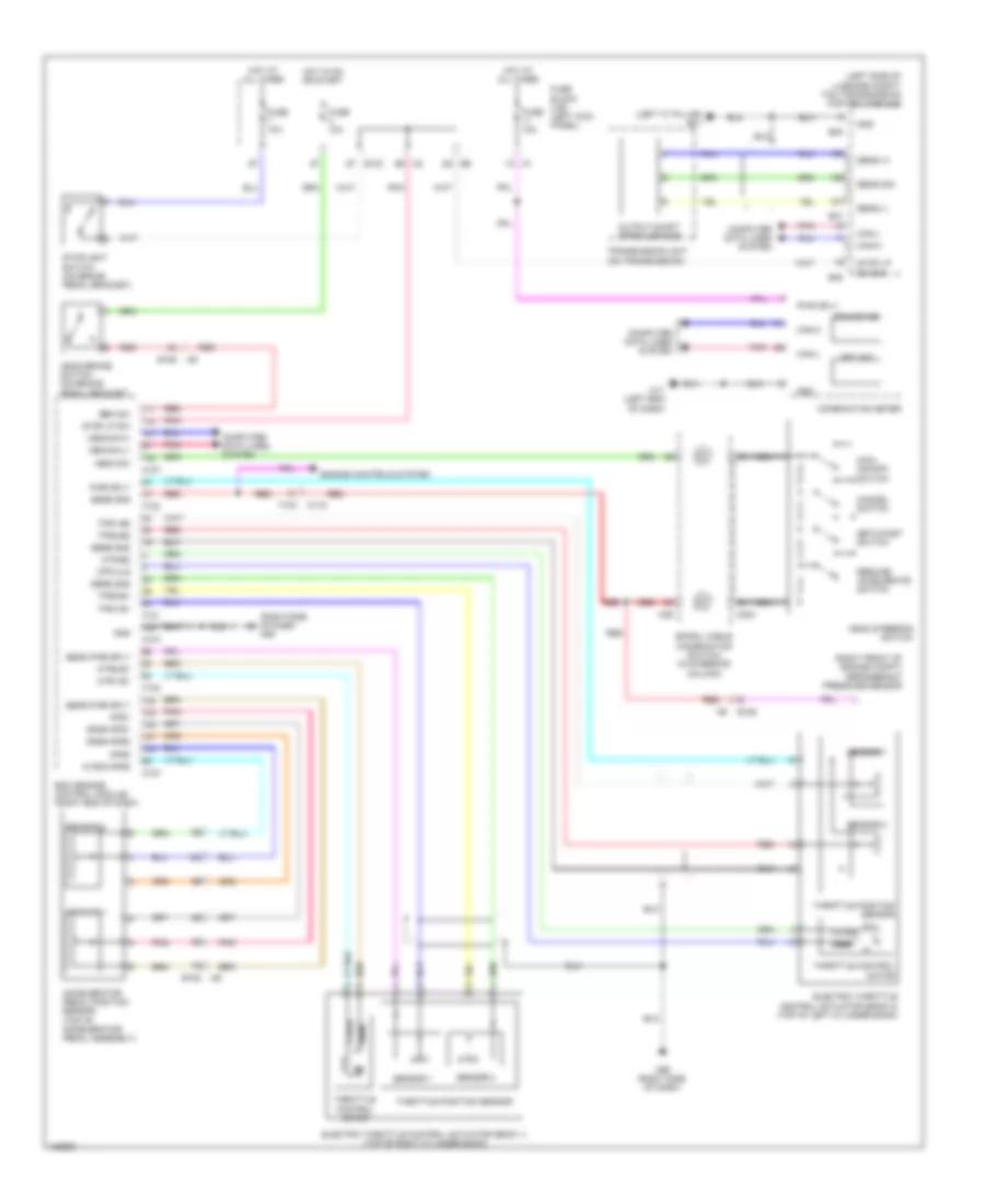
Anti-theft Wiring Diagram, with Intelligent Key Unit (1 of 3) for Nissan GT-R Premium 2014
 https://portal-diagnostov.com/license.html
Automotive Electricians Portal FZCO
Automotive Electricians Portal FZCO
https://portal-diagnostov.com/license.html
https://portal-diagnostov.com/license.html
Automotive Electricians Portal FZCO
Automotive Electricians Portal FZCOList of elements for Anti-theft Wiring Diagram, with Intelligent Key Unit (1 of 3) for Nissan GT-R Premium 2014:
- (left end of dash) m11
- (right side of dash) m95
- 11f
- 12c
- A/t shift selector (detention switch) (base of a/t shift lever assembly)
- A/t shift selector pwr sply
- All dr, fuel lid lk o/p
- Bat (f/l)
- Bat (fuse)
- Batt
- Bcm (body control module) (right end of dash)
- Can-h
- Can-l
- Computer data lines system
- D12 d21
- D31
- D42 d51
- Dr lk/unlk sw lk
- Dr lk/unlk sw unlk
- Drv dr ant+
- Drv dr ant-
- Drv dr request sw
- Drv dr sw
- Drv dr unlk sens
- Drv dr, fuel lid unlk o/p
- E103
- E106
- Exterior lights system
- Fuse & fusible link block
- Fuse 10a
- Fuse 15a
- Fuse block (j/b) (left kick panel)
- Fusible link i 40a
- Gnd
- Hot at all times
- Hot in on or start
- Immbi ant ctrl
- Immobi ant sig
- Inside key antenna (console) (under rear of center console)
- Inside key antenna (instrument center) (center of dash)
- Intelligent key warning buzzer (engine room) (right front of engine compt)
- Interior lights system
- Interior room lp pwr sply
- Key slot ill o/p
- Key slot sw
- Key warn buzzer (eng room)
- Keyless entry receiver comm
- Keyless entry receiver pwr sply
- Left front turn sig
- Left outside handle (request switch)
- Left rear turn sig
- M118
- M119
- M120
- M121
- M122
- M123
- M124
- M124 d31
- M5 d1
- M7 b1
- Outside key antenna (driver side) (integral to driver's outside door handle)
- Outside key antenna (passenger side) (integral to passenger's outside door handle)
- Pass dr ant+
- Pass dr ant-
- Pass dr request sw
- Pass dr sw
- Pass dr unlk o/p
- Pnk
- Push sw
- Rear bumper ant+
- Rear bumper ant-
- Receiver gnd
- Red
- Remote keyless entry receiver (center of dash)
- Right front turn sig
- Right outside handle (request switch)
- Right rear turn sig
- Room ant1+
- Room ant1-
- Room ant2+
- Room ant2-
- Room lp timer ctrl
- S/l condition 1
- S/l condition 2
- S/l unit comm
- S/l unit pwr sply
- Security ind
- Security indicator lamp
- Shift p
- Sig out
- Trunk cancel sw
- Trunk lid request sw
- Trunk room ant+
- Trunk room ant-
- Trunk room lamp sw
- Trunk, tailgate, fuel doors system
Anti-theft Wiring Diagram, with Intelligent Key Unit (2 of 3) for Nissan GT-R Premium 2014
 https://portal-diagnostov.com/license.html
Automotive Electricians Portal FZCO
Automotive Electricians Portal FZCO
https://portal-diagnostov.com/license.html
https://portal-diagnostov.com/license.html
Automotive Electricians Portal FZCO
Automotive Electricians Portal FZCOList of elements for Anti-theft Wiring Diagram, with Intelligent Key Unit (2 of 3) for Nissan GT-R Premium 2014:
- (left end of dash) m11
- (right side of dash) m95
- B151
- B201
- B231 (right "c" pillar)
- B239
- B31 (left "c" pillar)
- B351
- B59
- Bat
- Batt pwr sply
- Buzzer
- Can-h
- Can-l
- Clock
- Combination meter
- Computer data lines system
- Condenser (rear of engine)
- D31
- Data
- Door lock actuator
- Driver side door lock actuator (rear of driver's door)
- Driver side door switch (in left "b" pillar)
- Gnd
- Ign pwr sply
- Ill
- Ill bat
- Inside key antenna (trunk room) (center front of luggage compt)
- Key ind
- Key slot
- Key sw sig
- Lock
- M11 (left end of dash)
- M117
- M124
- M95 (right side of dash)
- Outside key antenna (rear bumper) (center of rear bumper)
- Passenger side door lock actuator (rear of front passenger's door)
- Passenger side door switch (in right "b" pillar)
- Pnk
- Power window main-switch
- Power window sub-switch
- Push button ignition switch
- Red
- Resistor m126 (right center of dash)
- S/l (k line)
- S/l 12v (cpu)
- S/l 12v (mechanical)
- S/l condition 1
- S/l condition 2
- Steering lock unit (on steering column)
- Trunk lid lock assembly
- Trunk lid opener request switch
- Trunk room lamp switch
- Un lock
- Unified meter control unit
- Unlock sensor
Anti-theft Wiring Diagram, with Intelligent Key Unit (3 of 3) for Nissan GT-R Premium 2014
 https://portal-diagnostov.com/license.html
Automotive Electricians Portal FZCO
Automotive Electricians Portal FZCO
https://portal-diagnostov.com/license.html
https://portal-diagnostov.com/license.html
Automotive Electricians Portal FZCO
Automotive Electricians Portal FZCOList of elements for Anti-theft Wiring Diagram, with Intelligent Key Unit (3 of 3) for Nissan GT-R Premium 2014:
- (right rear of engine compt) e46
- B201
- Combination switch (spiral cable) (in steering column)
- Computer data lines system
- Cpu
- Diode
- E106
- E106 m6
- E20 (left rear of engine compt)
- E32
- E33
- E46 (right rear of engine compt)
- E79
- E80
- E81
- E82
- Fuel lid lock actuator (right side of luggage compt)
- Fuse 10a
- Fuse 15a
- Headlamp high relay
- Headlamp low relay
- Headlights system
- Hood switch (left front of engine compt)
- Horn (high)
- Horn (low)
- Horn relay 1 (on fuse/fusible link & relay box)
- Horn relay 2 (in left rear engine compt relay holder)
- Horn switch
- Hot at all times
- Ipdm e/r (intelligent power distribution module engine room) (right rear corner of engine compt)
- M117
- M303
- M36
- Nca
- Pnk
- Red
- Resistor
- Steering lock relay
- Vehicle security horn
Anti-theft Wiring Diagram, without Intelligent Key Unit for Nissan GT-R Premium 2014
 https://portal-diagnostov.com/license.html
Automotive Electricians Portal FZCO
Automotive Electricians Portal FZCO
https://portal-diagnostov.com/license.html
https://portal-diagnostov.com/license.html
Automotive Electricians Portal FZCO
Automotive Electricians Portal FZCOList of elements for Anti-theft Wiring Diagram, without Intelligent Key Unit for Nissan GT-R Premium 2014:
- (right side of dash) m95
- All dr, fuel lid lk o/p
- B201
- B201 m117
- Bat (f/l)
- Bat (fuse)
- Bcm (body control module) (right end of dash)
- Can-h
- Can-l
- Computer data lines system
- Condenser (rear of engine)
- D31
- D31 m124
- Door lock actuator
- Dr lk/unlk sw lk
- Dr lk/unlk sw unlk
- Driver door switch (in driver "b" pillar)
- Driver side door lock actuator (rear of driver's door)
- Drv dr sw
- Drv dr unlk sens
- Drv dr, fuel lid unlk o/p
- E106 m6
- Fuel lid opener actuator
- Fuse & fusible link block
- Fuse 10a
- Fuse block (j/b) (left kick panel)
- Fusible link i 40a
- Gnd
- Hot at all times
- Ill
- Key slot
- Key slot ill o/p
- Key slot sw
- Key sw sig
- Lock
- M11 (left end of dash)
- M117
- M118
- M119
- M122
- M123
- M124
- M124 m31
- M95 (right side of dash)
- Pass dr sw
- Pass dr unlk o/p
- Passenger door switch (in passenger "b" pillar)
- Passenger side door lock actuator (rear of front passenger's door)
- Pnk
- Power window main-switch
- Power window sub-switch
- Red
- Resistor b245 (right "c" pillar)
- Resistor m126 (right center of dash)
- Un lock
- Unlock sensor
BODY CONTROL MODULES
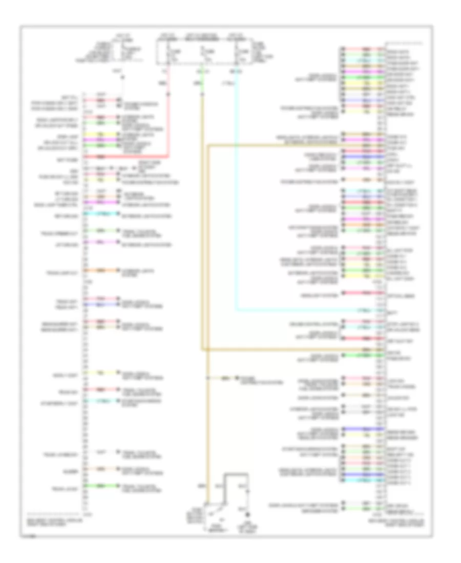
Body Control Modules Wiring Diagram for Nissan GT-R Premium 2014
 https://portal-diagnostov.com/license.html
Automotive Electricians Portal FZCO
Automotive Electricians Portal FZCO
https://portal-diagnostov.com/license.html
https://portal-diagnostov.com/license.html
Automotive Electricians Portal FZCO
Automotive Electricians Portal FZCOList of elements for Body Control Modules Wiring Diagram for Nissan GT-R Premium 2014:
- (right side of dash) m95
- 9b m2
- A/t shift sele- ctor pwr sply
- Acc ind
- Acc rly cont
- Air conditioning system door locks & anti-theft systems
- Anti-theft system
- Bat (f/l)
- Bat (fuse)
- Batt
- Bcm (body control module) (right end of dash)
- Buzzer
- Can-h
- Can-l
- Combi in 1
- Combi in 2
- Combi in 3
- Combi in 4
- Combi in 5
- Combi out 1
- Combi out 2
- Combi out 3
- Combi out 4
- Combi out 5
- Computer data lines system
- Cruise control system
- Defogger system
- Door locks & anti-theft systems
- Door locks & anti-theft systems headlights system
- Door locks system
- Door locks system trunk, tailgate, fuel doors system
- Dr door ant+
- Dr door ant-
- Dr lock out (all)
- Dr req sw
- Dr unlock out (drv)
- Dr unlock out (pass)
- Dr unlock sens
- Drv dr sw
- Exterior lights system
- Fuse & fusible link block (on battery positive (+) post)
- Fuse 10a
- Fuse block (j/b) (left kick panel)
- Fusible link i 40a
- Gnd
- Hazard sw
- Headlight system
- Headlights, interior lights & exterior lights systems
- Hot at all times
- Hot w/ ignition relay energized
- Ign f/b
- Ign relay
- Ign rly cont
- Ign sw ill pwr
- Immo ant ctrl
- Immo ant sig
- Interior lights system
- Interior lights system door locks & anti-theft systems
- Key slot ill
- Key slot sw
- Lf turn sig
- Lock ind
- Lock sw
- Lr turn sig
- M1 2a
- M118
- M119
- M120
- M121
- M122
- M123
- M55 (left side of dash)
- Motor rly cont
- On ind
- Optical sens
- Pass door ant+
- Pass door ant-
- Pass dr sw
- Pass req sw
- Pnk
- Power distribution system
- Power windows system
- Push button ignition switch
- Push ign sw ill gnd
- Push sw
- Push switch
- Pwr window sply (bat)
- Pwr window sply (rap)
- Rear bumper ant+
- Rear bumper ant-
- Rear def rly
- Receiver gnd
- Receiver pwr
- Receiver sig
- Receiver/snsr
- Red
- Rf turn sig
- Room ant1+
- Room ant1-
- Room ant2+
- Room ant2-
- Room lamp pwr sply
- Room lamp timer ctrl
- Rr turn sig
- S/l condition 1
- S/l condition 2
- S/l unit comm
- S/l unit pwr
- Security ind
- Shift n/p
- Shift p
- Starter rly cont
- Starting/charging system
- Step lamp
- Stop lamp sw 2
- Trunk ant+
- Trunk ant-
- Trunk cancel
- Trunk lamp out
- Trunk lid req sw
- Trunk lid sw
- Trunk opener out
- Trunk sw
- Trunk, tailgate, fuel doors system
- Unlock sw
COMPUTER DATA LINES
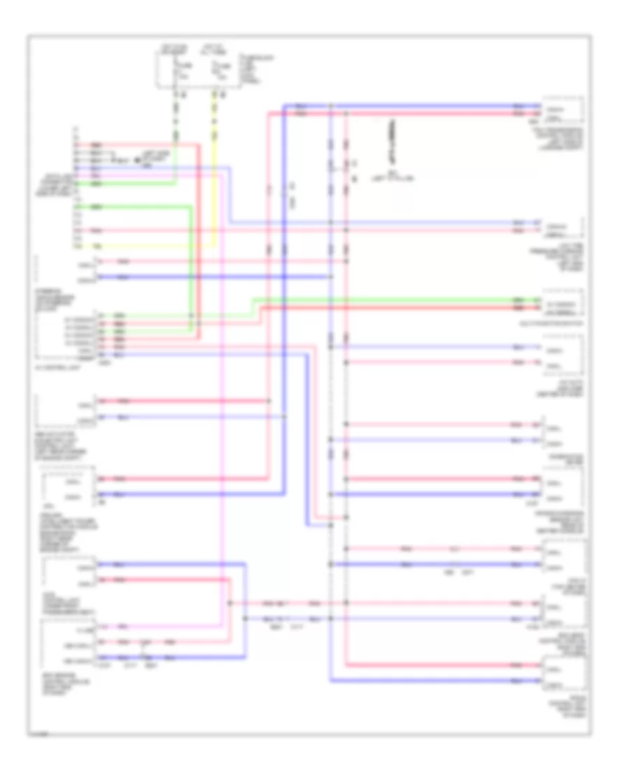
Computer Data Lines Wiring Diagram for Nissan GT-R Premium 2014
 https://portal-diagnostov.com/license.html
Automotive Electricians Portal FZCO
Automotive Electricians Portal FZCO
https://portal-diagnostov.com/license.html
https://portal-diagnostov.com/license.html
Automotive Electricians Portal FZCO
Automotive Electricians Portal FZCOList of elements for Computer Data Lines Wiring Diagram for Nissan GT-R Premium 2014:
- (left side of dash) m55
- A/c auto amplifier (center of dash)
- Abs actuator & electric unit (control unit) (left rear corner of engine compt)
- Air bag diagnosis sensor unit (rear of center console)
- Av comm(h)
- Av comm(l)
- Av control unit
- Awd control unit (under front passenger's seat)
- B201
- B31 (left "c" pillar)
- B45
- Bcm (body control module) (right end of dash)
- Can i/f (top center of dash)
- Can+(h)
- Can+h
- Can-(l)
- Can-h
- Can-l
- Combination meter
- Cpu
- Data link connector (lower left side of dash)
- E-sus control unit (right end of dash)
- E104
- Ecm (engine control module) (right end of dash)
- Fuse 10a
- Fuse block (j/b) (left kick panel)
- Hot at all times
- Hot in on or start
- Ipdm e/r (intelligent power distribution module engine room) (right rear corner of engine compt)
- K line
- Low tire pressure warning control unit (left end of dash)
- M107
- M117
- M122
- M157
- M203
- M271
- M92
- Multi-function switch
- Pnk
- Red
- Shield
- Steering angle sensor (on steering column)
- Tcm (transmission control module) (left side of luggage compt)
- Veh can-h1
- Veh can-l1
COOLING FAN
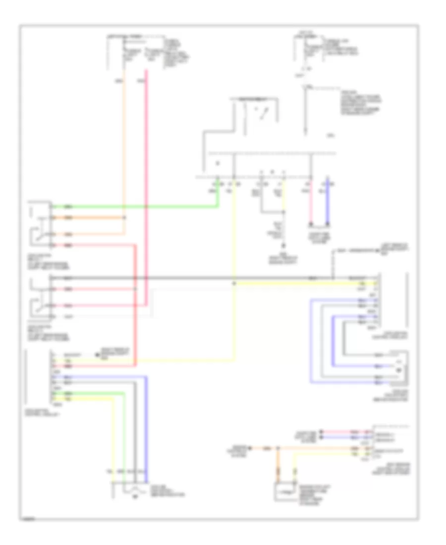
Cooling Fan Wiring Diagram for Nissan GT-R Premium 2014
 https://portal-diagnostov.com/license.html
Automotive Electricians Portal FZCO
Automotive Electricians Portal FZCO
https://portal-diagnostov.com/license.html
https://portal-diagnostov.com/license.html
Automotive Electricians Portal FZCO
Automotive Electricians Portal FZCOList of elements for Cooling Fan Wiring Diagram for Nissan GT-R Premium 2014:
- (left rear of engine compt) e20
- (right rear of engine compt) e46
- Computer data lines system
- Cooling fan control module 1
- Cooling fan control module 2
- Cooling fan motor 1 (behind radiator)
- Cooling fan motor 2 (behind radiator)
- Cooling fan relay 1 (in left rear engine compt relay holder)
- Cooling fan relay 2 (in left rear engine compt relay holder)
- Cpu
- E301
- E302
- E303
- E304
- E35
- E37
- E46 (right rear of engine compt)
- Ecm (engine control module) (right end of dash)
- Engine controls system
- Engine coolant temperature sensor (right rear of engine)
- F101
- Fuse & fusible link & relay box (on battery positive (+) post)
- Fusible link c 80a
- Fusible link f 50a
- Fusible link holder (on fuse/fusible link & relay box)
- Fusible link m 50a
- Gnda-tw/to/tf
- Hot at all times
- Ignition relay
- Ipdm e/r (intelligent power distribution module engine room) (right rear corner of engine compt)
- M107
- Pnk
- Red
- Vehcan-h1
- Vehcan-l1
CRUISE CONTROL
Cruise Control Wiring Diagram for Nissan GT-R Premium 2014
 https://portal-diagnostov.com/license.html
Automotive Electricians Portal FZCO
Automotive Electricians Portal FZCO
https://portal-diagnostov.com/license.html
https://portal-diagnostov.com/license.html
Automotive Electricians Portal FZCO
Automotive Electricians Portal FZCOList of elements for Cruise Control Wiring Diagram for Nissan GT-R Premium 2014:
- (left "c" pillar) b31
- (left side of luggage compt) tcm (transmission control module)
- (right front of engine compt) refrigerant pressure sensor
- (right side of dash) m95
- Accelerator pedal position sensor (top of accelerator pedal assembly)
- Aps1
- Aps2
- Ascd brake switch (on brake pedal bracket)
- Ascd steering switch
- Ascd sw
- Avcc2-aps2
- B45
- B47
- Brk sw
- Can-h
- Can-l
- Cancel switch
- Close
- Combination meter
- Computer data lines system
- Cruise ind
- E103
- E106
- Ecm (engine control module) (right end of dash)
- Electric throttle control actuator (bank 1) (top of right cylinder bank)
- Electric throttle control actuator (bank 2) (top of left cylinder bank)
- Engine controls system
- F101
- F102
- F103
- Fuse 10a
- Fuse block (j/b) (left kick panel)
- Gnd
- Gnda-aps1
- Gnda-aps2
- Hot at all times
- Hot in on or start
- M107
- M11 (left end of dash)
- M116
- M303
- M36
- M95 (right side of dash)
- Main (on/off) switch
- Mtr cls
- Mtr-b2
- Mtr1-b1
- Mtr2-b1
- Nca
- Open
- Output shaft speed sensor
- Pnk
- Pwr sply
- Red
- Resume/ accelerate switch
- Sens (+)
- Sens (-)
- Sens gnd
- Sens pwr sply
- Sens sig
- Sensor 1
- Sensor 2
- Set ind
- Set/coast switch
- Spiral cable (combination switch) (in steering column)
- Stop lp sw
- Stop lp sw sig
- Stoplight switch (on brake pedal bracket)
- Throttle control motor
- Throttle position sensor
- Tps1-b1
- Tps1-b2
- Tps2-b1
- Tps2-b2
- Transmission unit (on transmission)
- Vehcan-h1
- Vehcan-l1
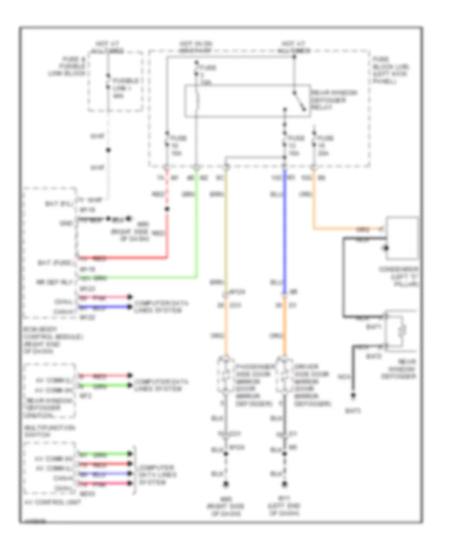
DEFOGGERS
Defoggers Wiring Diagram for Nissan GT-R Premium 2014
 https://portal-diagnostov.com/license.html
Automotive Electricians Portal FZCO
Automotive Electricians Portal FZCO
https://portal-diagnostov.com/license.html
https://portal-diagnostov.com/license.html
Automotive Electricians Portal FZCO
Automotive Electricians Portal FZCOList of elements for Defoggers Wiring Diagram for Nissan GT-R Premium 2014:
- 10g b6
- 4b m2
- 7a m1
- Av comm (h)
- Av comm (l)
- Av control unit
- B471
- B472
- B473
- Bat (f/l)
- Bat (fuse)
- Bcm (body control module) (right end of dash)
- Can-h
- Can-l
- Computer data lines system
- Condenser (left "c" pillar)
- D31
- Driver side door mirror (door mirror defogger)
- Fuse & fusible link block
- Fuse 10a
- Fuse 20a
- Fuse block (j/b) (left kick panel)
- Fusible link i 40a
- Gnd
- Hot at all times
- Hot in on or start
- M11 (left end of dash)
- M118
- M119
- M122
- M123
- M124
- M203
- M3 10c
- M72
- M95 (right side of dash)
- Multifunction switch
- Nca
- Passenger side door mirror (door mirror defogger)
- Pnk
- Rear window defogger
- Rear window defogger relay
- Rear window defogger switch
- Red
- Rr def rly
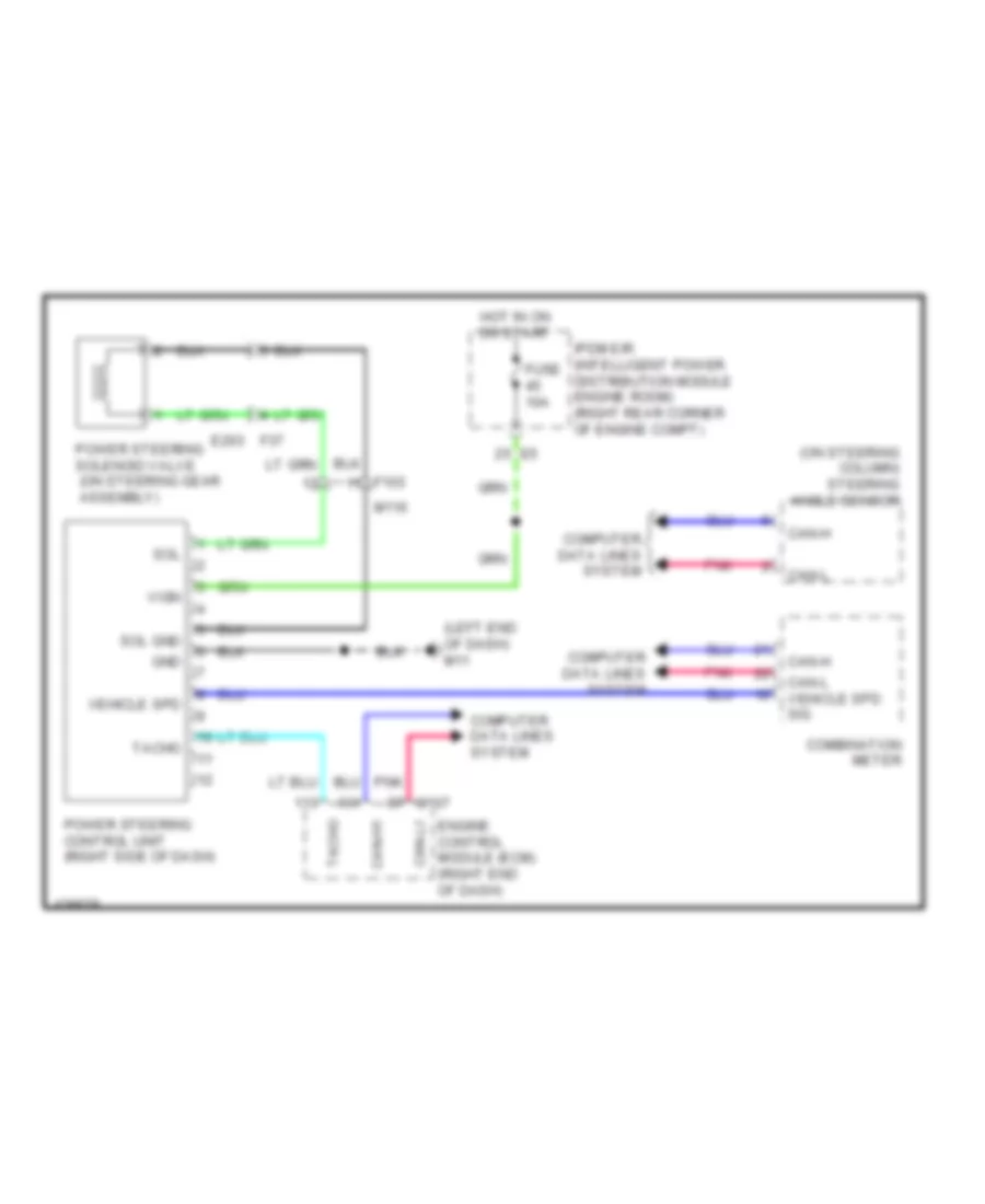
ELECTRONIC POWER STEERING
Electronic Power Steering Wiring Diagram for Nissan GT-R Premium 2014
 https://portal-diagnostov.com/license.html
Automotive Electricians Portal FZCO
Automotive Electricians Portal FZCO
https://portal-diagnostov.com/license.html
https://portal-diagnostov.com/license.html
Automotive Electricians Portal FZCO
Automotive Electricians Portal FZCOList of elements for Electronic Power Steering Wiring Diagram for Nissan GT-R Premium 2014:
- (left end of dash) m11
- (on steering column) steering angle sensor
- Can-h
- Can-h1
- Can-l
- Can-l vehicle spd sig
- Can-l1
- Combination meter
- Computer data lines system
- Engine control module (ecm) (right end of dash)
- F103
- F37 e203
- Fuse 10a
- Gnd
- Hot in on or start
- Ipdm e/r (intelligent power distribution module engine room) (right rear corner of engine compt)
- M107
- M116
- Pnk
- Power steering control unit (right side of dash)
- Power steering solenoid valve (on steering gear assembly)
- Sol
- Sol gnd
- Tacho
- Vehicle spd
- Vign
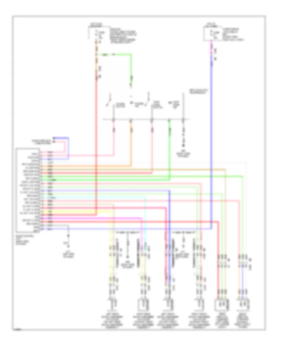
ELECTRONIC SUSPENSION
Electronic Suspension Wiring Diagram for Nissan GT-R Premium 2014
 https://portal-diagnostov.com/license.html
Automotive Electricians Portal FZCO
Automotive Electricians Portal FZCO
https://portal-diagnostov.com/license.html
https://portal-diagnostov.com/license.html
Automotive Electricians Portal FZCO
Automotive Electricians Portal FZCOList of elements for Electronic Suspension Wiring Diagram for Nissan GT-R Premium 2014:
- Act low sig
- B228 b301
- B28 b101
- Bat
- Can-h
- Can-l
- Comf lamp sig
- Comf mode ind
- Comf mode switch
- Comf sw sig
- Computer data lines system
- E-sus control unit (right end of dash)
- E106
- E131
- E133
- E21
- E48
- Fl act hi sig
- Fl act low sig
- Fr act hi sig
- Fr act low sig
- Front vertical g sensor (on right front strut tower)
- Frt g sns sig
- Frt g sns+
- Frt g sns-
- Fuse 10a
- Fuse 15a
- Fuse/fusible link & relay box (on battery positive (+) post)
- Gnd
- Hi sig
- Hot at all times
- Hot in on or start
- Ign
- Ipdm e/r (intelligent power distribution module engine room) (right rear corner of engine compt)
- Left front shock absorber actuator (on left front shock absorber assembly)
- Left rear shock absorber actuator (on left rear shock absorber assembly)
- Low sig
- M11 (left end of dash)
- M117 b201
- M6 e106
- M7 b1
- M95 (right side of dash)
- Nca
- Pnk
- R lamp sig
- R mode ind
- R mode switch
- R sw sig
- Rear vertical g sensor (left side of luggage compt)
- Red
- Right front shock absorber actuator (on right front shock absorber assembly)
- Right rear shock absorber actuator (on right rear shock absorber assembly)
- Rl act hi sig
- Rl act low sig
- Rr act hi sig
- Rr g sns sig
- Rr g sns+
- Rr g sns-
- Set-up switch (suspension)
- Shield
- Sns +
- Sns -
- Sns sig
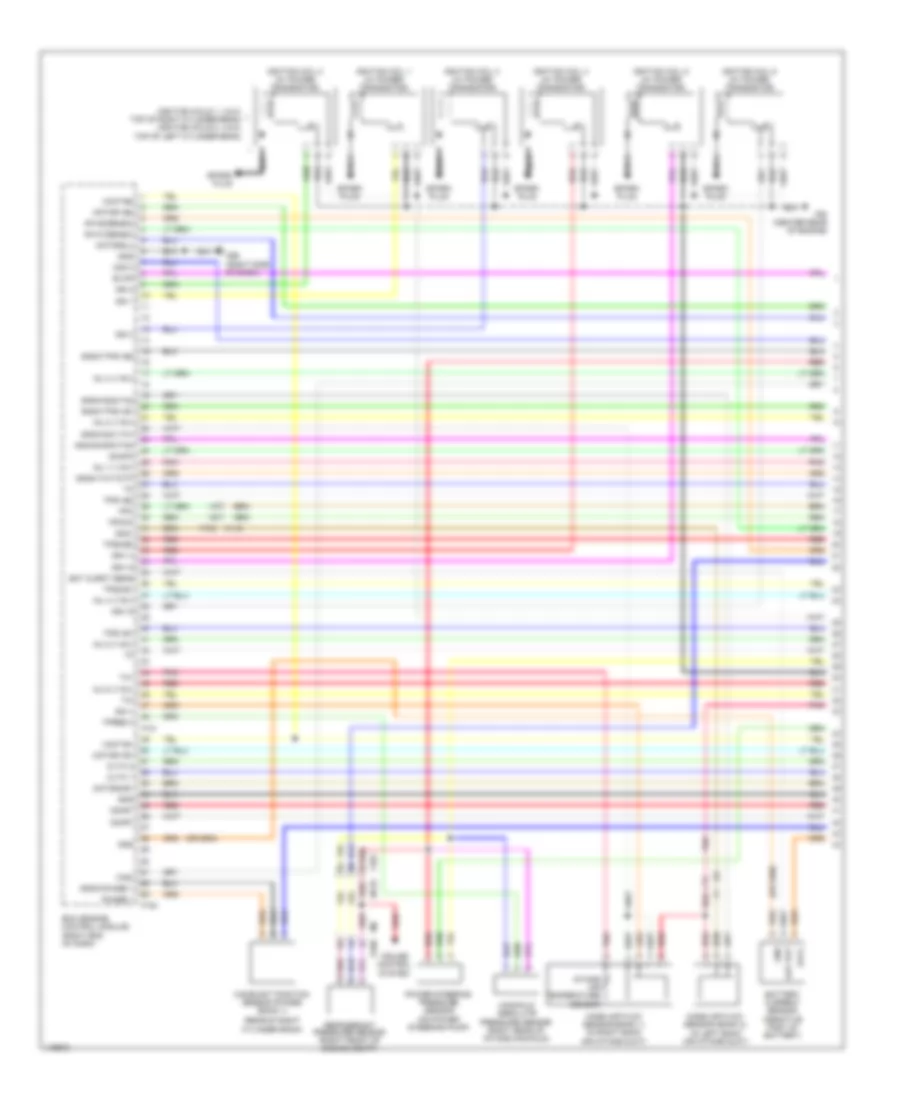
ENGINE PERFORMANCE
3.8L TURBO
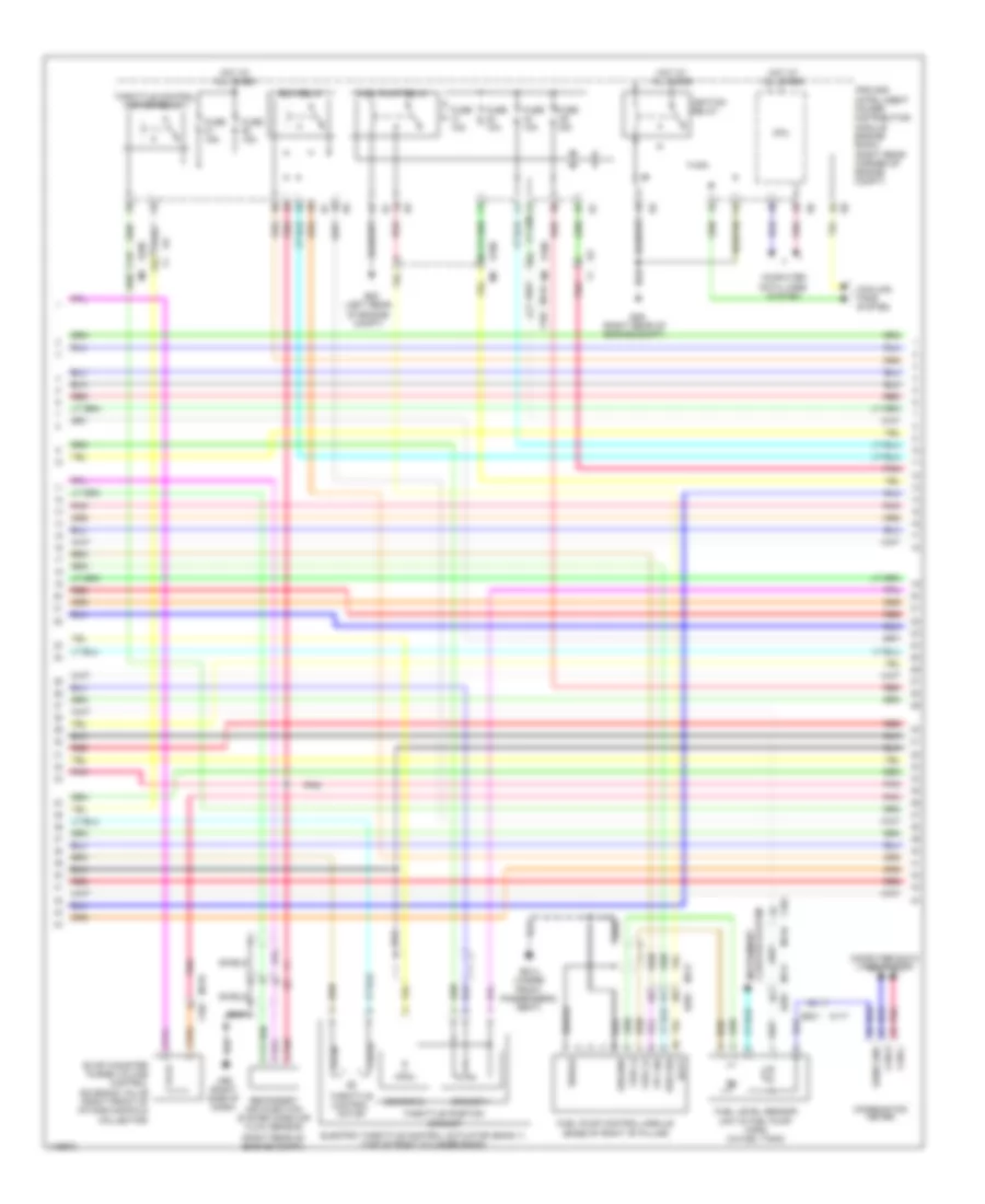
3.8L Turbo, Engine Performance Wiring Diagram (1 of 5) for Nissan GT-R Premium 2014
 https://portal-diagnostov.com/license.html
Automotive Electricians Portal FZCO
Automotive Electricians Portal FZCO
https://portal-diagnostov.com/license.html
https://portal-diagnostov.com/license.html
Automotive Electricians Portal FZCO
Automotive Electricians Portal FZCOList of elements for 3.8L Turbo, Engine Performance Wiring Diagram (1 of 5) for Nissan GT-R Premium 2014:
- (ignition coils 1, 3 & 5: top of right cylinder bank) (ignition coils 2, 4 & 6: top of left cylinder bank)
- (rear of right cylinder bank)
- Af-h1(denso)
- Af-h2(denso)
- Avcc
- Bat curnt sens
- Camshaft position sensor (phase) (bank 1)
- Cdcv
- Cruise control system
- Cvtc 1
- Cvtc 2
- E106
- Ecm (engine control module) (right end of dash)
- Evap
- F101
- F102
- F103
- F103 m116
- F50 (center rear of engine)
- Fpc
- Fpcck
- Gnd
- Gnd-saafm/tam
- Gnda-phase 1
- Gnda-qa1/ta1
- Gnda-qa2/ta2
- Gnda-tps1-b1
- Gnda-tps1-b2
- Gnda-tw/to/tf
- Ign 1
- Ign 2
- Ign 3
- Ign-i 4
- Ign-i 5
- Ign-i 6
- Ignition coil 1 (w/ power transistor)
- Ignition coil 2 (w/ power transistor)
- Ignition coil 3 (w/ power transistor)
- Ignition coil 4 (w/ power transistor)
- Ignition coil 5 (w/ power transistor)
- Ignition coil 6 (w/ power transistor)
- Inj 1 (115v)
- Inj 2 (115v)
- Inj 3 (115v)
- Inj 4 (115v)
- Inj 5 (115v)
- Inj 6 (115v)
- Intake air temperature sensor
- M116
- M95 (right side of dash)
- Manifold absolute pressure sensor (right rear of intake manifold)
- Mass air flow sensor (bank 1) (in right bank air intake duct)
- Mass air flow sensor (bank 2) (in left bank air intake duct)
- Motor1-b1
- Motor1-b2
- Motor2(l)
- Motor2-b1
- Nca
- O2hr1
- Out put
- Phase 1
- Pnk
- Power steering pressure sensor (on power steering pump)
- Qa1+
- Qa2+
- Red
- Refrigerant pressure sensor (right front of engine compt)
- Saafm
- Spark plug
- Ta1
- Tpres 3
- Tps1-b1
- Tps1-b2
- Tps2-b1
- Tps2-b2
- Vmot-b1
- Vmot-b2
- Wgc
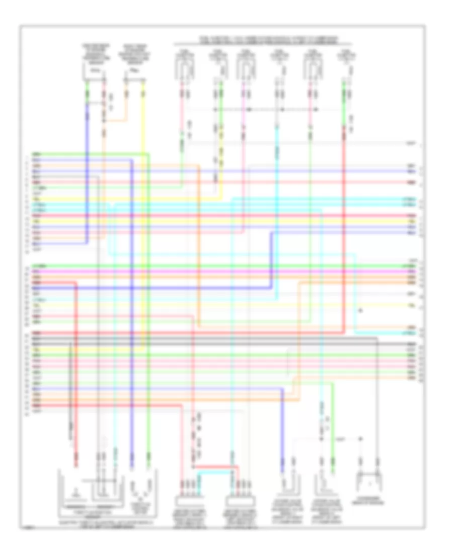
3.8L Turbo, Engine Performance Wiring Diagram (2 of 5) for Nissan GT-R Premium 2014
 https://portal-diagnostov.com/license.html
Automotive Electricians Portal FZCO
Automotive Electricians Portal FZCO
https://portal-diagnostov.com/license.html
https://portal-diagnostov.com/license.html
Automotive Electricians Portal FZCO
Automotive Electricians Portal FZCOList of elements for 3.8L Turbo, Engine Performance Wiring Diagram (2 of 5) for Nissan GT-R Premium 2014:
- (left rear of engine compt)
- (right rear of engine compt)
- B201
- B214 (under front passenger's seat)
- Batt
- Can-h
- Can-l
- Close
- Cluster system instrument
- Combination meter
- Computer data lines system
- Cooling fans system
- Cpu
- Diag sig
- E106
- E106 m6
- E20
- E3 f1
- E46
- Ecm relay
- Electric throttle control actuator (bank 1) (top of right cylinder bank)
- Evap canister purge volume control solenoid valve (right front of intake manifold collector)
- F1 e3
- F103
- Fpc sig
- Fuel (+)
- Fuel (-)
- Fuel level sensor unit & fuel pump (main) (in fuel tank)
- Fuel pump control module (base of right "b" pillar)
- Fuel pump relay
- Fuse 10a
- Fuse 15a
- Ground
- Hot at all times
- Ignition relay
- Ipdm e/r (intelligent power distribution module engine room) (right rear corner of engine compt)
- M116
- M116 f103
- M117
- M117 b201
- M95 (right side of dash)
- Open
- Pnk
- Red
- Secondary air injection system mass air flow sensor
- Sens gnd
- Sensor 1
- Sensor 2
- Sheild
- Shield
- Throttle control motor
- Throttle control motor relay
- Throttle position sensor
3.8L Turbo, Engine Performance Wiring Diagram (3 of 5) for Nissan GT-R Premium 2014
 https://portal-diagnostov.com/license.html
Automotive Electricians Portal FZCO
Automotive Electricians Portal FZCO
https://portal-diagnostov.com/license.html
https://portal-diagnostov.com/license.html
Automotive Electricians Portal FZCO
Automotive Electricians Portal FZCOList of elements for 3.8L Turbo, Engine Performance Wiring Diagram (3 of 5) for Nissan GT-R Premium 2014:
- (center rear of engine) engine oil temperature sensor
- (fuel injector 1, 3 & 5: under intake manifold, in right cylinder bank) (fuel injector 2, 4 & 6: under intake manifold, in left cylinder bank)
- (right rear of engine) engine coolant temperature sensor
- Close
- Condenser (rear of engine)
- E106
- Electric throttle control actuator (bank 2) (top of left cylinder bank)
- F120 f48
- F201 f47
- Fuel injector
- Heated oxygen sensor 2 (bank 1) (right exhaust, upstream of 3 way catalyst 2)
- Heated oxygen sensor 2 (bank 2) (left exhaust, upstream of 3 way catalyst 2)
- Intake valve timing control solenoid valve (bank 1) (front of right cylinder bank)
- Intake valve timing control solenoid valve (bank 2) (front of left cylinder bank)
- M116 f103
- Open
- Pnk
- Red
- Sensor 1
- Sensor 2
- Throttle control motor
- Throttle position sensor
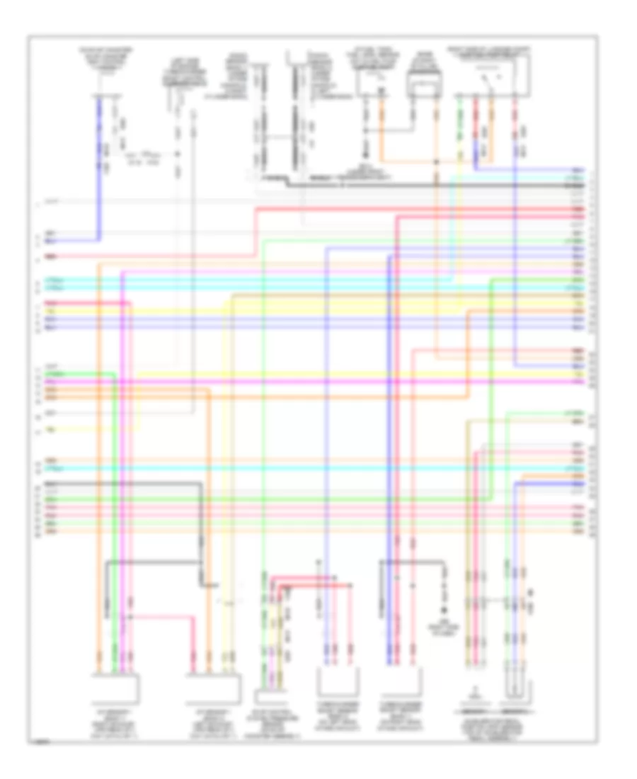
3.8L Turbo, Engine Performance Wiring Diagram (4 of 5) for Nissan GT-R Premium 2014
 https://portal-diagnostov.com/license.html
Automotive Electricians Portal FZCO
Automotive Electricians Portal FZCO
https://portal-diagnostov.com/license.html
https://portal-diagnostov.com/license.html
Automotive Electricians Portal FZCO
Automotive Electricians Portal FZCOList of elements for 3.8L Turbo, Engine Performance Wiring Diagram (4 of 5) for Nissan GT-R Premium 2014:
- (base of right "b" pillar) condenser
- (in fuel tank) fuel level sensor unit & fuel pump (sub fuel pump)
- (left side of engine) turbocharger boost control solenoid valve
- (on evap canister) evap canister vent control valve
- (right side of luggage compt) sub fuel pump relay
- A/f sensor 1 (bank 1) (right exhaust, upstream of 3 way catalyst 1)
- A/f sensor 1 (bank 2) (left exhaust, upstream of 3 way catalyst 1)
- Accelerator pedal position (app) sensor (top of accelerator pedal assembly)
- B201
- B201 m117
- B214 (under front passenger's seat)
- E106
- Evap control system pressure sensor (on evap canister assembly)
- F103
- F201
- F47
- Knock sensor (bank 1) (under intake manifold, in right cylinder bank)
- Knock sensor (bank 2) (under intake manifold, in left cylinder bank)
- M116
- M117
- M95 (right side of dash)
- Pnk
- Red
- Sensor 1
- Sensor 2
- Shield
- Turbocharger boost sensor (bank 1) (on right bank intake air duct)
- Turbocharger boost sensor (bank 2) (on left bank intake air duct)
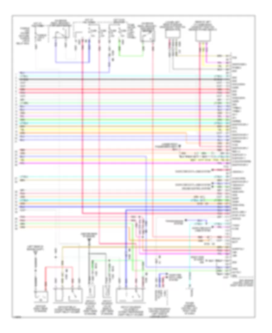
3.8L Turbo, Engine Performance Wiring Diagram (5 of 5) for Nissan GT-R Premium 2014
 https://portal-diagnostov.com/license.html
Automotive Electricians Portal FZCO
Automotive Electricians Portal FZCO
https://portal-diagnostov.com/license.html
https://portal-diagnostov.com/license.html
Automotive Electricians Portal FZCO
Automotive Electricians Portal FZCOList of elements for 3.8L Turbo, Engine Performance Wiring Diagram (5 of 5) for Nissan GT-R Premium 2014:
- (center rear of engine) f49
- (left rear of engine compt) e20
- (lower left rear of engine) crankshaft position sensor (pos)
- (on brake pedal bracket) ascd brake switch
- (on brake pedal bracket) stop light switch
- (rear of left cylinder bank) camshaft position sensor (phase) (bank 2)
- (right side of dash) m95
- (under front passenger's seat) b214
- 02sr2
- 10f
- 15f
- Af+1
- Af+2
- Af-1
- Af-2
- Air cut solenoid valve (bank 1) (right rear of engine)
- Air cut solenoid valve (bank 2) (left rear of engine)
- Air cut solenoid valve relay (in right rear engine compt relay holder)
- Air pump (right rear of engine)
- Air pump relay (in right rear engine compt relay holder)
- Aps1
- Aps2
- Ascdsw
- Avcc
- Avcc2-aps2
- Avcc2-pd/pspre
- B201 m117
- Batt
- Bnc sw
- Can-h
- Can-l
- Computer data lines system
- Cruise control system
- E103
- E106
- E106 m6
- E203
- Ecm (engine control module) (right end of dash)
- F102
- F103
- F37
- Fpr2
- Fuse 10a
- Fuse 15a
- Fuse block (j/b) (left kick panel)
- Fusible link holder (on fuse/ fusible link & relay box)
- Fusible link k 40a
- Gnd
- Gnd-phase 2
- Gnda-aps1
- Gnda-aps2
- Hot at all times
- Hot in on or start
- Ignsw
- Kline
- Knk1(2gain)
- Knk2(2gain)
- M107
- M116
- M6 e106
- Mot rly
- O2sr1
- Pdpres
- Phase 2
- Pnk
- Pnp sig
- Pos
- Power steering control unit (right side of dash)
- Pspres
- Red
- Res 1,2
- Rly sig starter
- Sapmp rly
- Savalverly
- Shield
- Sns pwr sply
- Ssoff
- Stop lp sw
- Sub pump v+
- Sub pump v-
- Tacho
- Tcm (transmission control module) (left side of luggage compt)
- Tpres 1
- Tpres 2
- Transmissions system
- Vbr
- Vehcan-h1
- Vehcan-l1
EXTERIOR LIGHTS
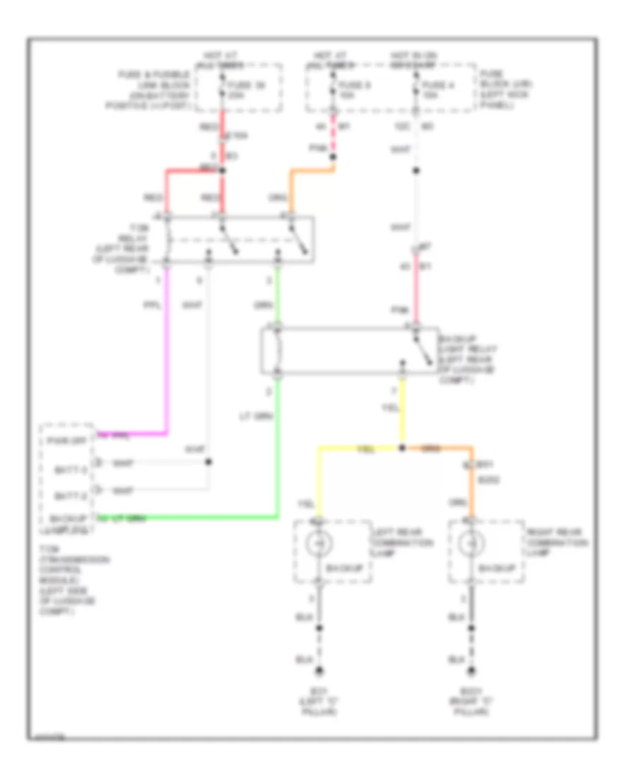
Backup Lamps Wiring Diagram for Nissan GT-R Premium 2014
 https://portal-diagnostov.com/license.html
Automotive Electricians Portal FZCO
Automotive Electricians Portal FZCO
https://portal-diagnostov.com/license.html
https://portal-diagnostov.com/license.html
Automotive Electricians Portal FZCO
Automotive Electricians Portal FZCOList of elements for Backup Lamps Wiring Diagram for Nissan GT-R Premium 2014:
- 12c
- B231 (right "c" pillar)
- B252
- B31 (left "c" pillar)
- B61
- Backup
- Backup lamp sig
- Backup light relay (left rear of luggage compt)
- Batt-2
- Batt-3
- Fuse & fusible link block (on battery positive (+) post)
- Fuse 36 20a
- Fuse 4 10a
- Fuse 9 10a
- Fuse block (j/b) (left kick panel)
- Hot at all times
- Hot in on or start
- Left rear combination lamp
- Pnk
- Pwr off
- Red
- Red e104
- Right rear combination lamp
- Tcm (transmission control module) (left side of luggage compt)
- Tcm relay (left rear of luggage compt)
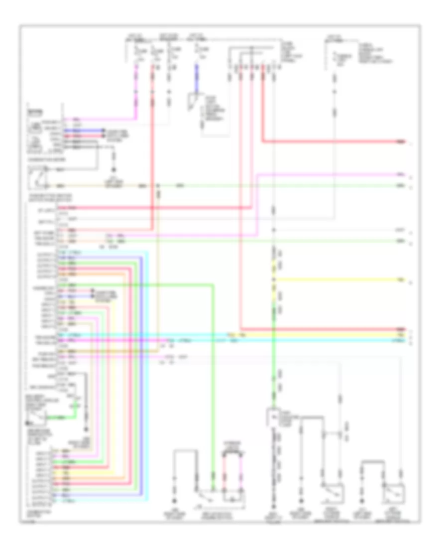
Exterior Lamps Wiring Diagram (1 of 2) for Nissan GT-R Premium 2014
 https://portal-diagnostov.com/license.html
Automotive Electricians Portal FZCO
Automotive Electricians Portal FZCO
https://portal-diagnostov.com/license.html
https://portal-diagnostov.com/license.html
Automotive Electricians Portal FZCO
Automotive Electricians Portal FZCOList of elements for Exterior Lamps Wiring Diagram (1 of 2) for Nissan GT-R Premium 2014:
- 12c
- B201
- B231 (right "c" pillar)
- B239
- B252
- B351
- B353
- B361
- B61
- Bat (f/l)
- Bat (fuse)
- Bcm (body control module) (right end of dash)
- Buzzer
- Can-h
- Can-l
- Combination meter
- Combination switch
- Computer data lines system
- D31
- Driver side door switch (in left "b" pillar)
- Drv door sw
- Drv req sw
- E103
- E106
- Fuse & fusible link block (on battery positive (+) post)
- Fuse 10a
- Fuse block (j/b) (left kick panel)
- Fusible link i 40a
- Gnd
- Hazard sw
- High mounted stop lamp
- Hot at all times
- Hot in on or start
- Ign sply
- Iil gnd
- Input 1
- Input 2
- Input 3
- Input 4
- Input 5
- Interior lights system
- Left outside handle (request switch)
- M11 (left end of dash)
- M112
- M117
- M118
- M119
- M120
- M122
- M123
- M124
- M95 (right side of dash)
- Output 1
- Output 2
- Output 3
- Output 4
- Output 5
- Pas req sw
- Pnk
- Push sw
- Push-button ignition switch (push switch)
- Pwr sply
- Red
- Right outside handle (request switch)
- Set-up switch (hazard switch)
- St lmp 2
- Stop light switch (on brake pedal bracket)
- Tail lamp ind
- Trn sig lf
- Trn sig lr
- Trn sig rf
- Trn sig rr
- Turn ind
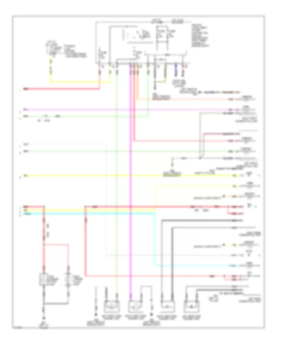
Exterior Lamps Wiring Diagram (2 of 2) for Nissan GT-R Premium 2014
 https://portal-diagnostov.com/license.html
Automotive Electricians Portal FZCO
Automotive Electricians Portal FZCO
https://portal-diagnostov.com/license.html
https://portal-diagnostov.com/license.html
Automotive Electricians Portal FZCO
Automotive Electricians Portal FZCOList of elements for Exterior Lamps Wiring Diagram (2 of 2) for Nissan GT-R Premium 2014:
- (left rear of engine compt) e20
- (right rear of engine compt)
- B155
- B231 (right "c" pillar)
- B252
- B31 (left "c" pillar)
- B61
- B68
- Backup
- Backup lamps circuit
- Computer data lines system
- Cpu
- E106
- E20 (left rear of engine compt)
- E46
- E46 (right rear of engine compt)
- Fuse 10a
- Fuse 15a
- Fusible link d 60a e2
- Fusible link holder (on fuse/fusible link & relay box)
- Hot at all times
- Hot in on or start
- Ipdm e/r (intelligent power distribution module engine room) (right rear corner of engine compt)
- Left front combination lamp
- Left front side marker lamp
- Left license plate lamp
- Left rear combination lamp
- Left rear side marker lamp
- Nca
- Parking
- Pnk
- Red
- Right front combination lamp
- Right front side marker lamp
- Right license plate lamp
- Right rear combination lamp
- Right rear side marker lamp
- Stop
- Tail
- Tail lamp relay
- Turn
- Turn sig
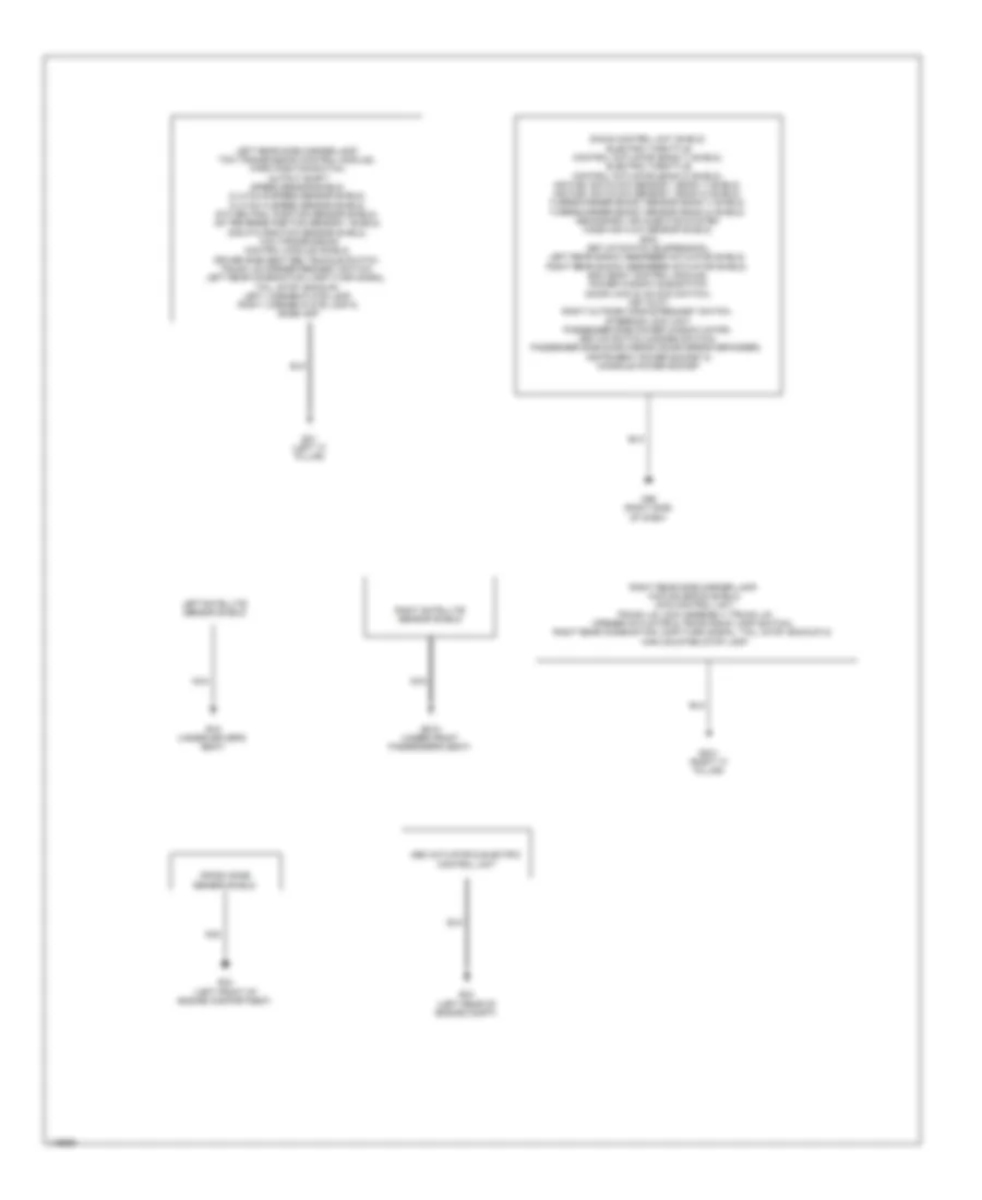
GROUND DISTRIBUTION
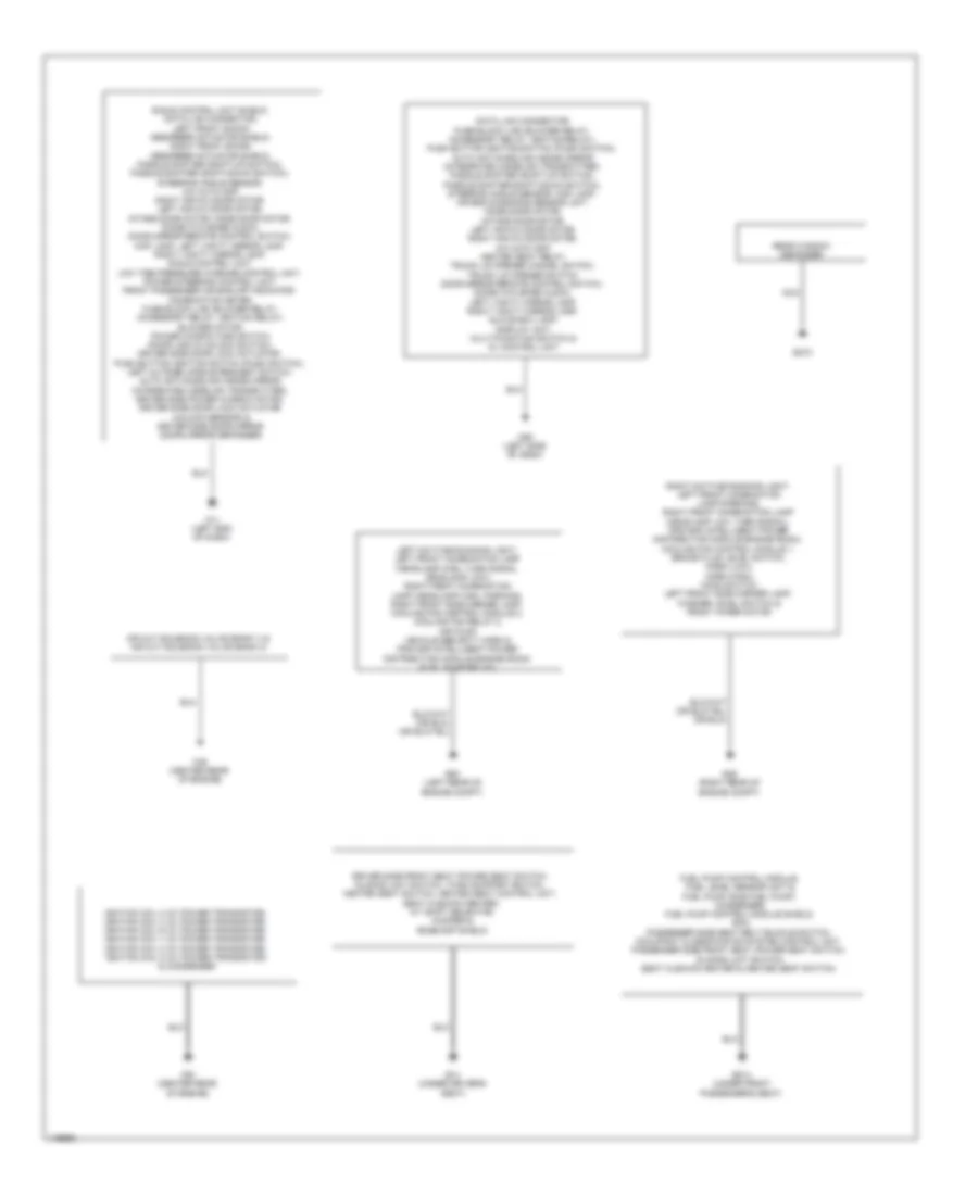
Ground Distribution Wiring Diagram (1 of 2) for Nissan GT-R Premium 2014
 https://portal-diagnostov.com/license.html
Automotive Electricians Portal FZCO
Automotive Electricians Portal FZCO
https://portal-diagnostov.com/license.html
https://portal-diagnostov.com/license.html
Automotive Electricians Portal FZCO
Automotive Electricians Portal FZCOList of elements for Ground Distribution Wiring Diagram (1 of 2) for Nissan GT-R Premium 2014:
- Air cut solenoid valve (bank 1) & air cut solenoid valve (bank 2)
- B14 (under driver's seat)
- B214 (under front passenger's seat)
- B473
- Data link connector, fuse block (j/b) (blower relay, accessory relay, ignition relay), push button ignition switch (push switch), auto anti-dazzling inside mirror (integrated homelink transmitter), paddle shifter (shift-up switch), paddle shifter (shift-down switch), steering angle sensor, map lamp, air bag diagnosis sensor unit, mode door motor, intake door motor, left air mix door motor, right air mix door motor, a/c auto amp, heated seat relay, trunk lid opener cancel switch, trunk lid opener switch, door mirror remote control switch, diode (w/o bose audio), left vanity mirror lamp, right vanity mirror lamp, glove box lamp, display unit, multi-function switch & av control unit
- Driver side front seat (power seat switch, sliding limit switch, thigh support switch, heated seat switch, heated seat control unit, seat cushion heater), a/t shift selector, woofer & bose amp shield
- E-sus control unit shield, data link connector, left front shock absorber actuator shield, right front shock absorber actuator shield, paddle shifter (shift-up switch), paddle shifter (shift-down switch), steering angle sensor, a/c auto amp, right air mix door motor, left air mix door motor, intake door motor, mode door motor, diode (w/o bose audio), door mirror remote control switch, map lamp, left vanity mirror lamp, right vanity mirror lamp, e-sus control unit, low tire pressure warning control unit, power steering control unit, front passenger air bag off indicator, combination meter, fuse block (j/b) (blower relay, accessory relay, ignition relay) blower motor, power window main switch (door lock & unlock switch), driver side door lock actuator, push button ignition switch (push switch), left outside handle request switch, auto anti-dazzling inside mirror (integrated homelink transmitter), driver side power window motor, driver side door lock actuator (unlock sensor) & driver side door mirror (door mirror defogger)
- E20 (left rear of engine compt)
- E46 (right rear of engine compt)
- F49 (center rear of engine)
- F50 (center rear of engine)
- Fuel pump control module, fuel level sensor unit & fuel pump (sub fuel pump), condenser, fuel pump control module shield, ecm, passenger side seat belt buckle switch, occupant classification system control unit, passenger side front seat (power seat switch, sliding limit switch, seat cushion heater & heated seat switch)
- Ignition coil 2 (w/ power transistor), ignition coil 4 (w/ power transistor), ignition coil 6 (w/ power transistor), ignition coil 1 (w/ power transistor), ignition coil 3 (w/ power transistor), ignition coil 5 (w/ power transistor) & condenser
- Left daytime running light, left front combination lamp (headlamp high, turn signal, headlamp low), right front combination lamp (headlamp high, parking), right front side marker lamp, cooling fan control module 2, cooling fan relay 2, air pump, vehicle security horn & ipdm e/r (intelligent power distribution module engine room) (fuel pump relay)
- M11 (left end of dash)
- M55 (left side of dash)
- Nca
- Rear window defogger
- Right daytime running light, left front combination lamp (parking), right front combination lamp (headlamp low, turn signal), ipdm e/r (intelligent power distribution module engine room), cooling fan control module 1, brake fluid level switch, horn (low), horn (high), hood switch, left front side marker lamp, washer level switch & front wiper motor
Ground Distribution Wiring Diagram (2 of 2) for Nissan GT-R Premium 2014
 https://portal-diagnostov.com/license.html
Automotive Electricians Portal FZCO
Automotive Electricians Portal FZCO
https://portal-diagnostov.com/license.html
https://portal-diagnostov.com/license.html
Automotive Electricians Portal FZCO
Automotive Electricians Portal FZCOList of elements for Ground Distribution Wiring Diagram (2 of 2) for Nissan GT-R Premium 2014:
- Abs actuator & electric control unit
- B15 (under driver's seat)
- B215 (under front passenger's seat)
- B231 (right "c" pillar)
- B31 (left "c" pillar)
- Crash zone sensor shield
- E-sus control unit shield, electric throttle control actuator (bank 1) shield, electric throttle control actuator (bank 2) shield, air fuel ratio (a/f) sensor 1 (bank 1) shield, air fuel ratio (a/f) sensor 1 (bank 2) shield, turbocharger boost sensor (bank 1) shield, turbocharger boost sensor (bank 2) shield, secondary air injection system mass air flow sensor shield, ecm, set-up switch (suspension), left rear shock absorber actuator shield, right rear shock absorber actuator shield, bcm (body control module), power window sub-switch (door lock & unlock switch), key slot, right outside handle request switch, steering lock unit, passenger side power window motor, set-up switch (hazard switch), passenger side door mirror (door mirror defogger), instrument power socket & console power socket
- E34 (left front of engine compartment)
- E43 (left rear of engine compt)
- Left rear side marker lamp, tcm (transmission control module), park position switch, output shaft speed sensor shield, clutch b speed sensor shield, clutch a speed sensor shield, 6th neutral position sensor shield, 1st reverse position sensor 1 shield, 2nd-4th position sensor shield, tcm (transmission control module) shield, driver side seat belt buckle switch, trunk lid opener request switch, left rear combination lamp (turn signal, tail, stop, backup), left license plate lamp, right license plate lamp & bose amp
- Left satellite sensor shield
- M95 (right side of dash)
- Nca
- Right rear side marker lamp, awd solenoid shield, awd control unit, trunk lid lock assembly (trunk lid opener actuator & trunk room lamp switch), right rear combination lamp (turn signal, tail, stop, backup) & high mounted stop lamp
- Right satellite sensor shield
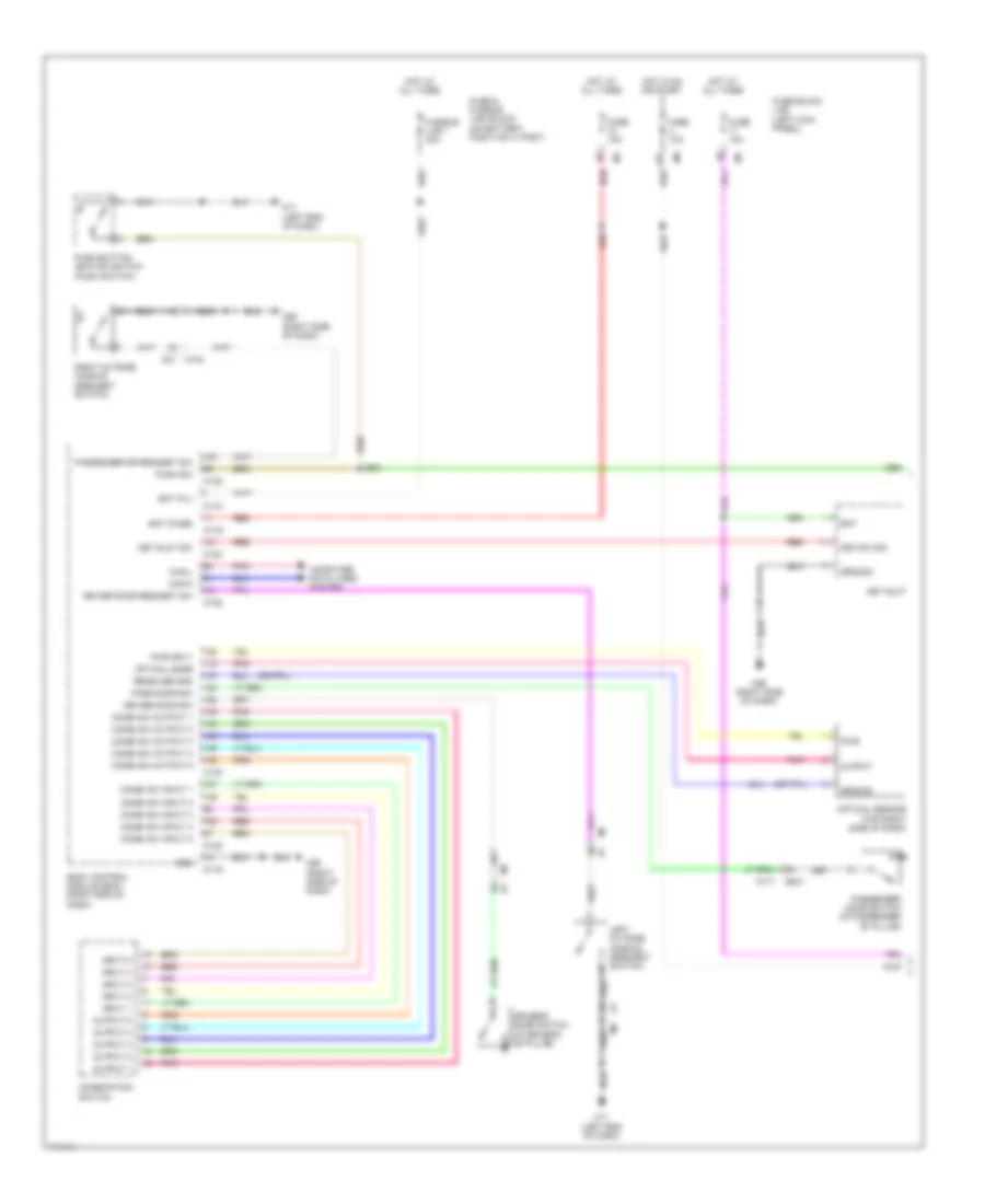
HEADLIGHTS
Headlights Wiring Diagram (1 of 2) for Nissan GT-R Premium 2014
 https://portal-diagnostov.com/license.html
Automotive Electricians Portal FZCO
Automotive Electricians Portal FZCO
https://portal-diagnostov.com/license.html
https://portal-diagnostov.com/license.html
Automotive Electricians Portal FZCO
Automotive Electricians Portal FZCOList of elements for Headlights Wiring Diagram (1 of 2) for Nissan GT-R Premium 2014:
- 12c
- B201
- Bat
- Bat (f/l)
- Bat (fuse)
- Body control module (bcm) (right end of dash)
- Can-h
- Can-l
- Combi sw input 1
- Combi sw input 2
- Combi sw input 3
- Combi sw input 4
- Combi sw input 5
- Combi sw output 1
- Combi sw output 2
- Combi sw output 3
- Combi sw output 4
- Combi sw output 5
- Combination switch
- Computer data lines system
- D31 m124
- Driver door request sw
- Driver door sw
- Driver's door switch (in driver's "b" pillar)
- Fuse & fusible link block (on battery positive (+) post)
- Fuse 10a
- Fuse block (j/b) (left kick panel)
- Fusible link i 40a
- Gnd
- Ground
- Hot at all times
- Hot in on or start
- Input 1
- Input 2
- Input 3
- Input 4
- Input 5
- Key slot
- Key slot sw
- Key sw sig
- Left outside handle (request switch)
- M11 (left end of dash)
- M117
- M118
- M119
- M122
- M123
- M95 (right side of dash)
- Optical sensor (top right side of dash)
- Optical snsr
- Output
- Output 1
- Output 2
- Output 3
- Output 4
- Output 5
- Pass door sw
- Passenger door switch (in passenger "b" pillar)
- Passenger dr request sw
- Pnk
- Push button ignition switch (push switch)
- Push sw
- Pwr
- Pwr sply
- Receiver gnd
- Red
- Right outside handle (request switch)
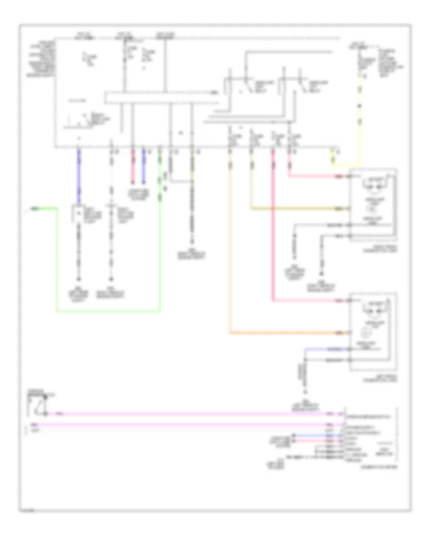
Headlights Wiring Diagram (2 of 2) for Nissan GT-R Premium 2014
 https://portal-diagnostov.com/license.html
Automotive Electricians Portal FZCO
Automotive Electricians Portal FZCO
https://portal-diagnostov.com/license.html
https://portal-diagnostov.com/license.html
Automotive Electricians Portal FZCO
Automotive Electricians Portal FZCOList of elements for Headlights Wiring Diagram (2 of 2) for Nissan GT-R Premium 2014:
- 10a
- 15a
- Can-h
- Can-l
- Combination meter
- Computer data lines system
- Cpu
- E106
- E20 (left rear of engine compt)
- E46 (right rear of engine compt)
- Front fog lamp relay
- Fuse
- Fuse 10a
- Fuse 15a
- Fusible link d 60a
- Fusible link holder (on fuse/ fusible link & relay box)
- Ground
- Headlamp high
- Headlamp high relay
- Headlamp low
- Headlamp low relay
- Hid cont
- High beam ind
- Hot at all times
- Hot in on or start
- Ignition pwr sply
- Ill ground
- Ipdm e/r (intelligent power distribution module engine room) (right rear corner of engine compt)
- Left daytime running light
- Left front combination lamp
- M11 (left end of dash)
- Parking brake switch
- Pnk
- Red
- Right daytime running light
- Right front combination lamp
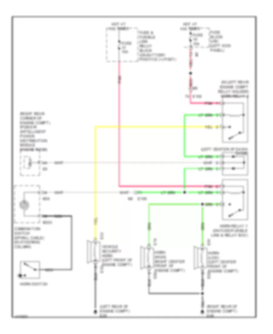
HORN
Horn Wiring Diagram for Nissan GT-R Premium 2014
 https://portal-diagnostov.com/license.html
Automotive Electricians Portal FZCO
Automotive Electricians Portal FZCO
https://portal-diagnostov.com/license.html
https://portal-diagnostov.com/license.html
Automotive Electricians Portal FZCO
Automotive Electricians Portal FZCOList of elements for Horn Wiring Diagram for Nissan GT-R Premium 2014:
- (in left rear
- (left center of dash) diode
- (left rear of engine compt) e20
- (right rear corner of engine compt) ipdm e/r (intelligent power distribution module engine room)
- (right rear of engine compt) e46
- Combination switch (spiral cable) (in steering column)
- Cpu
- E106
- E32
- E79
- E81
- Engine compt relay holder) horn relay 2
- Fuse & fusible link relay block (on battery positive (+) post)
- Fuse 10a
- Fuse 15a
- Fuse block (j/b) (left kick panel)
- Horn (high) (right center front of engine compt) e80
- Horn (low) (left center front of engine compt) e82
- Horn relay 1 (on fuse/fusible link & relay box)
- Horn switch
- Hot at all times
- M303
- M36
- Nca
- Pnk
- Red
- Vehicle security horn (left front of engine compt) e33
INSTRUMENT CLUSTER
Instrument Cluster Wiring Diagram for Nissan GT-R Premium 2014
 https://portal-diagnostov.com/license.html
Automotive Electricians Portal FZCO
Automotive Electricians Portal FZCO
https://portal-diagnostov.com/license.html
https://portal-diagnostov.com/license.html
Automotive Electricians Portal FZCO
Automotive Electricians Portal FZCOList of elements for Instrument Cluster Wiring Diagram for Nissan GT-R Premium 2014:
- 12c
- A/c auto amp
- Air bag
- Air conditioning system
- Alternator
- Ambient sens gnd
- Ambient sens sig
- Av control unit
- B1 m7
- B201
- B61 b252
- Batt pwr sply
- Brake fluid level switch (on brake fluid reservoir)
- Brk fluid sw sig
- Can-h
- Can-l
- Combination meter
- Computer data lines system
- Drv seat belt sig
- E106
- E251 e49
- E46 (right rear of engine compt)
- Electronic power steering system
- Enter
- Enter sw sig
- F103
- Fuel level sensor unit & fuel pump (main) (in fuel tank)
- Fuel level sensor unit (sub) (in fuel tank)
- Fuel lvl sens gnd
- Fuel lvl sens sig
- Fuse 10a
- Fuse block (j/b) (left kick panel)
- Gnd
- Hot at all times
- Hot in on or start
- Ign pwr sply
- Ill ctrl
- Ill ctrl sw (+)
- Ill ctrl sw (-)
- Ill gnd
- Illumination control switch
- Interior lights system
- M11 (left end of dash)
- M116
- M117
- M203
- Meter control switch
- Meter ctrl sw gnd
- Oil level sensor (left side of oil pan)
- Oil lvl sens gnd
- Oil lvl sens sig
- Oil press sens gnd
- Oil press sens pwr
- Oil press sens sig
- Oil pressure
- Park brk sw sig
- Parking brake
- Parking brake switch
- Pnk
- Red
- Seat belt sw sig
- Select
- Select sw sig
- Sensor
- Sound systems
- Starting/charging system
- Trip a/b reset sw
- Trip a/b reset switch
- Trip computer switch
- Veh spd sens sig
- Warning systems
- Washer lvl sw sig
- Wiper/washer system
INTERIOR LIGHTS
Courtesy Lamps Wiring Diagram for Nissan GT-R Premium 2014
 https://portal-diagnostov.com/license.html
Automotive Electricians Portal FZCO
Automotive Electricians Portal FZCO
https://portal-diagnostov.com/license.html
https://portal-diagnostov.com/license.html
Automotive Electricians Portal FZCO
Automotive Electricians Portal FZCOList of elements for Courtesy Lamps Wiring Diagram for Nissan GT-R Premium 2014:
- (center rear of luggage compt lid)
- (right side of dash) m95
- B201
- B231 (right "c" pillar)
- B239
- B351
- Bat (f/l)
- Bat (fuse)
- Body control module (right end of dash)
- Can-h
- Can-l
- Computer data lines system
- D1 m5
- D12
- D21
- D31
- D31 m124
- D42
- D51
- Door
- Dr door unlock sens
- Driver door sw
- Driver door switch (in left "b" pillar)
- Driver dr request sw
- Driver side door lock actuator (unlock sensor) (rear of driver's door)
- Driver side step lamp
- Fuse & fusible link block (on battery positive (+) post)
- Fuse 10a
- Fuse block (j/b) (left kick panel)
- Fusible link i 40a
- Gnd
- Hot at all times
- Left outside handle (request switch)
- Left vanity
- M11 (left end of dash)
- M117
- M118
- M119
- M120
- M121
- M122
- M123
- M124
- M55 (left side of dash)
- M95 (right side of dash)
- Map lamp
- Mirror lamp
- Off
- Pass dr request sw
- Passenger door sw
- Passenger door switch (in right "b" pillar)
- Passenger side step lamp
- Pnk
- Push button ignition switch
- Push sw
- Push switch
- Red
- Right outside handle (request switch)
- Right vanity mirror lamp
- Room lamp timer ctrl
- Step lamp
- Trunk lid lock assembly (trunk room lamp switch)
- Trunk room lamp
- Trunk room lamp sw
- Trunk room lp output
Instrument Illumination Wiring Diagram for Nissan GT-R Premium 2014
 https://portal-diagnostov.com/license.html
Automotive Electricians Portal FZCO
Automotive Electricians Portal FZCO
https://portal-diagnostov.com/license.html
https://portal-diagnostov.com/license.html
Automotive Electricians Portal FZCO
Automotive Electricians Portal FZCOList of elements for Instrument Illumination Wiring Diagram for Nissan GT-R Premium 2014:
- (left side of dash)
- (or red)
- 12c
- A/t shift selector (base of a/t shift lever assembly)
- Av control unit
- B10
- B201
- B210 b551
- B252
- B501
- B501 b10
- B551 b210
- B61
- Bat (f/l)
- Bat (fuse)
- Body control module (right end of dash)
- Can-h
- Can-l
- Comb sw input 1
- Comb sw input 2
- Comb sw input 3
- Comb sw input 4
- Comb sw input 5
- Comb sw output 1
- Comb sw output 2
- Comb sw output 3
- Comb sw output 4
- Comb sw output 5
- Combination meter
- Combination switch
- Combination switch (spiral cable) (in steering column)
- Computer data lines system
- Console power socket
- Cpu
- Diode (left center of dash)
- Door mirror remote control switch
- Driver side front seat (w/ heated seat)
- E103
- E46 (right rear of engine compt)
- Fuse & fusible link block (on battery positive (+) post)
- Fuse 10a
- Fuse 15a
- Fuse block (j/b) (left kick panel)
- Fuse block (j/b) (left kick panel) m2
- Fusible link d 60a
- Fusible link holder (on fuse/ fusible link & relay box)
- Fusible link i 40a
- Glove box lamp
- Gnd
- Heated seat switch
- Hot at all times
- Hot in on or start
- Ill
- Ill cont pnk
- Illumination control switch
- Input 1
- Input 2
- Input 3
- Input 4
- Input 5
- Ipdm e/r (intelligent power distribution module engine room) (right rear corner of engine compt)
- M11 (left end of dash)
- M117
- M118
- M119
- M122
- M123
- M148
- M149
- M203
- M303
- M35
- M36
- M55
- M95 (right side of dash)
- Meter control switch
- Meter illumination
- Multi- function switch
- Nca
- Output 1
- Output 2
- Output 3
- Output 4
- Output 5
- Passenger side front seat (w/ heated seat)
- Pnk
- Push button ignition switch
- Push button sw
- Red
- Set up switch
- Steering switch
- Tail lamp relay
- Trip computer switch
- Trunk lid opener switch
- Unified meter control unit
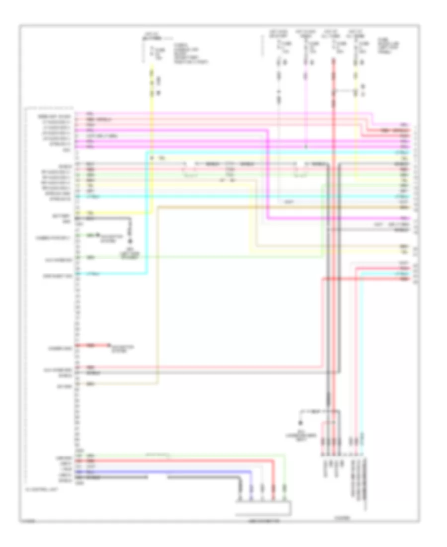
NAVIGATION
Navigation Wiring Diagram, Base (1 of 3) for Nissan GT-R Premium 2014
 https://portal-diagnostov.com/license.html
Automotive Electricians Portal FZCO
Automotive Electricians Portal FZCO
https://portal-diagnostov.com/license.html
https://portal-diagnostov.com/license.html
Automotive Electricians Portal FZCO
Automotive Electricians Portal FZCOList of elements for Navigation Wiring Diagram, Base (1 of 3) for Nissan GT-R Premium 2014:
- (23 to 25 not used)
- (or red)
- (pins: 102 to 103 n0t used)
- (pins: 105 to 116 n0t used)
- (pins: 120 to 128 n0t used)
- (pins: 30 to 41 n0t used)
- (pins: 43 to 45 n0t used)
- (pins: 50 to 60 n0t used)
- (under driver's seat) left audio amplifier
- (under driver's seat) right audio amplifier
- Acc
- Amp on sig
- Audio amp on sig
- Aux image gnd
- Aux image sig
- Aux sound sig gnd
- Auxiliary inputs jacks (option connector)
- Av comm (h)
- Av comm (l)
- Av control unit
- B1 m7
- Battery
- Camera gnd
- Camera pwr sply
- Computer data lines system
- Disk eject sig
- E106
- Fuse & fusible link block (on battery positive (+) post)
- Fuse 10a
- Fuse 15a
- Fuse block (j/b) (left kick panel)
- Gnd
- Hot at all times
- Hot in acc or on
- Left front door speaker
- Left tweeter
- Lf door speaker (+)
- Lf door speaker (-)
- Lf sound sig (+)
- Lf sound sig (-)
- Lh aux sound sig (+)
- Lr sound sig (+)
- Lr sound sig (-)
- Lr speaker (+)
- Lr speaker (-)
- M124 d31
- M201
- M202
- M204
- M205
- M5 d1
- M55 (left side of dash)
- Multi-function switch
- Navigation system
- Pnk
- Red
- Rf door speaker (+)
- Rf door speaker (-)
- Rf sound sig (+)
- Rf sound sig (-)
- Rh aux sound sig (+)
- Right front door speaker
- Right tweeter
- Rr sound sig (+)
- Rr sound sig (-)
- Rr speaker (+)
- Rr speaker (-)
- Shield
- Strg sw a
- Strg sw b
- Strg sw gnd
- Sw gnd
- Usb connector
- Usb d+
- Usb d-
- Usb gnd
- V bus
Navigation Wiring Diagram, Base (2 of 3) for Nissan GT-R Premium 2014
 https://portal-diagnostov.com/license.html
Automotive Electricians Portal FZCO
Automotive Electricians Portal FZCO
https://portal-diagnostov.com/license.html
https://portal-diagnostov.com/license.html
Automotive Electricians Portal FZCO
Automotive Electricians Portal FZCOList of elements for Navigation Wiring Diagram, Base (2 of 3) for Nissan GT-R Premium 2014:
- 10b
- 12c
- Combination switch (spiral cable) (in steering column)
- Fuse 10a
- Fuse 20a
- Fuse block (j/b) (left kick panel)
- Hot at all times
- Hot in on or start
- Interior lights system
- M106
- M140
- M141
- M303
- M36
- M7 b1
- Microphone (center front of roof)
- Microphone gnd
- Microphone sig
- Microphone vcc
- Mrk
- Nca
- Pnk
- Rear speaker
- Seek down
- Seek up
- Shield
- Source sw
- Start/ stop
- Steering switch
- Tel sw
- Volume down
- Volume up
- Vr sw
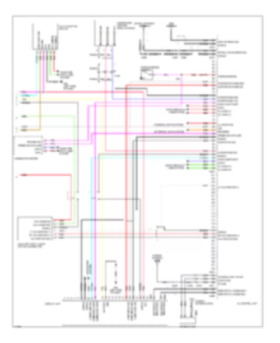
Navigation Wiring Diagram, Base (3 of 3) for Nissan GT-R Premium 2014
 https://portal-diagnostov.com/license.html
Automotive Electricians Portal FZCO
Automotive Electricians Portal FZCO
https://portal-diagnostov.com/license.html
https://portal-diagnostov.com/license.html
Automotive Electricians Portal FZCO
Automotive Electricians Portal FZCOList of elements for Navigation Wiring Diagram, Base (3 of 3) for Nissan GT-R Premium 2014:
- (pins: 61 to 64 n0t used)
- Acc
- Am fm main
- Antenna amp on sig
- Antenna amplifier
- Av comm(h)
- Av comm(l)
- Av control unit
- Batt
- Bcm (body control module) (right end of dash)
- Camera img sig
- Can-h
- Can-l
- Combination meter
- Comm
- Comp syn sig
- Compostion image gnd
- Compostion image sig
- Computer data lines system
- Display unit
- Exterior lights system
- Fm sub
- Gnd
- Gps antenna
- Gps antenna sig
- Ignition
- Ill
- Image gnd
- Image sig
- Image sig(+)
- Image sig(-) rgb digtal
- Interior lights system
- M203
- M371
- M372
- M373
- M375
- M376
- M379
- M381
- M390
- M391
- M392
- M396
- M397
- M55 (left side of dash)
- M93
- Microphone gnd
- Microphone sig
- Microphone vcc
- Navigation
- Nca
- Parking brake
- Parking brake switch
- Pnk
- Prk brk sw
- Red
- Reverse
- Rgb digital image sig(+)
- Rgb digital image sig(-)
- Satellite antenna sig
- Satellite radio antenna
- Shield
- Syn sig
- System
- Vcc (8 pluse)
- Vehicle speed (8-pluse)
- Window antenna (main)
- Window antenna (sub)
Navigation Wiring Diagram, Bose (1 of 3) for Nissan GT-R Premium 2014
 https://portal-diagnostov.com/license.html
Automotive Electricians Portal FZCO
Automotive Electricians Portal FZCO
https://portal-diagnostov.com/license.html
https://portal-diagnostov.com/license.html
Automotive Electricians Portal FZCO
Automotive Electricians Portal FZCOList of elements for Navigation Wiring Diagram, Bose (1 of 3) for Nissan GT-R Premium 2014:
- 10b
- 12c
- Acc
- Aux image gnd
- Aux image sig
- Av control unit
- B14 (under driver's seat)
- Battery
- Bose amp. on sig
- Camera gnd
- Camera pwr sply
- Disk eject sig
- E106
- Fuse & fusible link block (on battery positive (+) post)
- Fuse 10a
- Fuse 15a
- Fuse 20a
- Fuse block (j/b) (left kick panel)
- Gnd
- Hot at all times
- Hot in acc or on
- Hot in on or start
- Lf audio sig (+)
- Lf audio sig (-)
- Lr audio sig (+)
- Lr audio sig (-)
- M201
- M202
- M205
- M55 (left side of dash)
- M7 b1
- Navigation system
- Pnk
- Red
- Rf audio sig (+)
- Rf audio sig (-)
- Rr audio sig (+)
- Rr audio sig (-)
- Shield
- Sound sig woofer (+)
- Sound sig woofer (-)
- Strg sw a
- Strg sw b
- Strg sw gnd
- Sw gnd
- Usb connector
- Usb d+
- Usb d-
- Usb gnd
- V bus
- Woofer
- Woofer amp on sig
Navigation Wiring Diagram, Bose (2 of 3) for Nissan GT-R Premium 2014
 https://portal-diagnostov.com/license.html
Automotive Electricians Portal FZCO
Automotive Electricians Portal FZCO
https://portal-diagnostov.com/license.html
https://portal-diagnostov.com/license.html
Automotive Electricians Portal FZCO
Automotive Electricians Portal FZCOList of elements for Navigation Wiring Diagram, Bose (2 of 3) for Nissan GT-R Premium 2014:
- B16
- B17
- B31 (left "c" pillar)
- Battery
- Bose amp on sig
- Bose amplifier (under driver's seat)
- Center speaker
- Cntr speaker (-)
- Cntr speaker(+)
- Combination switch (spiral cable) (in steering column)
- D12
- D21
- D31
- D42
- D51
- Gnd
- Illum
- Interior lights system
- Left front door speaker
- Left front door squawker
- Left rear speaker
- Left tweeter
- Lf (+)
- Lf (-)
- Lf dr (+)
- Lf dr (-)
- Lf dr squ (+)
- Lf dr squ (-)
- Lr (+)
- Lr (-)
- M124
- M140
- M141
- M303
- M36
- Mrk
- Nca
- Pnk
- Red
- Rf (+)
- Rf (-)
- Rf dr (+)
- Rf dr (-)
- Rf dr squ (+)
- Rf dr squ (-)
- Right front door speaker
- Right front door squawker
- Right rear speaker
- Right tweeter
- Rr (+)
- Rr (-)
- Seek down
- Seek up
- Shield
- Snd sig wfr (+)
- Snd sig wfr (-)
- Source sw
- Start/ stop
- Steering switch
- Tel sw
- Volume down
- Volume up
- Vr sw
- Wfr amp on sig
Navigation Wiring Diagram, Bose (3 of 3) for Nissan GT-R Premium 2014
 https://portal-diagnostov.com/license.html
Automotive Electricians Portal FZCO
Automotive Electricians Portal FZCO
https://portal-diagnostov.com/license.html
https://portal-diagnostov.com/license.html
Automotive Electricians Portal FZCO
Automotive Electricians Portal FZCOList of elements for Navigation Wiring Diagram, Bose (3 of 3) for Nissan GT-R Premium 2014:
- Acc
- Am-fm main
- Antenna amp
- Antenna amp. on sig
- Aux image gnd
- Aux image sig
- Aux snd sig gnd
- Auxiliary input jacks (option connector)
- Av comm (h)
- Av comm (l)
- Av control unit
- Battery
- Camera img sig
- Can-h
- Can-l
- Combination meter
- Comm (cont-disp)
- Comm (disp-cont)
- Comp image gnd
- Comp image sig
- Comp sync sig
- Composite image gnd
- Composite image sig
- Computer data lines system
- Disk eject sig
- Display unit
- Exterior lights system
- Fm sub
- Gnd
- Gps antenna
- Gps antenna sig
- Ign
- Illumination
- Image sig(+) rgb digital
- Interior lights system
- Lh aux snd sig (+)
- Lt aux snd sig (+)
- M106
- M203
- M204
- M371
- M372
- M373
- M375
- M376
- M379
- M381
- M390
- M391
- M392
- M396
- M397 image sig(-) rgb digital
- M55 (left side of dash)
- M93
- Microphone (center front of roof)
- Microphone gnd
- Microphone sig
- Microphone vcc
- Multi-function switch
- Nca
- Parking brake
- Parking brake switch
- Pnk
- Prk brk sw
- Red
- Reverse
- Rgb digital image sig(+)
- Rgb digital image sig(-)
- Rh aux snd sig (+)
- Rt aux snd sig (+)
- Satellite antenna sig
- Satellite radio antenna
- Shield
- Speed sig (8-pulse)
- Sw gnd
- System navigation
- Window antenna (main)
- Window antenna (sub)
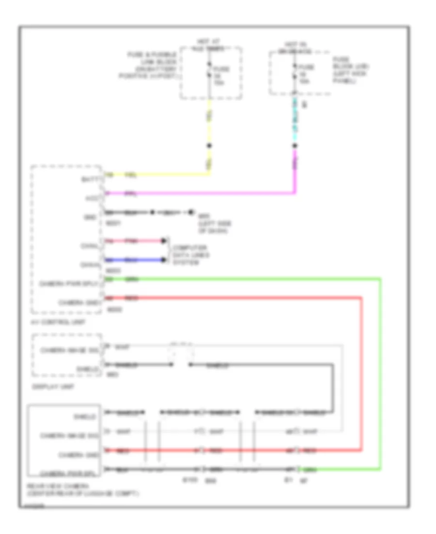
Rear Camera Wiring Diagram for Nissan GT-R Premium 2014
 https://portal-diagnostov.com/license.html
Automotive Electricians Portal FZCO
Automotive Electricians Portal FZCO
https://portal-diagnostov.com/license.html
https://portal-diagnostov.com/license.html
Automotive Electricians Portal FZCO
Automotive Electricians Portal FZCOList of elements for Rear Camera Wiring Diagram for Nissan GT-R Premium 2014:
- Acc
- Av control unit
- B1 m7
- B155 b68
- Batt
- Camera gnd
- Camera image sig
- Camera pwr spl
- Camera pwr sply
- Can-h
- Can-l
- Computer data lines system
- Display unit
- Fuse & fusible link block (on battery positive (+) post)
- Fuse 10a
- Fuse 15a
- Fuse block (j/b) (left kick panel)
- Gnd
- Hot at all times
- Hot in on or acc
- M201
- M202
- M203
- M55 (left side of dash)
- M93
- Pnk
- Rear view camera (center rear of luggage compt)
- Red
- Shield
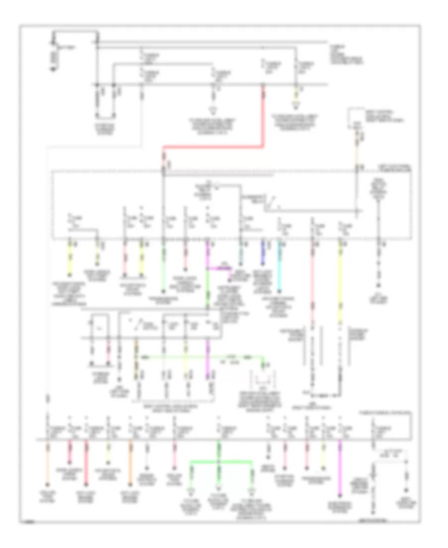
POWER DISTRIBUTION
Power Distribution Wiring Diagram (1 of 3) for Nissan GT-R Premium 2014
 https://portal-diagnostov.com/license.html
Automotive Electricians Portal FZCO
Automotive Electricians Portal FZCO
https://portal-diagnostov.com/license.html
https://portal-diagnostov.com/license.html
Automotive Electricians Portal FZCO
Automotive Electricians Portal FZCOList of elements for Power Distribution Wiring Diagram (1 of 3) for Nissan GT-R Premium 2014:
- (left kick panel) fuse block (j/b)
- 10b
- 11f
- Acc ind
- Acc rly
- Accessory relay
- Air conditioning, door locks, anti-theft, computer data lines & mirrors systems
- Air conditioning, mirrors, navigation & sound systems
- Anti-lock brakes & system exterior lights systems
- Anti-lock brakes system
- Battery
- Body computer system
- Body control module (bcm) (right end of dash)
- Circuit breaker (center of dash)
- Console power socket
- Cooling fans system
- Cpu
- Door locks & anti-theft systems
- Door locks & horns system
- Door locks, horns & body computer systems
- E101
- E103
- E106
- E202
- E252
- Electronic suspension system
- Engine controls
- From ignition relay (diagram 2 of 3)
- Fuse & fusible link block
- Fuse 10a
- Fuse 15a
- Fuse 20a
- Fusible link a 140a
- Fusible link b 100a
- Fusible link c 80a
- Fusible link d 60a
- Fusible link e 80a
- Fusible link f 50a
- Fusible link g 30a
- Fusible link h 40a
- Fusible link holder (on fuse/fusible link & relay box)
- Fusible link i 40a
- Fusible link k 40a
- Fusible link m 50a
- Ill
- Instrument cluster, door locks, anti-theft& cruise control systems
- Instrument power socket
- Interior lights system
- Ipdm e/r (intelligent power distribution module engine room) (right rear corner of engine compt)
- Lock ind
- M1 5a
- M11 (left end of dash)
- M119 acc ind
- M122
- M122 on ind
- M123
- M2 7b
- M55 (left side of dash)
- M95 (right side of dash)
- Navigation & sound
- Navigation & sound systems
- Nca
- On ind
- Pnk
- Push sw
- Push switch
- Push-button ignition switch
- Red
- Seats system
- Starting/ charging system
- System
- Systems
- To blower relay (diagram 2 of 3)
- To fuse block (j/b) (diagram 2 of 3)
- To ipdm e/r (intelligent power distribution module engine room) (diagram 2 of 3)
- To ipdm e/r (intelligent power distribution module engine room) (diagram 3 of 3)
- Transmissions system
Power Distribution Wiring Diagram (2 of 3) for Nissan GT-R Premium 2014
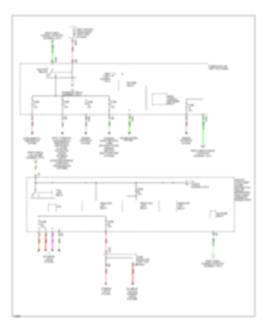 https://portal-diagnostov.com/license.html
Automotive Electricians Portal FZCO
Automotive Electricians Portal FZCO
https://portal-diagnostov.com/license.html
https://portal-diagnostov.com/license.html
Automotive Electricians Portal FZCO
Automotive Electricians Portal FZCOList of elements for Power Distribution Wiring Diagram (2 of 3) for Nissan GT-R Premium 2014:
- 10f
- 11c
- 12c
- 14f
- 15f
- 4g red
- 8b red
- Blower relay
- Body control module (bcm) (right end of dash)
- Cpu
- Cruise control system
- E102
- E103
- Engine controls system
- Exterior lights & interior lights systems
- Exterior lights system
- From fuse & fusible link block (diagram 1 of 3)
- From fusible link holder (diagram 1 of 3)
- From g fuse 7 (diagram 1 of 3)
- Front fog lamp relay
- Fuse 10a
- Fuse 15a
- Fuse block (j/b) (left kick panel)
- Headlamp high relay
- Headlamp low relay
- Ign rly
- Ignition relay
- Interior lights system
- Ipdm e/r (intelligent power distribution module engine room) (right rear corner of engine compt)
- M122
- Pnk
- Rear window defogger relay
- Red
- Starter relay
- Tail- lamp relay
- To accessory relay (diagram 1 of 3)
- To fuse 60 (diagram 3 of 3)
- Warning, computer data lines, air conditioning, mirrors, seats & body computer systems
Power Distribution Wiring Diagram (3 of 3) for Nissan GT-R Premium 2014
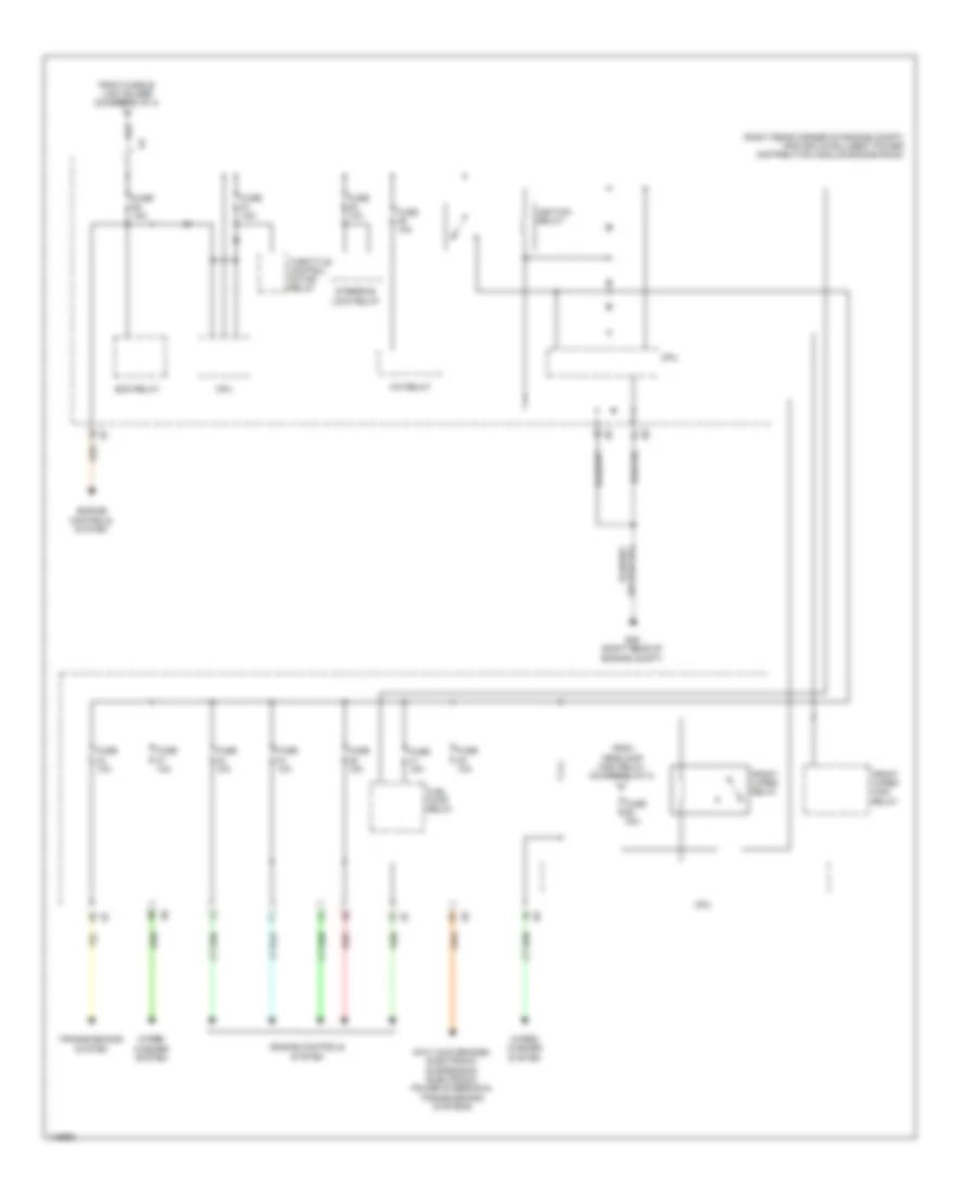 https://portal-diagnostov.com/license.html
Automotive Electricians Portal FZCO
Automotive Electricians Portal FZCO
https://portal-diagnostov.com/license.html
https://portal-diagnostov.com/license.html
Automotive Electricians Portal FZCO
Automotive Electricians Portal FZCOList of elements for Power Distribution Wiring Diagram (3 of 3) for Nissan GT-R Premium 2014:
- (right rear corner of engine compt) ipdm e/r (intelligent power distribution module engine room)
- A/c relay
- Anti-lock brakes, electronic suspension, electronic power steering & transmissions systems
- Cpu
- E46 (right rear of engine compt)
- Ecm relay
- Engine controls system
- From fusible link holder (diagram 1 of 3)
- From headlamp high relay (diagram 2 of 3)
- Front wiper high relay
- Front wiper relay
- Fuel pump relay
- Fuse 10a
- Fuse 15a
- Fuse 30a
- Ignition relay
- Red
- Steering lock relay
- Throttle control motor relay
- Transmissions system
- Wiper/ washer system
POWER DOOR LOCKS
Power Door Locks Wiring Diagram, with Intelligent Key Unit (1 of 3) for Nissan GT-R Premium 2014
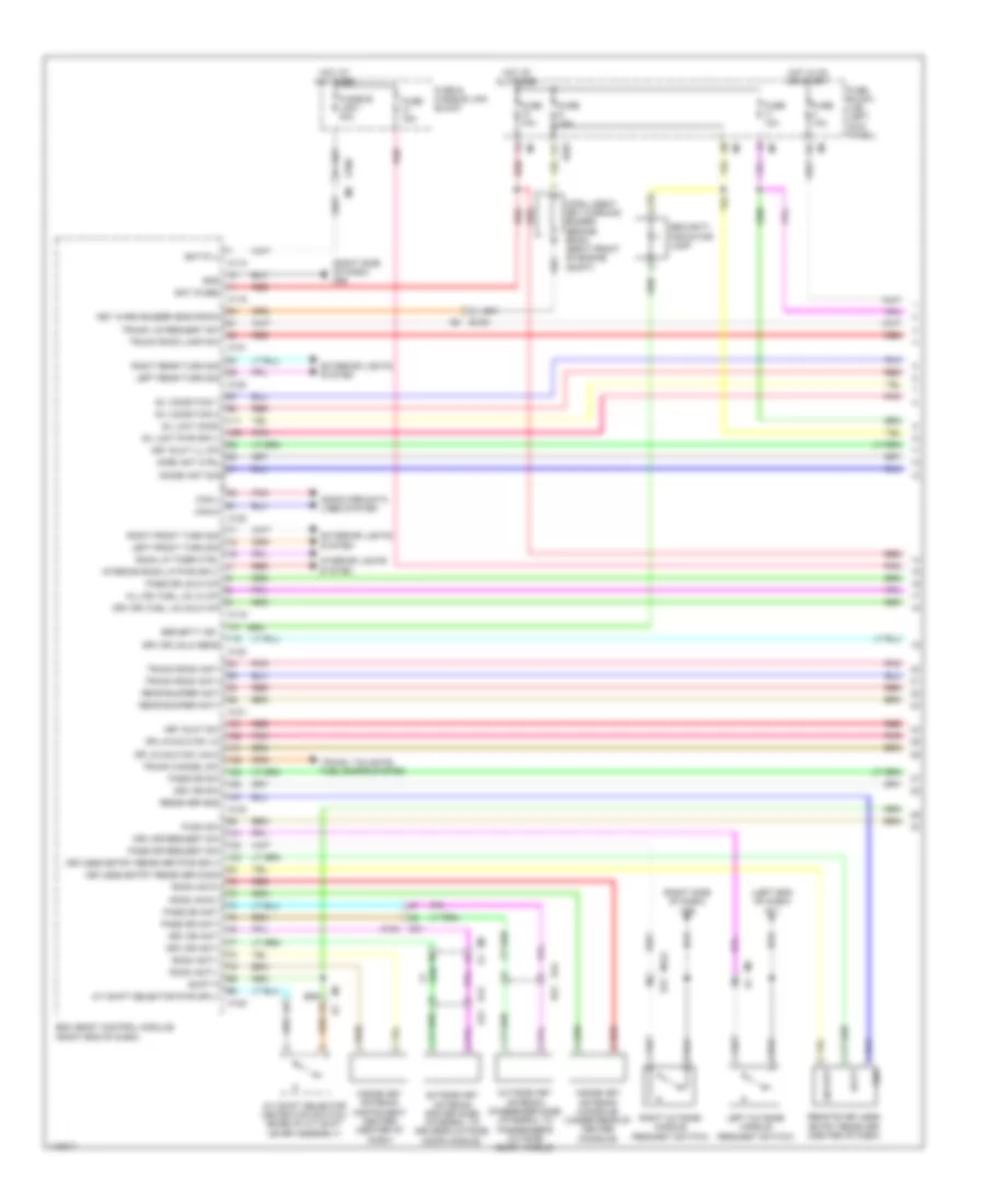 https://portal-diagnostov.com/license.html
Automotive Electricians Portal FZCO
Automotive Electricians Portal FZCO
https://portal-diagnostov.com/license.html
https://portal-diagnostov.com/license.html
Automotive Electricians Portal FZCO
Automotive Electricians Portal FZCOList of elements for Power Door Locks Wiring Diagram, with Intelligent Key Unit (1 of 3) for Nissan GT-R Premium 2014:
- (left end of dash) m11
- (right side of dash) m95
- 11f
- 12c
- A/t shift selector (detention switch) (base of a/t shift lever assembly)
- A/t shift selector pwr sply
- All dr, fuel lid lk o/p
- Bat (f/l)
- Bat (fuse)
- Batt
- Bcm (body control module) (right end of dash)
- Can-h
- Can-l
- Computer data lines system
- D12 d21
- D31
- D42 d51
- Dr lk/unlk sw lk
- Dr lk/unlk sw unlk
- Drv dr ant+
- Drv dr ant-
- Drv dr request sw
- Drv dr sw
- Drv dr unlk sens
- Drv dr, fuel lid unlk o/p
- E103
- E106
- Exterior lights system
- Fuse & fusible link block
- Fuse 10a
- Fuse 15a
- Fuse block (j/b) (left kick panel)
- Fusible link i 40a
- Gnd
- Hot at all times
- Hot in on or start
- Immbi ant ctrl
- Immobi ant sig
- Inside key antenna (console) (under rear of center console)
- Inside key antenna (instrument center) (center of dash)
- Intelligent key warning buzzer (engine room) (right front of engine compt)
- Interior lights system
- Interior room lp pwr sply
- Key slot ill o/p
- Key slot sw
- Key warn buzzer (eng room)
- Keyless entry receiver comm
- Keyless entry receiver pwr sply
- Left front turn sig
- Left outside handle (request switch)
- Left rear turn sig
- M118
- M119
- M120
- M121
- M122
- M123
- M124
- M124 d31
- M5 d1
- M7 b1
- Outside key antenna (driver side) (integral to driver's outside door handle)
- Outside key antenna (passenger side) (integral to passenger's outside door handle)
- Pass dr ant+
- Pass dr ant-
- Pass dr request sw
- Pass dr sw
- Pass dr unlk o/p
- Pnk
- Push sw
- Rear bumper ant+
- Rear bumper ant-
- Receiver gnd
- Red
- Remote keyless entry receiver (center of dash)
- Right front turn sig
- Right outside handle (request switch)
- Right rear turn sig
- Room ant1+
- Room ant1-
- Room ant2+
- Room ant2-
- Room lp timer ctrl
- S/l condition 1
- S/l condition 2
- S/l unit comm
- S/l unit pwr sply
- Security ind
- Security indicator lamp
- Shift p
- Sig out
- Trunk cancel sw
- Trunk lid request sw
- Trunk room ant+
- Trunk room ant-
- Trunk room lamp sw
- Trunk, tailgate, fuel doors system
Power Door Locks Wiring Diagram, with Intelligent Key Unit (2 of 3) for Nissan GT-R Premium 2014
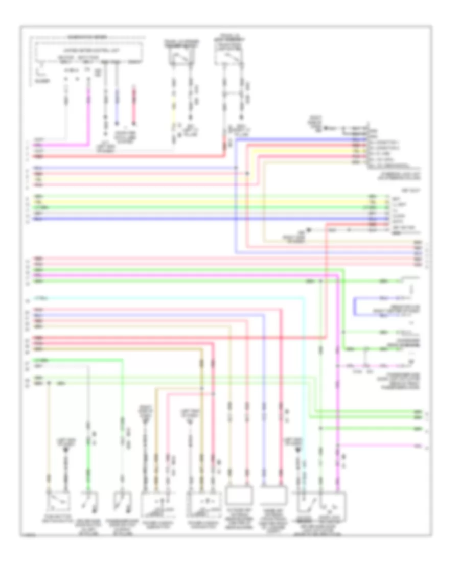 https://portal-diagnostov.com/license.html
Automotive Electricians Portal FZCO
Automotive Electricians Portal FZCO
https://portal-diagnostov.com/license.html
https://portal-diagnostov.com/license.html
Automotive Electricians Portal FZCO
Automotive Electricians Portal FZCOList of elements for Power Door Locks Wiring Diagram, with Intelligent Key Unit (2 of 3) for Nissan GT-R Premium 2014:
- (left end of dash) m11
- (right side of dash) m95
- B151
- B201
- B231 (right "c" pillar)
- B239
- B31 (left "c" pillar)
- B351
- B59
- Bat
- Batt pwr sply
- Buzzer
- Can-h
- Can-l
- Clock
- Combination meter
- Computer data lines system
- Condenser (rear of engine)
- D31
- Data
- Door lock actuator
- Driver side door lock actuator (rear of driver's door)
- Driver side door switch (in left "b" pillar)
- Gnd
- Ign pwr sply
- Ill
- Ill bat
- Inside key antenna (trunk room) (center front of luggage compt)
- Key ind
- Key slot
- Key sw sig
- Lock
- M11 (left end of dash)
- M117
- M124
- M95 (right side of dash)
- Outside key antenna (rear bumper) (center of rear bumper)
- Passenger side door lock actuator (rear of front passenger's door)
- Passenger side door switch (in right "b" pillar)
- Pnk
- Power window main-switch
- Power window sub-switch
- Push button ignition switch
- Red
- Resistor m126 (right center of dash)
- S/l (k line)
- S/l 12v (cpu)
- S/l 12v (mechanical)
- S/l condition 1
- S/l condition 2
- Steering lock unit (on steering column)
- Trunk lid lock assembly
- Trunk lid opener request switch
- Trunk room lamp switch
- Un lock
- Unified meter control unit
- Unlock sensor
Power Door Locks Wiring Diagram, with Intelligent Key Unit (3 of 3) for Nissan GT-R Premium 2014
 https://portal-diagnostov.com/license.html
Automotive Electricians Portal FZCO
Automotive Electricians Portal FZCO
https://portal-diagnostov.com/license.html
https://portal-diagnostov.com/license.html
Automotive Electricians Portal FZCO
Automotive Electricians Portal FZCOList of elements for Power Door Locks Wiring Diagram, with Intelligent Key Unit (3 of 3) for Nissan GT-R Premium 2014:
- (right rear of engine compt) e46
- B201
- Combination switch (spiral cable) (in steering column)
- Computer data lines system
- Cpu
- Diode
- E106
- E106 m6
- E20 (left rear of engine compt)
- E32
- E33
- E46 (right rear of engine compt)
- E79
- E80
- E81
- E82
- Fuel lid lock actuator (right side of luggage compt)
- Fuse 10a
- Fuse 15a
- Headlamp high relay
- Headlamp low relay
- Headlights system
- Hood switch (left front of engine compt)
- Horn (high)
- Horn (low)
- Horn relay 1 (on fuse/fusible link & relay box)
- Horn relay 2 (in left rear engine compt relay holder)
- Horn switch
- Hot at all times
- Ipdm e/r (intelligent power distribution module engine room) (right rear corner of engine compt)
- M117
- M303
- M36
- Nca
- Pnk
- Red
- Resistor
- Steering lock relay
- Vehicle security horn
Power Door Locks Wiring Diagram, without Intelligent Key Unit for Nissan GT-R Premium 2014
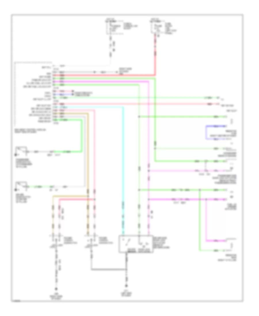 https://portal-diagnostov.com/license.html
Automotive Electricians Portal FZCO
Automotive Electricians Portal FZCO
https://portal-diagnostov.com/license.html
https://portal-diagnostov.com/license.html
Automotive Electricians Portal FZCO
Automotive Electricians Portal FZCOList of elements for Power Door Locks Wiring Diagram, without Intelligent Key Unit for Nissan GT-R Premium 2014:
- (right side of dash) m95
- All dr, fuel lid lk o/p
- B201
- B201 m117
- Bat (f/l)
- Bat (fuse)
- Bcm (body control module) (right end of dash)
- Can-h
- Can-l
- Computer data lines system
- Condenser (rear of engine)
- D31
- D31 m124
- Door lock actuator
- Dr lk/unlk sw lk
- Dr lk/unlk sw unlk
- Driver door switch (in driver "b" pillar)
- Driver side door lock actuator (rear of driver's door)
- Drv dr sw
- Drv dr unlk sens
- Drv dr, fuel lid unlk o/p
- E106 m6
- Fuel lid opener actuator
- Fuse & fusible link block
- Fuse 10a
- Fuse block (j/b) (left kick panel)
- Fusible link i 40a
- Gnd
- Hot at all times
- Ill
- Key slot
- Key slot ill o/p
- Key slot sw
- Key sw sig
- Lock
- M11 (left end of dash)
- M117
- M118
- M119
- M122
- M123
- M124
- M124 m31
- M95 (right side of dash)
- Pass dr sw
- Pass dr unlk o/p
- Passenger door switch (in passenger "b" pillar)
- Passenger side door lock actuator (rear of front passenger's door)
- Pnk
- Power window main-switch
- Power window sub-switch
- Red
- Resistor b245 (right "c" pillar)
- Resistor m126 (right center of dash)
- Un lock
- Unlock sensor
POWER MIRRORS
Auto Anti-dazzling Inside Mirror Wiring Diagram for Nissan GT-R Premium 2014
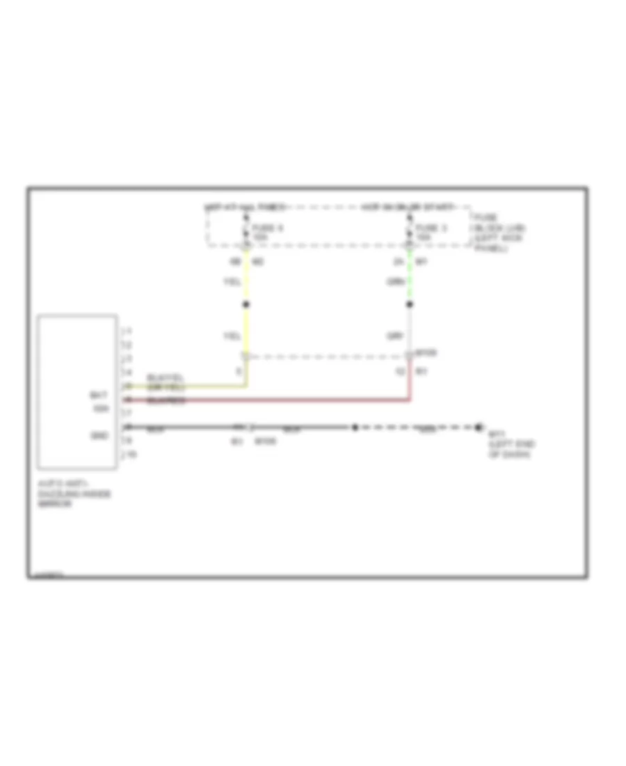 https://portal-diagnostov.com/license.html
Automotive Electricians Portal FZCO
Automotive Electricians Portal FZCO
https://portal-diagnostov.com/license.html
https://portal-diagnostov.com/license.html
Automotive Electricians Portal FZCO
Automotive Electricians Portal FZCOList of elements for Auto Anti-dazzling Inside Mirror Wiring Diagram for Nissan GT-R Premium 2014:
- Auto anti- dazzling inside mirror
- Bat
- Fuse 3 10a
- Fuse 6 10a
- Fuse block (j/b) (left kick panel)
- Gnd
- Hot at all times
- Hot in on or start
- Ign
- M106
- M11 (left end of dash)
Power Mirrors Wiring Diagram for Nissan GT-R Premium 2014
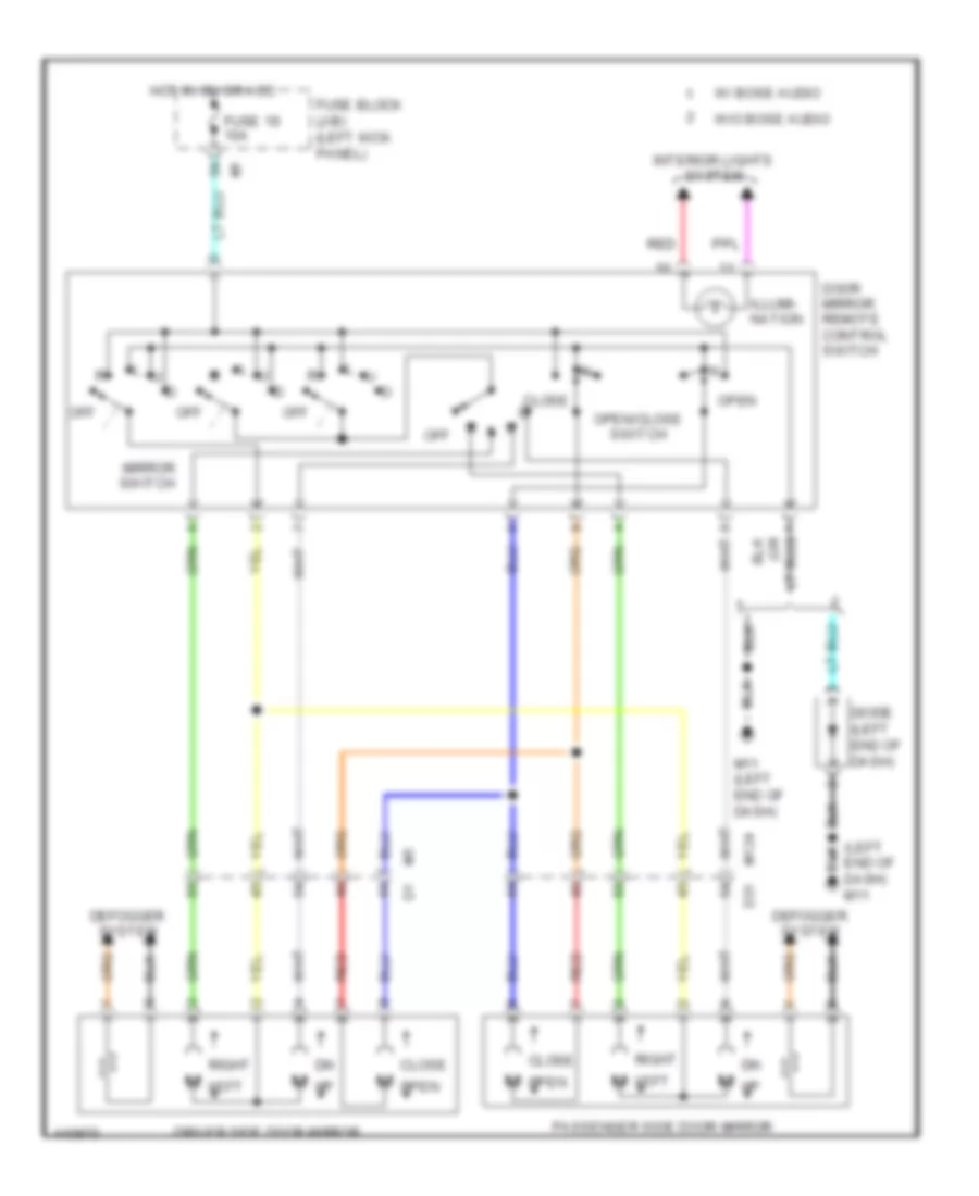 https://portal-diagnostov.com/license.html
Automotive Electricians Portal FZCO
Automotive Electricians Portal FZCO
https://portal-diagnostov.com/license.html
https://portal-diagnostov.com/license.html
Automotive Electricians Portal FZCO
Automotive Electricians Portal FZCOList of elements for Power Mirrors Wiring Diagram for Nissan GT-R Premium 2014:
- (left end of dash) m11
- Close
- D31
- Defogger system
- Diode (left end of dash)
- Door mirror remote control switch
- Driver side door mirror
- Fuse 19 10a
- Fuse block (j/b) (left kick panel)
- Hot in on or acc
- Illumi- nation
- Interior lights system
- Left
- M left
- M open
- M11 (left end of dash)
- M124
- Mirror switch
- Off
- Open
- Open/close switch
- Passenger side door mirror
- Red
- Right
- W/ bose audio
- W/o bose audio
POWER SEATS
Driver Power Seat Wiring Diagram for Nissan GT-R Premium 2014
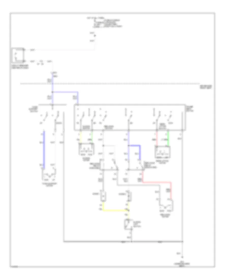 https://portal-diagnostov.com/license.html
Automotive Electricians Portal FZCO
Automotive Electricians Portal FZCO
https://portal-diagnostov.com/license.html
https://portal-diagnostov.com/license.html
Automotive Electricians Portal FZCO
Automotive Electricians Portal FZCOList of elements for Driver Power Seat Wiring Diagram for Nissan GT-R Premium 2014:
- B10
- B14 (under driver's seat)
- B501
- Bwd
- Circuit breaker (center of dash)
- Diode 1
- Diode 2
- Down
- Driver side front seat
- Dwn
- Fuse & fusible link block (on battery positive (+) post)
- Fusible link i 40a
- Fwd
- Hot at all times
- Power seat switch
- Rear lifting motor
- Rear lifting switch
- Reclining motor
- Reclining relay (backward)
- Reclining relay (forward)
- Reclining switch
- Red
- Sliding limit switch
- Sliding motor
- Sliding switch
- Thigh support motor
- Thigh support switch
Heated Seats Wiring Diagram for Nissan GT-R Premium 2014
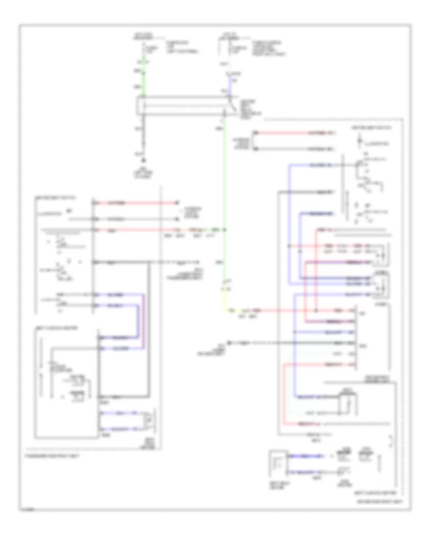 https://portal-diagnostov.com/license.html
Automotive Electricians Portal FZCO
Automotive Electricians Portal FZCO
https://portal-diagnostov.com/license.html
https://portal-diagnostov.com/license.html
Automotive Electricians Portal FZCO
Automotive Electricians Portal FZCOList of elements for Heated Seats Wiring Diagram for Nissan GT-R Premium 2014:
- (left kick panel)
- 2a m1
- B10 b501
- B14 (under driver's seat)
- B201 m117
- B210 b551
- B214 (under front passenger's seat)
- B508
- B518
- B555
- B556
- Diode 3
- Diode 4
- Driver side front seat
- E106
- Fuse & fusible link block (on battery positive (+) post)
- Fuse 3 10a
- Fuse 35 15a
- Fuse block (j/b)
- Gnd
- Heat sensor
- Heated seat control unit
- Heated seat relay (center of dash)
- Heated seat switch
- Heater
- Hot at all times
- Hot in on or start
- Ign
- Illumination
- Interior lights system
- M55 (left side of dash)
- Main heater
- Off
- Passenger side front seat
- Red
- Seat back heater
- Seat cushion heater
- Sub- heater
Passenger Power Seat Wiring Diagram for Nissan GT-R Premium 2014
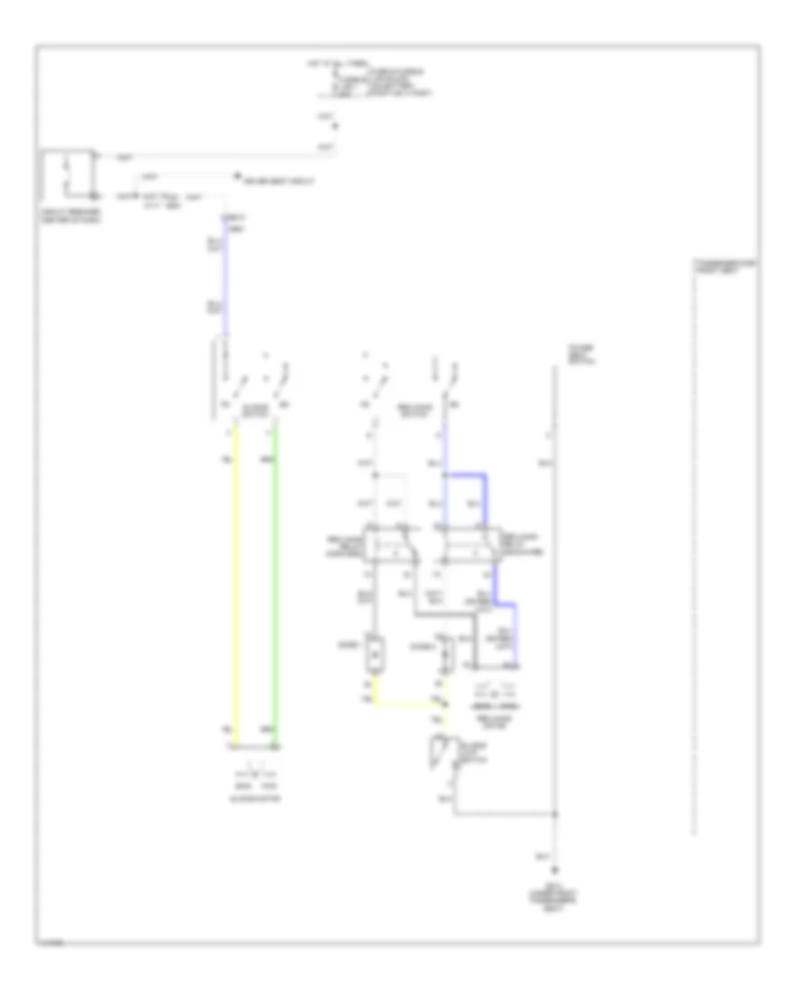 https://portal-diagnostov.com/license.html
Automotive Electricians Portal FZCO
Automotive Electricians Portal FZCO
https://portal-diagnostov.com/license.html
https://portal-diagnostov.com/license.html
Automotive Electricians Portal FZCO
Automotive Electricians Portal FZCOList of elements for Passenger Power Seat Wiring Diagram for Nissan GT-R Premium 2014:
- B201 m117
- B210
- B214 (under front passenger's seat)
- B551
- Bwd
- Circuit breaker (center of dash)
- Diode 1
- Diode 2
- Driver seat circuit
- Fuse & fusible link block (on battery positive (+) post)
- Fusible link i 40a
- Fwd
- Hot at all times
- Passenger side front seat
- Power seat switch
- Reclining motor
- Reclining relay (backward)
- Reclining relay (forward)
- Reclining switch
- Sliding limit switch
- Sliding motor
- Sliding switch
POWER WINDOWS
Power Windows Wiring Diagram for Nissan GT-R Premium 2014
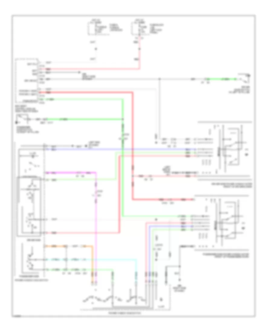 https://portal-diagnostov.com/license.html
Automotive Electricians Portal FZCO
Automotive Electricians Portal FZCO
https://portal-diagnostov.com/license.html
https://portal-diagnostov.com/license.html
Automotive Electricians Portal FZCO
Automotive Electricians Portal FZCOList of elements for Power Windows Wiring Diagram for Nissan GT-R Premium 2014:
- (left end of dash) m11
- B201 m117
- Bat
- Bat (f/l)
- Bcm (body control module) (right end of dash)
- D1 m5
- D31
- Driver door switch (in left "b" pillar)
- Driver side
- Driver side power window motor (front of driver's door)
- Drv dr sw
- Fuse & fusible link block
- Fuse 10a
- Fuse block (j/b) (left kick panel)
- Fusible link i 40a
- Gnd
- Hot at all times
- Illum
- Lock switch
- M118
- M119
- M123
- M124
- M95 (right side of dash)
- Module
- Pass dr sw
- Passenger door switch (in right "b" pillar)
- Passenger side
- Passenger side power window motor (front of passenger's door)
- Power window main switch
- Power window sub switch
- Pwr sply (bat)
- Pwr sply (rap)
- Red
RADIO
Radio Wiring Diagram, Base (1 of 3) for Nissan GT-R Premium 2014
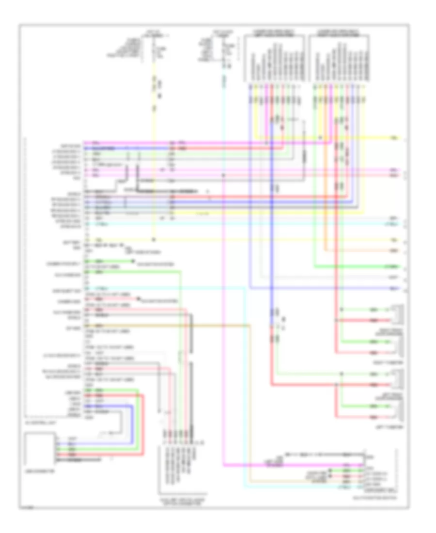 https://portal-diagnostov.com/license.html
Automotive Electricians Portal FZCO
Automotive Electricians Portal FZCO
https://portal-diagnostov.com/license.html
https://portal-diagnostov.com/license.html
Automotive Electricians Portal FZCO
Automotive Electricians Portal FZCOList of elements for Radio Wiring Diagram, Base (1 of 3) for Nissan GT-R Premium 2014:
- (23 to 25 not used)
- (or red)
- (pins: 102 to 103 n0t used)
- (pins: 105 to 116 n0t used)
- (pins: 120 to 128 n0t used)
- (pins: 30 to 41 n0t used)
- (pins: 43 to 45 n0t used)
- (pins: 50 to 60 n0t used)
- (under driver's seat) left audio amplifier
- (under driver's seat) right audio amplifier
- Acc
- Amp on sig
- Audio amp on sig
- Aux image gnd
- Aux image sig
- Aux sound sig gnd
- Auxiliary inputs jacks (option connector)
- Av comm (h)
- Av comm (l)
- Av control unit
- B1 m7
- Battery
- Camera gnd
- Camera pwr sply
- Computer data lines system
- Disk eject sig
- E106
- Fuse & fusible link block (on battery positive (+) post)
- Fuse 10a
- Fuse 15a
- Fuse block (j/b) (left kick panel)
- Gnd
- Hot at all times
- Hot in acc or on
- Left front door speaker
- Left tweeter
- Lf door speaker (+)
- Lf door speaker (-)
- Lf sound sig (+)
- Lf sound sig (-)
- Lh aux sound sig (+)
- Lr sound sig (+)
- Lr sound sig (-)
- Lr speaker (+)
- Lr speaker (-)
- M124 d31
- M201
- M202
- M204
- M205
- M5 d1
- M55 (left side of dash)
- Multi-function switch
- Navigation system
- Pnk
- Red
- Rf door speaker (+)
- Rf door speaker (-)
- Rf sound sig (+)
- Rf sound sig (-)
- Rh aux sound sig (+)
- Right front door speaker
- Right tweeter
- Rr sound sig (+)
- Rr sound sig (-)
- Rr speaker (+)
- Rr speaker (-)
- Shield
- Strg sw a
- Strg sw b
- Strg sw gnd
- Sw gnd
- Usb connector
- Usb d+
- Usb d-
- Usb gnd
- V bus
Radio Wiring Diagram, Base (2 of 3) for Nissan GT-R Premium 2014
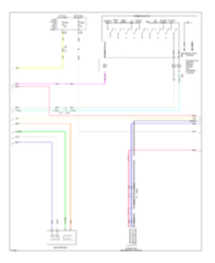 https://portal-diagnostov.com/license.html
Automotive Electricians Portal FZCO
Automotive Electricians Portal FZCO
https://portal-diagnostov.com/license.html
https://portal-diagnostov.com/license.html
Automotive Electricians Portal FZCO
Automotive Electricians Portal FZCOList of elements for Radio Wiring Diagram, Base (2 of 3) for Nissan GT-R Premium 2014:
- 10b
- 12c
- Combination switch (spiral cable) (in steering column)
- Fuse 10a
- Fuse 20a
- Fuse block (j/b) (left kick panel)
- Hot at all times
- Hot in on or start
- Interior lights system
- M106
- M140
- M141
- M303
- M36
- M7 b1
- Microphone (center front of roof)
- Microphone gnd
- Microphone sig
- Microphone vcc
- Mrk
- Nca
- Pnk
- Rear speaker
- Seek down
- Seek up
- Shield
- Source sw
- Start/ stop
- Steering switch
- Tel sw
- Volume down
- Volume up
- Vr sw
Radio Wiring Diagram, Base (3 of 3) for Nissan GT-R Premium 2014
 https://portal-diagnostov.com/license.html
Automotive Electricians Portal FZCO
Automotive Electricians Portal FZCO
https://portal-diagnostov.com/license.html
https://portal-diagnostov.com/license.html
Automotive Electricians Portal FZCO
Automotive Electricians Portal FZCOList of elements for Radio Wiring Diagram, Base (3 of 3) for Nissan GT-R Premium 2014:
- (pins: 61 to 64 n0t used)
- Acc
- Am fm main
- Antenna amp on sig
- Antenna amplifier
- Av comm(h)
- Av comm(l)
- Av control unit
- Batt
- Bcm (body control module) (right end of dash)
- Camera img sig
- Can-h
- Can-l
- Combination meter
- Comm
- Comp syn sig
- Compostion image gnd
- Compostion image sig
- Computer data lines system
- Display unit
- Exterior lights system
- Fm sub
- Gnd
- Gps antenna
- Gps antenna sig
- Ignition
- Ill
- Image gnd
- Image sig
- Image sig(+)
- Image sig(-) rgb digtal
- Interior lights system
- M203
- M371
- M372
- M373
- M375
- M376
- M379
- M381
- M390
- M391
- M392
- M396
- M397
- M55 (left side of dash)
- M93
- Microphone gnd
- Microphone sig
- Microphone vcc
- Navigation
- Nca
- Parking brake
- Parking brake switch
- Pnk
- Prk brk sw
- Red
- Reverse
- Rgb digital image sig(+)
- Rgb digital image sig(-)
- Satellite antenna sig
- Satellite radio antenna
- Shield
- Syn sig
- System
- Vcc (8 pluse)
- Vehicle speed (8-pluse)
- Window antenna (main)
- Window antenna (sub)
Radio Wiring Diagram, Bose (1 of 3) for Nissan GT-R Premium 2014
 https://portal-diagnostov.com/license.html
Automotive Electricians Portal FZCO
Automotive Electricians Portal FZCO
https://portal-diagnostov.com/license.html
https://portal-diagnostov.com/license.html
Automotive Electricians Portal FZCO
Automotive Electricians Portal FZCOList of elements for Radio Wiring Diagram, Bose (1 of 3) for Nissan GT-R Premium 2014:
- 10b
- 12c
- Acc
- Aux image gnd
- Aux image sig
- Av control unit
- B14 (under driver's seat)
- Battery
- Bose amp. on sig
- Camera gnd
- Camera pwr sply
- Disk eject sig
- E106
- Fuse & fusible link block (on battery positive (+) post)
- Fuse 10a
- Fuse 15a
- Fuse 20a
- Fuse block (j/b) (left kick panel)
- Gnd
- Hot at all times
- Hot in acc or on
- Hot in on or start
- Lf audio sig (+)
- Lf audio sig (-)
- Lr audio sig (+)
- Lr audio sig (-)
- M201
- M202
- M205
- M55 (left side of dash)
- M7 b1
- Navigation system
- Pnk
- Red
- Rf audio sig (+)
- Rf audio sig (-)
- Rr audio sig (+)
- Rr audio sig (-)
- Shield
- Sound sig woofer (+)
- Sound sig woofer (-)
- Strg sw a
- Strg sw b
- Strg sw gnd
- Sw gnd
- Usb connector
- Usb d+
- Usb d-
- Usb gnd
- V bus
- Woofer
- Woofer amp on sig
Radio Wiring Diagram, Bose (2 of 3) for Nissan GT-R Premium 2014
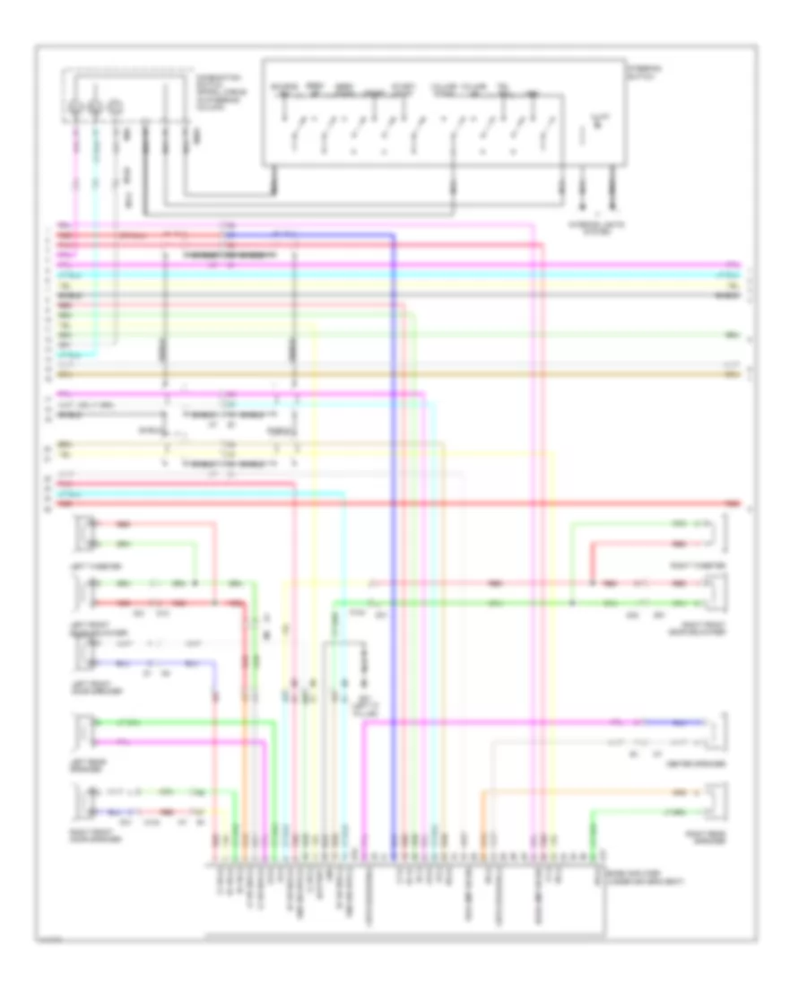 https://portal-diagnostov.com/license.html
Automotive Electricians Portal FZCO
Automotive Electricians Portal FZCO
https://portal-diagnostov.com/license.html
https://portal-diagnostov.com/license.html
Automotive Electricians Portal FZCO
Automotive Electricians Portal FZCOList of elements for Radio Wiring Diagram, Bose (2 of 3) for Nissan GT-R Premium 2014:
- B16
- B17
- B31 (left "c" pillar)
- Battery
- Bose amp on sig
- Bose amplifier (under driver's seat)
- Center speaker
- Cntr speaker (-)
- Cntr speaker(+)
- Combination switch (spiral cable) (in steering column)
- D12
- D21
- D31
- D42
- D51
- Gnd
- Illum
- Interior lights system
- Left front door speaker
- Left front door squawker
- Left rear speaker
- Left tweeter
- Lf (+)
- Lf (-)
- Lf dr (+)
- Lf dr (-)
- Lf dr squ (+)
- Lf dr squ (-)
- Lr (+)
- Lr (-)
- M124
- M140
- M141
- M303
- M36
- Mrk
- Nca
- Pnk
- Red
- Rf (+)
- Rf (-)
- Rf dr (+)
- Rf dr (-)
- Rf dr squ (+)
- Rf dr squ (-)
- Right front door speaker
- Right front door squawker
- Right rear speaker
- Right tweeter
- Rr (+)
- Rr (-)
- Seek down
- Seek up
- Shield
- Snd sig wfr (+)
- Snd sig wfr (-)
- Source sw
- Start/ stop
- Steering switch
- Tel sw
- Volume down
- Volume up
- Vr sw
- Wfr amp on sig
Radio Wiring Diagram, Bose (3 of 3) for Nissan GT-R Premium 2014
 https://portal-diagnostov.com/license.html
Automotive Electricians Portal FZCO
Automotive Electricians Portal FZCO
https://portal-diagnostov.com/license.html
https://portal-diagnostov.com/license.html
Automotive Electricians Portal FZCO
Automotive Electricians Portal FZCOList of elements for Radio Wiring Diagram, Bose (3 of 3) for Nissan GT-R Premium 2014:
- Acc
- Am-fm main
- Antenna amp
- Antenna amp. on sig
- Aux image gnd
- Aux image sig
- Aux snd sig gnd
- Auxiliary input jacks (option connector)
- Av comm (h)
- Av comm (l)
- Av control unit
- Battery
- Camera img sig
- Can-h
- Can-l
- Combination meter
- Comm (cont-disp)
- Comm (disp-cont)
- Comp image gnd
- Comp image sig
- Comp sync sig
- Composite image gnd
- Composite image sig
- Computer data lines system
- Disk eject sig
- Display unit
- Exterior lights system
- Fm sub
- Gnd
- Gps antenna
- Gps antenna sig
- Ign
- Illumination
- Image sig(+) rgb digital
- Interior lights system
- Lh aux snd sig (+)
- Lt aux snd sig (+)
- M106
- M203
- M204
- M371
- M372
- M373
- M375
- M376
- M379
- M381
- M390
- M391
- M392
- M396
- M397 image sig(-) rgb digital
- M55 (left side of dash)
- M93
- Microphone (center front of roof)
- Microphone gnd
- Microphone sig
- Microphone vcc
- Multi-function switch
- Nca
- Parking brake
- Parking brake switch
- Pnk
- Prk brk sw
- Red
- Reverse
- Rgb digital image sig(+)
- Rgb digital image sig(-)
- Rh aux snd sig (+)
- Rt aux snd sig (+)
- Satellite antenna sig
- Satellite radio antenna
- Shield
- Speed sig (8-pulse)
- Sw gnd
- System navigation
- Window antenna (main)
- Window antenna (sub)
SHIFT INTERLOCK
Shift Interlock Wiring Diagram for Nissan GT-R Premium 2014
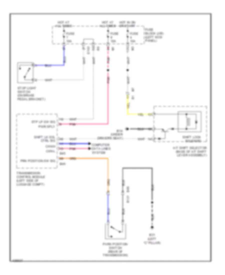 https://portal-diagnostov.com/license.html
Automotive Electricians Portal FZCO
Automotive Electricians Portal FZCO
https://portal-diagnostov.com/license.html
https://portal-diagnostov.com/license.html
Automotive Electricians Portal FZCO
Automotive Electricians Portal FZCOList of elements for Shift Interlock Wiring Diagram for Nissan GT-R Premium 2014:
- "c" pillar)
- (left
- 12c
- A/t shift selector (base of a/t shift lever assembly)
- B14 (under driver's seat)
- B31
- B45
- B46
- B48 b121
- Can-h
- Can-l
- Computer data lines
- E103
- Fuse 10a
- Fuse block (j/b) (left kick panel)
- Hot at all times
- Hot in on or start
- M7 b1
- Park position switch (rear of transmission)
- Pnk
- Prk position sw sig
- Pwr sply
- Shift lk sol ctrl sig
- Shift lock solenoid
- Stop light switch (on brake pedal bracket)
- Stp lp sw sig
- System
- Transmission control module (left side of luggage compt)
STARTING/CHARGING
Charging Wiring Diagram for Nissan GT-R Premium 2014
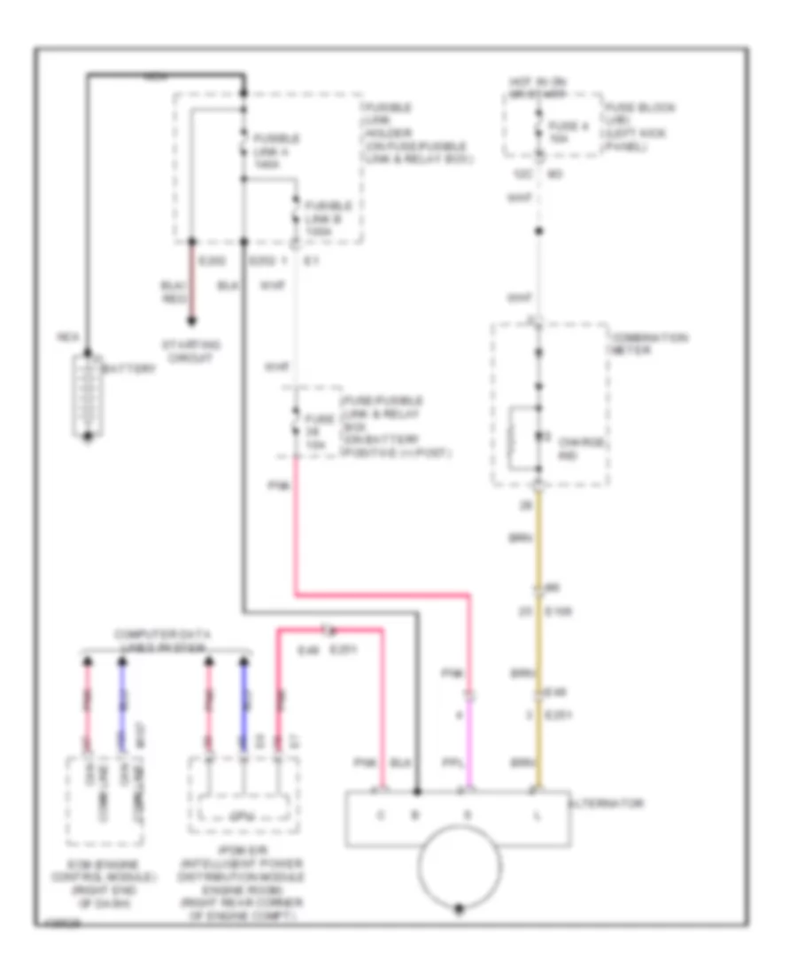 https://portal-diagnostov.com/license.html
Automotive Electricians Portal FZCO
Automotive Electricians Portal FZCO
https://portal-diagnostov.com/license.html
https://portal-diagnostov.com/license.html
Automotive Electricians Portal FZCO
Automotive Electricians Portal FZCOList of elements for Charging Wiring Diagram for Nissan GT-R Premium 2014:
- 12c
- Alternator
- Battery
- Charge ind
- Combination meter
- Comm line can
- Computer data lines system
- Cpu
- E106
- E202
- E251
- E251 e49
- E252
- E49
- Ecm (engine control module) (right end of dash)
- Fuse 10a
- Fuse 4 10a
- Fuse block (j/b) (left kick panel)
- Fuse/fusible link & relay box (on battery positive (+) post)
- Fusible link a 140a
- Fusible link b 100a
- Fusible link holder (on fuse/fusible link & relay box)
- Hot in on or start
- Ipdm e/r (intelligent power distribution module engine room) (right rear corner of engine compt)
- M107
- Nca
- Pnk
- Starting circuit
Starting Wiring Diagram for Nissan GT-R Premium 2014
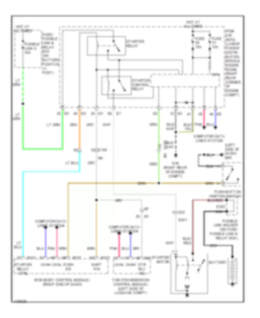 https://portal-diagnostov.com/license.html
Automotive Electricians Portal FZCO
Automotive Electricians Portal FZCO
https://portal-diagnostov.com/license.html
https://portal-diagnostov.com/license.html
Automotive Electricians Portal FZCO
Automotive Electricians Portal FZCOList of elements for Starting Wiring Diagram for Nissan GT-R Premium 2014:
- (left side of dash) m55
- B45
- Battery
- Bcm (body control module) (right end of dash)
- Canh
- Canl
- Computer data lines system
- Cpu
- E106
- E201
- E202
- E23
- E46 (right rear of engine compt)
- Fuse 15a
- Fuse/ fusible link & relay box (on battery positive (+) post)
- Fusible link g 30a
- Fusible link holder (on fuse/ fusible link & relay box)
- Hot at all times
- Ipdm e/r (inte- lligent power distri- bution module engine room) (right rear corner of engine compt)
- M121
- M122
- M123
- Nca
- Pnk
- Push sw
- Push-button ignition switch
- Shift p/n
- Starter control relay
- Starter motor
- Starter relay
- Starter relay ctrl
- Str rly sig
- Tcm (transmission control module) (left side of luggage compt)
SUPPLEMENTAL RESTRAINTS
Supplemental Restraints Wiring Diagram (1 of 2) for Nissan GT-R Premium 2014
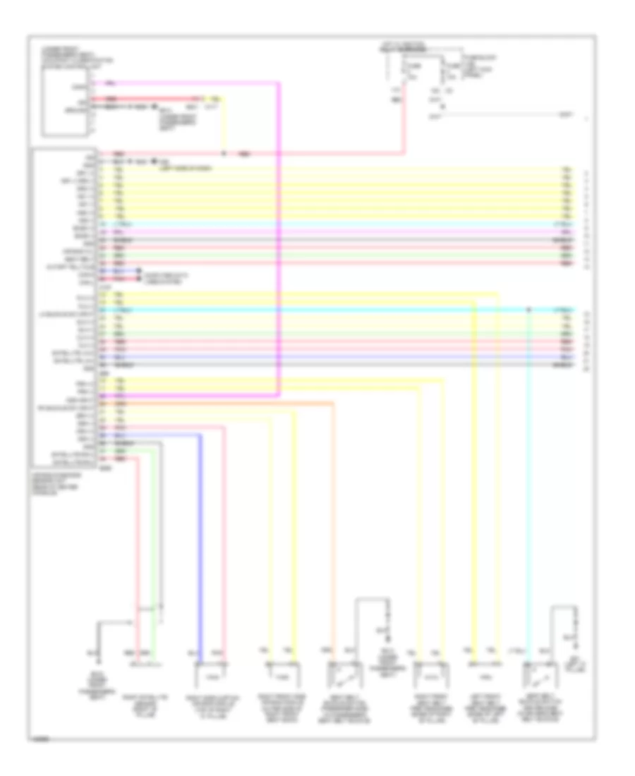 https://portal-diagnostov.com/license.html
Automotive Electricians Portal FZCO
Automotive Electricians Portal FZCO
https://portal-diagnostov.com/license.html
https://portal-diagnostov.com/license.html
Automotive Electricians Portal FZCO
Automotive Electricians Portal FZCOList of elements for Supplemental Restraints Wiring Diagram (1 of 2) for Nissan GT-R Premium 2014:
- "c" pillar)
- (under front passenger's seat) occupant classification system control unit
- 11c
- 12c
- Air bag diagnosis sensor unit (rear of center console)
- Air bag w/l
- As1 (+)
- As1 (-)
- As2 (+)
- As2 (-)
- B201
- B214 (under front passenger's seat)
- B215 (under front passenger's seat)
- B268
- B31 (left "c" pillar)
- B69
- Can-h
- Can-l
- Clh (+)
- Clh (-)
- Comm
- Computer data lines system
- Crh (+)
- Crh (-)
- Cutoff telltale
- Dr1 (+)
- Dr1 (-) dr2 (-)
- Dr2 (+)
- Eczs (+)
- Eczs (-)
- Fuse 10a
- Fuse block (j/b) (left kick panel)
- Gnd
- Ground
- Hot w/ ignition relay energized
- Ign
- Left front seat belt pre-tensioner (base of left "b" pillar)
- Lh buckle sw input
- M117
- M157
- M55 (left side of dash)
- Ods input
- Plh (+)
- Plh (-)
- Pnk
- Prh (+)
- Prh (-)
- Red
- Rh buckle sw input
- Right front seat belt pre-tensioner (base of right "b" pillar)
- Right front side air bag module (outer side of right front seat back)
- Right satellite sensor (right "b" pillar)
- Right side curtain air bag module (top of right
- Satellite lh(+)
- Satellite lh(-)
- Satellite rh(+)
- Satellite rh(-)
- Seat belt
- Seat belt buckle switch (driver side) (in driver's seat belt buckle)
- Seat belt buckle switch (passenger side) (in passenger's seat belt buckle)
- Shield
- Slh (+)
- Slh (-)
- Srh (+)
- Srh (-)
Supplemental Restraints Wiring Diagram (2 of 2) for Nissan GT-R Premium 2014
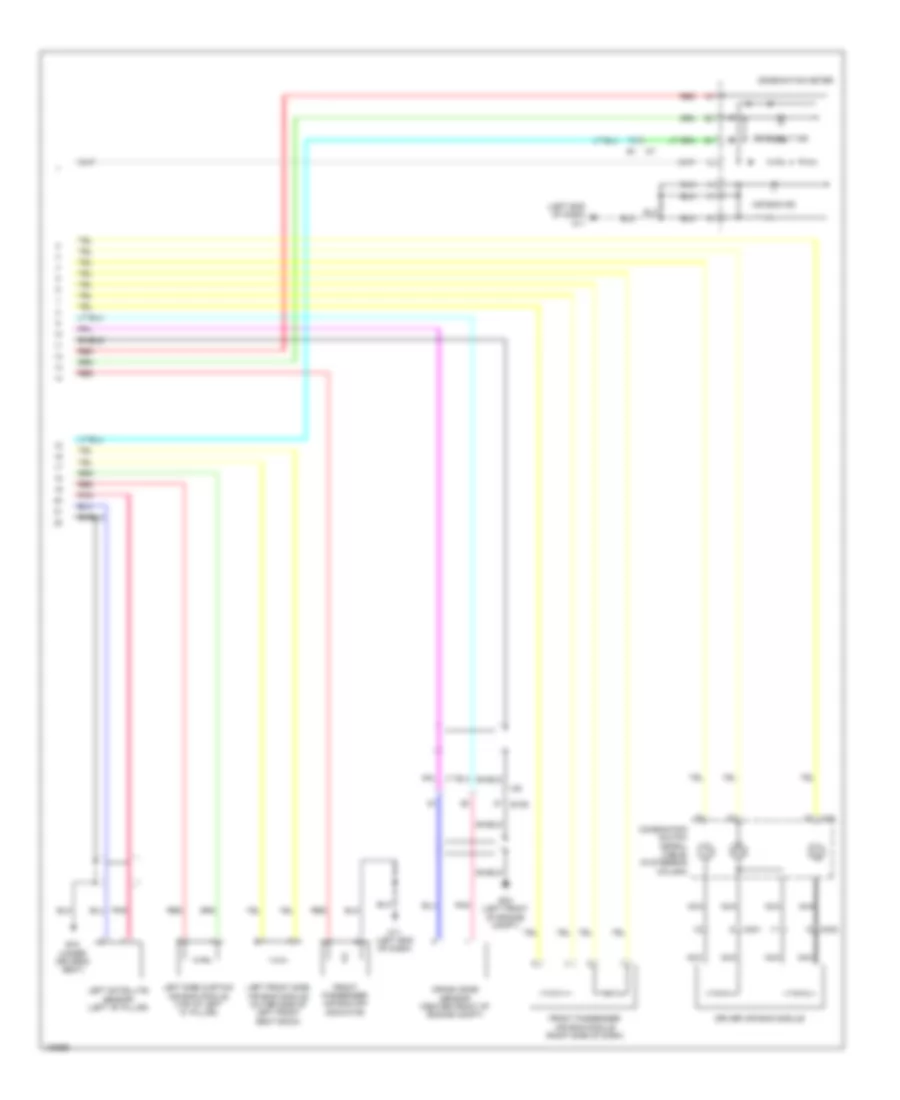 https://portal-diagnostov.com/license.html
Automotive Electricians Portal FZCO
Automotive Electricians Portal FZCO
https://portal-diagnostov.com/license.html
https://portal-diagnostov.com/license.html
Automotive Electricians Portal FZCO
Automotive Electricians Portal FZCOList of elements for Supplemental Restraints Wiring Diagram (2 of 2) for Nissan GT-R Premium 2014:
- (left end of dash) m11
- Air bag ind
- B15 (under driver's seat)
- Combination meter
- Combination switch (spiral cable) (in steering column)
- Crash zone sensor (center front of engine compt)
- Driver air bag module
- E106
- E34 (left front of engine compt)
- Front passenger air bag module (right side of dash)
- Front passenger air bag off indicator
- Left front side air bag module (outer side of left front seat back)
- Left satellite sensor (left "b" pillar)
- Left side curtain air bag module (top of left "c" pillar)
- M11 (left end of dash)
- M301
- M302
- M35
- Nca
- Pnk
- Red
- Seat belt ind
- Shield
TRANSMISSION
4WD Wiring Diagram for Nissan GT-R Premium 2014
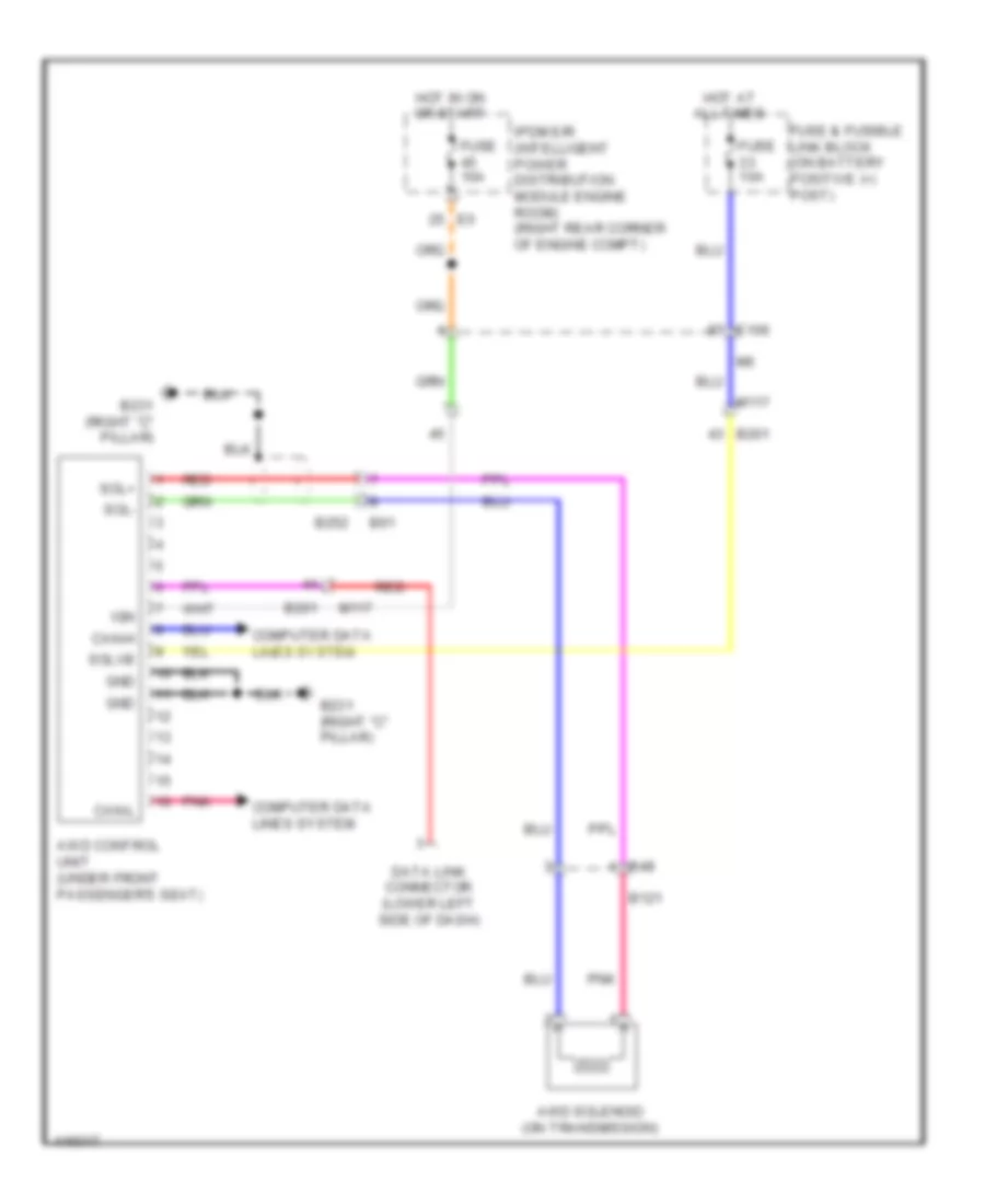 https://portal-diagnostov.com/license.html
Automotive Electricians Portal FZCO
Automotive Electricians Portal FZCO
https://portal-diagnostov.com/license.html
https://portal-diagnostov.com/license.html
Automotive Electricians Portal FZCO
Automotive Electricians Portal FZCOList of elements for 4WD Wiring Diagram for Nissan GT-R Premium 2014:
- Awd control unit (under front passenger's seat)
- Awd solenoid (on transmission)
- B121
- B201
- B231 (right "c" pillar)
- B252
- B48
- B61
- Can-h
- Can-l
- Computer data lines system
- Data link connector (lower left side of dash)
- E106
- Fuse & fusible link block (on battery positive (+) post)
- Fuse 10a
- Gnd
- Hot at all times
- Hot in on or start
- Ign
- Ipdm e/r (intelligent power distribution module engine room) (right rear corner of engine compt)
- M117
- Pnk
- Red
- Sol+
- Sol-
- Solvb
A/T Wiring Diagram (1 of 3) for Nissan GT-R Premium 2014
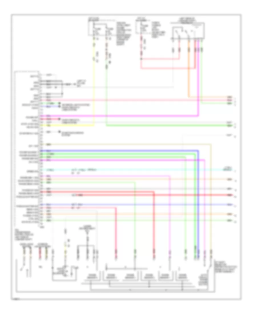 https://portal-diagnostov.com/license.html
Automotive Electricians Portal FZCO
Automotive Electricians Portal FZCO
https://portal-diagnostov.com/license.html
https://portal-diagnostov.com/license.html
Automotive Electricians Portal FZCO
Automotive Electricians Portal FZCOList of elements for A/T Wiring Diagram (1 of 3) for Nissan GT-R Premium 2014:
- (left "c" pillar) b31
- (left rear of luggage compt) tcm relay
- (under driver's seat) b14
- A/t shift selector (detention switch) (base of a/t shift lever assembly)
- Auto/ manual range change switch
- B45
- Backup lp sig
- Batt-1
- Batt-2
- Batt-3
- Can-h
- Can-l
- Computer data lines system
- Ctrl sig
- Door locks system
- E104
- E106
- Exterior lights system
- Fuse & fusible link block (on battery positive (+) post)
- Fuse 10a
- Fuse 20a
- Gnd
- Hot at all times
- Hot in on or start
- Ign sw sig
- Interior lights system
- Ipdm e/r (intelligent power distribution module engine room) (right rear corner of engine compt)
- Paddle shifter sig
- Pnk
- Power off
- Power source 1
- Power source 2
- R mode lp sig
- R mode sw sig
- Range sen 1 sig
- Range sen sig
- Range sens 2 sig
- Range sens 3 sig
- Range sensor
- Range sensor 1
- Range sensor 2
- Range sensor 3
- Range sensor 4
- Range sensor 5
- Red
- Save md lp sig
- Save mode sw sig
- Sens 4 sig
- Sens 5 sig
- Shift lock solenoid
- Speed sig
- Starter rly sig
- Starting/charging system
- Stop lp sw sig
- Sw 1 sig
- Sw 2 sig
- Tcm (transmission control module) (left side of luggage compt)
A/T Wiring Diagram (2 of 3) for Nissan GT-R Premium 2014
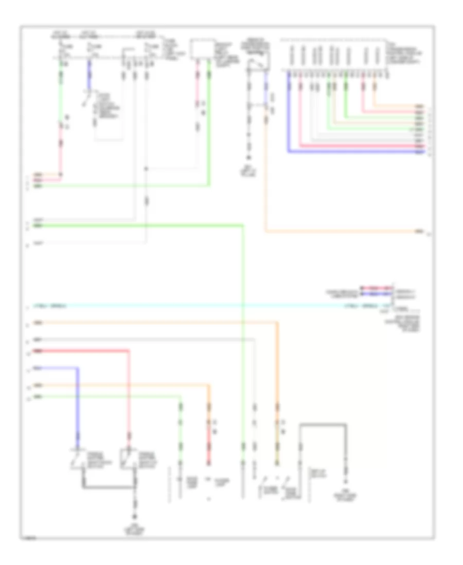 https://portal-diagnostov.com/license.html
Automotive Electricians Portal FZCO
Automotive Electricians Portal FZCO
https://portal-diagnostov.com/license.html
https://portal-diagnostov.com/license.html
Automotive Electricians Portal FZCO
Automotive Electricians Portal FZCOList of elements for A/T Wiring Diagram (2 of 3) for Nissan GT-R Premium 2014:
- (rear of transmission) park position switch
- (transmission control module) (left side of luggage compt)
- 12c
- B121
- B31 (left "c" pillar)
- B46
- B48
- Backup light relay (left rear of luggage compt)
- Computer data lines system
- E103
- Ecm (engine control module) (right end of dash)
- Fuse 10a
- Fuse block (j/b) (left kick panel)
- Hot at all times
- Hot in on or start
- M107
- M55 (left side of dash)
- M95 (right side of dash)
- Paddle shifter (shift-down switch)
- Paddle shifter (shift-up switch)
- Pnk
- R mode lamp
- R mode switch
- Red
- Save mode lamp
- Save mode switch
- Set-up switch
- Stop light switch (on brake pedal bracket)
- Tacho
- Tcm
- Valve (+)
- Valve (-)
- Valve 1(+)
- Valve 2(+)
- Valve 3(+)
- Valve 4(+)
- Vehcan-h1
- Vehcan-l1
A/T Wiring Diagram (3 of 3) for Nissan GT-R Premium 2014
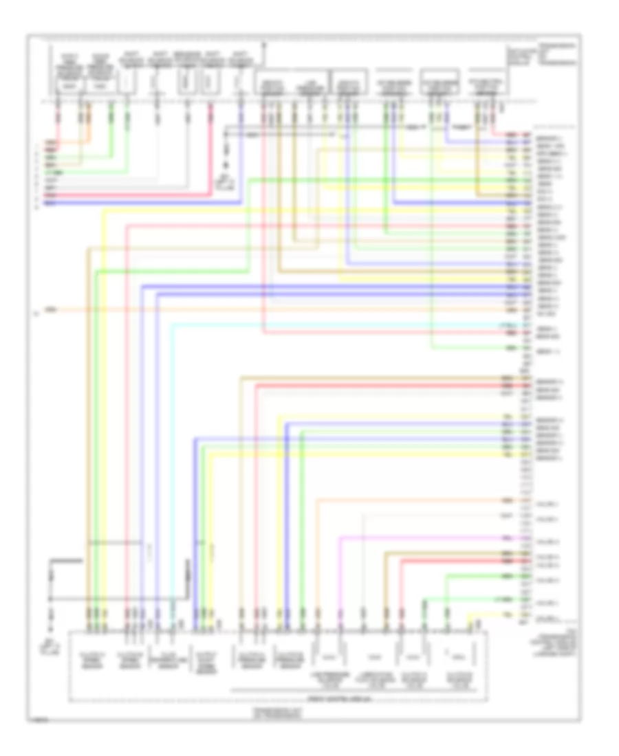 https://portal-diagnostov.com/license.html
Automotive Electricians Portal FZCO
Automotive Electricians Portal FZCO
https://portal-diagnostov.com/license.html
https://portal-diagnostov.com/license.html
Automotive Electricians Portal FZCO
Automotive Electricians Portal FZCOList of elements for A/T Wiring Diagram (3 of 3) for Nissan GT-R Premium 2014:
- 1st-reverse position sensor 1
- 1st-reverse position sensor 2
- 2nd-4th position sensor
- 3rd-5th position sensor
- 6th-neutral position sensor
- Actuator control module
- Axis a feed pressure solenoid valve
- Axis b feed pressure solenoid valve
- B31 (left "c" pillar)
- B46
- B47
- B49
- B50
- Clutch a pressure sensor
- Clutch a solenoid valve
- Clutch a speed sensor
- Clutch b pressure sensor
- Clutch b solenoid valve
- Clutch b speed sensor
- Fluid temperature sensor
- Front control module
- Line pressure sensor
- Line pressure solenoid valve
- Lubricating flow solenoid valve
- Nca
- Output shaft speed sensor
- Pnk
- Red
- Sens
- Sens (+)
- Sens (-)
- Sens 1 (+)
- Sens 1 (-)
- Sens 1 sig
- Sens 2 (+)
- Sens 2 (-)
- Sens 2 sig
- Sens sig
- Sensor (+)
- Sensor (-)
- Sequence solenoid valve
- Shift solenoid valve 1
- Shift solenoid valve 2
- Shift solenoid valve 3
- Shift solenoid valve 4
- Sig (+)
- Spd sens (-)
- Sw sig
- Tcm (transmission control module) (left side of luggage compt)
- Transmission unit (on transmission)
- Valve (+)
- Valve (-)
TRUNK, TAILGATE, FUEL DOOR
Trunk Release Wiring Diagram for Nissan GT-R Premium 2014
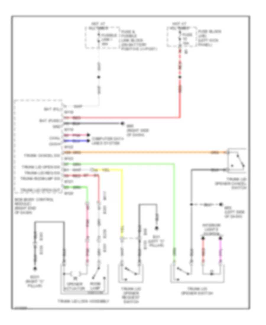 https://portal-diagnostov.com/license.html
Automotive Electricians Portal FZCO
Automotive Electricians Portal FZCO
https://portal-diagnostov.com/license.html
https://portal-diagnostov.com/license.html
Automotive Electricians Portal FZCO
Automotive Electricians Portal FZCOList of elements for Trunk Release Wiring Diagram for Nissan GT-R Premium 2014:
- B155
- B201
- B231 (right "c" pillar)
- B239
- B31 (left "c" pillar)
- B351
- B68
- Bat (f/l)
- Bat (fuse)
- Bcm (body control module) (right end of dash)
- Can-h
- Can-l
- Computer data lines system
- Fuse & fusible link block (on battery positive (+) post)
- Fuse 10a
- Fuse block (j/b) (left kick panel)
- Fusible link i 40a
- Gnd
- Hot at all times
- Interior lights system
- M117
- M118
- M119
- M120
- M121
- M122
- M123
- M55 (left side of dash)
- M95 (right side of dash)
- Opener actuator
- Pnk
- Red
- Room lamp switch
- Trunk cancel sw
- Trunk lid lock assembly
- Trunk lid open out
- Trunk lid open sw
- Trunk lid opener cancel switch
- Trunk lid opener request switch
- Trunk lid opener switch
- Trunk lid req sw
- Trunk room lmp sw
WARNING SYSTEMS
Chime Wiring Diagram for Nissan GT-R Premium 2014
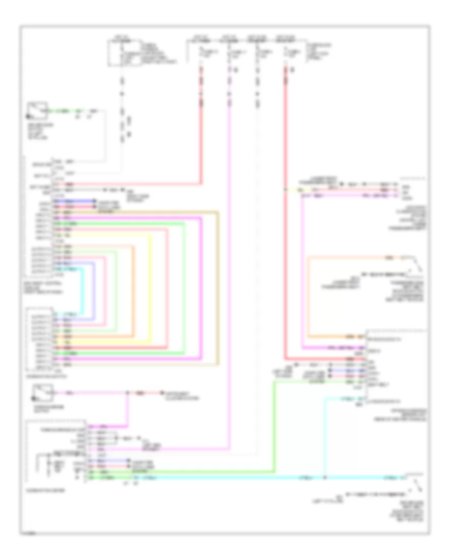 https://portal-diagnostov.com/license.html
Automotive Electricians Portal FZCO
Automotive Electricians Portal FZCO
https://portal-diagnostov.com/license.html
https://portal-diagnostov.com/license.html
Automotive Electricians Portal FZCO
Automotive Electricians Portal FZCOList of elements for Chime Wiring Diagram for Nissan GT-R Premium 2014:
- (under front passenger's seat) b214
- 11c
- 12c
- Air bag diagnosis sensor unit (rear of center console)
- B201 m117
- B214 (under front passenger's seat)
- B268
- B31 (left "c" pillar)
- B69
- Bat (f/l)
- Bat (fuse)
- Batt pwr sply
- Bcm (body control module) (right end of dash)
- Can-h
- Can-l
- Combination meter
- Combination switch
- Comm
- Computer data lines system
- Dr sw dr
- Driver door switch (in left "b" pillar)
- Driver side seat belt buckle switch (in driver's seat belt buckle)
- E106
- Fuse & fusible link block (on battery positive (+) post)
- Fuse 10 10a
- Fuse 11 10a
- Fuse 2 10a
- Fuse 4 10a
- Fuse block (j/b) (left kick panel)
- Fusible link i 40a
- Gnd
- Hot at all times
- Hot in on or start
- Ign
- Ill gnd
- Input 1
- Input 2
- Input 3
- Input 4
- Input 5
- Instrument cluster system
- Lh buckle sw in
- M11 (left end of dash)
- M118
- M119
- M122
- M123
- M157
- M33
- M55 (left side of dash)
- M95 (right side of dash)
- Occupant classification system control unit (under passenger's seat)
- Ods in
- Output 1
- Output 2
- Output 3
- Output 4
- Output 5
- Parking brake sw sig
- Parking brake switch
- Passenger side seat belt buckle switch (in passenger's seat belt buckle)
- Pnk
- Red
- Rh buckle sw in
- Seat belt
- Seat belt ind
Tire Pressure Monitoring Wiring Diagram for Nissan GT-R Premium 2014
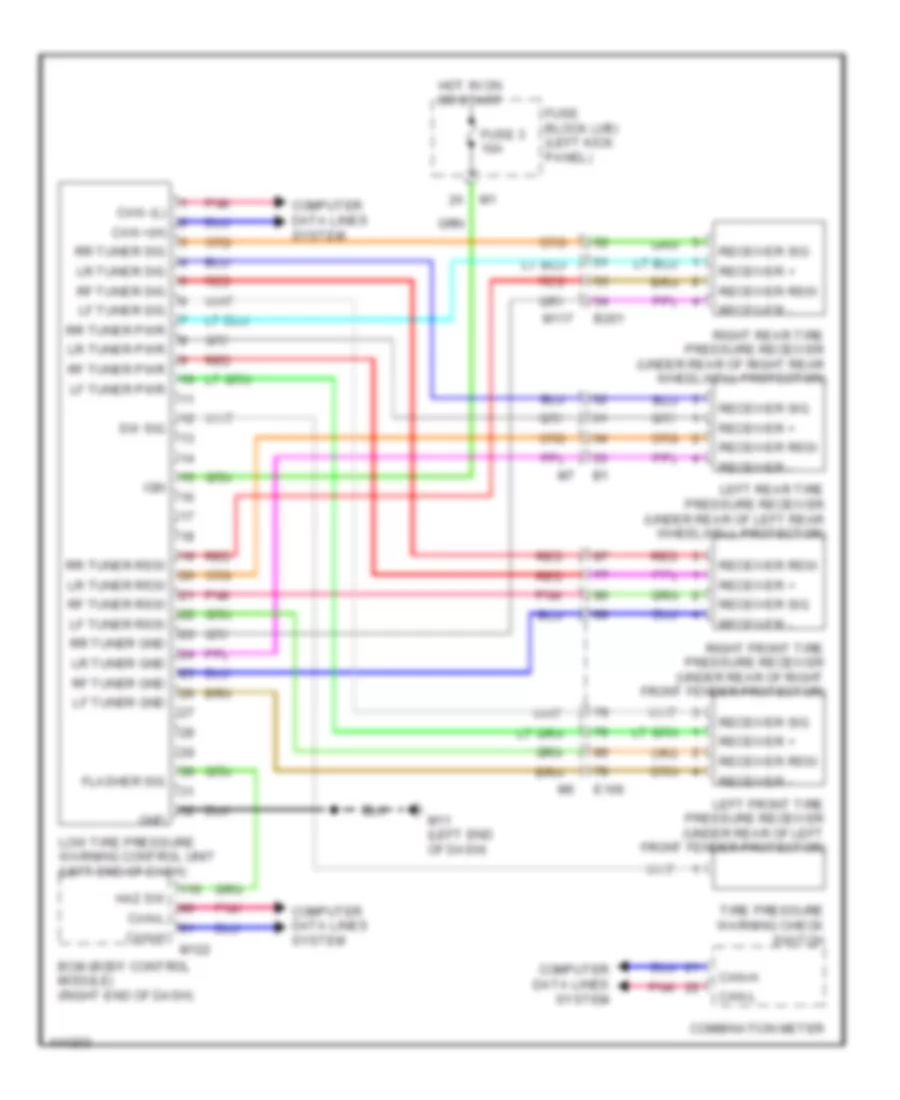 https://portal-diagnostov.com/license.html
Automotive Electricians Portal FZCO
Automotive Electricians Portal FZCO
https://portal-diagnostov.com/license.html
https://portal-diagnostov.com/license.html
Automotive Electricians Portal FZCO
Automotive Electricians Portal FZCOList of elements for Tire Pressure Monitoring Wiring Diagram for Nissan GT-R Premium 2014:
- B201
- Bcm (body control module) (right end of dash)
- Can +(h)
- Can -(l)
- Can-h
- Can-l
- Combination meter
- Computer data lines system
- E106
- Flasher sig
- Fuse 3 10a
- Fuse block (j/b) (left kick panel)
- Gnd
- Haz sw
- Hot in on or start
- Ign
- Left front tire pressure receiver (under rear of left front fender protector)
- Left rear tire pressure receiver (under rear of left rear wheelwell protector)
- Lf tuner gnd
- Lf tuner pwr
- Lf tuner rssi
- Lf tuner sig
- Low tire pressure warning control unit (left end of dash)
- Lr tuner gnd
- Lr tuner pwr
- Lr tuner rssi
- Lr tuner sig
- M11 (left end of dash)
- M117
- M122
- Pnk
- Receiver +
- Receiver -
- Receiver rssi
- Receiver sig
- Red
- Rf tuner gnd
- Rf tuner pwr
- Rf tuner rssi
- Rf tuner sig
- Right front tire pressure receiver (under rear of right front fender protector)
- Right rear tire pressure receiver (under rear of right rear wheelwell protector)
- Rr tuner gnd
- Rr tuner pwr
- Rr tuner rssi
- Rr tuner sig
- Sw sig
- Tire pressure warning check switch
WIPER/WASHER
Wiper/Washer Wiring Diagram for Nissan GT-R Premium 2014
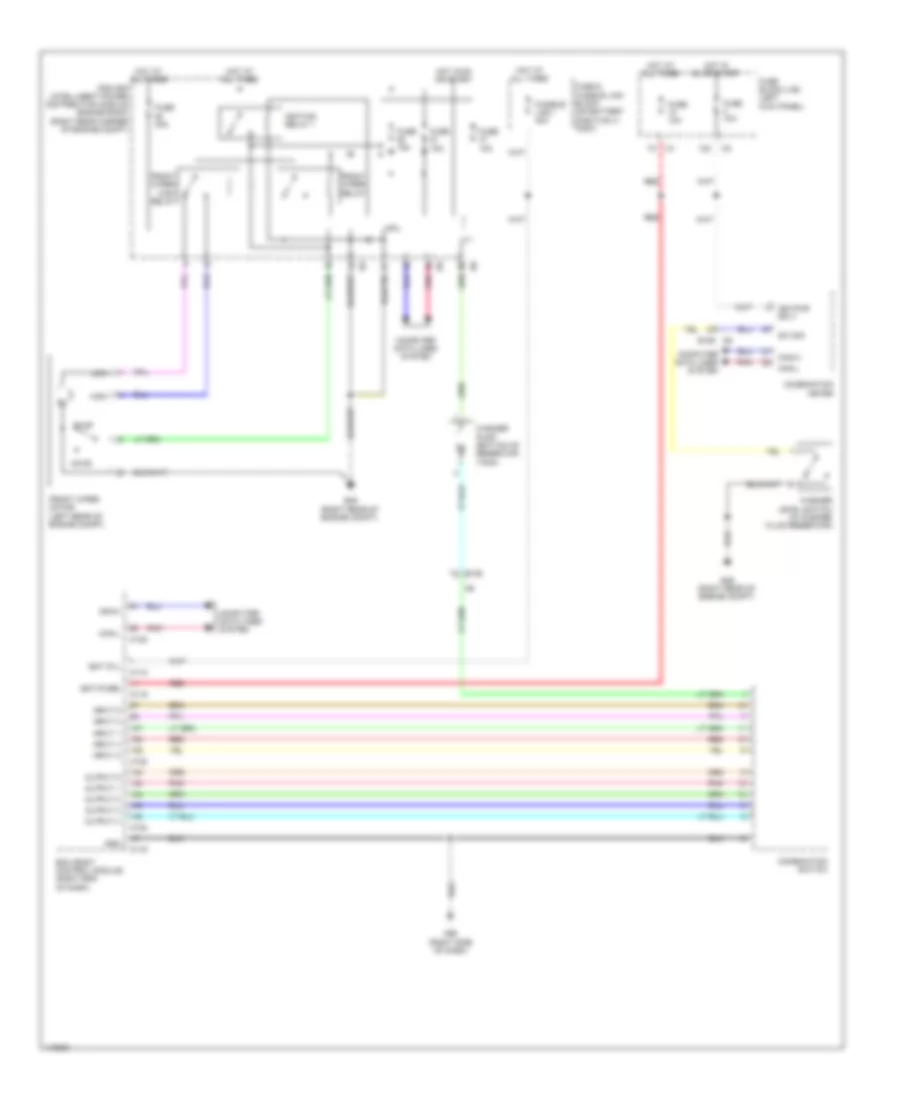 https://portal-diagnostov.com/license.html
Automotive Electricians Portal FZCO
Automotive Electricians Portal FZCO
https://portal-diagnostov.com/license.html
https://portal-diagnostov.com/license.html
Automotive Electricians Portal FZCO
Automotive Electricians Portal FZCOList of elements for Wiper/Washer Wiring Diagram for Nissan GT-R Premium 2014:
- 12c
- Bat (f/l)
- Bat (fuse)
- Bcm (body control module) (right end of dash)
- Can-h
- Can-l
- Combination meter
- Combination switch
- Computer data lines system
- Cpu
- E106
- E106 m6
- E46 (right rear of engine compt)
- Front wiper high relay
- Front wiper motor (left rear of engine compt)
- Front wiper relay
- Fuse & fusible link block (on battery positive (+) post)
- Fuse 10a
- Fuse 15a
- Fuse 30a
- Fuse block (j/b) (left kick panel)
- Fusible link i 40a
- Gnd
- High
- Hot at all times
- Hot in on or start
- Ign pwr sply
- Ignition relay 1
- Input 1
- Input 2
- Input 3
- Input 4
- Input 5
- Ipdm e/r (intelligent power distribution module engine room) (right rear corner of engine compt)
- Low
- M118
- M119
- M122
- M123
- M95 (right side of dash)
- Move
- Output 1
- Output 2
- Output 3
- Output 4
- Output 5
- Pnk
- Red
- Stop
- Sw sig
- Washer level switch (in washer fluid reservoir)
- Washer pump (bottom of reservoir tank)

 Čeština
 Dansk
Dansk Deutsch
 Ελληνικά
 English
 English
 Español
 Suomi
Suomi Français
 Français
 Hrvatski
 Magyar
 Italiano
 日本語
日本語 한국어
한국어 Nederlands
 Polski
 Português
 Português
 Română
 Русский
 Slovenčina
 Slovenščina
 Svenska
 Türkçe
 中文 (中国)
