
HORN
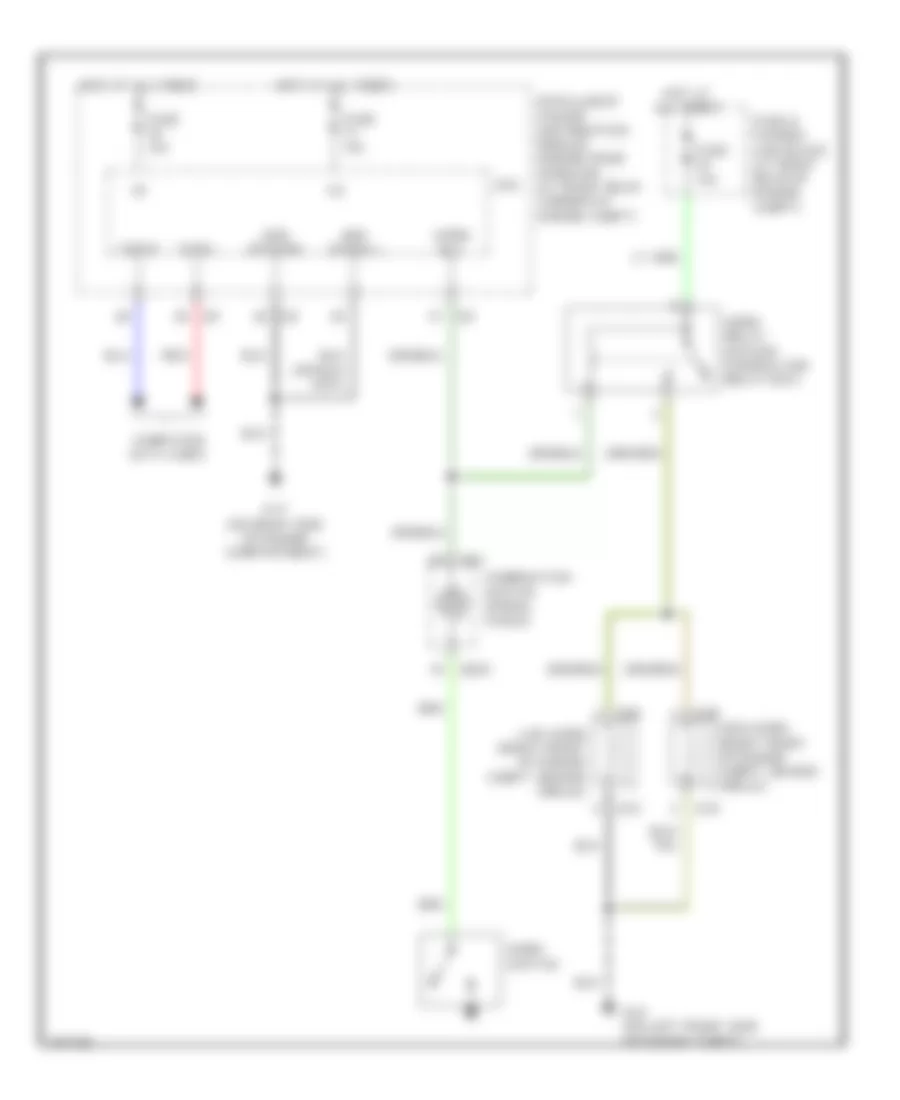
Horn Wiring Diagram for Infiniti G35 2004
List of elements for Horn Wiring Diagram for Infiniti G35 2004:
ANTI-LOCK BRAKESAIR CONDITIONINGANTI-THEFTCOMPUTER DATA LINESBODY CONTROL MODULESDEFOGGERSCRUISE CONTROLCOOLING FANEXTERIOR LIGHTSENGINE PERFORMANCEHORNINSTRUMENT CLUSTERHEADLIGHTSGROUND DISTRIBUTIONINTERIOR LIGHTSNAVIGATIONMEMORY SYSTEMSPOWER DISTRIBUTIONPOWER DOOR LOCKSPOWER SEATSRADIOPOWER MIRRORSPOWER TOP/SUNROOFTRANSMISSIONSTARTING/CHARGINGSHIFT INTERLOCKPOWER WINDOWSSUPPLEMENTAL RESTRAINTSTRUNK, TAILGATE, FUEL DOORWARNING SYSTEMSWIPER/WASHER