HORN
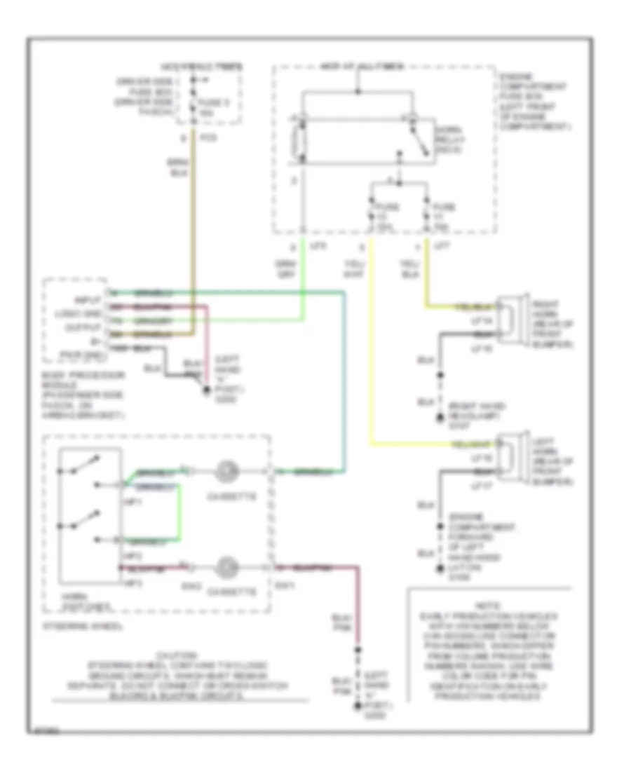
Horn Wiring Diagram for Jaguar XK8 1997
List of elements for Horn Wiring Diagram for Jaguar XK8 1997:
- (engine compartment, forward of left hand hood latch) g100
- (left hand "a" post) g202
- (right hand headlamp) g107
- Body processor module (passenger side fascia, on airbag bracket)
- Cassette
- Driver side fuse box (driver side fascia)
- Engine compartment fuse box (left front of engine compartment)
- Fc5
- Fuse 10a
- Fuse 5 15a
- Horn relay (no.6)
- Horn switches
- Hot at all times
- Hp1
- Hp2
- Hp3
- Input
- Left horn (rear of front bumper)
- Lf14
- Lf15
- Lf16
- Lf17
- Lf6
- Lf7
- Logic gnd
- Note: early production vehicles with vin numbers below (vin 003300) use connector pin numbers, which differ from volume production numbers shown. use wire color code for pin identification on early production vehicles.
- Output
- Pwr gnd
- Right horn (rear of front bumper)
- Steering wheel
- Sw1
- Sw2
 English