
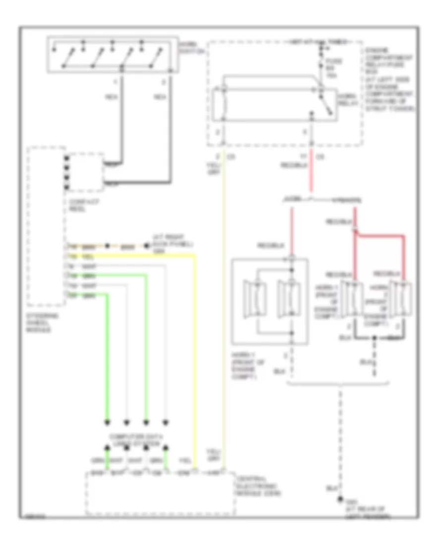
HORN
Horn Wiring Diagram for Volvo V70 T-5 2004
List of elements for Horn Wiring Diagram for Volvo V70 T-5 2004:
ANTI-THEFTANTI-LOCK BRAKESBODY CONTROL MODULESCOOLING FANCOMPUTER DATA LINESDEFOGGERSCRUISE CONTROLELECTRONIC POWER STEERINGENGINE PERFORMANCEEXTERIOR LIGHTSGROUND DISTRIBUTIONINSTRUMENT CLUSTERELECTRONIC SUSPENSIONHORNHEADLIGHTSINTERIOR LIGHTSNAVIGATIONPOWER DISTRIBUTIONMEMORY SYSTEMSPOWER MIRRORSPOWER DOOR LOCKSSTARTING/CHARGINGSHIFT INTERLOCKPOWER WINDOWSRADIOPOWER SEATSSUPPLEMENTAL RESTRAINTSPOWER TOP/SUNROOFWARNING SYSTEMSTRANSMISSIONWIPER/WASHERAIR CONDITIONING