ELECTRONIC SUSPENSION
Electronic Suspension Wiring Diagram for Jaguar XJR 2003
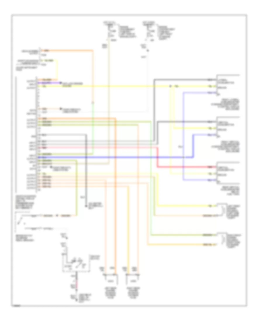
List of elements for Electronic Suspension Wiring Diagram for Jaguar XJR 2003:
- (center of dash, on firewall) fc17
- (i) acc
- (ii) run
- (on center of firewall) em17
- Adaptive damping control module (next to passenger side blower/ glove box assembly)
- Adaptive damping warning input
- Anti-lock brakes system
- Brake switch (on brake pedal bracket)
- Computer data lines system
- Data
- Em20
- Engine compartment fuse box (left front of engine compt)
- Engine management fuse box (left side of engine compt)
- Fc24
- Fc25
- Front lateral accelerometer (in engine compartment, in control module enclosure)
- Front vertical accelerometer (in engine compartment, in control module enclosure)
- Fuse 10a
- Fuse 20a
- Gnd
- Ground
- Hot at all times
- Hot in run & start
- Ignition
- Ignition switch
- Input
- Lateral acceleration
- Left front damper solenoid (left side of engine compt)
- Left rear damper solenoid (on rear axle)
- Ls6
- Major instrument pack
- Nca
- Off (0)
- Output
- Rear vertical accelerometer (below fuel tank)
- Red
- Right front damper solenoid (right side of engine compt)
- Right rear damper solenoid (on rear axle)
- Start (iii)
- Vehicle speed output
- Vertical acceleration
 Čeština
 Dansk
Dansk Deutsch
 Ελληνικά
 English
 English
 Español
 Suomi
Suomi Français
 Français
 עברית
עברית Magyar
 Italiano
 日本語
日本語 한국어
한국어 Nederlands
 Polski
 Português
 Português
 Română
 Русский
 Slovenčina
 Slovenščina
 Svenska
 Türkçe
 中文 (中国)
 Hrvatski