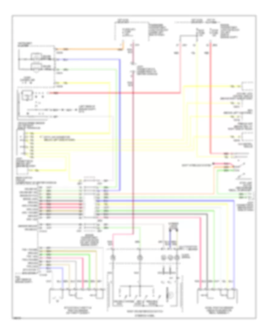
CRUISE CONTROL
Cruise Control Wiring Diagram for Hyundai Azera Limited 2007
List of elements for Cruise Control Wiring Diagram for Hyundai Azera Limited 2007:
- (left rear of engine compt) g115
- A/c control module
- Accel position sensor (above accelerator pedal assembly)
- Aps 1 power
- Aps 1 sig
- Aps 2 power
- Aps 2 sig
- Atm key lock control module (behind right side of dash)
- B/up fuse 10a
- Bcm (behind left kick panel)
- Brake lamp
- Brake switch
- C144-a
- C144-b
- Cancel
- Clock spring
- Cruise ind
- Cruise main
- Cruise set ind
- Cruise sw
- Data link connector (below left side of dash)
- Engine compartment junction block (on left side of engine compt)
- Etc motor & throttle position sensor (on throttle body)
- Etc motor +
- Etc motor -
- F57-b
- Ground
- Hall ic
- Hot at all times
- Hot in on or start
- I/p-f
- Illumination
- Instrument cluster
- Interior lights system
- Jc01
- Jco1
- Je01
- Je02
- Joint connector e1 (behind right side of dash)
- Joint connector m10 (under front of center console)
- Joint connector m2 (behind left center of dash)
- M14
- M28-c
- M32-a
- M32-b
- M50-b
- Micro controller
- Module 2 fuse 10a
- Multi-function switch
- Nca
- Passenger compartment junction block (under left end of dash)
- Pcm (left rear of engine compt)
- Pnk
- Premium amp (behind trim, at right side of trunk)
- Rear curtain module (under front of center console)
- Red
- Resume/ accel
- Right cruise remocon switch
- Sensor ground
- Set/ coast
- Shift interlock system
- Steering wheel
- Stop fuse 15a
- Stop lamp switch (above brake pedal, on bracket)
- Tps 1 power
- Tps 1 sig
- Tps 2 power
- Tps 2 sig
- Vehicle speed sensor (on top right side of transaxle)
 Čeština
 Dansk
Dansk Deutsch
 Ελληνικά
 English
 English
 Español
 Suomi
Suomi Français
 Français
 עברית
עברית Magyar
 Italiano
 日本語
日本語 한국어
한국어 Nederlands
 Polski
 Português
 Português
 Română
 Русский
 Slovenčina
 Slovenščina
 Svenska
 Türkçe
 中文 (中国)
 Hrvatski