POWER DISTRIBUTION
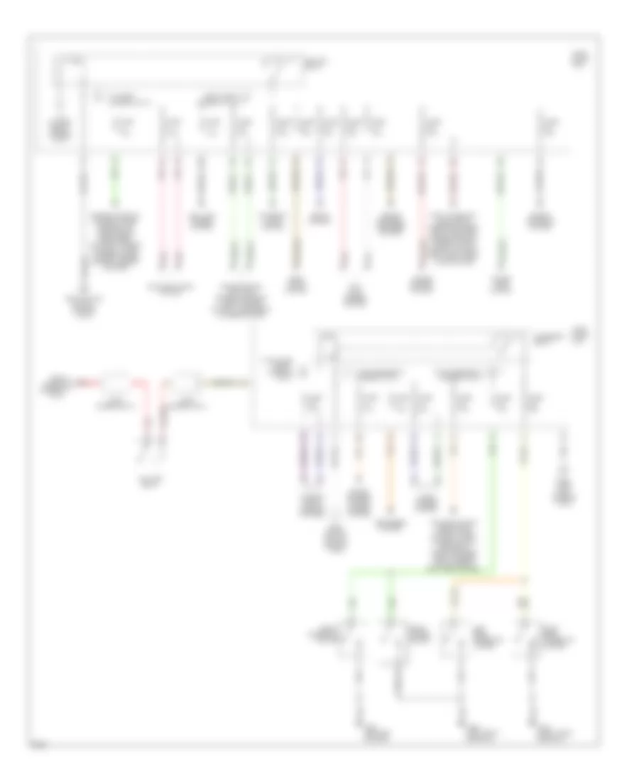
Power Distribution Wiring Diagram (1 of 3) for Infiniti Q45 1997


List of elements for Power Distribution Wiring Diagram (1 of 3) for Infiniti Q45 1997:
- 11b
- 12b
- 13b
- 16b
- Acc
- Air conditioning system
- Alternator
- Anti-lock brakes system
- Anti-lock brakes, horns, air conditioning, anti-theft system
- Battery
- Circuit breaker 1
- Circuit breaker 2
- Engine controls, anti- theft system
- Engine controls, defoggers system
- Exterior lights, door locks system
- From b fuse 64 (diagram 1 of 3)
- Fuse 10a
- Fuse 15a
- Fuse 20a
- Fuse 7.5a
- Fuse block (j/b)
- Fuse link b 80a
- Fuse link c 80a
- Fuse link f 30a
- Fuse link g 30a
- Fuse link h 40a
- Fuse link i 30a
- Fuse link j 30a
- Fuse link k 30a
- Fuse, fusible link and relay box
- Fusible link a 120a
- Fusible link box
- G202 (left end of dash)
- Head- lights system
- Headlights system
- Headlights, warning systems, horns, defoggers, power windows, body computer, door locks, anti-theft system, interior lights system
- Horns, cruise control, anti-theft system
- Ignition switch
- Integrated homelink transmitter
- Interior lights system
- Lock
- Pnk
- Power tops, body computer, power windows, door locks, interior lights system, anti- theft system
- Red
- Red a
- Run
- Seats, body computer, power windows, memory systems
- Shift interlock, transmissions, exterior lights, cruise control system
- Shift interlock, trunk, tailgate, fuel doors, door locks system
- Shift interlock, warning systems, door locks, interior lights, memory systems
- Sound systems
- Start
- Starter
- Starting/ charging system
- To accy relay (diagram 2 of 3)
- To blower relay (diagram 3 of 3)
- To fuse 53 (diagram 1 of 3)
- To ignition relay (diagram 2 of 3)
- To joint connector 15 (diagram 2 of 3)
- Transmissions, power antenna system
- Warning systems, cellular phones system
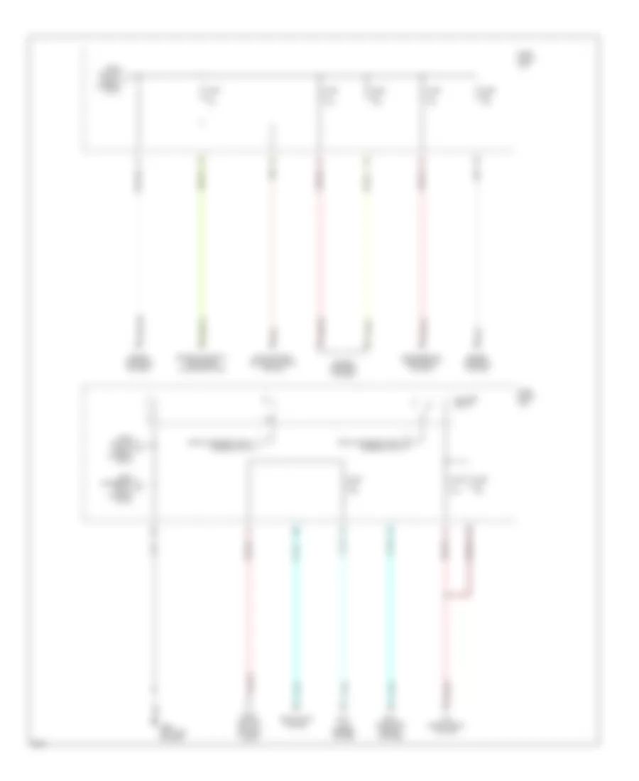
Power Distribution Wiring Diagram (2 of 3) for Infiniti Q45 1997
List of elements for Power Distribution Wiring Diagram (2 of 3) for Infiniti Q45 1997:
- 10a
- 10c
- 13h
- 15b
- 17b
- 18b
- 19b
- Accessory relay
- Air conditioning headlights system, wiper/ washer system, horn, body computer, door locks, interior lights, memory, anti-theft system
- Air conditioning system
- Anti- lock brakes system
- Cellular phones system
- Cruise control system
- Defoggers system
- Engine controls system
- Engine controls system, trans- missions, air conditioning, instrument cluster, warning systems, wiper/ washer, cruise control, memory systems
- Engine controls, defogger system
- Exterior lights system
- From fuse 40 g (diagram 1 of 3)
- From fuse 63 a (diagram 1 of 3)
- From fuse link c (diagram 1 of 3)
- From ignition switch (diagram 1 of 3)
- Front cigarette lighter
- Front power socket
- Fuse 10a
- Fuse 15a
- Fuse 20a
- Fuse 7.5a
- Fuse block (j/b)
- G202 (left end of dash)
- G309 (left front door sill)
- G316 (right front door sill)
- Head- lights system
- Ignition relay
- Interior lights, warning systems
- Joint connector 13
- Joint connector 15
- Left rear cigarette lighter
- Pnk
- Power tops system
- Red
- Right rear cigarette lighter
- Seats system
- Shift interlock, headlights, warning systems, body computer, power windows, interior lights, memory systems, anti-theft, door locks system
- Sound systems, power antenna system
- Taillamp relay
- To blower relay (diagram 3 of 3)
- To fuse 2 (diagram 3 of 3)
- Transmissions, anti-lock brakes, exterior lights, cruise control, instrument cluster system
- Wiper/ washer system
Power Distribution Wiring Diagram (3 of 3) for Infiniti Q45 1997
List of elements for Power Distribution Wiring Diagram (3 of 3) for Infiniti Q45 1997:
- 10d
- 12g
- 14b
- Air conditioning system
- Anti- lock brakes system
- Blower relay
- Body computer, memory systems
- Cooling fans, air conditioning system
- Engine controls system
- Engine controls, instrument cluster system
- From accessory relay (diagram 2 of 3)
- From accessory relay l (diagram 2 of 3)
- From accessory relay m (diagram 2 of 3)
- From ignition relay (diagram 2 of 3)
- From ignition switch (diagram 1 of 3)
- Fuse 10a
- Fuse 15a
- Fuse 7.5a
- Fuse block (j/b)
- G202 (left end of dash)
- Headlights system

 Čeština
 Dansk
Dansk Deutsch
 Ελληνικά
 English
 English
 Español
 Suomi
Suomi Français
 Français
 עברית
עברית Magyar
 Italiano
 日本語
日本語 한국어
한국어 Nederlands
 Polski
 Português
 Português
 Română
 Русский
 Slovenčina
 Slovenščina
 Svenska
 Türkçe
 中文 (中国)