INSTRUMENT CLUSTER
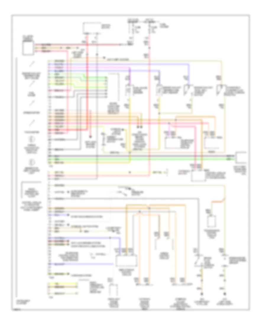
Instrument Cluster Wiring Diagram for Audi A4 2002
List of elements for Instrument Cluster Wiring Diagram for Audi A4 2002:
- (left side of eng compt)
- (lower right "a" pillar)
- 12a
- 86s
- Air conditioning, memory, power windows, door locks, systems
- Airbag control module
- Airbag malfunction indicator lamp (mil)
- Ambient temperature switch
- Anti-lock brakes system
- Anti-theft immobilzer induction coil
- Anti-theft system
- Board computer function selector switch ii
- Brake fluid level warning switch
- Computer data-lines system
- Control module for navigation w/ cd-mechanism
- Control module w/ indicator unit in instrument panel insert
- Engine coolant level (ecl) warning switch
- Engine coolant temperature (ect) gauge
- Engine coolant temperature (ect) sensor
- Fuel gauge
- Fuel gauge gauge sender
- Fuse 10a
- Fuse holder
- G12
- G12 (left side of eng compt)
- G43
- G43 (lower right "a" pillar)
- Generator (gen) warning light
- Headlight range control module
- Hot at all times
- Hot in on or start
- Ignition switch
- Instrument cluster
- Interior lights system
- Motronic engine control module (ecm)
- Oil level thermal sensor
- Oil pressure switch
- Radio
- Radio frequency controlled clock
- Radio frequency controlled clock receiver
- Red
- Servotronic control module
- Speedometer
- Speedometer vehicle speed sensor
- Starting/charging system
- Steering column electronic systems control module
- T16a
- T18
- T20d
- T20e
- T32
- T32a
- T42
- T4m
- Tachometer
- Telephone control module for operating electronics
- Telephone/ telematic control module
- Tiptronic switch
- Transmission control module (tcm)
- Warnings system
- Windshield washer fluid level warning switch
 Čeština
 Dansk
Dansk Deutsch
 Ελληνικά
 English
 English
 Español
 Suomi
Suomi Français
 Français
 עברית
עברית Magyar
 Italiano
 日本語
日本語 한국어
한국어 Nederlands
 Polski
 Português
 Português
 Română
 Русский
 Slovenčina
 Slovenščina
 Svenska
 Türkçe
 中文 (中国)
 Hrvatski