AIR CONDITIONING
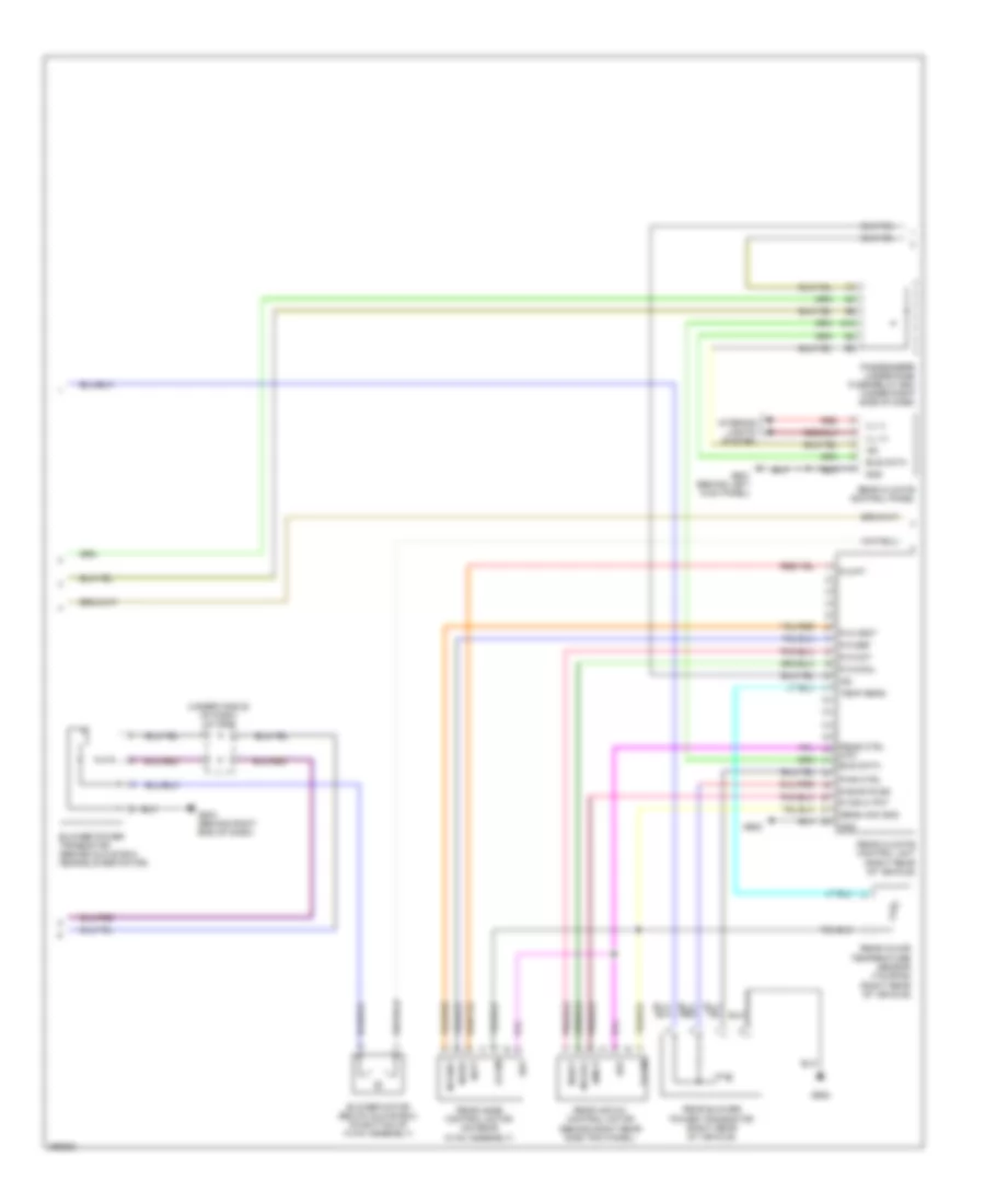
Automatic A/C Wiring Diagram, EX, EX-L, Touring (1 of 3) for Honda Odyssey EX 2007
 https://portal-diagnostov.com/license.html
Automotive Electricians Portal FZCO
Automotive Electricians Portal FZCO
https://portal-diagnostov.com/license.html
https://portal-diagnostov.com/license.html
Automotive Electricians Portal FZCO
Automotive Electricians Portal FZCO
List of elements for Automatic A/C Wiring Diagram, EX, EX-L, Touring (1 of 3) for Honda Odyssey EX 2007:
- (behind left side of front bumper) outside air temperature sensor
- (behind right rear side trim panel)
- (left kick panel)
- (not used)
- (on left side of dash) in-car temperature sensor
- (on rear hvac assembly) rear blower motor
- (top of dash) automatic lighting sensor/sunlight sensor
- A/c pre sw
- A/c pressure switch (at right side of engine compt, on a/c receiver line)
- A/c sig
- A13
- A14
- A15
- Ac-ck
- Ac-si
- Ac-so
- Air temp sens
- Amd-p
- Amd-p as
- Amd-p dr
- Bus data
- Bwr feedback
- Climate control panel
- Climate control unit (behind glove box)
- Control block
- D11
- Driver's air mix control motor (under left side of dash)
- Driver's under-dash fuse/relay box (under left side of dash)
- E11
- E12
- Evap temp sens
- Evaporator temperature sensor (under left side of dash)
- Ex & ex-l
- Fresh
- Front passenger's air mix control motor (under right side of dash)
- Frs
- Fuse 30a
- G401
- G504 (behind right end of dash)
- G652
- Gnd
- Hot at all times
- Ig2
- Ill (+)
- Ill (-)
- Interior lights system
- J/c c506 (under middle of dash)
- J/c c507 (behind right end of dash)
- J12
- M-cool
- M-cool as
- M-cool dr
- M-def
- M-hot
- M-hot as
- M-hot dr
- M-vent
- Micu-rear junction box
- Micu-rear junction box control unit
- Mode 1
- Mode 2
- Mode 3
- Mode 4
- Mode control motor (behind glove box)
- N22
- Navigation unit (if equipped, ex-l & touring)
- Passenger's under-dash fuse/relay box (under right side of dash)
- Pnk
- Pwr trns ctrl
- Rear blower motor relay
- Rec
- Recirculate
- Recirculation control motor (behind glove box, on hvac assembly)
- Red
- Relay control module
- S-com
- S5v
- Sunlight sens
- Sunlight sensor
- Sunlight sensor (top of dash)
- Temp sens
- Touring
- Under-hood fuse/relay box (right side of engine compt)
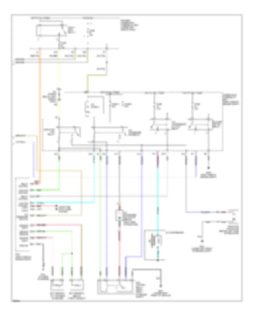
Automatic A/C Wiring Diagram, EX, EX-L, Touring (2 of 3) for Honda Odyssey EX 2007
List of elements for Automatic A/C Wiring Diagram, EX, EX-L, Touring (2 of 3) for Honda Odyssey EX 2007:
- (right rear of vehicle)
- (under middle of dash) j/c c506
- Amd-p
- Blower motor (below glove box, on bottom of hvac assembly)
- Blower power transistor (behind glove box, near blower motor)
- Bus data
- G12
- G504 (behind right end of dash)
- G601 (behind left kick panel)
- G652
- Gnd
- Ig2
- Ill (+)
- Ill (-)
- Interior lights system
- M-cool
- M-def
- M-hot
- M-pt
- M-vent
- Passenger's under-dash fuse/relay box (under right side of dash)
- Pwr ctrl
- R air m- pot
- R bwr fd bk
- R m-cool
- R m-def
- R m-hot
- R m-pt
- R m-vent
- Rear air mix control motor (behind right rear side trim panel)
- Rear blower power transistor (right rear of vehicle)
- Rear climate control panel
- Rear climate control unit (right rear of vehicle)
- Rear ctrl m-pt
- Rear in-car temperature sensor (touring)
- Rear mode control motor (on rear hvac assembly)
- Red
- S-com
- S5v
- Sens com gnd
- Temp sens
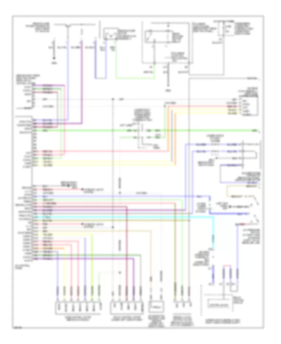
Automatic A/C Wiring Diagram, EX, EX-L, Touring (3 of 3) for Honda Odyssey EX 2007
List of elements for Automatic A/C Wiring Diagram, EX, EX-L, Touring (3 of 3) for Honda Odyssey EX 2007:
- A/c
- A/c compressor
- A/c compressor clutch relay
- A/c condenser fan motor (behind right side of radiator)
- A/c condenser fan relay
- A/c diode a
- A/c pressure switch
- A13
- A47
- A48
- A49
- Blower motor relay
- C16
- C31
- C32
- Can-h
- Compressor clutch
- Computer data lines system
- D16
- Driver's under-dash fuse/relay box (under left side of dash)
- E10
- E14
- E15
- Ect sensor 1 (at top rear of engine)
- Ect sensor 2 (below throttle body)
- F10
- F14
- F15
- F17
- F19
- Fan control relay (right front of engine compt)
- Fuse 10a
- Fuse 11 30a
- Fuse 40a
- Fuse 7.5a
- Fuse 9 30a
- G101 (at rear of engine)
- G201 (lower right front of vehicle)
- G202 (right side of engine compt)
- G301 (under left front of engine compt)
- Ground
- High fan control
- Hot at all times
- Hot in on
- Low fan control can-l
- N20
- Pcm (right side of engine compt)
- Pgm-f1 main relay 1
- Radiator fan motor (behind left side of radiator)
- Radiator fan relay
- Red
- Relay control
- Sensor ground
- Sensor input
- Under-hood fuse/relay box (right side of engine compt)
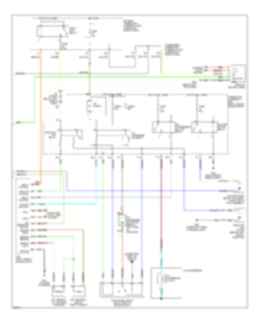
Manual A/C Wiring Diagram, LX (1 of 2) for Honda Odyssey EX 2007
List of elements for Manual A/C Wiring Diagram, LX (1 of 2) for Honda Odyssey EX 2007:
- (behind right end of dash) g504
- (behind right rear side trim panel) rear air mix control motor
- (left kick panel) g401
- (not used)
- (on rear hvac assembly) rear mode control motor
- (under middle of dash) j/c c506
- (under right side of dash) passenger's under-dash fuse/relay box
- A/c control panel
- A/c pre sw
- A/c pressure switch (at right side of engine compt, on a/c receiver line)
- A/c signal
- A10
- A11
- A12
- A13
- A14
- A15
- A16
- A17
- A18
- A19
- A20
- A21
- A22
- Air mix control motor (under left side of dash)
- Amd-p
- B10
- B11
- B12
- B13
- B14
- Blower power transistor (behind glove box, near blower motor)
- Bus data
- Bwr fd bk
- Control block
- D11
- Driver's under-dash fuse/relay box (under left side of dash)
- E11
- Evap sens
- Evaporator temperature sensor (under left side of dash)
- Fresh
- Frs
- Fuse 30a
- G12
- G504 (behind right end of dash)
- G652
- Ground
- Hot at all times
- Ig2
- Ill (+)
- Ill (-)
- Interior lights system
- J/c c506 (under middle of dash)
- J12
- M-cool
- M-def
- M-hot
- M-pt
- M-vent
- Micu-rear junction box (behind right rear side trim panel)
- Micu-rear junction box control unit
- Mode 1
- Mode 2
- Mode 3
- Mode 4
- Mode control motor (behind glove box)
- N22
- Passenger's under-dash fuse/relay box (under right side of dash)
- Pwr ctrl
- R bwr fdbk
- Rear blower motor (on rear hvac assembly)
- Rear blower motor relay
- Rear blower power transistor (right rear of vehicle)
- Rec
- Recirculate
- Recirculation control motor (behind glove box, on hvac assembly)
- Red
- Relay control module
- S-com
- S5v
- Trns ctrl
- Under-hood fuse/relay box (right side of engine compt)
Manual A/C Wiring Diagram, LX (2 of 2) for Honda Odyssey EX 2007
List of elements for Manual A/C Wiring Diagram, LX (2 of 2) for Honda Odyssey EX 2007:
- (lower right front of vehicle) g201
- A/c compressor
- A/c compressor clutch
- A/c compressor clutch relay
- A/c condenser fan motor (behind right side of radiator)
- A/c condenser fan relay
- A/c diode a
- A/c pressure switch
- A13
- A47
- A48
- A49
- Blower motor (below glove box, on bottom of hvac assembly)
- Blower motor relay
- Bus data
- C16
- C31
- C32
- Can-h
- Can-l
- Computer data lines system
- D16
- Driver's under-dash fuse/relay box (under left side of dash)
- E10
- E14
- E15
- Ect sensor 1 (at top rear of engine)
- Ect sensor 2 (below throttle body)
- F10
- F14
- F15
- F17
- F19
- Fan control relay (right front of engine compt)
- Fuse 10a
- Fuse 11 30a
- Fuse 40a
- Fuse 7.5a
- Fuse 9 30a
- G101 (at rear of engine)
- G202 (right side of engine compt)
- G301 (under left front of engine compt)
- G601 (behind left kick panel)
- Gnd
- Ground
- High fan control
- Hot at all times
- Hot in on
- Ig2
- Ill (+)
- Ill (-)
- Interior lights system
- Low fan control
- N20
- Passenger's under-dash fuse/relay box (under right side of dash)
- Pcm (right side of engine compt)
- Pgm-f1 main relay 1
- Radiator fan motor (behind left side of radiator)
- Radiator fan relay
- Rear a/c control panel
- Red
- Relay control
- Sensor ground
- Sensor input
- Under-hood fuse/relay box (right side of engine compt)

 Čeština
 Dansk
Dansk Deutsch
 Ελληνικά
 English
 English
 Español
 Suomi
Suomi Français
 Français
 עברית
עברית Magyar
 Italiano
 日本語
日本語 한국어
한국어 Nederlands
 Polski
 Português
 Português
 Română
 Русский
 Slovenčina
 Slovenščina
 Svenska
 Türkçe
 中文 (中国)